

Page 1
Guardian™
SERIAL RADIO MODEM
User Manual
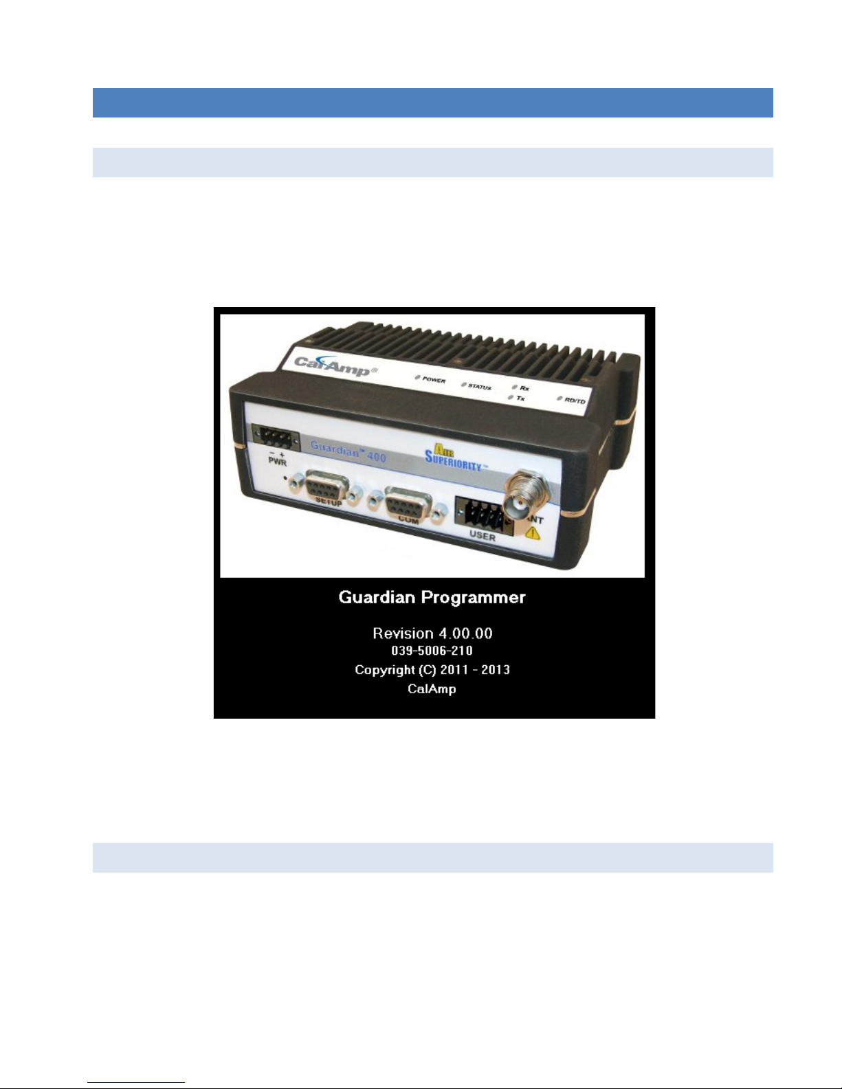
Guardian
PN 001-5006-000 Rev. 3
Revised April 2013
™ Serial Radio Modem
Page 2

REVISION HISTORY
REV
DATE
REVISION DETAILS
0 July 2011 Initial release as 001-5006-000.
1 August 2011
2 October 2012 Added UL Information.
3 April 2013
Added User Configuration section 5.1.3 Modem Mode.
Added Link Configuration section 5.1.4 Modem Mode.
Added User Configuration section 5.1.5 Loader Mode.
Added Link Configuration section 5.1.6 Loader Mode.
Updated to be current with version 4.0 Field Programming Software and version 1.3
firmware. Added Section 2.5 for lightning arrestor information and added appendices for
DL-3400 interoperability, DL-3282 modem interface, and T-96SR interoperability.
Page 3
Important Notice
Minimum Safety Distance
Antenna Gain
UHF at Maximum Power
105.7 cm
188 cm
334.4 cm
Because of the nature of wireless communication, transmission and reception of data can never be
guaranteed. Data may be delayed, corrupted (i.e. have errors), or be totally lost. Significant delays or losses
of data are rare when wireless devices such as CalAmp provides are used in a normal manner with a wellconstructed network. These products should not be used in situations where failure to transmit or receive
data could result in damage of any kind to the user or any other party, including but not limited to personal
injury or death, or loss of property. CalAmp accepts no responsibility for damages of any kind resulting from
delays or errors in data transmitted or received using the Guardian serial radio, or for failure to transmit or
receive such data.
Copyright Notice
© Copyright 2011-2013 CalAmp. All rights reserved.
Products offered may contain software proprietary to CalAmp or other parties. The offer of supply of these
products and services does not include or infer any transfer of ownership. No part of the documentation or
information supplied may be divulged to any third party without the express written consent of CalAmp.
CalAmp reserves the right to update its products, software, or documentation without obligation to notify
any individual or entity. Product updates may result in differences between the information provided in this
manual and the product shipped. For access to the most current product documentation and application
notes, visit
www.calamp.com
.
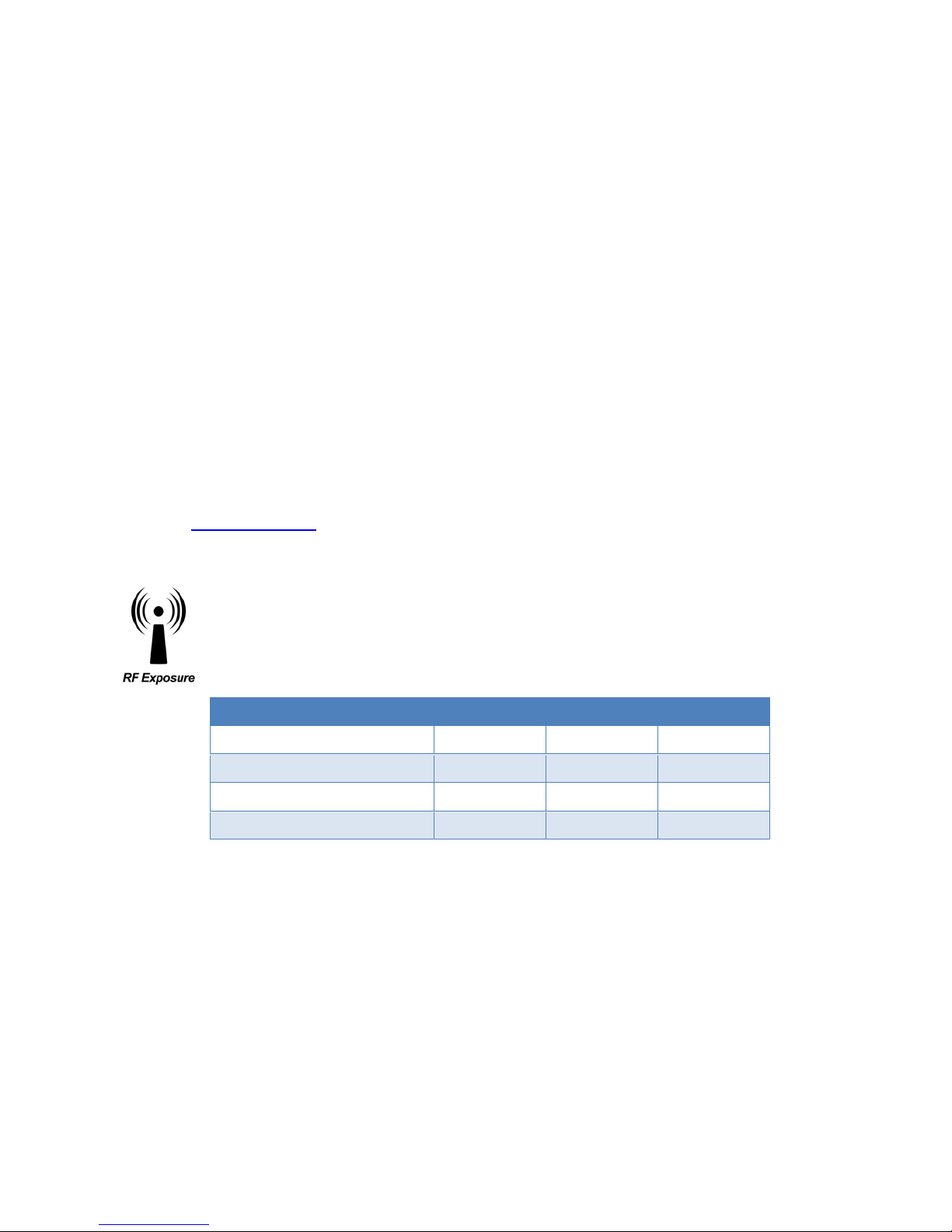
RF Exposure Compliance Requirements
The Guardian serial radio is intended for use in the Industrial Monitoring and Control and
SCADA markets. The Guardian unit must be professionally installed and must ensure a
minimum separation distance listed in the table below between the antenna or radiating
structure and any person. An antenna mounted on a pole or tower is the typical installation
and in rare instances, a ½-wave whip antenna is used.
5 dBi 10 dBi 15 dBi
VHF at maximum Power 123 cm 218.8 cm 389 cm
900 MHz at Maximum Power 63.8 cm 115 cm 201.7 cm
Note: It is the responsibility of the user to guarantee compliance with the FCC MPE regulations when
operating this device in a way other than described above.
The Guardian serial radio uses a low power radio frequency transmitter. The concentrated energy from an
antenna may pose a health hazard. People should not be in front of the antenna when the transmitter is
operating.
The installer of this equipment must ensure the antenna is located or pointed such that it does not emit an
RF field in excess of Health Canada limits for the general population. Recommended safety guidelines for the
human exposure to radio frequency electromagnetic energy are contained in the Canadian Safety Code 6
(available from Health Canada), the Federal Communications Commission (FCC) Bulletin 65.
Any changes or modifications not expressly approved by the party responsible for compliance (in the
country where used) could void the user’s authority to operate the equipment.
Guardian™ Serial Modem or Analog Radio for Licensed Spectrum PN 001-5006-000 Rev. 3 | Page i
Page 4

Regulation Certifications
FCC
140-5046-501
450 - 512 MHz
NP4-5046-300
773B-5046300
140-5096-500
928 - 960 MHz
NP4-5096-500
773B-5096500
140-5096-501
928 - 960 MHz
NP4-5096-500
773B-5096500
The Guardian serial radio is available in several different models, each with unique frequency bands. Each
model of Guardian may have different regulatory approval, as shown in the table below.
Certifications
Model Number Frequency Range
140-5016-500 136 – 174 MHz NP4-5016-500 773B-5016500
140-5016-501 136 – 174 MHz NP4-5016-500 773B-5016500
140-5026-500 216 – 222 MHz NP4-5026-500 773B-5026500
140-5026-501 216 – 222 MHz NP4-5026-500 773B-5026500
140-5046-300 406 - 470 MHz NP4-5046-300 773B-5046300
140-5046-301 406 - 470 MHz NP4-5046-300 773B-5046300
140-5046-500 450 - 512 MHz NP4-5046-300 773B-5046300
All models UL approved when powered with a listed Class 2 source.
UL Certification
This device is suitable for use in Class I, Division 2, Groups A, B, C and D or nonhazardous locations only.
IC (DOC)
Guardian™ Serial Modem or Analog Radio for Licensed Spectrum PN 001-5006-000 Rev. 3 | Page ii
Page 5

TABLE OF CONTENTS
1 Guardian Overview ......................................................................................................................... 1
1.1 General Description ............................................................................................................................................... 1
1.2 Operational Characteristics .................................................................................................................................... 1
1.3 Link Configurations ................................................................................................................................................ 2
1.4 Physical Description ............................................................................................................................................... 3
1.4.1 Front Panel .................................................................................................................................................... 3
1.4.2 LED Panel ...................................................................................................................................................... 3
1.4.3 User Interface Port ....................................................................................................................................... 4
1.4.4 Setup and COM Ports.................................................................................................................................... 5
1.4.5 Power Connector .......................................................................................................................................... 6
1.4.6 Antenna Connector ....................................................................................................................................... 6
1.4.7 Chassis Dimensions ....................................................................................................................................... 7
1.5 Part Numbers and Availability ............................................................................................................................... 7
1.5.1 Guardian Radio ............................................................................................................................................. 7
1.5.2 Accessories and Options ............................................................................................................................... 8
2 System Architecture and Network Planning ................................................................................... 9
2.1 Single Coverage Area ............................................................................................................................................. 9
2.2 Network Architecture ............................................................................................................................................ 9
2.2.1 Point-To-Point ............................................................................................................................................... 9
2.2.2 Point-To-Multipoint .................................................................................................................................... 10
2.2.3 Multiple Point-To-Point .............................................................................................................................. 10
2.2.4 Peer-To-Peer ............................................................................................................................................... 10
2.2.5 Store And Forward ...................................................................................................................................... 10
2.2.6 Network Using a Guardian for Online Diagnostics ..................................................................................... 11
2.3 Understanding RF Path Requirements ................................................................................................................. 11
2.4 Site Selection and Site Survey .............................................................................................................................. 11
2.4.1 Site Selection .............................................................................................................................................. 11
2.4.2 Site Survey .................................................................................................................................................. 12
2.5 Selecting Antenna and Lightning Arrestor Combinations .................................................................................... 12
2.5.1 Lightning Arrestor Overview ....................................................................................................................... 12
2.5.2 Antenna Overview ...................................................................................................................................... 12
2.5.3 The Wrong Combination ............................................................................................................................. 12
2.5.4 Good Design Practices ................................................................................................................................ 14
2.6 Selecting Antenna and Feedline ........................................................................................................................... 14
2.6.1 Antenna Gain .............................................................................................................................................. 14
2.6.2 Omni-Directional Antenna .......................................................................................................................... 15
2.6.3 Yagi Antenna ............................................................................................................................................... 15
2.6.4 Vertical Dipoles ........................................................................................................................................... 15
2.6.5 Feedline ...................................................................................................................................................... 15
2.6.6 RF Exposure Compliance Requirements ..................................................................................................... 16
Guardian™ Serial Modem or Analog Radio for Licensed Spectrum PN 001-5006-000 Rev. 3 | Page iii
Page 6

2.7 Terrain and Signal Strength .................................................................................................................................. 17
2.8 Radio Interference ............................................................................................................................................... 17
3 Setup And Configuration ............................................................................................................... 18
3.1 Install The Antenna .............................................................................................................................................. 18
3.2 Measure And Connect Primary Power ................................................................................................................. 18
3.3 Inserting Wires into User Port Connector ............................................................................................................ 18
3.4 Connect Guardian to Programming PC ................................................................................................................ 19
3.5 Guardian Field Programming Software ................................................................................................................ 19
4 Unit Status ..................................................................................................................................... 20
4.1 Unit Identification and Status .............................................................................................................................. 20
4.1.1 Long ID Number .......................................................................................................................................... 20
4.1.2 Short ID ....................................................................................................................................................... 20
4.2 Diagnostics ........................................................................................................................................................... 20
4.2.1 Online Diagnostics ...................................................................................................................................... 21
4.2.2 Offline Diagnostics ...................................................................................................................................... 21
4.2.3 Remote Commands .................................................................................................................................... 21
5 Guardian Field Programming Software ........................................................................................ 22
5.1 Introduction ......................................................................................................................................................... 22
5.2 Guardian Programmer Window ........................................................................................................................... 22
5.3 Port Settings ......................................................................................................................................................... 23
5.3.1 Primary and Secondary Port Settings Communications Modes ................................................................. 24
5.4 Port Statistics ....................................................................................................................................................... 25
5.5 User Configuration — Modem Mode .................................................................................................................. 26
5.6 Link Configuration — Modem Mode ................................................................................................................... 28
5.6.1 Modem Settings .......................................................................................................................................... 30
5.6.2 RF Link ......................................................................................................................................................... 31
5.6.3 COM Port .................................................................................................................................................... 32
5.7 User Port Configuration — Modem Mode ........................................................................................................... 33
5.8 User Configuration — Loader Mode .................................................................................................................... 35
5.9 Link Configuration — Loader Mode ..................................................................................................................... 37
5.9.1 RF LINK ........................................................................................................................................................ 38
5.9.2 Loader Settings ........................................................................................................................................... 39
5.9.3 Loader Filter Settings .................................................................................................................................. 39
5.10 User Port Configuration — Loader Mode ............................................................................................................ 40
5.11 Version Request ................................................................................................................................................... 41
5.12 Writing and Reading Guardian Configuration Parameters .................................................................................. 41
5.13 Diagnostic IDs, Alarms and Filters ........................................................................................................................ 42
5.14 Offline Link Test ................................................................................................................................................... 44
5.15 Offline Diagnostics ............................................................................................................................................... 45
Guardian™ Serial Modem or Analog Radio for Licensed Spectrum PN 001-5006-000 Rev. 3 | Page iv
Page 7

5.16 Online Diagnostics ................................................................................................................................................ 47
5.17 Packet Test ........................................................................................................................................................... 49
5.18 Array Test ............................................................................................................................................................. 51
5.19 ASCII / Hex Terminal ............................................................................................................................................ 53
5.19.1 ASCII Terminal ............................................................................................................................................. 53
5.19.2 HEX Terminal............................................................................................................................................... 53
5.20 Guardian Firmware And Configuration ................................................................................................................ 54
5.21 End to End Test .................................................................................................................................................... 55
6 Guardian Specifications ................................................................................................................ 57
APPENDIX A — Abbreviations and Definitions ................................................................................... 60
APPENDIX B — Guardian and DL-3400 Interoperability ..................................................................... 61
Applicable Products ........................................................................................................................................................ 61
Application ...................................................................................................................................................................... 61
Hardware ........................................................................................................................................................................ 61
Programming and Setup ................................................................................................................................................. 62
Set Guardian Parameters ................................................................................................................................................ 64
Link Configuration ........................................................................................................................................................... 66
Programming .................................................................................................................................................................. 68
Installation ...................................................................................................................................................................... 70
APPENDIX C — Guardian and DL-3282 Modem Interface .................................................................. 71
Applicable Products ........................................................................................................................................................ 71
Application ...................................................................................................................................................................... 71
Hardware ........................................................................................................................................................................ 71
Programming and setup ................................................................................................................................................. 72
DL-3282 Interface to Guardian ....................................................................................................................................... 77
Programming and Operational Hints .............................................................................................................................. 80
APPENDIX D — Guardian and T-96SR Interoperability ....................................................................... 81
Applicable Products ........................................................................................................................................................ 81
Application ...................................................................................................................................................................... 81
Hardware ........................................................................................................................................................................ 81
Programming and Setup ................................................................................................................................................. 82
Link Configuration ........................................................................................................................................................... 85
Installation ...................................................................................................................................................................... 88
APPENDIX E — Service And Support And Warranty Statement ......................................................... 90
Warranty Statement ....................................................................................................................................................... 91
Guardian™ Serial Modem or Analog Radio for Licensed Spectrum PN 001-5006-000 Rev. 3 | Page v
Page 8

1 GUARDIAN OVERVIEW
This document provides information required for the operation and verification of the CalAmp Guardian narrowband
modem.
1.1 GENERAL DESCRIPTION
This DSP-based radio is designed for SCADA, telemetry, and industrial applications in the 136-174 MHz, 215-240
MHz-VHF, 406.1-512 MHz UHF, and 928-960 MHz frequency ranges
Guardian supports serial Remote Terminal Units (RTU) and programmable logic controllers (PLC).
.
1.2 OPERATIONAL CHARACTERISTICS
The Guardian Narrowband Modem has the following operational characteristics.
• Frequency range of 136-174 MHz, 215-240 MHz, 406.1-470 MHz, 450-512 MHz, or 928-960 MHz.
• User-selectable data rates.
• Built-in transceiver adjustable from 1 to 10 watts (8 watts max for 900MHz).
• Wide input power range of 10 to 30 volts DC.
• Online and Offline Diagnostics.
• Supports up to 8 different link configurations which include frequency channel pairs
(selectable through user interface port). See the following section, 1.3 Link Configurations.
• Industrial operating temperature range of -30° C to +60° C.
• Rugged die-cast aluminum and steel case.
• UL Certified for Hazardous Locations when powered by a listed Class 2 source.
These features provide system benefits that give users
Rugged Packaging Guardian is housed in a compact and rugged cast aluminum case. Built for industrial applications in a
variety of environments, Guardian operates over an extended temperature range and provides worry-free operation in
the roughest environments.
Simple Installation Basic installation typically utilizes an omnidirectional antenna at the master station or Relay Point
and a directional antenna at each remote site not a Relay Point. See Sections 2.3, 2.4, and 2.5 for information about
Site and Antenna Selection. For basic service, just hook up an antenna, apply primary power, then check and set a few
operating parameters and you are done.
Flexible Management Configuration, commissioning, maintenance and troubleshooting can be done locally or
remotely. There are no physical switches or adjustments. The Full-Duplex Guardian allows for simultaneous reception
and transmission of data, and feature dual ports. All Full-Duplex models and the 900 MHz Dual-Port model provide a
receive antenna connector allowing for unique customer applications requiring additional receive filtering, external
PA(s), and other options.
Long Range Narrowband configurations allow better coverage over harsh terrain.
Guardian™ Serial Modem or Analog Radio for Licensed Spectrum PN 001-5006-000 Rev. 3 | Page 1
Page 9

1.3 LINK CONFIGURATIONS
Link Configuration
Configuration Select 1
Configuration Select 2
Configuration Select 3
4
NC2
NC2
GND1
1
The Guardian allows you to program up to eight (8) different link configurations. You may choose which configuration
you are using by selecting the appropriate link configuration pins. Since the pins are internally pulled High, a No
Connect (NC) will result in a High state. Tie the pin to Ground (GND) to pull it Low. See Table 3 for the User Interface
Port.
Table 1 Link Configurations
(internally pulled high)
(internally pulled high)
(internally pulled high)
1 GND1 GND1 GND1
2 NC2 GND1 GND1
3 GND1 NC2 GND1
5 GND1 GND1 NC2
6 NC2 GND1 NC2
7 GND1 NC2 NC2
8
(default when no
connections are made)
Tie the pin to Ground (GND) (Pin 5 of the User Connector) to make the pin low.
2
The pin should be Not Connected (NC). The internal pull-up makes it high.
NC2 NC2 NC2
The configurations allow you to select transmit frequencies, receive frequencies, power levels, bandwidths, RF Port
configurations, Com Port configurations, Online Diagnostics and more. You may choose to program all of your units the
same, and let the User Connector at the install site select the proper configuration for that install.
For instance, Site A transmits at 450.05 MHz and receives at 456.05 MHz, and site B transmits at 456.05 MHz and
receives at 450.05 MHz. You can program Link Configuration 1 to transmit at 450.05 MHz and receive at 456.05 MHz.
You program Link Configuration 2 to transmit at 456.05 MHz and receive at 450.05 MHz. You program the same
configurations into both units. The User Port connector at Site A is wired to Link Configuration 1, and the User Port
connector at Site B is wired to Link Configuration 2. If a unit fails somewhere along the line, a replacement unit with the
same configuration can be plugged into either site. Link Configurations simplify radio programming and site installation.
The user can use the Default Configuration to speed up configuration programming. For instance, Site C requires an RS232 connection, and Site D requires RS-485. All other parameters are the same for the install. By programming the
desired Rx Frequency, Tx Frequency, Tx Power, etc. in the Default Configuration and then accepting default values for
each Link Configuration, the User only needs to set the parameters that are different between Link Configurations. This
programming by exception can save time in system configuration. Whatever you want ALL units to have, program in
the Default Configuration. Program only the differences in the Link Configurations.
Guardian™ Serial Modem or Analog Radio for Licensed Spectrum PN 001-5006-000 Rev. 3 | Page 2
Page 10
1.4 PHYSICAL DESCRIPTION
LED
Color
Definition
Power
Green
Red
Guardian ready, normal operations
Guardian hardware fault
Status
Green
Amber (Solid or Blinking)
Guardian no fault conditions, normal operations
Guardian detects high background noise
Rx
Green
Off
Receiving data
Guardian consists of two PCBs, one that includes the modem circuitry and the other the radio module. Both are
installed in a cast aluminum case. The unit is not hermetically sealed and should be mounted in a suitable enclosure
when dust, moisture, and/or a corrosive atmosphere are anticipated.
The Guardian is designed for easy installation and configuration; the Guardian features no external or internal switches
or adjustments. All operating parameters are set via the setup port.
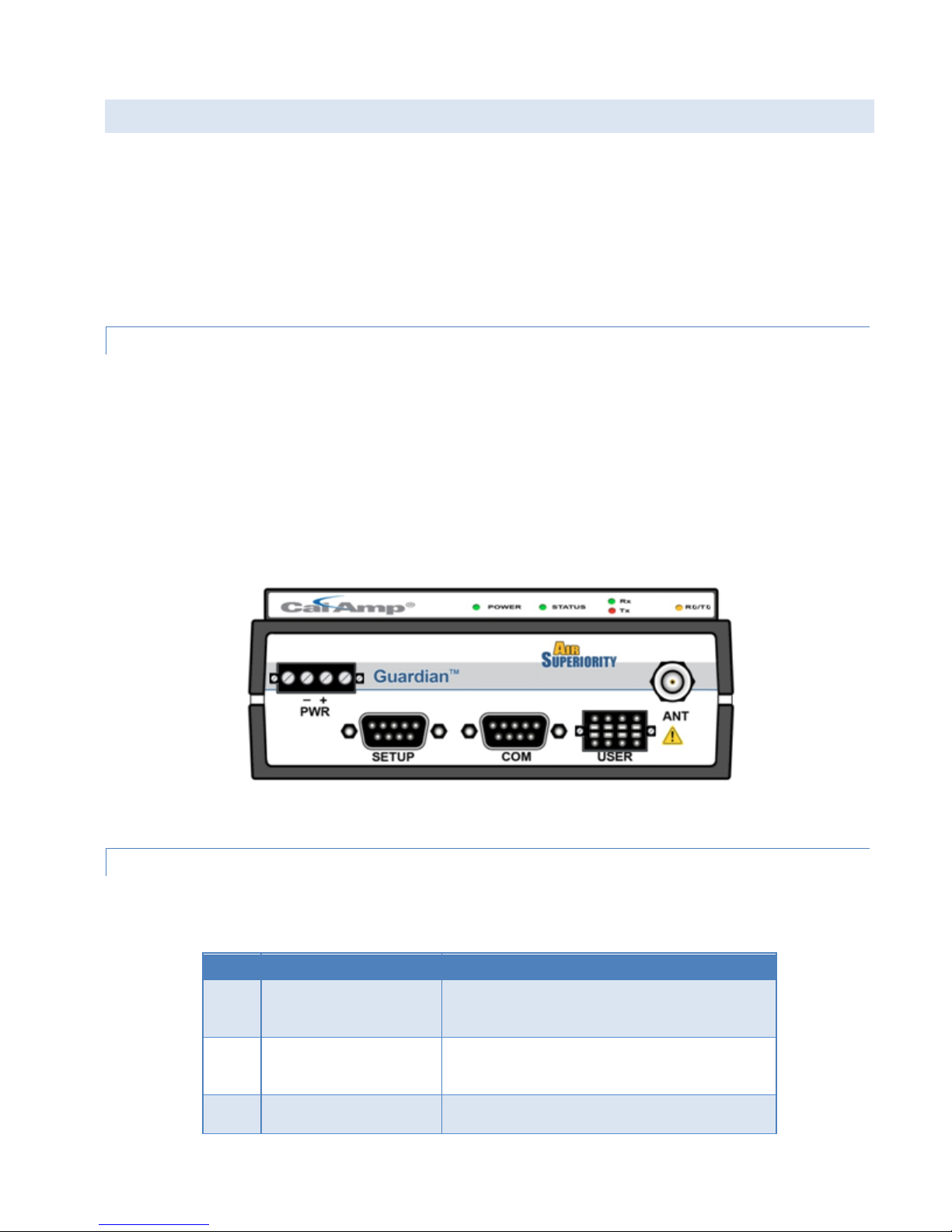
1.4.1 FRONT PANEL
The front panel has the following connections.
• (1) 8-Pin user interface block connector
• (1) 50-ohm TNC female Antenna connector
• (1) 50-ohm SMA female receive antenna connector (Dual-Port and Full-Duplex models only)
• (1) Right-angle power connector (10-30 VDC)
• (2) DE-9F RS-232 ports
• For Dual-Port or Full-Duplex Guardian connections, see Section 1.4.6.
Figure 1 Guardian Front Panel
1.4.2 LED PANEL
The LED panel has five Tri-Color LEDs. The functionality of each LED is shown in the following table.
Table 2 Guardian LED Functionality
Amber (Solid or Blinking)
Red
Guardian is programming
Guardian has a fault condition, check unit status
Guardian™ Serial Modem or Analog Radio for Licensed Spectrum PN 001-5006-000 Rev. 3 | Page 3
Page 11
LED
Color
Definition
Tx
Red
Blinking Amber
Off
Transmitting data
RD/TD
Green
Red
Receive data is being sent out of the port
Transmit data is being received by the port
Contact
Signal Name
1,2
1,2
1,2
1,2
1
The unit wants to transmit, but is inhibited
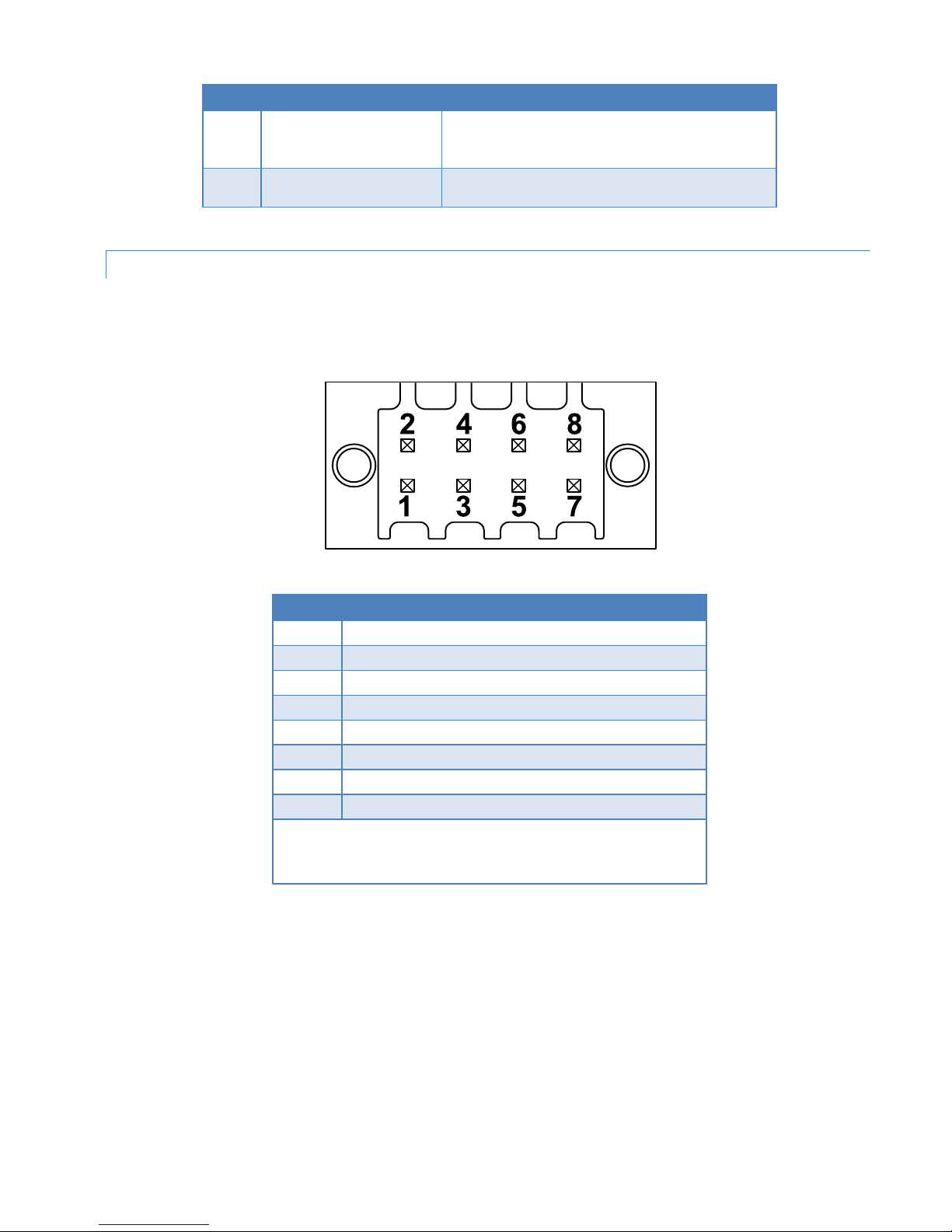
1.4.3 USER INTERFACE PORT
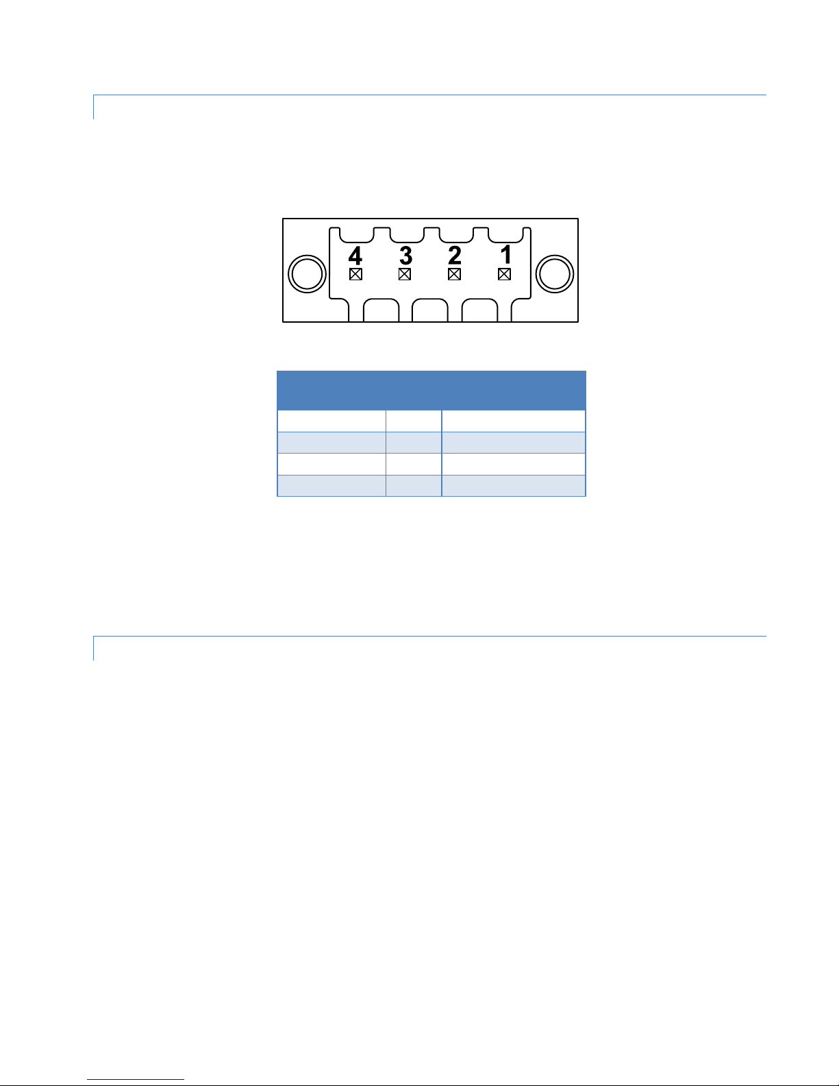
The user interface port is an 8 pin block receptacle, programmable to work with 1.8V to 5V levels. The following table
shows pin-out descriptions for the User port.
Figure 2 User Interface Port Connector
Table 3 Pin-Out for User Connector
1 Tx Audio in OR RS-485/422 RxB/RxD+ (input)
2 Rx Audio Out OR RS-485/422 TxB/TxD+ (output)
3 PTT OR RS-485/422 RxA/RxD- (input)
4 RSSI Out OR RS-485/422 TxA/TxD- (output)
5 Ground
6 Configuration Select 1 (internally pulled high)
7 Configuration Select 3 (internally pulled high)
8 Configuration Select 2 (internally pulled high)
When RS-422 or RS-485 is configured.
2
For Half-Duplex (2 wire) connections, connect pin 1 (RxB/RxD+) to pin
2 (TxB/TxD+) and pin 3 (RxA/RxD-) to pin 4 (TxA/TxD-).
Guardian™ Serial Modem or Analog Radio for Licensed Spectrum PN 001-5006-000 Rev. 3 | Page 4
Page 12
1.4.4 SETUP AND COM PORTS
Contact
Signal Name
Signal Direction
1
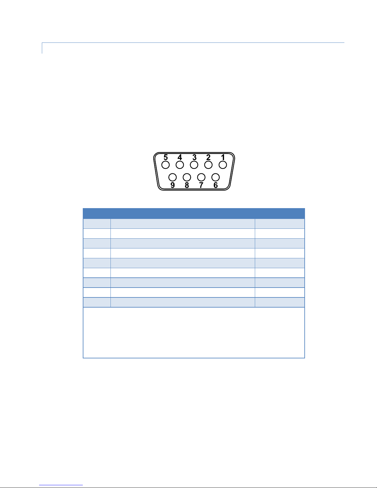
The SETUP and COM serial connections are DE-9F RS-232 ports. The pin-out for the SETUP and COM ports are shown in
the table below.
Serial port considerations
• Guardian radio modem SETUP and COM ports are Data Communication Equipment (DCE) devices
• In general, equipment connected to the Guardian’s SETUP / COM serial port is Data Terminal Equipment (DTE) and a
straight-through cable is recommended.
Note: If a DCE device is connected to the Guardian SETUP/COM port, a null cable/adapter is required.
Figure 3 Guardian SETUP / COM port Contact Numbering for Pin-Out
Table 4 Pin-Out for DCE SETUP and COM Port, 9 Contact DE-9 Connector
1 Data Carrier Detect (DCD)1 DTE ← DCE
2 Receive Data (RxD) DTE ← DCE
3 Transmit Data (TxD) DTE → DCE
4 Data Terminal Ready (DTR) DTE → DCE
5 Signal Ground (GND) DTE ― DCE
6 Data Set Ready (DSR)2 DTE ← DCE
7 Ready To Send (RTS)3 DTE → DCE
8 Clear To Send (CTS)4 DTE ← DCE
9 Ring Indicator (RI)5 DTE ― DCE
DCD is asserted on the COM port when a carrier is received. It is unused on the Setup port.
2
Always asserted with DTR applied.
3
RTS on the COM port requests transmitter key up in RTS/CTS activation mode. It is unused on
the Setup port.
4
CTS will be asserted when data can be sent on the COM port. It is unused on the Setup port.
5
Future use.
Guardian™ Serial Modem or Analog Radio for Licensed Spectrum PN 001-5006-000 Rev. 3 | Page 5
Page 13
1.4.5 POWER CONNECTOR
Contact number
Color
Description
2
Red
Positive (10-30) VDC
The Guardian is supplied with a right-angle power connector (10-30 VDC). The table below shows the pin-out of the
power connector.
Figure 4 Power Connector
Table 5 Pin-Out of the Power Connector
(Left to Right)
4 Fan Power Output (5V)
3 Black Ground
1 White Enable — See Note
Note: The white Enable line must be tied to the red positive lead of the connector for the Guardian to power up.
Bringing the Enable line low is a request for the unit to power down. If the unit is writing to any non-volatile memory, it
will complete the operation before powering down. It is highly recommended that you use the Enable line to power up
and power down the radio.
1.4.6 ANTENNA CONNECTOR
The standard Guardian has a 50-Ohm TNC female antenna connector. This connection functions for both transmit and
receive.
Warning: See 2.5 Selecting Antenna and Lightning Arrestor Combinations for information about types of lightning
arrestors to not use and good design practices to use when selecting a lightning arrestor for use with an antenna.
The Dual-Port and Full-Duplex Guardian have a 50-Ohm TNC female antenna connector functioning for transmit (only)
and a 50-Ohm SMA female antenna connector functioning for receive (only). The separate receive antenna connector
allows for unique customer applications that require additional receive filtering, external PA(s), and other options.
Warning: The transmit antenna port must not be connected directly to the receive antenna port of the Dual Port or
Full Duplex Guardian. Excessive power into the receive antenna port will damage the radio. Input power to the
receiver should not exceed 17 dBm (50 mW).
To reduce potential interference, the antenna type and its gain should be chosen to ensure the effective isotropic
radiated power (EIRP) is not more than required for successful communication.
Guardian™ Serial Modem or Analog Radio for Licensed Spectrum PN 001-5006-000 Rev. 3 | Page 6
Page 14
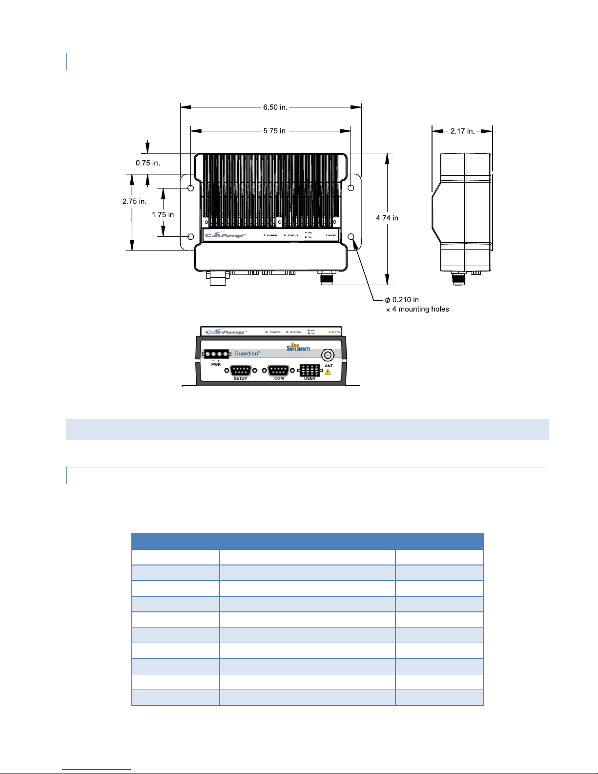
1.4.7 CHASSIS DIMENSIONS
Model Number
Description
Frequency Range
Figure 5 Dimensions of the Guardian Chassis and Mounting Plate
1.5 PART NUMBERS AND AVAILABILITY
1.5.1 GUARDIAN RADIO
The following table provides a breakdown of the Guardian part number 140-50X6-Y0Z.
Table 6 Part Number Breakdown
140-5016-500 Standard VHF Guardian 100 136 - 174 MHz
140-5026-500 Standard VHF Guardian 200 215 - 240 MHz
140-5046-300 Standard UHF Guardian 400 Range 3 406.1 - 470 MHz
140-5046-500 Standard UHF Guardian 400 Range 5 450 - 512 MHz
140-5096-500 Standard 900 MHz Guardian 900 928 - 960 MHz
140-5016-501 Full Duplex VHF Guardian 100 136 – 174 MHz
140-5026-501 Full Duplex VHF Guardian 200 215 – 240 MHz
140-5046-301 Full Duplex UHF Guardian 400 Range 3 406.1 - 470 MHz
140-5046-501 Full Duplex UHF Guardian 400 Range 5 450 - 512 MHz
140-5096-501 Dual-Port 900 MHz Guardian 900* 928 - 960 MHz
* Dual-Port 900 MHz Guardian does not support Full-Duplex operation.
Guardian™ Serial Modem or Analog Radio for Licensed Spectrum PN 001-5006-000 Rev. 3 | Page 7
Page 15
1.5.2 ACCESSORIES AND OPTIONS
Description
Part Number
Description
Part Number
Description
Part Number
Field Installed Guardian Fan Kit
150-5008-002
Length
Connectors
Type
Part Number
The following tables list Guardian Demo Kits and standard accessories tested and approved for use with the Guardian.
Table 7 Guardian Demo Kits
Guardian 100 Demo Kit* – VHF – 136-174 MHz 250-5016-500
Guardian 200 Demo Kit* – VHF 200 – 215-240 MHz 250-5026-500
Guardian 400 Demo Kit* – UHF - 406 – 470 MHz 250-5046-300
Guardian 400 Demo Kit* – UHF – 450 – 512 MHz 250-5046-500
Guardian 900 Demo Kit* – 900 – 928 – 960 MHz 250-5096-500
* The Guardian Demo Kit includes two of each of the following: Guardians, rubber-duck
antennas, adapters, attenuators, power cables, and power supplies.
Table 8 Guardian Power Cable
Guardian Power Cable 897-5008-010
Table 9 Guardian Fan Kits
Factory Installed Guardian Fan Kit 150-5008-001
Table 10 Coaxial Adapter Cables
18 inches TNC-Male to N-Male RG-400 250-0697-103
48 inches TNC-Male to N-Male RG-400 250-0697-104
72 inches TNC-Male to N-Male RG-400 250-0697-105
18 inches TNC-Male to N-Female RG-400 250-0697-106
Guardian™ Serial Modem or Analog Radio for Licensed Spectrum PN 001-5006-000 Rev. 3 | Page 8
Page 16
2 SYSTEM ARCHITECTURE AND NETWORK PLANNING
This section briefly discusses network architecture (including basic network types), interfacing modems and DTE, data
protocols for efficient channel operation, addressing, and repeaters.
Guardian is designed to replace wire lines in SCADA, telemetry and control applications. The RS-232 serial port allows
direct connection to Programmable Logic Controllers (PLCs) or Remote Terminal Units (RTUs). A SCADA system is
defined as one or more centralized control sites used to monitor and control remote field devices over wide areas. For
example, a regional utility may monitor and control networks over an entire metropolitan area. Industry sectors with
SCADA systems include energy utilities, water and wastewater utilities, and environmental groups.
The Guardian is intended for use in the Industrial Monitoring and SCADA market. The range of the Guardian is
dependent on terrain, RF (radio frequency) path obstacles, and antenna system design. This section provides tips for
selecting an appropriate site, choosing an antenna system, and reducing the chance of harmful interference.
2.1 SINGLE COVERAGE AREA
In a network topology with only a single coverage area (all units can talk to one another directly), there are several
common system configurations.
The most common is for one unit to be designated as a master and the rest designated as remotes. Another system
configuration is Report-by-Exception.
2.2 NETWORK ARCHITECTURE
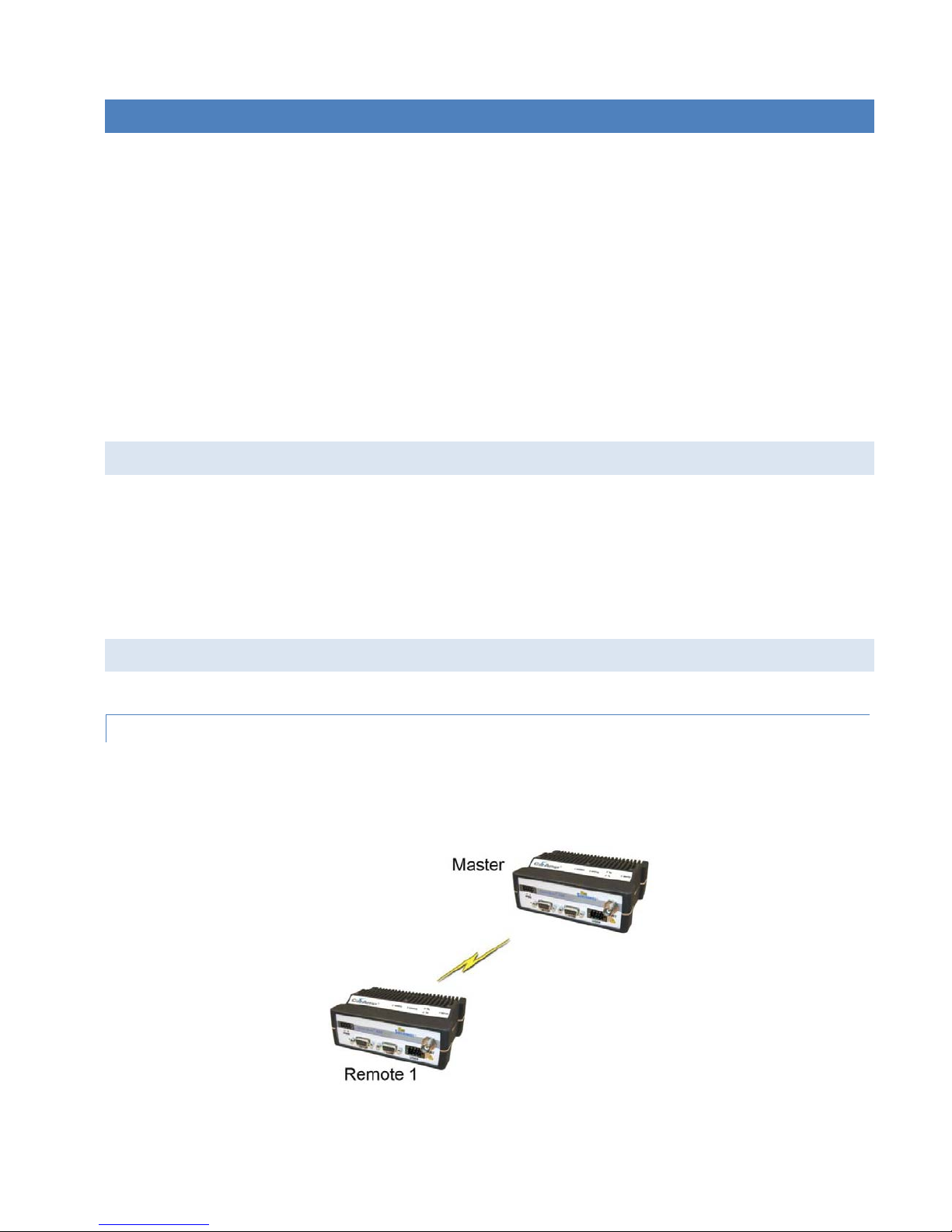
2.2.1 POINT-TO-POINT
A point-to-point network is the most simple of all networks, and may be used for connecting a pair of PCs, a host
computer and a terminal, a SCADA polling master and one remote, or a wide variety of other networking applications.
Figure 6 Point-to-Point Network
Guardian™ Serial Modem or Analog Radio for Licensed Spectrum PN 001-5006-000 Rev. 3 | Page 9
Page 17
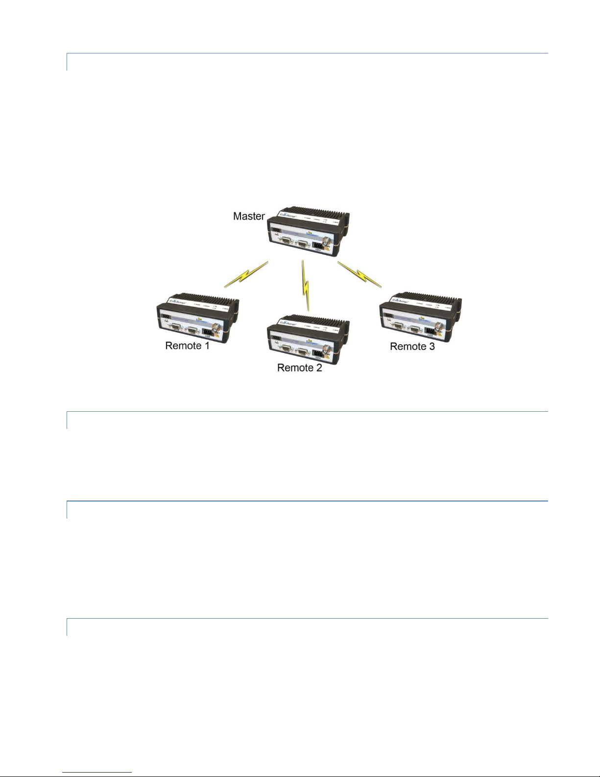
2.2.2 POINT-TO-MULTIPOINT
A Point-to-Multipoint network is a common network type used in SCADA or other polling systems. The single polling
master station communicates with any number of remotes and controls the network by issuing polls and waiting for
remote responses. Individual PLC/RTU remotes manage addressing and respond when their individual addresses are
queried. PLC/RTU unit addresses are maintained in a scanning list stored in the host program or master terminal device
at the SCADA host site. Communications equipment is transparent and does not interact with specific remotes; all data
is coupled to the host on a single data line (such a network is commonly used with synchronous radio modems and
asynchronous radio modems).
Figure 7 Point to Multipoint Network
2.2.3 MULTIPLE POINT-TO-POINT
A multiple point-to-point is similar to the point-to-multipoint system except the SCADA host has multiple serial ports
that are directed to different geographic areas in the SCADA system.
2.2.4 PEER-TO- PEER
A Peer-to-Peer network is generally used for device to device communications among a number of stations. This
network requires full addressing capability on the part of the data equipment (DTE). If the distances involved for any
link or links are too great for a single radio hop, they can be extended by means of repeaters without affecting the basic
network design.
2.2.5 STORE AND FORWARD
Store and forward is a common technique where a data transmission is sent from one device to a receiving device but
first passes through a relaying device. The device is typically an RTU or PLC used by the message service to store the
received message then it transmits the message to the intended recipient.
Guardian™ Serial Modem or Analog Radio for Licensed Spectrum PN 001-5006-000 Rev. 3 | Page 10
Page 18

2.2.6 NETWORK USING A GUARDIAN FOR ONLINE DIAGNOSTICS
The Network Using a Guardian for Online Diagnostics configuration has the following characteristics.
• Master station may be full duplex (duplexer dual antennas required), half duplex or simplex.
• Accumulated online diagnostics are available at a monitoring site (monitoring site must be in range of all remotes).
• Online Diagnostics are available in real time at the monitoring site.
• Remote Offline Diagnostics, statistics, and control are available from the monitoring site by temporarily disabling
network activity (best if using a Master Station Antenna System).
Online diagnostics are accumulated in the monitoring Guardian for the last 15 stations heard. This information may be
viewed using the Online Diagnostics utility. For larger networks, the Guardian can output raw diagnostic data through
the Setup port which may be interpreted for network management by the Field Programming Software Online
Diagnostics utility or by a user-supplied software program. Contact your sales representatives for more information.
2.3 UNDERSTANDING RF PATH REQUIREMENTS
Radio waves are propagated when electrical energy produced by a radio transmitter is converted into magnetic energy
by an antenna. Magnetic waves travel through space. The receiving antenna intercepts a very small amount of this
magnetic energy and converts it back into electrical energy that is amplified by the radio receiver. The energy received
by the receiver is called the Received Signal Strength Indication (RSSI) and is measured in dBm.
A radio modem requires a minimum amount of received RF signal to operate reliably and provide adequate data
throughput. This is the radio’s receiver sensitivity. In most cases, spectrum regulators will define or limit the amount of
signal that can be transmitted and it will be noted on the FCC license. This is the effective isotropic radiated power
(EIRP). Transmitted power decays with distance and other factors as it moves away from the transmitting antenna.
2.4 SITE SELECTION AND SITE SURVEY
2.4.1 SITE SELECTION
For a successful installation, careful thought must be given to selecting the site for each radio. These requirements can
be quickly determined in most cases. Suitable sites should provide the following.
• Protection from direct weather exposure.
• A source of adequate and stable primary power
• Suitable entrances for antenna, interface, or other cabling.
• Antenna location with an unobstructed transmission path to all remote radios in the system.
Guardian™ Serial Modem or Analog Radio for Licensed Spectrum PN 001-5006-000 Rev. 3 | Page 11
Page 19

2.4.2 SITE SURVEY
A Site Survey is an RF propagation study of the RF path between two points or between one point and multiple points.
UHF radio signals travel primarily by line of sight and obstructions between the sending and receiving stations will
affect system performance. Signal propagation is also affected by attenuation from obstructions such as terrain,
foliage, or buildings in the transmission path. A Site Survey is recommended for most projects to determine the optimal
RF paths for each link. This is especially true when more than one RF coverage area is required. A Site Survey will
determine the best unit location for the Relay Points.
2.5 SELECTING ANTENNA AND LIGHTNING ARRESTOR COMBINATIONS
RF engineers and installers have seen many types of radio installations over the years, and they know there are certain
details that must not be overlooked at any installation. Most radio installations contain some form of lightning
protection. However, the wrong combination of antenna and lightning arrestor can create high voltage transients on
the radio’s antenna port having devastating impacts on the life and reliability of modern day radio equipment.
2.5.1 LIGHTNING ARRESTOR OVERVIEW
Lightning arrestors can take many forms. But some of the most common lightning arrestors use gas discharge tubes
that turn on when the voltage across their terminals exceeds the specified threshold. Under normal conditions, these
devices have very high impedance and no current flows through the device. When the turn on voltage threshold is
exceeded, the gas discharge tube turns on instantaneously and becomes a short.
This functionality works well to limit the magnitude of a transient from a nearby lightning discharge. However, it can
have very negative consequences if a gas discharge lightning arrestor is used with the wrong antenna.
2.5.2 ANTENNA OVERVIEW
Antennas can come in just about any shape or size. However, there is one parameter, in particular, that the system
designer should not overlook, especially if the radio installation uses gas discharge tube lightning arrestors. The
parameter is the DC grounding of the active element in the antenna.
A DC grounded antenna will measure 0 ohms from the active element to ground when tested with an ohm-meter. One
way to test this is to connect the ohm-meter from the center conductor to ground of the RF cable that is attached
directly to the antenna. This will read as a short for a DC grounded antenna, and as an open for a non DC grounded
antenna. Note: Some antenna datasheets are misleading and will indicate the antenna is DC grounded. However, the
datasheet may be referring to the body of the antenna and not necessarily the active element. For this reason, it is best
to measure the antenna you plan to use to verify the active element is DC grounded.
2.5.3 THE WRONG COMBINATION
The combination of a DC open antenna and a DC blocked gas discharge tube lightning arrestor creates a situation
where static charge can build up slowly on the active element of the antenna. Static charge can be created by wind
Guardian™ Serial Modem or Analog Radio for Licensed Spectrum PN 001-5006-000 Rev. 3 | Page 12
Page 20
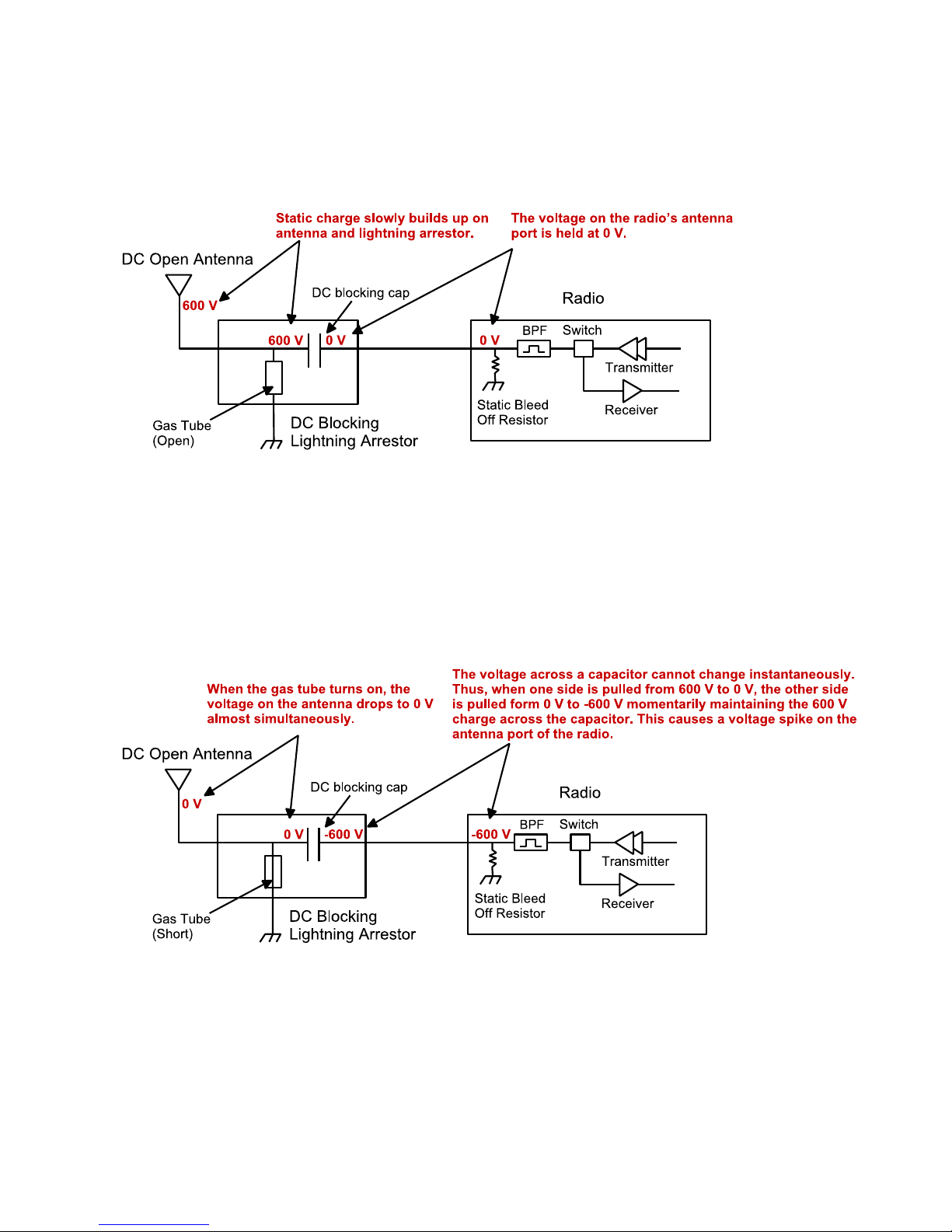
blowing across the antenna, precipitation hitting the active element, or other environmental causes. As static charge
builds up on the antenna’s active element, over a period of minutes or even hours, the DC blocking capacitor inside the
lightning arrestor is charged.
Figure 8 Voltage buildup due to static
When the voltage exceeds 600V (the breakdown voltage for IS-B50LN series PolyPhasers), the gas discharge tube turns
on and the antenna side of the DC blocking capacitor is immediately pulled from 600V to 0V. Since the lighting
arrestor’s capacitor was charged to 600V, that charge must dissipate through the radio. As the capacitor discharges, a
large negative transient is created on the antenna port of the radio. Positive transients can also be created if the static
charge buildup on the antenna has a negative polarity.
Figure 9 Voltage Transient immediately after the gas tube turns on
During testing, transients were measured on the antenna port of CalAmp’s Viper at voltage levels up to +/-280V. These
voltage transients often have high frequency content that can easily pass through any filtering in the radio and damage
components in the transmitter and receiver circuitry.
Guardian™ Serial Modem or Analog Radio for Licensed Spectrum PN 001-5006-000 Rev. 3 | Page 13
Page 21

2.5.4 GOOD DESIGN PRACTICES
There are two relatively easy ways to avoid creating large transients due to static buildup on an antenna and the
subsequent firing of the gas discharge tube in the lightning arrestor. Following either or both of the recommendations
below will eliminate this potential problem.
1. Use antennas with a DC grounded active element. Antennas can easily be tested, by using an ohm meter, to
measure the resistance from the center conductor to the ground of the RF cable that is directly attached to the
antenna. The ohm-meter should indicate a short. (Some antenna designs, such as folded dipole or folded dipole Yagi
antennas, inherently have a DC ground on the active element due to the nature of the antenna design.)
2. Use a lightning arrestor that does not have a gas discharge tube. PolyPhaser makes several DC blocked lightning
arrestors that have an inductor to ground instead of a gas tube. These lightning arrestors will not allow the static to
build up on the antenna, and there is no gas tube that can trigger causing a transient into the antenna port of the
radio. The following lightning arrestors, manufactured by PolyPhaser, have inductors to ground instead of gas tubes:
a. PolyPhaser Part Number: VHF50HN Frequency Range: 100MHz - 512MHz, 750W
b. PolyPhaser Part Number: TSX-NFF Frequency Range: 700MHz - 2.7GHz, 750W
Tip: Lightning arrestors that use gas tubes will normally specify a “Turn-On Voltage” in the data sheet. If you see this
specification in the datasheet, it is very likely that the lightning arrestor has a gas discharge tube. If you are still unsure,
contact the manufacturer.
2.6 SELECTING ANTENNA AND FEEDLINE
The Guardian can be used with a variety of antenna types. The exact style used depends on the physical size and layout
of a system. The Guardian device has been tested and approved with antennas having a maximum gain of 10 dBi.
2.6.1 ANTENNA GAIN
Antenna gain is usually measured in comparison to a dipole. A dipole acts much like the filament of a flashlight bulb: it
radiates energy in almost all directions. One bulb like this would provide very dim room lighting. Add a reflector
capable of concentrating all the energy into a narrow angle of radiation and you have a flashlight. Within that bright
spot on the wall, the light might be a thousand times greater than it would be without the reflector. The resulting bulbreflector combination has a gain of 1000, or 30 dB, compared to the bulb alone. Gain can be achieved by concentrating
the energy both vertically and horizontally, as in the case of the flashlight and Yagi antenna. Gain can be also be
achieved by reducing the vertical angle of radiation, leaving the horizontal alone. In this case, the antenna will radiate
equally in all horizontal directions, but will take energy that otherwise would have gone skywards and use it to increase
the horizontal radiation.
The required antenna impedance is 50 ohms. To reduce potential radio interference, the antenna type and its gain
should be chosen to ensure the effective isotropic radiated power (EIRP) is not more than required for successful
communication.
A number of FCC-approved antennas have been tested for use with the Guardian. Similar antenna types from other
manufacturers are equally acceptable. It is important to follow the manufacturer’s recommended installation
procedures and instructions when mounting any antenna.
Guardian™ Serial Modem or Analog Radio for Licensed Spectrum PN 001-5006-000 Rev. 3 | Page 14
Page 22
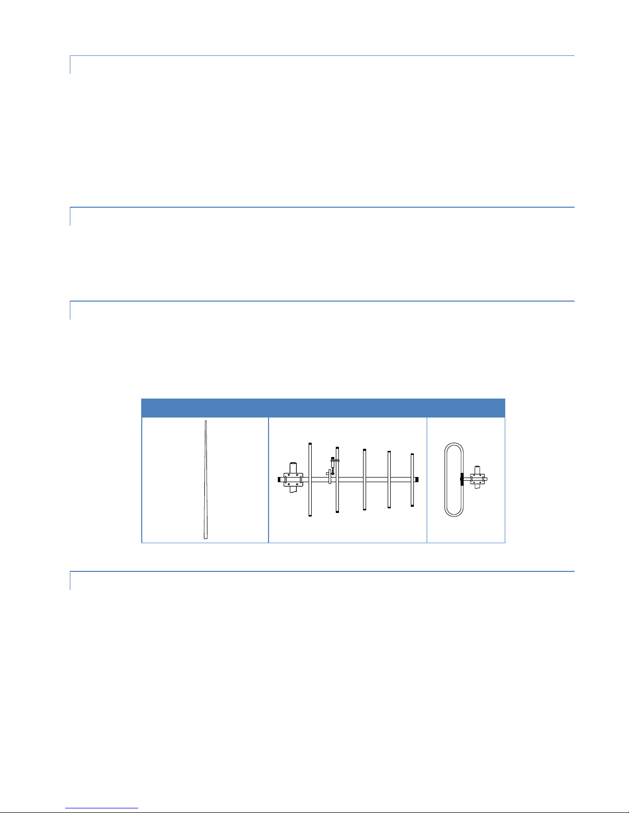
2.6.2 OMNI-DIRECTIONAL ANTENNA
Omni (Vertical Collinear)
Yagi
Vertical Dipole
In general, an omnidirectional antenna should be used at a master station and Relay Points. This allows equal coverage
to all of the remote locations. Omni directional antennas are designed to radiate the RF signal in a 360- degree pattern
around the antenna. Short range antennas such as folded dipoles and ground independent whips are used to radiate
the signal in a ball shaped pattern while high gain omni antennas, such as a collinear antenna, compress the RF
radiation sphere into the horizontal plane to provide a relatively flat disc shaped pattern that travels further because
more of the energy is radiated in the horizontal plane.
2.6.3 YAGI ANTENNA
At remote locations (not used as a Relay Point), a directional Yagi is generally recommended to minimize interference
to and from other users.
2.6.4 VERTICAL DIPOLES
Vertical dipoles are very often mounted in pairs, or sometimes in groups of three to four, to achieve even coverage and
to increase gain. The vertical collinear antenna usually consists of several elements stacked one above the other to
achieve similar results.
Table 11 Antenna Types
2.6.5 FEEDLINE
The choice of feedline should be carefully considered. Poor quality coaxial cables should be avoided, as they will
degrade system performance for both transmission and reception. The cable should be kept as short as possible to
minimize signal loss. See the following table for a list of feedline recommendations.
Guardian™ Serial Modem or Analog Radio for Licensed Spectrum PN 001-5006-000 Rev. 3 | Page 15
Page 23
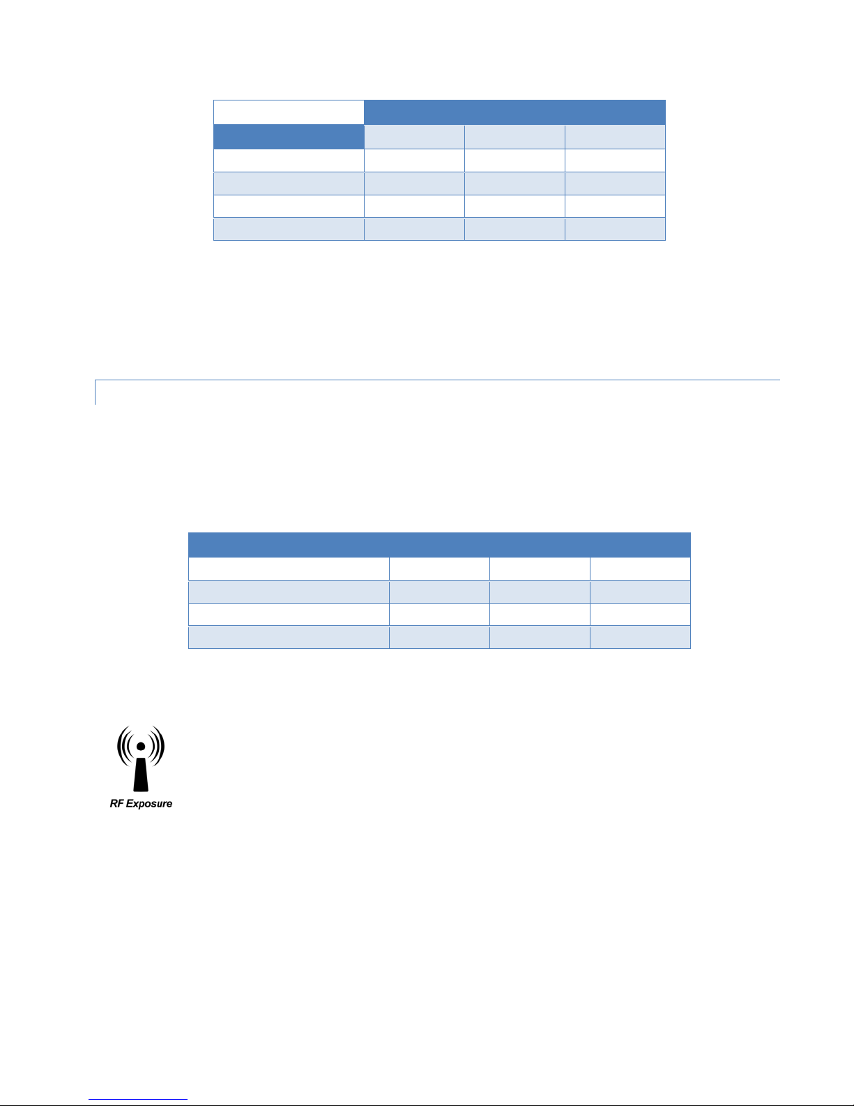
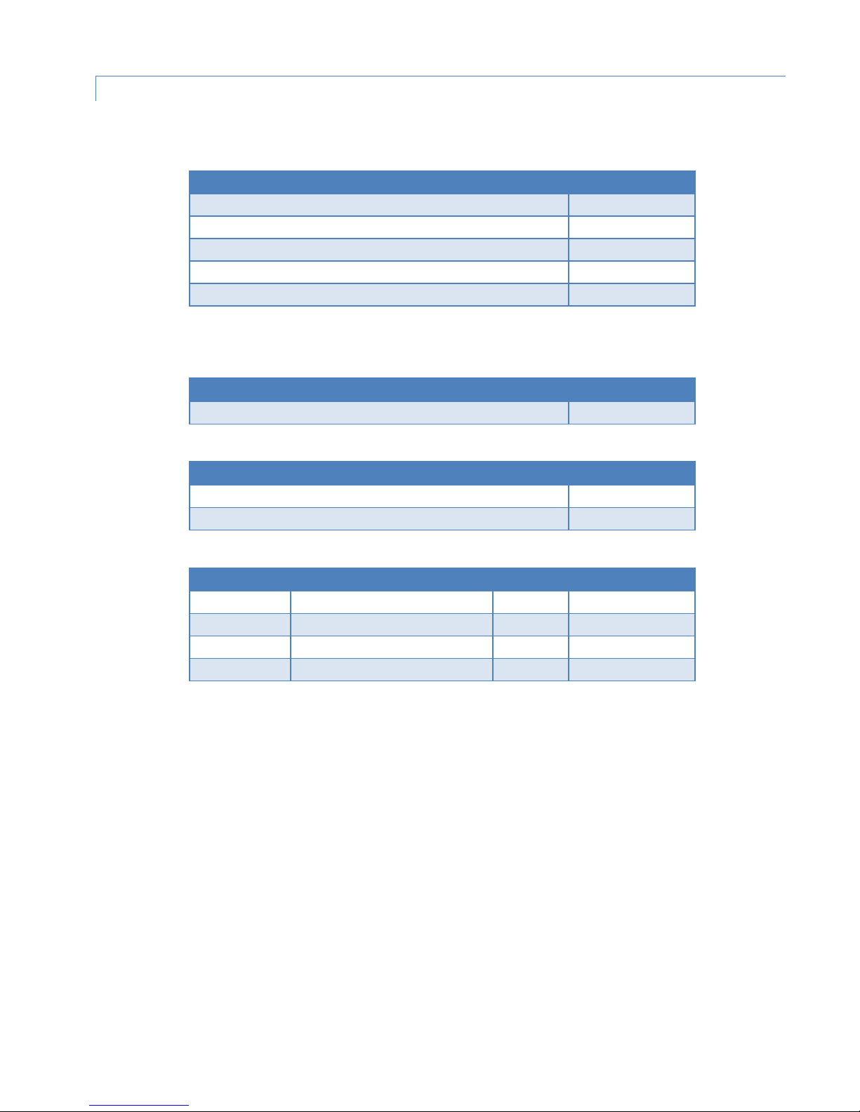
Table 12 Transmission Loss (per 100 Feet)
Frequency Range
Cable Type
VHF
UHF
900 MHz
LMR-400
1.5 dB
2.7 dB
3.9 dB
1/2” Heliax
0.68 dB
1.51 dB
2.09 dB
7/8” Heliax
0.37 dB
0.83 dB
1.18 dB
1-5/8” Heliax
0.22 dB
0.51 db
0.69 dB
Minimum Safety Distance
Antenna Gain
5 dBi
10 dBi
15 dBi
VHF at maximum power
123 cm
218.8 cm
389 cm
UHF at maximum power
105.7 cm
188 cm
334.4 cm
900 MHz at maximum power
63.8 cm
115 cm
201.7 cm
Outside cable connections should have a weather kit applied to each connection to prevent moisture. Feedline
connections should be routinely inspected to minimize signal loss through the connection. A 3 dB loss in signal strength
due to cable loss and/or bad connections represents a 50% reduction in signal strength.
2.6.6 RF EXPOSURE COMPLIANCE REQUIREMENTS
The Guardian radio is intended for use in the Industrial Monitoring and Control and SCADA markets. The Guardian unit
must be professionally installed and must ensure a minimum separation distance listed in the table below between the
radiating structure and any person. An antenna mounted on a pole or tower is the typical installation and in rare
instances, a 1/2-wave whip antenna is used.
Table 13 RF Exposure Compliance Minimum Safety Distances
Note: It is the responsibility of the user to guarantee compliance with the FCC MPE regulations when
operating this device in a way other than described above.
The Guardian serial radio uses a low power radio frequency transmitter. The concentrated energy from
an antenna may pose a health hazard. People should not be in front of the antenna when the
transmitter is operating.
The installer of this equipment must ensure the antenna is located or pointed such that it does not emit an RF field in
excess of Health Canada limits for the general population. Recommended safety guidelines for the human exposure to
radio frequency electromagnetic energy are contained in the Canadian Safety Code 6 (available from Health Canada)
and the Federal Communications Commission (FCC) Bulletin 65.
Any changes or modifications not expressly approved by the party responsible for compliance (in the country where
used) could void the user’s authority to operate the equipment.
Guardian™ Serial Modem or Analog Radio for Licensed Spectrum PN 001-5006-000 Rev. 3 | Page 16
Page 24

2.7 TERRAIN AND SIGNAL STRENGTH
RSSI
Reliability
A line of sight (LOS) path between stations is highly desirable and provides the most reliable communications link in all
cases. A line of sight path can often be achieved by mounting each station antenna on a tower or other elevated
structure that raises it high enough to clear surrounding terrain and other obstructions.
The requirement for a clear transmission path depends on the distance to be covered by the system. If the system is to
cover a limited distance, say 3-5 miles, then some obstructions in the transmission path may be tolerable. For longerrange systems, any obstruction could compromise the performance of the system, or block transmission entirely.
The signal strength (RSSI) at the receiver must exceed the receiver sensitivity by an amount known as the fade margin
to provide reliable operation under various conditions. Fade margin (expressed in dB) is the maximum tolerable
reduction in received signal strength, which still provides an acceptable signal quality. This compensates for reduced
signal strength due to multi-path, slight antenna movement or changing atmospheric losses. CalAmp recommends a 30
dB fade margin for most projects. The following table shows the RSSI versus Reliability.
Table 14 RSSI Reliability
-100 dBm Approximately 50% reliability. Fading may cause frequent data loss.
-90 dBm Approximately 90% reliability. Fading will cause occasional data loss
-80 dBm Approximately 99% reliability. Reasonable tolerance to most fading.
-70dBm Approximately 99.9% reliability with high tolerance to fading.
2.8 RADIO INTERFERENCE
Interference is possible in any radio system. However, since the Guardian is designed for use in a licensed system,
interference is less likely because geographic location and existing operating frequencies are normally taken into
account when allocating frequencies.
The risk of interference can be further reduced through prudent system design and configuration. Allow adequate
separation between frequencies and radio systems. Keep the following points in mind when setting up your radio
system.
a. Systems installed in lightly populated areas are least likely to encounter interference, while those in urban and
suburban areas are more likely to be affected by other devices.
b. Directional antennas should be used at the remote end of the link. They confine the transmission and reception
pattern to a comparatively narrow beam, which minimizes interference to and from stations located outside the
pattern.
c. If interference is suspected from another system, it may be helpful to use antenna polarization opposite to the
interfering system’s antennas. An additional 20 dB (or more) of attenuation to interference can be achieved by
using opposite antenna polarization.
d. Check with your CalAmp sales representative or CalAmp Technical Services for additional options. The Technical
Services group has qualified personnel to help resolve your RF issues.
Guardian™ Serial Modem or Analog Radio for Licensed Spectrum PN 001-5006-000 Rev. 3 | Page 17
Page 25
3 SETUP AND CONFIGURATION
It is easy to set up a Guardian network to verify basic unit operation and experiment with network designs and
configurations.
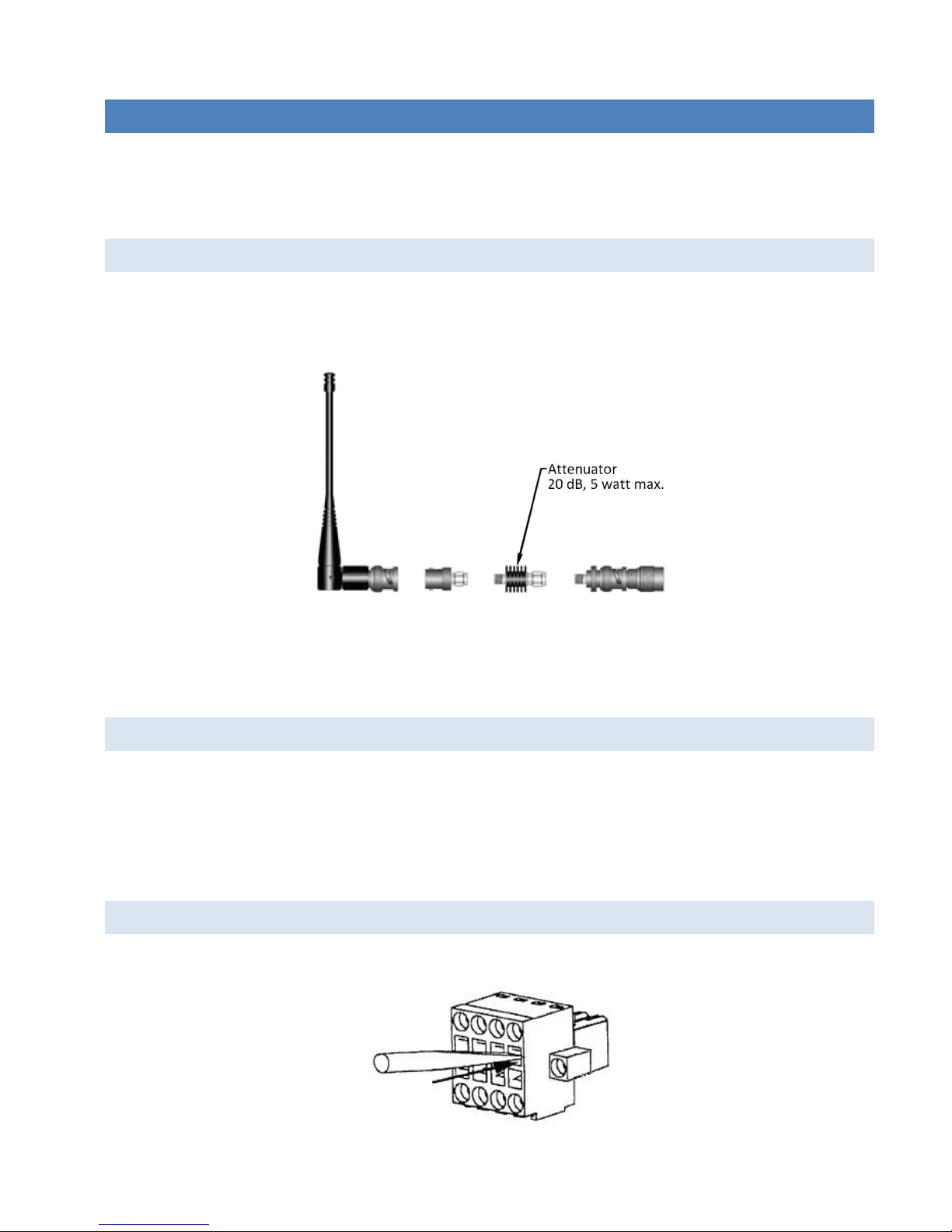
3.1 INSTALL THE ANTENNA
An Rx/Tx antenna is required for basic operation. For demo units only, connect the antenna as shown in the following
figure to provide stable radio communications between demo devices.
Figure 10 Demo Antenna Assembly
Note: It is important to use attenuation between all demo units in the test network to reduce the amount of signal
strength in the test environment.
3.2 MEASURE AND CONNECT PRIMARY POWER
Primary power for the Guardian must be within 10-30 VDC and be capable of providing a minimum of 10 watt supply
for the Tx at 1 W, 40 watt supply for Tx at 5 W, or 60 watt supply for Tx at 10 W. (In Guardian Demo Kits, a power
supply with spring terminals is provided with each unit.) Observe proper polarity when connecting the cables to the
power supply. (White wire must be connected to red wire or B+ supply.)
3.3 INSERTING WIRES INTO USER PORT CONNECTOR
1. Insert 2.5 mm Insertion Tool (CalAmp PN 250-5006-001) into the wire-release slot. Do not twist the Insertion Tool.
Guardian™ Serial Modem or Analog Radio for Licensed Spectrum PN 001-5006-000 Rev. 3 | Page 18
Page 26
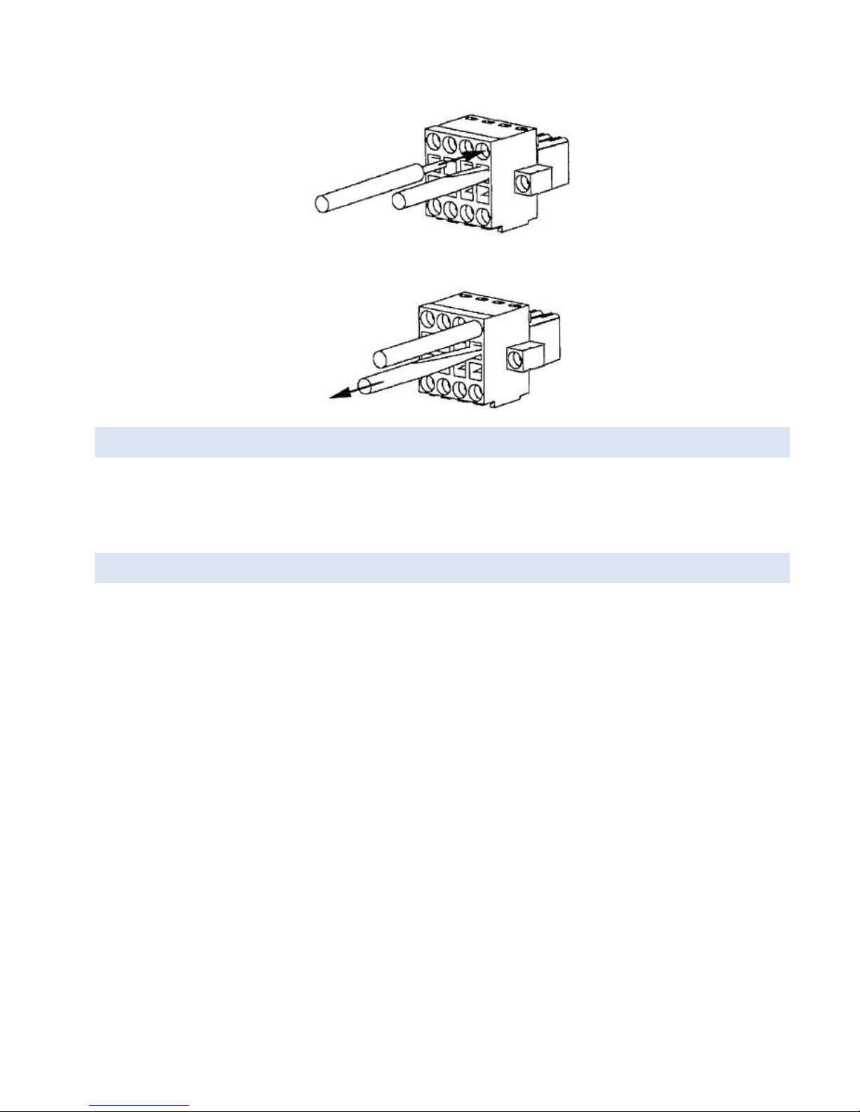
2. Keeping the Insertion Tool in place, insert wire (28 AWG minimum, 18 AWG maximum) into the wire hole.
3. Remove Insertion Tool. Check wire connection.
3.4 CONNECT GUARDIAN TO PROGRAMMING PC
Connection to a Guardian is established through an RS-232 (straight through) or (non-null) cable connected to the
setup port of the Guardian and the COM port of the PC.
3.5 GUARDIAN FIELD PROGRAMMING SOFTWARE
Operating characteristics of the Guardian are configured by the Field Programming Software. Offline Diagnostics and
Online Diagnostics give access to Offline Diagnostics and commands (local and remote) and online diagnostics
monitoring. Programming software is Microsoft Windows® based and requires a Windows 98 or newer operating
system. Context sensitive help and printable help files are provided with this program.
The Guardian requires the use of the Field Programming Software for configuration, adjustment and diagnostics.
Guardian™ Serial Modem or Analog Radio for Licensed Spectrum PN 001-5006-000 Rev. 3 | Page 19
Page 27
4 UNIT STATUS
In addition to unit status information provided by the five tricolor LEDs in the LED Panel, unit status information is also
displayed in the Diagnostics pane of the User Configuration window (page 26 for Modem mode or page 35 for Loader
Mode) of the Guardian Field Programming Software, and is explained in Chapter 5.
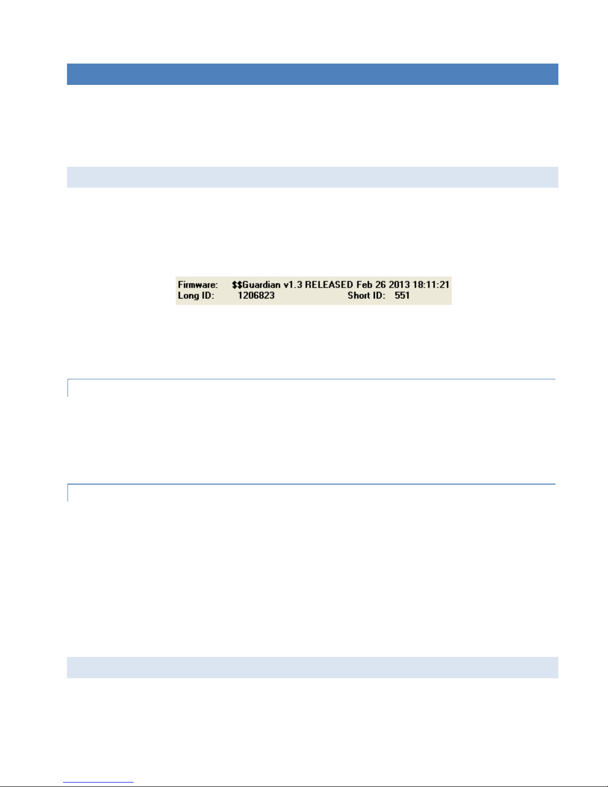
4.1 UNIT IDENTIFICATION AND STATUS
Each Guardian has addressing capability which is used for diagnostics and remote commands only.
The Long ID and Short ID with which each Guardian is configured are displayed directly under the Firmware version
number in the main window of the Guardian Field Programming Software.
Figure 11 Unit Status Information
If this area displays blank (for example when software is first started or initial connection has not been established),
click Version, immediately to the left and the FPS reads this information from the Guardian and it is displayed.
4.1.1 LONG ID NUMBER
This value is assigned at the factory but may be modified using the Field Programming Software. The ID Number is used
to uniquely identify the Guardian for remote commands and Offline Diagnostics. The ID Number may have values
within the range of 1 to 4294967295 but multiples of 1024 should not be used.
4.1.2 SHORT ID
This value (maximum 1023) is the low order 10 bits of the ID Number. It is used to identify online diagnostics only. It
may not be modified directly using the Field Programming Software; it is always derived from the ID Number. All units
within a network should have unique Short ID numbers to avoid ambiguity in Online Diagnostics reports.
The Guardian Field Programming Software may be used to check the value of the Short ID. When setting up a network,
we recommend checking each unit to make sure there is no duplication of Short ID numbers. Duplications may be
resolved by changing the Long ID Number.
If ID Numbers are set within the range of 1 to 1023, the ID Number and the Short ID will always have the same value.
4.2 DIAGNOSTICS
Guardian units continually monitor and report on their environmental and operating conditions.
Guardian™ Serial Modem or Analog Radio for Licensed Spectrum PN 001-5006-000 Rev. 3 | Page 20
Page 28

4.2.1 ONLINE DIAGNOSTICS
Information is automatically sent by each unit at the beginning of every transmission.
Online Diagnostics (statistics) require the use of a network configuration such as that specified in the “Network Using a
Guardian for Online Diagnostics” section 2.2.6. Online diagnostics do not interfere with normal network operation.
Online diagnostics provide four types of information.
• Short ID
• RSSI
• Temperature
• Battery
• Forward Power
• Reverse Power
• Time
See section 5.16 for more about Online Diagnostics in the Field Programming Software.
4.2.2 OFFLINE DIAGNOSTICS
Offline diagnostics are statistics returned in response to a specific request to a particular station. The use of this feature
requires temporary suspension of user network operation. Offline diagnostics provide information that is displayed via
the Offline Diagnostics utility. Offline Diagnostics gather and display the following.
• Battery Voltage
• Analog V
CC
• Temperature
• RSSI Level
• Forward Power
• Reverse Power
• Preamble Good
• Preamble Total
• Preamble DCD
See section 5.15 for more about Offline Diagnostics in the Field Programming Software.
4.2.3 REMOTE COMMANDS
Remote commands that may be sent using the Offline Diagnostics utility include:
• Sample network statistics (monitoring online diagnostics)
• Get statistics (diagnostics)
Guardian™ Serial Modem or Analog Radio for Licensed Spectrum PN 001-5006-000 Rev. 3 | Page 21
Page 29
5 GUARDIAN FIELD PROGRAMMING SOFTWARE
5.1 INTRODUCTION
The Guardian Field Programming Software provides programming and diagnostics for the Guardian wireless modem.
The Field Programming Software allows the user to edit and program user programmable settings, interactively tune
modem and RF parameters, and monitor diagnostic data from the Guardian. See the following figure for the Guardian
Field Programming Software startup window.
Figure 12 Guardian Field Programming Software Startup Window
This manual assumes the Field Programming Software (included with your device) has been installed on the user’s PC
with at least one operational serial COM Port available.
5.2 GUARDIAN PROGRAMMER WINDOW
The following figure displays the main window of the Guardian Programmer software for field programming the
Guardian.
Guardian™ Serial Modem or Analog Radio for Licensed Spectrum PN 001-5006-000 Rev. 3 | Page 22
Page 30
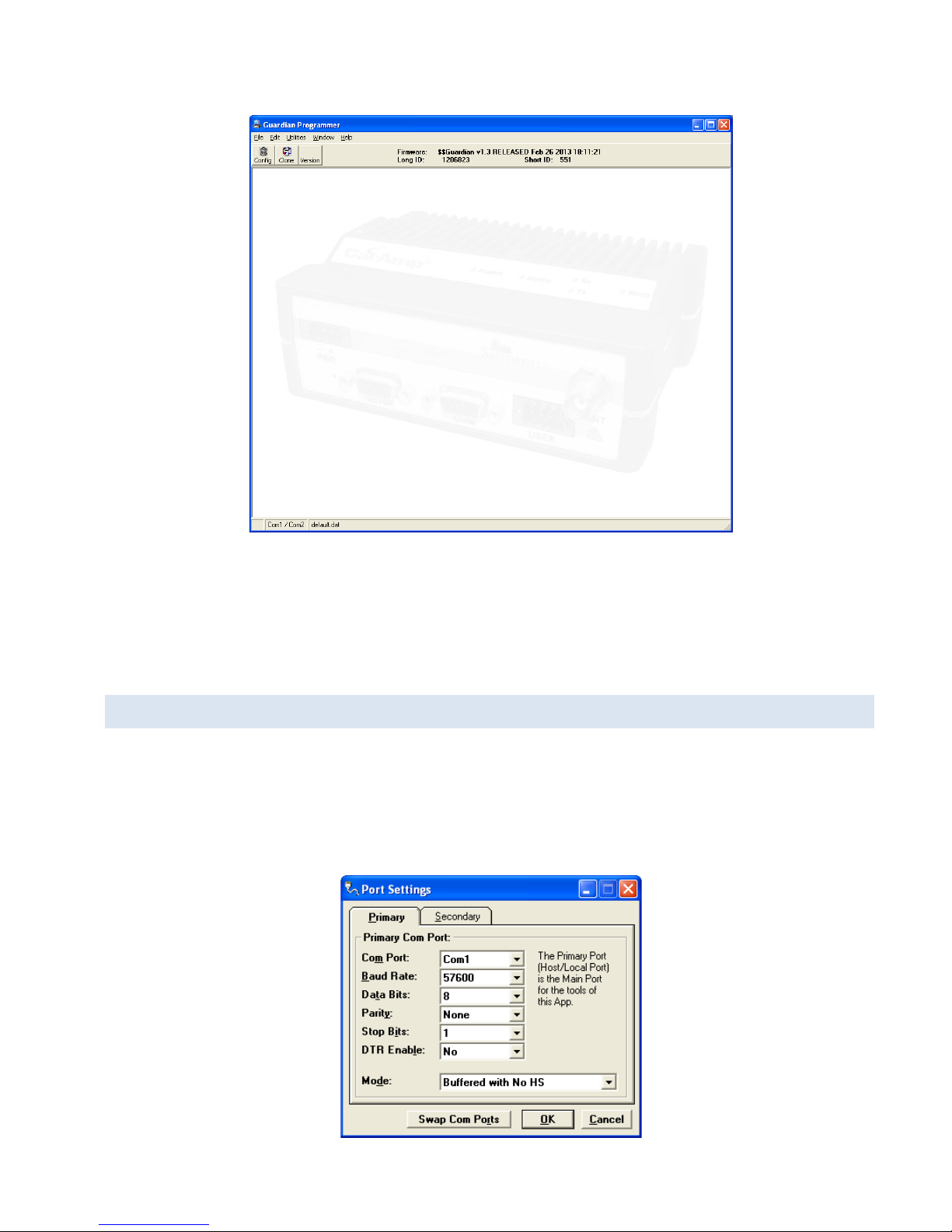
Figure 13 Guardian Programmer Window
Guardian programming is through the PC’s Primary COM Port. Primary and secondary COM ports are configured with
the Field Programming Software. The programming cable (included in the Demo Kit) is connected from the Setup Port
on the Guardian to the PC’s COM port configured as the Primary Port.
5.3 PORT SETTINGS
The Port Settings window of the Field Programming Software is accessed by selecting Port Settings from the Utilities
menu of the main Guardian Programmer window (above). Tabbed panels in the Port Settings window (see the
following figure) are used to configure the PC’s serial COM ports. COM port assignments are displayed in the status bar
at the bottom of the main Guardian Programmer window.
Figure 14 Port Settings Window
Guardian™ Serial Modem or Analog Radio for Licensed Spectrum PN 001-5006-000 Rev. 3 | Page 23
Page 31

COM Port
Mode
Description
Sync/ESC with No HS
Sends data using Sync/byte-stuffing protocol without handshaking.
Buffered with No HS
Sends buffered data without handshaking (this mode required for DOX
operation.) This is the Default.
Sync/Esc with RTS/CTS HS
Sends data using the Sync/Esc byte-stuffing protocol with RTS/CTS
hardware handshaking.
Buffered with RTS/CTS HS
Sends buffered data with RTS/CTS hardware handshaking.
Sync/Esc with Flow Control HS
Sends data using the Sync/Esc byte-stuffing protocol with flow control
handshaking.
Buffered with Flow Control HS
Sends buffered data with flow control hardware handshaking.
Selects COM Port number (1- 32) for Primary and Secondary COM Ports. Default is COM1.
Baud Rate
Selects the communication speed for Primary and Secondary COM Ports. Default is 57600 bps.
Data Bits
Selects number of data bits (7 or 8) transmitted or received for the Primary and Secondary COM Ports. Default is 8.
Parity
Selects transmission or reception of any Parity bits for the Primary and Secondary COM Ports. Default is None.
Stop Bits
Selects number of Stop Bits (1 or 2) transmitted or received for the Primary and Secondary COM Ports. Default is 1.
DTR Enable
Used to assert DTR (Data Terminal Ready) line of the RS-232 Port when the port is open for the Primary and Secondary
COM Ports. Default is NO.
Swap COM Ports
Clicking the Swap Com Ports button moves the Secondary COM Port settings to the Primary COM Port (and moves the
Primary COM Port to the Secondary settings). Since Guardian programming is done through the Primary COM Port, this
is useful when two units are connected to the Primary and Secondary COM Ports. A Swap COM Ports allows the second
unit to be programmed without switching programming cables.
5.3.1 PRIMARY AND SECONDARY PORT SETTINGS COMMUNICATIONS MODES
The Mode menu located near the bottom of the Port Settings window (see Figure 14) configures the communications
mode for the Primary and Secondary PC Port. See the following table for Communication Mode configurations.
Table 15 Communication Modes
Guardian™ Serial Modem or Analog Radio for Licensed Spectrum PN 001-5006-000 Rev. 3 | Page 24
Page 32

5.4 PORT STATISTICS
The Port Statistics window is accessed via the Utilities menu. Port Statistics show current parameters of the PC’s
Primary and Secondary COM Ports.
Figure 15 Port Statistics Window
Baud Rate
Baud Rate shows the current baud rate setting for the Primary and Secondary COM ports.
RTS
RTS shows the current state of the RTS (request to send) line. RTS is an output from the PC.
DTR
DTR shows the current state of the DTR (data terminal ready) line. DTR is an output from the PC.
CTS
CTS shows the current state of the CTS (clear to send) line. CTS is an input to the PC.
DSR
DSR shows the current state of the DSR (data set ready) line. DSR is an input to the PC.
DCD
DCD shows the current state of the DCD (data carrier detect) line. DCD is an input to the PC.
Bytes Tx’ed
Bytes Transmitted shows the number of bytes (characters) transmitted since the port was last opened or cleared.
Bytes Rx’ed
Bytes Received shows the number of bytes (characters) received since the port was last opened or cleared.
Framing Errors
Framing Errors shows the number of Framing Errors received since the port was last opened or cleared.
Guardian™ Serial Modem or Analog Radio for Licensed Spectrum PN 001-5006-000 Rev. 3 | Page 25
Page 33

5.5 USER CONFIGURATION — MODEM MODE
The User Configuration window is accessed from the Utilities menu or the Config button on the tool bar.
To put the Guardian in Modem mode, select Modem in the Mode field.
Figure 16 User Configuration Window – Modem Mode
Comment
The Comment field can be used as a notepad (i.e., customer name, location, technical info, etc. can be entered in this
field). Comments are text up to 80 characters including spaces.
Mode
Selects whether the Guardian will operate as a Digital Modem or an Analog Loader.
Long ID
The electronic ID Number is a unique number assigned at the factory. This number may be changed in the case of
duplication by unchecking the Default Long ID check box. The ID Number is used by the programmer for remote
addressing and diagnostics. The range of this field is 1 to 4294967295 but multiples of 1024 should not be used. A
Guardian™ Serial Modem or Analog Radio for Licensed Spectrum PN 001-5006-000 Rev. 3 | Page 26
Page 34

multiple of 1024 results in a Short ID of 0. If the ID Number is within the range of 1 to 1023, the Short ID will be the
same.
Note: This ID is not the same as the printed serial number. Use the printed serial number to verify if the unit is under
warranty.
Short ID
The Short ID is derived from the longer ID Number. It is used to identify units and minimizes the time required to
transmit Online Diagnostics. The Short ID of each unit in a network must be unique if Online or Offline Diagnostics will
be used. Since the Short ID is derived from the ID Number, no entry is allowed in this field. The range of the Short ID is
1 to 1023.
PTT Watchdog
Check to enforce a maximum transmit time or uncheck for unlimited transmit time. This is used to protect against a
“stuck” transmitter. The slider bar lets you adjust the transmit time for PTT watchdog from 0 to 255 seconds.
CWID
Some regulatory agencies require a station identification. The Guardian offers a Morse Code (CW) identifier that will
identify the unit on the first transmission and at periodic intervals after that. This field is used to set the Station ID
(CWID) or FCC Call Sign for the Guardian Modem.
If enabled, the Guardian will transmit the CWID string as Morse Code at the time interval chosen on the slider. A time
interval between 1 and 255 minutes is available.
Station ID is a combination of letters and numbers and the characters: space, exclamation point (!), Dollar Sign ($ - SX),
Ampersand (& - AS Wait), Apostrophe (‘), parenthesis, plus (+), hyphen (-), comma (,), period (.), slash (/). The CWID
may be up to 13 characters in length.
Info
Displays Guardian firmware and hardware version information.
Diagnostics
Displays Guardian unit diagnostics and health status.
Carrier Sense Multiple Access (CSMA)
The Guardian Modem may be programmed to check for traffic on the RF channel before beginning a transmission if
enabled.
Off: Disables CSMA. Guardian will not check for traffic on RF channel before transmitting.
No Tx on RX Data: Enables CSMA. Guardian will check the RF channel for valid data before transmitting. If valid
data is found, the Guardian will wait until the channel is clear before sending the data.
No Tx on RX Carrier: Enables CSMA. Guardian will check the RF channel for an RF carrier. If carrier is found, the
Guardian will wait until the channel is clear before sending the data.
User Port Configuration
Used to configure the Guardian’s User Port when configured in Modem Mode.
Read File
Read a Guardian Configuration file from the PC into the Guardian Programmer.
Write File
Writes the current configuration to the selected path and filename on the PC.
Guardian™ Serial Modem or Analog Radio for Licensed Spectrum PN 001-5006-000 Rev. 3 | Page 27
Page 35

Read Guardian
Click to read the configuration file from the Guardian and update the display. Same as pressing the F9 key.
Write Guardian
Click to write the current configuration to the Guardian’s flash memory. Same as pressing the F10 key.
Function Keys
F5: Press F5 key to cause the Guardian to key the radio and go into transmit mode.
F6: Press F6 key to cause the Guardian to un-key the radio and go into receive mode.
F8: Press F8 key to stop the Guardian Programmer from requesting diagnostics from the Guardian setup serial
port.
F9: Press F9 key to read the configuration information from the Guardian.
F10: Press F10 key to write the current configuration to the Guardian’s flash memory.
5.6 LINK CONFIGURATION — MODEM MODE
The Link Configuration window is accessed from the Link Configuration button in the User Configuration window. Link
Configuration allows the user to view and edit Guardian’s Link Configurable parameters. For more information about
Link Configurations, see Section 1.3.
Figure 17 Link Configuration Window – Modem Mode
Guardian™ Serial Modem or Analog Radio for Licensed Spectrum PN 001-5006-000 Rev. 3 | Page 28
Page 36

The Guardian allows you to configure up to eight (8) separate Link Configurations for the unit. The Link Configuration
the unit utilizes is selected by the Configuration Select lines on the User connector.
Link Configuration settings are modified from three sections on this window: Modem Settings, RF Link, and COM Port.
When desired parameters in each tab window have been adjusted, click Save Changes to store the parameter
information into local PC memory and close the window.
Clicking Cancel exits the window without modifying any parameters currently stored in local PC memory. Placing a
check in the Default box next to a selection will force that Link Configuration selection to use the setting from the
Default Configuration. Clicking the Default button at the bottom left of the window will reset all settings for the Link
Configuration to the settings selected in the Default Configuration.
Figure 18 Link Configuration Window Default Tab – Modem Mode
This tab is used to set all of the Guardian Modem’s default settings. The default settings will be used in any of the 8
links where the Default check boxes are checked.
Guardian™ Serial Modem or Analog Radio for Licensed Spectrum PN 001-5006-000 Rev. 3 | Page 29
Page 37

5.6.1 MODEM SETTINGS
Figure 19 Modem Settings panel
Online Diagnostics
If enabled, diagnostics information is sent at the beginning of each transmission. Diagnostics information is invisible to
user data except for the increase in RTS/CTS delay of 11ms (at 9600 bits per second). The default value is Enabled
(checked).
Note: All units in a network must use the same setting.
Diagnostics from the last 15 stations heard are stored in each unit. These values are read using the Offline or Online
Diagnostics window.
Transmitted information includes:
• Short ID
• Supply Voltage (in Volts)
• Internal Temperature (in Celsius)
• Forward and Reverse Power (in Watts)
• Received Signal Strength (in dBm)
Output Online Diagnostic Data to Setup Port
Allows the user to configure the Guardian Modem to output online diagnostics through the Setup Port. The default
value is Disabled (unchecked).
Repeater Mode (Extended T1 RTS-CTS)
The Repeater Mode option extends transmitter turn-on time to allow use in a repeater network. The default value is
Disabled (unchecked).
Extended Turn-off (T2)
The Extended Turn-off option extends transmitter turn-off time to enforce a quiet period at the end of each
transmission. Select “Enabled” if data equipment does not clearly terminate each data frame and is susceptible to
extraneous bits (dribble bits) at the end of data transmission. The default value is Disabled (unchecked).
Values are: 4800 bits per second = 16 ms; 9600 bits per second = 8 ms; or 19200 bits per second = 4 ms
Guardian™ Serial Modem or Analog Radio for Licensed Spectrum PN 001-5006-000 Rev. 3 | Page 30
Page 38

An end-of-transmission quiet period approximately 8 characters long can be invoked on the Guardian by holding its
transmitter on briefly after RTS is dropped. This quiet period (which occurs between the last valid data character and
any possible extraneous “noise” bits) may be of benefit to some DTE that would otherwise be adversely affected by the
extraneous bits.
Rx-Only Radio
The Rx-Only Radio option instructs the modem to receive data and diagnostics from other modems only. Enabling this
option disables user data delivery. The default value for this option is Disabled (unchecked).
Inverted Carrier Detect (CD)
Carrier Detect (CD) is a 0-5 VDC output that is triggered by the receiver squelch circuit when it senses a signal strong
enough to meet the carrier sense (CS) setting. In some applications, it is desirable to use the CD line to set another
radio to transmit or to control an external device by providing a ground. To accomplish this, the CD line would be
inverted to provide 5-0 VDC. The default value for this option is Disabled (unchecked).
Dynamic Carrier Detect Off Threshold
Allows the modem to automatically adjust the Carrier Detect Off Threshold based on the RSSI while receiving data. If
selected, the Carrier Detect Off level will automatically adjust to approximately 15 dB below the actual signal strength.
This provides rapid detection of loss-of-carrier and minimizes or eliminates “bit dribble” at the end of transmissions.
The default value is Enabled (checked).
Recommendation: Keep Dynamic Carrier Detect Off Threshold enabled (checked) unless interference or variable signal
strength (i.e., fading in a moving vehicle) causes problems.
Carrier Detect On Threshold
The sliding control allows the user to set the minimum RSSI level that the Guardian Modem will recognize as a valid
carrier and begin decoding data.
5.6.2 RF LINK
The RF Link panel provides the interface for programming various radio operating parameters.
Figure 20 RF Link Panel
Guardian™ Serial Modem or Analog Radio for Licensed Spectrum PN 001-5006-000 Rev. 3 | Page 31
Page 39

Rx Frequency
Displays the receive frequency for the channel pair.
Tx Frequency
Displays the transmit frequency for the channel pair.
Power Output
Displays the transmit power value for the channel pair. The default value is 5.0 Watts. This value should not be
changed from the default value unless a lower power is required to meet regulatory requirements.
Bandwidth
This field specifies whether the unit is half- or full-channel (12.5 or 25 kHz).
RF Baud Rate
This field selects the Network (over-the-air) baud rate.
• When half-channel bandwidth (12.5 kHz) is selected – 4800 or 9600 bps
• When full-channel bandwidth (25 kHz) is selected – 4800, 9600, or 19200 bps
Data Bits
Number of bits making up the data word for the RF Link. Select 7 or 8. The Default is 8.
Parity
Select Even, Odd, Mark, Space, or None to specify the sum of bits for the RF Link. The Default is None.
Stop Bits
Select 1 or 2 to specify which marks the end of the serial port data byte for the RF Link. The Default is 1.
Data Type
Select Enhanced Only or Compatible. The Default is Enhanced Only.
Network Type
Select network type for devices on the network, T-96S/DL-3276, Crystal, or T-96SR/TSLM/Guardian.
The Default is T-96SR/TSLM/Guardian.
5.6.3 COM PORT
Figure 21 COM Port Panel
Port Baud Rate
This field selects the Guardian COM Port baud rate.
Guardian™ Serial Modem or Analog Radio for Licensed Spectrum PN 001-5006-000 Rev. 3 | Page 32
Page 40

Data Bits
Number of bits making up the data word for the Guardian COM Port. Select 7 or 8. The Default is 8.
Parity
Select Even, Odd, Mark, Space, or None to identify the sum of bits for the Guardian COM Port. The Default is None.
Stop Bits
Select 1 or 2 to mark the end of the serial port data byte for the Guardian COM Port. The Default is 1.
Serial Standard
Select RS-232 to use the RS-232 interface for the Guardian COM port for incoming and outgoing data.
Select RS-422 to use the RS-422 compatible interface in the User Connector for incoming and outgoing data.
Select RS-485 to use the RS-485 compatible interface in the User Connector for incoming and outgoing data.
The RS-422 and RS-485 interface in the Guardian is a 4-wire (2 transmit and 2 receive) interface. If your interface is also
4 wire, you may select Full Duplex (4-wire) to allow simultaneous transmission and reception of data. If you require a
two wire interface, deselect the Full Duplex (4-wire) box.
TX Activation Mode
Select DOX or RTS/CTS. The Default is DOX mode.
― DOX mode: Data is sent whenever it is present at the port. Flow control is not required. All RS-422 and RS- 485
connections are run through DOX mode.
― RTS/CTS mode: Data is sent after the device raises the RTS and the Guardian returns a CTS signal to the device. This
setting is unique to the COM Port and RS-232.
DOX Delay: If DOX mode is selected, a number may be entered to specify the length of the delay.
5.7 USER PORT CONFIGURATION — MODEM MODE
The User Port Configuration button is located in the User Configuration window.
Guardian™ Serial Modem or Analog Radio for Licensed Spectrum PN 001-5006-000 Rev. 3 | Page 33
Page 41

Figure 22 User Port Configuration Window – Modem Mode
Modem User Port Configuration is used to configure the Guardian’s User Port when configured in Modem Mode. There
are 8 pins on the Guardian User Port. 7 pins are available to the user and can be programmed with for different
functions. Pin 5 is always ground and cannot be programmed.
Note: Pins 1 - 4 may be reserved for RS-422 / RS-485 serial port functions if the active RF Link Serial Standard is
programmed to RS-422 or RS-485 in the Link Configuration window.
• Audio Out: Pin will be programmed as an Audio Output. Modem audio will be output from the pin.
• Analog In: Pin will be programmed as an Analog Input. Pin is connected to an analog to digital converter (ADC).
• Analog Out: Pin will be programmed as an Analog Output. Pin is connected to a digital to analog converter (DAC).
• Digital In: Pin will be programmed as a Digital Input. Logic level of pin can be read by the Guardian.
• Digital Out: Pin will be programmed as a Digital Output. Guardian can output a logic level at the programmed I/O
Port Voltage.
• RSSI Out: Pin will be programmed as a Receive Signal Strength Indicator Output. A voltage representing the strength
of the Guardian’s received RF signal will be output from the pin.
• CD Out: Pin will be programmed as a Carrier Detect Output. This pin will be asserted whenever the Carrier Detect
conditions are met that were programmed in the Link Configuration window. The pin is normally Active High, but
can be made Active Low by checking the Inverted Carrier Detect check box on the Link Configuration window.
• PTT In: Pin will be programmed as a Push to Talk (PTT) Input that will cause the Guardian to begin transmitting. PTT
In is normally Active Low, but can be changed to Active High by checking the Inverted PTT check box on the Link
Configuration window.
Guardian™ Serial Modem or Analog Radio for Licensed Spectrum PN 001-5006-000 Rev. 3 | Page 34
Page 42

• Relay: Pins 7 and 8 can be opened or closed through an internal relay.
• CS1-3: Will be programmed as a Channel/Link Select. Pins programmed as a Channel Select will be used as binary
inputs to select the desired RF Link programmed in the Link Configuration window. Pins are internally pulled high.
• I/O Port Voltage: Programs the input and output voltage of the pins on the Guardian User Port. Valid voltage range
is from 3.3 - 5.0V. Default is 3.3V.
5.8 USER CONFIGURATION — LOADER MODE
The User Configuration window is accessed from the Utilities menu or the Config button on the tool bar.
To put the Guardian in Loader mode, select Loader in the Mode field.
Figure 23 User Configuration Window – Loader Mode
Comment
The Comment field can be used as a notepad (i.e., customer name, location, technical info, etc. can be entered in this
field). Comments are text up to 80 characters including spaces.
Mode
Selects whether the Guardian will operate as a Digital Modem or an Analog Loader.
Guardian™ Serial Modem or Analog Radio for Licensed Spectrum PN 001-5006-000 Rev. 3 | Page 35
Page 43

Rx Audio Gain
Adjusts the gain of the received signal from the receiver to the Guardian output pin.
Tx Audio Gain
Adjusts the gain from the Guardian audio input pin to the transmitter.
PTT Watchdog
Check to enforce a maximum transmit time or uncheck for unlimited transmit time. This is used to protect against a
“stuck” transmitter. The slider bar lets you adjust the transmit time for PTT watchdog from 0 to 255 seconds.
CWID
Some regulatory agencies require a station identification. The Guardian offers a Morse Code (CW) identifier that will
identify the unit on the first transmission and at periodic intervals after that. This field is used to set the Station ID
(CWID) or FCC Call Sign for the Guardian Modem.
If enabled, the Guardian will transmit the CWID string as Morse Code at the time interval selected by using the slider. A
time interval between 1 and 255 minutes is available.
Station ID is a combination of letters and numbers and the characters: space, exclamation point (!), Dollar Sign ($ - SX),
Ampersand (& - AS Wait), Apostrophe (‘), parenthesis, plus (+), hyphen (-), comma (,), period (.), slash (/). The CWID
may be up to 13 characters in length.
Info
Displays Guardian firmware and hardware version information.
Diagnostics
Displays Guardian unit diagnostics and health status.
Carrier Sense Multiple Access (CSMA)
The Guardian Modem may be programmed to check for traffic on the RF channel before beginning a transmission if
enabled.
Off: Disables CSMA. Guardian will not check for traffic on RF channel before transmitting.
No Tx on Rx Data: Enables CSMA. Guardian will check the RF channel for valid data before transmitting. If valid data
is found, the Guardian will wait until the channel is clear before sending the data.
No Tx on Rx Carrier: Enables CSMA. Guardian will check the RF channel for an RF carrier. If carrier is found, the
Guardian will wait until the channel is clear before sending the data.
User Port Configuration
Used to configure the Guardian’s User Port when configured in Modem Mode.
Read File
Read a Guardian Configuration file from the PC into the Guardian Programmer.
Write File
Writes the current configuration to the selected path and filename on the PC.
Read Guardian
Click to read the configuration file from the Guardian and update the display. Same as pressing the F9 key.
Write Guardian
Click to write the current configuration to the Guardian’s flash memory. Same as pressing the F10 key.
Guardian™ Serial Modem or Analog Radio for Licensed Spectrum PN 001-5006-000 Rev. 3 | Page 36
Page 44

Function Keys
F5: Press F5 key to cause the Guardian to key the radio and go into transmit mode.
F6: Press F6 key to cause the Guardian to un-key the radio and go into receive mode.
F8: Press F8 key to stop the Guardian Programmer from requesting diagnostics from the Guardian setup serial
port.
F9: Press F9 key to read the configuration information from the Guardian.
F10: Press F10 key to write the current configuration to the Guardian’s flash memory.
5.9 LINK CONFIGURATION — LOADER MODE
The Link Configuration window is accessed from the Link Configuration button in the User Configuration window. Link
Configuration allows the user to view and edit Guardian’s Link Configurable parameters.
Figure 24 Link Configuration Window – Loader Mode
Link 1 – 8: These tabs are used to set the different programmable options for each of the Guardian’s programmable
links. Each link is capable of using the settings from the Default tab by checking the Default check box, or of saving its
own individual custom settings.
Guardian™ Serial Modem or Analog Radio for Licensed Spectrum PN 001-5006-000 Rev. 3 | Page 37
Page 45

Figure 25 Link Configuration Window Default Tab – Loader Mode
Default Link: This tab is used to set all of the Guardian’s default settings. The default settings will be used in any of the
8 links where the Default check boxes are checked.
5.9.1 RF LINK
The RF Link panel contains settings for configuring the radio frequency (RF) link.
Rx Frequency
Receive frequency for the Guardian in MHz.
Tx Frequency
Transmit frequency for the Guardian in MHz.
Output Power
Output power of the Guardian’s RF link in Watts. Selectable in 1/10th watt increments up to 10 W max.
Bandwidth
Specifies the Bandwidth of the RF Link. Specifies whether the link is a Full Channel (25.0 kHz), Half Channel (12.5 kHz) or
Quarter Channel (6.25 kHz).
Guardian™ Serial Modem or Analog Radio for Licensed Spectrum PN 001-5006-000 Rev. 3 | Page 38
Page 46

5.9.2 LOADER SETTINGS
The Loader Settings are used to control various options available on the Guardian when configured in Loader Mode.
Enable 600 Ohm Input
Selects whether the Rx Audio input has a 600 ohm impedance. The default value for this option is Disabled
(Unchecked).
Squelch / Carrier Controlled Mute
This option will mute the Guardian’s audio output when there is no valid RF carrier signal. A valid RF carrier signal is
determined by the Carrier Detect on setting that is programmed with the slider. The default value is Disabled
(Unchecked).
Inverted PTT
Selects between Active High or Active Low input for PTT (Transmitting). If selected PTT signal is Active High. Default
value is Active Low (unchecked).
Rx-Only Radio
The Rx Only Radio option disables the radio’s transmitter and any ability for the Guardian to transmit.
Inverted Carrier Detect
Select for Active Low output for Carrier Detect (if programmed in User Port Configuration). Default value is Active High
(unchecked).
Dynamic Carrier Detect OFF Threshold
Allows for the Modem to automatically adjust the Carrier Detect Off Threshold based on the RSSI while receiving data.
If selected, the Carrier Detect Off level will automatically adjust to about 15 dB below the actual signal strength. This
provides very fast detection of loss-of-carrier, which minimizes or eliminates “bit dribble” at the end of transmissions.
Recommendation: Leave this setting enabled (checked) unless interference or variable signal strength (such as fading in
a moving vehicle) causes problems.
Carrier Detect On (Slider)
Adjust the slider to set the Carrier Detect On Threshold. This is the Receive Signal Strength Indicator (RSSI) level that
the Guardian will recognize as a valid carrier signal. When the signal reaches the programmed threshold the Guardian
will begin decoding data.
5.9.3 LOADER FILTER SETTINGS
The Guardian Filter Settings allow the user to adjust the Rx and Tx Filter type.
FSK: Flat Response (100 - 3300 Hz).
Inverted FSK: Inverted Flat Response (100 - 3300 Hz).
Audio: Audio Response (300 - 3300 Hz). De-emphasis is applied.
Inverted Audio: Inverted Audio Response (300 - 3300 Hz). De-emphasis is applied.
Guardian™ Serial Modem or Analog Radio for Licensed Spectrum PN 001-5006-000 Rev. 3 | Page 39
Page 47

Wide-AC: Wide Band AC-Coupled (20 - 10000 Hz). *See the FCC notice that follows.
Inverted Wide-AC: Inverted Wide Band AC-Coupled (20 - 10000 Hz). *See the FCC notice that follows.
Wide-DC: Wide Band DC-Coupled (0 - 10000 Hz). *See the FCC notice below.
*The wideband settings will invalidate the FCC type approval of this product! The selected wideband mode will
bypass the DL-3400 audio filtering. To use the wideband setting you must get your own FCC type approval for this
product.
5.10 USER PORT CONFIGURATION — LOADER MODE
The User Port Configuration button is in the User Configuration window near the bottom.
Figure 26 User Port Configuration Window – Loader Mode
Audio Out: Pin will be programmed as an Audio Output. Modem audio will be output from the pin.
Analog In: Pin will be programmed as an Analog Input. Pin is connected to an analog to digital converter (ADC).
RSSI Out: Pin will be programmed as a Receive Signal Strength Indicator Output. A voltage representing the strength
of the Guardian’s received RF signal will be output from the pin.
Guardian™ Serial Modem or Analog Radio for Licensed Spectrum PN 001-5006-000 Rev. 3 | Page 40
Page 48

CD Out: Pin will be programmed as a Carrier Detect Output. This pin will be asserted whenever the Carrier Detect
conditions are met that were programmed in the Link Configuration window. The pin is normally Active High, but can
be made Active Low by checking the Inverted Carrier Detect check box on the Link Configuration window.
PTT In: Pin will be programmed as a Push to Talk (PTT) Input that will cause the Guardian to begin transmitting. PTT
In is normally Active Low, but can be changed to Active High by checking the Inverted PTT check box on the Link
Configuration window.
CS1-3: Pin will be programmed as a Channel/Link Select. Any pins programmed as a Channel Select will be used as
binary inputs to select the desired RF Link programmed in the Link Configuration window. Pins are internally pulled
high.
I/O Port Voltage: Programs the input and output voltage of the pins on the Guardian User Port. Valid voltage range is
from 3.3 - 5.0V. Default is 3.3V.
5.11 VERSION REQUEST
The Version Request window is accessed from the Version button in the Guardian Programmer window.
Selecting Version Request causes the Guardian Field Programming Software to display information about the version of
the Guardian hardware and firmware.
Figure 27 Version Request
5.12 WRITING AND READING GUARDIAN CONFIGURATION PARAMETERS
After all radio parameters are set up in the Link Configuration window, click the Save Changes button to store the
information into the PC’s memory. Writing and reading Guardian Configuration parameters is accessed through the
User Configuration window.
Guardian™ Serial Modem or Analog Radio for Licensed Spectrum PN 001-5006-000 Rev. 3 | Page 41
Page 49

Figure 28 Read and Write buttons in the User Configuration Window
The Read Guardian button will read the configuration parameters from the current Guardian setup and store the
information in local memory. The parameters can be viewed and/or edited with the User and Link Configuration
windows.
The Write Guardian button will write the configuration parameters from the current User Configuration window to the
Guardian Modem and store the information in non-volatile memory. The Guardian will immediately begin using the
new configuration.
The Read File and Write File buttons are used to read or write a User Configuration to or from a file on a PC. This can
be useful for saving different Guardian configurations so they can be easily written into multiple Guardian Modems.
Note: CalAmp recommends a Read be done anytime an initial connection is made to the Guardian Setup Port before
accessing the Link Configuration window. This will help avoid writing erroneous parameters to the connected unit. A
“Read Guardian” is automatically performed when the User Configuration window is opened with a Guardian Modem
connected.
5.13 DIAGNOSTIC IDS, ALARMS AND FILTERS
The Diagnostic IDs, Alarms and Filters window is accessed from the Utilities menu.
The Diagnostics IDs and Alarms window allows the user to set up the ID List for use with the Offline Link Test and
Offline and Online Diagnostics as well as the Alarms for use with Online Diagnostics.
Guardian™ Serial Modem or Analog Radio for Licensed Spectrum PN 001-5006-000 Rev. 3 | Page 42
Page 50

Figure 29 Diagnostic IDx, Alarms, and Filters Window
ID Entry and List
Allows the entry of a Long ID to be added to the ID List. The range of this field is 1 to 4294967295 but multiples of 1024
should not be used. A multiple of 1024 results in a Short ID of 0. If the Long ID is within the range of 1 to 1023, the
Short ID will be the same or the resulting Short ID will be smaller than the Long ID and will be represented by a “+”
character in front of the ID. A Long ID is added to the ID List by an “Enter” or by clicking the Add ID button.
ID List: Allows the user to select a Long ID from the list to delete. A Long ID is deleted from the list by clicking the
Delete ID button.
Short ID: Shows the converted Short ID from the selected Long ID of the ID List.
Alarms and Filters
Alarms and Filters are used with Online Diagnostics. When Online Diagnostics are received and a diagnostic field falls
outside the Alarm limits, a “<”character will designate a value less than the low Alarm and a “>” character will
designate a value greater than the High Alarm.
When Online Diagnostics are received and a diagnostic field falls outside the Filter Limits, the diagnostic information is
considered invalid and is not displayed.
Low/High RSSI: Represents the low and high limits for the RSSI diagnostics (in dBm).
Low/High Temp: Represents the low and high limits for the temperature diagnostics (in degrees C).
Low/High Batt: Represents the low and high limits for the battery voltage diagnostics (in volts).
Low/High Fwd Pwr: Represents the low and high limits for the forward power diagnostics (in watts).
Low/High Rev Pwr: Represents the low and high limits for the Reverse Power diagnostics (in watts).
Open
The Open button allows the user to restore Diagnostics IDs, Alarms and Filters from a previously saved file.
Guardian™ Serial Modem or Analog Radio for Licensed Spectrum PN 001-5006-000 Rev. 3 | Page 43
Page 51

Save
The Save button allows the user to save the current Diagnostics IDs, Alarms and Filters to the current file.
Save As
The Save As button allows the user to save the current Diagnostics IDs, Alarms and Filters to a name different than the
current file.
5.14 OFFLINE LINK TEST
The Offline Link Test window is accessed from the Utilities menu.
The Offline Link Test is used to test the link between two units: the local unit interfaced to the computer and a remote
unit. Blocks of data are transmitted to the remote unit and the remote unit decodes and returns them. The transmitted
and received blocks of data are compared and ratios of the results are calculated.
Note: An Offline Link Test requires suspension of user network operation.
Figure 30 Offline Link Test Window
Remote Select
Local ID: The Long ID of the unit connected to the computer. The Short ID is displayed.
Remote ID: Allows selection of the unit (by choosing its Remote ID) from which the Link Test information is gathered.
Remote IDs are set up in the Diagnostics IDs, Alarms and Filters window. The Short ID is displayed. An Offline Link Test
returns the following statistics:
Blocks Tx’ed to Remote
Displays the number of data blocks transmitted to the remote unit.
Blocks Rx’ed from Remote
Displays the number of data blocks received from the remote unit.
Link Quality
Displays the ratio of data blocks received to data blocks transmitted (in %).
Guardian™ Serial Modem or Analog Radio for Licensed Spectrum PN 001-5006-000 Rev. 3 | Page 44
Page 52

# of Blocks to Send
Allows the user to determine the number of blocks to send before stopping (with 0 being disabled).
Blocks Per Transmission
Allows the selection of the number of blocks per transmission (1 to 200 blocks).
Block Delay (s)
Allows the user to determine the delay between transmission of data blocks in 0.05 second intervals (0.00 to 120.00
seconds).
Clear
Allows the user to clear the display (blocks transmitted, blocks received and link quality).
Start
Used to begin the test.
Pause
Used to pause the test and allows the user to resume the test at a later time.
5.15 OFFLINE DIAGNOSTICS
The Offline Diagnostics window is accessed from the Utilities menu.
Offline Diagnostics are returned from a local or remote unit in response to a Get Diags/Stats request (see the following
figure).
Note: An Offline Diagnostics request requires suspension of user network operation.
Figure 31 Offline Diagnostics Window
Guardian™ Serial Modem or Analog Radio for Licensed Spectrum PN 001-5006-000 Rev. 3 | Page 45
Page 53

Diagnostics
Select
Allows the user to choose Current, Low or High Diagnostics. Current shows the value of the last requested parameters.
Low or High displays the lowest or highest value of the parameters since the last Clear was performed or the last time
power was removed.
Offline Diagnostics parameters include the following:
• Battery Voltage: supply voltage.
• Analog V
: Analog Circuits Regulated Supply (the 5V supply of legacy products or the transmit voltage).
CC
• Temperature: internal case temperature (in Celsius).
• RSSI Level: Received Signal Strength Indication (in dBm).
• Forward Power: Forward Power (in watts).
• Reverse Power: Reverse Power (in watts).
• Preamble Good: the number of correctly decoded transmissions received in the last 15. Used with Preamble Total,
this serves as an indication of how well the unit is receiving data.
• Preamble Total: the number of total transmissions detected, maximum is 15. Used with Preamble Good, this serves
as an indication of how well the unit is receiving data.
• Preamble DCD: this number shows a count of all received Carrier Detects.
RSSI Panel
Shows the current RSSI level (in dBm) while the local unit is receiving.
Network Statistics
Offline Network Statistics are only available when the Online Diagnostics option is enabled for the network. Online
Diagnostics are located in the Setup Modem/Radio Parameters window. When enabled, diagnostic information is
inserted at the beginning of each transmission from each unit in the network.
Network Statistics include:
• Remote The Remote drop-down allows the user to select from the remote list which network statistics to display.
• ID Truncated Shows the user the Long and Short ID are not the same.
• RSSI Level Shows the current RSSI level (in dBm) while the Local unit is receiving.
• Temperature Shows the internal case temperature (in Celsius).
• Battery Voltage Shows the supply voltage (in Volts).
• Forward Power Shows forward power (in Watts).
• Reverse Power Shows reverse power (in Watts).
Modem Select
Local ID The Local ID button allows the user to send commands to the local unit (the unit interfaced to the computer).
Remote ID The Remote ID button allows the user to send diagnostic commands to any specific remote unit and obtain
its diagnostic information. The Remote ID is selected from the list of Remote IDs set up in the Diagnostics IDs, Alarms
and Filters window.
Diagnostic Select
Selected Remote ID This button allows the user to gather Offline Diagnostics from the selected Remote ID only.
Guardian™ Serial Modem or Analog Radio for Licensed Spectrum PN 001-5006-000 Rev. 3 | Page 46
Page 54

Remote ID List This button allows the user to gather Offline Diagnostics from all the IDs in the list of Remote IDs
(including the local unit).
Progress
Displays the progress of obtaining Remote Diagnostics.
Tx Tone
The Tx Tone button will send a remote or local command to cause the Guardian to transmit a tone. This can be used to
create network traffic so that offline diagnostics of remotes can be monitored.
Get Diags/Stats
The Get Diags/Stats button allows the user to send the command for Offline Diagnostics. The command is sent to the
unit connected to the computer if the Local ID button is selected. The command is sent to the selected Remote ID if the
Remote ID and Selected Remote ID buttons are selected. The command is sent to the list of Remote IDs if the Remote
ID and Remote ID List buttons are selected.
Stop
Allows the user to stop any commands for Offline Diagnostics from being sent.
Clear Diags
Clears the unit diagnostics.
Clear Stats
Clears the unit network statistics.
Save
Allows the user to save the current Offline Diagnostics to a file.
Close
Closes the Offline Diagnostics window.
5.16 ONLINE DIAGNOSTICS
The Online Diagnostics window is accessed from the Utilities menu.
Online Diagnostics are transmitted by each unit in a network before the user’s data is transmitted. All units must be
programmed with the Online Diagnostics parameter to receive Diagnostics from a system. The unit that the computer
is interfaced with will output Online Diagnostics as they are received. This unit must have the Output Online Diagnostic
Data to the Setup Port parameter programmed (found on the Setup Modem/Radio Parameters window).
Note: Using Online Diagnostics does not require suspension of network operation.
Online Diagnostics are subject to alarm and filter conditions defined in the Diagnostic IDs, Alarms and Filters window
(see the following figure). When Online Diagnostics are received and a diagnostic field falls outside the alarm limits, a
“<”character will designate a value less than the low alarm and a “>” character will designate a value greater than the
high alarm. If Online Diagnostics are received and a diagnostic field falls outside the filter limits, the diagnostic
information will be considered invalid and will not be displayed.
Guardian™ Serial Modem or Analog Radio for Licensed Spectrum PN 001-5006-000 Rev. 3 | Page 47
Page 55

Figure 32 Online Diagnostics
The following online diagnostics are gathered and displayed in the Online Diagnostics window.
Short ID
Displays the Short ID of the unit transmitting the diagnostics.
RSSI
RSSI (Received Signal Strength Indicator) displays the RSSI (in dBm) of the unit transmitting the diagnostics. This is the
RSSI sampled during the last transmission received.
Temp
Displays the internal case temperature (in Celsius) of the unit transmitting the diagnostics.
Batt
Displays the supply voltage (in volts) of the unit transmitting the diagnostics.
FwdP
Displays the forward power (in watts) of the unit transmitting the diagnostics.
RevP
Displays the reverse (reflected) power (in watts) of the unit transmitting the diagnostics.
Time
Displays the time stamp when the diagnostics were received.
Filter
Allows the user to filter Short IDs. The following options are available:
• Off (All IDs): No IDs are filtered out.
• ID List: Only the IDs in the Filter ID List are shown.
Guardian™ Serial Modem or Analog Radio for Licensed Spectrum PN 001-5006-000 Rev. 3 | Page 48
Page 56

• Selected ID: Only the selected ID in the Filter ID List is shown.
Display
Allows the user to choose how data is displayed in the window. The following options are available:
• Scroll (by time): Displays the diagnostics as they are received.
• Slotted (by ID): Sorts the diagnostics by Short ID. Using this option, each Short ID will have one row of diagnostics,
showing the most recent information.
Short ID Filter List
A listing of Remote IDs setup in the Diagnostics IDs, Alarms and Filters window. This list is used for selecting a filter.
Progress
The Progress panel shows the sorting progress of the diagnostics if a filter was changed.
Pause
The Pause check box allows the user to pause the reception of the diagnostics for scrolling through the grid.
Clear
The Clear button allows the user to clear the display and current Online Diagnostics.
Save
The Save button allows the user to save the current Online Diagnostics to a file. A maximum of 4096 lines of data can
be saved.
5.17 PACKET TEST
The Packet Test window is accessed from the Utilities menu.
Figure 33 Packet Test Window
Guardian™ Serial Modem or Analog Radio for Licensed Spectrum PN 001-5006-000 Rev. 3 | Page 49
Page 57

The Packet Test window is used to simulate a Host/Remote polling environment. The Master unit will send out a packet
to the Remote and the Remote will reply to the Master with the same packet information. This is a useful utility for
testing modem communication.
Host Packets Tx’ed
Shows the number of data packets the Master has sent to the Remote.
Remote Packets Rx’ed
Shows the number of data packets the Remote device has received from the Master.
Host to Remote %
Shows the percentage of packets the Host device has successfully sent to the Remote.
Remote Packets Tx’ed
Shows the number of data packets that the Remote device has returned to the Host.
Host Packets Rx’ed
Shows the number of data packets the Host device has received from the Remote.
Remote to Host %
Shows the number of packets the Remote device successfully sent to the Host.
Overall %
Shows the percentage of Host received packets versus Host transmitted packets.
# of Packets to Send
Programs the number of packets the Host should send to the Remote before stopping.
Bytes of Data / Packet
The programmable number of data bytes in each packet the Host sends. The Remote will respond with the same
number of packets.
COM Port/Network Ratio
The ratio of the COM port baud rate to network (over the air) baud rate of a modem. This is used if the network baud
rate is slower than the COM port baud rate. If the COM port baud rate is 9600 and the network baud rate is 4800, set
the ratio to 2. If the two are the same, set this field to 1.
Packet Delay(s)
The number of seconds for the Host to delay between sending each packet. This field ranges from 0.00 to 10.00
seconds (in 0.25 second intervals).
Host/Remote
This is used to configure COM port options.
• Host (Primary Port): Configures the primary COM port as the Host device (the device initiating packets to the
Remote device.
• Remote (Primary Port): Configures the primary COM port as the Remote device (the device responding to the
packets from the Host device).
• Host/Remote (1 computer / 2 ports): Configures the primary COM port as the Host device and the secondary COM
port as the Remote device. This option requires a computer with 2 COM ports.
Host/Remote (1 Port using a Y-cable): Configures the primary COM port as the Host and Remote device.
Guardian™ Serial Modem or Analog Radio for Licensed Spectrum PN 001-5006-000 Rev. 3 | Page 50
Page 58

A Y-cable is required for this option (with transmit connections split to the transmitting device and receive connections
Pin Name
DE-9
DB-25
Computer
Rx
Tx
split to the receiving device). A computer with 1 COM port is utilized for this option.
Table 16 Y-Cable Connections
DCD 1 8 X X –
RxD 2 3 X X –
TxD 3 2 X – X
DTR 4 20 – – –
GND 5 7 X X X
DSR 6 6 – – –
RTS 7 4 X – X
CTS 8 5 X – X
RI 9 9 2 – – –
X = Requires Connection
– = No Connection
5.18 ARRAY TEST
The Array Test window is accessed from the Utilities menu. The Array Test is used to send programmable length test
packets. See Table 16 above for Y-Cable Connections.
Figure 34 Array Test Window
Packets Tx’d
Total number of packets transmitted.
# of Packets to Send
Allows the user to set the total number of packets to send before stopping. (Field range is 0 to unlimited.)
Guardian™ Serial Modem or Analog Radio for Licensed Spectrum PN 001-5006-000 Rev. 3 | Page 51
Page 59

Type of Data
Type of Data allows the user to select the data pattern for each packet. The size for each data pattern is listed in the
pattern format explanations. (Packets are built using one of four possible patterns.)
• ASCII Pattern: Packets are 58 characters in length and have a sequence number at the beginning of each string
starting with 000, incrementing to 999 then wrapping around to 000 again.
The pattern used to build the packets will have the following format (in ASCII):
000 ABCDEFGHIJKLMNOPQRSTUVWXYZabcdefghijklmnopqrstuvwxyz
001 ABCDEFGHIJKLMNOPQRSTUVWXYZabcdefghijklmnopqrstuvwxyz
- - 998 ABCDEFGHIJKLMNOPQRSTUVWXYZabcdefghijklmnopqrstuvwxyz
999 ABCDEFGHIJKLMNOPQRSTUVWXYZabcdefghijklmnopqrstuvwxyz
000 ABCDEFGHIJKLMNOPQRSTUVWXYZabcdefghijklmnopqrstuvwxyz
001 ABCDEFGHIJKLMNOPQRSTUVWXYZabcdefghijklmnopqrstuvwxyz
- - -
• ASCII Number Pattern: The packets will be 51 characters in length and have a sequence number at the beginning of
each string, starting at 000 and incrementing to 999, then wrapping around to 000 again.
The pattern used to build the packets will have the following format (in ASCII):
000 00 11 22 33 44 55 66 77 88 99 AA BB CC DD EE FF
001 00 11 22 33 44 55 66 77 88 99 AA BB CC DD EE FF
- - 998 00 11 22 33 44 55 66 77 88 99 AA BB CC DD EE FF
999 00 11 22 33 44 55 66 77 88 99 AA BB CC DD EE FF
000 00 11 22 33 44 55 66 77 88 99 AA BB CC DD EE FF
001 00 11 22 33 44 55 66 77 88 99 AA BB CC DD EE FF
- - -
• Binary Pattern: The packets will be 16 characters in length and have a sequence number every 16 characters,
starting at 0x00 and incrementing to 0xFF, then wrapping around to 0x00 again.
The pattern used to build the packets will have the following format (in Hex):
00 11 22 33 44 55 66 77 88 99 AA BB CC DD EE FF
01 11 22 33 44 55 66 77 88 99 AA BB CC DD EE FF
02 11 22 33 44 55 66 77 88 99 AA BB CC DD EE FF
-- 11 22 33 44 55 66 77 88 99 AA BB CC DD EE FF
FE 11 22 33 44 55 66 77 88 99 AA BB CC DD EE FF
FF 11 22 33 44 55 66 77 88 99 AA BB CC DD EE FF
00 11 22 33 44 55 66 77 88 99 AA BB CC DD EE FF
01 11 22 33 44 55 66 77 88 99 AA BB CC DD EE FF
02 11 22 33 44 55 66 77 88 99 AA BB CC DD EE FF
-- 11 22 33 44 55 66 77 88 99 AA BB CC DD EE FF
• Random Binary Pattern: The packets will be 16 characters in length and contain random binary data.
# of Packets
# of Packets allows the user to set the number of packets in each transmission.
Guardian™ Serial Modem or Analog Radio for Licensed Spectrum PN 001-5006-000 Rev. 3 | Page 52
Page 60

Packet Delay
Packet Delay allows the user to set the amount of time (in seconds) to delay between each packet transmission,
ranging from 0.00 to 30.00 seconds (in 0.25 second intervals).
Com Port
Com Port allows the user to select the COM port (primary or secondary) for data transmission.
5.19 ASCII / HEX TERMINAL
The ASCII/HEX Terminal windows are accessed from the Utilities menu.
Terminal windows allow the user to select an ASCII or Hexadecimal Terminal window for the Primary and Secondary
COM Ports (configured in the Port Settings window — see Section 5.3) Data is sent according to the port configuration
set up in the Port Settings window.
ASCII / HEX Terminal windows allow the user to select an ASCII or Hexadecimal Terminal window for the Primary and
Secondary COM Ports (configured in the Port Settings window) Data is sent according to the port configuration set up
in the Port Settings window.
5.19.1 ASCII TERMINAL
ASCII Terminal configurations include Primary and Secondary.
Primary
The Primary ASCII Terminal window sends and receives ASCII data on the Primary COM Port (set up in the Port Settings
window).
Secondary
The Secondary ASCII Terminal window sends and receives ASCII data on the Secondary COM Port (set up in the Port
Settings window).
5.19.2 HEX TERMINAL
Hex Terminal configurations include Primary and Secondary.
Primary
The Primary Hex Terminal window selects a Hexadecimal Terminal window to send and receive Hexadecimal data on
the Primary COM Port (set up in the Port Settings window).
Secondary
The Secondary Hex Terminal window selects a Hexadecimal Terminal window to send and receive Hexadecimal data on
the Secondary COM Port (set up in the Port Settings window).
Guardian™ Serial Modem or Analog Radio for Licensed Spectrum PN 001-5006-000 Rev. 3 | Page 53
Page 61

5.20 GUARDIAN FIRMWARE AND CONFIGURATION
The Program File Upload/Download window is accessed from the Utilities menu.
Figure 35 Guardian File Upload / Download Window
The Guardian File Upload/Download window allows the user to read or program the Guardian firmware
(GUARDIAN.LDR) or read or program the Guardian’s User Configuration File (GUARDIAN.CFG). The Guardian
Configuration file contains all of the user-programmable parameters for the Guardian. The Guardian Firmware file
contains the operating software that controls the Guardian Modem.
The Guardian Configuration section is used to read or program a configuration file (*.CFG) to or from a Guardian
Modem. This is useful for programming a previously saved configuration file (see section 5.12 Writing and Reading
Guardian Configuration Parameters) into the Guardian Modem or to replicate a configuration across a number of
Guardian Modems.
To read the configuration file from a Guardian Modem
1. Select the Read option in the Guardian Configuration section.
2. Click the Browse button to select the path and filename of the location to save the configuration file.
3. Click OK to start the read. A message will be displayed when the file has been read and saved to the PC.
To program a configuration file into a Guardian Modem
Caution: To avoid corrupting configuration settings, the Guardian should be taken offline from PLC control and the
antenna disconnected before programming configuration information.
1. Select the Program option in the Guardian Configuration section.
2. Click the Browse button to select the configuration file to be programmed.
3. Click OK to start the programming process. A file transfer progress window will be displayed and a message will be
displayed when the file has been successfully programmed into the Guardian.
To program a new firmware file into a Guardian Modem
Caution: To avoid corrupting the firmware, the Guardian should be taken offline from PLC control and the antenna
disconnected before programming the firmware.
1. Select the Program option in the Guardian Firmware section.
2. Click Browse to select the Guardian Firmware to be programmed.
Guardian™ Serial Modem or Analog Radio for Licensed Spectrum PN 001-5006-000 Rev. 3 | Page 54
Page 62

3. Click OK to start the programming process. A file transfer progress window will be displayed and a message will be
displayed when the firmware file has been successfully programmed into the Guardian. The Guardian will reset
automatically and begin running the programmed firmware.
5.21 END TO END TEST
The Field Programming Software has several useful utilities embedded in the program that assist in testing the wireless
modems. The testing setup requires a computer running the Field Programming Software attached to each user COM
port on the Guardian wireless modems. The Utilities will allow the user to send ASCII text or Hex characters through
the Guardians being tested.
The Guardian modems must be set up so that they have the appropriate receive and transmit signal levels for the test.
The signal strength will be much stronger if the units are tested on the bench compared to being tested in a field
installation. These signals must be attenuated or the output power level adjusted if the units are being tested on the
bench.
ASCII Terminal
Under the Utilities menu choose the ASCII Terminal. From the ASCII Terminal window, choose the Primary selection.
This will open an ASCII terminal window using the primary COM port of the computer. This procedure should be
performed for both Guardian modems.
The ASCII Terminal utility has provisions for transmitting the ASCII data, displaying received ASCII data and displaying
ASCII transmitted data. Figure 36 shows the window for the Primary and Secondary ASCII Terminals.
Figure 36 End-to-End Test using ASCII Terminal
The above figure also shows the area that is used to send an ASCII text message. The ASCII data message is typed into
this area. The ASCII text message is then sent out the first Guardian through the computer’s primary port once the
Send button is clicked. The sent ASCII message is then displayed in the Tx Data area of the ASCII Terminal window. The
ASCII message is transmitted to the other Guardian. The ASCII terminal program will display the received ASCII message
in the Rx Data area.
Guardian™ Serial Modem or Analog Radio for Licensed Spectrum PN 001-5006-000 Rev. 3 | Page 55
Page 63

If the message was not displayed as typed, then a problem may exist in the system. Check all parameters and
connections in the system. The signal level should also be checked again. The Guardian’s Link Test utility can be used to
verify a communication path.
Hex Terminal
Under the Utilities menu choose the Hex Terminal. From the Hex Terminal window, choose the Primary selection.
The previous procedure can also be used with the Hex Terminal utility. When the Hex Terminal is used, the information
is entered as hex code. Figure 37 shows how the information will look when it is typed in and sent in hex. In the Hex
Terminal mode, the program will not transmit ASCII information. It will only allow valid hex characters.
Figure 37 End-to-End Test using Hex Terminal
Guardian™ Serial Modem or Analog Radio for Licensed Spectrum PN 001-5006-000 Rev. 3 | Page 56
Page 64

6 GUARDIAN SPECIFICATIONS
General
VHF
UHF
900
Frequency Stability
1.0 ppm
1.0 ppm
1.0 ppm
Power Source
10 – 30 VDC, Negative GND
The Guardian is UL approved when powered with a listed Class
2 power supply.
Storage Temperature
- 40° to + 85° C, 95% non-condensing RH
Tx Current Drain at 25°C
Power Out
DC Input 10 V
DC Input 20 V
DC Input 30 V
Shipping Weight
2.4 lbs. (1.1 Kg)
Transmitter
VHF
UHF
900
These specifications are typical and subject to change without notice.
Model Numbers
Frequency Range (MHz)
Channel Bandwidth
140-5015-50x
140-5026-50x
136 – 174 MHz
215 – 240 MHz
12.5 kHz
25 kHz
140-5046-30x
140-5046-50x
406.125 – 470.000 MHz
450.000 – 511.975 MHz
12.5 kHz
25 kHz
140-5096-50x
928 – 960 MHz
12.5 kHz
25 kHz
Modes of Operation Simplex, Half-Duplex, Duplex
Frequency Increment 1.25 kHz
RF Impedance 50 Ω
Operating Temperature - 30° to + 60° C
Operating Humidity 5% to 95% non-condensing RH
Rx Current Drain at 25° C DC Input 10 V DC Input 20 V DC Input 30 V
520 mA (max.)
450 mA (typ.)
270 mA (max.)
240 mA (typ.)
190 mA (max.)
170 mA (typ.)
Max. Power
30 dBm
(1 W)
5.8 A (max.)
3.6 A (typ.)
1.6 A (max.)
1.2 A (typ.)
2.5 A (max.)
1.8 A (typ.)
0.8 A (max.)
0.6 A (typ.)
1.6 A (max.)
1.2 A (typ.)
0.6 A (max.)
0.4 A (typ.)
Cold start 500 milliseconds
Nominal Dimensions 5.50 in. W × 2.125 in. H × 4.25 in. D (13.97 × 5.40 × 10.8 cm)
Mounting Options Mounting plate/pattern and DIN Rail
Fan Output 5 VDC, 400 mA max.
Tx Frequencies
136 – 174 MHz
215 – 240 MHz
406.125 – 470.000 MHz
450.000 – 511.975 MHz
928 – 960 MHz
Carrier Output Power 1-10 Watts Adjustable 1-10 Watts Adjustable 1-8 Watts Adjustable
Duty Cycle 100% (Power Foldback Allowed for High Temperatures)
Radiated Spurious Emissions Per FCC Regulatory
Conducted Spurious Emissions Per FCC Regulatory
Transmitter Stability into VSWR > 10:1 (Power Foldback Allowed)
Rx to Tx Time < 2 ms (Standard)
Guardian™ Serial Modem or Analog Radio for Licensed Spectrum PN 001-5006-000 Rev. 3 | Page 57
Page 65

Transmitter
VHF
UHF
900
Channel Switching Time < 15 ms (Band-End to Band-End)
Receiver
Units
All
< 15 ms (Band-End to Band-End)
ms
All
17 dBm (50 mW) max.
dBm
Modem / Logic
140-5016-50x
4800
4800
140-5046-50x
Bandwidth
Bit Rate
140-5016-
50x
140-5026-
50x
Rx Frequencies 136 - 174 215 - 240
Data Sensitivity
@ 10-6 Bit Error
Rate (BER)
Typical / Max.
Adjacent Channel
Rejection (min.)
Spurious
Response
12.5 kHz
4.8 kbps
9.6 kbps
25 kHz
4.8 kbps
9.6 kbps
19.2 kbps
-110
-107
-110
-107
-100
-110
-107
-110
-107
-100
12.5 kHz 60 60 60 60 dB
25 kHz 75 70 75 70 dB
All
Rejection
Inter-modulation
All > 75 dB dB
Rejection
Tx to Rx Time All
5 ms (ETSI Versions)
Channel
Switching Time
Receive Input
Power
140-5046-30x
140-5046-50x
406.125 – 470.000
450.000 – 511.975
-110
-107
-110
-107
-100
> 75 dB
< 1 ms (Standard)
140-5096-
50x
928 - 960 MHz
-110
dBm
-107
-110
dBm
-107
-100
dB
ms
Model 12.5 kHz 25 kHz
9600
9600
19200
140-5026-50x
4800
9600
4800
9600
19200
Data Rate (Selectable)
140-5046-30x
4800
9600
4800
9600
4800
9600
19200
4800
9600
19200
140-5096-50x
4800
9600
4800
9600
19200
Modulation Type 2FSK
Guardian™ Serial Modem or Analog Radio for Licensed Spectrum PN 001-5006-000 Rev. 3 | Page 58
Page 66

Modem / Logic
Addressing Serial
SETUP and COM Port
Display
5 Tri-color status LEDs
Power, Status, Rx, Tx, RD/TD
Connectors
Diagnostics
Domestic and International Certifications
Model Number
FCC
IC (DOC)
140-5026-501
215 – 240 MHz
NP4-5026-500
773B-5026500
UL Certification
All models UL approved when powered with a listed Class 2 source.
Interface EIA-232F DCE
Data Rate
Setup Port: 57,600 bps
COM Port: 110 – 57,600 bps (Default: 9.6 Kbps)
Antenna Connector TNC Female (Tx/Rx), SMA Female (Rx) – Dual-Port and Full-Duplex models only
Serial Setup Port DE-9F
Serial COM Port DE-9F
User Interface I/O Right angle, 8 contacts (male)
Power – I/O I/O Right angle, 4 contacts (male) Power Plug
Message Elements Temp, Voltage, Local/Remote RSSI, Forward Power, Reverse Power, Message Quality
Frequency
Range
European Union
EN 300 113
Australia /
New Zealand
140-5016-500 136 – 174 MHz NP4-5016-500 773B-5016500
140-5016-501 136 – 174 MHz NP4-5016-500 773B-5016500
140-5026-500 215 – 240 MHz NP4-5026-500 773B-5026500
140-5046-300 406.1 – 470 MHz NP4-5046-300 773B-5046300
140-5046-301 406.1 – 470 MHz NP4-5046-300 773B-5046300
140-5046-500 450 – 512 MHz NP4-5046-300 773B-5046300
140-5046-501 450 – 512 MHz NP4-5046-300 773B-5046300
140-5096-500 928 – 960 MHz NP4-5096-500 773B-5096500
140-5096-501 928 – 960 MHz NP4-5096-500 773B-5096500
This device is suitable for use in Class I, Division 2, Group A, B, C and D or non-hazardous
locations only.
Guardian™ Serial Modem or Analog Radio for Licensed Spectrum PN 001-5006-000 Rev. 3 | Page 59
Page 67

APPENDIX A — ABBREVIATIONS AND DEFINITIONS
CD: Carrier Detect
IC: Industry Canada
CSMA: Carrier Sense Multiple Access
CTS: Clear To Send
CWID: a station identifier or “call sign” broadcast in
Morse code at specified periodic intervals to identify
the broadcasting radio
DCD: Data Carrier Detect
DOX: Data Operated Transmit
DSR: Data Set Ready
DTR: Data Terminal Ready
EIRP: Effective Isotropic Radio Power
FCC: Federal Communications Commission (United
States)
FPS: Field Programming Software
FSK: Frequency-Shift Keying, an electronic
communications modulation scheme
PA: Power Amplifier
PCB: Printed Circuit Board
PTT: Push To Talk
RF: Radio Frequency
RS-232, RS-422, RS-485: Standard Serial
communication protocols
RSSI: Received Signal Strength Indication
RTS: Request To Send
Rx: Receive
SMA: SubMiniature version A (connector)
TNC connector: Threaded Neill-Councelman connector
Tx: Transmit
VDC: Voltage, Direct Current
Guardian™ Serial Modem or Analog Radio for Licensed Spectrum PN 001-5006-000 Rev. 3 | Page 60
Page 68

APPENDIX B — GUARDIAN AND DL-3400 INTEROPERABILITY
This appendix provides information for the implementation of the Guardian serial radio modem into an existing
DL-3400 analog system.
Figure 38 Guardian Serial Radio Modem and DL-3400
APPLICABLE PRODUCTS
DL-3400 Analog Transceiver and Guardian X00 Wireless Modem.
APPLICATION
The DL-3400 is an analog transceiver that can operate in the VHF, UHF, and 900 MHz frequency bands depending on
the part number ordered. The radio can operate at 25 kHz bandwidth or 12.5 kHz also depending on the part number
ordered.
The Guardian serial radio modem can operate at VHF, 200 MHz, UHF, and 900 MHz frequencies. The radio will operate
at 25 kHz of bandwidth or 12.5 kHz of bandwidth. The user can select the operating mode by using the Guardian FPS
(Field Programming Software) and selecting the proper bandwidth. Reference Part Numbers and Availability and the
Guardian Field Programming Software chapter in this User Manual for additional information about Guardian
frequency ranges and bandwidth selection.
The Guardian and DL-3400 are OTA (over-the-air) compatible. A Guardian will be configured through the FPS to match
the parameters of the existing DL-3400 system.
HARDWARE
Although the Guardian and DL-3400 are OTA compatible, there are physical differences between the two product lines.
- Antenna connector
o DL-3400 – Female SMA connector
o Guardian – Female TNC connector
o See Table 10 for a list of Coaxial Adapter Cables that are available for use with the Guardian.
- Power connection
o DL-3400 uses a red and black wire from the 10-pin interface cable.
• Power input 10-15 VDC at 3 A maximum.
o Guardian uses a 4-pin power connector.
Guardian™ Serial Modem or Analog Radio for Licensed Spectrum PN 001-5006-000 Rev. 3 | Page 61
Page 69

• Uses a 3-wire connection. The “white” wire must be connected to B+
• Power cable is included with the Guardian.
• Power cable PN 897-5008-010
• Power input: 10-30 VDC at 60 watts maximum.
- Interface connections
o DL-3400 uses a 10-pin ribbon cable connector
o DL-3400 user interface cable adapts from a 10-pin ribbon connection to spade-lug terminations, PN 023-3410-109
o Guardian uses an 8-pin User Interface Port connector
• Connector is included with the Guardian
• Connector is PN 415-1001-208
• Wires (28 AWG minimum, 18 AWG maximum) can be inserted into the connector block using a 2.5 mm
Insertion Tool (CalAmp PN 250-5006-001) or by using a small screwdriver
- Mechanical footprint
o The DL-3400 and the Guardian do not have the same mechanical footprint.
o Reference Chassis Dimensions, earlier in this user manual, which shows the mechanical layout of the Guardian.
o See page 7 section 1.4.7 Figure 5 for Chassis Dimensions.
- Programming
o The Guardian uses programming software unique to the Guardian.
o The Guardian programming cable is simply a standard DE-9 to DE-9 straight-through serial cable and no longer
requires unique cabling.
o Programming cable is CalAmp PN 697-4008-408.
o Programming software allows a choice between Modem mode and Loader mode. Loader mode is the analog
equivalent to the DL-3400.
PROGRAMMING AND SETUP
Programming of the DL-3400 and Guardian is done using unique FPS for each transceiver. Since both transceivers are
transparent in their operation with the application there is no need to be concerned about Master and Remote
configuration.
The first step in adding a Guardian into an existing system is to read the parameters of the DL-3400. Log parameter
settings so that a thorough record is available for programming the Guardian. See the following figures.
Guardian™ Serial Modem or Analog Radio for Licensed Spectrum PN 001-5006-000 Rev. 3 | Page 62
Page 70

Figure 39 DL-3400 Setup Parameters – Parameters
Note Frequency
Channel 1.
Note PTT
Note Rx and Tx
Audio Mode
Settings.
Figure 40 DL-3400 Setup Parameters – Frequencies
and CD
Polarity
Settings.
Settings. DL-3400
Defaults to
Guardian™ Serial Modem or Analog Radio for Licensed Spectrum PN 001-5006-000 Rev. 3 | Page 63
Page 71

Figure 41 DL-3400 Setup Parameters – Advanced
Note any
Factory default
5 watts.
changes to the
Advanced tab
settings.
SET GUARDIAN PARAMETERS
setting for TX
power output is
Once the parameters for the existing DL-3400 system are logged, connect the Guardian to proper power supply voltage
(10-30 VDC 60 watt maximum at 10 watt RF power), Connect antenna port to 50 ohm termination. Connect DE-9 to DE9 data cable (PN 687-4008-408 or equivalent) to Guardian Setup port.
Note: Guardian FPS default communication port is COM1. Change this if necessary.
- Programming parameters are 57,600, N, 1, DTR – None.
- Handshaking should be set to Buffered with no HS.
With the Guardian connected to a proper power source, antenna terminated, and programming cable connected to the
Setup port of the Guardian, click Config (at the upper left corner of the programming window) to access the Guardian
Configuration window.
Figure 42 Config button
The Guardian FPS will read and display the current configuration of the Guardian that is connected to the computer.
See the following figure. Selecting Loader mode will change the configuration screen to allow analog radio settings.
Guardian™ Serial Modem or Analog Radio for Licensed Spectrum PN 001-5006-000 Rev. 3 | Page 64
Page 72

Figure 43 User Configuration – Loader Mode
Select Loader
operation.
Rx and Tx audio levels can
PTT Watchdog
Enable CSMA to
Tx.
Real time
Click to view
mode for
DL-3400
analog
be adjusted as necessary.
Factory defaults are set to
equal the DL-3400 factory
settings.
is a feature not
available in the
DL-3400.
monitor RF
channel for
activity before
Diagnostics are
now available.
User Port
Pin-out.
- The PTT Watchdog performs the same function as in the T-96SR. This can be adjusted or left at the factory default.
Note: This feature is not available in the DL-2400 transceiver.
- Information and real-time diagnostics are available in this window.
- CWID is a feature not available in the DL-3400. Station or License call signs can be transmitted at selected intervals.
This feature is used when the analog system shares a “voice channel” with another system and is required to
identify itself using Morse code.
- The Guardian Rx and Tx audio levels are preset to match the DL-3400 factory levels. These can be adjusted as
necessary for the user’s application. Refer to Chapter 5 Guardian Field Programming Software in this User Manual
for additional information.
- CSMA (Carrier Sense Multiple Access) is a feature available in the Guardian that is not available in the DL-3400.
o This feature allows the radio to monitor the RF channel for activity.
o There are two modes to select from when CSMA mode is enabled:
• No Tx when the radio/modem is receiving valid user data.
• No Tx when the radio/Modem is receiving an RF carrier.
• See the Loader mode Figure that follows.
- There is a feature of the Guardian that allows the radio to be used as a modem (T-96SR compatible) or to be used as
an analog radio (DL-3400 compatible). For this application only the Loader mode will be used.
Guardian™ Serial Modem or Analog Radio for Licensed Spectrum PN 001-5006-000 Rev. 3 | Page 65
Page 73

LINK CONFIGURATION
Default setting
simultaneously.
Set Parameters
system.
Match the
Set the RX/TX Filter
Click Link Configuration to advance to the modem settings. This is the window where you set the RF channel
frequencies and Loader settings. See the following figure.
Figure 44 Link Configuration – Loader Mode, default tab
Loader Settings
to the DL-3400
system settings.
will set all eight
channels
to match
existing DL-3400
Mode to match the
DL-3400 audio mode
settings.
Unlike the DL-3400 where all eight channels were programmed one channel at a time, the Guardian has a Default tab
where you can select settings that will be default selections for all eight link channels, making it easy to set all eight
channels simultaneously (as shown in the previous figure).
- Using the information gathered from the DL-3400 programming, set the RF Link information to match the system
parameters.
- Channel bandwidth is now selectable for either 25 kHz or 12.5 kHz.
- Set the Tx Output Power to the desired power level: 1-10 Watts.
- Select the Rx and Tx Filter Mode to match the DL-3400 Rx/Tx Audio Mode.
Refer to the parameters gathered from the DL-3400 programming to set the Loader Settings. Set Squelch, PTT Polarity,
Rx/Tx audio impedance to match the DL-3400 system settings.
Dynamic Carrier Detect acts the same as in the T-96SR. The Carrier Sense level is set by selecting the “On” level. This is
the RSSI (Receive Signal Strength Indication) or signal strength required to open the squelch setting in the receiver. The
Carrier Sense “Off” level is set automatically to 5 dBm below the “On” level that is set using the slider control.
Guardian™ Serial Modem or Analog Radio for Licensed Spectrum PN 001-5006-000 Rev. 3 | Page 66
Page 74

Important: When all parameters are selected and verified to be correct, click Save Changes at the bottom of the Link
Pin 4 is
output mode.
Configuration window to save the changes. The Link Configuration window will close.
The User Port pin-out configuration can be displayed by clicking the User Port Configuration in the User Configuration
window.
Figure 45 User Port Configuration window
selectable for
CD or RSSI
In Loader mode, the user port controls the analog radio functions. Pin 4 can be programmed to provide a Carrier Detect
(CD) output 0-5 VDC or 5-0 VDC. Pin 4 can also be programmed to output the receiver RSSI level as DC voltage allowing
it to be used for system monitoring and control.
The following table shows user interface pin functions in reference to the DL-3400 wiring and cable color code.
Guardian™ Serial Modem or Analog Radio for Licensed Spectrum PN 001-5006-000 Rev. 3 | Page 67
Page 75

Table 17 Pin function comparison – Guardian and DL-3400
Guardian
DL-3400
Pin
Function
Pin
Function
Wire Color
Pin 3
PTT In
Pin 6
Tx PPT
Orange wire
Pin 1 Audio In (Tx) Pin 8 Tx Audio Yellow wire
Pin 2 Audio Out (Rx) Pin 10 Rx Audio White wire
Pin 4 CD / RSSI Out Pin 7 CD Output Gray wire
Pin 5 Ground Pin 9 DC Ground Black wire
Pin 6 CS1 (Channel Select) Pin 3 Frequency Select Violet wire
Pin 7 CS3 N/A
Pin 8 CS2 N/A
Note: The Guardian provides for 8 channel selection on the User Interface port. The DL-3400 allows selection of
Channel 1 or 2 on the 10 pin user interface connector. The remaining channel selection is done using 3 pins on the DE-9
programming connector of the DL-3400.
PROGRAMMING
There are two options for programming the Guardian. There is a Write Guardian button in the User Configuration
window of the FPS for programming. The other option is to press F10 on the computer keyboard. See the following
figure.
Guardian™ Serial Modem or Analog Radio for Licensed Spectrum PN 001-5006-000 Rev. 3 | Page 68
Page 76

Figure 46 User Configuration – Loader Mode
Click Write Guardian to
alternatively, press [F10].
program radio or,
Programming of the Guardian is very fast. The message “Guardian Configuration Write Complete” appears. Click OK.
Figure 47 Guardian Configuration Write Complete
The Guardian has now been configured and is ready for installation.
Guardian™ Serial Modem or Analog Radio for Licensed Spectrum PN 001-5006-000 Rev. 3 | Page 69
Page 77

INSTALLATION
As noted earlier, the Guardian footprint is different than the DL-3400.
Figure 5 shows the mechanical dimensions for the Guardian. When mounting the Guardian, orientation should allow
unrestricted airflow from the heat sink fins. If location, heat dissipation, or duty cycle are a concern, the addition of the
Guardian Fan Kit may be considered. See Table 9 for a list of fan kits that are available for use with the Guardian.
Contact your sales representative for further information.
Antenna connection is a TNC Female 50 ohm connector. See Table 10 for available Coaxial Adapter Cables from
CalAmp.
Analog connection is an 8-pin plug-in connector with tension clamp contacts. Radio control and signal connections are
made by inserting either insertion tool PN 250-5006-001 or a small screwdriver into the connector.
- Strip wire to a maximum of 5/16 in. or 7 mm for insertion into the connector.
- Wire size is from 28 AWG to 18 AWG and can be either stranded or solid.
- Insert insertion tool or screwdriver into the socket corresponding to the appropriate pin and insert wire.
- Remove insertion tool or screwdriver and wire should be locked in place.
- Follow the same procedure for removal of wires if necessary.
For technical assistance, contact CalAmp Wireless Network Group Technical Service at
wngsupport@calamp.com.
Guardian™ Serial Modem or Analog Radio for Licensed Spectrum PN 001-5006-000 Rev. 3 | Page 70
Page 78

APPENDIX C — GUARDIAN AND DL- 3282 MODEM INTERFACE
This appendix provides information for the implementation of the Guardian wireless modem/analog radio and the
DL-3282.
Figure 48 Guardian Serial Radio and DL-3282 Modem
APPLICABLE PRODUCTS
Guardian X00 Wireless Modem / Analog Radio and DL-3282.
APPLICATION
The Guardian Wireless Modem/Analog Radio can operate at VHF, 200 MHz, UHF, and 900 MHz frequencies. The radio
will operate at 25 kHz or 25 kHz of bandwidth. The Guardian will operate as a modem or analog radio. The user can
select the operating mode by using the Guardian FPS (Field Programming Software) and selecting the proper
bandwidth and mode of operation. Refer to Chapter 1 Guardian Overview for additional information about Guardian
frequency ranges and modes of operation.
The DL-3282 is an analog modem that can be set to operate in Bell 202 or Bell 103 standards format. Bell 202 is a 1200
Baud FSK data format. Bell 103 is a 300 Baud FSK data format.
HARDWARE
The Guardian uses the following connections
- Antenna connector
o TNC Female connector
o Full Duplex version
• TNC Female connector for Transmit (Tx).
• SMA Female connector for Receive (Rx).
- Power connection
o Guardian uses a 4-pin power connector.
o Power cable is included with the Guardian.
• Power cable CalAmp PN 897-5008-010.
o 3-wire connection for power
• Red — B+
• Black — Ground
• White — B+ (must be connected to red B+)
Guardian™ Serial Modem or Analog Radio for Licensed Spectrum PN 001-5006-000 Rev. 3 | Page 71
Page 79

• Power input: 10-30 VDC at 60 watts maximum.
- Interface connection
o Guardian uses an 8-pin User Port interface connector.
• Connector is included with the Guardian.
• Connector CalAmp PN 415-1001-208.
• Wire connections can be opened with insertion tool PN 350-5006-001 or a small screwdriver.
The DL-3282 Modem uses the following connections
- User Interface
o 10-pin 3M ribbon-style connector.
o 25-pin DB-25 female RS-232 serial data connector.
o DE-15 high density serial connector — special purpose connection.
- Power connection
o Power is applied to the DL-3282 through the 10-pin ribbon-cable connection.
o Power input: 7-16 VDC at 50 mA (Max.)
o Use cable CalAmp PN 023-3410-109 for power and interface to the Guardian.
PROGRAMMING AND SETUP
Use the Guardian FPS (Field Programming Software) to program the Guardian. Guardian FPS is available on the CalAmp
website
http://www.calamp.com/support.
When the Guardian is being interfaced with an existing DL-3400 or DL-3282 radio modem system, the Guardian must
be programmed to match the settings of the DL-3400 analog radios. Information for programming a Guardian into a
DL-3400 system is provided in the previous Appendix, Appendix B — Guardian and DL-3400 Interoperability. Detailed
information for programming the Guardian is also provided in Chapter 5 Guardian Field Programming Software in this
User Manual.
The following programming steps will provide much of the information required to operate the Guardian in an analog
data system.
Set Guardian Parameters
Once the parameters for the existing DL-3400 have been logged, connect the Guardian to the proper power supply
voltage (10-30 VDC 60 watt maximum at 10 watt RF power). Connect the DE-9 to DE-9 data cable (CalAmp PN 6974008-408 or equivalent) to the Guardian Setup port.
Note: The Guardian FPS is set for COM1 by default. Change this if necessary.
- Programming parameters are 57,600, 8, N, 1, DTR, None.
- Handshaking should be set to Buffered with no HS.
With the Guardian connected to proper power source, antenna terminated, and programming cable connected to the
Setup port of the Guardian, click Config (at the upper left corner of the programming window) to access the Guardian
Configuration window.
Figure 49 Config button
Guardian™ Serial Modem or Analog Radio for Licensed Spectrum PN 001-5006-000 Rev. 3 | Page 72
Page 80

The Guardian FPS will read the current configuration of the Guardian that is connected to the computer and display its
Select Loader
operation.
Rx and Tx audio levels can
PTT Watchdog
Enable CSMA to
Tx.
Real time
Click to view
configuration settings.
Figure 50 User Configuration – Loader Mode
mode for
DL-3400
analog
be adjusted as necessary.
Factory defaults are set to
equal the DL-3400 factory
settings.
is a feature not
available in the
DL-3400.
monitor RF
channel for
activity before
Diagnostics are
now available.
User Port
Pin-out.
- The PTT Watchdog performs the same function as in the T-96SR. This can be adjusted or left at the factory default.
Note: This feature is not available in the DL-2400 transceiver.
- Information and real-time diagnostics are available in this window.
- CWID is a feature not available in the DL-3400. Station or License call signs can be transmitted at selected intervals.
This feature is used when the analog system shares a “voice channel” with another system and is required to
identify itself using Morse code.
- The Guardian Rx and Tx audio levels are preset to match the DL-3400 factory levels. These can be adjusted as
necessary for the user’s application. Refer to Chapter 5 Guardian Field Programming Software in this User Manual
for additional information.
- CSMA (Carrier Sense Multiple Access) is a feature available in the Guardian that is not available in the DL-3400.
o This feature allows the radio to monitor the RF channel for activity.
o There are two modes to select from when CSMA mode is enabled:
• No Tx when the radio/modem is receiving valid user data.
• No Tx when the radio/Modem is receiving an RF carrier.
• See the Loader mode Figure that follows.
Guardian™ Serial Modem or Analog Radio for Licensed Spectrum PN 001-5006-000 Rev. 3 | Page 73
Page 81

- There is a feature of the Guardian that allows the radio to be used as a modem (T-96SR compatible) or to be used as
Default setting
simultaneously.
Set Parameters
DL-3400 system.
Match the
Set the RX/TX Filter
an analog radio (DL-3400 compatible). For this application only the Loader mode will be used.
Link Configuration
Click Link Configuration to open the Link Configuration window to access the modem settings. This is the window
where you set the RF channel frequencies and Loader settings. See the following figure.
Figure 51 Link Configuration – Loader Mode, default tab
Loader Settings
to the DL-3400
system settings.
will set all eight
channels
to match existing
Mode to match the
DL-3400 Audio Mode
Settings.
Unlike the DL-3400 where all eight channels were programmed one channel at a time, the Guardian has a Default tab
where you can select settings that will be default selections for all eight link channels, making it easy to set all eight
channels simultaneously. (See the figure above.)
- Using the information gathered from the DL-3400 programming, set the RF Link information to match the system
parameters.
- Channel bandwidth is now selectable for either 25 kHz or 12.5 kHz.
- Set the Tx Output Power to the desired power level: 1 to 10 Watts.
- Select the Rx and Tx Filter mode to match the DL-3400 Rx/Tx Audio mode. (See the preceding figure.)
Refer to the parameters gathered from the DL-3400 programming to set the Loader Settings. Set Squelch PTT Polarity,
Rx/Tx audio impedance to match the DL-3400 settings. (See the preceding figure.)
Guardian™ Serial Modem or Analog Radio for Licensed Spectrum PN 001-5006-000 Rev. 3 | Page 74
Page 82

Dynamic Carrier Detect acts the same as in the T-96SR. The Carrier Sense level is set by selecting the “On” level. This is
Pin 4 is
output mode.
the RSSI (Receive Signal Strength Indication) or signal strength required to open the squelch setting in the receiver. The
Carrier Sense “Off” level is set automatically to 5 dBm below the “On” level. (See the preceding figure.)
Important: When all parameters are selected and verified to be correct, click Save Changes at the bottom of the Link
Configuration window to save the changes. The Link Configuration window will close.
Click User Port Configuration in the User Configuration window to display the User Port pin-out configuration. (See the
following figure.)
Figure 52 User Port Configuration window
selectable for
CD or RSSI
In Loader mode, the User Port controls the analog radio functions. Pin 4 can be programmed to provide a Carrier
Detect (CD) output 0-5 VDC or 5-0 VDC. Pin 4 can also be programmed to output the receiver RSSI level as a DC voltage
allowing it to be used for system monitoring and control (see the preceding figure).
Note: For this modem application, Pin 4 should be set for CD output. DC polarity should not be inverted as the DL-3282
modem is expecting to see a -0-5 VDC change when an RF signal is present.
The following table shows user interface pin functions in reference to the DL-3400 wiring and cable PN 023-3410-109
wire color code.
Guardian™ Serial Modem or Analog Radio for Licensed Spectrum PN 001-5006-000 Rev. 3 | Page 75
Page 83

Table 18 Pin function comparison – Guardian and DL-3400 and 023-3410-109 cable wire colors
Guardian
DL-3400
Pin
Function
Pin
Function
Wire Color
Pin 3
PTT In
Pin 6
Tx PPT
Orange wire
Pin 1 Audio In (Tx) Pin 8 Tx Audio Yellow wire
Pin 2 Audio Out (Rx) Pin 10 Rx Audio White wire
Pin 4 CD / RSSI Out Pin 7 CD Output Gray wire
Pin 5 Ground Pin 9 DC Ground Black wire
Pin 6 CS1 (Channel Select) Pin 3 Frequency Select Violet wire
Pin 7 CS3 N/A
Pin 8 CS2 N/A
Note: The Guardian provides for 8 channel selection on the User Interface port. The DL-3400 allows selection of
Channel 1 or 2 on the 10 pin user interface connector. The remaining channel selection is done using 3 pins on the DE-9
programming connector of the DL-3400.
Programming
There are two options for programming the Guardian: click the Write Guardian button or press the [F10] key on the
computer keyboard. See the following figure.
Guardian™ Serial Modem or Analog Radio for Licensed Spectrum PN 001-5006-000 Rev. 3 | Page 76
Page 84

Figure 53 User Configuration – Loader Mode
Click Write Guardian to
alternatively, press [F10].
program radio or,
Programming of the Guardian is very fast. The message “Guardian Configuration Write Complete” appears. Click OK.
Figure 54 Guardian Configuration Write Complete
The Guardian has now been configured and is ready for installation.
DL-3282 INTERFACE TO GUARDIAN
The DL-3282 modem is connected to the Guardian using the 10-pin ribbon cable connection J102. See the following
figure.
Guardian™ Serial Modem or Analog Radio for Licensed Spectrum PN 001-5006-000 Rev. 3 | Page 77
Page 85

Figure 55 DL-3282 modem with 023-3410-109 interface cable connected to J102 10-pin user interface
J102
PN 023-3410-109
10-pin user
interface.
Interface cable.
Interface wiring from the DL-3282 modem to the Guardian is accomplished by connecting the cable PN 023-3410-109
to the Guardian User Port interface connector as shown in Figure 56 which follows. This figure is not to scale and is for
reference only. Cable length is determined by application. Figure 57 shows the User Port connector pin locations as
viewed from the front of the Guardian.
Guardian™ Serial Modem or Analog Radio for Licensed Spectrum PN 001-5006-000 Rev. 3 | Page 78
Page 86

Figure 56 Cable 023-3410-109 connection to the Guardian User Port interface connector
Cable Assembly
User interface
Front view.
port adapter block
PN 415-1001-208
Figure 57 User Interface Port Connector
PN 023-3410-109.
The following figure shows the DL-3282 modem connected to the Guardian. The cable length and power connection is
shown for reference only. Actual cable length and modem location will vary by application. The modem is shown
fastened to the top of the Guardian using a #6-32 × 3/8 in. button head cap screw. This shows one possible way to
mount the modem to the Guardian.
Guardian™ Serial Modem or Analog Radio for Licensed Spectrum PN 001-5006-000 Rev. 3 | Page 79
Page 87

Figure 58 DL-3282 Modem connected and fastened to the Guardian
PROGRAMMING AND OPERATIONAL HINTS
- Normally the Guardian will be programmed for FSK mode since this mode provides flat audio response for data
applications.
- When interfacing into an existing DL-3400 / DL-3282 radio modem system, always verify the DL-3400 programmable
parameters and program the Guardian accordingly.
- Information about the DL-3282 is available in the technical manual PN 001-3282-003. Contact the CalAmp Wireless
Networks Group,
- The DL-3282 modem is programmed using a series of DIP switches located inside the modem. Default settings are
Bell 202 with Equalizer, CD – Active High, Normal mode – On, RTS/CTS delay – 240 mSec.
- Guardian CD polarity should be set for Active High, which is the default setting of the Guardian CD parameter.
- Ensure that Pin 4 of the User Port interface is set for CD output.
Note: The Guardian can operate from 10 to 30 VDC. The DL-3282 modem can operate from 7 to 16 VDC. Care must be
taken to prevent overvoltage damage to the DL-3282 modem.
For technical assistance, contact CalAmp Wireless Network Group Technical Service at
wngsupport@calamp.com, for manual availability.
wngsupport@calamp.com.
Guardian™ Serial Modem or Analog Radio for Licensed Spectrum PN 001-5006-000 Rev. 3 | Page 80
Page 88

APPENDIX D — GUARDIAN AND T-96SR INTEROPERABILITY
This appendix provides information for the implementation of the Guardian Wireless Modem into an existing T-96SR
wireless data system.
Figure 59 Guardian Serial Radio and T-96SR Wireless Modem
APPLICABLE PRODUCTS
Guardian X00 Wireless Modem / Analog Radio, T-96SR Wireless Modem.
APPLICATION
The T-96SR is a wireless modem that operates in the VHF, UHF, and 900 MHz frequency bands. The radio will operate
at 25 kHz or 12.5 kHz bandwidth depending on the part number that is ordered.
The Guardian wireless modem can operate in the VHF, 200 MHz, UHF, and 900 MHz frequency bands. The radio will
operate at 25 kHz or 12.5 kHz of bandwidth. The user can select the operating mode by using the Guardian FPS (Field
Programming Software) and selecting the proper bandwidth. Refer to Chapter 1 Guardian Overview for additional
information about Guardian frequency ranges and bandwidth operation.
The Guardian and T-96SR are over-the-air (OTA) compatible. The Guardian will be configured through the FPS to match
the parameters of the existing T-96SR system.
HARDWARE
Although the Guardian and T-96SR are OTA compatible, there are physical differences between the two product lines.
- Antenna connector
o T-96SR – Female SMA connector
o Guardian – Female TNC connector
o See Table 10 for a list of Coaxial Adapter Cables that are available for use with the Guardian.
- Power connection
o T-96SR utilizes a red and black wire from the data cable.
• Power input: 10-15 VDC at 3 Amps maximum.
o Guardian uses a 4-pin power connector.
• 3 wire connection. The white wire must be connected to B+.
• Power cable is included with the Guardian.
Guardian™ Serial Modem or Analog Radio for Licensed Spectrum PN 001-5006-000 Rev. 3 | Page 81
Page 89

• Power cable PN 897-5008-010
• Power input: 10-30 VDC at 60 watts maximum.
- Data connection
o T-96SR uses a DE-15 connector
o T-96SR application cable connects from a DE-15 to a DE-9 standard serial connection, PN 697-0000-001.
o Guardian uses a DE-9 standard serial connection and can use standard DE-9 to DE-9 cable, PN 697-4008-408.
o Guardian does not require special application cables like the T-96SR.
• If the T-96SR currently in place is being replaced, there is likely a PN 697-0000-001 cable from the radio to the
PCL/RTU equipment.
• The PN 697-0000-001 cable could be removed and the PCL/RTU can be connected directly to the radio.
• If cable length is an issue, a short DE-9 to DE-9 cable can be added between the PLC/RTU and the Guardian
radio.
- Mechanical footprint
o The T-96SR and the Guardian do not use the same mechanical footprint.
o Reference Chassis Dimensions, earlier in this user manual, which shows the mechanical layout of the Guardian.
o See page 7 section 1.4.7 Figure 5 for Chassis Dimensions.
- Programming
o The Guardian uses programming software unique to the Guardian.
o The Guardian programming cable is simply a standard DE-9 to DE-9 serial cable and no longer requires unique
cabling.
o Guardian programming cable is CalAmp PN 697-4008-408.
PROGRAMMING AND SETUP
Programming of the T-96SR and Guardian is done using unique Field Programming Software (FPS) for each wireless
modem. Since both wireless modems are transparent in their operation with the RTU/PLC there is no need to be
concerned about Master and Remote configurations.
The first step in adding a Guardian into an existing system is to read the parameters of the T-96SR. Log parameter
settings so that a thorough record is available for programming the Guardian. See the following figures.
Guardian™ Serial Modem or Analog Radio for Licensed Spectrum PN 001-5006-000 Rev. 3 | Page 82
Page 90

Figure 60 T-96SR Setup Parameters – Modem
Note Radio
Note Carrier
Note how
Note which
parameters are
selected.
all data
settings are
selected.
Figure 61 T-96SR Setup Parameters – Radio
Range and
Bandwidth.
Detect settings.
Guardian™ Serial Modem or Analog Radio for Licensed Spectrum PN 001-5006-000 Rev. 3 | Page 83
Page 91

Figure 62 T-96SR Setup Parameters – Frequencies
Note frequencies
and transmit.
Note power
for both receive
output settings.
Set Guardian Parameters
Once the parameters for the existing T-96SR system are logged, connect the Guardian to proper power supply voltage
(10-30 VDC 60 watt maximum at 10 watt RF power). Connect the antenna port to 50 ohm termination. Connect DE-9 to
DE-9 data cable (PN 697-4008-408 or equivalent to the Guardian Setup port.
Note: The Guardian FPS is set for COM1 by default. Change this if necessary.
- Programming parameters are 57,600, 8, N, 1, DTR, None.
- Handshaking should be set to Buffered with no HS.
With the Guardian connected to proper power source, antenna terminated, and programming cable connected to the
Setup port of the Guardian, click Config (at the upper left corner of the programming window) to access the Guardian
Configuration window.
The Guardian FPS will read the current configuration of the Guardian that is connected to the computer. The
configuration window will display configuration settings of the Guardian, including the Long ID and Short ID of the
Guardian. The Long ID is typically a six-digit number. This number can be changed to suit the application. See the
following figure.
Guardian™ Serial Modem or Analog Radio for Licensed Spectrum PN 001-5006-000 Rev. 3 | Page 84
Page 92

Figure 63 User Configuration – Modem Mode
Mode Setting
Click Link
settings.
ID can be
Used to prevent
or signal.
Morse Code
allows for
Modem or
Loader (analog)
operation.
identifier.
adjusted as
required.
radio from
transmitting
over the top of
another radio
Configuration
for additional
- The PTT Watchdog performs the same function as in the T-96SR. This can be adjusted or left at factory default.
- Information and real-time diagnostics are available in this window.
- CWID is a feature not available on the T-96SR. Station or license call signs can be transmitted at selected intervals.
This feature is used when the analog system shares a “voice channel” with another system and is required to
identify itself using Morse code.
- CSMA (Carrier-Sense Multiple Access) is a feature added to the Guardian that is not available on the T-96SR.
o This feature allows the radio to monitor the RF channel for activity.
o There are two modes to select from when CSMA mode is enabled:
• No Tx when the radio/modem is receiving valid user data.
• No Tx when the radio/modem is receiving an RF carrier.
See the previous figure.
- There is a new feature added to the Guardian that allows the radio to be used as a modem (T-96SR compatible) or
to be used as an analog radio (DL-3400 compatible). For this application only the “Modem” mode will be used
(previous figure).
LINK CONFIGURATION
Click Link Configuration to access the modem settings. This is the window where you set the RF channel frequencies
and Loader settings. See the following figure.
Guardian™ Serial Modem or Analog Radio for Licensed Spectrum PN 001-5006-000 Rev. 3 | Page 85
Page 93

Figure 64 Link Configuration Default tab – Modem Mode
All eight RF
Select proper
PCL/RTU.
Selection of
Set CD On level
RF Link
96SR settings.
channels can
be set by using
the Default
settings tab.
Settings—
Ensure
parameters
match the T-
COM port
settings to
match
Online
Diagnostics is
critical to
proper system
compatibility.
to desired
signal strength.
Unlike the T-96SR where all eight channels were programmed one channel at a time, the Guardian has a Default tab
where you can select settings that will be default selections for all eight link channels, making it easy to set all eight
channels simultaneously. (See the figure above.)
- Using the information collected from the T-96SR programming, set the RF Link information to match the system
parameters.
- Channel bandwidth is now selectable for either 25 kHz or 12.5 kHz.
- Set the Tx Power Output to the desired power level: 1-10 Watts.
- The Guardian allows for the OTA data settings to be different from the user COM port settings. Care must be taken
to ensure the OTA settings are the same as the T-96SR system settings.
o Channel bandwidth must match the existing system.
o Data rate (Baud rate) must be the same as the T-96SR.
o Data bits, Parity, and Stop bits must be the same as the T-96SR.
- The Guardian uses a slightly different yet compatible modulation scheme as the T-96SR.
o T-96SR uses DRCMSK modulation.
o Guardian uses 2 Level FSK.
Refer to the parameters collected from the T-96SR programming to set the Modem Settings. Pay close attention to the
Online Diagnostics section. If Online Diagnostics are selected in the T-96SR system, they must be enabled in the
Guardian. Whether or not the Online Diagnostics are output to the Setup port is left to the discretion of the customer.
By selecting Output Online Diagnostics Data to Setup Port, the end user can view Online Diagnostics the same as a TBase Diagnostic Port would show them.
Guardian™ Serial Modem or Analog Radio for Licensed Spectrum PN 001-5006-000 Rev. 3 | Page 86
Page 94

The remainder of the Modem Settings should match the T-96SR system. Dynamic Carrier Detect acts the same as the
Click Write Guardian to
alternatively, press [F10].
T-96SR. The Carrier Sense level is set by selecting the “On” level. This is the RSSI (Receive Signal Strength Indication) or
signal strength required to open the squelch setting in the receiver. The Carrier Sense “Off” level is set automatically to
5 dBm below the “On” level.
The COM port settings must match the RTU/PLC equipment used in the system. Typically these settings will be the
same as the RF Link Settings but can be set differently. When used in an existing T-96SR system, these will be the same
as the RF Link Settings.
- Select the correct Baud rate, Parity bit, and Stop bit values.
- Transmit control mode can be either RTS/CTS handshaking mode or DOX (Data Operated Transmit) mode.
- The Guardian also offers the choice of RS422 and RS485 serial connections.
Important: When all parameters are selected and verified to be correct, click Save Changes at the bottom of the Link
Configuration window to save the changes. The Link Configuration window will close. There are two options for
programming the Guardian: click the Write Guardian button or press the [F10] key on the computer keyboard. See the
following figure.
Figure 65 User Configuration window
program radio or,
Guardian™ Serial Modem or Analog Radio for Licensed Spectrum PN 001-5006-000 Rev. 3 | Page 87
Page 95

Programming of the Guardian is very fast. The message “Guardian Configuration Write Complete” appears. Click OK.
Figure 66 Guardian Configuration Write Complete
The Guardian has now been configured and is ready for installation.
INSTALLATION
As noted earlier, the Guardian footprint is different than the T-96SR.
Figure 5 shows the mechanical dimensions for the Guardian. When mounting the Guardian, orientation should allow
unrestricted airflow from the heat sink fins. If location, heat dissipation, or duty cycle are a concern, the addition of the
Guardian Fan Kit may be considered. See Table 9 for a list of fan kits that are available for use with the Guardian.
Contact your sales representative for further information.
Antenna connection is a TNC Female 50 ohm connector. See Table 10 for available Coaxial Adapter Cables from
CalAmp.
Serial connection is a DE-9 female. This is a DCE connection. The RTU/PLC control equipment may be DTE or DCE
equipment. If the RS-232 serial connection is DTE, a “straight through” serial cable should be used. If the equipment
has a DCE connection, a “null modem” serial cable will be required.
For RTS/CTS handshaking flow control, five wires will be required for operation. These are as follows. (See Figure 3 and
Table 4, earlier in this User Manual.)
- Pin 2 Receive Data – Data received by radio and output to a RTU/PLC.
- Pin 3 Transmit Data — Data sent to modem to be transmitted by the radio.
Guardian™ Serial Modem or Analog Radio for Licensed Spectrum PN 001-5006-000 Rev. 3 | Page 88
Page 96

- Pin 5 Signal Ground – RS-232 ground and also radio/modem chassis ground potential.
- Pin 7 Request to Send – RTS raised to RS-232 “High” to start transmit mode and prepare modem to receive data.
- Pin 8 Clear to Send – CTS return RS-232 “High” to RTU/PLC 30 mSec after RTS is raised. Modem is ready to receive
data.
DOX mode operation does not require RTS/CTS handshake control. When data is received on Pin 3 (TXD), data is
buffered and the radio is set to transmit mode. Data is transmitted when the radio/modem is ready to send it.
DOX mode requires 3 wire connections for operation. These are as follows. (See Figure 3 and Table 4, earlier in this
User Manual.)
- Pin 2 Receive Data – Data received by radio and output to a RTU/PLC.
- Pin 3 Transmit Data — Data sent to modem to be transmitted by the radio.
- Pin 5 Signal Ground – RS-232 ground and also radio/modem chassis ground potential.
For technical assistance, contact CalAmp Wireless Network Group Technical Service at
wngsupport@calamp.com.
Guardian™ Serial Modem or Analog Radio for Licensed Spectrum PN 001-5006-000 Rev. 3 | Page 89
Page 97

APPENDIX E — SERVICE AND SUPPORT AND WARRANTY STATEMENT
Product Warranty, RMA, and Contact Information
CalAmp guarantees that every Guardian radio modem will be free from physical defects in material and workmanship
for one (1) year from the date of purchase when used within the limits set forth in the specifications section of this
manual.
The manufacturer’s Warranty Statement is available on the following page. If the product proves defective during the
warranty period, contact CalAmp Customer Service to obtain a Return Material Authorization (RMA). You may also
request an RMA online at
RMA Request/Contact Customer Service
CalAmp
1401 North Rice Avenue
Oxnard, CA 93030
Tel: 805.987.9000
Fax: 805.987.8359
BE SURE TO HAVE THE EQUIPMENT MODEL AND SERIAL NUMBER AND BILLING AND SHIPPING ADDRESSES ON HAND
WHEN CALLING.
http://www.calamp.com/support/rma.
When returning a product, mark the RMA clearly on the outside of the package. Include a complete description of the
problem and the name and telephone number of a contact person. RETURN REQUESTS WILL NOT BE PROCESSED
WITHOUT THIS INFORMATION.
For units in warranty, customers are responsible for shipping charges to CalAmp. For units returned out of warranty,
customers are responsible for all shipping charges. Return shipping instructions are the responsibility of the customer.
Product Documentation
CalAmp reserves the right to update its products, software, or documentation without obligation to notify any
individual or entity. Product updates may result in differences between the information provided in this manual and
the product shipped. For the most current product documentation and application notes, visit
www.calamp.com.
Tech Support
CalAmp
1401 North Rice Avenue
Oxnard, CA 93030
1.805.987.9000
wngsupport@calamp.com
E-mail:
Guardian™ Serial Modem or Analog Radio for Licensed Spectrum PN 001-5006-000 Rev. 3 | Page 90
Page 98

WARRANTY STATEMENT
CalAmp warrants to the original purchaser for use ("Buyer") that data telemetry products manufactured by CalAmp
("Products") are free from defects in material and workmanship and will conform to published technical specifications
for a period of, except as noted below, one (1) year from the date of shipment to Buyer. CalAmp makes no warranty
with respect to any equipment not manufactured by CalAmp, and any such equipment shall carry the original
equipment manufacturer’s warranty only. CalAmp further makes no warranty as to and specifically disclaims liability
for, availability, range, coverage, grade of service or operation of the repeater system provided by the carrier or
repeater operator. Any return shipping charges for third party equipment to their respective repair facilities are
chargeable and will be passed on to the Buyer.
If any Product fails to meet the warranty set forth above during the applicable warranty period and is returned to a
location designated by CalAmp. CalAmp, at its option, shall either repair or replace such defective Product, directly or
through an authorized service agent, within thirty (30) days of receipt of same. No Products may be returned without
prior authorization from CalAmp. Any repaired or replaced Products shall be warranted for the remainder of the
original warranty period. Buyer shall pay all shipping charges, handling charges, fees and duties for returning defective
Products to CalAmp or authorized service agent. CalAmp will pay the return shipping charges if the Product is repaired
or replaced under warranty, exclusive of fees and duties. Repair or replacement of defective Products as set forth in
this paragraph fulfills any and all warranty obligations on the part of CalAmp.
This warranty is void and CalAmp shall not be obligated to replace or repair any Products if (i) the Product has been
used in other than its normal and customary manner; (ii) the Product has been subject to misuse, accident, neglect or
damage or has been used other than with CalAmp approved accessories and equipment; (iii) unauthorized alteration or
repairs have been made or unapproved parts have been used in or with the Product; or (iv) Buyer failed to notify
CalAmp or authorized service agent of the defect during the applicable warranty period. CalAmp is the final arbiter of
such claims.
THE AFORESAID WARRANTIES ARE IN LIEU OF ALL OTHER WARRANTIES, EXPRESSED AND IMPLIED, INCLUDING BUT
NOT LIMITED TO, ANY IMPLIED WARRANTY OF MERCHANTABILITY OR FITNESS FOR A PARTICULAR PURPOSE. CALAMP
AND BUYER AGREE THAT BUYER’S EXCLUSIVE REMEDY FOR ANY BREACH OF ANY OF SAID WARRANTIES IT AS SET
FORTH ABOVE. BUYER AGREES THAT IN NO EVENT SHALL CALAMP BE LIABLE FOR INCIDENTAL, CONSEQUENTIAL,
SPECIAL, INDIRECT OR EXEMPLARY DAMAGES WHETHER ON THE BASIS OF NEGLIGENCE, STRICT LIABILITY OR
OTHERWISE. The purpose of the exclusive remedies set forth above shall be to provide Buyer with repair or
replacement of non-complying Products in the manner provided above. These exclusive remedies shall not be deemed
to have failed of their essential purpose so long as CalAmp is willing and able to repair or replace non-complying
Products in the manner set forth above.
This warranty applies to all Products sold worldwide. Some states do not allow limitations on implied warranties so the
above limitations may not be applicable. You may also have other rights, which vary from state to state.
EXCEPTIONS
THIRTY DAY: Tuning and adjustment of telemetry radios
NO WARRANTY: Fuses, lamps and other expendable parts
Guardian™ Serial Modem or Analog Radio for Licensed Spectrum PN 001-5006-000 Rev. 3 | Page 91
Page 99

ABOUT CALAMP
CalAmp is a leading provider of wireless communications products that enable anytime/anywhere access to critical
information, data, and entertainment content. With comprehensive capabilities ranging from product design and
development through volume production, CalAmp delivers cost-effective high quality solutions to a broad array of
customers and end markets. CalAmp is the leading supplier of Direct Broadcast Satellite (DBS) outdoor customer
premise equipment to the U.S. satellite television market. The Company also provides wireless data communication
solutions for the telemetry and asset tracking markets, private wireless networks, railroad Positive Train Control (PTC)
radio transceivers, public safety communications and critical infrastructure and process control applications. For
additional information, please visit the Company’s website at
www.calamp.com.
 Loading...