

Page 1
Fusion LTE Router
User Manual
PN 001-0000-602
Revision 1; June 2012
Page 2

Copyright Notice
©2012 CalAmp. All Rights Reserved.
CalAmp reserves the right to modify the equipment, its specification or this manual without prior notice, in the interest of
improving performance, reliability, or servicing. At the time of publication all data is correct for the operation of the
equipment at the voltage and/or temperature referred to. Performance data indicates typical values related to the
particular product.
No part of this documentation or information supplied may be divulged to any third party without the express written
consent of CalAmp. Products offered may contain software which is proprietary to CalAmp. The offer or supply of these
products and services does not include or infer any transfer of ownership.
Modem Use
The Fusion LTE modems are designed and intended for use in fixed and mobile applications. “Fixed” assumes the device is
physically secured at one location and not easily moved to another location. Please keep the antennas at a safe distance
from your head and body while the modem is in use.
Important
Maintain a distance of at least 20 cm (8 inches) between the transmitter’s antenna and any person while in use. This
modem is designed for use in applications that observe the 20 cm separation distance.
Interference Issues
Avoid possible radio frequency (RF) interference by following these guidelines:
• The use of cellular telephones or devices in aircraft is illegal. Use in aircraft may endanger operation and disrupt
the cellular network. Failure to observe this restriction may result in suspension or denial of cellular services to the
offender, legal action or both.
• Do not operate in the vicinity of gasoline or diesel-fuel pumps unless use has been approved and authorized.
• Do not operate in locations where medical equipment that the device could interfere with may be in use.
• Do not operate in fuel depots, chemical plants, or blasting areas unless use has been approved and authorized.
• Use care if operating in the vicinity of protected personal medical devices, i.e., hearing aids and pacemakers.
• Operation in the presence of other electronic equipment may cause interference if equipment is incorrectly
protected. Follow recommendations for installation from equipment manufacturers.
Mobile Application Safety
• Do not change parameters or perform other maintenance of the Fusion LTE modem while driving.
• Road safety is crucial. Observe National Regulations for cellular telephones and devices in vehicles.
• Avoid potential interference with vehicle electronics by correctly installing the Fusion LTE modem. Leveraging the
FCC Modular approval of the Cellular and WiFi module requires professional install to avoid antenna correlation.
Page 3

3
Revision History
2012 April Rev 0 Initial Release
2012 June Rev 1 Updated based on user feedback
Page 4

4
Table of Contents
1 Product Overview ................................................................................................................................................................ 7
1.1 Product overview ....................................................................................................................................................... 7
1.2 Module Identification ................................................................................................................................................. 7
1.3 Features and Benefits................................................................................................................................................. 8
1.4 General Specifications ................................................................................................................................................ 8
1.5 Order Informaiton .................................................................................................................................................... 11
1.6 External Connectors ................................................................................................................................................. 12
1.7 leds ........................................................................................................................................................................... 15
1.8 Antenna .................................................................................................................................................................... 16
2 Getting Started .................................................................................................................................................................. 17
2.1 Package Contents ..................................................................................................................................................... 17
2.2 Power supply connection ......................................................................................................................................... 17
2.3 Device Connections .................................................................................................................................................. 17
2.4 LAN Configuration .................................................................................................................................................... 18
2.5 Log in ........................................................................................................................................................................ 19
2.6 LTE COnnection ........................................................................................................................................................ 20
3 Web Interface .................................................................................................................................................................... 21
3.1 Unit Status ................................................................................................................................................................ 21
3.2 General Settings ....................................................................................................................................................... 24
3.2.1 Unit ID .................................................................................................................................................................. 24
3.2.2 Unit Password ...................................................................................................................................................... 24
3.2.3 Remote Administration ........................................................................................................................................ 25
3.2.4 Dynamic DNS ........................................................................................................................................................ 25
3.3 Ethernet 0 / 1 / 2 ...................................................................................................................................................... 27
3.3.1 Status ................................................................................................................................................................... 27
Page 5

5
3.3.2 IP Settings ............................................................................................................................................................ 29
3.3.3 Statistics ............................................................................................................................................................... 31
3.4 GeminiG3 (ETH2) ...................................................................................................................................................... 31
3.5 Wifi (Access Point) .................................................................................................................................................... 32
3.5.1 Status ................................................................................................................................................................... 32
3.5.2 Wireless settings .................................................................................................................................................. 33
3.5.3 IP settings ............................................................................................................................................................. 33
3.5.4 statistics ............................................................................................................................................................... 34
3.6 Wifi (Client) .............................................................................................................................................................. 34
3.6.1 status.................................................................................................................................................................... 35
3.6.2 IP .......................................................................................................................................................................... 35
3.6.3 link ........................................................................................................................................................................ 35
3.6.4 Wireless settings .................................................................................................................................................. 36
3.6.5 ip settings ............................................................................................................................................................. 36
3.6.6 siTe survey ........................................................................................................................................................... 37
3.6.7 statistics ............................................................................................................................................................... 38
3.7 WWAN 0 / 1 ............................................................................................................................................................. 38
3.7.1 Status ................................................................................................................................................................... 38
3.7.2 Carrier Settings .................................................................................................................................................... 41
3.7.3 Configuration ....................................................................................................................................................... 42
3.7.4 PRovider ............................................................................................................................................................... 42
3.7.5 IP Settings ............................................................................................................................................................ 43
3.7.6 Statistics ............................................................................................................................................................... 43
3.8 Router Settings ......................................................................................................................................................... 43
3.8.1 interface priority .................................................................................................................................................. 44
3.8.2 application routing ............................................................................................................................................... 44
3.8.3 port forwarding .................................................................................................................................................... 45
Page 6

6
3.8.4 MAC Filtering ....................................................................................................................................................... 47
3.8.5 IP Filtering ............................................................................................................................................................ 48
3.8.6 Static Routes ........................................................................................................................................................ 51
3.9 Security ..................................................................................................................................................................... 53
3.9.1 IPSec ..................................................................................................................................................................... 53
3.10 Monitor & Control .................................................................................................................................................... 58
3.10.1 STATUS............................................................................................................................................................. 58
3.10.2 SNMP ............................................................................................................................................................... 60
3.10.3 NMEA ............................................................................................................................................................... 62
3.10.4 Power Management ........................................................................................................................................ 63
3.10.5 Monitoring ....................................................................................................................................................... 64
3.10.6 I/O Control ....................................................................................................................................................... 65
3.11 GPS ........................................................................................................................................................................... 66
3.11.1 Status ............................................................................................................................................................... 66
3.11.2 AAVL Settings ................................................................................................................................................... 68
3.12 Maintenance ............................................................................................................................................................ 71
3.12.1 Status ............................................................................................................................................................... 71
3.12.2 Firmware.......................................................................................................................................................... 72
3.12.3 Hardware ......................................................................................................................................................... 73
3.12.4 LOG .................................................................................................................................................................. 74
4 Service and Support ........................................................................................................................................................... 76
Appendix A – Abbreviations ...................................................................................................................................................... 77
Appendix B – Warranty Statement ............................................................................................................................................ 78
Page 7

7
1 P R O D U C T O VE R V I E W
1.1 PRODUCT OVERVIEW
Fusion offers a single, flexible platform to address a variety of wireless communications needs with over-the-air
configuration and system monitoring for optimal connectivity. This ready-to-deploy broadband router enables wireless data
connectivity over public and private LTE cellular networks at 4G speeds.
For the ultimate in versatility, the Fusion provides high-speed 4G LTE public safety band 14 broadband connectivity for
private infrastructure as well as 700 MHz Band 13 or 17 and 1700/2100 MHz AWS Band 4 (with 3G EV-DO/HSPA fallback
modes) based on 3GPP Standard E-UTRA Release 8 technologies. Three Ethernet ports support LAN configurations that
provide for the unique requirements of third-party VPN middleware providers. An optional 802.11 b/g/n WiFi interface
access point and client operations supports connectivity to IP applications in a variety of different connection scenarios.
Dual USB 2.0 host interfaces are provided to support the connection of external peripherals such as Zigbee or Bluetooth
adapters. An easy to use web-based management and configuration interface as well as comprehensive remote
management facilities are available.
Cellular/WiFi/Ethernet rule-based and application port-based switching enables IP control such as segregating some traffic
specific to designated bearer networks and choosing the WAN fallback order. The Fusion aggregates WANs, including
CalAmp’s narrowband technology, making it a powerful and unique enabler of interoperable network technologies.
The Fusion includes an IP router that facilitates traffic routing between all of the concurrently operating networks. The
integrated router simplifies installation cabling requirements by requiring only a single cable connection with onboard
computing equipment, and offloading routing processor burdens and setup complexities. The Fusion fully integrates with
CalAmp Gemini narrowband equipment to extend their functionality to include LTE connectivity and access additional
Fusion peripherals
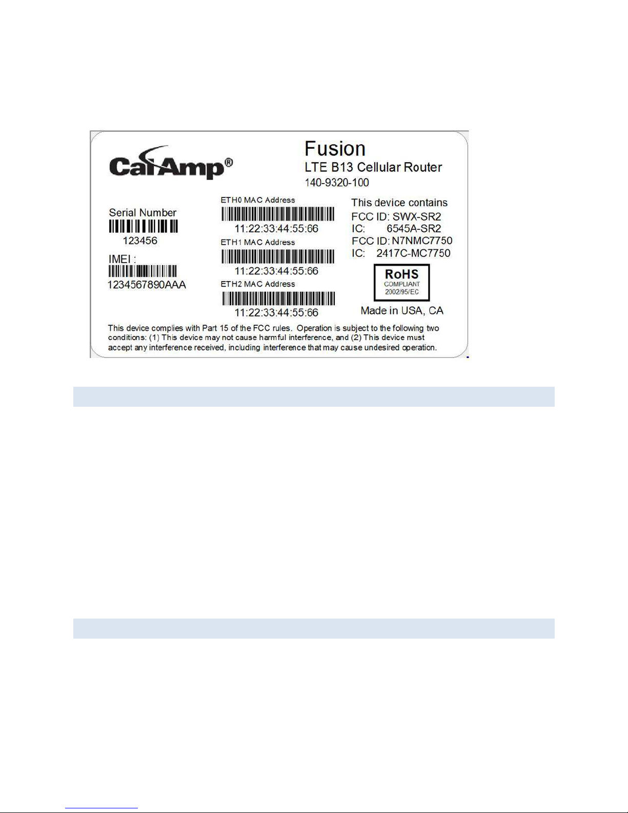
1.2 MODULE IDENTIFI C ATION
The module identification label can be found on the bottom of your Fusion device. This label contains the product part
number, the serial number, FCC and IC IDs as well as carrier specific information that will be required when activating your
data account.
Page 8
8
Figure
1:
Fusion Label Example
1.3 FEATURES AND BENEFITS
• Supports dual cell modules for mixing public and private bands or multiple carriers.
• Band 14 LTE for private infrastructure
• Band 13, 17 or 4 LTE for public infrastructure
• Superior RF performance with MIMO capabilities
• Secure IPSec VPN connectivity
• Autonomous WAAS enabled GPS with local and host reporting
• Supports Dynamic or Static WAN IP
Inbound and Outbound Ethernet Routing
DHCP Server and Inbound port mapping/translation (Port Forwarding)
Firewall configuration for increased network security
Diversity antenna port/auxiliary port for increased receive sensitivity for dual cell module
Local or remote configuration using HTML web server
Inbound IP termination with Static IP
Persistent Domain Names with Dynamic DNS
Internet access and web browsing via Ethernet connector
Dual SIM card slot, support multiple carrier contracts.
1.4 GE N ER AL SP ECIFIC AT IONS
Product specifications
GENERAL
Input Voltage 10 to 30 VDC
Page 9

9
Power Consumption RX: 5.5W Cell and GPS, 7.7W with WiFi
TX: 9.1W Cell and GPS, 13.0W with WiFi
LTE Diversity Support DL MIMO, UL SISO
Security 3GPP Rel 8 security sublayer, IPsec VPN
Certifications FCC Part 15 Subpart B Class A, IC ICES-003, Carrier Approvals (Pending)
CONNECTORS/INTERFACE
Device Management SNMP, embedded HTTP server for setup and help
LED Indicators WWAN0, WWAN1, WiFi, GPS, POWER, ETH0, ETH1, ETH2, STATUS
Power 4-pin locking, ignition sense and alarm inputs
Console/Setup 3-wire serial connection in USB MiniB form factor
Ethernet (3) 10/100 Mbps RJ-45, auto MDIX, Auto negotiation
USB (2) Type A female
I/O 2 digital I/O, 2 analog inputs,
2 outputs (relay driven contact closures)
Antenna (3) SMA-RP (802.11 b/g or b/g/n WiFi)
(2) SMA (cellular) WWAN0
(2) SMA (cellular) WWAN1
(1) SMA (GPS)
MECHANICAL/ENVIRONMENTAL
Dimensions 5.5 (L) x 6.0(W) x 1.8(H) in, 14x15.25x4.5 cm
Weight 2.5 lb, 1.13 kg
Temperature Range -30° to +60° C, -22° to +140° F
Humidity 5% to 95% non-condensing
LTE TECHNOLOGY/BANDS
Band 14 700 MHz “D” Block DL MIMO, UL SISO
Band 13 700 MHz DL MIMO, UL SISO
Page 10

10
Band 17 700 MHz DL MIMO, UL SISO
Band 4 1700/2100 MHz AWS DL MIMO, UL SISO
CDMA TECHNOLOGY/BANDS
EVDO Rev A (IS-856-A) 800 MHz Cellular/1900 MHz PCS
Downlink 3.1 Mbps; Uplink 1.8 Mbps
1xEVDO Rev 0 (IS-856) 800 MHz Cellular/1900 MHz PCS
Downlink 2.4 Mbps; Uplink 153.6 kbps
1xRTT (IS-2000) 800 MHz Cellular/1900 MHz PCS
Downlink 153.6 kbps; Uplink 153.6 kbps
GSM TECHNOLOGY/BANDS
UMTS/HSPA Quad-band 850/9001900/2100 MHz
Downlink 7.2 Mbps, Uplink 2.0 Mbps
EDGE/GPRS Quad-band 850/900/1800/1900 MHz
Downlink 236 kbps, Uplink 236 kbps
WIFI TECHNOLOGY/BANDS
IEEE 802.11 b/g or b/g/n 32 bit mPCI type lllA high power/performance WiFi
Security WPA-PSK (TKIP encryption), WPA2-PSK (CCMP encryption), 64-bit/128 bit WEP
encryption
Data Rates 802.11b: up to 11Mbps
802.11g: up to 54Mbps
802.11n: up to 300Mbps
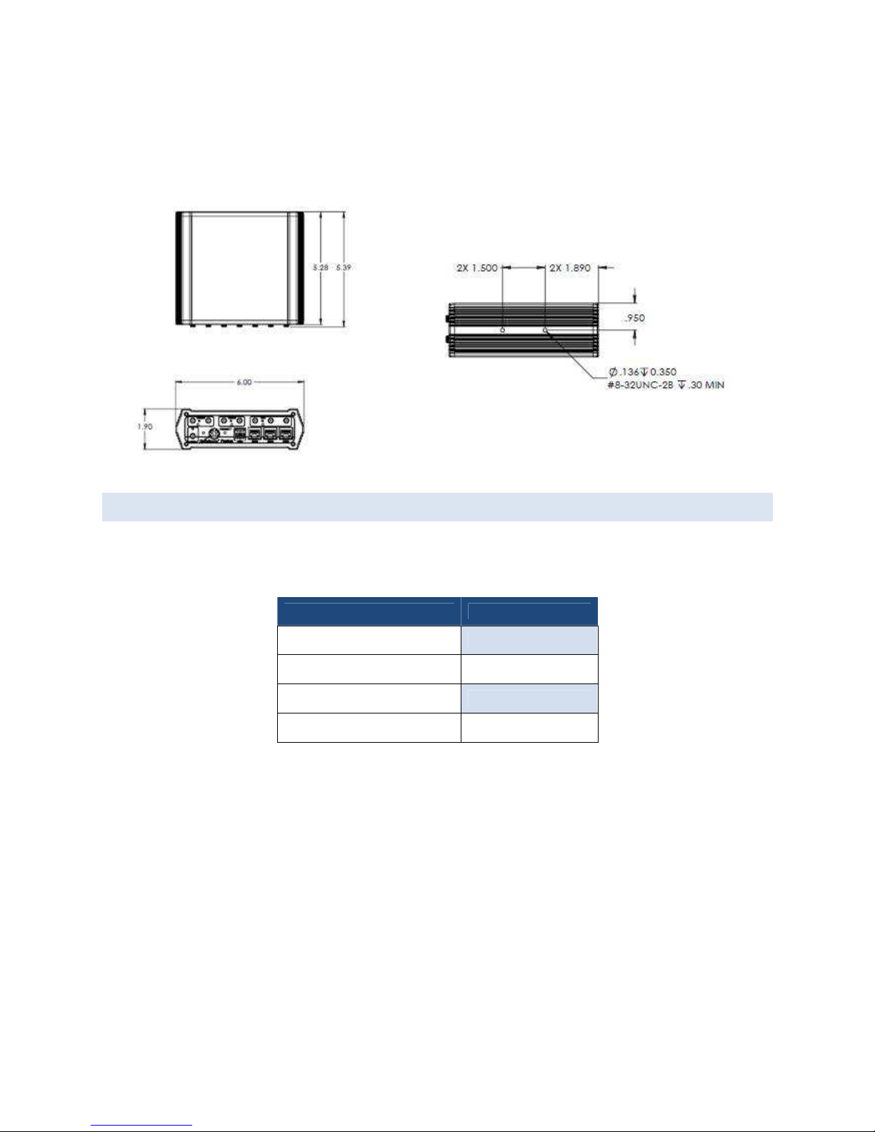
The following section describes in detail the exterior dimensions of the Fusion modems and how to utilize the mounting
flanges to secure the modem to any surface, which can be drilled for such a purpose. The drawings may be used as layout
reference, but it is advised that a physical comparison be made to the modem before proceeding with the mounting
process.
Page 11
11
Figure 2: Fusion LTE Mechanical Drawing
1.5 ORD ER INFORMAITON
Table 1 shows the available order options and the part numbers required for ordering Fusion modems.
Table 1 - Fusion LTE Order Information
DESCRIPTION MODELS
BAND 13 FIXED 140-9320-000
BAND 13 MOBILE WITH WIFI 140-9320-100
BAND 17 FIXED 140-9340-000
BAND 17 MOBILE WITH WIFI 140-9340-100
Page 12

12
CA Part Number
Description
Comments
4019300001
ANTENNA, LTE LPROFILE HGAIN (BAND 13/BAND17), MAG MOUNT, W GND
PLANE DISC, SMA 15FT, 3G FALLBACK Standard Demo Antenna
4019300101
ANTENNA, LTE LPROFILE HGAIN (BAND 13/BAND17), THREAD MOUNT, SMA
15FT, 3G FALLBACK, WHITE
4019300102
ANTENNA, LTE LPROFILE HGAIN (BAND 13/BAND17), THREAD MOUNT, SMA
15FT, 3G FALLBACK, BLACK
4019300201
ANTENNA, LTE LPROFILE HGAIN (BAND 14), THREAD MOUNT, SMA 15FT, 3G
FALLBACK, WHITE
4019300202
ANTENNA, LTE LPROFILE HGAIN (BAND 14), THREAD MOUNT, SMA 15FT, 3G
FALLBACK, BLACK
4017100003 ANTENNA, GPS, SMA, MAG MOUNT, SMA
4017100004 ANTENNA, WIFI, 9" MAG MOUNT, RP-SMA
4977001200 CAT5E STP 25FT SHIELDED PATCH CABLE WITH RJ45 CONNECTORS (350-MHZ)
8179300901 FUSION MOBILE MOUNTING BRACKET Included with Mobile Models
4759808006 SLOTTED SHOULDER SCREWS FOR MOBILE MOUTING BRACKET (NEED QTY 4) Included with Mobile Models
8179300902
FUSION FIXED MOUNT, MOUNTING BRACKET
Included with Fixed Models
4751206308 FUSION FIXED MOUNT, MOUNTING SCREWS (NEED QTY 4) Included with Fixed Models
Table 2 - Fusion LTE Accessories
1.6 EXTERNAL CONNECTORS
This section describes the external connectors for the Fusion LTE modem.
Page 13
13
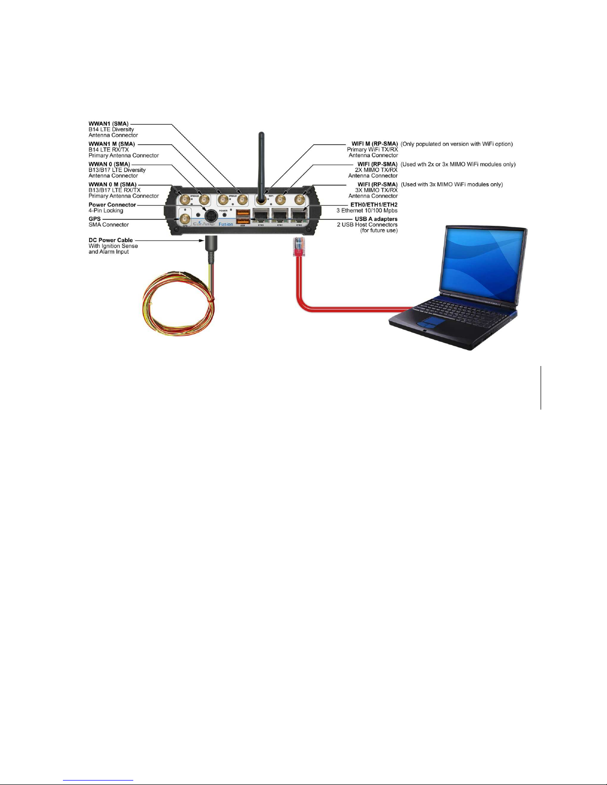
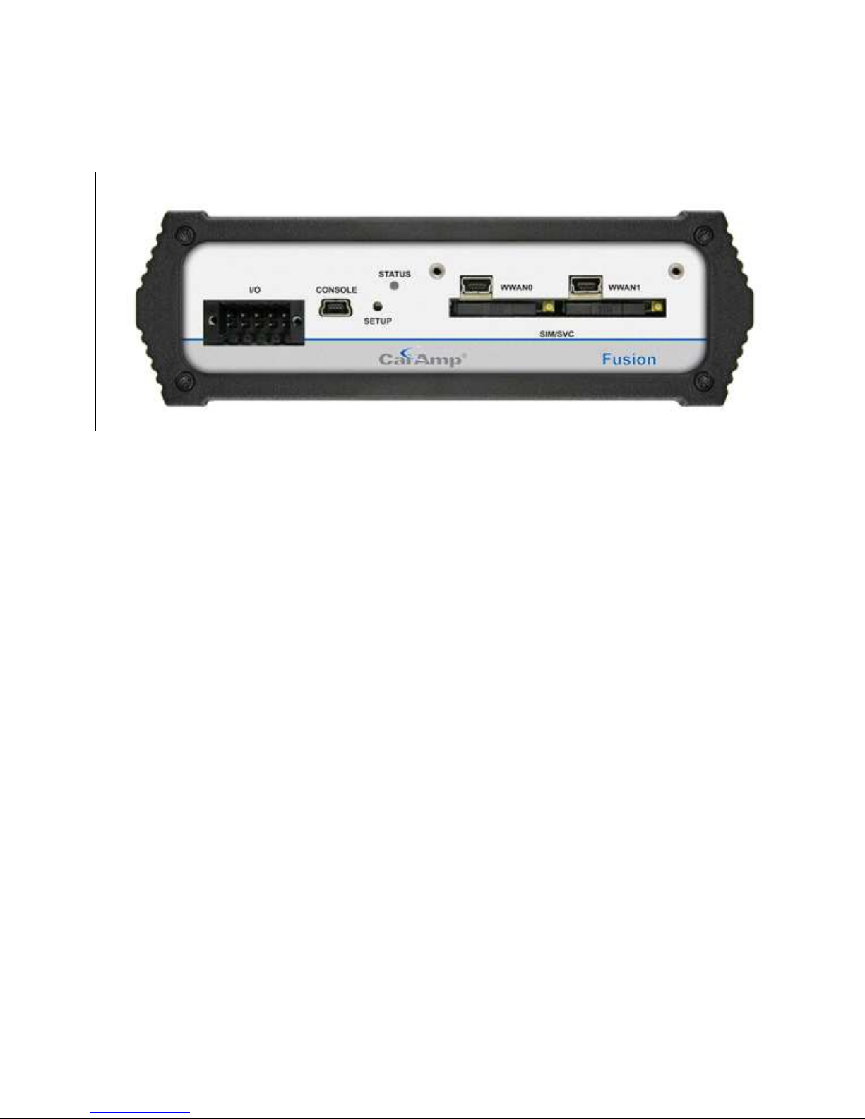
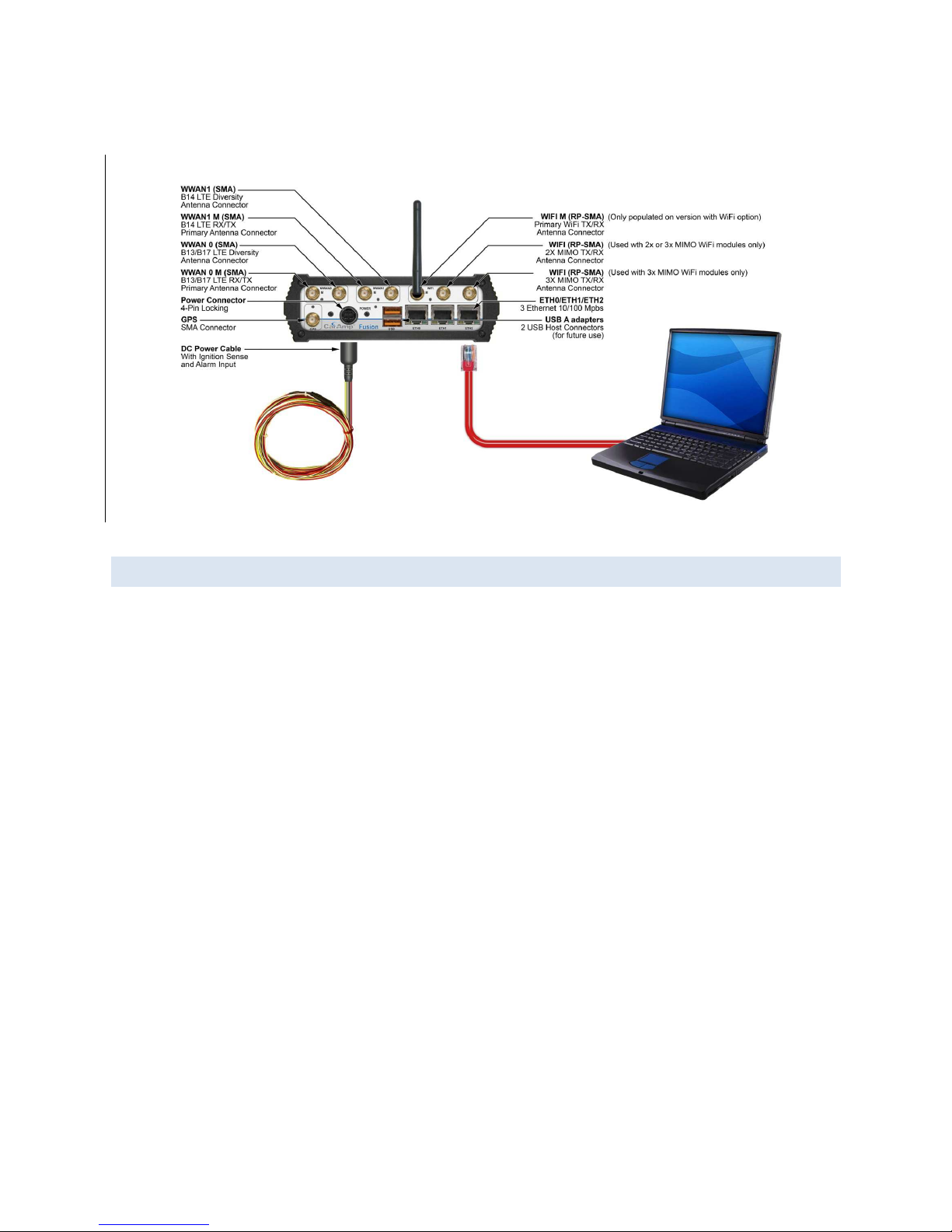
Figure 3: Front Panel
First Row, from left to right:
WWAN0 M : B13/B17 LTE RX/TX primary antenna connector (SMA)
WWAN0: : B13/B17 LTE diversity connector (SMA)
WWAN1 M : B14 LTE RX/TX primary antenna connector (SMA)
WWAN1: B14 LTE diversity connector (SMA)
WIFI M: Primary WiFi TX/RX antenna connector, RP-SMA. (Only populated on version with WiFi option)
WIFI (center connector): 2X MIMO TX/RX antenna connector, RP-SMA (Used with 2x or 3x MIMO WiFi modules only)
WIFI(farthest to the right): 3X MIMO TX/RX antenna connector, RP-SMA (Used with 3x MIMO WiFi modules only)
Second Row, from left to right:
GPS: GPS Receive antenna (SMA)
Power: 4 pin locking power, ignition sense and alarm input.
USB A adapters: 2 USB Host connectors (for future use)
ETH0/ETH1/ETH2: Three Ethernet 10/100 Mbps RJ45 connectors
Page 14
14
Figure 4: Rear Panel Connections
Back panel connectors Left to Right:
I/O: I/O 2 digital inputs / outputs, 2 analog inputs, 2 outputs (relay driven)
Console: USB Device port, used for debug only.
Setup: Pushbutton Reset / Force Factory Settings
Status: Bicolor Status LED
SIM / SVC (left): SIM card slot for module in WAN slot 0
WWAN0: Mini USB Service Port, Direct connection to WWAN0 module, used to change firmware or configure the cellular
modem
SIM / SVC (right): SIM card slot for module in WAN slot 1
WWAN1: Same as WWAN0 except for the module in slot 1
Page 15

15
1.7 LEDS
Table 3 - Status LEDs
INDICATOR
OFF SOLID
GREEN
FLASHING
GREEN
SOLID
AMBER
FLASHING
AMBER
SOLID
RED
FLASHING
RED
PWR
No Power Running -
Hardware
Power up
sequence
Firmware
boot
sequence
Power-Down
Timer
Activated
(1)
Power
Supply Fault
STAT
No Power
Status
NORMAL
-
Status
WARNING
Status
FACTORY
DEFAULTS
Status
FAULT
GPS
-
Position Fix
Acquired
1 PPS
activity
Failed to
Acquire
Satellites
Acquiring
Satellites
FAULT
WiFi
(2)
(Client)
I/F Disabled Connected
RX/TX
Activity
Failed to
Connect
Connecting FAULT
WiFI
(2)
(AP)
I/F Disabled READY
RX/TX
Activity
- - FAULT
WWAN0/1
I/F Disabled Connected
RX/TX
Activity
Failed to
Connect
Connecting FAULT
ETH
LINK/ACT
No link Link Ok Activity - - -
ETH
SPEED
10Mbsp - - 100Mbps - -
(1) The “Power-Down Timer Activated” is a transient condition that exist when the “ignition” input is OFF and the
“power management – shutdown when ignition is off” feature is activated. It means that the unit is about to
shutdown and this will occur when the timer has expired.
(2) WIFI Client has priority over the WIFI AP function. This implies that WIFI Client has ownership of the LED when it is
enabled. WIFI AP has ownership of the LED only if the WIFI Client if disabled.
Page 16

16
Normal power-up sequence
The LEDs will act differently during boot up than during normal operation.
Step Action LED activity
1 Apply power to the unit. NA
2 Internal 5-volts power supply turns-on PWR = RED during approx 1 second
3 Internal 1.8-volt and 3.3-volts power supply turn-on Every INDICATOR (except those attached to Ethernet)
become AMBER during approx 400 ms
4 Hardware initialization completed
Every INDICATOR become OFF except PWR which remain
AMBER.
5 Bootstrap program runs
PWR blinks AMBER.
6 Application starts
PWR becomes solid GREEN.
7 Application runs normally
PWR is solid GREEN. STAT is solid GREEN
1.8 ANTENNA
LTE antenna connections are SMA female connectors and must be used with antenna with SMA male connectors. When
using a direct mount or rubber duck antenna, choose the antenna specific to your band requirements. Mounting options
and cable lengths are user’s choice and application specific. Each WWAN interface supports a primary and diversity antenna
connector.
Connect an active 3-5.5V GPS antenna, with an average gain >-5dBi, if using the GPS functionality.
Fusion is available with WiFi options, using RP-SMA connectors. Depending on the model, connect each WiFi antenna to the
proper connector. If equipped with a simple non-MIMO WiFi option, connect the primary WiFi antenna to the connector
labeled “M’. For Fusions equipped with MIMO WiFi (2x2 or 3x3 MIMO), connect the WiFi antennas to any free RP-SMA
connector.
This device is factory configured with default settings and is ready to be customized via HTML.
Page 17

17
2 G E T T I N G S T A RT E D
2.1 PACKAGE CONTENTS
Fusion LTE Modem
Power Cable
Mounting Bracket and hardware (Fixed or Mobile depending on device purchased)
Quick Start Guide
2.2 POWER SUPPLY CONN ECTION
The fusion is shipped with a DC power cable used to connect the device to a DC source. The cable includes a fuse holder.
Insert the fuse in the power cable fuse holder prior to powering on the unit. The cable connections are listed below.
Pin Wire Color
Descriptio
n Notes
1 Red V IN DC input power lead, 13.8V nominal (10V to 30V range)
2 Black Ground
Connect to power supply ground
3 White
Ignition Sense
Standard ignition
-
on signal.
Maximum voltage above which Ignition_sense
will be detected as ignition asserted = 9.0V;
If IGN Sense not used, this line must be connected to VIN
4 Yellow
External Alarm Input
External alarm input,
(active low)
can be left floating if not used
2.3 DEVICE CONNECTIONS
1. Insert the SIM/UICC card into the SIM/SVC slot as shown. If your solution requires only one cellular module, insert
the SIM into the slot corresponding to the populated module (WWAN0 (left), WWAN1 (right). If you are using a
dual card solution, you will need a SIM card in each slot.
2. Connect the antennas to the appropriate connectors on the front panel of the Fusion LTE modem.
3. Connect an Ethernet cable into the Eth1 port and plug the other end into the network port of your PC.
4. Connect the Power Cable to the modem PWR port and connect to an acceptable DC power source (10-30VDC).
Page 18
18
2.4 LAN CONFIGURATION
The Fusion contains a DHCP server which will automatically assign an IP address to your PC, however in some cases the user
may need to change the network settings on their PC to accept the IP address from the Fusion. Before powering on the
unit, confirm that your PCs Ethernet port is set up to receive an IP address from an external DHCP server, confirm it is not
set to a static address. The process to do this differs depending on the version of Windows you are using.
Page 19
19
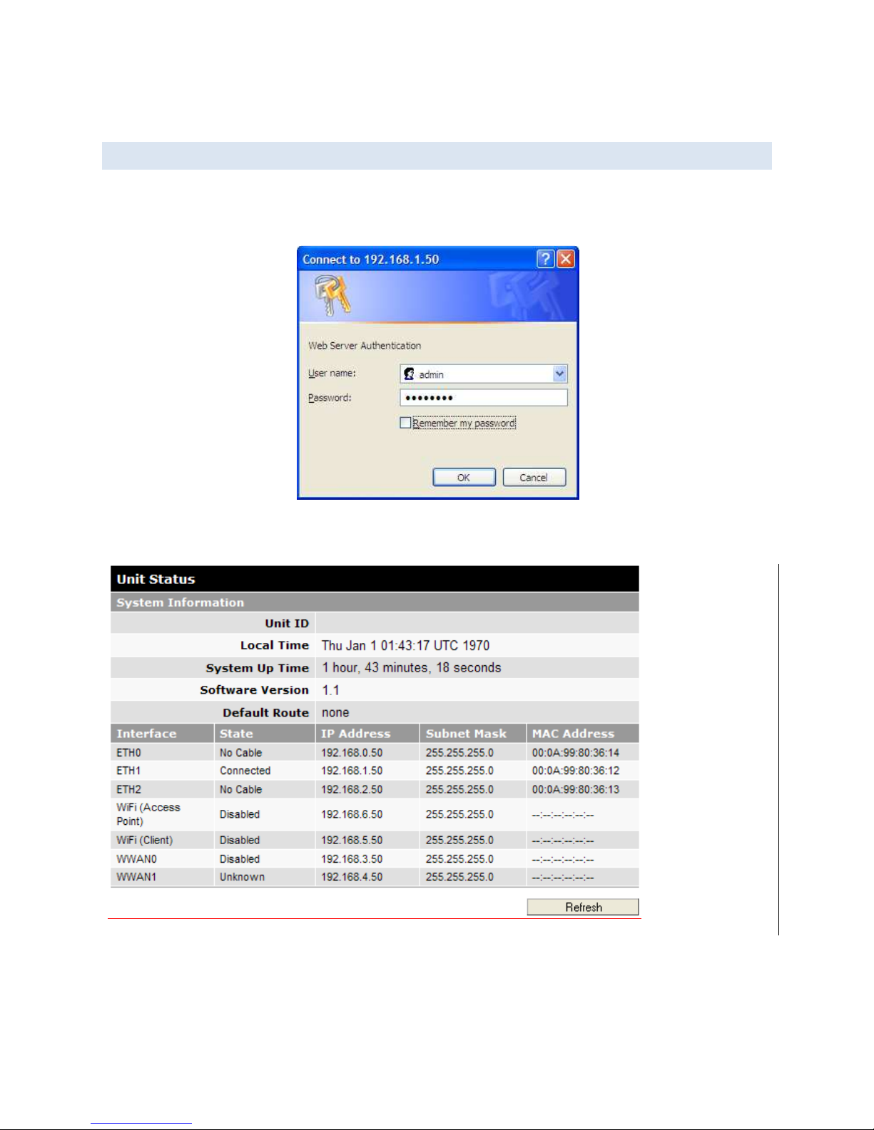
2.5 LOG IN
Start your web browser and enter 192.168.1.50 in the address bar. A login screen should appear
Note: The Ethernet cable between the Fusion and your PC must be connected to ETH1, for this IP address to work.
Enter the User Name: admin and the Password: password and click OK to log into the modem’s Home Page. This will bring
up the unit status page.
Page 20
20
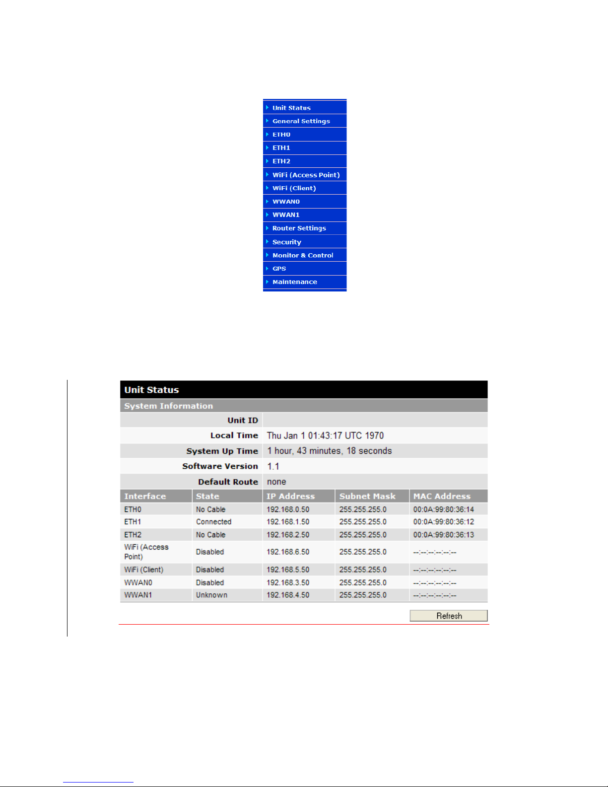
The Fusion LTE Web interface is divided into two sections. On the left is the main navigation panel (shown in Figure 9). On
the right is the content area for the desired page.
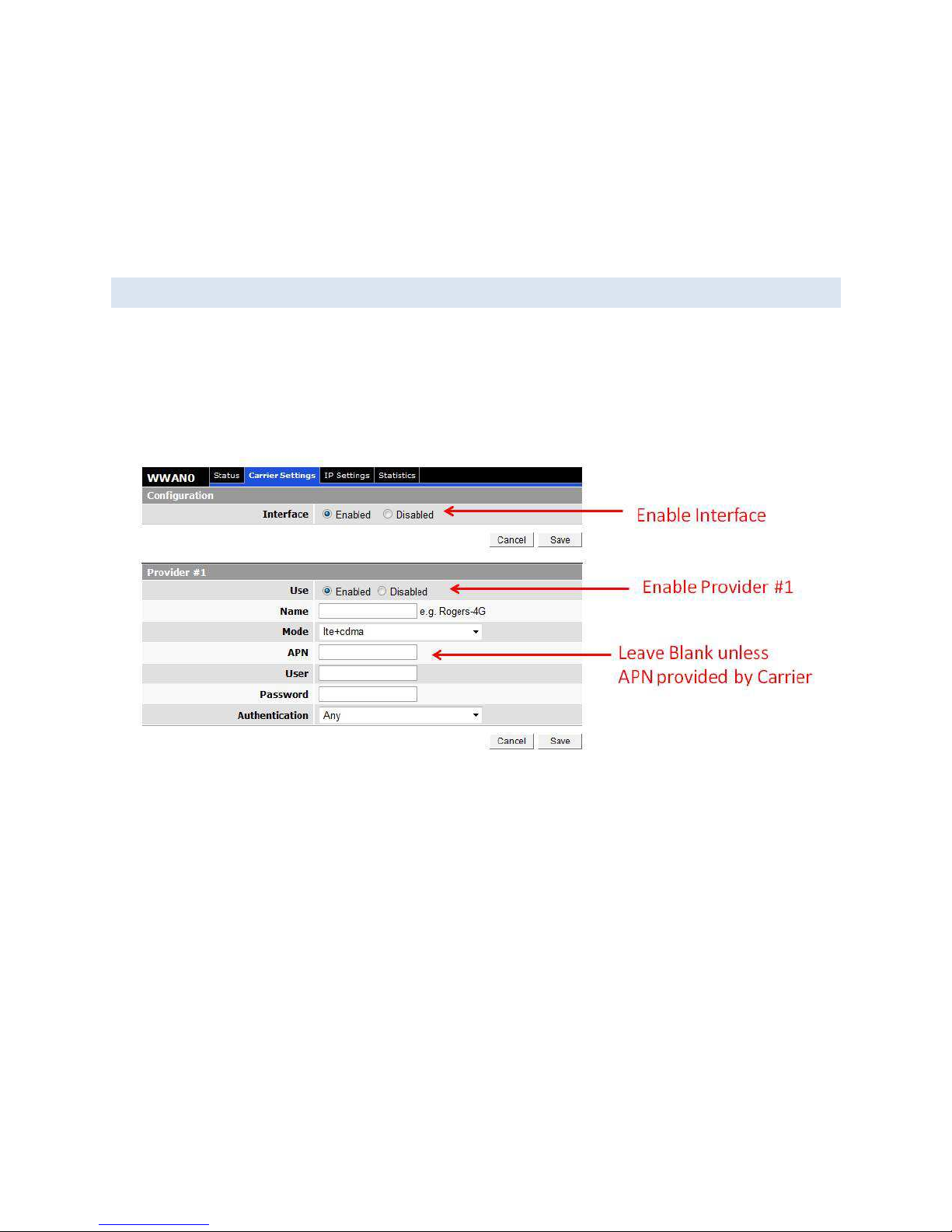
2.6 LTE CONNE CTION
Before you begin this step, you will need an LTE contract with a carrier and an active SIM card.
On the left side of the screen, select WWAN0. This will bring up the WWAN0 status page. Select the Carrier Settings tab.
On the Carrier Settings page, enable the Interface and Provider #1 (If not done by default). You will have to hit save after
each change.
The APN, User and Password should be left blank unless you have received specific values from the Carrier. In most cases,
Authentication should be left as Any.
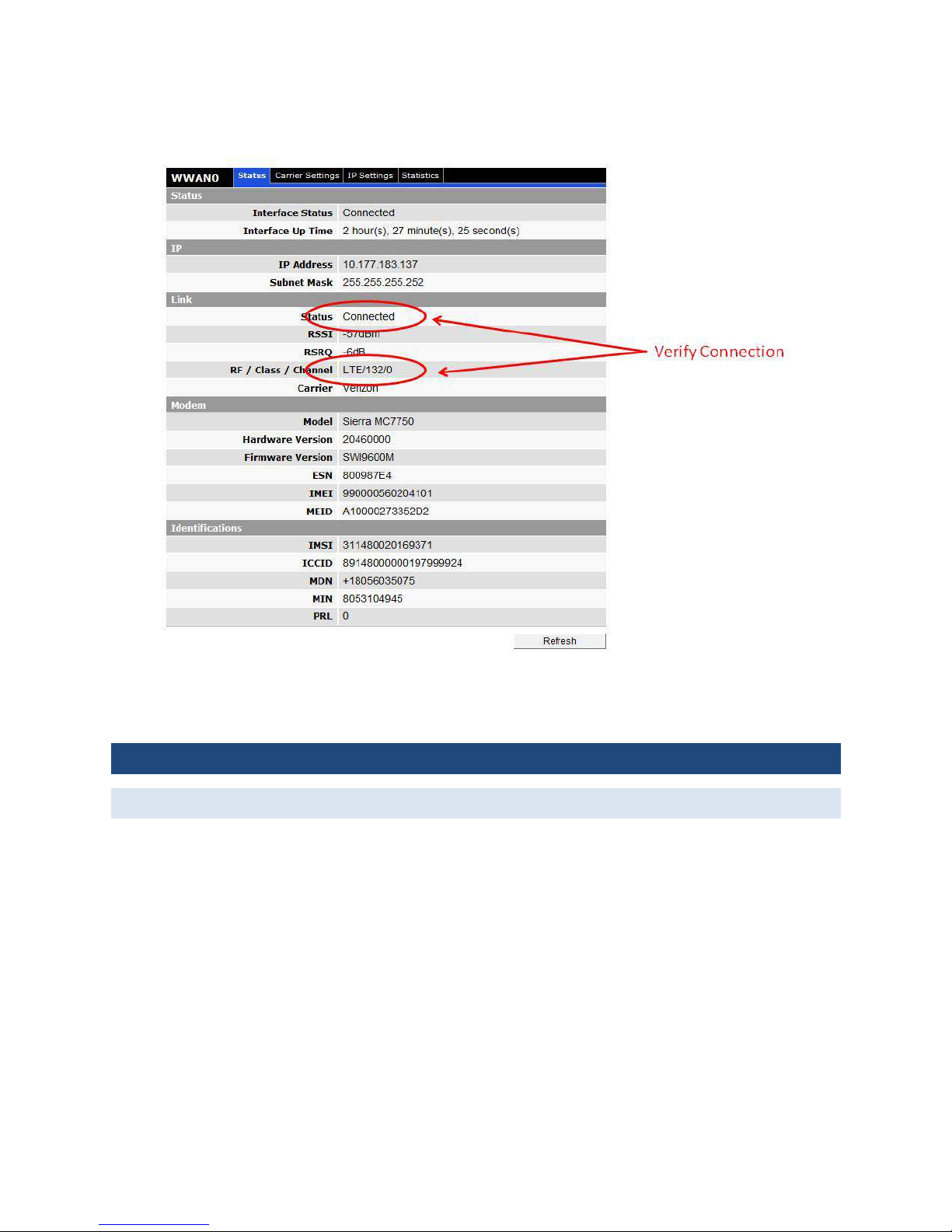
It may take several minutes to establish the connection after it has been enabled for the first time. Verify the connection is
active by click on the Status tab. See below.
Page 21
21
3 W E B I N TE RF A C E
3.1 UNIT ST ATUS
Select Unit Status window is the first window the user will see when logging into the unit. A description of the parameters
listed on this screen is provided below.
Page 22
22
Figure 10: Main Navigation Panel
On the left side of the home page is the navigation panel shown above. The options on your unit may vary from the
example depending on the options installed on your unit.
Figure 5: Fusion LTE Unit Status Window
The unit status page gives an overview of the status of the unit.
Page 23

23
System Information
Unit ID
User-defined for ease of reference, used by various services
Time
Displays the current date and time (UTC) as received from the GPS receiver.
System Up time
Displays the system uptime in hours, minutes, seconds
Firmware Version
Displays the current modem firmware version loaded. Please visit www.calamp.com for the latest updates.
Default Route
Displays the name of the WAN interface used as the default route. This value can change dynamically based on the
available WANs and WAN failover rules specified.
Interface Information
Interface
Name of the interface
State
Displays the current state of the interface. The possible states are listed below
ETH (LAN)
ETH (WAN)
WIFI-AP WIFI-CLIENT
WWANx
Unknown
Unknown
Unknown
Unknown
Unknown
Disabled
Disabled
Disabled
Disabled
Disabled
Inactive
Inactive
Inactive
Inactive
Disconnected
No Cable
No Cable
Configuring IP
Scanning
Connecting
Configuring IP
Acquiring IP
Connect
ing Acquiring IP
Connected
Connecting
Connecting
Connected
Connecting
Connected
Connected
Connected
IP
Displays the IP address of this interface
Subnet Mask
Displays the subnet mask of this interface
MAC Address
Page 24
24
Media Access Control Address; every interface (i.e. LAN or WAN) has a unique hardware serial number or MAC
address to identify each Network Device from all others. Note that the optional WiFi client and Access Point
interfaces are provided by the same hardware module and therefore share the same MAC address.
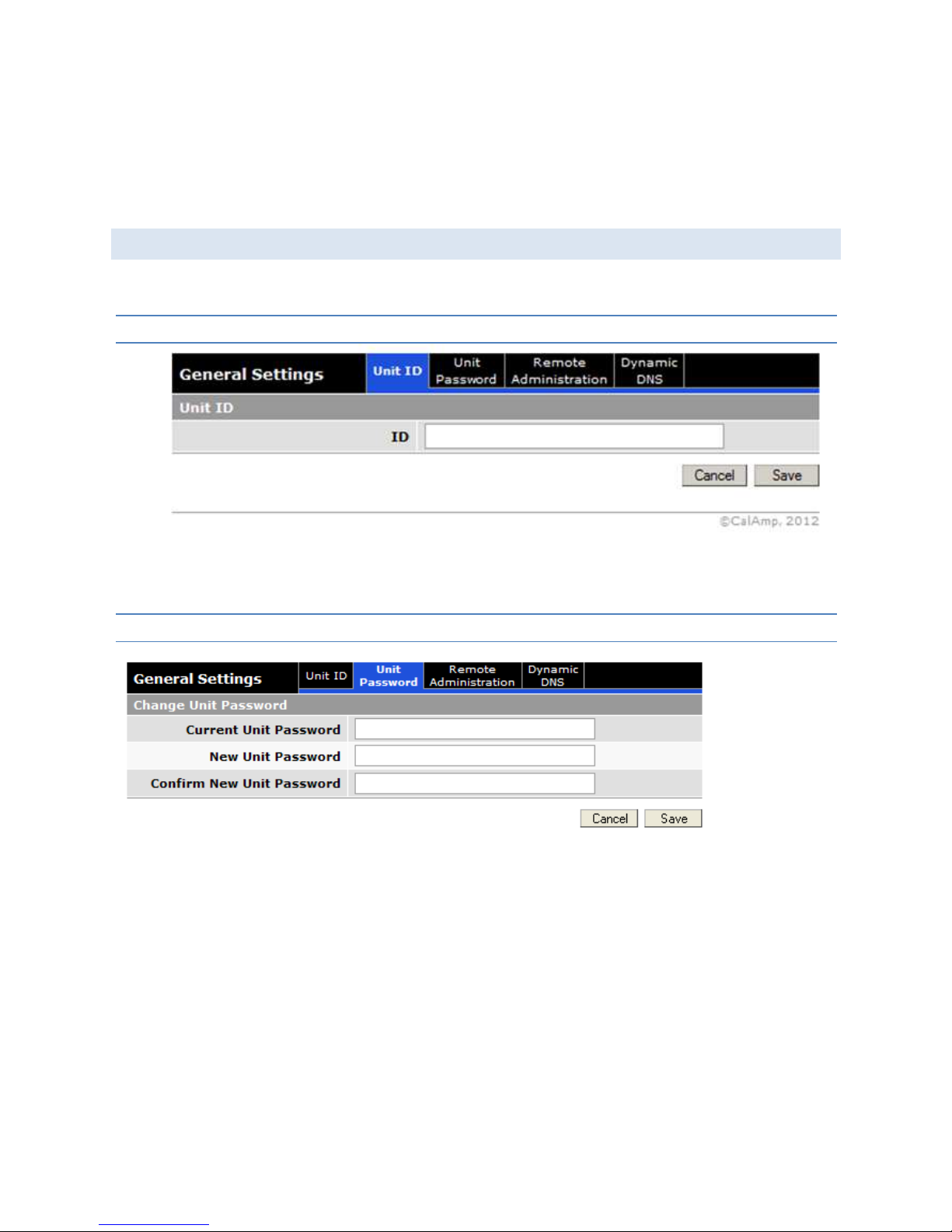
3.2 GE N ER AL SETTING S
The General Settings tab allows the user to customize the basic settings of the device.
3.2. 1 UNIT ID
ID
The identification number serves to distinguish this unit. It is at the same time the TAIP identification for GPS
reporting.
3.2. 2 UNIT PASSWORD
• Current Unit Password
The current unit password must be provided here to enable changing it
• New Unit Password
Enter new password here
• Confirm New Unit Password
Re-enter new password
This password controls access to the unit HTML configure pages via a local Ethernet connection and via Remote Login (See
Remote Administration section). Some functions such as SNMP will require and additional password.
Page 25

25
3.2. 3 REMOTE ADMINISTRATION
Allows remote (over-the-air) configuration of the Fusion via HTTP, SNMP and Telnet. To connect remotely to the services
listed on this page, enter the WWAN IP of the device in a browser followed by the port set here. Example
172.193.50.1:80
For each service type, Selecting Enabled will allow remote access to the modem’s configuration over-the-air.
Selecting Disabled will shut off the ability to remotely access the modem’s configuration.
Port
Specifies the IP port to use for each service.
3.2. 4 DYNAMIC DNS
Page 26

26
Dynamic DNS is a system which allows the domain name data of a computer with a varying (dynamic) IP addresses held in a
name server to be updated in real time in order to make it possible to establish connections to that machine without the
need to track the actual IP address themselves at all times. A number of providers offer Dynamic DNS services ("DDNS"),
free or for a charge.
Fusion allows distinct IP address / mnemonic name association for each of its WAN interfaces, as well as for the WAN
interface used as the default route. En example use would be: car54 (for the default route), car54_wifi, car54_LTEB14,
car54_VZW.
Configuration
Dynamic DNS
Selecting Enabled will allow the modem to provide the selected service dynamic IP address information. Selecting
Disabled will stop any IP information from being sent to the selected service.
Client
Select the Dynamic DNS client to use. No-IP is the default DNS service.
Server Settings
Dynamic DNS Address
The internet address to communicate the Dynamic DNS information to. Default is dynupdate.no-ip.com.
User Account
The username used when setting up the account, used to login to the Dynamic DNS service.
User Password
The password associated with the username account.
Update Interval
Sets the interval, in minutes (0 to 65,535), the modem will update the Dynamic DNS server of its carrier assigned IP
address. Each update is considered a data call by the cellular provider and could deplete low usage data plan
minutes. Setting the duration too long could lead to periods of lost connectivity when the device IP address
changes.
Client Settings
Enable
The IP address updates will only be supplied to the service if this radio button is set.
Host Configuration
The mnemonic name to register with the DDNS service
WAN Interface
The WAN interface whose IP address will be published for this DDNS registration.
The CLEAR button on each entry can be used to remove that particular DDNS configuration.
Page 27

27
The SAVE button must be pressed for changes to take effect.
3.3 ETHERN ET 0 / 1 / 2
The same settings apply to all Ethernet interfaces. Each Ethernet interface can be configured as a LAN or a generic WAN.
3.3. 1 STATUS
ETH configured as a LAN
ETH configured as WAN
Page 28

28
Status
Interface Status:
See unit status section for a list of potential states.
Interface Up Time:
Number of Days, Hours, Minutes, Seconds the interface has been up (connected state)
IP
IP address
IP address assigned to this interface
Subnet Mask
Subnet Mask assigned to this interface
The following only apply when the interface is configured as a WAN
Gateway
IP address of the WAN gateway
DNS Server
IP address of the preferred and alternate DNS server
Lease Time
If the interface is setup to request an IP address from a DHCP server, this is the lease duration.
Page 29

29
Lease Expires In
If the interface is setup to request an IP address from a DHCP server, this is the time remaining in the current lease.
Link
Cable Status
Connected or Disconnected
3.3. 2 IP SETTINGS
Ethernet configured as a LAN
Modes of Operation
Page 30

30
Select LAN if this Ethernet port is connecting to a local area network. Select WAN if the Fusion is connecting to a
wide area network through an external router or gateway
IP Configuration
• IP Address/Subnet Mask:
Same as in previous section
• MTU:
Maximum Transmission Unit, max packet size allowed to be transmitted, should be left as default in most cases.
DHCP Server Configuration
• DHCP Server:
When enabled, the DHCP server will assign IP address to a device or devices connected to the Ethernet port. IP
addresses assigned will be in the defined range (see below) and on the same subnet as the Fusion.
• Dynamic Leases (Start IP Address/End IP Address):
External LAN devices connected to the Fusion will be assigned IP address in this range when DHCP is enabled. This
range of IP addresses must be on the same subnet as Fusion.
ETH Configured as a WAN
IP Configuration
• Mode
Page 31

31
Select Dynamic or Static. If you select Dynamic the rest of the entries on this page will be shaded out.
• IP Address
Static address for this interface, must be on the same subnet as the gateway.
• Subnet Mask
This will be assigned by the gateway.
• Gateway
IP address of the Gateway (DHCP host), if not known this can be left as all 0s.
• DNS Server x
IP address of the DNS server for this unit. If not known, this can be left all 0s.
NAT Configuration
Enable or Disable NAT
3.3. 3 STATISTICS
The statistics page lists the total number of packets and bytes transmitted and received since the time the units status
was listed as connected. These numbers reset to 0 when the Ethernet interface disconnects.
3.4 GE MI NIG3 (E TH2)
This menu selection replaces the ETH2 LAN setting on Fusions equipped with the narrowband WAN option.
When equipped, this option transforms the ETH2 LAN into a Narrowband WWAN interface by customizing the ETH2
configuration screen to the CalAmp Gemini product line.
Refer to CalAmp part number 001-0001-401 “GEMINI G3 ADB USER MANUAL” for details on the GeminiG3 configuration
Page 32

32
The Gateway and Subnet mask will be assigned by the GeminiG3 in this configuration.
3.5 WI FI ( ACCESS POI NT)
3.5. 1 STATUS
Interface Status: See Unit Status Screen
Interface up time: Same as previous section
Page 33

33
IP Address: Same as previous section
WiFi Status: When status is listed as N/A, the interface is disabled; when status is listed as Ready: Interface is ready to
accept clients.
3.5. 2 WIRELESS SETTINGS
• Interface: Enabled or Disabled
• SSID: The SSID is the name of the wireless local network. All devices connecting to the Fusion WiFi access point
must have the same SSID. Check the “hide” box to prevent the WiFi Access Point from transmitting the SSID. This
will improve the security of the device.
• Channel: Select the WiFi channel the module will transmit on. If there are other WiFi devices in the area the
Fusion should be set to a different channel than the other access points.
• Authentication: Select authentication method, options are Shared; WPA-PSK and WPA-PSK2. WPA-PSK2 is the
recommended setting if security is required.
• Encryption: Select encryption method, options are None, WEP, TKIP, or CCMP. Depending on the authentication
method selected, some options will not be available here.
• WEP Key Length: Choose 64 or 128 bit key. This is only available if the WEP option is selected for encryption.
3.5. 3 IP SETTINGS
Page 34

34
All definitions on this page are the same as defined in the ETHx configuration settings.
3.5. 4 STATISTICS
Parameters in this section have the same definitions as the ETHx configuration settings.
3.6 WI FI ( CLIEN T )
Page 35

35
3.6. 1 STATUS
See Table in Unit Status Section
3.6. 2 IP
Interface Up Time: Same as defined in ETHx sections
Lease Time: Amount of time the IP address assigned by the host is valid for.
Lease Expires In: When the current assigned IP address will expire and a new IP will be required from the host
All other parameters the same as defined in the ETHx sections.
3.6. 3 LINK
Wi-Fi Status: See table in Unit Status Section
BSSID: BSSID refers to the MAC address of the Station (STA) in an Access Point (AP) in an infrastructure mode BSS defined
by the IEEE 802.11-1999 standard.
SSID: An SSID is the public name of a wireless network. All of the wireless devices on a WLAN must employ the same SSID
in order to communicate with each other.
Page 36

36
Authentication: Security mode as set by the WiFi access point (WPA, WPA2, etc.)
Encryption: Data encryption method as set by the WiFi access point
Channel: Transmit and Receive channel, defined by the 802.11 specification. This is set by the access point.
Signal Quality: RF quality indicator
RSSI: Receive signal strength indicator
Noise Level: Measurement of the ambient noise in the frequency channel selected
Bit Rate: Over the air throughput measurement, this will be affected by the type of access point connected to (b,g,or n)
and the number of WiFi antennas (1-3) installed on the Fusion.
3.6. 4 WIRELESS SETTINGS
This screen allows the user to setup access points that the WiFi client will connect to automatically. The parameters
entered on this screen are the same as the WiFi access point section, except when operating in the client mode, the
parameters must match what is entered on the access point for the WiFi client to connect successfully.
When entered, the access point will be listed in the access point table at the bottom of the screen.
3.6. 5 IP SETTINGS
Page 37

37
Parameters on this page are the same as defined in the ETHx sections of the document. Other than the mode, MTU and
NAT Enable/Disable; these parameters will be assigned by the WiFi host.
3.6. 6 SITE SURVEY
The site survey scans available WiFi networks and returns the BSSID,SSID, WiFI Channel, Authentication, Encryption and
Signal Quality of available WiFi network.
Note: A site Survey is performed once every time the “Site Survey” tab is accessed.
Page 38

38
Warning: Performing a site survey takes the WiFi radio out of its current channel of operation and will therefore disrupt
any ongoing active Access Point and Client session and may result in data loss.
3.6. 7 STATISTICS
Same as defined in ETHx section.
3.7 WWAN 0 / 1
As a true multi-bearer router, Fusion can be equipped with two distinct LTE modules, each capable of being operational at
the same time.
3.7. 1 STATUS
Page 39

39
Status
Interface Status
See table on unit status page
Interface Up Time
Time that the WAN interface has been up
IP
IP address
WWAN IP address of the Fusion, this will be assigned by the carrier.
Page 40

40
Subnet Mask
Subnet Mask as assigned by the carrier. This value will be dictated by the IP address assigned.
Link
Status
See table in unit status screen
RSSI
Signal strength of the carrier network.
RSRQ
Reference Signal Received Quality.
RF/Class/Channel
Channel or band the WWAN is currently assigned to by the carrier.
Carrier
Wireless network provider
Modem
Model
Model of the cellular module for this WWAN
Hardware Version
Hardware version of the modem: Note this is different than the hardware version of the Fusion itself.
Firmware Version
Firmware version of the modem: Note this is different than the firmware version of the Fusion itself.
ESN
Serial number of the modem; depending on the carrier and technology used, this may be required for the carrier when
activating the data contract. In some cases this will not be populated.
IMEI
International Mobile Electronic Identifier Depending on the carrier and technology used, this may be required for the
carrier when activating the data contract. In some cases this will not be populated.
MEID
Mobile Electronic Identifier: Depending on the carrier and technology used, this may be required for the carrier when
activating the data contract. In some cases this will not be populated.
Page 41

41
Identifications
IMSI
Identification number for the SIM card, (if one is inserted). If no SIM is included this will be blank.
ICCID
Unique mobile serial number assigned to the SIM card
MDN
Mobile Directory Number, this is essentially the phone number for the device assigned when a carrier data contract is
linked with this device.
MIN
Mobile Identification Number, unique identifier used to identify the device within the carrier network.
PRL
Preferred Roaming List, a list maintained by the carrier that outlines when the mobile is in its home network and when
it is in a roaming network. This file will be updated periodically automatically. The PRL file number may be requested
during a technical support call.
3.7. 2 CARRIER SETTINGS
For each WWAN interface, up to 4 LTE providers can be specified. Fusion will try to connect to each in succession when the
interface is enabled.
Page 42

42
3.7. 3 CONFIGURATION
Interface: Enabled or Disabled
3.7. 4 PROVIDER
Use: Enable or disable this provider
Name: Name assigned by the user to identify this account
Mode: Mode of operation of the cell module. Valid modes are offered based on the LTE module type. Typically LTE only,
LTE with 3G fallback, 3G only. B13 example: LTE, LTE+CDMA, CDMA.
APN: Access Point Name, provided by the carrier
User: User name to specify when trying to establish a connection, carrier-provided
Password: Password to specify when trying to establish a connection, carrier-provided
Authentication: Authentication method used by the carrier: Any, PAP, CHAP
Page 43

43
3.7. 5 IP SETTINGS
Parameter definitions on this page are the same as in the ETHx pages accept the parameters are defined by the WAN
network provider/carrier.
3.7. 6 STATISTICS
Parameter definitions on this page are the same as in the ETHx pages accept the parameters are defined by the WAN
network provider/carrier.
3.8 ROUTER SETTINGS
Page 44

44
3.8. 1 INTERFACE PRIORITY
Fusion allows failover of the default route to WAN interfaces in a specific order. This group of settings allows the user to
rank each WAN interface in order of preferred usage for the default route. The default route will always be set to the
highest priority connected WAN interface. This assignment changes as WAN interfaces connect / disconnect from the
associated bearer network.
3.8. 2 APPLICATION ROUTING
Page 45

45
Fusion allows rule-based application traffic forwarding to specific WAN interfaces. Up to 20 rules can be specified, in each
case specifying where ingress traffic (traffic entering Fusion from a LAN interface) should be forwarded. Up to 3 egress WAN
interfaces can be specified. The traffic meeting the ingress classification rule will be forwarded to the highest priority
connected WAN interface. This allows the user to specify fallback WAN interfaces for different types of traffic.
Ingress classification rules can be specified based on the physical ingress interface, IP protocol and IP port number.
3.8. 3 PORT FORWARDING
Page 46

46
DMZ SUPPORT FOR WWAN
DMZ is a host on the internal network that has all ports exposed, except those ports forwarded otherwise.
DMZ
Radio button selection to Enable/Disable; Select Enable to allow the modem to use DMZ routes using the address
set in the Destination IP Address. Select Disable to shut down the DMZ functionality.
Friendly IP Address
Optionally restricts DMZ access to only the specified IP address. If set to "0.0.0.0", the DMZ is open to all incoming
IP Addresses.
Destination IP Address
The IP address which has all ports exposed, except ports defined in the Port Forwarding configuration.
Add Rule
No
Rule number
Protocol
Sets the data protocol as either tcp, udp, or both
Source IP Address
Page 47

47
Specifies an IP address that is allowed to access the modem or a wildcard IP address of 0.0.0.0 that allows all IP
addresses to access the modem.
Public Port Number Range
Sets the external port number range for incoming requests. (Note: Port Forwarding rules take precedence over the
services specified in General Settings | Remote Administration | HTTP port, SNMP Port or Telnet Port.)
Private IP Address
Sets the Local Area Network Address of the device connected to the modem's LAN interfaces. Inbound requests
will be forwarded to this IP address.
Public Port Number Range
Sets the Local Area Network port number range used when forwarding to the destination IP address.
Once you have completed the entry of the above fields, press the ADD button to save the new entry.
3.8. 4 MAC FILTERING
MAC filtering allows up to ten unique devices MAC addresses access to the network and will block all other MAC addresses.
MAC Filtering
Page 48

48
MAC Filtering
Radio button selection to Enable/Disable MAC filtering
Allowed MAC Address
Enter the MAC address for a device to be allowed on the network.
LAN Interface
Allows the user to specify which ingress interface that MAC address is allowed to use.
Clear
Press to remove the MAC address from the list of allowed addresses.
Press SAVE/CANCEL to implement or cancel changes.
3.8. 5 IP FILTERING
The "IP Filtering" page is used to configure IP filters.
The user can enter up to 20 IP filters. Each IP filter is identified by a unique number (from 1 to 20). An IP packet goes
through the filtering logic when IP filtering is enabled and:
1) An IP packet is received on one of the interface and is destined to the Fusion LTE unit
OR
2) An IP packet is sent by the Fusion LTE unit
OR
3) An IP packet is forwarded by the Fusion LTE unit.
The filtering logic is the following:
if exists(filter[1]) AND match(packet, filter[1]) then apply(action[1])
else if exists(filter[2]) AND match(packet, filter[2]) then apply(action[2])
else if exists(filter[3]) AND match(packet, filter[3]) then apply(action[3])
...
else if exists(filter[20]) AND match(packet, filter[20]) then apply(action[20])
else process packet normally.
Where:
exists(filter[n]) -> The user as defined filter number n.
match(packet, filter[n]) -> The IP packet matches filter number n.
apply(action[n]) -> The action identified in filter number n.
Page 49

49
IP Filters
IP Filtering
Enable : IP filtering is enabled. Any custom IP filters entered by the user will be taken into account when processing
IP packets. The predefined IP filters will also be taken into account.
Disable : IP filtering is disabled.
Predefined IP Filters
• Drop Remote Pings:
Set this to Disabled if you do not want the Fusion to respond to Pings. This can reduce your data usage and
improve security but make debug more difficult.
• Drop Remote IP Fragments:
In some cases large packets sent by the host will be broken up and sent as fragments to the end device. Enable
this if you want to drop those packets. In most cases this should be left disabled to ensure reliable end to end
communication.
• Drop Invalid Packets:
Select enabled to force the Fusion to drop any incoming packets that have been determined to be invalid.
Add Custom IP Filter
Page 50

50
Add Custom IP Filters
No.
Each IP filter is identified by a unique number from 1 to 20.
Source IP Address
Any: Any source IP Address will satisfy this criteria.
A specific Host IP address can also be specified, or a range of IP addresses via a bitmask (the fifth box after the /)
If the Exclude field is checked, it means that in order for the packet to match with these criteria, it must NOT have
this source IP address (or NOT be in the given source IP address range).
Destination IP Address
Any : Any destination IP Address will satisfy these criteria.
A specific IP address can also be specified, or a range of IP addresses via a bitmask (the fifth box after the /)
If the Exclude field is checked, it means that in order for the packet to match with these criteria, it must NOT have
this destination IP address (or NOT be in the given destination IP address range).
Protocol
Any : Any protocol number.
Page 51

51
ICMP : The ICMP protocol (1).
TCP : The TCP protocol (6).
UDP : The UDP protocol (17).
Other : Any other IP protocol.
If the Exclude field is checked, it means that in order for the packet to match with these criteria, it must NOT have
this protocol number.
Source Port
Any : Any source port number.
Specific : Select a specific source port number.
Range : Select a range of source port number.
If the Exclude field is checked, it means that in order for the packet to match with this criteria, it must NOT have
this source port number (or NOT be in the given source port number range).
Destination Port
Any : Any destination port number.
Specific : Select a specific destination port number.
Range : Select a range of destination port number.
If the Exclude field is checked, it means that in order for the packet to match with this criteria, it must NOT have
this destination port number (or NOT be in the given destination port number range).
Direction
The direction corresponds to the path taken by the IP packet inside the Fusion LTE unit.
Any: Any direction
A specific ingress (packet entering Fusion) and egress (packet leaving Fusion) interface can also be specified.
If the Exclude field is checked, it means that in order for the packet to match with these criteria, it must NOT be
processed in the given direction.
Action
Keep : If IP filtering is enabled and an IP packet matches all criteria in the IP filter, keep the IP packet (continue
normal processing of the IP packet).
Drop : If IP filtering is enabled and an IP packet matches all criteria in the IP filter, drop the IP packet.
Custom IP Filters Table
Del
Click on Del to delete the filter.
3.8. 6 STATIC ROUTES
Select the Static Routes tab to open the routing configuration page. Static route tables may be created from the Routing
screen and appear at the bottom. Static Routing refers to a manual method used to set up routing between networks.
Page 52

52
Add Static Routes
No
Sets the numeric identifier of the static route in the Static Route Table
Description
Description of this route in the Static Route Table
IP Address
Sets the IP address of the destination network
Subnet Mask
Sets the subnet mask of the destination network
Gateway IP Address
Enter the address of the local gateway.
Metric
Enter a number from 1 to 65535; the lower the metric value the higher the route priority.
The ADD button must be pressed to add the configured route to the Static Route Table.
Page 53

53
Routing Table
Flags
Flag
Meaning
U route is up
H target is a host
G use gateway
R reinstate route for
dynamic routing
D dynamically installed by daemon or redirect
M modified from routing daemon or redirect
A installed by addrconf
C cache entry
! reject route
Metric
The 'distance' to the target (usually counted in hops).
Ref
Number of references to this route
Use
Count of lookups for the route.
Iface
The interface where the route is bound to
3.9 SECURITY
From the main navigation panel, select Security for access to the IPsec screen.
3.9. 1 IPSEC
IPsec serves to configure secured communication tunnels. The various tunnel configurations will be displayed in the Tunnel
Table at the bottom of the page. All tunnels are created using the ESP (Encapsulating Security Payload) protocol. Fusion
supports IPSEC IKE V1 and IKE V2. For IKE V2 tunnels, MOBIKE can also be enabled.
Page 54

54
IPsec Support
IPsec Enable
Selecting Enable will launch the IPsec process and start all enabled tunnels. Selecting Disable will stop all tunnels
and shutdown the IPsec process. Note that all enabled tunnels will be launched automatically when the unit
connects to the cellular carrier.
NAT Traversal
This setting only applies to IKE V1 tunnels
Determines how packets are addressed. Selecting Enable will allow packets coming from Local Subnet addresses
through the NAT firewall unchanged. This may be sufficient when traffic only travels from Local Subnet to Remote
Subnet. (LAN Settings > Bind to Eth IP may need to be enabled to make sure that packets generated by Fusion LTE
services appear to originate from a Local Subnet address.) NAT changes the source address to match the Status >
PPP IP Address. NAT-Traversal enables the NAT-T protocol which can support traffic beyond just the Local &
Remote Subnets.
Tunnel Configuration
Page 55

55
Tunnel Item
Tunnel number, starts from 1 and increments for each new tunnel to update an existing tunnel, use its
corresponding number from the tunnel table. To add a new tunnel, use the last tunnel shown in the table + 1.
IKE Mode
Internet Key Exchange Mode Configuration, select version 1 or version 2
Mobike
A mobility and multi-homing extension to Internet Key Exchange (IKEv2). MOBIKE allows the IP addresses
associated with IKEv2 and tunnel mode IPSec Security Associations to change.
Label
This is a label to identify a tunnel and must correspond to the name specified for the remote endpoint.
Page 56

56
Remote IP Address
The IP address of the remote endpoint of the tunnel
Remote Subnets
Choose none if encrypted packets are only destined for the Remote IP Address.
Use an IP address / mask if encrypted packets are also destined for the specified network that is beyond the
Remote IP Address. IMPORTANT: The Remote Subnet and Local Subnet addresses must not overlap!
Local Interface
Local interface this tunnel applies to. Fusion allows to setup specific tunnels per interface. This specifies the
physical interface (typically a WAN interface) that will be used as the “left” IPSEC endpoint
Local Subnet
Choose None if only packets generated by Fusion LTE services will be sent over the tunnel.
Choose one of the Fusion interfaces (typically a LAN interface) to protect that specific local subnet.
Use an IP address / mask if a network beyond the local LAN will be sending packets over the tunnel. IMPORTANT:
The Remote Subnet and Local Subnet addresses must not overlap!
Phase 1 Encryption
Use AES-128, AES-256 or 3DES encryption.
Phase 1 Authentication
Use MD5 or SHA1 hashing.
Phase 1 DH Group
Negotiate (Auto) or use 768 (Group 1), 1024 (Group 2), 1536 (Group 5) or 2048 (Group 14) bit keys.
Phase 1 Key Lifetime
How long the keying channel of a connection should last before being renegotiated.
Phase 2 Encryption
Use AES-128, AES-256 or 3DES encryption.
Phase 2 Authentication
Use MD5 or SHA1 hashing.
Phase 2 Lifetime
How long a particular instance of a connection should last, from successful negotiation to expiry.
Pre-shared Key
Predetermined key known to both the local unit and the remote side prior to establishing the tunnel
Perfect Forward Secrecy
Enable Perfect Forward Secrecy for the session keys.
Page 57

57
Dead Peer Detection Delay
Tunnel keep alive time for R_U_THERE packets during idle periods.
Dead Peer Detection Timeout
Timeout time during tunnel idle periods where no R_U_THERE_ACK has been received.
Dead Peer Detection Action
Action to be taken when timeout value is reached
Once you have completed the entry of the above fields, press the ADD/UPDATE button to save the new entry.
Tunnel Table
Enable
Check Ena to enable a tunnel. The tunnel’s state is saved across resets
View
Click on View to open a page showing the log of the tunnel’s negotiation activity
Delete
Click on Del to delete the tunnel
Page 58

58
3.10 MONITOR & CONTRO L
From the main navigation panel, select Monitor & Control for access to the screen.
The FUSION embeds a few discrete analog and digital I/O, some of which can be utilized to obtain local measurements of
voltage or control using relays or discrete digital outputs. Some I/O are monitoring on board physical elements such as
temperature, supply voltage, etc…
These values are available using the SNMP protocol or through the WEB pages.
3.10.1 S TA TU S
Device Status
Input Voltage
Displays current power supply voltage applied to the unit, in Volts with a precision of ±8%.
Unit Temperature
Displays temperature inside the FUSION enclosure in degree Celsius, precision of approximately ±2°C.
Ignition
Indicates the current state of the Ignition signal
Page 59

59
External Alarm
Indicates the current state of the External Alarm register. When Active, it indicates that an Alarm event was
registered and not cleared yet. An external alarm can only be cleared by SNMP or by rebooting the unit.
Input Status
Analog Input
Displays the measured input voltage, in Volts with a precision of ±8%.
Digital Input
By convention, the digital inputs are said to be ¨high¨ when the input voltage is above a threshold value of VIH
volts. Conversely, it is said to be ¨low¨ when the input voltage is below a threshold value of VIL volts. Those are
defined as LVTTL (3.3V) levels.
For reference:
VIL=0.8V maximum
VIH=2.0V minimum
Output Status
Relay Output
Displays the current status of the relay output. Activate means the relay coil is energized and contacts are closed.
Digital Output
Displays the current status of the digital output. Activate means that the open collector transistor is on and the
output is shorted to GND. Conversely, when deactivated, the transistor stops conducting and the collector is pulled
high through the internal 18.2 K pull-up resistor.
Page 60

60
3.10.2 S N M P
The Simple Network Management Protocol (SNMP) is used in network management systems to monitor network-attached
devices for conditions that warrant administrative attention. SNMP version v2c and v3 are supported with the exception of
INFORM.
Page 61

61
Configuration
SNMP
Selecting Enable will allow the SNMP functionality. Selecting Disable will shut off SNMP functionality.
Version
With SNMP Enabled, select the corresponding version that matches the SNMP Manager.
SNMP v2c
Read-only Community Name
The community string used for accessing the read-only Management Information Bases (MIBs)
Read-write Community Name
The community string used for accessing all Management Information Bases (MIBs) including writable objects
SNMP v3
Access
Access modes can be “Read Only” or “Read & Write”
User Name
The user name for secure access to the Management Information Bases (MIBs) observing v3 standard
Authentication
Selecting the authentication method for accessing the Management Information Bases (MIBs)
Authentication Password
The corresponding user password for accessing the Management Information Bases (MIBs) including writable
objects
Privacy
Select the encryption method when communicating data.
Privacy Password
Select the encryption key (password) when communicating data.
SNMP Traps
Traps
Selecting Enable will allow the active trap events to be reported to the defined server(s). Selecting Disable will
deactivate events reporting. Up to four destinations can be specified.
Community Name
The community name is tagged into traps packets. The recipient can then filters traps for different communities.
Server Address
IP address of server to which the trap events will be sent to.
Server Port
The corresponding server port to which the trap events will be sent to (default 162)
Page 62

62
MIB files
Click on the link to download the Information Bases (MIBs).
3.10.3 N M E A
Status reports can be sent via NMEA-based protocol. The Fusion LTE I/O subsystem operates according to a manager/agent
model. The PC-hosted manager sends requests to the Fusion LTE I/O agent, which performs the required actions. The
Fusion LTE agent reports alarms to the PC-hosted manager.
Unit Port
The service port of the NMEA agent
Manager IP address/port
The IP address and service port of the NMEA server (manager).
Manager connection type
The connection protocol to communicate with the NMEA server (manager)
Page 63

63
3.10.4 P O W E R M AN A G E M E N T
The Fusion LTE unit is designed to stay ON even if the ignition is turned off. The unit can be configured to automatically shut
down 1, 5, 30 or 60 minutes after ignition has been turned off or when the supply voltage drops below a certain level
(sometimes called “battery charge guard” feature)
Shutdown Method
Disabled by default; Select "Power off" to enable power management. If disabled, the Fusion will continue to run
indefinitely even without the ignition on.
After Ignition Line Off
Select between the following time intervals: 1, 5, 30 or 60 minutes. The Debounce time serves to avoid false
detection and can be configured to values between 100 ms up to 3.2 seconds. This means that the Ignition must
be stable for at least this amount of time for it to be recognized as OFF.
When Voltage Drops Below
Enter desired voltage. Enter "0" to disable (and give precedence to time delay configured under "After ignition
time off").
Page 64

64
3.10.5 M O N I T O R I N G
The FUSION monitors some I/O and can report events when certain criteria are met. For example, a report can be
generated when the temperature goes above some threshold value. Those can then optionally be reported through SNMP
and NMEA independently. When NMEA is enabled, the user can define specific message indicating normal and abnormal
conditions. SNMP reports on the other hand, are based on a mechanism with traps and defined in the SNMP protocol and
the MIB structures.
Page 65

65
3.10.6 I / O CO N T R O L
Relay Output Select
Select the initial state of the relays i.e. the state when the system boots up. Note that the “Active” state is delayed from
power-up up to when the firmware has completed its boot process – this is approximately 30-40 seconds.
Digital I/O Select
The Digital I/O is configurable as input or output signals. The following picture presents a simplified model of the circuitry:
When in Output Mode, the Output State signal serves to control the Open Collector transistor output. When in Input Mode
the Input Sense signal is fed into the Fusion and reported.
Page 66

66
As inputs:
• Use LVTTL (3.3V) levels.
As outputs:
• - use as an open collector with 100 ohm limiting resistor.
• - Maximum Sink Current = 50mA for VCE_sat <=0.3V. Maximum VCE = 30VDC
Relay Output Control
Sets the state of the Relay output, Activate means the relay coil is energized and contacts become closed.
Digital Output Control
Those controls are only available when the Digital I/O Select is set to Output. Clicking on “Activate” means that the open
collector transistor is set into conduction (saturation). The transistor can then sink up to 50 mA . Conversely, when it is
deactivated, the transistor stops conducting and the collector is left floating through the internal 18.2 K pull-up resistor
3.11 GPS
The Fusion LTE Cellular Broadband Router contains a standalone, high-accuracy, high-report-rate (12 satellites with WAAS
and Differential Correction, 1 report per second) GPS receiver.
From the main navigation panel, select GPS for access to the screen.
3.11.1 S TA TU S
Condition
Indicates the quality of received GPS reports
No Fix / Invalid
The GPS receiver
has not yet acquired enough
satellites to provide an accurate position, or the
previous Estimated Position is over 3 minutes
old.
Standard GPS Fix
GPS position is reported using no additional
Page 67

67
correction information.
Differential GPS Fix
Differential GPS
corrects various inaccuracies in
the GPS system to yield measurements accurate
to a few of meters when the mobile is moving
and even better when stationary.
Estimated / Last
Known Position
Satellite reception has degraded to the point
where only an Estimated position or the Last
Known Position can be reported.
Number of Satellites
Indicates the number of satellite signals being received and used to calculate position.
UTC
The current time according to Universal Coordinated Time in hh:mm:ss, using a 24-hour clock format.
Position
The current position in Latitude (North-South) and Longitude (East-West). Positions are reported in degrees and
decimal minutes. For example, a Longitude of 73 degrees, 39 minutes and 45 seconds West appears as: 73deg
39.75000min W.
Altitude
The current height above Mean Sea Level in meters
True Course
Shows the current GPS-generated true course in degrees.
Ground Speed
Shows travel speed (in Km/h).
The GPS LED on the front panel also provides a status of the receiver:
GPS LED MEANING
Amber
Position lost, reporting Last Known Position
Green
Valid positions being reported
Red Fault
Flashing Amber
Acquiring Satellites
Page 68

68
3.11.2 AAVL SETTI N G S
The "Autonomous Automatic Vehicle Location" (AAVL) feature adds the ability for Fusion LTE Routers to transmit position
reports either to a host connected to the local Ethernet port or to a remote host over the cellular network. AAVL allows the
system designer to specify the maximum distance or the time interval between remote position reports.
Page 69

69
Position reports can be transmitted in a number of possible formats. When the format is disabled or the Address or Port
fields are blank, no report is sent.
FORMAT
DEFINITION
EXAMPLE
TAIP,
No ID
Trimble ASCII
Interface
Protocol (TAIP),
No ID
>
RPV73511+4549542
-
0736643100035822;*7F<
TAIP,
With ID
Trimble ASCII
Interface
Protocol (TAIP),
With ID
>RPV56655+4549542
-
0736643300000002;ID=ADAM12;*5E<
NMEA,
GGA
NMEA GGA
(Global
Positioning
System Fix
Data)
$GPGGA,202742.0,4529.7240,N,7339.8585,W,2,9,0.9,28,M,,,,*3E
NMEA,
GLL
NMEA GLL
(Geographic
Latitude &
Longitude)
$GPGLL,4529.7241,N,7339.8584,W,202645.0,A,D*7C
NMEA,
RMC
NMEA RMC
(Recommended
Minimum data)
$GPRMC,153716.00,A,4529.72428,N,07339.86082,W,0.
007,,180108,,,A*69
NMEA,
VTG
NMEA VTG
(Vector Track
and speed over
Ground)
$GPVTG,,T,,M,0.004,N,0.008,K,A*2F
GPS "sentences" are collected the from embedded GPS receiver in the Fusion LTE Router. These sentences are provided
into the above formats and are available to both local and remote delivery services. Two TCP ports are available for clients
to connect to and receive reports at the local or remote reporting rate. Each report from the TCP ports is terminated with
carriage-return/linefeed characters (CRLF). Up to two local UDP Hosts and three remote UDP Hosts may be specified.
Reports are sent as a datagram with no terminating CRLF.
Autonomous Automatic Vehicle Location Settings
Differential Correction
Differential Correction allows WAAS correction information to be used to improve accuracy of the GPS position
reports.
NOTE: WAAS correction applies to North America only. The WAAS satellites currently in service are 48 (Galaxy 15)
and 51 (Anik F1R). The previous WAAS satellites 35 and 47 were taken out of service on 2007/07/30. WAAS
improves the tracking accuracy of the GPS navigation system to approximately 10 feet.
Page 70

70
Local delivery
The Fusion LTE Router will produce a report each second and send it to any connected TCP clients and to the specified UDP
hosts. IMPORTANT! Local reports should only be delivered to addresses reachable through the local LAN or WiFi ports.
Sending reports once per second or faster over the cellular network could result in a congested cellular network and/or
extremely large network usage charges.
TCP Server Format
Reports in the specified format (see the table above) are available to local clients that connect to TCP port 6257 of
the Fusion LTE Router.
UDP Host (1,2) Format
Reports in the specified format (see the table above) are sent to the specified IP address & port. NOTE: Different
reports can be directed to the same UDP Host address & port.
UDP Host (1,2) Address
IP address of the UDP Host in dotted decimal format
UDP Host (1,2) Port
IP Port of the UDP Host (1024-65535).
Remote delivery
The Fusion LTE Router can be configured to report after a certain time or distance.
Report every () seconds
Trigger the sending of a new remote report if the time since the last remote report exceeds the specified number
of seconds.
Report every () meters
Trigger the sending of a new remote report if the distance since the last remote report exceeds the specified
distance (in meters).
But no less than () seconds between reports
To prevent a fast-moving vehicle from reporting too frequently, a lower limit on the time between reports can be
specified.
TCP Server Format
Reports in the specified format (see the table above) are available to remote clients that connect to TCP port 6258
of the Fusion LTE Cellular Broadband Router.
UDP Host (1,2,3) Format
Reports in the specified format (see the table above) are sent to the specified IP address & port. NOTE: Different
reports can be directed to the same UDP Host address & port.
UDP Host (1,2,3) Address
IP address of the UDP Host in dotted decimal format.
UDP Host (1,2,3) Port
IP Port of the UDP Host (1024-65535).
Page 71

71
3.12 MAINTENANCE
This section provides information that may be required when interfacing with CalAmp Customer Service personnel. In
addition, it provides facilities to upgrade the firmware or modify the fundamental hardware configuration.
It is divided in three (3) subsections:
• Firmware
• Hardware
• Log
From the main navigation panel, select Maintenance for access to the screen.
3.12.1 S TA TU S
Firmware
This is the complete identifier of the firmware that is current on the FUSION.
Catalog Number
The catalog number is an encoded description of the installed optional modules in the FUSION.
Serial Number
The serial number is also available on the label located on the FUSION enclosure..
Page 72

72
3.12.2 F I R M W A R E
Installed Firmware
This is the complete identifier of the firmware that is current on the FUSION.
Components
This lists all firmware elements that are making–up the FUSION firmware. This provides useful information to help support
customers.
Upgrade
When newer versions of FUSION firmware become available, the user can download the firmware from the CalAmp web
site and manually update the unit by uploading a package to the unit.
Note that, unless explicitly stated, this process is safe and user is not expected to take any special precautions. Also, the
unit remains fully operational for the duration of the upload phase. However, the unit automatically reboots once the
upload completes, thus taking the FUSION out of service during approximately 1 minute.
Page 73

73
3.12.3 H A R D W A R E
Hardware Information
This presents the unique serial numbers and other tracking information of the FUSION unit.
Catalog Number
The catalog number is an encoded description of the installed optional modules in the FUSION. User does not need to do
changes to any of those settings. However, CalAmp personnel can provide assistance should a change to the hardware
configuration be required (e.g.: Change the LTE module to support another carrier, …)
Page 74

74
3.12.4 L O G
The Logging screen provides a way to capture the current status log of the modem. Log information is useful when
contacting CalAmp Technical Support to resolve operational problems. Logs can be downloaded as text files by clicking on
the “download” links
Syslog
Syslog display system logs that are stored in the log buffers. Those logs are cleared at every system boot
Page 75

75
Flight Recorder
Flight Recorder is reserved for those logs that are very critical and which should be available even after a system reboot.
They are non-volatile.
Page 76

76
4 S E R V I C E A N D S U P P O R T
Product Warranty, RMA and Contact Information
CalAmp guarantees that every Fusion LTE Modem will be free from physical defects in material and workmanship for one
(1) year from the date of purchase when used within the limits set forth in the Specifications section of this manual.
The manufacturer's warranty statement is available in Appendix 1. If the product proves defective during the warranty
period, contact CalAmp Customer Service to obtain a Return Material Authorization (RMA).
RMA Request/Contact Customer Service
CalAmp
Tel: 507-833-8819 ext. 6707
Fax: 507-833-6748
BE SURE TO HAVE THE EQUIPMENT MODEL AND SERIAL NUMBER, AND BILLING AND SHIPPING ADDRESSES ON HAND
WHEN CALLING.
When returning a product, mark the RMA clearly on the outside of the package. Include a complete description of the
problem and the name and telephone number of a contact person. RETURN REQUESTS WILL NOT BE PROCESSED WITHOUT
THIS INFORMATION.
For units in warranty, customers are responsible for shipping charges to CalAmp. For units returned out of warranty,
customers are responsible for all shipping charges. Return shipping instructions are the responsibility of the customer.
Product Documentation
CalAmp reserves the right to update its products, software, or documentation without obligation to notify any individual or
entity. Product updates may result in differences between the information provided in this manual and the product
shipped. For the most current product documentation, visit www.calamp.com for datasheets, programming software and
user manuals.
Technical Support
CalAmp
Tel: 507-833-8819
E-mail: wngsupport@calamp.com
Page 77

APPENDIX A – ABBREVIATIONS
Abbreviation Description
APN Access Point Name
CSD Circuit Switched Data
CTS Clear to Send
DCD Data Carrier Detect
DCE Data Communication Equipment
DTE Data Terminal Equipment
ICCID Integrated Circuit Card Identifier
IMEI International Mobile Equipment Identity
IMSI International Mobile Subscriber Identity
EDGE Enhanced Data rates for Global Evolution
GPRS General Packet Radio Service
GPS Global Positioning System
GSM Global System for Mobile communication
HSDPA High-Speed Downlink Packet Access
LED Light Emitting Diode
LTE 3GPP Long Term Evolution
ME Mobile Equipment
MS Mobile Station
OTA Over the Air
PDP Packet Data Protocol
PPP Point-to-Point Protocol
PPTP Point-to-Point Tunneling Protocol
PRL Preferred Roaming List
RSSI Receive Signal Strength Indication
Rx Receive
SIM Subscriber Identification Module
SMS Short Message Service
Tx Transmit
Page 78

APPENDIX B – WARRA N TY STA TEMENT
CalAmp warrants to the original purchaser for use ("Buyer") that data telemetry products manufactured by CalAmp
("Products") are free from defects in material and workmanship and will conform to published technical specifications for a
period of, except as noted below, one (1) year from the date of shipment to Buyer. CalAmp makes no warranty with respect
to any equipment not manufactured by CalAmp, and any such equipment shall carry the original equipment manufacturer's
warranty only. CalAmp further makes no warranty as to and specifically disclaims liability for, availability, range, coverage,
grade of service or operation of the repeater system provided by the carrier or repeater operator. Any return shipping
charges for third party equipment to their respective repair facilities are chargeable and will be passed on to the Buyer.
If any Product fails to meet the warranty set forth above during the applicable warranty period and is returned to a location
designated by CalAmp. CalAmp, at its option, shall either repair or replace such defective Product, directly or through an
authorized service agent, within thirty (30) days of receipt of same. No Products may be returned without prior
authorization from CalAmp. Any repaired or replaced Products shall be warranted for the remainder of the original
warranty period. Buyer shall pay all shipping charges, handling charges, fees and duties for returning defective Products to
CalAmp or authorized service agent. CalAmp will pay the return shipping charges if the Product is repaired or replaced
under warranty, exclusive of fees and duties. Repair or replacement of defective Products as set forth in this paragraph
fulfills any and all warranty obligations on the part of CalAmp.
This warranty is void and CalAmp shall not be obligated to replace or repair any Products if (i) the Product has been used in
other than its normal and customary manner; (ii) the Product has been subject to misuse, accident, neglect or damage or
has been used other than with CalAmp approved accessories and equipment; (iii) unauthorized alteration or repairs have
been made or unapproved parts have been used in or with the Product; or (iv) Buyer failed to notify CalAmp or authorized
service agent of the defect during the applicable warranty period. CalAmp is the final arbiter of such claims.
THE AFORESAID WARRANTIES ARE IN LIEU OF ALL OTHER WARRANTIES, EXPRESSED AND IMPLIED, INCLUDING BUT NOT
LIMITED TO, ANY IMPLIED WARRANTY OF MERCHANTABILITY OR FITNESS FOR A PARTICULAR PURPOSE. CALAMP AND
BUYER AGREE THAT BUYER'S EXCLUSIVE REMEDY FOR ANY BREACH OF ANY OF SAID WARRANTIES IT AS SET FORTH ABOVE.
BUYER AGREES THAT IN NO EVENT SHALL CALAMP BE LIABLE FOR INCIDENTAL, CONSEQUENTIAL, SPECIAL, INDIRECT OR
EXEMPLARY DAMAGES WHETHER ON THE BASIS OF NEGLIGENCE, STRICT LIABILITY OR OTHERWISE. The purpose of the
exclusive remedies set forth above shall be to provide Buyer with repair or replacement of non-complying Products in the
manner provided above. These exclusive remedies shall not be deemed to have failed of their essential purpose so long as
CalAmp is willing and able to repair or replace non-complying Products in the manner set forth above.
This warranty applies to all Products sold worldwide. Some states do not allow limitations on implied warranties so the
above limitations may not be applicable. You may also have other rights, which vary from state to state.
EXCEPTIONS
THIRTY DAY: Tuning and adjustment of telemetry radios
NO WARRANTY: Fuses, lamps and other expendable parts
Page 79

 Loading...