

Page 1

LMU-30xx/CVF-3030 & OBD-II Extender
Cable
Install Guide
CalAmp Corp.
13645 Dulles Technology Drive, Herndon, VA 20171 Document: MBUD-0268v1.4
Phone: 703. 262.0500 June 2016
Fax: 703.262.0380
www.calamp.com
Page 2

CalAmp | LMU-30xx/CVF-3030 & OBD-II Extender Cable Install Guide
Revision History:
Version #
Revision Date
Author
Details
1.0
01/30/2014
Product
Baseline release
1.1
01/28/2015
Product
Update LED information.
1.2
01/29/2016
Product
Updated additional LMU-3030 LED note.
1.3
6/1/2016
Product
Updated part numbers
1.4
6/17/2016
Product
Updated for CVF-3030, LO MobileInstall
CalAmp | LMU-30xx/CVF-3030 & OBD-II Extender Cable Install Guide
Copyright © 2016 CalAmp Corporation. All rights reserved.
Printed in the United States of America.
All trademarks used are properties of their respective owners.
Products offered may contain software proprietary to CalAmp or other parties. The offer of supply of
these products and services does not include or infer any transfer of ownership. No part of the
documentation or information supplied may be divulged to any third party without the express written
consent of CalAmp.
CalAmp reserves the right to modify the equipment, its specification or this manual without prior notice,
in the interest of improving performance, reliability, or servicing. At the time of publication all data is
correct for the operation of the equipment at the voltage and/or temperature referenced. Performance
data indicates typical values related to the particular product.
Product updates may result in differences between the information provided in this manual and the
product shipped. We have made every effort to ensure the accuracy of all information contained in this
document; however, CalAmp makes no expressed or implied warranty or representation based upon the
enclosed information.
Page ii MBUD-0268v1.4
Page 3

CalAmp | LMU-30xx/CVF-3030 & OBD-II Extender Cable Install
Guide
TABLE OF CONTENTS
1 REGULATORY INFORMATION .......................................................................................... 1
1.1 HUMAN EXPOSURE COMPLIANCE STATEMENT ......................................................................................... 1
1.2 HARDWARE PRECAUTIONS .................................................................................................................... 1
2 INTRODUCTION ............................................................................................................... 2
3 LMU-30XX/CVF-3030 & OBD-II EXTENDER CABLE OVERVIEW ........................................... 3
3.1 LMU-30XX/CVF-3030 ENVIRONMENTAL SPECIFICATIONS ....................................................................... 4
3.2 OBD-II EXTENDER CABLE SPECIFICATIONS .............................................................................................. 5
3.3 TOOLS AND MATERIALS........................................................................................................................ 6
4 INSTALLATION ................................................................................................................. 7
4.1 DISSEMBLE VEHICLE PANEL ................................................................................................................... 8
4.2 CONNECT THE OBD-II EXTENDER CABLE AND LMU-30XX/CVF-3030 DEVICE ........................................... 10
4.3 REASSEMBLE THE VEHICLE PANEL ........................................................................................................ 13
5 FO MOBILEINSTALL APP ................................................................................................ 15
6 VERIFY DEVICE COMMUNICATION ................................................................................. 16
7 DIAGNOSTIC AND VEHICLE MAINTENANCE .................................................................... 20
8 WARRANTY ................................................................................................................... 21
9 CUSTOMER SUPPORT CONTACT INFORMATION ............................................................. 22
MBUD-0268v1.2 Page iii
Page 4

CalAmp | LMU-30xx/CVF-3030 & OBD-II Extender Cable Install Guide
LIST OF FIGURES
Figure 1: LMU-30xx/CVF-3030 ...................................................................................................................... 3
Figure 2: OBD-II Extender Cable - (6ft, P/N 144301 or 2ft, P/N144302) ...................................................... 3
Figure 3: Tamper Tape Applied and Removed .............................................................................................. 3
Figure 4: Remove Bottom Panel ................................................................................................................... 8
Figure 5: Bottom Panel Removed ................................................................................................................. 8
Figure 6: Remove Top Panel ......................................................................................................................... 9
Figure 7: Guide the Extender Cable behind the Panel ................................................................................ 10
Figure 8: Connect the LMU-30xx/CVF-3030 Device .................................................................................... 10
Figure 9: Tamper Tape over LMU-30xx/CVF-3030 and OBD-II Extender Cable Connection ...................... 11
Figure 10: Plug Male Connector of OBD-II Extender Cable into OBD-II port. ............................................. 11
Figure 11: Secure the Extra OBD-II Extender Cable .................................................................................... 12
Figure 12: Tuck LMU-30xx/CVF-3030 Behind Panel ................................................................................... 12
Figure 13: Snap Dashboard Panel Back in Place ......................................................................................... 13
Figure 14: Snap Bottom Panel Back in Place ............................................................................................... 13
Figure 15: FO MobileInstall Example Screens ............................................................................................. 15
Figure 16: Air ID .......................................................................................................................................... 16
Figure 17: Enter Vehicle Details .................................................................................................................. 17
Figure 18: Test Install .................................................................................................................................. 18
Figure 19: Apply Geozones ......................................................................................................................... 19
Figure 20: FleetOutlook Reporting Verification .......................................................................................... 19
Page iv MBUD-0268v1.4
Page 5

CalAmp | LMU-30xx/CVF-3030 & OBD-II Extender Cable Install
Guide
1 REGULATORY INFORMATION
1.1 Human Exposure Compliance Statement
Pursuant to 47 CFR § 24.52 of the FCC Rules and Regulations, personal communications services (PCS)
equipment is subject to the radio frequency radiation exposure requirements specified in § 1.1307(b), §
2.1091 and § 2.1093, as appropriate.
CalAmp certifies that it has determined that the LMU-30xx/CVF-3030 complies with the RF hazard
requirements applicable to broadband PCS equipment operating under the authority of 47 CFR Part 24,
Subpart E of the FCC Rules and Regulations. This determination is dependent upon installation,
operation and use of the equipment in accordance with all instructions provided.
The LMU-30xx/CVF-3030 is designed for and intended to be used in fixed and mobile applications.
“Fixed” means that the device is physically secured at one location and is not able to be easily moved to
another location. “Mobile” means that the device is designed to be used in other than fixed locations
and generally in such a way that a separation distance of at least 20 cm is normally maintained between
the transmitter’s antenna and the body of the user or nearby persons. The LMU-26xx is not designed for
or intended to be used in portable applications (within 20 cm of the body of the user) and such uses are
strictly prohibited.
To ensure that the LMU-30xx/CVF-3030 complies with current FCC regulations limiting both maximum
RF output power and human exposure to radio frequency radiation, a separation distance of at least 20
cm must be maintained between the unit’s antenna and the body of the user and any nearby persons at
all times and in all applications and uses. Additionally, in mobile applications, maximum antenna gain
must not exceed 3 dBi.
1.2 Hardware Precautions
Electrical Over-Stress (EOS)
The LMU-30xx/CVF-3030 GPS receiver can be damaged if exposed to an RF level that exceeds its
maximum input rating. Such exposure can happen if a nearby source transmits an RF signal at
sufficiently high level to cause damage.
Storage and Shipping
One potential source of EOS is proximity of one LMU-30xx/CVF-3030 GPS Antenna to another LMU30xx/CVF-3030 GSM Antenna. Should one of the units be in a transmit mode, the potential exists for the
other unit to become damaged. Therefore, any LMU-30xx/CVF-3030 should be kept at least four inches
apart from any active LMU-30xx/CVF-3030 or any other active high power RF transmitter with power
greater than 1 Watt.
MBUD-0268v1.4 Page 1
Page 6

CalAmp | LMU-30xx/CVF-3030 & OBD-II Extender Cable Install Guide
2 INTRODUCTION
This guide provides on-site service information for the basic setup and installation of the LMU-30xx/CVF3030 device and OBD-II Extender Cable.
It is important to perform all installation steps in the order identified in this guide to minimize any
potential damage to the vehicle or equipment. Before installing any of the components, read this guide
thoroughly.
Page 2 MBUD-0268v1.4
Page 7
CalAmp | LMU-30xx/CVF-3030 & OBD-II Extender Cable Install
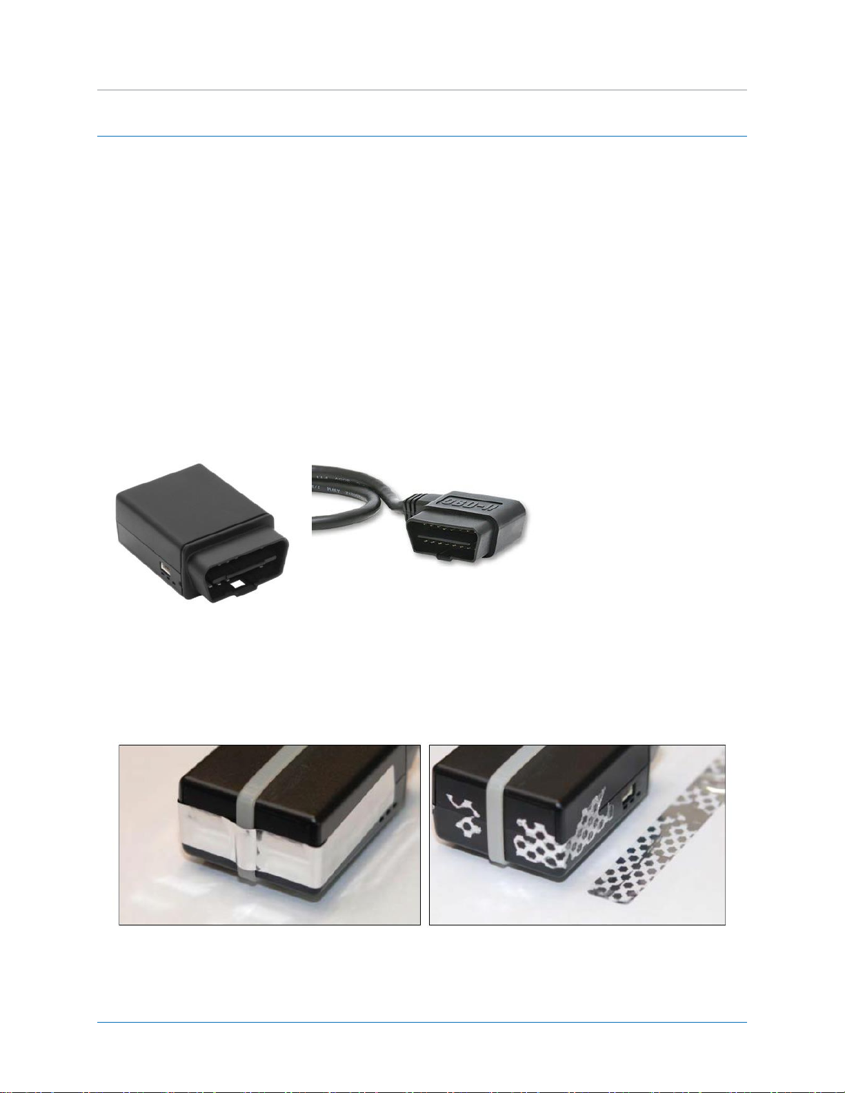
Connects to vehicle’s’ OBD-II port
Connects to LMU-30xx/CVF-3030
Figure 3: Tamper Tape Applied and Removed
Figure 2: OBD-II Extender Cable - (6ft, P/N 144301 or 2ft, P/N144302)
Figure 1: LMU-30xx/CVF-3030
Guide
3 LMU-30XX/CVF-3030 & OBD-II EXTENDER CABLE OVERVIEW
The LMU-30xx/CVF-3030 features a small size, superior GPS design, OBD-II interface, and a 3-axis
accelerometer. These features enable the LMU-30xx/CVF-3030 to access vehicle diagnostic interface
data, track vehicle speed and location, and operational information.
Typically, the LMU-30xx/CVF-3030 connects directly into the vehicle’s OBD-II port and requires no
additional connections. For protected installations, the LMU-30xx/CVF-3030 is installed under the dash,
and then is connected to an OBD-II Extender Cable (P/N 144301) that plugs directly into the vehicle’s
OBD-II port. This installation couples a zip-tie secured around the device with a tamper seal applied to
protect against accidental interference and to deter intentional tampering. When the tamper seal is
removed, the seal self-destructs to indicate removal and leaves behind a dot-pattern residue on the
device.
MBUD-0268v1.4 Page 3
Page 8

CalAmp | LMU-30xx/CVF-3030 & OBD-II Extender Cable Install Guide
General Specifications
Communication modes: cellular and SMS
Location technology: 50 channel GPS
Operating voltage: 7-20 VDC
Location Specifications
Location technology: 50 channel GPS (with SBAS, WAAS, EGNDS, MSAS, GAGAN)
Location accuracy: 2.0 meter CEP (with SBAS)
Tracking sensitivity: -160 dBm
Acquisition sensitivity: -147dBm
Certifications
Fully certified FCC, CE, IC, PTCRB, carriers
Electrical Specifications
Operating voltage: 7-20 VDC
Power consumption:
- Deep sleep: <3 mA @ 12V
- Sleep on network: <11mA
- Active tracking: <140 mA @ 12V
Physical Specifications
Dimensions approximately 1.7" x 2.5" x 1" (43 x 64 x 25 mm)
Environmental Specifications
Operating temperature: -22° to + 167° F (-30° to +75° C)
Storage temperature: -40° to 185° F (-40° to +85° C)
Humidity: 95%RH @ 50° C non-condensing
Shock and vibration: SAE J1455
EMC/EMI: SAE J1113; FCC–Part 15B; industry Canada
RoHS compliant
3.1 LMU-30xx/CVF-3030 Environmental Specifications
The LMU-30xx/CVF-3030 device is designed to operate in the following specified environments.
Page 4 MBUD-0268v1.4
Page 9

CalAmp | LMU-30xx/CVF-3030 & OBD-II Extender Cable Install
General Specifications
RoHS Compliant
All 16 pin connected
Right-angle design allows for easy use and concealment
Compatibility with the widest range of vehicle
Guide
3.2 OBD-II Extender Cable Specifications
The OBD-II Extender Cable is designed with the following specifications.
MBUD-0268v1.4 Page 5
Page 10

CalAmp | LMU-30xx/CVF-3030 & OBD-II Extender Cable Install Guide
LMU-30xx/CVF-3030 Device
OBD-II Extender Cable
6ft – P/N 144301
2ft – P/N 144302
Zip-ties: 6” or 11”
Tamper Tape
Velcro
3.3 Tools and Materials
The following materials are required for proper installation of the LMU-30xx/CVF-3030 and OBD-II
Extender Cable. No additional tools are required.
Page 6 MBUD-0268v1.4
Page 11

CalAmp | LMU-30xx/CVF-3030 & OBD-II Extender Cable Install
Guide
4 INSTALLATION
For a protected installation, the LMU-30xx/CVF-3030 device is typically installed under the vehicle
dashboard on the driver side, however, another common installation location include behind the A-pillar
panel on the driver side of the vehicle. This section outlines the steps in sequential order for installing
the components in a typical installation.
Disassemble Vehicle Panels
Installation of LMU-30xx/CVF-3030 Device and OBD-II Extender Cable
Successful Installation Verification
Reassemble Vehicle Panels
MBUD-0268v1.4 Page 7
Page 12

CalAmp | LMU-30xx/CVF-3030 & OBD-II Extender Cable Install Guide
4.1 Dissemble Vehicle Panel
The first step of the installation requires removing the panels on the driver’s side of the vehicle. The
panel you remove depends on the selected install location. The following instructions show the typical
under the dashboard panel removal.
To Remove the Panels:
1. Remove the panel above the vehicle’s OBD-II port.
Figure 4: Remove Bottom Panel
2. Place your hand on the panel indentation, and then gently pull down until the panel snaps out.
Figure 5: Bottom Panel Removed
Page 8 MBUD-0268v1.4
Page 13

CalAmp | LMU-30xx/CVF-3030 & OBD-II Extender Cable Install
Guide
3. Remove the panel behind and next to the steering column.
Figure 6: Remove Top Panel
Place your hand on the panel, and then gently pull the panel outward until the left-side of the panel
snaps out.
Once you have successfully removed the panels, continue to Step 4.2 Connect the OBD-II Extender
Cable and LMU-30xx/CVF-3030 Device.
MBUD-0268v1.4 Page 9
Page 14

CalAmp | LMU-30xx/CVF-3030 & OBD-II Extender Cable Install Guide
4.2 Connect the OBD-II Extender Cable and LMU-30xx/CVF-3030 Device
After you have successfully removed the panels, connect the OBD-II Extender Cable and LMU-30xx/CVF3030 device.
To Connect the OBD-II Extender ion Cable and LMU-30xx/CVF-3030 Device:
1. Hold the OBD-II Extender Cable by the female connector.
Figure 7: Guide the Extender Cable behind the Panel
2. Guide the OBD-II Extender Cable from below the dashboard up through the panel opening.
Figure 8: Connect the LMU-30xx/CVF-3030 Device
3. Connect the LMU-30xx/CVF-3030 device to the female connector of the OBD-II Extender Cable.
Page 10 MBUD-0268v1.4
Page 15

CalAmp | LMU-30xx/CVF-3030 & OBD-II Extender Cable Install
Guide
Figure 9: Tamper Tape over LMU-30xx/CVF-3030 and OBD-II Extender Cable Connection
4. To deter potential device tampering, apply a piece of tamper tape over the connection.
When the tamper tape is removed, the tape self-destructs to indicate removal and leaves behind a
residue on the device.
5. Place a female-side (loop-side) piece of Velcro on the LMU-30xx/CVF-3030 device.
Place tamper tape and Velcro on non-label side of the LMU-30xx/CVF-3030 device.
Figure 10: Plug Male Connector of OBD-II Extender Cable into OBD-II port.
6. Plug the male connector of the OBD-II Extender Cable directly into the vehicle’s OBD-II port.
7. To deter potential device tampering, apply a zip-tie and a piece of tamper tape over the connection.
8. For LMU-3000 devices only, review the status LEDs on the device for successful installation. For all
other LMU-30xx/CVF-3030 devices, review device communication status using the FO MobileInstall
app.
Note: The LMU-3030/CVF-3030 has one LED to indicate power up of the device. It does not report
device communication or status.
After you plug in the OBD-II Extender Cable, the LMU-3000 LEDs go through a boot-up cycle. After
the boot-up cycle completes, the orange and green lights blink before turning solid. The red light is
not active.
MBUD-0268v1.4 Page 11
Page 16

CalAmp | LMU-30xx/CVF-3030 & OBD-II Extender Cable Install Guide
The orange light takes approximately 45 seconds to go from a blinking state to a solid state. A solid
orange light indicates a cellular connection.
The green light takes approximately 15-45 seconds to go from a blinking state to a solid state. A solid
green light indicates the device established a GPS connection.
If the green light continues to blink, move the vehicle to an area with better coverage (e.g., outside
of a garage).
The red light displays as soon as the vehicle has an ignition on event. The red light indicates the
device is receiving engine RPM data from the vehicle bus, which indicates successful communication
with the OBD-II port.
When all 3 LEDs on the LMU-3000 are locked solid, the installation is successful.
Figure 11: Secure the Extra OBD-II Extender Cable
9. After verifying successful device installation, coil and secure with a zip-tie the extra OBD-II Extender
Cable to ensure it is out of the way of normal vehicle operations.
Figure 12: Tuck LMU-30xx/CVF-3030 Behind Panel
10. Place your fingers behind the dashboard panel, and place a male-side (hook-side) piece of Velcro on
the flat section of the panel.
11. Gently place the connected LMU-30xx/CVF-3030 device behind the dashboard panel and secure by
attaching the Velcro hooks and loops together.
Page 12 MBUD-0268v1.4
Page 17

CalAmp | LMU-30xx/CVF-3030 & OBD-II Extender Cable Install
Guide
The LMU-30xx should be placed non-label side up and not obstructed by metal.
The CVF-3030 should be place with the Air ID label side up and not obstructed by metal.
Once you have successfully connected the LMU-30xx/CVF-3030 and OBD-II Extender Cable, continue
to Step 4.3 Reassemble Vehicle Panels.
4.3 Reassemble the Vehicle Panel
The last step of the installation process is to reassemble the vehicle panels by gently snapping the panels
back in place.
To Reassemble Vehicle Panels:
1. Verify all connections and cable are secure and out of the way of normal vehicle operations.
Figure 13: Snap Dashboard Panel Back in Place
2. Gently snap top dashboard panel back in the place, and then verify the cable is not in sight.
Figure 14: Snap Bottom Panel Back in Place
3. Place hands on the front of the bottom panel, and then push up until panel snaps in place.
MBUD-0268v1.4 Page 13
Page 18

CalAmp | LMU-30xx/CVF-3030 & OBD-II Extender Cable Install Guide
4. To deter potential device tampering, apply a piece of tamper tape over the OBD-II port connection
(not shown).
When the tamper tape is removed, the tape self-destructs to indicate removal and leaves behind a
residue on the device.
Reassembly of vehicle panels is now complete.
Page 14 MBUD-0268v1.4
Page 19

CalAmp | LMU-30xx/CVF-3030 & OBD-II Extender Cable Install
Figure 15: FO MobileInstall Example Screens
Guide
5 FO MOBILEINSTALL APP
After completing the physical device installation, use the FO MobileInstall app to test device
communication and create a device-to-vehicle assignment in FleetOutlook. Using your smartphone or
tablet, scan the Device ID (ESN) and vehicle VIN. The FO MobileInstall app will create the device-tovehicle assignment in FleetOutlook. The device will not report in FleetOutlook until it’s assigned to a
vehicle in FleetOutlook.
Note: To use the FO MobileInstall app, you must have valid FleetOutlook login credentials. Your
MobileInstall login credentials are the same as your FleetOutlook login credentials. Additionally, your
FleetOutlook user role must include Vehicle Creation and Driver Assignment permissions.
MBUD-0268v1.4 Page 15
Page 20

CalAmp | LMU-30xx/CVF-3030 & OBD-II Extender Cable Install Guide
6 LO MOBILE INSTALL APP
After completing the physical device installation, use the LO MobileInstall app to test device
communication and create a device-to-vehicle assignment in LenderOutlook.
Tap the MobileInstall icon on your phone or tablet’s screen. The MobileInstall Login screen displays.
Using your LenderOutlook login credentials, enter your Username and Password, and then tap the Login
button. After a successful login, the Select Account screen displays. From this screen, you can drill-down
to select a sub-account, if these are available to you. This screen displays all the accounts to which you
have access. Tap the Plus icon to expand the list and view sub-accounts. Tap the Minus icon to collapse
the list and only view the main account. Verify that you have the correct account selected. Once you
have selected an account, MobileInstall starts the 4-step Installation Process.
Using your phone or tablet’s camera, you can quickly scan the device’s Air ID or ESN. Additionally, you
can also tap in the device ID field, and then manually enter the Air ID or ESN using the displayed keypad.
Scan Air ID or ESN
1. Tap the Camera icon.
2. Hold the mobile phone or tablet’s camera over the Air ID or ESN.
3. A red line and yellow dots appear on the screen. Position and hold the red line over the Air ID or ESN.
4. Your phone or tablet’s camera automatically scans the Air ID or ESN.
5. Tap Next at the bottom of the screen.
6. MobileInstall displays an Air ID or ESN confirmation message. If the Air ID or ESN is correct, tap Yes.
Figure 16: Air ID
Page 16 MBUD-0268v1.4
Page 21

CalAmp | LMU-30xx/CVF-3030 & OBD-II Extender Cable Install
Guide
Enter Vehicle Details
1. Tap in the Asset Name field, and then enter the vehicle name.
* This name is used to identify the vehicle throughout LenderOutlook.
2. Tap in the Description field, and enter a short vehicle description.
3. Tap the Camera icon next to the VIN field, and then hold the mobile phone or tablet’s camera over
the vehicle’s VIN. You can also tap in the VIN field, and then enter the VIN using the keypad.
* After the vehicle’s VIN is scanned, MobileInstall automatically populates the Make and Model fields.
You can manually edit these fields if necessary.
4. Tap the Camera icon next to the License field, and then hold the mobile or tablet’s camera in front of
the vehicle’s license plate. Tap or press the OK button on your mobile phone or tablet to save the tag
number in the License field.
5. Enter the State and vehicle’s Year.
* Depending on your organization, you may have two additional fields. These are user-defined fields.
6. Tap Next at the bottom of the screen.
Figure 17: Enter Vehicle Details
Test Your Install
At the top of this screen, MobileInstall displays if the device is communicating, number of GPS satellites
that the device has acquired and the device’s cellular signal strength. Additionally, the device’s last
reported location is displayed. Tap the Refresh icon to update the device’s location. Note: Each time you
MBUD-0268v1.4 Page 17
Page 22

CalAmp | LMU-30xx/CVF-3030 & OBD-II Extender Cable Install Guide
locate the vehicle, you use one action. If your device includes the Enable Starter and/or Payment
Reminder options, follow the testing steps below.
1. Tap the Disable Starter button. MobileInstall sends the disable starter command to the device.
2. After approximately 60 seconds, test the vehicle’s starter to verify it is disabled.
3. Tap the check box next to Disable Starter to indicate that the command passed.
4. Run the Enable starter command, wait 60 seconds, and verify the vehicle started.
5. Repeat Steps #1-3 for each command to test.
6. When finished verifying install, tap Next at the bottom of the screen.
Figure 18: Test Install
Apply Alerts and Geozones
1. You can only assign the default alerts and geozones configured in LenderOutlook for the selected
account.
2. 1. To assign alerts to the vehicle, tap the Apply Default Alerts check box.
3. 2. To assign the vehicle to a geozone group, select the geozone group from the Apply Geozone
Group drop-down list.
4. 3. Tap the Finish Install button.
5. * MobileInstall installs the device and applies any default settings selected. When finished,
MobileInstall displays a confirmation message.
* If you have more devices to install, tap the “Install Another Device?” button at the bottom of the
screen (not pictured here).
Page 18 MBUD-0268v1.4
Page 23

CalAmp | LMU-30xx/CVF-3030 & OBD-II Extender Cable Install
Guide
Figure 19: Apply Geozones
7 VERIFY DEVICE COMMUNICATION
After successful device installation in a vehicle, verify device communication using the Breadcrumb
Detail module in FleetOutlook. This is a two-step process and requires a user to be signed in
FleetOutlook. First, force the device to send in an Ignition On event by turning the ignition key to the
forward position. Second, open the Breadcrumb Detail for the corresponding vehicle in FleetOutlook. If
the device is reporting properly, you should see an Ignition On event.
Note: To report location-based data and events in FleetOutlook, each device must have a vehicle
assignment. Use the FO MobileInstall app to scan the Device ID (ESN) and vehicle VIN. The app will
automatically create the device-to-vehicle assignment in FleetOutlook.
Figure 20: FleetOutlook Reporting Verification
MBUD-0268v1.4 Page 19
Page 24

CalAmp | LMU-30xx/CVF-3030 & OBD-II Extender Cable Install Guide
8 DIAGNOSTIC AND VEHICLE MAINTENANCE
Prior to performing vehicle maintenance, disconnect the OBD-II Extender Cable from the vehicle’s OBD-II
Port. Once the OBD-II Extender Cable is removed, access to the vehicle bus data is available.
When vehicle maintenance is complete, plug the OBD-II Extender Cable back into the vehicle’s OBD-II
port. To deter device tampering, remove any existing residue from the device, and then place a new
piece of tamper tape over the connection.
Page 20 MBUD-0268v1.4
Page 25

CalAmp | LMU-30xx/CVF-3030 & OBD-II Extender Cable Install
Guide
9 WARRANTY
CalAmp Corp. warrants that upon shipment to Customer from supplier’s facility and for the Warranty
Period, hereinafter defined, the Equipment shall be free from defective materials and faulty
workmanship and capable of accessing the Service ("Good Working Order"). The warranty provided
herein shall not apply to (i) hardware normally consumed in operation such as fuses, cables, or
mounting brackets, (ii) defects which, due to no fault of CalAmp Corp, are the result of improper use or
maintenance of the Equipment, (iii) improper operation of the Equipment used with other equipment,
(iv) Equipment which, due to no fault of CalAmp, has been subjected to any kind of detrimental
exposure or has been involved in any accident, fire, explosion, Act of God, or any other cause not
attributable to CalAmp, (v) any Equipment which has been altered or repaired by any party other than
CalAmp without CalAmp’s prior consent, (vi) any Equipment sealed against the weather whereby the
seal has been broken without CalAmp’s prior consent, or (vii) any Equipment hardware or software,
including any revisions provided by CalAmp, which has been improperly stored, installed or
implemented. Customer shall de-install and return (unless otherwise directed by CalAmp) the failed
Equipment to CalAmp. CalAmp shall return the Equipment, or a new or reconditioned unit, at CalAmp’s
option, free of charge to Customer via best way ground, unless otherwise specified by Customer (with
additional costs thereof to Customer’s account), during the one year from shipment ("Warranty
Period"). CalAmp’s warranty obligation is limited to restoring the Equipment to Good Working Order.
The repaired or replacement Equipment is warranted for the remainder of the original Warranty Period.
MBUD-0268v1.4 Page 21
Page 26

CalAmp | LMU-30xx/CVF-3030 & OBD-II Extender Cable Install Guide
Contacting Customer Support
Phone:
866.456.7522 – Select #1 for Installation Support
Support Email:
solutionsupport@calamp.com
10 CUSTOMER SUPPORT CONTACT INFORMATION
CalAmp’s Customer Support team stands beside you to ensure any concerns you have with any element
of your solution – application, hardware or operations – are addressed quickly and completely.
U.S.-based 24x7x365 via toll-free number or email.
Fully trained representatives with multiple tiers of escalation.
E-mail acknowledgment and status visibility of your issue 100% of the time.
Page 22 MBUD-0268v1.4
 Loading...