

Page 1

User Manual
Feature: Bluetooth Support
CalAmp BlueBoard User Manual
FCC ID: APV-BRD01
IC: 5843A-BRD01
Version:
1.0
Page #:
1 of 20
Page 2

User Manual
Feature: Bluetooth Support
Created by: Boris Velv
1 Introduction ........................................................................................................................ 3
2 Description .......................................................................................................................... 3
3 Setup ................................................................................................................................... 4
3.1 LMU BT LE driver streams and serial port configuration parameters setup example.
4
Version:
1.0
Page #:
2 of 20
3.2 LMU BTST SPP driver streams and serial port configuration parameters setup
example. ................................................................................................................................. 4
3.3 LMU Bluetooth driver configuration parameters setup. ............................................ 5
3.4 LMU user serial message configuration parameters setup example......................... 6
3.5 BTCS version format. ................................................................................................... 7
3.6 BTCS default Pass key. ................................................................................................. 7
3.7 Verification of LMU BTST SPP mode “Data” state example. ...................................... 7
3.8 Verification of LMU configuration for BLE “connection” mode example. ................. 8
3.9 Verification of LMU BLE “Advert broadcast scanning” mode configuration
example. ................................................................................................................................. 8
4 Usage .................................................................................................................................. 9
4.1 Demonstration of LMU BT SPP mode. ........................................................................ 9
4.2 Demonstration of BLE “connection” mode based remote temperature sensor
device. .................................................................................................................................... 9
4.3 Demonstration of BLE “broadcast scanning” mode based remote KeyFob DriverID
device. .................................................................................................................................. 11
5 PWA Label ......................................................................................................................... 11
6 Integration Instructions .................................................................................................... 12
7 License Agreement ........................................................................................................ 12
8 Limited Warranty ............................................................................................................ 17
9 Regulatory Information .................................................................................................. 19
Page 3

User Manual
Feature: Bluetooth Support
1 Introduction
This application note documents the use of Bluetooth chipset device based on TI
MSP430F5438A microcontroller and CC2564 RF processor. The BTCS device has Bluetooth
LE4.0 dual mode capabilities. The firmware is based on Stonestreet One Bluetopia protocol
stack. The document uses as an example the Texas Instruments CC 2541 Sensor Tag with the
purpose of reading the temperature from TI TMP006 temperature sensor. A “KeyFob”
device which broadcasts “Button xx press” events together with “battery charge state as
percentage“ information is used as another example.
Version:
1.0
Page #:
3 of 20
2 Description
The BTCS device is connected to a LMU serial port. The BTCS unit supports Bluetooth SPP
mode of operation. BTCS plays a server slave device which upon connection with a Remote
Bluetooth client master device can exchange data. There are two Bluetooth low energy
(BLE) modes of operation: “Connection” based and an “Advert Broadcast Scanning” mode.
In “Connection” mode, the LMU firmware starts the discovery process of all BLE remote
devices. If a match is found based on the remote address stored as an “APP PARAM 2082”,
the discovery sequence is ended and the connection process starts. Upon the reception of
“CONNECTED_OK” event, the user will be able to send setup commands to the remote
device, and consequently receive the sensor data.
In “Advert Broadcast scanning” mode BT driver simply receives the broadcast
advertisements from all remote BLE devices.
The block diagram is presented in Figure 1 below.
Page 4
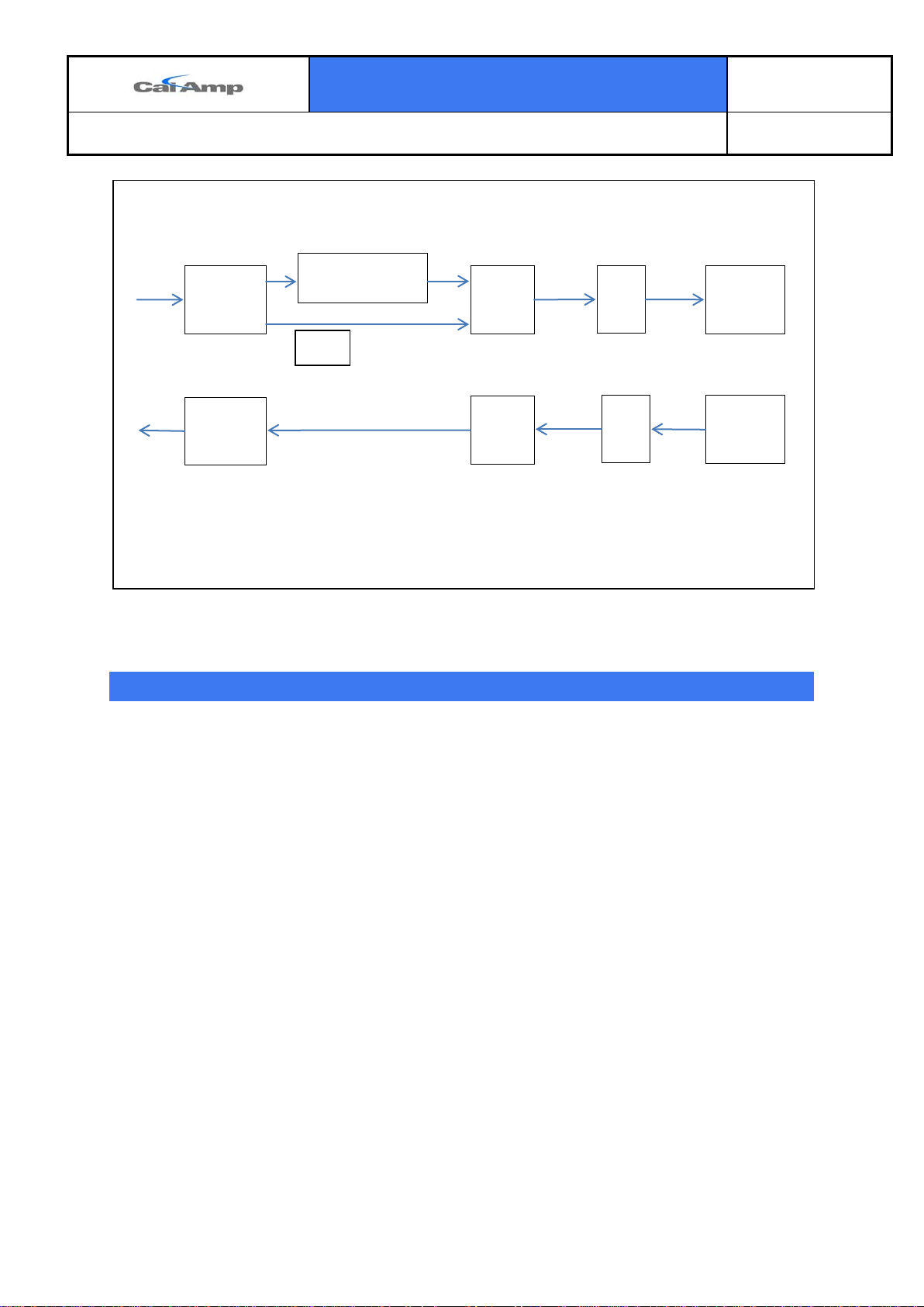
BLE “AT cmd” Parser
Feature: Bluetooth Support
User Serial
Tx Data
BT STREAM
SPP
User Manual
BT_DRV BT_ Sensor
BTCS
Version:
1.0
Page #:
4 of 20
User Serial
Rx Data
BT STREAM
BT_DRV
BTCS
BT_ Sensor
Figure 1
3 Setup
3.1 LMU BT LE driver streams and serial port configuration parameters
setup example.
• Map debug stream to Aux1 port.
AT$APP PARAM 3072,3,0
• Bluetooth stream to AUX 2.
AT$APP PARAM 3072,14,1
• A Bluetooth stream baud rate set to 115200
AT$APP PARAM 3073,14,12
• A Bluetooth stream set to 8, n, 1
AT$APP PARAM 3074,14,3
• User0 Stream to Bluetooth Port
AT$APP PARAM 3072,0,8
3.2 LMU BTST SPP driver streams and serial port configuration
parameters setup example.
• LMU BT driver SPP mode setup:
at$app param 2083,0,0
Page 5

User Manual
Feature: Bluetooth Support
• Turn off stream for User 0:
at$app param 3072,0,255
• Map Debug stream to BT_port:
at$app param 3072,3,8
• Reset LMU :
ATRESET
LMU debug log will be visible on BT remote Android device console upon connection.
The connection process is initiated by Android master device.
3.3 LMU Bluetooth driver configuration parameters setup.
• PID 2082 holds up to 8 remote device addresses 6 Bytes long.
at$app param 2082,0,144,89,175,10,169,169 corresponding to remote device MAC
address: 0x9059AF0AA9A9
The first location in the array of addresses above is used to establish a BLE
connection to a remote BLE device in BLE” Connected” mode.
All unused addresses must contain 255,255,255,255,255,255.
Version:
1.0
Page #:
5 of 20
• PID 2083 holds the mode of operation and it is 2 Bytes long. Bit 0 is used for mode
selection 0- standard-SPP, and 1- Low Energy.
For instance to configure BT driver in SPP mode use the following:
at$app param 2083,0,0
For example in order to configure BT driver in BLE “Connection” mode use:
at$app param 2083,0,1
Bit 1 defines if broadcast scanning is enabled 0 – disabled , 1 – enabled.
Bit 2: 0- whitelist should be used to filter out the remote devices with MAC
addresses which are not found in the list of the remote addresses. BTCS ignores the
whitelist functionality at present.
1: scan all advert broadcasts, no whitelist.
For instance in order to configure BT driver in “LE advert broadcast scan all” mode
use:
at$app param 2083,0,7
• To disable Bluetooth driver use:
at$app param 2083,0,65535
• The above commands allow the LMU to switch from one mode to another without
the necessity of AT reset command, given that the data stream configuration is not
changed. It could take up to 40s to complete the switch.
Page 6

User Manual
Feature: Bluetooth Support
3.4 LMU user serial message configuration parameters setup example.
• If user data packets from the remote device are required to be transmitted to the
backend server at a rate above one per five seconds, the User Message Disposition
S-Register must be set to unacknowledged Message:
S-137< VALUE = 5>
ats137=5
• Configure serial message filters:
at$app param 2178,0,""
at$app param 2178,1,""
at$app param 2178,2,""
at$app param 2178,3,""
at$app param 2178,4,""
at$app param 2178,5,""
at$app param 2178,6,""
at$app param 2178,7,""
Use the same as above for 2176 app param:
at$app param 2176,0,""
at$app param 2176,1,""
at$app param 2176,2,""
at$app param 2176,3,""
at$app param 2176,4,""
at$app param 2176,5,""
at$app param 2176,6,""
at$app param 2176,7,""
Version:
1.0
Page #:
6 of 20
• Ensure that these new configurations do not cause any stream conflicts. Send the
query:
at$app stream?
Below is an example of a stream conflict:
at$app stream?
Stream Port Rate Word
------ ---- ---- --- 0:User0 8:BTPort 9600 8/N/1
1:Modem 4:Radio 115200 8/N/1
2:User1 - 3:Debug 0:Aux1 115200 8/N/1 PREEMPT
4:NMEA Out - 5:DUN --
Page 7

Feature: Bluetooth Support
6:PEG Serial - 7:VBUS - 8:GPS Rcvr 5:GPS 115200 8/N/1
9:AltMdm 1:Aux2 115200 8/N/1
10:HostApp0 -11:HostApp1 -12:HostApp2 -13:Undef. -14:BlueTooth 1:Aux2 115200 8/N/1
15:Undef. -16:Undef. -17:Undef. -18:Undef. -19:Undef. --
OK
AUX2 must only have one stream assigned to it, so the AltMdm stream must be
moved:
at$app param 3072,9,3
This command will move the AltMdm stream to the daughterboard port.
at$app param 3072,9,255 will disable it.
User Manual
Version:
1.0
Page #:
7 of 20
• Finally reset the LMU by executing: at$app reboot
3.5 BTCS version format.
Upon RESET BTCS firmware reports its version as follows:
BT: Rcv: VERSION,4.1.1.1CBA8C2A9539 with format: dcs.bts.ver.macaddr , where dcs is
Device chipset version, bts is the bluetopia stack id, ver is BTCS firmware vesrion and
macaddr is the local device MAC address.
3.6 BTCS default Pass key.
The default Pass Key is “0000”.
3.7 Verification of LMU BTST SPP mode “Data” state example.
LMU debug log will contain:
BT: Rcv: SPP,0,1
BT: Connected
From this point data exchange is possible.
Page 8

Version:
User Manual
Feature: Bluetooth Support
3.8 Verification of LMU configuration for BLE “connection” mode example.
LMU BT driver “DISCOVERED” state can be verified by observing the following debug log
lines:
“BLE rx cmd:DISCOVERY,2,9059AF0AA9A9,0,-67,1,020105”
LMU BT driver “CONNECTED” state can be verified by observing the following debug log
lines: “BLE rx cmd:CONNECT,1,1,0,9059AF0AA9A9” , where 1 is the connection handler
index, 1-Low Energy mode, 0 – not paired, 9059AF0AA9A9 – remote device address.
The line: “BLE: Connected” indicates that the connection is achieved.
It is important to note that the connection handler index is returned by BTCS and is arbitrary
number ranging from 0 to 65535. The same connection handler index must be used to send
the user messages as explained in 4.1.
ATCS? Command will return the connection handler index:
SERMSG: Rcvd Msg:
41 54 43 53 2C 31 2C 31 2C 30 2C 39 30 35 39 41 46 30 41 41 39 41 39 0D
The above debug log line when converted to ASCII format is: ATCS,1,1,0,9059AF0AA9A9
where 1: connection handler index, 1: BLE mode, 0-not paired, 9059AF0AA9A9
is the BLE remote device MAC address.
Page #:
1.0
8 of 20
3.9 Verification of LMU BLE “Advert broadcast scanning” mode
configuration example.
The debug log indicates when the final LMU BLE “Scanning” state is reached by:
BLE: Scanning
The KeyFob “Button 1 Press” event user message looks like the following:
SERMSG: Rcvd Msg:
44 49 53 43 4F 56 45 52 59 2C 32 2C 30 30 30 37 38 30 36 37 41 33 35 44 2C 30 2C 2D 36 36
2C 33 2C 30 32 30 31 30 36 2D 30 32 30 41 30 33 2D 30 35 30 31 46 46 46 46 35 42 30 31 0D
The above message when converted to ASCII format looks like the following:
DISCOVERY,2,00078067A35D,0,-66,3,020106-020A03-0501FFFF5B01, where
• 2 is the GAP advertising report type: LE Connectable and undirected, Connectable
and Scannable, 3 – LE Connectable Direct Advertisement, Connectable only, 4- LE
Scannable Indirect Advertisement, Scannable only, 5- LE Non-connectable Indirect
Advertisement, Not connectable or scannable, 6- LE Scan Response.
• 00078067CD72 is the MAC address.
• 0-public, 1- Random LE address type.
• -66 is RSSI Received Signal Strength indication value of the last packet received in
dBm.
Page 9

Feature: Bluetooth Support
• 3 is number of advertising report data entries.
• 02 is the first advertisement report data length in Bytes.
• 01 is the first report advertisement type.
• 06 is the first report advertising data byte.
• 020A03 is the second AD report.
• 0501FFFF5B01 is the third AD report.
• The user data is in the third AD report-5B: 91% battery charge remaining, 01 :Button
1 is pressed.
4 Usage
4.1 Demonstration of LMU BT SPP mode.
Follow the instructions in 3.2. Android Bluetooth SPP application starts the process
of connection with BTCS and upon completion all LMU debug log data will be visible
in Android device console. All Android input keyboard messages ending with ‘CR’
will be visible in its console.
User Manual
Version:
1.0
Page #:
9 of 20
4.2 Demonstration of BLE “connection” mode based remote temperature
sensor device.
“GPSTRAX” server is used to send User0 messages. Select route: 0 and ID: 0 as shown in
Figure 2 below
Figure 2
Page 10

User Manual
Feature: Bluetooth Support
There is a limitation of the length of the command which has to be less than 32 BYTES.
4.2.1 Send command “Enable notifications on Temperature sensor attribute profile”.
Populate the “Data” field in Figure 2 with the hexadecimal representation of ATGW,1,38,2,1
- 0x415447572C312C33382C322C31.
Where ATGW is the BTCS API for characteristic “WRITE” (GATT WRITE). It is used to write
the characteristic value or descriptor from a server when the attribute handle of the
characteristic value is known. 1 is the BTCS connection handler, and can be an arbitrary
number.
Use ATCS command to get the correct connection handler index as explained in 3.6. The rest
of the command is “SensorTag” temperature sensor specific. 38 is the SensorTag board
temperature sensor “Notification settings” handler index. 2 is the “Notifications”
configuration parameter byte length. The last field is the parameter value - 1 stands for
“Turn ON” operation , 0 for “Turn OFF”.
Version:
1.0
Page #:
10 of 20
4.2.2 Send command “Start temperature conversion”.
Populate the “Data” field in Figure 2 with the hexadecimal representation of ATGW,1,41,1,1
- 0x415447572C312C34312C312C31
The command fields description is the same as 4.1.
4.2.3 Observe the GPSTRAX server User 0 temperature data.
474154545F56414C2C312C303033372C312C342C44394646313030430D
In LMU debug log the same message can be observed:
SERMSG: RcvMsg:
474154545F56414C2C312C303033372C312C342C44394646313030430D
Converted to ASCII format the same message is: GATT_VAL,1,37,1,4,D9FF100C0D, where
1 corresponds to the connection ID ranging from 1 to 65535,
37 corresponds to the GATT characteristic handler index specific to TI temperature sensor,
1 is GATT notification,
4 is data length in Bytes,
D9FF100C0D represents the sensor data.
The data colored in yellow represent the temperature, where 0xD9 is the lowest significant
byte of the Object temperature, 0xFF- MSB of object temperature, 0x10 – LSB of the
ambient temperature, 0x0C – MSB of the ambient temperature.
4.2.4 Disable BLE sensor “notifications”.
Populate the data field in Figure 2 with the hexadecimal representation of ATGW,1,38,2,0 0x415447572C312C33382C322C30
Page 11

User Manual
Feature: Bluetooth Support
4.2.5 Send command “Stop” temperature conversion.
Populate the data field in Figure 2 with the hexadecimal representation of ATGW,1,41,1,0 0x415447572C312C34312C312C30
4.2.6 “GPSTRAX” server report contains temperature sensor data.
Version:
1.0
Page #:
11 of 20
10/22/2013
20:21:45
486100
0011
36.7
926
0 0 0A474154545F56414C2C312C303033372C312C34
2C43444646463430420D
4.3 Demonstration of BLE “broadcast scanning” mode based remote
KeyFob DriverID device.
The GPSTRAX server report will contain the following User0 messages:
0A444953434F564552592C322C3030303738303637434437322C302C2D35352C332C30323
03130362D3032304130332D3035303146464646353430310D
Which converted into ASCII representing “Button1 press” event:
DISCOVERY,2,00078067CD72,0,-55,3,020106-020A03-0501FFFF5401
The user payload content description is given in 3.3.
The Raw message type 4 is presented below:
830548610000110101000415A25295086652950866EA11DA4C682ABBA7000000000000000
000AE0B020001FFCD4F09DD000000003D0A444953434F564552592C322C30303037383036
37434437322C302C2D35352C332C3032303130362D3032304130332D30353031464646463
53430310D
5 PWA Label
Page 12

User Manual
Feature: Bluetooth Support
6 Integration Instructions
A label containing the BlueBoard FCC ID and Industry Canada certification number must be
permanently affixed to the exterior of the host device into which the BlueBoard transmitter
is installed. The label may also be in a user accessible location such as under a panel or
battery pack if it is a handheld device, readily accessible, not placed on a removable part
and the FCC ID and Industry Canada certification number are visible at the time of purchase.
The label must contain a statement similar to the following:
o This device contains FCC ID: APV-BRD01
o This device contains IC: 5843A-BRD01
If the BlueBoard certified transmitter is intended for use in a portable use device, the OEM
integrator is responsible to design the product to comply with RF exposure requirements,
and must work with CalAmp to satisfy FCC/IC SAR requirements. Refer to Industry Canada
RSS-102 and FCC KDB publication 447498 D01 and the applicable SAR/RF Exposure KDB
publications available at:
https://apps.fcc.gov/oetcf/kdb/reports/GuidedPublicationList.cfm. 1
Version:
1.0
Page #:
12 of 20
The system user manuals and other documentation must clearly indicate operating
conditions that must be observed to ensure compliance with FCC/IC RF exposure guidelines
and also include appropriate caution and warning statements and information.
The host device containing the BlueBoard certified transmitter may also require compliance
to FCC Part 15 Subpart B – Unintentional Radiator rule part as well as Industry Canada ICES-
003.
7 License Agreement
FOR SOFTWARE, APPLICATION PROGRAMING INTERFACES (APIs) & DOCUMENTATION
IMPORTANT: DO NOT INSTALL OR USE THE SOFTWARE OR DOCUMENTATION UNTIL YOU HAVE
READ AND AGREED TO THIS LICENSE AGREEMENT.
This is a legal agreement between you, the Customer, and CalAmp DataCom Incorporated
(“CalAmp”). By installing and/or using the software or documentation, you are consenting to the
terms of this License. If you do not agree to the terms of this non-exclusive License Agreement,
DO NOT INSTALL OR USE THE SOFTWARE, APIs OR DOCUMENTATION. For a full refund,
return the unused media package and all accompanying materials within seven (7) days to
 Loading...