

Page 1

881199--GGPPRRSS--XXXXXX
GSM GPRS Serial Cellular Data Modem
User Manual
001-0003-829
Revision 1; February 2008
Page 2

Released February 2008
REVISION HISTORY
Page 3

TABLE OF CONTENTS
SECTION 1 – PREFACE
SECTION 1 – PREFACE
Copyright Notice............................................................................................................. 5
Modem Use.................................................................................................................... 5
Interference Issues......................................................................................................... 5
Mobile Application Safety.................................................................................................6
SECTION 2 – PRODUCT OVERVIEW
SECTION 2 – PRODUCT OVERVIEW
Module Identification....................................................................................................... 7
General Description ........................................................................................................ 7
Features and Benefits...................................................................................................... 7
Catalog Part Number Breakdown.......................................................................................7
External Connections ......................................................................................................8
Front panel connections ...............................................................................................8
Back panel connections................................................................................................ 8
RS-232 Serial Port Integration Parameters......................................................................9
Accessories ................................................................................................................9
SECTION 3 – GETTING STARTED
SECTION 3 – GETTING STARTED
Package Contents......................................................................................................... 10
Setting up the 819-GPRS Modem using the GPRS 819S Driver:........................................... 10
Setting up the 819-GPRS using native Windows drivers: .................................................... 14
Configuring the Modem ................................................................................................. 14
Creating a Dial-Up Networking (DUN) connection.............................................................. 14
Operational States........................................................................................................ 21
Activating your Modem.................................................................................................. 21
SECTION 4 – CALL SETUP INFORMATION
SECTION 4 – CALL SETUP INFORMATION
Circuit Switch Data (CSD) Call Setup Steps ...................................................................... 23
Packet Data Call Setup Steps ......................................................................................... 24
GPRS Internet Connection Set Up ................................................................................... 25
Internet Service Information: HTTP receive data............................................................... 26
Internet Service Information: HTTP send data .................................................................. 27
TCP Client Socket Setup ................................................................................................ 28
TCP Socket Server Setup............................................................................................... 29
UDP Client Socket Setup................................................................................................ 29
UDP Socket Listener Setup............................................................................................. 29
POP3 Generic Settings................................................................................................... 30
SMTP Generic Settings .................................................................................................. 30
FTP Upload (PUT) Setup ................................................................................................ 31
FTP Download (GET) Setup............................................................................................ 31
SECTION 5 – SIM CARD SPECIFIC INFORMATION
SECTION 5 – SIM CARD SPECIFIC INFORMATION
What to do if PIN or password authentication fails?............................................................ 33
SECTION 6 – TROUBLESHOOTING
SECTION 6 – TROUBLESHOOTING
Helpful Hints................................................................................................................ 34
Diagnosing COM Port Problems Using HyperTerminal ......................................................... 34
SECTION 7 – PROFILES
SECTION 7 – PROFILES
SECTION 8 – COMMON AT COMMAND REFERENCE GUIDE
SECTION 8 – COMMON AT COMMAND REFERENCE GUIDE
SECTION 9 – AT COMMAND REFERENCE
SECTION 9 – AT COMMAND REFERENCE
AT Command Types...................................................................................................... 39
Command Line Syntax .................................................................................................. 39
Result Codes................................................................................................................ 40
Configuration Commands............................................................................................... 40
Status Control Commands ............................................................................................. 42
Serial Interface Control Commands................................................................................. 43
Security Commands...................................................................................................... 44
Identification Commands............................................................................................... 45
Call Related Commands................................................................................................. 45
........................................................................................................ 5
...................................................................................... 7
........................................................................................ 10
............................................................................ 23
................................................................. 32
...................................................................................... 34
.................................................................................................... 36
...................................................... 37
............................................................................. 39
Page 4

TABLE OF CONTENTS
Network Service Commands........................................................................................... 47
Internal Internet Service Commands............................................................................... 50
Step-by-step instructions on how to configure and use TCP/IP communications:................. 50
Maximum number of profiles defined / used:................................................................. 50
GPRS Commands.......................................................................................................... 52
Short Message Service (SMS) Commands ........................................................................ 55
SIM Related Commands................................................................................................. 56
Hardware Related Commands......................................................................................... 57
Factory Default AT Command values ............................................................................... 58
SECTION 10 – SPECIFICATIONS
SECTION 10 – SPECIFICATIONS
General Specifications................................................................................................... 60
Data Transmission Specifications .................................................................................... 61
Mechanical Specifications............................................................................................... 62
SECTION 11 – ABBREVIATIONS
SECTION 11 – ABBREVIATIONS
SECTION 12 – SERVICE AND SUPPORT
SECTION 12 – SERVICE AND SUPPORT
Product Warranty, RMA and Contact Information............................................................... 64
RMA Request ............................................................................................................... 64
Product Documentation ................................................................................................. 64
Technical Support......................................................................................................... 64
APPENDIX 1 – WARRANTY STATEMENT
APPENDIX 1 – WARRANTY STATEMENT
........................................................................................ 60
......................................................................................... 63
............................................................................... 64
............................................................................... 65
Page 5

SSEECCTTIIOONN 11 –– PPRREEFFAACCEE
Copyright Notice
©2008 CalAmp. All Rights Reserved.
This manual covers the operation of the CalAmp 819-GPRS Serial Cellular Data Modems.
Specifications described are typical only and are subject to normal manufacturing and
service tolerances.
CalAmp reserves the right to modify the equipment, its specification or this manual without
prior notice, in the interest of improving performance, reliability or servicing. At the time of
publication all data is correct for the operation of the equipment at the voltage and/or
temperature referred to. Performance data indicates typical values related to the particular
product.
No part of this documentation or information supplied may be divulged to any third party
without the express written consent of CalAmp.
Products offered may contain software which is proprietary to CalAmp. The offer or supply
of these products and services does not include or infer any transfer of ownership.
Modem Use
The 819-GPRS modem is designed and intended for use in fixed and mobile applications.
“Fixed” assumes the device is physically secured at one location and not easily moved to
another location. Please keep the cellular antenna of the 819-GPRS at a safe distance from
your head and body while the modem is in use (see below).
Important
Maintain a distance of at least 20 cm (8 inches) between the transmitter’s antenna and any
person while in use. This modem is designed for use in applications that observe the 20 cm
separation distance.
Interference Issues
Avoid possible radio frequency (RF) interference by following these guidelines:
• The use of cellular telephones or devices in aircraft is illegal. Use in aircraft may
endanger operation and disrupt the cellular network. Failure to observe t his
restriction may result in suspension or denial of cellular s ervices to the offender,
legal action or both.
• Do not operate in the vicinity of gasoline or diesel-fuel pumps unless use has been
approved and authorized.
• Do not operate in locations where medical equipment that the device could interfere
with may be in use.
• Do not operate in fuel depots, chemical plants, or blasting areas unless use has been
approved and authorized.
• Use care if operating in the vicinity of protected personal medical devices, i.e.,
hearing aids and pacemakers.
• Operation in the presence of other electronic equipment may cause interference if
equipment is incorrectly protected. Follow recommendations for installation from
equipment manufacturers.
Page 5 of 65
001-0003-829 Revision 1
Page 6

Mobile Application Safety
• Do not change parameters or perform other maintenance of the 819-GPRS while
driving.
• Road safety is crucial. Observe National Regulations for cellular telephones and
devices in vehicles.
• Avoid potential interference with vehicle electronics by correctly installing the
819-GPRS. CalAmp DataCom recommends installation by a professional.
Page 6 of 65
001-0003-829 Revision 1
Page 7

SSEECCTTIIOONN 22 –– PPRROODDUUCCTT OOVVEERRVVIIEEWW
Module Identification
Label Information
The label contains the CalAmp DataCom part number, serial number, FCC ID, and the IMEI
number.
IMEI Dec: The International Mobile Equipment Identifier of the cellular module in decimal
format.
General Description
The 819-GPRS Cellular Data Modem from CalAmp is the ideal solution for a wide range of
cellular data network serial connectivity requirements.
The 819-GPRS version features GSM GPRS speeds. The 819-GPRS supports both circuitswitched and packet-switched services.
Features and Benefits
Supports GPRS
RS-232 connector
Quad Band GSM
TCP/IP stack access via AT commands
Circuit Switch Data Origination and Termination
PPP Originated Tethered Data Calls for TCP/IP capable devices
Packet Data transmission at speeds up to 86 kbps
JAVA Application Development Platform (J2ME)
Optimized for OEM applications
Catalog Part Number Breakdown
819-GPRS-XXX (XXX = Carrier Identifier)
GEN = Generic
Page 7 of 65
001-0003-829 Revision 1
Page 8

External Connections
Front panel connections
819-GPRS front panel indicators include:
PWR: Green LED indicating power to unit.
Tx: Red LED indicating Transmit activity.
DCD: Amber LED indicating Data Carrier Detect from cellular network.
Rx: Green LED indicating Receive activity.
RF (antenna): SMA female, primary antenna connection.
SIM: SIM Card Slot (SIM card purchased separately).
Back panel connections
Fig. 2.1 819-GPRS Front Panel
819-GPRS back panel connections include:
Power connector: 2.1mm x 5.5mm DC Barrel Jack (Center Positive)
RS-232 port: Standard DE-9 female
Fig. 2.2 819-GPRS Back Panel
Page 8 of 65
001-0003-829 Revision 1
Page 9

RS-232 Serial Port Integration Parameters
Table 2.1 provides the serial cable design information to integrate the 819-GPRS into your
system.
Table 2.1 Standard RS-232 DE-9 Pin out
Pin Name Direction Description
1 CD «— Carrier Detect
2 RX «— Receive Data
3 TX —» Transmit Data
4 DTR —» Data Terminal Ready
5 GND System Ground
6 DSR «— Data Set Ready
7 RTS —» Request to Send
8 CTS «— Clear to Send
9 RI «— Ring Indicator
Note: Direction is DTE relative DCE.
Table 2.2 Default RS-232 Communication Parameters
Bits Per Second 115,200
Data Bits 8
Parity None
Stop Bits 1
Flow Control None
Accessories
Antenna
Power Supply
4” Rubber Duck Antenna
3” Mag Mount Antenna
110 VAC input
DC Power Cable
L2-ANT0001
L2-ANT0003
L2-PWR0001
L2-PWR0002
Interface Cable Serial Cable L2-CAB0002
Primary Antenna
The primary antenna connection on the 819-GPRS is a female connector, therefore you must
purchase an antenna with a SMA male connector. Do not select a SMA antenna with “reverse
polarity” or RP-Male. When using a direct mount or “rubber duck” antenna, choose the antenna
specific to your band requirements. Mounting options and cable lengths are user’s choice and
application specific.
Page 9 of 65
001-0003-829 Revision 1
Page 10

SSEECCTTIIOONN 33 –– GGEETTTTIINNGG SSTTAARRTTEEDD
Package Contents
• 819-GPRS cellular data modem
• Information Card
Setting up the 819-GPRS Modem using the GPRS 819S Driver:
You may download all necessary modem driver files from our website at http://www.calamp.com. If
you are installing the modem using the drivers from the website, refer to these steps:
1. Click on Start --> Settings --> Control Panel. Select "Phone and Modem Opti ons".
Page 10 of 65
001-0003-829 Revision 1
Page 11

2. Select the “Modem” tab. Select “Add...” and follow the Wizard. Check “Don’t Detect My Modem”.
Page 11 of 65
001-0003-829 Revision 1
Page 12

3. Select "Have Disk…" Click “Next”.
4. Browse to the file location where the GPRS 819S modem driver was downloaded.
Page 12 of 65
001-0003-829 Revision 1
Page 13

5. Select the Siemens AG. manufacturer and MC75 Modem (GPRS) model then click “Next”.
6. Assign the modem to the COM port connected to the modem. Click “Next”.
7. Click “Finish”.
Page 13 of 65
001-0003-829 Revision 1
Page 14
Setting up the 819-GPRS using native Windows drivers:
1. Click on Start --> Settings --> Control Panel. Select "Phone and Modem Opti ons".
2. Select the “Modem” tab. Select “Add...” and follow the Wizard. Check “Don’t Detect My Modem”.
3. Select "Standard 19200 bps Modem." Click “Next”.
4. Assign the modem to the COM port connected to the modem. Click “Next”.
5. Click “Finish”.
Configuring the Modem
1. Click on Start --> Settings --> Control Panel. Select "Phone and Modem Options".
2. Click “New” or “Edit” to add or modify a location name.
3. In "Location Name", enter a name to distinguish this connection as the 819-GPRS modem. Type
your area code in the Area Code box.
4. Click "Apply" and “OK”. The window should exit out to the Phone and Modem Options box.
5. Click the tab at the top titled "Modems". Select the "MC75 Modem (GPRS)" (or the "Standard
19200 bps Modem" if you’re using the driver from the website) and click "Properties".
6. Click the "Modem" tab at the top of this new box. The box titled "Maximum Port Speed" should
read: 115200. If not, scroll down to select 115200. Click “OK”. Click "Apply".
7. Click “OK”.
Creating a Dial-Up Networking (DUN) connection
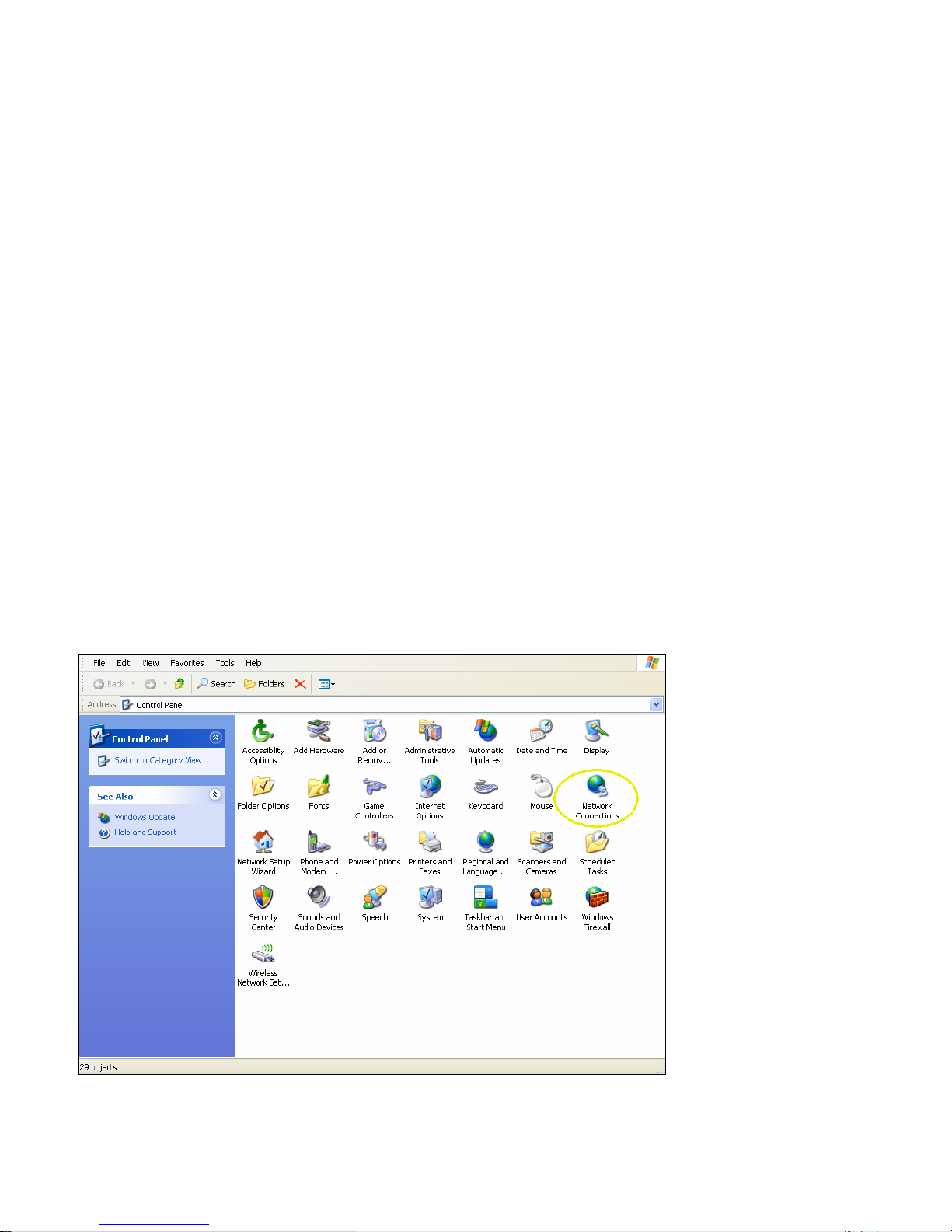
1. Click on Start --> Settings --> Control Panel. Select "Network Connections".
Page 14 of 65
001-0003-829 Revision 1
Page 15

2. From the Network Connections screen, select “Create a new connection”. Follow the Wizard as it
goes through the steps to create a dial-up connection by selecting “Next”.
3. For the connection type, select “Connect to the Internet”, then click “Next”.
Page 15 of 65
001-0003-829 Revision 1
Page 16
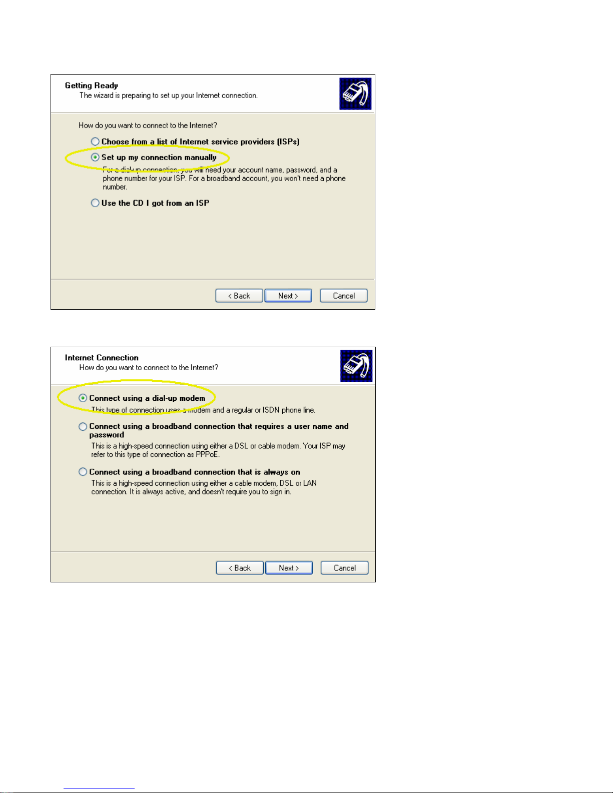
4. Select “Set up my connection manually”, then click “Next”.
5. For the internet connection, select “Connect using a dial-up modem”, then click “Next”.
Page 16 of 65
001-0003-829 Revision 1
Page 17

6. Check the box by the Modem for the GPRS device, then click “Next”.
7. Type in a connection name, then click “Next”.
Page 17 of 65
001-0003-829 Revision 1
Page 18

8. Type in *99***1# for the phone number to dial, this is the number for GPRS packet data calls.
9. Typically the username and password are left blank. Click “Next”
10. Finish off the Wizard. The network connection should now be available on the Network
Connections screen.
To check that the DUN connection is configured properly, go to the Network Connections screen and
double click on the Dial-up connection for the 819-GPRS GSM modem. The connection screen should
appear as shown below. Selecting Dial would initiate the Dial Up Connection, however, to check the
settings, select Properties.
Page 18 of 65
001-0003-829 Revision 1
Page 19

From the Properties window, confirm that the correct modem driver is checked under “Connect
using:” and select Configure...
Page 19 of 65
001-0003-829 Revision 1
Page 20

In the Configuration window, confirm that the Maximum speed (bps) is set to 115200, as shown
below. Click OK to exit out of each screen.
Refer to Packet Data Call Setup in Section 4 for further information on call setup procedures.
Page 20 of 65
001-0003-829 Revision 1
Page 21

Operational States
The modem has three operational states:
• Command State
• Online State
• Online Command State
When first powered on, the modem is in the Command State where it is able to accept AT
commands. When instructed to dial out or to answer a data call, the phone is in the Online State.
Activating your Modem
1. Connect the modem to an active COM port on a PC with an RS-232, 9 pin straight through cable.
2. Insert a SIM card with an activated account, gold contact side up. Refer to Figure 2.1, Section 2,
for card orientation.
3. Attach the antenna and power connector.
4. Connect with a Hyper-Terminal session set to 115,200, 8 Bits, No Parity, 1 Stop Bit, and
Hardware Flow Control enabled. Refer to Figure 3.1.
Figure 3.1: 819-GPRS HyperTerminal Port Settings
5. Confirm contact with the modem with the ATI command. This prints the cell module product
information. If you get an Error or no communication, verify the modem is connected to the
proper COM port and powered on. Refer to Figure 3.2.
Page 21 of 65
001-0003-829 Revision 1
Page 22

6. Verify good signal strength with the AT+CSQ command. A typical reply is +CSQ 26, 0. The first
number is signal strength and ranges from 0 to 31 (the higher the number, the stronger the
signal.)
7. Confirm your SIM card is properly installed with the AT^SCID command. A reply of ^SCID:<20
digit CID number> indicates the modem recognizes the SIM card and displays it’s ID number.
8. Confirm the phone number currently in the modem with the AT+CNUM command. It should be
11 digits i.e. 15553331234. For some carriers the phone number may not display but will
respond with “OK”. If the SIM card is not in the unit or not activated properly, the modem will
reply with “ERROR”.
9. Confirm that the SIM’s PIN has been authenticated by the network using the AT+CPIN?
command. The reply should read “+CPIN: READY”. See Section 5 for SIM related information if
“READY” does not display.
10. Verify the modems International Mobile Equipment Identity (IMEI) number with the AT+CGSN
command. The IMEI is used to identify GSM mobile equipment to the GSM network.
Figure 3.2: 819-GPRS HyperTerminal Modem Activation
If your account supports voice, you can confirm modem activation by performing a voice call to
another phone with the ATD<Cell Phone Number>; command (for example ATD15553331234; the
semicolon is required for voice calls). Your other phone should ring and the Caller ID should display
the modem’s phone number.
Configuration and test of a Circuit Switch Data (CSD) call, and Packet Data Call (TCP/IP) as well as
other internet related connections are discussed in Section 4 next.
Page 22 of 65
001-0003-829 Revision 1
Page 23

SSEECCTTIIOONN 44 –– CCAALLLL SSEETTUUPP IINNFFOORRMMAATTIIOONN
Circuit Switch Data (CSD) Call Setup Steps
1. Connect the modem to an active COM port on a PC with an RS-232 9 pin straight through cable.
2. Insert the SIM card into the unit. Be sure your account can support CSD calls.
3. Attach the antenna and power connector.
4. Connect with a Hyper-Terminal session set to 115,200, 8 Bits, No Parity, 1 Stop Bit, and
Hardware Flow Control enabled, the default speed of the modem.
5. Confirm contact with modem using AT+CGSN this prints out the IMEI of the modem (i.e.
355632004037819). If you get an Error or no communication, go to Section 7 on
Troubleshooting.
6. To auto-answer calls set ATS0=1 A value of ATS0=1 sets the modem to answer on the first
ring, where ATS0=0 disables the auto-answer feature. (NOTE: this is a letter S followed by a
Zero)
7. Specify the bearer service type, i.e. AT+CBST=7 will set type to 9600 V.32.
8. To set the Carrier Detect (DCD) to follow its connection state to the Cellular Network, set
AT&C1. The yellow DCD LED will turn on when connected to the Carrier, and turn off when not
connected. A value of AT&C0 sets CD to always be on, a value of AT&C2 sets CD to be always
on, but to wink when there is a change in the connection state.
9. Ensure that DTR is set to terminate the call and return the modem to command state on an ONto-OFF transition of DTR with AT&D2. A value of AT&D0 ignores DTR, a value of AT&D1 enters
online command state upon an ON-to-OFF transition of DTR while retaining the connected call.
10. Save the new settings in user profile with AT&W.
11. To confirm your settings, perform an AT&V. This will print out several lines of text with all the
register values.
12. Verify that you have good signal strength, AT+CSQ. A typical reply is +CSQ? 21, 0. The signal
strength (first number) ranges from 0 to 31, the higher the number the better the signal.
13. Set the modem for verbose result codes, with ATV1, this displays result codes as words, ATV0
displays result codes as numbers.
14. Confirm and that you are registered on the cellular network. Enable URC to report status of
network registration including location info rmation using the command AT+CREG=2. Type
AT+CREG?. The reply should be similar to +CREG: 2, 1, “7D0A”, “7E4D”, where the 1 indicates
registration on the home network, 7D0A is the location area code in hex, and 7E4D is the cell ID
in hex.
15. Test CSD Origination by calling your cell phone with ATD<phone number>; (for example,
ATD15075551234;). Once the phone rings and you answer the phone, you should hear sounds
similar to a fax negotiation.
16. Test CSD Termination by calling the phone number of your modem. Once it answers you should
hear sounds similar to a fax negotiation. Hang up to terminate the connection.
17. To further test CSD termination connect another modem, (landline or cellular) to another
available COM port on a PC. Configure that modem and the COM port to your required speed, i.e.
9600, with AT+IPR=9600.
18. Start HyperTerminal on the second PC’s COM port and call the LandCell modem from this
terminal window with the following command. ATD<Phone number of second 819 Modem>.
Page 23 of 65
001-0003-829 Revision 1
Page 24

19. The terminal window connected to the 819-GPRS modem, will say “RING” and then once the
modems have negotiated a connection it should say “CONNECT 9600/RPL” for a 9600 baud
connection.
20. You can now type in text in either terminal window and it will appear in the other terminal
window. This means that your modem is now answering incoming CSD data calls.
21. Type in +++ (do not hit Enter key) to enter command mode and then type ATH to disconnect
the call.
22. Once you can originate and terminate CSD calls with the modem you are ready to connect the
modem to your equipment. Please ensure that your equipment is configured to your required
data rate, i.e. 9600 bps.
Packet Data Call Setup Steps
1. Create a 19,200 Generic Modem or, use the Network Connection created in Section 3 using the
GPRS 819S Driver, and configure it for 115,200, 8 bits, no parity, 1 stop bit. Attach the modem
to an active COM port on the PC, i.e. COM1.
2. Configure the selected COM port to a maximum speed of 115,200 in the Hardware device
manager.
3. Insert the SIM card into the unit.
4. Attach the antenna and power to the 819-GPRS modem.
5. Connect it to the COM port with a 9 pin RS-232 straight through serial cable.
6. Use HyperTerminal on the COM port to set the Carrier Detect (DCD) to follow its connection state
to the Cellular Network, set AT&C1. The yellow LED will turn on when connected to the Carrier,
and turn off when not connected. A value of AT&C0 sets CD to always be on, and a value of
AT&C2 sets CD to be always on, but to wink when there is a change in the connection state.
7. Ensure that DTR is set to terminate the call and return the modem to command state on an ONto-OFF transition of DTR with AT&D2. A value of AT&D0 ignores DTR, a value of AT&D1 enters
online command state upon an ON-to-OFF transition of DTR but retains the current call.
8. Set the GPRS persistent context definitions to non-volatile by issuing the command
AT^SCFG=GPRS/persistentcontexts,1. GPRS persistent context will not be reset by AT&F.
Define the Access Point Name (APN) for the cellular provider by issuing the AT+CGDCONT=1,
IP, <APN> command (example; AT+CGDCONT=1, IP, ISP.CINGULAR).
Save the new configuration with the AT^SMSO command. This will save settings and shutdown
the module. The modem should re-start and display “^SYSSTART”.
9. To confirm your settings, perform an AT&V. This will print out several lines of text with all the
register values.
10. Confirm that you are registered on the cellular network. Enable URC to report status of network
registration including location information using the command AT+CREG=2. Type AT+CREG?.
The reply should be similar to +CREG: 2, 1, “7D0A”, “7E4D”, where the 1 indicates registration
on the home network, 7D0A is the location area code in hex, an d 7E4D is the cell ID in hex.
11. Exit HyperTerminal.
12. Create a Dial-Up Networking (DUN) connection using the modem that you created with the active
COM port, i.e. COM1 in Network and Dial-up Connections. Configure it to 115,200 bps and set
Security to Typical. Refer to Section 3.
13. Start a DUN session by double clicking on the DUN icon that was created.
Page 24 of 65
001-0003-829 Revision 1
Page 25

14. Set the username and password as defined for your carrier (usually blank).
15. Enter the phone number as *99***1# with no area code and click on Dial.
16. The modem will dial out and attempt to connect.
17. If the configured baud rate for the modem, the COM port, the modem and the DUN do not
match, the DUN will not be able to talk to the modem properly and you will get a hardware error
message. Otherwise the DUN will contact the cellular n etwork and authenticate the user on the
network.
18. Once connected you will be able to browse the Internet through the DUN session. To confirm
this, disable any other network connection you may have running.
GPRS Internet Connection Set Up
Make sure that your SIM is provisioned with GPRS data services. Insert the SIM card, attach the
antenna and serial cable, and power on the unit. Start a HyperTerminal session as described earlier.
The AT^SICS command is used to setup the Internet Connection profile. For a generic setup type
the following commands:
AT^SICS=0,alphabet,1
AT^SICS=0,contype,gprs0
Different carriers may require a specific username, password, or apn to be configured as well.
Check the settings by typing, AT^SICS?. An example output response is shown below;
^SICS: 0,"conType","GPRS0"
^SICS: 0,"alphabet","1"
^SICS: 0,"user",""
^SICS: 0,"passwd","*****"
^SICS: 0,"authMode","PAP"
^SICS: 0,"apn",""
^SICS: 0,"inactTO","20"
^SICS: 1,"conType",""
^SICS: 2,"conType",""
^SICS: 3,"conType",""
^SICS: 4,"conType",""
^SICS: 5,"conType",""
OK
The GPRS connection can be tested with a PING service and the inactivity timer <InactTo>
deactivated (by default, it is set to 20 seconds as shown in the example output). The timer can be
disabled by sending AT^SICS=0,”inactTO”,0. Open only the GPRS connection without an
associated service. The connection won't be closed until AT^SICC=0 or closed by the network
because of inactivity (4 hours on Cingular in coverage). Once the connection is open with AT^SICO,
you cannot use AT^SISO or AT^SISC. Services defined with AT^SISS using connection profile 0 will
be immediately opened by typing;
Open the connection by typing, AT^SICO=0
Wait for the “OK” response.
Page 25 of 65
001-0003-829 Revision 1
Page 26

Start the ping test using the AT^SISX command. The example pings google.com 4 times with a
timeout of 2000 ms.
AT^SISX="Ping",0,"google.com",4,2000
The response output example is shown below (the output may differ, but should show a successful
ping response);
^SISX: "Ping",1,0,"64.233.187.99",798
^SISX: "Ping",1,0,"64.233.187.99",526
^SISX: "Ping",1,0,"64.233.187.99",475
^SISX: "Ping",1,0,"64.233.187.99",471
^SISX: "Ping",2,0,4,4,0,0
^SISX: "Ping",3,0,471,798,567
OK
To close the connection type AT^SICC=0.
Internet Service Information: HTTP receive data
Once the GPRS Internet Connection profile has been setup using the AT^SICS commands, the
AT^SISS command is used to setup the Internet Service Information profile. For an HTTP service
test, type the following commands to setup a connection to receive data from yahoo.com:
AT^SISS=0,alphabet,1
AT^SISS=0,srvType,HTTP
AT^SISS=0,address,"http://www.yahoo.com"
AT^SISS=0,conId,0
Check the settings by typing, AT^SISS?. An example output response is shown below;
^SISS: 0,"srvType","Http"
^SISS: 0,"conId","0"
^SISS: 0,"alphabet","1"
^SISS: 0,"hcMethod","0"
^SISS: 0,"hcContLen","0"
^SISS: 0,"hcAuth","0"
^SISS: 0,"hcRedir","1"
^SISS: 0,"address","http://www.yahoo.com"
^SISS: 0,"hcContent",""
^SISS: 0,"hcProp","Accept-Encoding: identity"
^SISS: 0,"user",""
^SISS: 0,"passwd","*****"
^SISS: 0,"hcUsrAgent","MC75/4.1"
^SISS: 0,"tcpMR","10"
^SISS: 0,"tcpOT","6000"
^SISS: 1,"srvType",""
^SISS: 2,"srvType",""
^SISS: 3,"srvType",""
^SISS: 4,"srvType",""
^SISS: 5,"srvType",""
^SISS: 6,"srvType",""
^SISS: 7,"srvType",""
^SISS: 8,"srvType",""
^SISS: 9,"srvType",""
OK
Page 26 of 65
001-0003-829 Revision 1
Page 27

Open the connection by typing AT^SISO=0. A response should display showing that the
connection was successful, as shown below;
^SIS: 0, 3, 2201, "HTTP Response:HTTP/1.1 200 OK"
^SISR: 0, 1
The ^SISR: 0, 1 response indicates that there is data available and can be read by sending the
AT^SISR command. Send the AT^SISR commend requesting 1500 bytes of data.
AT^SISR=0,1500
The response will produce 1500 bytes of data (mostly html text) and another ^SISR: 0, 1 at the
end, indicating more data is available. Send the AT^SISR=0,1500 command until the response
reads ^SISR: 0, 2, indicating the data transfer is complete.
Check the connection state by typing AT^SISO?. An example output response is shown below;
^SISO: 0, "Http","6","1","9533","0","10.192.72.82:0","209.131.36.158:80"
^SISO: 1, ""
^SISO: 2, ""
^SISO: 3, ""
^SISO: 4, ""
^SISO: 5, ""
^SISO: 6, ""
^SISO: 7, ""
^SISO: 8, ""
^SISO: 9, ""
OK
To close the connection, type AT^SISC=0.
Internet Service Information: HTTP send data
In this example, HTTP data is sent to a fictitious server located at
http://myserver.com/mydir/myfile. Use the AT^SISS command to configure the connection profile.
AT^SISS=0,alphabet,1
AT^SISS=0,srvType,HTTP
AT^SISS=0,conId,0
AT^SISS=0,address,"http://myserver.com/mydir/myfile"
AT^SISS=0,hcMethod,1
AT^SISS=0,hcProp,"Content-Type: application/x-www-form-urlencoded" (or any other HTTP
properties)
To send data less than 128 bytes the AT^SISS=0,hcContent,”your data” can be used to send data
without using the AT^SISW command.
To send data larger than 128 bytes, first specify the size of the data by typing the following
command:
AT^SISS=0,hcContLen,xx where xx specifies the total amount of data to be sent.
Open the connection by typing, AT^SISO=0.
Check the connection state by typing, AT^SISO?.
Page 27 of 65
001-0003-829 Revision 1
Page 28

Send the data (if size > 128 bytes) by typing AT^SISW=0,<size>
Enter the data to be sent, you will get OK when all the bytes are transmitted. A response will be sent
something like:
^SIS: 0, 0, 2201, "HTTP/1.1 200 OK"
^SISR: 0, 1
Read the HTTP Answer by typing the command, AT^SISR=0,1500. This closes the connection and
give a response somewhat like the following;
^SISR: 0, 102
<the answer from the server>
OK
TCP Client Socket Setup
This example describes commands to setup the modem as a TCP Socket Client. To check that data is
received by the server, you can launch a TCP socket server on a computer with a public IP address.
Configure the modem using the following AT commands:
AT^SISS=0,srvtype,socket
AT^SISS=0,address,socktcp://'host':'remote tcpPort'[;disnagle='0|1']
For example:
AT^SISS=0,srvtype,socket
AT^SISS=0,address,socktcp://66.94.234.13:80
AT^SISS=0,conid,0
Check the configuration settings by typing, AT^SISS?.
Open the connection by typing, AT^SISO=0.
A response of “^SISW: 0,1” will indicate that you can write (or send) data on this socket. Write
some data using the AT^SISW=0,x command, where x is the number of bytes, up to 1500.
A response of "^SISR: 0,1" will indicate that you have some data to be read. The
AT^SISR=0,1500 command will read up to 1500 bytes of data.
Close the upstream data with <EodFlag> at the end of the AT^SISW command by typing,
AT^SISW=0,0,1. The upload data direction needs to be closed for the latest firmware revision
when the GSM module is done sending data.
Close connection by typing, AT^SISC=0.
Page 28 of 65
001-0003-829 Revision 1
Page 29

TCP Socket Server Setup
This example describes commands to setup the modem as a TCP Socket Server. Configure the
modem using the following AT commands:
AT^SISS=0,alphabet,1
AT^SISS=0,srvtype,socket
AT^SISS=0,address,"socktcp://listener:2000"
AT^SISS=0,conid,0
Open the connection by typing, AT^SISO=0.
Close connection by typing, AT^SISC=0.
UDP Client Socket Setup
This example describes commands to setup the modem as a UDP Socket Client. To check that data
is received by the server, you can launch a UDP socket server on a computer with a public IP
address.
Configure the modem using the following AT commands:
AT^SISS=0,srvtype,socket
AT^SISS=
For example:
AT^SISS=0,srvtype,socket
AT^SISS=0,address,"sockudp://10.48.132.11:2000"
Open the connection by typing, AT^SISO=0.
Close connection by typing, AT^SISC=0.
UDP Socket Listener Setup
This example describes the commands to setup the modem as a TCP Socket Server. Configure the
modem using the following AT commands:
AT^SISS=0,alphabet,1
AT^SISS=0,srvtype,socket
AT^SISS=0,address,"sockudp://listener:2000"
AT^SISS=0,conid,0
Open the connection by typing, AT^SISO=0.
A response of “^SISR: 0, 1” will be displayed for incoming UDP data. Type, AT^SISR=0,1500 to
read data. An example response is shown below;
^SISR: 0, 20, 0, 10.40.236.159:1024
Hello from UDP client
Replying directly using 20 bytes by typing, AT^SISW=0,20,,,10.40.236.159:1024. After
receiving the “^SISW: 0, 20, 0” type your reply and hit enter.
Close connection by typing, AT^SISC=0.
0,address,"sockudp://<REMOTE_IP>:<REMOTE_PORT>"
Page 29 of 65
001-0003-829 Revision 1
Page 30

POP3 Generic Settings
This example describes commands to setup the modem as a POP3 Server. Configure the modem
using the following AT commands:
AT^SISS=0,srvtype,pop3
AT^SISS=0,user,<USER>
AT^SISS=0,passwd,<PASSWORD>
AT^SISS=0,address,<POP3 server IP address>
AT^SISS=0,pcmd,1 (th is is the Status Command)
AT^SISS=0,conid,0
Open the connection by typing, AT^SISO=0.
Close connection by typing, AT^SISC=0.
SMTP Generic Settings
This example describes commands to setup the modem for SMTP. Configure the modem using the
following AT commands:
AT^SISS=0,alphabet,1
AT^SISS=0,srvType,Smtp
AT^SISS=0,address,<mail.email.com>
AT^SISS=0,user,<username>
AT^SISS=0,passwd,<password>
AT^SISS=0,smFrom,<sender@email.com>
AT^SISS=0,smRcpt,<receiver@email.com>
AT^SISS=0,smSubj,<Email Subject>
AT^SISS=0,smAuth,1
AT^SISS=0,conid,0
Check the profile settings by typing, AT^SISS?
Open the connection by typing, AT^SISO=0.
Write the email text using the AT^SISW command, for example, to write 24 bytes of data send the
following:
AT^SISW=0,24
<enter 24 bytes of text here>
Close the upstream data with <EodFlag> at the end of the AT^SISW command by typing,
AT^SISW=0,0,1. The upload data direction needs to be closed for the latest firmware revision
when the GSM module is done sending data.
Close connection by typing, AT^SISC=0.
Page 30 of 65
001-0003-829 Revision 1
Page 31

FTP Upload (PUT) Setup
This example describes commands to setup the modem to upload to an FTP server. The module will
support only passive mode for FTP transfers. Configure the modem using the following AT
commands:
AT^SISS=0,srvType,ftp
AT^SISS=0,conId,0
AT^SISS=0,address,"ftpput://myname:mypasswd@192.168.1.2/upload/example.bin;type=i"
The file “example.bin” will be created on the FTP server at IP 192.168.1.2.
Open the connection by typing, AT^SISO=0.
FTP service is ready for upload when “^SISW: 0, 1” is displayed.
Typing At^SISW=0,100 will request to send 100 bytes. Th e write command response confirms that
100 bytes must be transferred now.
^SISW: 0,100,100
Data can now be transferred. For example:
0123456789012345678901234567890123456789012345678901234567890123456789012345678901234
567890123456789
A response of “^SISW: 0, 1” indicates that the FTP service is ready to transfer more data. Data from
the last AT^SISW command is transferred to the remote host.
Close the upstream data with <EodFlag> at the end of the AT^SISW command by typing,
AT^SISW=0,0,1.
Close connection by typing, AT^SISC=0.
FTP Download (GET) Setup
This example describes commands to setup the modem to download from an FTP server. The
module will support only passive mode for FTP transfers. Configure the modem using the following
AT commands:
AT^SISS=0,srvType,ftp
AT^SISS=0,conId,0
AT^SISS=0,address,"ftp://login:password:@<IP address of server>/example.txt"
Open the connection by typing, AT^SISO=0.
Read the file by typing AT^SISR=0,1500 to get the first 1500 bytes of data. After “^SISR: 0,2” is
displayed, all data has been received and the connection can be closed.
Close connection by typing, AT^SISC=0.
For more information on Internet related AT commands and specifically the AT ^SISS Internet
Service Setup Profile command, consult the Siemens TC65/MC75 AT Command Set document
available from Siemens.
Page 31 of 65
001-0003-829 Revision 1
Page 32

SSEECCTTIIOONN 55 –– SSIIMM CCAARRDD SSPPEECCIIFFIICC IINNFFOORRMMAATTIIOONN
The AT+CPIN command controls network authentication of the TC65.
The read command (AT+CPIN?) returns an alphanumeric string indicating whether or not network
authentication is required.
The write command allows the modem to store the entered password. This may be for example the
SIM PIN1 to register to the GSM network, or the SIM PUK1 to replace a disabled SIM PIN1 with a
new one, or the PH-SIM PIN if the client has taken precautions for preventing damage in the event
of loss or theft etc. If no PIN1 request is pending (for example if PIN1 authentication has been done
and the same PIN1 is entered again) the modem responds "+CME ERROR: operation not allowed";
no further action is required.
Each time a password is entered with AT+CPIN the module starts reading data from the SIM. The
duration of reading varies with the SIM card. This may cause a delay of several seconds before all
commands which need access to SIM data are effective.
Users should be aware that when using a phonebook, SMS or Remote SAT command quickly after
SIM PIN authentication the SIM data may not yet be accessible, resulting in a short delay before the
requested AT command response is returned. This delay is due to the initial process of loading SIM
data once after SIM PIN authentication. The duration of loading SIM data is dependent on the SIM
card used and may take a couple of seconds.
Successful PIN authentication only confirms that the entered PIN was recognized and correct. The
output of the result code OK does not necessarily imply that the mobile is regist ered to the desired
network. Typical example: PIN was entered and accepted with OK, but the ME fails to register to the
network. This may be due to missing network coverage, denied network access with currently used
SIM card, no valid roaming agreement between home network and currently available operators etc.
The modem offers various options to verify the present status of network registration: For example,
the AT+COPS? command indicates the currently used network. With AT+CREG you can also check
the current status and activate an unsolicited result code which appears whenever the status of the
network registration changes (e.g. when the ME is powered up, or when the network cell changes).
The <pin> and <new pin> can also be entered in quotation marks (e.g. "1234").
To check the number of remaining attempts to enter the passwords use the AT^SPIC command.
See AT+CPWD and AT^SPWD for information on passwords, Section 9, Table 9.6.
See AT+CLCK and AT^SLCK for information on lock types, Section 9, Table 9.6.
To query and change the status of the SIM’s PIN enter the following AT commands:
AT+CMEE=2 Will enable error messages to be displayed as text.
AT+CLCK=”SC”,2 Will display the status of the PIN, 0=lock is inactive, 1=lock is active
AT+CPIN=xxxx Will verify that PIN xxxx is valid.
AT+CLCK=”SC”,0,xxxx Will set the PIN to “lock inactive”, where xxxx is the current active PIN
Page 32 of 65
001-0003-829 Revision 1
Page 33

What to do if PIN or password authentication fails?
PIN1 / PUK1:
After three failures to enter PIN 1, the SIM card is blocked (except for emergency calls). +CME
ERROR: 12 will prompt the client to unblock the SIM card by entering the associated PUK (= PIN
Unblocking Key / Personal Unblocking Key). After ten failed attempts to enter the PUK, the SIM card
will be invalidated and no longer operable (the device will respond with: +CME ERROR: 770, which
stands for: SIM invalid - network reject). In such a case, the card needs to be replaced. PIN1
consists of 4 to 8 digits, PUK1 is an 8-digit code only.
To unblock a disabled PIN1 you have two options:
• You can enter AT+CPIN=PUK1,new PIN1.
• You can use the ATD command followed by the GSM code **05*PUK*newPIN*newPIN#;.
Phone lock:
If the mobile was locked to a specific SIM card (= "PS" lock or phone lock), the PUK that came with
the SIM card cannot be used to remove the lock. After three failed attempts to enter the correct
password, ME returns +CPIN: PH-SIM PUK (= response to read command AT+CPIN?), i.e. it is now
waiting for the Master Phone Code. This is an 8-digit device code associated to the IMEI number of
the mobile which can only by obtained from the manufacturer or provider. When needed, contact
Siemens AG and request the Master Phone Code of the specific module.
There are two ways to enter the Master Phone code:
• You can enter AT+CPIN=Master Phone Code
• You can use the ATD command followed by the GSM code *#0003*Master Phone Code#;.
Usually, the Master Phone Code will be supplied by mail or e- mail. If the received number is
enclosed in the *# codes typically used for the ATD option, it is important to crop the preceding
*#0003* characters and the appended #.
Example: You may be given the string *#0003*12345678#. When prompted for the PH-SIM PUK
simply enter 12345678. If incorrectly input, the Master Phone Code is governed by a specific timing
algorithm: (n-1)*256 seconds. The timing should be considered by system integrators when
designing an individual MMI.
Refer to Section 9, Security Commands, for more information.
For more detailed information, refer to the Siemens TC65/MC75 AT Command Set document
available from Siemens.
Page 33 of 65
001-0003-829 Revision 1
Page 34

SSEECCTTIIOONN 66 –– TTRROOUUBBLLEESSHHOOOOTTIINNGG
In this section, you will find important information relating to the setup and diagnosis of your 819GPRS modem. If you are having trouble communicating with the modem, please read this
"Troubleshooting" section in full. If, after reviewing this section, you are still having problems
connecting, call our Technical Support line at: 507-833-8819 for more assistance. Toll charges may
apply.
Helpful Hints
Only assign one device to any given COM port on your system.
The 819-GPRS data modem has a default COM port speed of 115,200 bps. This is the data rate at
which your modem connects to your computer. The modem's COM port speed can be lowered to
300bps or raised to 230,400 bps. Warning: Please ensure your COM port is capable of 230,400 data
rates before changing the modem to this speed. As this setting adjusts the communications speed
that the modem utilizes to speak to the computer, altering this parameter must be performed in a
very specific way, otherwise, you may lose communication with the modem. To alter the defau lt
speed of 115,200 bps, first, connect via your terminal emulation software (settings: 115200bps, 8,
N, 1, Hardware). Now, you may issue the AT+IPR command to query or change the default speed.
After adjusting the port speed, disconnect from the modem and reconnect using the new data rate.
Refer to Table 9.5: Serial Interface Control Commands in Section 9 for more information pertaining
to the AT+IPR command.
Make certain the serial cable is firmly connected to an enabled COM port with no hardware resource
conflicts. Make sure that you have properly added the "MC75 Modem (GPRS)” (or the "Standard
19200 bps Modem") to your system (see Section 3 above). Also, check to see if you have an infrared
(IR) port assigned to your modem's COM port. Disable it if you are not using this function. Often, an
IR port can interfere with the COM port even after you successfully connect. Device Manager may
indicate that there is no conflict between the two, but disabling the IR port may still help.
If your system's COM port appears to be locked, you may have to shut down and reboot your
system.
Do not use "Disable Call Waiting" (commonly referred to as *70) when configuring Dialing
Properties.
Make certain that you are using the proper RS-232 serial cable. For most applications, you must use
a straight-through RS-232 serial cable. For certain types of equipment, you may be required to use a
null modem cable.
Diagnosing COM Port Problems Using HyperTerminal
If you are experiencing problems connecting to the cellula r network, you can verify if the issue is
between the computer and the modem or between the modem and the cellular network. To test,
open your terminal emulation software, such as Hyperterminal. Once the modem is ready to accept
commands, type: ATI and press enter. The product information of the modem should print out on
the screen (for example: SIEMENS, TC65, REVISION 02.000). This will confirm that you are
communicating with the LandCell modem and not some other device connected to or inside the PC.
If the product information does not print out, please confirm that you have selected the COM port
that the modem is attached to, and not some other port, internal modems typically show up as
COM3.
Page 34 of 65
001-0003-829 Revision 1
Page 35

To test the link between your modem and the cellular network try to call your cell phone. Type in:
ATD<phone number to call>; (for example ATD15075551234;) and press enter. This command
will perform a voice call similar to the type a standard home phone would make and if your modem
has been activated correctly your cell phone should ring and display the number of the modem.
Answer the incoming call on your cell phone and then hang-up your cell phone. If you are properly
communicating with the modem using the steps above and still cannot connect through the cellular
network, here are a few items to check:
• Call the phone number of the modem. If the phone number is not active, the cellular service
will inform you of this.
• Confirm that the IMEI on the Label matches the IME I in the module with AT+CGSN This will
print out the IMEI of the Modem in Decimal format, ie 355632004037819. This rarely
happens, but if the numbers do not match, the wrong IMEI may be in your Account.
• Contact your cellular provider and make certain that the International Mobile Electronic
Identity (IMEI) of the modem is active in their system.
• Check the signal strength reaching the modem using the following command: AT+CSQ A
typical reply is +CSQ? 19,99. The signal strength (first number) ranges from 0 to 31, the
higher the number the better the signal.
• Issue the command: AT^SCID to verify that the SIM card is in the modem and installed
properly. The number should match the ICCID of the issued SIM card.
• Attempt to relocate the modem and/or antenna to receive a stronger signal.
NOTE: Running diagnostics from Modem Properties may not work if the computer attempts to
communicate with the modem at an improper baud rate.
Page 35 of 65
001-0003-829 Revision 1
Page 36

SSEECCTTIIOONN 77 –– PPRROOFFIILLEESS
In addition to the default profile, you can store an individual one with AT&W. To alternate between
the two profiles enter either ATZ (loads user profile) or AT&F (restores factory profile).
NOTE: Every ongoing or incoming call will be terminat ed.
Table 7.1: Profile Commands
AT&V
Returns the current parameter setting. The configuration varies depending on
whether or not PIN authentication has been done.
Stores the currently set parameters to a user defined profile in the nonvolatile memory. The user defined profile will be restored automatically after
AT&W
power-up. Use ATZ to restore user profile and AT&F to restore factory
settings. Until the first use of AT&W, ATZ works as AT&F. AT&W stores all
global settings and the current local settings of the interface, on which the
command is executed.
AT&F
ATZ
Sets all current parameters to the manufacturer defined profile. Refer to
Section 8, Table 8.1.
Sets all current parameters to the user profile stored with AT&W. If a
connection is in progress, it will be terminated.
Page 36 of 65
001-0003-829 Revision 1
Page 37

SSEECCTTIIOONN 88 –– CCOOMMMMOONN AATT CCOOMMMMAANNDD RREEFFEERREENNCCEE GGUUIIDDEE
Below you will find a reference guide of the AT commands most commonly used in
day-to-day operation of the modem.
Table 8.1: Common AT Commands
Command Description
Configuration Commands
AT&F Set all current parameters to manufacturer defaults
AT&V Display current configuration
AT&W Stores current configuration to user defined profile
Extended Configuration Settings
AT^SCFG
Example to enable Persistent Context when setting APN:
AT^SCFG=GPRS/PersistentContexts, 1
ATZ
Sets all current parameters to the user profile stored with AT&W. If a connection is
in progress, it will be terminated.
Serial Interface Control Commands
Set fixed local baud rate
The write command specifies the bit rate to be used for the interface. When you
AT+IPR
set a fixed-rate, make sure that both TE (DTE) and TA (DCE) are configured to the
same rate.
Example: AT+IPR=19200 sets the modem baud rate to 19200.
Security Commands
AT+CPIN? PIN Authentication status. Example response; +CPIN: READY
Identification Commands
Display product identification
Example:
ATI
SIEMENS
TC65
REVISION 02.000
AT+CGSN
AT+CNUM
AT^SCID
Request International Mobile Equipment Identity (IMEI)
This is the module IMEI number located on the top label.
Read own numbers
Example response; +CNUM: “My Number”, “18052054436”, 129
Display SIM card identification number
Example response; ^SCID: 89014104211640012345
Call Related Commands
ATA Answer a Call
Mobile originated call to specified number
ATD
ATD<phone number>; for voice call test. Example: ATD15075551234;
ATD<phone number> for data call. Example: ATD15075551234
ATD*99***1# Establish a GPRS connection by service code 99 and using CID 1.
ATH Disconnect exsiting connection
Switch from command mode (ie AT commands) to data mode/PPP online mode.
This command is only available during a CSD call or a GPRS connection . The +++
character sequence causes the TA to cancel the data flow over the AT interface
ATO
and switch to command mode. This allows you to enter AT commands while
maintaining the data connection to the remote device or, accordingly, the GPRS
connection. To prevent the +++ escape sequence from being misinterpreted as
data, it must be preceded and followed by a pause of at least 1000 ms. The +++
characters must be entered in quick succession, all within 1000 ms.
+++ Switch from data mode to command mode
Page 37 of 65
001-0003-829 Revision 1
Page 38

Network Service Commands
AT+CSQ
At^SMONG
GPRS Service Commands
AT+CGACT
AT+CGATT
AT+CGDATA
AT+CGDCONT
AT+CGPADDR
Miscellaneous Commands
A/ Repeat previous command line
Signal Quality
Example response; +CSQ: 25,0 has an RSSI of -63 dBm
Cell Info Table
Example response:
GPRS Monitor
BCCH G PBCCH PAT MCC MNC NOM TA RAC # Cell #
0637 1 - 4 234 05 2 00 0B
BCCH - ARFCN of BCCH carrier
G - GPRS status:
0 GPRS not available in currently used cell
1 GPRS available in currently used cell
2 GPRS attached
PBCCH - If PBCCH is present, indication of ARFCN, else ''-''
PAT - Priority Access Threshold (GSM Rec. 04.08 / 10.5.2.37b)
0 Packet access is not allowed in the cell
1 Spare, shall be interpreted as "000" (packet access not allowed)
2 Spare, shall be interpreted as "000" (packet access not allowed)
3 Packet access is allowed for priority level 1
4 Packet access is allowed for priority level 1 to 2
MCC - Mobile Country Code
MNC - Mobile Network Code
NOM - Network Operation Mode (1...3)
TA - Timing Advance Value
RAC - Routing Area Code (as hexadecimal value)
PDP context activate or dactivate
? - Read command returns the current activation states for all the defined PDP
contexts.
=0 – Write command is used to deactivate the specified PDP context.
=1 - Write command is used to activate the specified PDP context.
GPRS attach or detach
? - Read command returns the current GPRS service state.
=0 – Write command is used to detach the MT to the GPRS service.
=1 - Write command is used to attach the MT to the GPRS service.
Enter GPRS data state
=? - List of supported <L2P>s
=<L2P>,<cid>, Example: AT+CGDATA=”PPP”,1
Define PDP Context
=? - Read command returns the current settings for each defined PDP context.
=<cid>, “IP”,<APN>,<PDP Address>,0,<PDP Header Commpression>
Example: AT+CGDCONT=1,”IP”,isp.cingular sets ‘isp.cingular’ as the APN
Show PDP address
=<cid>, Example response; +CGPADDR: 1, “15.144.187.50”
Page 38 of 65
001-0003-829 Revision 1
Page 39

SSEECCTTIIOONN 99 –– AATT CCOOMMMMAANNDD RREEFFEERREENNCCEE
All modem functions are controlled using the same industry-standard AT commands that are used to
control landline modems. A knowledge of all these commands is not required by most users, but are
provided here as a reference.
AT Command Types
There are several types of AT commands as defined in the following list;
• Configuration Commands
• Status Control Commands
• Serial Interface Control Commands
• Security Commands
• Identification Commands
• Call Related Commands
• Network Service Commands
• Internet Service Commands
• GPRS Commands
• Short Message Service (SMS) Commands
• SIM Related Commands
• Hardware Related Commands
The parameters set by the various AT commands in this section are applied to all subsequent calls
and will be used each time you place a call. As such, your custom settings (if not saved in a profile)
will be available until you power down the modem. These settings are lost upon powerdown
if not saved. For further information, refer to the Siemens TC65/MC75 AT Command Set document
available from Siemens.
Command Line Syntax
The "AT" or "at" prefix must be set at the beginning of each command line. To terminate a command
line enter <CR>.
Commands are usually followed by a response or, result codes, that includes
"<CR><LF><response><CR><LF>".
Table: 9.1 Command Syntax
AT command type Syntax Function
The mobile equipment returns the list of parameters
Test command AT+CXXX=?
and value ranges set with the corresponding Write
command or by internal processes.
Read command AT+CXXX?
This command returns the currently set value of the
parameter or parameters.
Write command AT+CXXX=<...> This command sets user-definable parameter values.
Exec(ution)
command
AT+CXXX
The execution command reads non-variable
parameters determined by internal processes in the
GSM engine.
Commands may be edited using the backspace key, but the backspace will not delete th e AT
attention command at the beginning of the command line.
Page 39 of 65
001-0003-829 Revision 1
Page 40

Result Codes
After issuing a command, a result code will typically be displayed on the screen to inf orm you if the
command was successful, unsuccessful, improperly formatted, etc. When in the command mode,
thirteen possible result codes may be returned. The result codes can be set to display as either digits
or words by accessing the Verbose command, ATV. The digit code is returned when the Verbose
mode is OFF (ATV0); the word code is returned when Verbose is ON (ATV1). See table 9.2 for more
information on Verbose format.
Table: 9.2 Result Codes
Numeric Verbose Description
0 OK Command executed without errors.
1 CONNECT Link established.
2 RING Ring detected.
3 NO CARRIER Link not established or disconnected.
4 ERROR Invalid command or command line too long.
6 NO DIALTONE No dial tone, dialling impossible, wrong mode.
7 BUSY Remote station busy.
47 CONNECT 2400/RLP Link with 2400 bps and Radio Link Protocol.
48 CONNECT 4800/RLP Link with 4800 bps and Radio Link Protocol.
49 CONNECT 9600/RLP Link with 9600 bps and Radio Link Protocol.
50 CONNECT 14400/RLP Link with 14400 bps and Radio Link Protocol.
ALERTING Alerting at called phone
DIALING Mobile phone is dialing
Configuration Commands
These commands control the basic configuration of the modem. The parameters can only be read
back by the AT&V command when in command state. The following table shows the command
format.
Table 9.3: Configuration Commands
Command Description
AT&F Sets all current parameters to the manufacturer defined profile.
Returns the current parameter setting. The configuration varies depending on
AT&V
AT&W
ATQ
ATV
ATX
whether or not PIN authentication has been done and whether or not Multiplex
mode is enabled
Stores the currently set parameters to a user defined profile in the non-volatile
memory.
Set result code presentaion mode:
0 - DCE transmits result code
1 - Result codes are suppressed and not transmitted
This command determines the contents of header and trailer transmitted with
AT command result codes and information responses.
0 – Numeric Result Code information response
1 – Verbose Result Code information response
Set CONNECT result code format and call monitoring:
0 - CONNECT result code only returned, dial tone and busy detection are both
disabled.
1 - CONNECT <text> result code only returned, dial tone and busy detection are
both disabled.
Page 40 of 65
001-0003-829 Revision 1
Page 41

2 - CONNECT <text> result code returned, dial tone detection is enabled, busy
detection is disabled.
3 - CONNECT <text> result code returned, dial tone detection is disabled, busy
detection is enabled.
4 - CONNECT <text> result code returned, dial tone and busy detection are both
enabled.
Set CONNECT result code format:
AT\V
ATZ
AT+CFUN
AT^SMSO Initiates the power-off procedure.
AT+GCAP Request complete TA capabilities list.
AT+CMEE
AT+CSCS
AT^SCFG
AT^SM20
0 - CONNECT <text> result code returned without RLP trailer.
1 - CONNECT <text> result code returned with RLP trailer.
Sets all current parameters to the user profile stored with AT&W. If a
connection is in progress, it will be terminated.
Sets phone functionality:
AT+CFUN=0 NON-CYCLIC SLEEP mode
AT+CFUN=1 Full functionality
AT+CFUN=7 CYCLIC SLEEP mode, In this mode, the serial interface is shortly
enabled while CTS is active. If characters are recognized on the serial interface,
the ME stays active for 2 seconds after the last character was sent or received.
ME exits SLEEP mode only, if AT+CFUN=1 is entered.
AT+CFUN=9 CYCLIC SLEEP mode, In this mode, the serial interface is shortly
enabled while CTS is active. If characters are recognized on the serial interface,
the ME stays active after the last character was sent or received for at least the
time, which can be configured by
AT^SCFG="PowerSaver/Mode9/Timeout",<psm9to> (temporary wakeup). In
contrast to SLEEP mode 7 assertion of RTS can also be used to temporarily wake
up the ME.
Mobile Equipment Error Message Format:
AT+CMEE=0 Disable result code, i.e. only "ERROR" will be displayed.
AT+CMEE=1 Enable error result code with numeric values.
AT+CMEE=2 Enable error result code with verbose (string) values.
Select TE character set:
AT+CSCS=“GSM“ GSM default alphabet (GSM 03.38 subclause 6.2.1); Note:
This setting may cause software flow control problems since the codes used to
stop and resume data flow (XOFF = decimal 19, XON = decimal 17) are
interpreted as normal characters.
AT+CSCS=“UCS2“ 16-bit universal multiple-octet coded character set
(ISO/IEC10646 [32]); UCS2 character strings are converted to hexadecimal
numbers from 0000 to FFFF; e.g. "004100620063" equals three 16-bit
characters with decimal values 65, 98 and 99, $(AT R97)$
Extended Configuration Settings:
The AT^SCFG? read command returns a list of all supported parameters and
their current values.
The AT^SCFG= write command queries a configuration parameter (if no value
is entered) or sets its value(s). Input of parameter names is always coded in
GSM character set, parameter values are expected to be given as specified via
AT+CSCS.
Sets M20 compatibility mode:
AT^SM20=<CallMode>, <CmgwMode>
0 - Set compatibility to Siemens mobile phones.
1 - Default mode
Page 41 of 65
001-0003-829 Revision 1
Page 42

Status Control Commands
The AT Commands described in this section allow the ext ernal application to obtain various status
information from the modems cellular module.
Table 9.4: Status Control Commands
Command Description
Mobile Equipment Event Reporting:
AT+CMER=<mode>,0,0,<ind>,0
Mode:
0 - Discard "+CIEV" and "^SLCC" URCs.
1 - Discard "+CIEV" and "^SLCC" URCs when TA-TE link is reserved, e.g. in
online data mode. Otherwise they are forwarded directly to the TE.
2 - Buffer "+CIEV" and "^SLCC" URCs in the TA wh ile TA-TE link is reserved,
e.g.
AT+CMER
AT+CIND
AT^SIND
AT+CEER
ATS18
AT+CPAS
in online data mode, and flush them to the TE afterwards. Otherwise they are
forwarded directly to the TE.
3 - Forward "+CIEV" and "^SLCC" URCs directly to the TE. If TC65 is in online
data mode, URCs are signaled via sending BREAK (100ms) and stored in a
buffer. Once it is back in command mode e.g. after +++ was entered, all URCs
stored in the buffer will be output.
Ind:
0 - Disable indicator event reporting.
2 - Enable indicator event reporting.
The command controls the presentation of Indicator Event Reports related to
various functions such as battery charge level, signal quality, service
availability, sound generation, indication of unread short messages, full SMS
storage, call in progress or roaming activities.
The read command provides a list of all indicators supported by AT+CIND and
AT^SIND. Each indicator is represented with its registration mode and current
value.
The write command can be used to select a single indicator in order to modify
its registration and to view the current value.
The command returns an extended error report regarding the reason of the last;
• call release
• failure to set up a call (both mobile originated or terminat ed)
• failure to modify a call by using Supplementary Services
• failed attempt to activate, register, query, deactivate or deregister a
Supplementary Service
• unsuccessful GPRS attach or unsuccessful PDP context activation
• GPRS detach or PDP context deactivation
Controls the presentation of extended call release reports for circuit switched
fax and data calls. Extended call release reports related to voice calls are
controlled via AT+CEER.
Mobile equipment activity status:
0 - Ready
3 - Incoming call (ringing)
4 - Call in progress or call hold
Page 42 of 65
001-0003-829 Revision 1
Page 43

Serial Interface Control Commands
The AT Commands described in this section allow the ext ernal application to determine various
settings related to the modems's serial interface.
Table 9.5: Serial Interface Control Commands
Command Description
Flow control:
0 - Disable flow control
1 - XON/XOFF software flow control
AT\Q
AT&C
AT&D
AT&S
ATE
AT+ICF
AT+IFC
2 - Only CTS by DCE (TA)
3 - RTS/CTS hardware flow control
Recommended for the following procedures: incoming or outgoing data calls,
fax calls, MUX mode. Often, the initialization routine of Fax programs includes
enabling RTS/CTS handshake, eliminating the need to issue AT\Q3 once again.
Set circuit Data Carrier Detect (DCD) function mode:
0 - DCD line is always ON
1 - DCD line is ON in the presence of data carrier only
Set circuit Data Terminal Ready (DTR) function mode:
0 - TA ignores status of DTR.
1 - ON->OFF on DTR: Change to command mode while retaining t he connected
call.
2 - ON->OFF on DTR: Disconnect data call, change to command mode. During
state DTR = OFF auto-answer is off.
Set circuit Data Set Ready (DSR) function mode:
0 - DSR line is always ON
1 - TA in command mode: DSR is OFF.
TA in data mode: DSR is ON.
Enable command echo:
0 - Echo mode off
1 - Echo mode on
Serial Interface Character Framing:
=5,1 7 bits, even parity, 1 stop bit
=5,0 7 bits, odd parity, 1 stop bit
=2,1 8 bits, even parity, 1 stop bit
=3 8 bits, no parity, 1 stop bit
=2,0 8 bits, odd parity, 1 stop bit
=1 8 bits, no parity, 2 stop bits
Set Flow Control separately for data directions:
AT+IFC=<TEflowcontrol>, <TAflowcontrol>
TEflowcontrol:
0 - none
1 - XON/XOFF, terminate flow control in the Cellular Engine
2 - RTS line
3 - XON/XOFF, evaluate flow control in the Cellu lar Engine and pass it through
(over the air) to the opposite TE
TAflowcontrol:
0 - none
1 - XON/XOFF
2 - CTS line
Page 43 of 65
001-0003-829 Revision 1
Page 44

Set TE-TA local rate reporting:
0 - Disables reporting of local port rate
AT+ILRR
AT+IPR
AT^STPB
Security Commands
The AT Commands described in this section allow the ext ernal application to determine various
security related settings.
Table 9.6: Security Commands
Command Description
AT+CPIN
AT+SPIC
AT+CLCK
AT+CPWD
1 - Enables reporting of local port rate
300, 600, 1200, 2400, 4800, 9600, 14400, 19200, 28800, 38400, 57600,
115200, 230400, 460800 rates supported
Set fixed local rate:
300, 600, 1200, 2400, 4800, 9600, 14400, 19200, 28800, 38400, 57600,
115200, 230400, 460800 rates supported
Transmit Parity Bit (for 7E1 and 7O1 only):
0 - The parity bit will not be transmitted over the air an d will be replaced with 0.
This mode is the default setting if 7E1 or 7O1 is activated with AT+ICF.
1 - In a data connection 8 bits will be transmitted, includ ing the parity bit, i.e.
the parity bit will be properly transmitted over the air. The setting shall be used
if problems are encountered when TC65 is running in the default 7E1 or 7O1
mode enabled with AT+ICF. In this case, AT^STPB=1 shall be set in addition to
the 7E1 or 7O1 settings selected with AT+ICF.
PIN Authentication:
AT+CPIN? command returns an alphanumeric string indicating whether or not
network authentication is required.
AT+CPIN=<pin>,<new pin> command allows the modem to store the entered
password.
Display PIN counter:
Command used to find out whether the ME is waiting for a password and, if so,
how many attempts are left to enter the password.
Facility lock:
Command can be used to lock, unlock or interrogate a network or ME <facility>.
The command can be aborted when network facilities are being set or
interrogated. The facility for the SIM PIN is “SC”.
Change Password:
AT+CPWD=<facility>, <old password>, <new password>
Command allows user to define a new password for a password protected
<facility> lock function. Each password is a string of digits, the length of which
varies with the associated <facility>. The test command returns a list of pairs
which represent the available facilities and the maximum length of the
associated password. The facility for the SIM PIN is “SC”.
Page 44 of 65
001-0003-829 Revision 1
Page 45

Identification Commands
The AT Commands described in this section allow the ext ernal application to obtain various
identification information related to the modem and linked entities.
Table 9.7: Identification Commands
Command Description
The execute command delivers product information text.
ATI
AT+CGMI Request manufacturer identification (GSM 07.07)
AT+GMI Request manufacturer identification (V.250)
AT+CGMM Request model identification (GSM 07.07)
AT+GMM Request model identification (V.250)
AT+CGMR Request revision identification of software status (GSM 07.07)
AT+GMR Request revision identification of software status (V.250)
AT+CGSN Request International Mobile Equipment Identity (IMEI) (GSM 07.07)
AT+GSN Request International Mobile Equipment Identity (IMEI) (V.250)
AT+CIMI Request International Mobile Subscriber Identity (IMSI) (GSM 07.07)
Call Related Commands
The AT Commands described in this section are related to Mobile Originat ed (MOC, i.e. outgoing)
Calls and Mobile Terminated (MTC, i.e. incoming) Calls.
Table 9.8: Call Related Commands
Command Description
ATA
ATD
ATDI
ATDL Redial last number used in the ATD command.
ATH Disconnect existing connection
AT+CHUP Cancels all active and held calls. (Hang up call)
AT+SHUP Hang up call(s) indicating a specific GSM04.08 release cause.
ATS0
ATS6
The 'Revision' information consists of the following parts: Version xx and variant
yy of software release.
Answer a call:
TA causes remote station to go off-hook (e.g. answer call).
Mobile originated call to specified number:
This command can be used to set up outgoing voice, data or fax calls.
ATD<n><mgsm>
n:
String of dialing digits and optional V.250 modifiers: 0-9, *, #, +, A, B, C The
following V.250 modifiers are ignored: ,(comma), T, P, !, W ,@ Emergency call :
<n> = 112, 911 or 08, standardized GSM emergency number (no SIM needed).
mgsm(optional):
String of GSM modifiers:
I - Activates CLIR (disables presentation of own phone number to called party)
i - Deactivates CLIR (enables presentation of own phone number to called party)
G - Activate Closed User Group explicit invocation for this call only.
g - Deactivate Closed User Group explicit invocation for this call only.
Mobile originated call to ISDN number:
ISDN number: String with maximum length of 20 characters. Allowed
characters: +, 0-9, A, B, C.
Set number of rings before automatically answering a call:
=000 Automatic answer mode is disabled.
=001-255 Enable automatic answering after specified number of rings.
Set pause before blind dialing:
=000 to 255
Page 45 of 65
001-0003-829 Revision 1
Page 46

ATS7
ATS8
ATS10
ATO
+++
AT+CBST
AT+CRLP Select radio link protocol parameters for originated non-transparent data calls.
AT+CLCC
AT+CR
At+CRC
Set number of seconds to wait for connection completion:
=000 to 060
Set number of seconds to wait for comma dialing modifier:
=0 DCE does not pause when "," encountered in dial string
=1 to 255 Number of seconds to pause
Set disconnect delay after indicating the absence of data carrier:
=001 to 254 Number of tenths of seconds of delay
Switch from command mode to data mode / PPP online mode:
ATO is the corresponding command to the +++ escape sequence: When you
have established a CSD call or a GPRS connection and TA is in command mode,
ATO causes the TA to resume the data or GPRS connection and takes you back
to data mode or PPP online mode.
Switch from data mode to command mode:
This command is only available during a CSD call or a GPRS connection. The
+++ character sequence causes the TA to cancel the data flow over the AT
interface and switch to command mode. This allows you to enter AT commands
while maintaining the data connection to the remote device or, accordingly, the
GPRS connection. To prevent the +++ escape sequence from being
misinterpreted as data, it must be preceded and followed by a pause of at least
1000 ms. The +++ characters must be entered in quick succession, all within
1000 ms.
Select bearer service type:
AT+CBST=<speed>
speed:
=1 300 bps (V.21)
=2 1200 bps (V.22)
=4 2400 bps (V.22bis)
=6 4800 bps (V.32)
=7 9600 bps (V.32)
=14 14400 bps (V.34)
=65 300 bps (V.110)
=66 1200 bps (V.110)
=68 2400 bps (V.110)
=70 4800 bps (V.110)
=71 9600 bps (V.110)
=75 14400 bps (V.110)
List current calls of ME:
The execute command returns a list of current calls of ME. If comman d is
successful, but no calls are available, no information response is sent to TE.
Service reporting control:
Configures the TA whether or not to transmit an intermediate result code +CR:
<serv> to TE when a call is being set up.
=0 Disable
=1 Enable
Setting the value to 1 may lead to connection failure, if t he application (e.g.
WinFax) waits for default result code/URC.
Set Cellular Result Codes for incoming call indication :
The command controls whether or not to use the extended format of incoming
call indication.
=0 Disable extended format
=1 Enable extended format
Setting the value to 1 may lead to connection failure, if t he application (e.g.
WinFax) waits for default result code/URC.
Page 46 of 65
001-0003-829 Revision 1
Page 47

Single Numbering Scheme:
The command enables the ME to accept incoming calls when no bearer
capability information is provided with the call, e.g. sin gle numbering scheme
calls or calls originitating from analog devices.
=0 Voice: Each call received without bearer element is assumed to be speech
AT+CSNS
AT^SCNI
AT^SLCD
AT^STCD
ATP Select pulse dialing.
ATT Select tone dialing.
Network Service Commands
The AT Commands described in this section are related to various network services. For futher
information, refer to the Siemens TC65/MC75 AT Command Set document available from Siemens.
Table 9.9: Network Service Commands
Command Description
AT+COPN
AT+COPS
=2 Fax: Each call received without bearer element is assumed to be an
incoming fax.
=4 Data: Each call received without bearer element is assumed to be a data
call. Please take into account that the bearer service parameters set with
AT+CBST applies to all data calls including those received with out bearer
capability.
List Call Number Information:
TA returns a list of current calls of ME.
Display Last Call Duration:
TA returns last call duration or current call duration.
Display Total Call Duration:
TA returns total call duration (accumulated duration of all calls).
Read operator names:
The command returns the list of operator names from the ME.
Operator Selection:
The command queries (?) the present status of the modem's network
registration and sets whether automatic or manual network selection shall be
used.
AT+COPS=<mode>, <format>, <oper>
mode:
0 - Automatic mode; <oper> field is ignored.
1 - Manual operator selection
Write command requires <oper> in numeric format, i.e. <format> shall be 2.
Read command returns the current <mode> and the currently selected <oper>.
If no operator is selected, <format> and <oper> are omitted.
2 - Manually deregister from network and remain unregistered until <mode>=0
or 1 or 4 is selected.
3 - Set only <format> (for AT+COPS read command).
4 - Automatic / manual selection; if manual selection fails, automatic mode
(<mode>=0) is entered (<oper> field will be present).
format:
0 - Long alphanumeric format of <oper>. Can be up to 16 characters long.
2 - Numeric format of <oper>. This is the GSM Location Area Identification (LAI)
number, which consists of the 3-digit Mobile Country Code (MCC) plus the 2- or
3-digit Mobile Network Code (MNC).
oper:
Name in numeric format
Page 47 of 65
001-0003-829 Revision 1
Page 48

AT^SOPS Extended Operator Selection similar to At^COPS.
Network registration:
The read (?) command serves to verify the network registration status of the
ME.
0 - Not registered, ME is currently not searching for new operator and user
intervention is required. Yet, emergency calls can be made if any network is
available.
1 - Registered to home network
2 - Not registered, but ME is currently searching for a new operator
3 - Registration denied, Either the SIM or the MS or the ME are unable to log
into any network. No further attempt is made to search or log into a network.
AT+CREG
AT+CSQ
AT^SMONC
AT^SMOND
AT^MONI
User intervention is required. Emergency calls can be made, if any network is
available.
4 - Unknown (not used)
5 - Registered, roaming. The ME is registered at a foreign network (nat ional or
international network)
The write command is as follows:
=0 Disable +CREG Unsolicited Result Codes (URC)
=1 Enable URC +CREG:<stat> to report status of network registration
=2 Enable URC +CREG:<stat>[,<lac>,<ci>] to report status of network
registration including location information. Optional paramet ers <lac> and <ci>
will not be displayed during calls or if these values have not changed since last
AT+CREG read command or since last indication by +CREG URC
Signal quality:
The execute command indicates the received signal strength <rssi> and the
channel bit error rate <ber>.
rssi:
0 -113 dBm or less
1 -111 dBm
2..30 -109... -53 dBm
31 -51 dBm or greater
99 not known or not detectable
ber:
0..7 as RXQUAL values
99 not known or not detectable
Cell Monitoring:
The execute command delivers cell information containing 9 values from a
maximum of 7 base stations. The first base station is the serving cell.
Cell Monitoring:
The execute command can be used to obtain status information of the service
cell and up to six neighbour cells. The advantage over other cell monitoring
commands is that AT^SMOND delivers more detailed information about the
received signal strength.
Monitor idle mode and dedicated mode:
The command supplies information of the serving/dedicated cell. Th ere are two
ways to retrieve the information: once on request by using the execute
command or automatically every <period> seconds by using the write
command. To stop the periodic presentation type "AT" or "at".
=1 to 254 periods in seconds
Page 48 of 65
001-0003-829 Revision 1
Page 49

AT^MONP
AT^SMONG
AT^SHOM
AT^SPLM
AT+CPOL
AT^SPLR
AT^SPLW
Monitor neighbour cells:
The command supplies information of up to six neighbour cells. There are two
ways to retrieve the information: once on request by using the execute
command or automatically every <period> seconds by using the write
command. To stop the periodic presentation type "AT" or "at".
=1 to 254 periods in seconds
GPRS Monitor:
The command supplies GPRS specific cell information. There are two ways to
retrieve the information: once on request by using the execute command or
automatically every <period> seconds by using the write command. To stop the
periodic presentation type "AT" or "at".
=1,1 to 100 periods in seconds
Display Homezone:
The returns the homezone state. The result is valid only , if network registration
state <stat> is 1 (registered) (see AT+CREG).
0 - ME is out of Homezone
1 - ME is within the Homezone
Read the PLMN list:
The execute command returns the list of operators from the ME.
Preferred Operator List:
The read command returns the list of the preferred operators.
The write command allows user to edit the list of the preferred operators. If
<index> is given but <operator> is left out, the entry is deleted. An operator
can be only once in the list.
AT+CPOL=<index>, 2, <operator>
index:
The order number of the operator in the SIM preferred operator list.
operator:
Operator in numeric format (GSM Location Area Identification number which
consists of a 3-digit country code plus a 2- or 3-digit network code).
Read entry from the preferred operators list:
The write command returns used entries from the SIM list of preferred operators
with <indexa> between <index1> and <index2>. If <index2> is not given, only
entry at <index1> is returned. The test command returns the whole index range
supported by the SIM.
AT^SPLR=<index1>, <index2>
index1:
Location number to start reading from
index2:
Location number where to stop reading
Write an entry to the preferred operators list:
The write command writes an entry to the SIM list of preferred operators at
location number <index>. If <index> is given but <oper> is left out, the entry
is deleted. An operator can be only once in the list. Test command returns the
whole index range supported by the SIM.
AT^SPLW=<index>, <oper>
index:
location number
oper:
Operator in numeric format (GSM Location Area Identification number which
consists of a 3-digit country code plus a 2- or 3-digit network code).
Page 49 of 65
001-0003-829 Revision 1
Page 50

Internal Internet Service Commands
The modem has an embedded TCP/IP stack that is driven by AT commands and enables the host
application to easily access the Internet. The advantage of this solution is that it eliminates the need
for the application manufacturer to implement their own TCP/IP and PPP stacks, thus minimizing cost
and time to integrate Internet connectivity into a new or existing host application. This Section is a
reference guide to all the AT commands and responses defined for use with the TCP/IP stack. Access
is provided to the following Internet Services:
1. Socket Client and Server for TCP, Client for UDP
2. FTP Client
3. HTTP Client
4. SMTP Client
5. POP3 Client
Step-by-step instructions on how to configure and use TCP/IP communications:
• First of all, create a connection profile with AT^SICS. The connection profile is a set of basic
parameters which determines the type of connection to use for an Internet service. Up to 6
connection profiles can be defined, each identified by the <conProfileId>.
• Secondly, use AT^SISS to create a service profile based on one of the connection profiles. Up to
10 service profiles can be defined, each identified by the <srvProfileId>. The service profile
specifies the type of Internet service to use, i.e. Socket, FTP, HTTP, or one of the email services
SMTP or POP3. To assign a connection profile to a service profile, the <conProfileId> of AT^SICS
must be entered as "conId" value of the AT^SISS parameter <srvParmTag>. This offers great
flexibility to combine connection profiles and service profiles. For ex ample, you may have one
connection profile (CSD or GPRS) specified with AT^SICS which can be associated w it h an SM TP
service profile for sending emails and a POP3 service profile for retrieving emails.
• Once the connection profile and the service profile are created, an Internet session can be opened
by entering the AT^SISO write command and the desired <srvProfileId>. Wait for the resulting
URC.
• The next command determines the action to be performed, for example reading data with
AT^SISR or writing data with AT^SISW. Wait for the resulting URC.
• Finally, to end a session, enter the AT^SISC write command and the <srvProfileId>.
Maximum number of profiles defined / used:
• Up to 6 connection profiles can be created (with AT^SICS).
• Up to 10 service profiles can be created (with AT^SISS), but the number of parallel profiles of the
same service type is limited as listed below. If the maximum number of a service prof ile type is
already defined, any attempt to set up another profile for t he same type will be denied with
"+CME ERROR: unknown".
- Maximum 3 HTTP profiles
- Maximum 6 socket profiles: Only 2 instances can be opened for listener, meaning that if 2
listeners are established another 4 instances can be opened for clients. Also, the socket
service can accept an incoming connection only when at least one service profile is still free
(not yet created with AT^SISS), otherwise the incoming connection will be rejected from the
listener. If there is no listener established all 6 socket profiles can be configured as client.
- 1 FTP profile
- 1 POP3 profile
- 1 SMTP profile
Page 50 of 65
001-0003-829 Revision 1
Page 51

• The TCP/IP stack of TC65 supports using several service profiles at the same time, prov ided all of
them are running on the same connection profile. For example, it is possible to download files
from an FTP server, while sending and receiving emails at the same time.
• GPRS connections established over the Dial-Up Network do not use the embedded TCP/IP stack of
TC65 and can be active at the same time. This allows the user to have two parallel GPRS
connections: for example, for sending or receiving emails over a GPRS connection enabled by the
TCP/IP stack while, at the same time, surfing the Internet over a Dial-Up Network GPRS
connection.
Address notation
Server addresses must be provided as IP addresses in standard dot-format (e.g. "192.168.1.2") or
as server address names resolvable by a DNS server (e.g. "smtp.myserver.de" or
"pop3.myserver.de").
Inactivity timeouts
Inactivity timeouts are not part of the Internet AT command functionality implemented in the
modem and, if desired, are the responsibility of the host application. It is recommended that the
host application validates URCs and AT command responses and reacts adequately, for example by
sending a close message or starting a timer.
A brief description of the internet service commands are provided in Table 9.10. For futher
information, refer to the Siemens TC65/MC75 AT Command Set document available from Siemens.
Table 9.10: Internet Service Commands
Command Description
AT^SICS
AT^SISS
AT^SISO
AT^SISC
AT^SISR
AT^SISW
At^SISX
Internet Connection Setup Profile:
The command serves to create and edit Internet connection profiles.
Internet Service Setup Profile:
The command serves to set up the necessary parameters in the Internet service
profiles.
Internet Service Open:
The write command starts the Internet session configured by the service profile.
Internet Service Close:
The write command performs all necessary action to release all properties
activated by AT^SISO.
Internet Service Read Data:
The write command triggers reading data via the Internet service configured
with AT^SISS.
Internet Service Write Data:
The write command triggers writing data via the Internet service configured
configured with AT^SISS.
Internet Service Execution:
The write command sends ICMP (Internet Control Message Protocol) Echo
Requests to a target IP address or host name (also referred to as Ping
command).
AT^SISX=”Ping”,0,<host name or IP address>
Page 51 of 65
001-0003-829 Revision 1
Page 52

GPRS Commands
This Section describes AT Commands that a TE (Terminal Equipment, e.g. an application running on
a controlling PC) may use to control the modem acting as a GP RS Mobile Termination (MT).
A brief description of the GPRS commands are provided in Table 9.11. For futher information, refer
to the Siemens TC65/MC75 AT Command Set document available from Siemens.
Table 9.11: GPRS Commands
Command Description
PDP context activate or deactivate:
The test command is used for requesting information on the supported PDP
context activation states.
The read command returns the current activation states for all the defined PDP
contexts.
The write command is used to activate or deactivate the specified PDP
context(s). After the command has completed, the MT remains in V.250
AT+CGACT
AT+CGANS
AT+CGATT
command state. If any PDP context is already in the requested state, the state
for that context remains unchanged. If the MT is not GPRS attached when the
activation form of the command is executed, the MT first performs a GPRS
attach and then attempts to activate the specified contexts. If no <cid>s are
specified the activation/deactivation form of the command activates/deactivates
all defined contexts.
=0 deactivated
=1 activated
Manual response to a network request for PDP context activation:
The write command requests the MT to respond to a network request for GPRS
PDP context activation which has been signaled to the TE by the RING or CRING
unsolicited result code. The <response> parameter allows the TE to accept or
reject the request.
=0 the request is rejected and the MT returns OK to the TE
=1 accept and request that the PDP context be activated
GPRS attach or detach:
The test command is used for requesting information on the supported GPRS
service states.
The read command returns the current GPRS service state.
The write command is used to attach the MT to, or detach the MT from the
GPRS service. After the command has completed, the MT remains in V.250
command state. If the MT is already in the requested state, the command is
ignored and the OK response is returned. Any active PDP contexts will be
automatically deactivated when the attachment state changes to detached.
=0 detached
=1 attached
Page 52 of 65
001-0003-829 Revision 1
Page 53

Automatic response to a network request for PDP context activation:
The test command returns the values of <n> supported by the MT as a
compound value.
The write command disables or enables an automatic positive response (autoanswer) to the receipt of a Request PDP Context Activation message from the
network. It also provides control over the use of the V.250 basic commands
ATS0, ATA and ATH for handling network requests for PDP context activation.
=0 Disable automatic response for network requests for GPRS PDP context
AT+CGAUTO
AT+CGDATA
AT+CGDCONT
AT+CGEQMIN 3G Quality of Service Profile (Minimum acceptable)
AT+CGEQREQ 3G Quality of Service Profile (Requested)
AT+CGPADDR Show PDP address
AT+CGQMIN Quality of Service Profil e (Minimum acceptable)
AT+CGQREG Quality of Service Profile (Requested)
activation. GPRS network requests are manually accepted or rejected by the
AT+CGANS command.
=1 Enable automatic response for network requests for GPRS PDP context
activation. GPRS requests are automatically accepted according to the
description below.
=3 Modem compatibility mode. The automatic acceptance of both GPRS and
incoming CSD calls is controlled by the ATS0 command. Manual control uses the
ATA and ATH commands, respectively, to accept or reject GPRS network
requests or incoming CSD calls.
Enter data state:
The test command is used for requesting information on the supported layer 2
protocols to be used between the TE and MT.
The write command causes the MT to perform all actions which are necessary to
establish communication between the TE and the network using one or more
GPRS PDP types. This may include performing a GPRS attach and one or more
PDP context activations. Commands following the AT+CGDATA command in the
AT command line will not be processed by the MT.
=“PPP“ layer 2 protocol PPP supported
Define PDP Context:
The test command returns supported values as a compound value.
The read command returns the current settings for each defined PDP context.
The write command specifies the parameters for a PDP context identified by the
context identifier <cid>. The number of contexts that may be in a defined state
at the same time is given by the range returned by the test command. A special
form of the write command (AT+CGDCONT=<cid>) causes the values for
context <cid> to become undefined.
AT+CGDCONT=<cid>,”IP”,<APN>,<PDP_addr>,0,<h_comp>
cid:
PDP Context Identifier, 1 or 2
APN:
Access Point Name
PDP_addr:
Packet Data Protocol address
h_comp:
0 - header compression off
1 - header compression on
Page 53 of 65
001-0003-829 Revision 1
Page 54

AT+CGREG
AT+CGSMS
AT^SGACT
AT^SGAUTH
AT^SGCONF
ATA
GPRS network registration status:
The read command returns the status of result code presentation and an integer
<stat> which shows whether the network has currently indicated the
registration of the MT.
The write command controls the presentation of an unsolicited result code
"+CGREG: <stat>" when <n>=1 and there is a change in the MT's GPRS
network registration status.
Select service for MO SMS messages:
The test command is used for requesting information on which services and
service preferences can be set by using the AT+CGSMS write command
The read command returns the currently selected service or service preference.
The write command is used to specify the service or service preference that the
MT will use to send MO SMS messages. If parameter <service> is not given, the
current value remains unchanged.
=0 GPRS
=1 Circuit switched
=2 GPRS preferred (use circuit switched SMS transfer if GPRS SMS transfer is
not possible, for example when the mobile is not GPRS attached or the network
does not support SMS over GPRS)
=3 Circuit switched preferred (use GPRS if circuit switched is not available)
Query all PDP context activations:
The test command returns supported interfaces and states.
The read command lists the activation states for all activated PDP contexts of
the ME. Contexts, which are created internally by the GPRS modem compatibility
commands, will displayed only, if they are activated. The Output of this
command is unsorted.
The exec command returns the sum of all activated PDP contexts of the ME.
Set type of authentication for PPP connection:
=0 none
=1 PAP
=2 CHAP
=3 PAP and CHAP
Configuration of GPRS related Parameters:
AT^SGCONF=<llc_pdu_length_U>,<llc_pdu_length_I>,<GPRS msclass>
llc_pdu_length_U:
0 - no negotiation with network (500 will be used)
140...1520 - lower values diminish performance
llc_pdu_length_I:
0 - no negotiation with network (500 will be used)
140...1520 - lower values diminish performance
GPRS msclass:
GPRS Multislot Class. The parameter can be changed only when t he MT is
detached, otherwise ''CME ERROR: operation temporary not allowed'' w il l be
returned. The value can be one of the classes indicated with the Test command.
The value set is volatile and powerup value is the maximum allow ed.
Manual response to a network request for PDP context activation:
The command may be used to accept a network request for a PDP context
activation announced by the unsolicited result codes "RING" or "+CRING:
GPRS".
Page 54 of 65
001-0003-829 Revision 1
Page 55

Request GPRS or GPRS IP service:
This command causes the MT to perform whatever actions are necessary to
establish a communication between the TE and the external PDN.
Request GPRS service:
ATD*99**<L2P>*<cid>#
L2P:
blank – non PPP
ATD
ATH
ATS0
Short Message Service (SMS) Commands
The AT Commands described in this section allow an external application to use the Short Message
Service with the modem.
A brief description of the GPRS commands are provided in Table 9.12. For futher information, refer
to the Siemens TC65/MC75 AT Command Set document available from Siemens.
Table 9.12: SMS Command Reference
Command Description
AT+CMGC Send an SMS command
AT+CMGD Delete SMS message
AT+CMGF Select SMS message format
AT+CMGL List SMS messages from preferred store
AT+CMGR Read SMS messages
AT+CMGS Send SMS message
AT+CMGW Write SMS messages to memory
AT+CMSS Send SMS messages from storage
AT+CNMA New SMS message acknowledge to ME/TE, only phase 2+
AT+CNMI New SMS message indications
AT+CPMS Preferred SMS message storage
AT+CSCA SMS service centre address
AT+CSCB Select Cell Broadcast Message Indication
AT+CSDH Show SMS text mode parameters
AT+CSMP Set SMS text mode parameters
AT+CSMS Select Message Service
AT^SCML List Concatenated SMS messages from preferred store
“PPP“ - layer 2 protocol PPP
“1“ - layer 2 protocol PPP
cid:
1 – typically, set by AT+CGDCONT command.
Request GPRS IP service:
ATD*98*<cid>#
cid:
1 – typically, CID defined by AT+CGDCONT command.
Manual rejection of a network request for PDP context activation:
The command may be used to deactivate all PDP contexts which are active or
online on the same interface.
Automatic response to a network request for PDP context activation:
The Automatic answer command may be used to turn off (n=0) and on (n>0)
the automatic response to a network request for a PDP context activation.
=000 Disables automatic answer mode.
=001-255 Enables automatic answering after specified number of rings.
Page 55 of 65
001-0003-829 Revision 1
Page 56

AT^SCMR Read concatenated SMS messages
AT^SCMS Send concatenated SMS messages
AT^SCMW Write concatenated SMS messages to memory
AT^SLMS List SMS Memory Storage
AT^SMGL List SMS messages from preferred store without setting status to REC READ
AT^SMGO Set or query SMS overflow presentation mode or query SMS overflow
AT^SMGR Read SMS message without setting status to REC READ
AT^SSCONF SMS Command Configuration
AT^SSDA Set SMS Display Availability
AT^SSMSS Set Short Message Storage Sequence
SIM Related Commands
The AT commands described in this section are related to the Subscriber Identity Module (SIM)
connected to the modem.
A brief description of the SIM related commands are provided in Table 9.13. For futher information,
refer to the Siemens TC65/MC75 AT Command Set document available from Siemens.
Table 9.13: SIM Related Commands
Command Description
Restricted SIM Access:
The command offers easy access of the Elementary Files on the SIM. Access to
the SIM database is restricted to the commands which are listed;
176 READ BINARY
AT+CRSM
AT^SXSM
AT^SCKS
AT^SSET
AT^SCID
AT+CXXCID
178 READ RECORD
192 GET RESPONSE
214 UPDATE BINARY
220 UPDATE RECORD
242 STATUS
Extended SIM Access:
AT^SXSM extends AT+CRSM with additional SIM commands;
136 RUN GSM ALGORITHM
Start the authentication mechanism and cipher key generation on the SIM. It
runs the algorithms A3 and A8 using a 16 byte random number and the
subscriber authentication key Ki, which is stored in the SIM.
Query SIM and Chip Card Holder Status:
This command controls the SIM connection presentation mode and queries the
connection status of the SIM and the card holder tray of the modem.
Indicate SIM data ready:
After power-up and personalization (PIN entry if required) t he ME starts reading
data from SIM. The AT^SSET command controls the presentation of the "^SSIM
READY" URC which indicates, on the corresponding serial channel, when the ME
has finished reading SIM data. Afterwards all commands that depend on SIM
data fields can be used.
Display SIM card identification number:
TA returns the card identification number in SIM as string type.
Display card ID:
TA returns the card identification number in SIM as string type.
Page 56 of 65
001-0003-829 Revision 1
Page 57

Hardware Related Commands
The AT Commands described in this section are related to the modems's hardware interface.
A brief description of hardware related commands are provided in Table 9.14. For futher information,
refer to the Siemens TC65/MC75 AT Command Set document available from Siemens.
Table 9.14: Hardware Related Commands
Command Description
Real Time Clock:
Format is "yy/mm/dd,hh:mm:ss", where the characters indicate the two last
digits of the year, followed by month, day, hour, minutes, seconds; for example
6th of July 2005, 22:10:00 hours equals to "05/07/06,22:10:00" Factory default
is "02/01/01,00:00:00"
Write command:
=<time>
AT+CCLK
AT+CALA
AT^SCTM
• <time> is retained if the device enters the Power Down mode via AT^ SMS O.
• <time> will be reset to its factory default if power is totally disconnected. In
this case, the clock starts with <time>= "02/01/01,00:00:00" upon next powerup.
• Each time TC65 is restarted it takes 2s to re-initialize the RTC and to update
the current time. Therefore, it is recommended to wait 2s before using the
commands AT+CCLK and AT+CALA (for example 2s after ^SYSSTART has been
output).
Set alarm time:
The write command can be used to set an alarm time in the ME or to clear a
programmed alarm. When the alarm time is reached and the alarm is executed
the ME returns an Unsolicited Result Code (URC) and the alarm time is reset to
"00/01/01,00:00:00".
Set critical operating temperature presentation mode or query temperature:
Use this command to monitor the temperature range of the module. The write
command enables or disables the presentation of URCs to report critical
temperature limits.
Write command:
=0 Presentation of URCs is disabled (except for <m> equal to -2 or +2).
=1 Presentation of URCs is enabled.
Read command:
-2 Below lowest temperature limit (causes immediate switch-off)
-1 Below low temperature alert limit
0 Normal operating temperature
1 Above upper temperature alert limit
2 Above uppermost temperature limit (causes immediate switch-off)
Page 57 of 65
001-0003-829 Revision 1
Page 58

Factory Default AT Command values
Table 9.15: AT Command Factory Defaults
Configuration Commands
ATQ <n>=0
ATV <value>=1
ATX <value>=4
AT\V <value>=1
AT+CFUN <fun>=1
AT+CMEE <errMode>=0
AT+CSCS <chset>="GSM"
AT^SM20 <CallMode>=1, <CmgwMode>=1
Status Control Commands
AT+CMER <mode>=0, <keyp>=0, <disp>=0, <ind>=0, <bfr>=0
AT+CIND <mode>=1
ATS18 <n>=0
Serial Interface Control Commands
AT\Q <n>=0
AT&C <value>=1
AT&D <value>=2
AT&S <value>=0
ATE <value>=1
AT+ILRR <value>=0
AT^STPB <n>=0
Call related Commands
ATS0 <n>=000
ATS6 <n>=000
ATS7 <n>=060
ATS8 <n>=0
ATS10 <n>=002
AT+CBST <speed>=7, <name>=0, <ce>=1
AT+CRLP <iws>=61,<mws>=61,<T1>=78,<N2>=6
AT^SLCC <n>=0
AT+CR <mode>=0
AT+CRC <mode>=0
Network Service Commands
AT+COPS <format>=0
AT+CREG <n>=0
AT^SALS <view>=0, <line>=1
GPRS Commands
AT+CGAUTO <n>=3
AT+CGSMS <service>=3
AT^SGAUTH <auth>=3
ATS0 <n>=000
Page 58 of 65
001-0003-829 Revision 1
Page 59

Short Message Service (SMS) Commands
AT+CMGF <mode>=0
AT+CNMI <mode>=0, <mt>=0, <bm>=0, <ds>=0, <bfr>=1
AT+CSDH <show>=0
AT+CSMP <fo>=17, <vp>=167, <dcs>=0, <pid>=0
AT+CSMS <service>=0
AT^SMGO <n>=0
AT^SSCONF <ra>=0
AT^SSDA <da>=0
AT^SSMSS <seq>=0
SIM related Commands
AT^SCKS <mode>=0
AT^SSET <n>=0
Hardware related Commands
AT^SCTM <n>=0
AT^SSPI <connectionState>=0, <delayOne>=0, <delayTwo>=0
Miscellaneous Commands
ATS3 <n>=013 Command Line termination character
ATS4 <n>=010 Response Formatting character
ATS5 <n>=008 Command Line Editing character
Page 59 of 65
001-0003-829 Revision 1
Page 60

SSEECCTTIIOONN 1100 –– SSPPEECCIIFFIICCAATTIIOONNSS
Product specifications are subject to change without notice.
General Specifications
Interface Connectors: RS-232 DE-9S Connector (DCE)
Power Connector: 2.1mm/5.5mm DC Barrel Jack (Center Positive)
LED Indicators: Power, Tx, DCD, Rx
Antenna Interface: Primary Antenna: SMA female 50 Ohm
Size: 4.10 x 2.61 x 1.10 in.
Weight: 6.0 oz.
Power Input: 9.0 – 28VDC 0.5 W; 45 ma @ 12 VDC (Idle - average)
9.0 – 28VDC 4.0 W; 335 ma @ 12 VDC (Active - peak)
Maximum TX Power: GSM/GPRS: +33 dBm min. / +30 dBm min (1900MHz)
Rx Sensitivity: GSM/GPRS: -108 dBm typical, -102 dBm min.
Frequencies: Cellular: TX: 824-849 MHz Rx: 869-894 MHz
PCS: TX: 1850-1910 MHz Rx: 1930-1990 MHz
Temperature: Operating: -30°C to +60°C (-22° to 140°F) 100% Duty Cycle
Storage: -55°C to +85°C (-67° to 185°F)
Operating Humidity 0 – 85% non-condensing
Transport Protocols: Serial
Command Protocol: AT Command set
Certifications: FCC ID: QIP-TC65
Industry Canada ID: 267W-TC65
PTCRB, Carrier Approvals Pending
NOTE: Power consumption while transmitting is dependant on the TX power level of the cellular
module. The TX power level of the module is controlled by the cellular base st ation.
Page 60 of 65
001-0003-829 Revision 1
Page 61

Data Transmission Specifications
Internet Services TCP, UDP, HTTP, FTP, SMTP, POP3
GPRS Data Transmission GPRS Class 12: Up to 86 kbps
Mobile Station Class B
PBCCH support
Coding scheme CS 1-4
CSD Data Transmission Up to 14.4 kbps
V.110
Non-transparent mode
USSD support
Specifications for SMS Point-to-point MO and MT
SMS cell broadcast
Text and PDU mode
TM
JAVA
J2ME
Secure data transmission with HTTPS, SSL, & PKI
Features CLDC 1.1 HI
TM
profile IMP-NG
Page 61 of 65
001-0003-829 Revision 1
Page 62

Mechanical Specifications
The following section describes in detail the exterior dimensions of the 819-GPRS and how to utilize
the mounting flanges to secure the modem to any surface, which can be drilled for such a purpose.
All of the drawings below are the approximate actual size. The drawings may be used as layout
reference, but it is advised that a physical comparison be made to the modem before proceeding
with the mounting process.
All dimensions in inches.
Page 62 of 65
001-0003-829 Revision 1
Page 63

SSEECCTTIIOONN 1111 –– AABBBBRREEVVIIAATTIIOONNSS
Abbreviation Description
APN Access Point Name
CDMA Code Division Multiple Access
CSD Circuit Switched Data
CTS Clear to Send
DCD Data Carrier Detect
DCE Data Communication Equipment
DTE Data Terminal Equipment
EDGE Enhanced Data rates for Global Evolution
GPRS General Packet Radio Service
GPS Global Positioning System
GSM Global System for Mobile communication
IMEI International Mobile Electronic Identity
LED Light Emitting Diode
ME Mobile Equipment
MS Mobile Station
OTA Over the Air
PDP Packet Data Protocol
PPP Point to Point Protocol
PRL Preferred Roaming List
RSSI Receive Signal Strength Indication
Rx Receive
TA Terminal Adapter
TE Terminal Equipment
Tx Transmit
Page 63 of 65
001-0003-829 Revision 1
Page 64

SSEECCTTIIOONN 1122 –– SSEERRVVIICCEE AANNDD SSUUPPPPOORRTT
Product Warranty, RMA and Contact Information
CalAmp guarantees that every 819-GPRS Cellular Modem will be free from physical defects in
material and workmanship for one (1) year from the date of purchase when used within the
limits set forth in the Specifications section of this manual.
The manufacturer's warranty statement is available in Appendix 1. If the product proves
defective during the warranty period, contact CalAmp DataCom Customer Service to obtain a
Return Material Authorization (RMA).
RMA Request
Contact Customer Service:
Dataradio dba CalAmp Wireless DataCom
299 Johnson Avenue, Ste.110
Waseca, MN 56093
Tel: 507-833-8819 ext. 6707
Fax: 507-833-6748
BE SURE TO HAVE THE EQUIPMENT MODEL AND SERIAL NUMBER, AND BILLING AND
SHIPPING ADDRESSES ON HAND WHEN CALLING.
When returning a product, mark the RMA clearly on the outside of the package. Include a
complete description of the problem and the name and telephone number of a contact
person. RETURN REQUESTS WILL NOT BE PROCESSED WITHOUT THIS INFORMATION.
For units in warranty, customers are responsible for shipping charges to CalAmp Wireless
DataCom. For units returned out of warranty, customers are responsible for all shipping
charges. Return shipping instructions are the responsibility of the customer.
Product Documentation
CalAmp reserves the right to update its products, software, or documentation without
obligation to notify any individual or en tity. Product updates may result in differences
between the information provided in this manual and the product shipped. For the most
current product documentation, visit
and user manuals.
Technical Support
M-F 7:30 AM to 4:30 PM CDT
CalAmp Wireless DataCom
299 Johnson Avenue, Ste.110
Waseca, MN 56093
Tel: 507-833-8819
E-mail: supportIMC@calamp.com
www.calamp.com for datasheets, programming software
Page 64 of 65
001-0003-829 Revision 1
Page 65

AAPPPPEENNDDIIXX 11 –– WARRANTY
WARRANTY
SSTTAATTEEMMEENNTT
CalAmp DataCom warrants to the original purchaser for use ("Buyer") that data telemetry products
manufactured by DRL ("Products") are free from defects in material and workmanship and will
conform to DRL's published technical specifications for a period of, except as noted below, one (1)
year from the date of shipment to Buyer. DRL makes no warranty with respect to any equipment not
manufactured by DRL, and any such equipment shall carry the original equipment manufacturer's
warranty only. DRL further makes no warranty as to and specifically disclaims liability for,
availability, range, coverage, grade of service or operation of the repeater system provided by the
carrier or repeater operator. Any return shipping charges for third party equipment to their
respective repair facilities are chargeable and will be passed on to the Buyer.
If any Product fails to meet the warranty set forth above during the applicable warranty period and
is returned to a location designated by DRL. DRL, at its option, shall either rep air or replace such
defective Product, directly or through an authorized service agent, within thirty (30) days of receipt
of same. No Products may be returned without prior authorization from DRL. Any repaired or
replaced Products shall be warranted for the remainder of the original warranty period. Buyer shall
pay all shipping charges, handling charges, fees and duties for returning defective Products to DRL
or DRL's authorized service agent. DRL will pay th e return sh ipping charges if t he Produ ct is repaired
or replaced under warranty, exclusive of fees and duties. Repair or replacement of defective
Products as set forth in this paragraph fulfills any and all warranty obligations on the part of DRL.
This warranty is void and DRL shall not be obligated to replace or repair any Products if (i) the
Product has been used in other than its normal and customary manner; (ii) the Product has been
subject to misuse, accident, neglect or damage or has been used other than with DRL approved
accessories and equipment; (iii) unauthorized alteration or repairs have been made or unapproved
parts have been used in or with the Product; or (iv) Buyer failed to notify DRL or DRL's authorized
service agent of the defect during the applicable warranty period. DRL is the final arbiter of such
claims.
THE AFORESAID WARRANTIES ARE IN LIEU OF ALL OTHER WARRANTIES, EXPRESSED AND
IMPLIED, INCLUDING BUT NOT LIMITED TO, ANY IMPLIED WARRANTY OF MERCHANTABILITY OR
FITNESS FOR A PARTICULAR PURPOSE. DRL AND BUYER AGREE THAT BUYER'S EXCLUSIVE REMEDY
FOR ANY BREACH OF ANY OF SAID WARRANTIES IT AS SET FORTH ABOVE. BUYER AGREES THAT IN
NO EVENT SHALL DRL BE LIABLE FOR INCIDENTAL, CONSEQUENTIAL, SPECIAL, INDIRECT OR
EXEMPLARY DAMAGES WHETHER ON THE BASIS OF NEGLIGENCE, STRICT LIABILITY OR
OTHERWISE. The purpose of the exclusive remedies set forth above shall be to provide Buyer with
repair or replacement of non-complying Products in the manner provided above. These exclusive
remedies shall not be deemed to have failed of their essential pu rpose so long as DRL is willing and
able to repair or replace non-complying Products in the manner set forth above.
This warranty applies to all Products sold worldwide. Some states do not allow limitations on implied
warranties so the above limitations may not be applicable. You may also have other rights, which
vary from state to state.
EXCEPTIONS
ONE YEAR: Labor to replace defective parts in repeaters or base stations
THIRTY DAY: Tuning and adjustment of telemetry radios
NO WARRANTY: Fuses, lamps and other expendable parts
Effective 1/2008
Page 65 of 65
001-0003-829 Revision 1
 Loading...