

Page 1
881199--11XXRRTT--XXXXXX
CDMA 1xRTT Serial Cellular Data Modem
User Manual
001-0003-819
Revision 1; February 2008
Page 2

Released February 2008
REVISION HISTORY
Page 3

TABLE OF CONTENTS
SECTION 1 – PREFACE
SECTION 1 – PREFACE
Copyright Notice............................................................................................................. 5
Modem Use.................................................................................................................... 5
Interference Issues......................................................................................................... 5
Mobile Application Safety.................................................................................................6
SECTION 2 – PRODUCT OVERVIEW
SECTION 2 – PRODUCT OVERVIEW
Module Identification....................................................................................................... 7
General Description ........................................................................................................ 7
Features and Benefits...................................................................................................... 7
Catalog Part Number Breakdown.......................................................................................7
External Connections ......................................................................................................8
Front panel connections ...............................................................................................8
Back panel connections................................................................................................ 8
RS-232 Serial Port Integration Parameters......................................................................9
Accessories & Options.................................................................................................. 9
SECTION 4 – GETTING STARTED
SECTION 4 – GETTING STARTED
Package Contents......................................................................................................... 10
Setting up the 819-1XRT Modem using the CDMA 819S Driver:........................................... 10
Setting up the CDM-819S using native Windows drivers:.................................................... 14
Configuring the Modem ................................................................................................. 14
Creating a Dial-Up Networking (DUN) connection.............................................................. 14
Operational States........................................................................................................ 21
Activating your Modem.................................................................................................. 21
SECTION 5 – 819-1XRT FAST-TRACK CALL SETUP GUIDES
SECTION 5 – 819-1XRT FAST-TRACK CALL SETUP GUIDES
Circuit Switch Data (CSD) Call Setup............................................................................... 23
Packet Data Call Setup.................................................................................................. 24
SECTION 6 – CARRIER SPECIFIC INFORMATION
SECTION 6 – CARRIER SPECIFIC INFORMATION
Verizon Wireless Subscribers.......................................................................................... 26
Sprint PCS Subscribers.................................................................................................. 27
Alltel Subscribers.......................................................................................................... 28
Telus (Canada) Subscribers............................................................................................ 29
SECTION 7 – TROUBLESHOOTING
SECTION 7 – TROUBLESHOOTING
Helpful Hints................................................................................................................ 30
Diagnosing COM Port Problems Using HyperTerminal ......................................................... 30
Altering The Modem’s Cellular Parameters........................................................................ 31
Entering Offline Digital Mode.......................................................................................... 31
Unlocking The Service Programming Code (SPC)............................................................... 32
Entering The Mobile Directory Number (MDN)................................................................... 32
Entering The MSID/MIN Number..................................................................................... 32
Entering The Mobile Country Code (MCC)......................................................................... 32
Entering The Mobile Network Code (MNC) ........................................................................ 32
SECTION 8 – USER PROFILES
SECTION 8 – USER PROFILES
SECTION 9 – COMMON AT COMMAND REFERENCE GUIDE
SECTION 9 – COMMON AT COMMAND REFERENCE GUIDE
SECTION 10 – AT COMMAND REFERENCE
SECTION 10 – AT COMMAND REFERENCE
AT Command Types...................................................................................................... 36
Command Line Syntax .................................................................................................. 36
Result Codes................................................................................................................ 36
Basic AT Parameters ..................................................................................................... 37
S-Registers.................................................................................................................. 37
Basic Action Commands................................................................................................. 38
Extended Commands .................................................................................................... 38
Cellular CDMA Commands.............................................................................................. 40
SECTION 11 – SPECIFICATIONS
SECTION 11 – SPECIFICATIONS
General Specifications................................................................................................... 44
........................................................................................................ 5
...................................................................................... 7
........................................................................................ 10
.................................................... 23
................................................................... 26
...................................................................................... 30
............................................................................................ 33
...................................................... 34
............................................................................ 36
........................................................................................ 44
Page 4

TABLE OF CONTENTS
Mechanical Specifications............................................................................................... 45
SECTION 12 – ABBREVIATIONS
SECTION 12 – ABBREVIATIONS
SECTION 13 – SERVICE AND SUPPORT
SECTION 13 – SERVICE AND SUPPORT
Product Warranty, RMA and Contact Information............................................................... 47
RMA Request ............................................................................................................... 47
Product Documentation ................................................................................................. 47
Technical Support......................................................................................................... 47
APPENDIX 1 – WARRANTY STATEMENT
APPENDIX 1 – WARRANTY STATEMENT
......................................................................................... 46
............................................................................... 47
............................................................................... 48
Page 5

SSEECCTTIIOONN 11 –– PPRREEFFAACCEE
Copyright Notice
©2008 CalAmp. All Rights Reserved.
This manual covers the operation of the CalAmp 819-1XRT Serial Cellular Data Modems.
Specifications described are typical only and are subject to normal manufacturing and
service tolerances.
CalAmp reserves the right to modify the equipment, specifications or this manual without
prior notice, in the interest of improving performance, reliability or servicing. At the time of
publication, all data is correct for the operation of the equipment at the voltage and/or
temperature referred to. Performance data indicates typical values related to the particular
product.
No part of this documentation or information supplied may be divulged to any third party
without the expressed written consent of CalAmp.
Products offered may contain software which is proprietary to CalAmp. The offer or supply
of these products and services does not include or infer any transfer of ownership.
Modem Use
The 819-1XRT modem is designed and intended for use in fixed and mobile applications.
“Fixed” assumes the device is physically secured at one location and not easily moved to
another location. Please keep the cellular antenna of the 819-1XRT at a safe distance from
your head and body while the modem is in use (see below).
Important
Maintain a distance of at least 20 cm (8 inches) between the transmitter’s antenna and any
person while in use. This modem is designed for use in applications that observe the 20 cm
separation distance.
Interference Issues
Avoid possible radio frequency (RF) interference by following these guidelines:
• The use of cellular telephones or devices in aircraft is illegal. Use in aircraft may
endanger operation and disrupt the cellular network. Failure to observe t his
restriction may result in suspension or denial of cellular s ervices to the offender,
legal action or both
• Do not operate in the vicinity of gasoline or diesel-fuel pumps unless use has been
approved and authorized
• Do not operate in locations where medical equipment that the device could interfere
with may be in use
• Do not operate in fuel depots, chemical plants, or blasting areas unless use has been
approved and authorized
• Use care if operating in the vicinity of protected personal medical devices, i.e.,
hearing aids and pacemakers
• Operation in the presence of other electronic equipment may cause interference if
equipment is incorrectly protected. Follow recommendations for installation from
equipment manufacturers
001-0003-819 Rev 1
Page 5 of 48
Page 6

Mobile Application Safety
• Do not change parameters or perform other maintenance of the 819-1XRT while
driving
• Road safety is crucial. Observe National Regulations for cellular telephones and
devices in vehicles
• Avoid potential interference with vehicle electronics by correctly installing the
819-1XRT. CalAmp DataCom recommends installation by a professional
001-0003-819 Rev 1
Page 6 of 48
Page 7

SSEECCTTIIOONN 22 –– PPRROODDUUCCTT OOVVEERRVVIIEEWW
Module Identification
Label Information
The label contains the CalAmp DataCom part number, serial number, FCC ID and the ESN
number. The ESN number is required by your cellular carrier when activating your data
contract. The ESN number is provided in decimal and Hex formats; format is depend ent on
your carrier type.
ESN Dec: The Electronic Serial Number of the cellular module in decimal format.
ESN Hex: Same number as above but in a special HEX format.
General Description
The 819-1XRT Cellular Data Modem from CalAmp is the ideal solution for a wide range of
cellular data network serial connectivity requirements.
The 819-1XRT version features CDMA 1xRTT speeds. The 819-1XRT supports both circuitswitched and packet-switched services.
Features and Benefits
1xRTT Dynamic or Static IP (Mobile IP/DMU)
RS-232 connector
Dual Band Digital CDMA 800 MHz and CDMA PCS 1900 MHz
Circuit Switch Data origination and Termination
PPP originated Tethered Data Calls for TCP/IP capable devices
Packet data transmission speeds up to 153 kbps
RSSI indicator
Optional AGPS
Optimized for OEM applications
Catalog Part Number Breakdown
819-1XRT-XXX (XXX = Carrier Identifier)
VZW = Verizon Wireless
ALT = Alltel
SPN = Sprint
TMC = Telus (Canada)
001-0003-819 Rev 1
Page 7 of 48
Page 8
External Connections
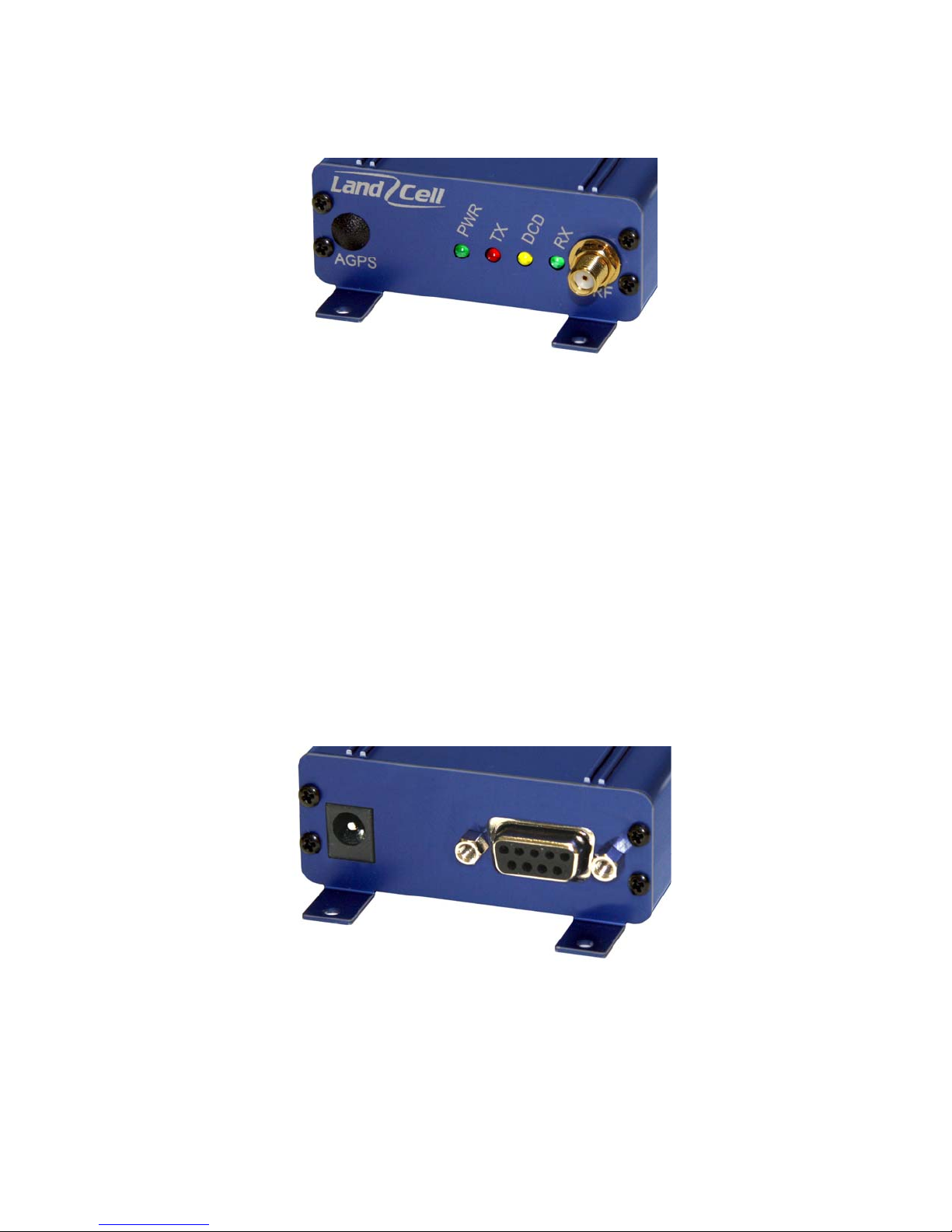
Front panel connections
819-1XRT front panel indicators include:
PWR: Green LED indicating power to unit.
Tx: Red LED indicating Transmit activity.
DCD: Amber LED indicating Data Carrier Detect from cellular network.
Rx: Green LED indicating Receive activity.
RF: SMA female, primary antenna connection.
AGPS: SMA female, optional AGPS antenna connection.
Back panel connections
Fig. 2.1 819-1XRT Front Panel
819-1XRT back panel connections include:
Power connector: 2.1mm x 5.5mm DC Barrel Jack (Center Positive)
RS-232 port: Standard DE-9 female
Fig. 2.2 819-1XRT Back Panel
001-0003-819 Rev 1
Page 8 of 48
Page 9
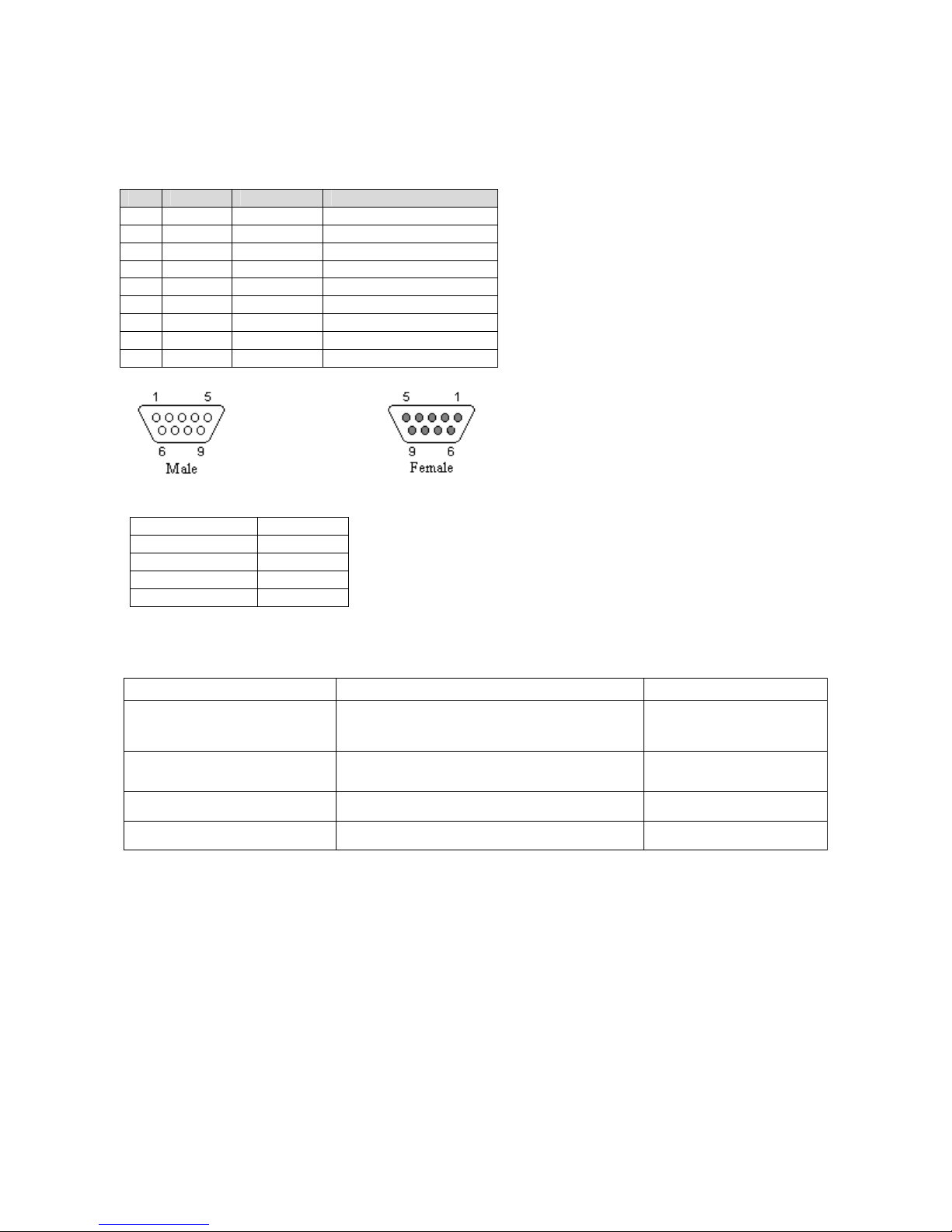
RS-232 Serial Port Integration Parameters
Table 2.1 provides the serial cable design information to integrate the 819-1XRT into your
system.
Table 2.1 Standard RS-232 DE-9 Pin out
Pin Name Direction Description
1 CD «— Carrier Detect
2 RX «— Receive Data
3 TX —» Transmit Data
4 DTR —» Data Terminal Ready
5 GND System Ground
6 DSR «— Data Set Ready
7 RTS —» Request to Send
8 CTS «— Clear to Send
9 RI «— Ring Indicator
Note: Direction is DTE relative DCE.
Table 2.2 Default RS-232 Communication Parameters
Bits Per Second 115,200
Data Bits 8
Parity None
Stop Bits 1
Flow Control None
Accessories & Options
Accessory/Option Description Order Number
Antenna
Power Supply
4” Rubber Duck Antenna
3” Mag Mount Antenna
110 VAC input
DC Power Cable
L2-ANT0001
L2-ANT0003
L2-PWR0001
L2-PWR0002
Interface Cable Serial Cable L2-CAB0002
AGPS Option Installed AGPS antenna connector 823-7500-501
Primary Antenna
The primary and optional AGPS antenna connections on the 819-1XRT are female connectors.
Purchase antennas with SMA male connectors. Do not select an SMA antenna with “reverse
polarity” or RP-Male. When using a direct mount or “rubber duck” antenna, choose the antenna
specific to your band requirements. Mounting options and cable lengths are user’s choice and
application specific.
001-0003-819 Rev 1
Page 9 of 48
Page 10
SSEECCTTIIOONN 44 –– GGEETTTTIINNGG SSTTAARRTTEEDD
Package Contents
• 819-1XRT cellular data modem (specific to CDMA cellular provider)
• Information card
Setting up the 819-1XRT Modem using the CDMA 819S Driver:
You may download the necessary modem driver files from our website at http://www.calamp.com. If
you are installing the modem using the drivers from the website, refer to these steps:
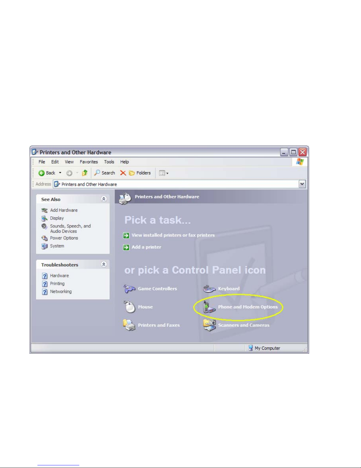
1. Click on Start --> Settings --> Control Panel. Select "Phone and Modem Opti ons".
001-0003-819 Rev 1
Page 10 of 48
Page 11
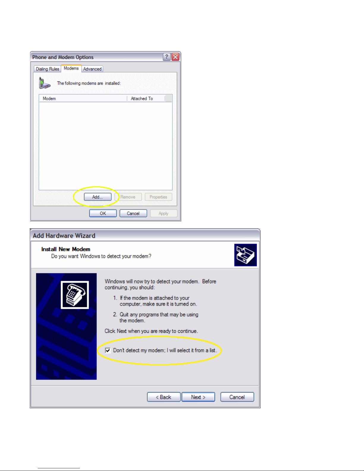
2. Select the “Modem” tab. Select “Add...” and complete the Wizard. Check “Don’t D e tect My
Modem”.
001-0003-819 Rev 1
Page 11 of 48
Page 12

3. Select "Have Disk…" Click “Next”.
4. Browse to the file location where the CDMA 819S modem driver was downloaded.
001-0003-819 Rev 1
Page 12 of 48
Page 13
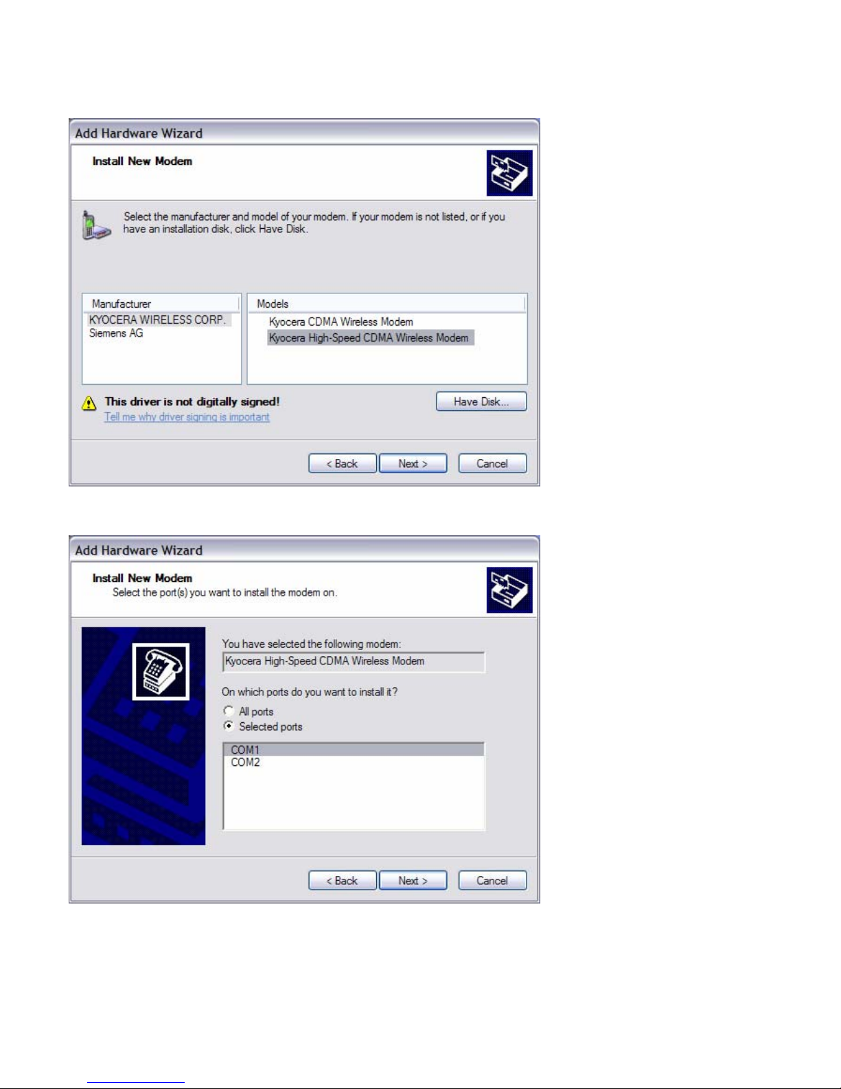
5. Select the KYOCERA WIRELES S CORP. manufacturer and Kyocera High-Speed CDMA
Wireless Modem model. Click “Next”.
6. Assign the modem to the COM port connected to the modem. Click “Next”.
7. Click “Finish”.
001-0003-819 Rev 1
Page 13 of 48
Page 14
Setting up the CDM-819S using native Windows drivers:
1. Click on Start --> Settings --> Control Panel. Select "Phone and Modem Opti ons".
2. Select the “Modem” tab. Select “Add.” Complete the Wizard. Check “Don’t Detect My Modem ”.
3. Select "Standard 19200 bps Modem." Click “Next”.
4. Assign the modem to the COM port connected to the modem. Click “Next”.
5. Click “Finish”.
Configuring the Modem
1. Click on Start --> Settings --> Control Panel. Select "Phone and Modem Options".
2. Click “New” or “Edit” to add or modify a location name.
3. In "Location Name", enter a name to distinguish this connection as the 819-1XRT modem. Type
your area code in the Area Code box.
4. Click "Apply" and “OK”. The window should exit out to the Phone and Modem Options box.
5. Click the tab at the top titled "Modems". Select the "Kyocera High-Speed Modem" (or the
"Standard 19200 bps Modem" if you’re using the native Windows driver) and click "Properties".
6. Click the "Modem" tab at the top of this new box. The box titled "Maximum Port Speed" should
read: 115200. If not, scroll down to select 115200. Click “OK”. Click "Apply".
7. Click “OK”.
Creating a Dial-Up Networking (DUN) connection
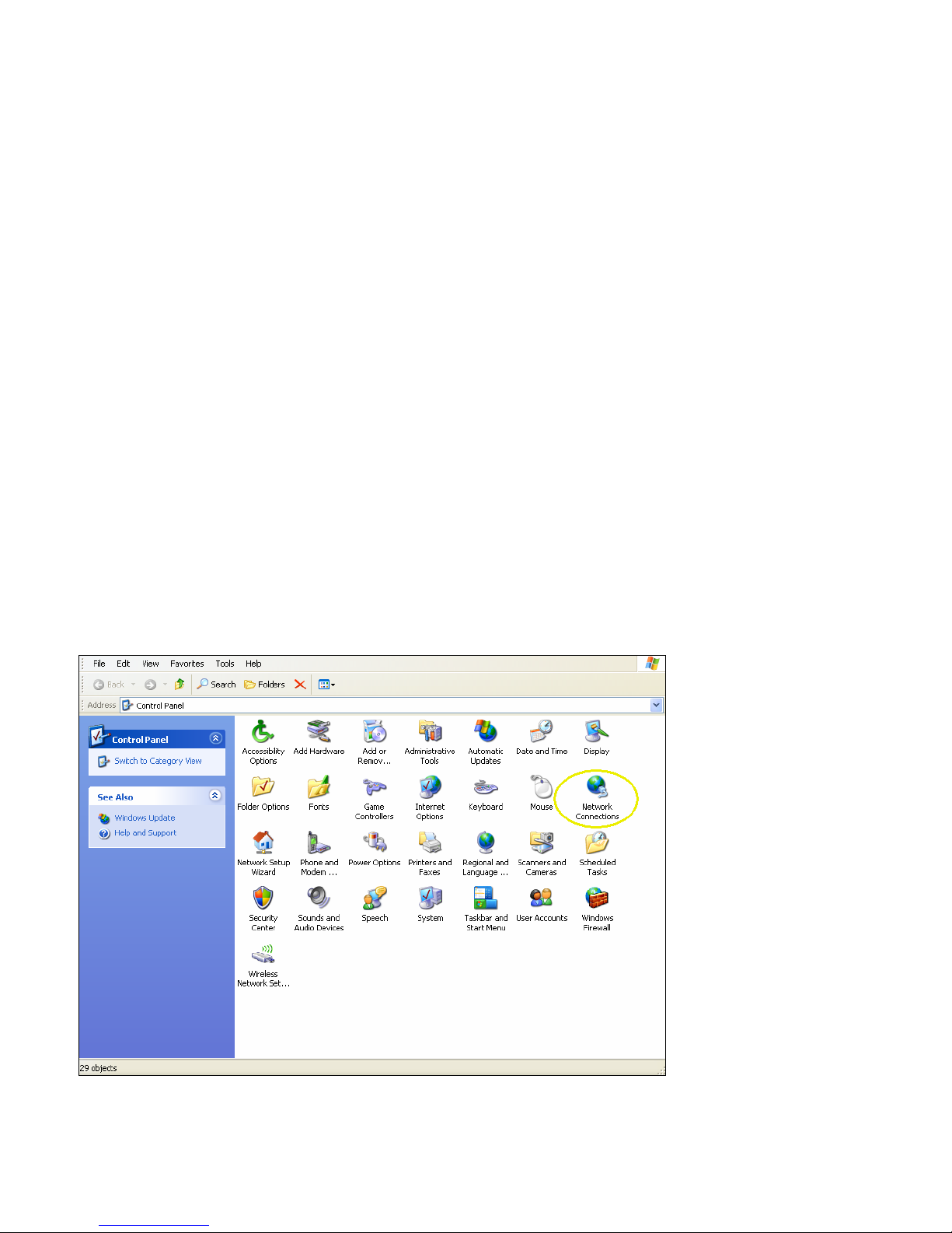
1. Click on Start --> Settings --> Control Panel. Select "Network Connections".
001-0003-819 Rev 1
Page 14 of 48
Page 15
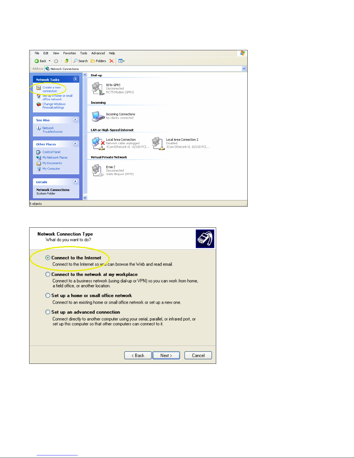
2. From the Network Connections screen, select “Create a new connection”. Follow the Wizard as it
goes through the steps to create a dial-up connection by selecting “Next”.
3. For the connection type, select “Connect to the Internet”. Click “Next”.
001-0003-819 Rev 1
Page 15 of 48
Page 16

4. Select “Set up my connection manually”. Click “Next”.
5. For the Internet connection, select “Connect using a dial-up modem”. Click “Next”.
001-0003-819 Rev 1
Page 16 of 48
Page 17

6. Check the box by the modem for the CDMA device. Click “Next”.
7. Type in a connection name. Click “Next”.
001-0003-819 Rev 1
Page 17 of 48
Page 18

8. Type in #777 for the phone number to dial. This is the number for 1xRTT packet data calls.
9. Typically the username and password are left blank. Click “Next”.
10. Click “Finish” in the Wizard. The network connection should now be available on the Network
Connections screen.
To verify the DUN connection is configured properly, go to the Network Connections screen and
double click on the Dial-up connection for the 819-1XRT CDMA modem. The Connect 819s CDMA
connection screen will appear. Selecting Dial would initiate the Dial Up Connection. To check the
settings, select Properties.
001-0003-819 Rev 1
Page 18 of 48
Page 19

From the Properties window, confirm the correct modem driver is checked under “Connect using:”
and select Configure.
001-0003-819 Rev 1
Page 19 of 48
Page 20

In the Configuration window, confirm the maximum speed (bps) is set to 115200, as shown in the
Modem Configuration Screen. Click OK to exit out of each screen.
Refer to Packet Data Call Setup in Section 5 for further information on call setup procedures.
001-0003-819 Rev 1
Page 20 of 48
Page 21

Operational States
The modem has three operational states:
• Command State
• Online State
• Online Command State
When first powered on, the modem is in the Command State where it is able to accept AT
commands. When instructed to dial out or to answer a data call, the phone is in the Online State.
Activating your Modem
1. Connect the modem to an active COM port on a PC with an RS-232 9 pin straight through cable.
2. Attach the antenna and power connector.
3. Connect with a Hyper-Terminal session set to 115,200, 8 Bits, No Parity, 1 Stop Bit, and
Hardware Flow Control enabled. Refer to Figure 4.1.
Figure 4.1: 819-1XRT HyperTerminal Port Settings
4. Confirm contact with the modem with the AT+GSN command. This prints the ESN of the modem
i.e. (+GSN: 45262036). If you get an Error or no communication, verify the modem is connected
to the proper COM port and powered on. Refer to Figure 4.2.
5. Verify good signal strength with the AT+CSQ? command. A typical reply is +CSQ? 13,99. Signal
strength ranges from 0 to 31 (minimum number for activating should be > 6).
001-0003-819 Rev 1
Page 21 of 48
Page 22

6. Confirm your registration on the cellular network with the AT+CSS? command. A reply of +CSS?
2,Z,99999 indicates the modem is not registered on the network. It may take up to 15 seconds
after power-up to register on the network. Once registered, a typical response is +CSS?:
1,A,4152 where 1 is the band class, 1=800 MHz, 2=1900 MHz, A-F is the band (Z indicates the
modem is not registered on the network), 4152 is the SID, i.e. the cell tower ID, (99999
indicates the modem is not registered on the network).
7. Verify the phone number currently in the modem with the AT$KWDIR? command. It should be
10 digits (i.e. 0000005555) prior to activation.
8. Perform the activation instructions specific to your carrier as indicated in Section 6 - Carrier
Specific Information (i.e., for Verizon, OTASP can be initiated with an AT command of
AT+CDV*22899). Wait 2 minutes.
9. After the unit has been activated, confirm programming success by verifying the assigned
number with the AT$KWDIR? command. It should now display your assigned number.
10. You can also confirm the assigned PRL number with the AT+GMR command. Power cycle the
modem. If your account supports voice, modem activation can be confirmed by performing a
voice call to your cell phone with the AT+CDV<Cell Phone Number> command (without spaces
or angle brackets). Your cell phone should ring and display the phone number of the modem.
Figure 4.2: 819-1XRT HyperTerminal Modem Activation
Configuration and test of a Circuit Switch Data (CSD) call, and Packet Data Call (TCP/IP) are
discussed in the next section.
001-0003-819 Rev 1
Page 22 of 48
Page 23

SSEECCTTIIOONN 55 –– 881199--11XXRRTT FFAASSTT--TTRRAACCKK CCAALLLL SSEETTUUPP GGUUIIDDEESS
Circuit Switch Data (CSD) Call Setup
1. Connect the modem to an active COM port on a PC with an RS-232 9 pin straight through cable.
2. Attach the antenna and power connector.
3. Connect with a Hyper-Terminal session set to 115,200, 8 Bits, No Parity, 1 Stop Bit, and
Hardware Flow Control enabled (the default speed of the modem).
4. If the modem has not been activated, activate the modem. See Sections 4 and 6 for information
specific to your carrier.
5. Change the baud rate to your required speed, i.e. 9600. AT+IPR=9600. Disconnect
HyperTerminal, change the baud rate to 9600 and reconnect.
6. Confirm contact with modem using AT+GSN - this prints out the ESN of the modem (i.e. +GSN:
45263AF4). If you get an error or no communication, go to Section 7 on Troubleshooting.
7. To auto-answer calls set ATS0=1 A value of ATS0=1 sets the modem to answer on the first
ring, where ATS0=0 disables the auto-answer feature. (NOTE: this is a letter S followed by a
Zero)
8. Set the modem to answer/terminate incoming asynchronous data calls; AT$QCVAD=4
9. To set the Carrier Detect (DCD) to follow its connection state to the Cellular Network, set
AT&C1. The yellow DCD LED will turn on when connected to the carrier, and turn off when not
connected. A value of AT&C0 sets CD to always on, and a value of AT&C2 sets CD to be always
on, but to wink when there is a change in the connection state.
10. Ensure that DTR is set to return to modem to command state on an ON-to-OFF transition of DTR
with AT&D2. A value of AT&D0 ignores DTR, a value of AT&D1 enters online command state
upon an ON-to-OFF transition of DTR.
11. Save the new settings in Profile 1 with AT&W1 and then set Profile 1 as the Default profile with
AT&Y1 (Please note an ATZ will do perform a soft reset of the modem with profile 0
settings. Power cycling or doing an ATZ1 will restore the modem using profile 1
settings. Beware of ATZ commands in your init strings.)
12. To confirm your settings, perform an AT&V. This will print out about 7 lines of text with the
register values.
13. Verify good signal strength with AT+CSQ?. A typical reply is +CSQ? 19,99
. Signal strength
ranges from 0 to 31, the higher the number the stronger the signal.
14. Set the modem for verbose result codes, with ATV1, this displays result codes as words, ATV0
displays result codes as digits.
15. Confirm you are registered on the cellular network with AT+CSS? A reply of +CSS? 2,Z,99999
indicates you are not registered. It may take up to 15 seconds after power-up to register on the
network. Once registered, a typical response will be +CSS?: 1,A,4152 where 1 is the band
class, 1=800 MHz, 2=1900 MHz, A-F is the band (Z indicates not registered on network), 4152 is
the SID, i.e. the cell tower ID, (99999 indicates you are not registered on network).
16. Test CSD Origination by calling your cell phone with ATDT<phone number> (for example,
5551234567). Once the phone rings and you answer the phone, you should hear sounds similar
to a fax negotiation.
17. Test CSD Termination by calling the phone number of your modem. Once it answers you should
hear sounds similar to a fax negotiation. Hang up to terminate the connection.
001-0003-819 Rev 1
Page 23 of 48
Page 24

18. To further test CSD termination, connect another modem, (landline or cellular) to an available
COM port on a PC. Configure that modem and the COM port to your required speed, i.e. 9600,
with AT+IPR=9600.
19. Start HyperTerminal on the PC’s COM port and call the LandCell modem from this terminal
window with the following command. ATDT<phone number of 819 Modem>.
20. The terminal window connected to the 819-1XRT modem, will say “RING”. Once the modems
have negotiated a connection, it will say “CONNECT”.
21. You can now type in text in either terminal window and it will appear in the other terminal
window. This verifies your modem is now answering incoming CSD data calls.
22. Type in ATH0 to disconnect the call.
23. Once you can originate and terminate CSD calls with the modem, you are ready to connect the
modem to your equipment. Please ensure your equipment is configured to your required data
rate, i.e. 9600 bps.
24. By default, the modem is configured for full hardware flow control. This uses CTS and DTS, DSR
and DTR, Carrier Detect, and Ring Indicator control signals. The pin-out of the modem is in
Section 2.
25. If you are using a 3 wire interface cable with RX, TX and Ground or your equipment is configured
for no hardware flow control, you will need to disable Hardware flow control with AT+IFC=0,0
and save it in your profile with AT&W1.
26. If your equipment cannot disable hardware flow control, you can spoof the signals by shorting
pins 1, 4, and 6 together, and also pins 7 and 8 on the DE-9 connectors of your three-wire cable.
Packet Data Call Setup
1. Create a 19,200 Generic Modem or, use the Network Connection created in Section 4 using the
CDMA 819S Driver, and configure it for 115,200, 8 bits, no parity, 1 stop bit. Attach the modem
to an active COM port on the PC (i.e., COM1).
2. Configure the selected COM port to a maximum speed of 115,200 in the Hardware device
manager.
3. Attach the antenna and power to the 819-1XRT modem.
4. Connect it to the COM port with a 9 pin RS-232 straight through serial cable.
5. If the modem has not been activated, activate the modem. See Sections 4 and 6 for information
specific to your carrier.
6. Use HyperTerminal on the COM port to set Carrier Detect (DCD) to follow its connection state to
the Cellular Network, set AT&C1. The yellow LED will turn on when connected to the carrier, and
turn off when not connected. A value of AT&C0 sets CD to always on, and a value of AT&C2
sets CD to always on but to wink when there is a change in the connection state.
7. Ensure DTR is set to return the modem to command state with an ON-to-OFF transition of DTR
using AT&D2. A value of AT&D0 ignores DTR. A value of AT&D1 enters the online command
state upon an ON-to-OFF transition of DTR.
8. Save the new settings in Profile 1 with AT&W1. Set Profile 1 as the Default profile with AT&Y1
(note: an ATZ will perform a soft reset of the modem with profile 0 settings. Power cycling or
doing an ATZ1 will restore the modem using profile 1 settings. Beware of ATZ commands in
your init strings.)
9. To confirm your settings, perform an AT&V. This will print approximately 7 lines of text with the
register values.
001-0003-819 Rev 1
Page 24 of 48
Page 25

10. Confirm you are registered on the cellular network with AT+CSS? A reply of +CSS? 2,Z,99999
indicates you are not registered. It may take up to 15 seconds after power-up to register on the
network. Once registered a typical response will be +CSS?:1,A,4152 where 1 is the band class,
1=800 MHz, 2=1900 MHz, A-F is the band (Z indicates not registered on network), 4152 is the
SID, i.e. the cell tower ID, (99999 indicates not registered on network).
11. Exit HyperTerminal.
12. Create a Dial-Up Networking (DUN) connection using the modem you created with the active
COM port (i.e., COM1) in Network and Dial-up Connections. Configure it to 115,200 bps and set
security to Typical.
13. Start a DUN session by double clicking on the DUN icon.
14. Set the username and password as defined for your carrier.
15. Enter the phone number as #777 with no area code and click on Dial.
16. The modem will dial out and attempt to connect.
17. If the configured baud rate for the modem, the COM port, the modem and the DUN do not
match, the DUN will not talk to the modem properly and you w ill get a hardware error message.
Otherwise the DUN will contact the cellular network and authenticate the user on the network.
18. Once connected, you can browse the Internet through the DUN session. To confirm this, disable
any other network connection you may have running.
001-0003-819 Rev 1
Page 25 of 48
Page 26

SSEECCTTIIOONN 66 –– CCAARRRRIIEERR SSPPEECCIIFFIICC IINNFFOORRMMAATTIIOONN
Verizon Wireless Subscribers
For Verizon Wireless subscribers residing in the United States, the standard provisioning
procedure is by issuing the command AT+CDV*22899. If the modem will not provision and you
have verified the serial number is activated in the Verizon system, manually key in the ph one
number. In cellular terminology, the phone number is known as the Mobile Directory Number
(MDN). The MDN is the number you call to connect to the modem and is entered following the
steps below. Enter these commands via your terminal emulation software:
• AT+GMR (Note the PRL Number)
• AT$KWMODE=1
• AT$KWSPC=000000
• AT$KWDIR=10-Digit MDN phone number from Verizon (without hyphens)
• AT$KWMSID=10-Digit (MIN) number from cellular carrier (without hyphens). This on ly
needs to be entered if different than the MDN.
• AT$KWMODE=2
• AT+CDV*22899
After issuing the last command, let the modem sit uninterrupted for four minutes. After four
minutes, remove the power supply jack from the modem. Re-insert it several seconds later.
Reconnect via terminal emulation and query the unit with these commands:
• AT$KWMODE? (returns online mode)
• AT$KWDIR? (returns modem’s phone number)
• AT+GMR (returns firmware version and PRL)
If the PRL is different than before, OTASP has definitely occurred.
Call your phone to test activation. When it rings, confirm the number, answer and hang-up to
disconnect the call. (Do not enter the angle brackets, just the cell phone number without
spaces.)
• AT+CDV<Phone Number>
001-0003-819 Rev 1
Page 26 of 48
Page 27

Sprint PCS Subscribers
Sprint PCS uses IOTA (IP-based Over The Air) for their over-the-air provisioning system. IOTA
uses packet data calls to transfer configuration data to the phone. These IOTA data sessions can
be network or client initiated. Network initiat ed IOTA is the preferred method.
An automatic network initiated IOTA session occurs when the module first registers onto the
Sprint network. This IOTA session is queued when Sprint originally sets up and 'activates' the
account. In their current implementation, Sprint imposes a 72 hour expiration timer for this
queued IOTA session.
An IOTA session has a device time out of 15 minutes. If there is no success within 15 minutes,
the status will change to fail and the module will stop trying. A normal IOTA session takes from 1
to 3 minutes. To register onto the network, the module needs a sufficient signal and must have
been manually provisioned with the MDN and MSID.
The IOTA session will occur and populate the 3GPD paramet ers. If it is the first IOTA session, it is
called a Network Initiated Initial Provisioning (NIIP.)
NOTE: An IOTA session MUST occur while the device has a sufficient signal and is registered on
the Sprint PCS Network. A session will not be successful if the device is out of coverage or not
properly registered on the Sprint PCS network.
Use the following commands to program the modem.
• AT$KWMODE=1
• AT$KWSPC=Unlock/Activation Code (6 or 7 digits supplied by Sprint)
• AT$KWDIR=10-Digit (MDN) directory phone number from Cellular Carrier (without hyphens)
• AT$KWMSID=10-Digit (MIN) number from cellular carrier (without hyphens). This on ly
needs to be entered if different than the MDN.
• AT$KWMODE=2
Power off the modem for 15 seconds. Power on the modem. Wait 5 to 10 minutes to register on
the network.
Call your phone to test activation. When it rings, confirm the number matches, answer and hangup to disconnect the call. (Do not enter the angle brackets, just the cell phone number without
spaces.)
• AT+CDV<Phone Number>
001-0003-819 Rev 1
Page 27 of 48
Page 28

Alltel Subscribers
Alltel uses both OTAPA and a manual process for provisioning modems. The OTAPA process is for
voice phones and is not normally possible with a modem. The manual process must be followed.
The ESN is entered into their database and an MDN and MIN number are assigned to the
account. The MDN is the number used to contact the modem and the MIN is an internal number
used for cellular network routing. Most of the time, these numbers are the same. It is very
important to program these numbers correctly. If numbers are reversed, the modem will not
work correctly. The MIN is automatically loaded with the MDN number. The MDN must be entered
first.
• AT$KWMODE=1
• AT$KWSPC=000000
• AT$KWDIR=10-Digit (MDN) directory phone number from cellular carrier (without hyphens)
• AT$KWMSID=10-Digit (MIN) number from cellular carrier (without hyphens) This only
needs to be entered if different than the MDN.
• AT$KWMODE=2
Call your phone to test activation. When it rings, confirm the number matches, answer and hangup to disconnect the call. (Do not enter the angle brackets, just the cell phone number without
spaces.)
• AT+CDV<Phone Number>
001-0003-819 Rev 1
Page 28 of 48
Page 29

Telus (Canada) Subscribers
The standard procedure to provision the modem is by issuing the command AT+CDV*22803. If
the modem will not provision and you have verified the serial number is activated with Telus,
manually key in the phone number. In cellular terminology, the phone number is known as the
Mobile Directory Number (MDN). The MDN is the number called to connect to the modem and is
entered following the steps below. Enter these commands via your terminal emulation software:
• AT+GMR (Note the PRL Number)
• AT$KWMODE=1
• AT$KWSPC=000000
• AT$KWDIR=10-digit MDN phone number from Telus (without hyphens)
• AT$KWMSID=10-digit (MSID/MIN) number from cellular carrier (without hyphens). This
only needs to be entered if different than the MDN
• AT$KWMODE=2
• AT+CDV*22803
After issuing the last command, let the modem sit uninterrupted for four minutes. After four
minutes, remove the power supply jack from the modem. Re-insert it several seconds later.
Reconnect via terminal emulation and query the unit with these commands:
• AT$KWMODE? (returns online mode)
• AT$KWDIR? (returns modem’s phone number)
• AT+GMR (returns firmware version and PRL)
If the PRL is different than before, OTASP has definitely occurred.
Call your phone to test activation. When it rings, confirm the number matches, answer and hang-
up to disconnect the call. (Do not enter the angle brackets, just the cell phone number without
spaces.)
• AT+CDV<Phone Number>
001-0003-819 Rev 1
Page 29 of 48
Page 30

SSEECCTTIIOONN 77 –– TTRROOUUBBLLEESSHHOOOOTTIINNGG
This section provides important information relating to the setup and diagnosis of your 819-1XRT
modem. If you are having trouble communicating with the modem, please read this
"Troubleshooting" section in full. If, after reviewing this section, you are still having problems
connecting, call our Technical Support line at: 507-833-8819 for more assistance. Toll charges may
apply.
Helpful Hints
Only assign one device to any given COM port on your system.
The 819-1XRT data modem has a default COM port speed of 115,200 bps. This is the data rate at
which your modem connects to your computer. The modem's COM port speed can be lowered to 300
bps or raised to 230,400 bps. Warning: Please ensure your COM port is capable of 230,400 data
rates before changing the modem to this speed. As this setting adjusts the communications speed
the modem utilizes to speak to the computer, specific steps must be performed to alt er this
parameter. Otherwise, you may lose communication with the modem. To alter the default speed of
115,200 bps:
• Connect via your terminal emulation software (settings: 115200bps, 8, N, 1, Hardware)
• Issue the AT+IPR command to query or change the default speed
• After adjusting the port speed, disconnect from the modem and reconnect using the new data
rate
Refer to the "Extended AT Configurations Command Table" in Section 10 for more information
pertaining to the AT+IPR command.
Confirm the serial cable is firmly connected to an enabled COM port and the COM port is without
hardware resource conflicts. Verify set up of the added "Kyocera High-Speed Modem" (or "Standard
19200 bps Modem") to your system (see Section 4 above). Also, check to see if you have an infrared
(IR) port assigned to your modem's COM port. Disable it if you are not using this function. Often, an
IR port can interfere with the COM port even after you successfully connect. Your Devi ce Manager
may indicate no conflict between the two, but disabling the IR port may help.
If your system's COM port appears to be locked, shut down and reboot your system.
Do not use "Disable Call Waiting" (commonly referred to as *70) when configuring Dialing
Properties.
Confirm you are using the correct RS-232 serial cable. For most applications, you must use a
straight-through RS-232 serial cable. For certain types of equipment, you may be required to use a
null modem cable.
Diagnosing COM Port Problems Using HyperTerminal
If you are experiencing problems connecting to the cellular network, you can verify whether the
issue is between the computer and the modem or between the modem and the cellular network. To
test, open your terminal emulation software (i.e., Hyperterminal.) Once the modem is ready to
accept commands, type: AT+GSN and press enter. The ESN of the modem should print out on the
screen in the following format “+GSN: 45262036”. This will confirm communications with the
LandCell modem and not another device connected to or inside the PC. If the ESN does not print out,
confirm you have correctly selected the COM port the modem is attached to, and not another port
(internal modems typically show up as COM3.)
001-0003-819 Rev 1
Page 30 of 48
Page 31

To test the link between your modem and the cellular network, try to call your cell phone. Type in:
AT+CDV<phone number to call> (without spaces and angle brackets) and press enter. This
command will perform a voice call similar to the type a standard home phone would make. If your
modem has been activated correctly, your cell phone should ring and display the number of the
modem. Answer the incoming call on your cell phone and hang-up. If you are properly
communicating with the modem using the steps above and still cannot connect through the cellular
network, check these items:
• Call the phone number of the modem. If the phone number is not active, the cellular service
will alert user
• Confirm the ESN on the label match es the ESN in the module with AT+GSN. This will print out
the ESN of the modem in Hex format, +GSN: 45263F2A. If the numbers do not match, the
wrong ESN may be in your account
• Contact your cellular provider and make certain the Electronic Serial Number (ESN) of the
modem is active in their system
• Check signal strength using the following command: AT+CSQ? A typical reply is +CSQ?
19,99. Signal strength ranges from 0 to 31, the higher the number the stronger the signal.
(see also the FAQ for more information on "No Carrier" issues)
• Issue the command: AT+CSS? to verify the modem is registered onto a cell tower. If the
return from the modem is: 2,Z,99999, the modem is not registered. It may take up to 15
seconds after power-up to register on the network. Once registered, a typical response will be
+CSS?: 1,A,4152 where 1 is the band class, 1=800 MHz, 2=1900 MHz,A-F is the band (Z
indicates not registered on network), 4152 is the SID, i.e. the cell tower ID, (99999 indicates
not registered on network)
• Attempt to relocate the modem and/or antenna to receive a stronger signal
• Verify the modem has been provisioned by the cellular network. To provision the modem, see
the Appendix for activation instructions for your carrier
NOTE: Running diagnostics from Modem Properties may fail if the computer attempts to
communicate with the modem at an incorrect baud rate.
Altering The Modem’s Cellular Parameters
If you have subscribed to a cellular provider using the serial number printed on the modem case and
have confirmed the ESN matches with an AT+GSN command but still cannot provision the unit,
program the Mobile Directory Number (MDN), the IMSI number (if different than the MDN), Mo bi le
Country Code (MCC) and/or the Mobile Network Code (MNC).
after all other steps fail. The next six sub-sections explain how to change these parameters.
Entering Offline Digital Mode
To change the MDN, MSID, MCC or the MNC, first change the operational mode to Offline Digital by
typing: AT$KWMODE=1
After changing this (or any other) parameter, you may query the modem, by typing a "?" in place of
the "=". For example, to confirm you are in the Offline Digita l Operational Mode, you would type:
AT$KWMODE?
Only change the MCC and MNC if
001-0003-819 Rev 1
Page 31 of 48
Page 32

Unlocking The Service Programming Code (SPC)
As a safety precaution, to keep unauthorized users from gaining access to the device, the modem
carries a Service Programming Code (SPC). The default SPC is 000000. Without entering this code,
you cannot alter the modem's configuration. To unlock the modem and allow write access, enter the
SPC with this command: AT$KWSPC=000000
Entering The Mobile Directory Number (MDN)
The MDN is the phone number used to call the modem from other devices. Enter the MDN given to
you by your CDMA provider by typing: AT$KWDIR=<number provided by CDMA provider>
Entering The MSID/MIN Number
The MSID/MIN is the last 10 digits of the IMSI_M internal number assigned by the carrier for
network routing. Enter the MSID given to you by your CDMA provider by typing:
AT$KWMSID=<number provided by CDMA provider>
Entering The Mobile Country Code (MCC)
It is only necessary to enter the Mobile Country Co de (MCC) and Mobile Network Code (MNC) if the
modem is not already programmed for operation in your area. If required, these codes are available
from your CDMA provider. To change the MCC type: AT$KWMCC=<3 digit MCC>
Entering The Mobile Network Code (MNC)
To alter the MNC, type: AT$KWMNC=<2 digit MNC>
After configuring your modem, issue the command: AT$KWMODE=2
This resets the modem and writes your configuration changes to non-volatile memory. Your
modem is now programmed for operation in the area. These configuration ch anges will remain
even if the modem loses power. Once the modem is properly configured, activate the modem as
described in Section 4.
001-0003-819 Rev 1
Page 32 of 48
Page 33

SSEECCTTIIOONN 88 –– UUSSEERR PPRROOFFIILLEESS
There are 3 user profiles; two profiles are editable. The third profile contains the factory default
settings. All user-configurable parameters which can be saved may be stored into a profile with the
&Wn command, listed below where n is profile 1 or 2. Note: saving to a profile does not activate that
profile. To utilize the new saved settings on the next power-cycle of the modem, you must instruct
the modem to use the profile of your choice with the command &Yn.
NOTE: Profile 0 is the Reference Profile and cannot be changed. Only Profile 1 and 2 can be changed.
Table 8.1: User Profile Commands
&Vn
&Wn
Displays configuration of profile n (where n = 0, 1, 2). Issuing &V by itself
without a profile designator will display th e current configuration settings
Saves the current AT configuration settings to the user profile designated by
n (where n = 1, 2)
Sets profile n (where n = 0, 1, 2) as the default profile on the next boot. If
&Yn
no value for &Y has been set, the modem will load all parameters from profile
0 as default profile
Soft resets the modem and loads AT parameters out of profile n (where n =
&KWZn
0, 1, 2). For parameters not included in profile n, the modem will load factory
default settings
ATZ Will reset the modem using Profile 0 settings
ATZn Will reset the modem using Profile n (0,1,2) settings
001-0003-819 Rev 1
Page 33 of 48
Page 34

SSEECCTTIIOONN 99 –– CCOOMMMMOONN AATT CCOOMMMMAANNDD RREEFFEERREENNCCEE GGUUIIDDEE
Commonly used AT commands in day-to-day modem operation
Entering Access Codes:
To retrieve the Serial Number of the modem (in hexadecimal format): AT+GSN
To perform Over-the-Air Service Provisioning (OTASP): AT+CDV*22899
To change to Offline Digital mode: AT$KWMODE=1
To enter the SPC and unlock the modem for programming: AT$KWSPC=000000
To enter the Mobile Identification Number (MIN): AT$KWDIR=<MIN>
To write configuration changes and reset the modem, type: AT$KWMODE=2
Communication Parameters:
To check the baud rate: AT+IPR?
To change the baud rate: AT+IPR=<baud rate>
Valid baud rates: 300, 600, 1200, 2400, 4800, 9600, 14400, 19200, 38400, 57600, 115200 bps.
To change the flow control: AT+IFC=2,2 (The values are: 0: No Flow Control, 1: Xon/Xoff, 2:
Hardware)
Query Analog Or Digital Service: AT+CAD? returns:
0: No service is available
1: CDMA digital service is available
2: TDMA digital service is available
3: Analog service is available
To check the signal strength: AT+CSQ? returns <Signal Quality>,<Frame Error Rate>
Signal Quality <SQM>:
0-31: Signal Quality Measurement
99: SQM is not known or is not detectable.
Frame Error Rate <FER>:
0: <0.01%
1: 0.01% to less than 0.1%
2: 0.1% to less than 0.5%
3: 0.5% to less than 1.0%
4: 1.0% to less than 2.0%
5: 2% to less than 4.0%
6: 4% to less than 8.0%
7: >=8.0%
99: FER is not known or is not detectable.
To Set Up For Inbound/Outbound Calls:
To set up the modem for auto-answer: ATS0=1
To enable incoming connections for async calls: AT$QCVAD=4
To enable automatic packet call connections: AT$QCPKND=0
To disable automatic packet call connections: AT$QCPKND=1
Answer Incoming Voice Call: AT$QCCAV
Hangs up the modem: ATH
Hang up voice call: AT+CHV0
Set auto-answer to 15 seconds after the first ring: ATS0=3
Sets if the modem originates a call upon reception of an unknown command: AT+CXT
Dial a cellular voice call: AT+CDV<phone number to call>
To make a circuit-switched connection: ATDT<phone number to call>
Disconnect and return to command state: ATH
001-0003-819 Rev 1
Page 34 of 48
Page 35

Miscellaneous Commands:
Echo commands in command state or in online state: ATE1
Do not echo commands in command state or in online state: ATE0
Display result codes as numbers: ATV0
Display result codes as words: ATV1
Dump configuration parameters: AT&V
Return to Online State from Command State: ATO
Reset to default configuration: ATZ
AT commands Digit/Word Cross Reference:
Digit Word
0 OK
1 CONNECT
2 RING
3 NO CARRIER
4 ERROR
6 NO DIAL TONE
7 BUSY
8 NO ANSWER
001-0003-819 Rev 1
Page 35 of 48
Page 36

SSEECCTTIIOONN 1100 –– AATT CCOOMMMMAANNDD RREEFFEERREENNCCEE
All modem functions are controlled using the same industry-standard AT commands used to control
landline modems. A knowledge of these commands is not required but are provided as a reference.
AT Command Types
There are five types of AT commands;
• Basic AT Parameters
• S-Registers
• Basic Action Commands
• Extended AT Configuration Commands
• Cellular AT Commands
The parameters set by the various AT commands in this section are applied to all subsequent calls
and will be used each time you place a call. As such, your custom settings (if not saved in a profile)
will be available until you power down the modem. These settings are lost upon power down
if not saved.
The 819-1XRT also gives you automatic support of all AT commands unknown to the modem but
supported by your cellular carrier’s IWF. Since the carrier may charge you for airtime used for this
connection, the modem's auto-connect ability is disabled by default. Issue the: AT+CXT=1
command to enable this mode, if needed.
Command Line Syntax
A command line consists of the attention code followed by one or more commands and terminated
by an end of line code. The attention code is the character pair "AT" or "at". By default, the end of
line character is the ASCII CR character (decimal 13), unless it is changed by the S3 command. The
ASCII CR character is equivalent to one keystroke of the ENTER key. Refer to "S-Registers" - Section
10 for more information on this command. Spaces are ignored (unless within quotes) and may be
inserted between arguments within the AT command line to make it more legible, if desired.
Basic and S-Register commands may follow each other on the command line without any separating
delimiters. The Extended Format Commands (those beginning with a "+" character) must be
terminated with a semicolon ";" if they are followed by anoth er command on the same line. The ";"
character is not required after the last command on the line.
Commands may be edited using the backspace key, but the backspace will not delete th e AT
attention command at the beginning of the command line.
Result Codes
After issuing a command, a result code will typically be displayed on the screen to inf orm you if the
command was successful, unsuccessful, improperly formatted, etc. Eight possible result codes may
be returned in the command mode. Result codes can be set to display as either digits or words by
accessing the Verbose command. The digit code is returned when the Verbose mode is OFF (V0); the
word code is returned when Verbose is ON (V1). Extended result codes may also be returned. The
result codes are listed in the Table 10.1.
001-0003-819 Rev 1
Page 36 of 48
Page 37

Table 10.1: Result Codes
Digit Verbose Description
0 OK Command executed without errors
1 CONNECT Connected to remote modem
2 RING Incoming Call
3 NO CARRIER Carrier from remote modem lost or never present
4 ERROR Error in the command line
6 NO DIAL No dial tone detected within time out period
7 BUSY Busy signal detected
8 NO ANSWER
Basic AT Parameters
Basic AT commands control the basic configuration of the modem. The parameters can only be read
back by the AT&V command when in command state. Table 10.2 shows the command format.
Parameter Description
E0 Do not echo commands in command state or in online state
E1 Echo commands in command state or in online state
I Displays the product name
I2 Displays the product name and firmware revision number.
Q0 Return result codes
Q1 Do not return result codes
V0 Display result codes as numbers
V1 Display result codes as words
X0
X1
Enable additional result code CONNECT. Disable dial tone and busy
detection
Enable additional result code CONNECT <rate>. Disable dial tone and busy
detection
Z Reset modem NV memory and reboot
&C0 Carrier Detect (CD) always ON
&C1 CD on/off in accordance with the network connection status
&C2 CD always on; Winks on channel disconnect
&D0 Ignore Data Terminal Ready (DTR)
&D1 Enter Online Command state following ON-t o-OFF transition of DTR
&D2 Enter Command state following ON-to-OFF transition of DTR
&F Reset all modem parameters to default
&V Dump current configuration parameters
&Vn Dump current configuration parameters of profile n
&Wn Saves settings to persistent storage
S-Registers
The value of an S-Register may be set by the following command line syntax:
where n is the register number and xxx is a decimal value. For instance, to set the register S0 to 3,
the command ATS0=3 would be used. Table 10.3 describes some of the more commonly used SRegisters.
Five seconds of silence not detected after ring back when @ dial
modifier is used
Table 10.2: Basic AT Parameters
ATSn=xxx
001-0003-819 Rev 1
Page 37 of 48
Page 38

Table 10.3: S-Registers
Register Value Description
S0 0 to 255
S3 13 Carriage return character. Default is 13
S4 10 Line feed character. Default is 10
S5 8 Backspace character. Default is 8
S6 2 to 10 Length of time in seconds to pause before dialing. Default is 2
S7 1 to 255
S8 0 to 255
S9 0 to 255
S10 1 to 254
S11 50 to 255 DTMF tone duration and spacing in milliseconds. Default is 95
Basic Action Commands
Table 10.4 describes the Basic Action Commands:
Command Description
A Go off hook. Answer any incoming call.
Dial. The dial string may contain the following characters:
Digits 0 to 9, *, #, A, B, C and D
The dial string may contain the following dial modifiers:
, Pause during dialing
D<dial string>
W Wait for dial tone
@ Wait for quiet answer
! Hook flash
$ Wait for billing tone
; After dialing, the phone remains in command state
H Disconnect and return to command state
O Return to online data state from command state
Extended Commands
Extended commands use extended syntax. To set a value using an extended command, use the
WRITE command:
+CMD=xxx where CMD is the command and xxx is the value.
Some extended commands take more than one value. For example, the Write command for two
values becomes:
+CMD=xxx,yyy
Some extended commands take characters strings as values, instead of numbers. In that case, the
syntax is:
+CMD="CharacterString"
Automatic answering. Number of rings before answering.
Disable automatic answering=0. Default is 0
Sets the length of time in seconds the modem waits for a carrier
before hanging up. Default is 50
Number of seconds to pause when a comma "," is encountered
in the dial string. Default is 2
Carrier detect threshold. The length of time in tenths of a
second a signal is detected and qualified as a carrier. Default is
6
Number of tenths of a second from carrier loss to disconnect.
Default is 14. Disable carrier detect=255
Table 10.4: Basic Action Commands
001-0003-819 Rev 1
Page 38 of 48
Page 39

Note: while spaces are ignored everywhere else, spaces are significant inside the quotation marks.
To read back a value, use the READ command:
+CMD?
To test if a particular command is supported, along with the range of values it supports, use the
TEST command:
+CMD=?
An extended command must be terminated with a semicolon if another command follows it in the
same command line. Table 10.5 describes the extended AT configuration commands.
Table 10.5: Extended AT Configuration Commands
Command Description
TE2-MT2 Local Flow Control.
This extended-format compound parameter is used to control the
operation of local flow control between the TE2 and the MT2. The format
is:
AT+IFC=<DCE_by_DTE>,<DTE_by_DCE>
Where:
<DCE_by_DTE> Specifies the method to be used by the DTE to control the
flow of received data from the DCE
+IFC
+IPR
+ICF
<DTE_by_DCE> Specifies the method to be used by the DCE to control
the flow of transmitted data from the DTE
The valid numeric variables for the +IFC command are as follows:
0 No Flow Control
1 Xon/Xoff
2 Hardware
By default, the modem is set up as AT+IFC=2,2 to allow hardware flow
control in both directions
Fixed Rm Rate.
This numeric extended-format parameter specifies the data rate at which
the MT2 will accept commands, in addition to 1200 bps or 9600 bps (as
required in EIA/TIA-602). It may be used to select operation at rates at
which the MT2 is not capable of automatically detecting the data rate
being used by the TE2. Rm default rates set at 115.2Kbps
Local RS-232 Interface Character Framing.
This parameter determines the character framing used at the local RS-232
interface. The syntax is: AT+ICF=<format>,<parity>
Where:
<format> is a single digit and determines the number of data bits, the
presence of a parity bit, and the number of stop bits in the start-stop
frame according to the following values:
<format> Meaning
1 8 Data, 2 Stop
2 8 Data, 1 Parity, 1 Stop
3 8 Data, 1 Stop
<parity> is a single digit and determines how the parity bit is generated
and checked, if present, according to the following values:
<parity> Meaning
0 Odd
1 Even
001-0003-819 Rev 1
Page 39 of 48
Page 40

The <parity> argument is only valid when <format> is set to 2. The
default
settings for the modem are AT+ICF=3,1.
Cellular CDMA Commands
Cellular CDMA commands use the same syntax as other extended commands. Numeric values are
decimal. Table 10.6 describes cellular CDMA commands.
Table 10.6: CDMA AT Parameter Commands
Command Description
Query Analog Or Digital Service.
Returns:
0: If service is not
+CAD?
+CSS?
+CSQ?
+CDR
available
1: If CDMA digital service is available
2: If TDMA digital service is available
3: If analog service is available
Values 4-255 are reserved
Serving System
Read Only. Returns <AB>, <SID>
AB:
A: The mobile station is registered with an A-band system
B: The mobile station is registered with a B-band system
Z: The mobile station is not registered
SID:
0-16383: The mobile station is registered with the system indicated.
99999: The mobile station is not registered
Query Received Signal Quality.
Returns the Signal Quality and Frame Error Rate as follows:
Signal Quality Measure <SQM>:
0-31: Signal Quality Measurement (See note 1 below)
99: SQM is not known or is not detectable.
All other values are reserved
Frame Error Rate <FER>:
0: <0.01%
1: > 0.01% and < 0.1%
2: > 0.1% and < 0.5%
3: > 0.5% and < 1.0%
4: > 1.0% and < 2.0%
5: > 2.0% and < 4.0%
6: > 4.0% and < 8.0%
7: >= 8.0%
99: FER is not known or is not detectable
All other values are reserved.
Note 1: The exact meaning of the Signal Quality Measure <SQM> shall be
manufacturer defined. The lowest quality reported by SQM shall be defined
as value: 00. The highest quality reported by SQM shall be defined as value:
31
Um Interface Data Compression Reporting
This extended-format numeric parameter controls whether the extendedformat +CDR intermediate result code is transmitted by the MT2
001-0003-819 Rev 1
Page 40 of 48
Page 41

Um Interface Data Compression
+CDS
+CFG
+CRC
+CXT
+CTA
+CRM
+CQD
+CFC
+DR
+DS
This extended-format compound parameter controls the V.42bis data
compression function on the Um interface
Configuration String
The string (up to and including the termination character) will be st ored by
the MT2 and sent to the base station prior to dialing. Each transmission of a
+CFG command from the TE2 replaces the contents of the previous string.
The string may be up to 248 characters
Cellular Result Codes
0: Disable cellular result codes
1: Enable cellular result codes
Cellular Extension
0: Do not pass unrecognized commands to the IWF
1: When detecting an unrecognized AT command, open transport layer
connection and pass unrecognized command to the IW
Set/Read/Test Um Packet Data Inactivity (Dormancy) Timer
0: Traffic channel not released during inactivity periods.
1-255: Release the traffic channel after <value> seconds intervals has
elapsed since the last sending or receiving RLP data frames on the Um
interface.
20: (default value)
NOTE: If the carrier has configured a +CTA value in the cellular network,
then the mobile’s value may be overridden by the network value
Set Rm Interface Protocol
0: Asynchronous Data or Fax
1: Packet data service, relay layer Rm interface
2: Packet data service, network layer Rm interface, PPP
3: Packet data service, network layer Rm interface, SLIP
4: STU-III service
5-127: Reserved for future use
128-255: Reserved for manufacturer-specific use
Note: the default value for the +CRM parameter shall be 0 if this value is
supported by the MT2. If 0 is not supported, the default +CRM value shall
be manufacturer-specific
Command Status Inactivity Timer
0: Ignored
1-255: Release call after 5 x <value> seconds have elapsed without
activity. The default <value> shall be 10, corresponding to 50 seconds
Um Interface Fax Compression
0: No compression.
1: V.42bis compression with parameters as set by the +CDS command
2: modified the modified read compression
Data Compression Reporting
This extended-format numeric parameter controls whether the extendedformat +DR intermediate result is transmitted from the IWF over the Um
interface
Data Compression.
This extended-format compound parameter controls the V.42bis data
compression function on the PSTN link if provided in the IWF
001-0003-819 Rev 1
Page 41 of 48
Page 42

Break Handling In Error Control Operation.
+EB
+EFCS
+ER
+ES
+ESR
+ETMB
+ILPP
+MA
+MR
+MS
+MV18R
+MV18S
This extended-format compound parameter is used to control the manner of
V.42 operation on the PSTN link (if present in the IWF)
Frame Check Sequence
This extended-format numeric parameter controls the use of the 32-bit
frame check sequence option in V.42 on the PSTN link (if present in the
IWF)
Error Control Reporting.
This extended-format numeric parameter controls whether the extendedformat +ER intermediate result code is transmitted from the IWF over the
Um interface
Error Control Selection.
This extended-format compound parameter is used to control the manner of
operation of the V.42 protocol on the PSTN link (if present in the IWF)
This extended-format numeric parameter controls the use of the selective
repeat (SREJ) option in V.42 on the PSTN link (if present in the IWF)
This extended-format compound parameter controls the handling of data
remaining in IWF buffers upon service termination
TE2-MT2 local rate reporting.
This extended-format numeric parameter controls whether the extendedformat +ILPP:<rate> information text is transmitted from the MT2 to the
TE2
Modulation Automode Control.
This extended-format compound parameter is a list of modulations that the
base station may use to connect with the remote DCE in automode
operation, for answering or originating data calls, as additional alternatives
to the modulation specified in the +MS command
Modulation Reporting Control.
This extended-format numeric parameter controls whether the extendedformat +MCR:<carrier> and +MRR:<rate> intermediate result codes are
transmitted from the IWF to the mobile station
Modulation Selection.
This extended-format compound parameter is used to control the manner of
operation of the modulation capabilities in the IWF
V.18 Reporting Control.
This extended-format numeric parameter controls whether the extendedformat +MV18R result code is transmitted from the IWF to the mobile
station
V.18 Selection.
This extended-format compound parameter is used to control the manner of
operation of the V.18 capabilities (if present in the IWF)
001-0003-819 Rev 1
Page 42 of 48
Page 43

Cellular AT Command extensions in support of voice services commands allow the data terminal to
be used as an automatic dialer for voice calls. The format of these commands is shown in Table
10.7.
Table 10.7: Cellular AT Command Extensions in Support of Voice Services
Command Description
+CHV<value> Hang Up Voice
0: Hang up voice call
1-255: Reserved
+CDV<dial string> Dial Command For Voice Calls
The format of <dial string> is identical to that for the ATD command.
This command does not cause the MT2 to change to the online state.
001-0003-819 Rev 1
Page 43 of 48
Page 44

SSEECCTTIIOONN 1111 –– SSPPEECCIIFFIICCAATTIIOONNSS
Product specifications are subject to change without notice.
General Specifications
Interface Connectors: RS-232 DE-9S Connector (DCE)
Power Connector: 2.1mm/5.5mm DC Barrel Jack (Center Positive)
LED Indicators: Power, Tx, DCD, Rx
Antenna Interface: SMA female
Size: 4.10 x 2.61 x 1.10 in.
Weight: 7.0 oz.
Power Input: 9.0 – 28VDC 1.2 W; 100 ma @ 12 VDC (Idle - average)
9.0 – 28VDC 3.3 W; 275 ma @ 12 VDC (Active - peak)
Maximum TX Power: CDMA: +23.5 dBm min. / +22.5 dBm min (1900MHz)
Rx Sensitivity: CDMA: >-104 dBm
Frequencies: Cellular: TX: 824-849 MHz Rx: 869-894 MHz
PCS: TX: 1850-1910 MHz Rx: 1930-1990 MHz
Temperature: Operating: -30°C to +60°C (-22° to 140°F) 100% Duty Cycle
Storage: -55°C to +85°C (-67° to 185°F)
Transport Protocols: Serial
Command Protocol: AT command set
Certifications: CDG 2 tested and approved
FCC ID: RD5-LCC0308
Industry Canada ID: IC: 5418A-LCC0308
FCC Part 15B
NOTE: Power consumption while transmitting is dependant on the TX power level of the cellular
module. The TX power level of the module is controlled by the cellular base st ation.
001-0003-819 Rev 1
Page 44 of 48
Page 45

Mechanical Specifications
This section provides the exterior dimensions of the 819-1XRT and the use of mounting flanges to
secure the modem to any surface (surfaces can be drilled to secure the modem). All drawings are
actual size. The drawings may be used as layout reference, but CalAmp advises a physical
comparison be made to the modem before proceeding with the mounting process.
All dimensions in inches.
001-0003-819 Rev 1
Page 45 of 48
Page 46

SSEECCTTIIOONN 1122 –– AABBBBRREEVVIIAATTIIOONNSS
Abbreviation Description
CDMA Code Division Multiple Access
CTS Clear to Send
DCD Data Carrier Detect
ESN Electronic Serial Number
EVDO Evolution Data Optimized
GPRS General Packet Radio Service
GPS Global Positioning System
IOTA Internet Over the Air
LED Light Emitting Diode
OTA Over the Air
OTASP Over the Air Service Provisioning
PPP Point to Point Protocol
PRL Preferred Roaming List
RSSI Receive Signal Strength Indication
Rx Receive
Tx Transmit
001-0003-819 Rev 1
Page 46 of 48
Page 47

SSEECCTTIIOONN 1133 –– SSEERRVVIICCEE AANNDD SSUUPPPPOORRTT
Product Warranty, RMA and Contact Information
CalAmp guarantees every 819-1XRT Cellular Modem will be free from physical defects in
material and workmanship for one (1) year from the date of purchase when used within the
limits set forth in the Specifications section of this manual.
The manufacturer's warranty statement is available in Appendix 1. If the product proves
defective during the warranty period, contact CalAmp DataCom Customer Service to obtain a
Return Material Authorization (RMA).
RMA Request
Contact Customer Service:
Dataradio dba CalAmp Wireless DataCom
299 Johnson Avenue, Suite 110
Waseca, MN 56093
Tel: 507-833-8819 ext. 6707
Fax: 507-833-6748
BE SURE TO HAVE THE EQUIPMENT MODEL, SERIAL NUMBER, AND BILLING AND SHIPPING
ADDRESSES ON HAND WHEN CALLING.
When returning a product, mark the RMA clearly on the outside of the package. Include a
complete description of the problem and the name and telephone number of a contact
person. RETURN REQUESTS WILL NOT BE PROCESSED WITHOUT THIS INFORMATION.
For units in warranty, customers are responsible for shipping charges to CalAmp Wireless
DataCom. For units returned out of warranty, customers are responsible for all shipping
charges. Return shipping instructions are the responsibility of the customer.
Product Documentation
CalAmp reserves the right to update its products, software, or documentation without
obligation to notify any individual or en tity. Product updates may result in differences
between the information provided in this manual and the product shipped. For current
product documentation, datasheets, programming software and user manuals visit
www.calamp.com.
Technical Support
M-F 7:30 AM to 4:30 PM CDT
CalAmp Wireless DataCom
299 Johnson Avenue, Suite 110
Waseca, MN 56093
Tel: 507-833-8819
E-mail: supportIMC@calamp.com
001-0003-819 Rev 1
Page 47 of 48
Page 48

AAPPPPEENNDDIIXX 11 –– WWAARRRRAANNTTYY SSTTAATTEEMMEENNTT
CalAmp DataCom warrants to the original purchaser for use ("Buyer") that data telemetry products
manufactured by DRL ("Products") are free from defects in material and workmanship and will
conform to DRL's published technical specifications for a period of, except as noted below, one (1)
year from the date of shipment to Buyer. DRL makes no warranty with respect to any equipment not
manufactured by DRL, and any such equipment shall carry the original equipment manufacturer's
warranty only. DRL further makes no warranty as to and specifically disclaims liability for,
availability, range, coverage, grade of service or operation of the repeater system provided by the
carrier or repeater operator. Any return shipping charges for third party equipment to their
respective repair facilities are chargeable and will be passed on to the Buyer.
If any Product fails to meet the warranty set forth above during the applicable warranty period and
is returned to a location designated by DRL. DRL, at its option, shall either repair or replace such
defective Product, directly or through an authorized service agent, within thirty (30) days of receipt
of same. No Products may be returned without prior authorization from DRL. Any repaired or
replaced Products shall be warranted for the remainder of the original warranty period. Buyer shall
pay all shipping charges, handling charges, fees and duties for returning defective Products to DRL
or DRL's authorized service agent. DRL will pay th e return sh ipping charges if t he Produ ct is repaired
or replaced under warranty, exclusive of fees and duties. Repair or replacement of defective
Products as set forth in this paragraph fulfills any and all warranty obligations on the part of DRL.
This warranty is void and DRL shall not be obligated to replace or repair any Products if (i) the
Product has been used in other than its normal and customary manner; (ii) the Product has been
subject to misuse, accident, neglect or damage or has been used other than with DRL approved
accessories and equipment; (iii) unauthorized alteration or repairs have been made or unapproved
parts have been used in or with the Product; or (iv) Buyer failed to notify DRL or DRL's authorized
service agent of the defect during the applicable warranty period. DRL is the final arbiter of such
claims.
THE AFORESAID WARRANTIES ARE IN LIEU OF ALL OTHER WARRANTIES, EXPRESSED AND
IMPLIED, INCLUDING BUT NOT LIMITED TO, ANY IMPLIED WARRANTY OF MERCHANTABILITY OR
FITNESS FOR A PARTICULAR PURPOSE. DRL AND BUYER AGREE THAT BUYER'S EXCLUSIVE REMEDY
FOR ANY BREACH OF ANY OF SAID WARRANTIES IT AS SET FORTH ABOVE. BUYER AGREES THAT IN
NO EVENT SHALL DRL BE LIABLE FOR INCIDENTAL, CONSEQUENTIAL, SPECIAL, INDIRECT OR
EXEMPLARY DAMAGES WHETHER ON THE BASIS OF NEGLIGENCE, STRICT LIABILITY OR
OTHERWISE. The purpose of the exclusive remedies set forth above shall be to provide Buyer with
repair or replacement of non-complying Products in the manner provided above. These exclusive
remedies shall not be deemed to have failed of their essential pu rpose so long as DRL is willing and
able to repair or replace non-complying Products in the manner set forth above.
This warranty applies to all Products sold worldwide. Some states do not allow limitations on implied
warranties so the above limitations may not be applicable. You may also have other rights, which
vary from state to state.
EXCEPTIONS
ONE YEAR: Labor to replace defective parts in repeaters or base stations
THIRTY DAY: Tuning and adjustment of telemetry radios
NO WARRANTY: Fuses, lamps and other expendable parts
Effective 1/2008
001-0003-819 Rev 1
Page 48 of 48
 Loading...