

Page 1
CalAmp reserves the rights to these documents and any information contained therein. Reproduction, use
or disclosure to third parties without express permission is strictly prohibited. ©2018 CalAmp
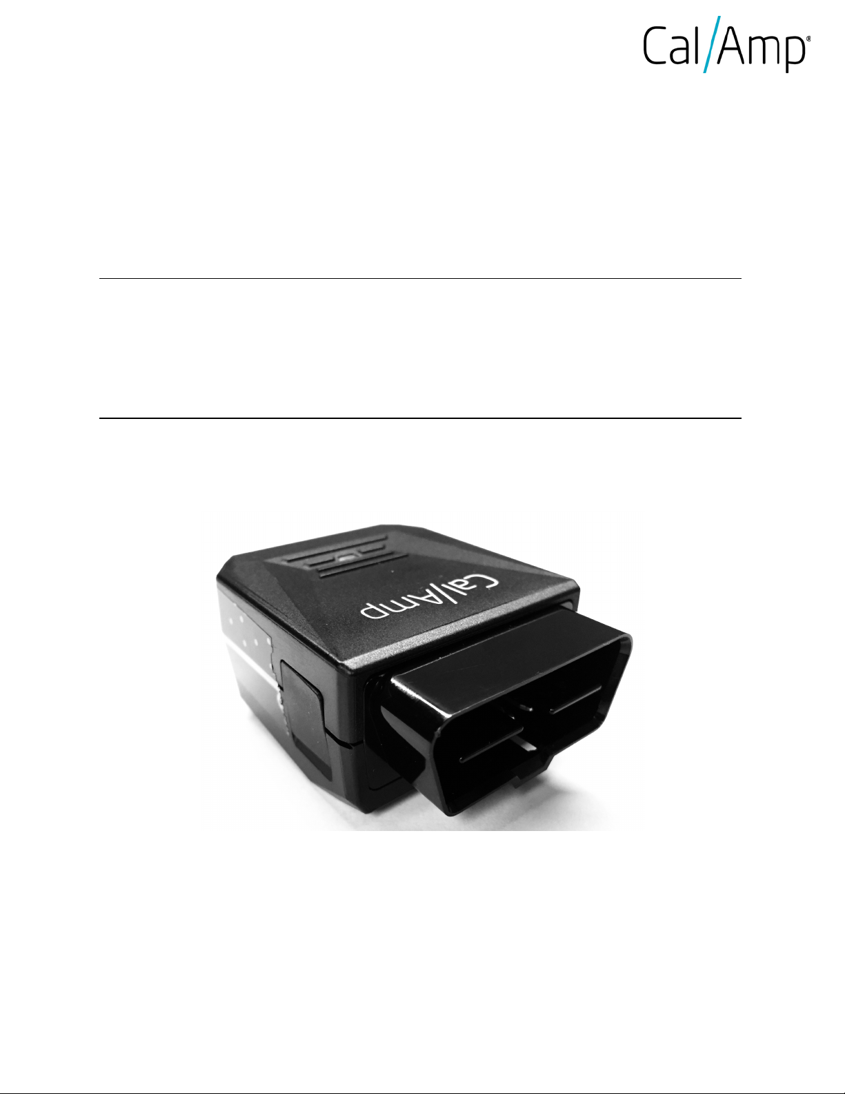
LMU-3040
C
alAmp LMU-3040 Hardware and Installation Guide – Rev. A
Page 2

LMU-3040 Hardware & Installation Guide
COMPANY CONFIDENTIAL: CalAmp reserves all rights to these documents and any information contained therein.
Page
Table of Contents
1 Introduction ............................................................................................................................................... 4
1.1 About This Manual .............................................................................................................................. 4
1.2 About The Reader ............................................................................................................................... 4
1.3 About CalAmp ..................................................................................................................................... 4
1.4 About the CalAmp Location Messaging Unit-LMU-3040™ ................................................................. 5
2 System Overview ........................................................................................................................................ 6
2.1 Overview ............................................................................................................................................. 6
2.2 Component Descriptions .................................................................................................................... 7
2.2.1 Wireless Data Network ................................................................................................................ 7
2.2.2 LMU-3040™ .................................................................................................................................. 7
2.2.3 LM Direct™ Server ........................................................................................................................ 7
2.2.4 Backend Software ........................................................................................................................ 7
2.2.5 PULS™ ........................................................................................................................................... 8
2.2.6 LMU Manager™ ............................................................................................................................ 8
2.2.7 Wireless Data Network ................................................................................................................ 8
2.2.8 LMU-3040™ .................................................................................................................................. 8
3 Hardware Overview ................................................................................................................................... 9
3.1 Location Messaging Unit-LMU-3040™ ................................................................................................ 9
3.1.1 LMU-3040™ Handling Precautions .............................................................................................. 9
3.1.2 Battery Back-up devices ............................................................................................................. 10
3.1.3 Environmental Specifications ..................................................................................................... 10
3.2 LMU-3040™ Connectors ................................................................................................................... 12
3.2.1 Primary Connector ..................................................................................................................... 12
3.2.2 Serial Adapter ............................................................................................................................. 13
3.2.3 Accessories ................................................................................................................................. 13
3.3 I/O Descriptions ................................................................................................................................ 13
3.3.1 3-Axis Accelerometer + 3-Axis Gyroscope ................................................................................. 14
3.3.2 Status LEDs ................................................................................................................................. 14
4 Installing the LMU .................................................................................................................................... 15
4.1 Preventing Accidental or Unauthorized Modification ...................................................................... 15
4.2 Installing the LMU in a vehicle .......................................................................................................... 15
Reproduction, use or disclosure to third parties without express permission is strictly prohibited. ©2018 CalAmp
2 of 31
Page 3

LMU-3040 Hardware & Installation Guide
COMPANY CONFIDENTIAL: CalAmp reserves all rights to these documents and any information contained therein.
Page
4.3 Installation Verification ..................................................................................................................... 17
4.3.1 Comm Verification ..................................................................................................................... 17
4.3.2 GPS Verification ......................................................................................................................... 18
4.3.3 Inbound Verification .................................................................................................................. 19
4.3.4 Verification via SMS ................................................................................................................... 20
5 CalAmp Locations ..................................................................................................................................... 23
6 License Agreement ................................................................................................................................... 24
7 Limited Warranty ..................................................................................................................................... 28
8 Regulatory Information ............................................................................................................................ 30
Reproduction, use or disclosure to third parties without express permission is strictly prohibited. ©2018 CalAmp
3 of 31
Page 4

LMU-3040 Hardware & Installation Guide
COMPANY CONFIDENTIAL: CalAmp reserves all rights to these documents and any information contained therein.
Page
IMPORTANT: DO NOT INSTALL OR USE THE SOFTWARE OR DOCUMENTATION UNTIL YOU HAVE
READ AND AGREED TO THE LICENSE AGREEMENT AND REVIEWED THE LIMITED
WARRANTY AND REGULATORY INFORMATION.
1 Introduction
Welcome to the LMU-3040™ Hardware and Installation Guide. This manual is intended to give you information
on the basic setup and installation of the CalAmp LMU-3040™ product(s) including hardware descriptions,
environmental specifications, wireless network overviews and device installation.
1.1 About This Manual
The LMU-3040™ is a full featured OBD vehicle tracking device that is optimized for a diverse range of
applications including driver behavior management, car rental and automotive applications. Best suited
for accessing the vehicle diagnostics interface (OBD-II) in passenger or light-duty vehicles.
accurately describe the functionality of these units we have broken this manual into the following sections:
System Overview – A basic description of a CalAmp LMU-3040™ based tracking system. This
includes a description of roles and responsibilities of each of the CalAmp components as well as a
In order to
brief overview of the wireless data technologies used by the LMU-3040™.
Hardware Overview – Describes the physical characteristics and interfaces of the LMU-3040™.
Installation and Verification – Provides guidance for the installation of the LMU-3040™ in a
vehicle and instructions on how to verify the installation is performing adequately.
1.2 About The Reader
In order to limit the size and scope of this manual, the following assumptions have been made about the
reader.
You are familiar with GPS concepts and terminology
You have some experience with installing equipment in vehicles
You are familiar with the use of AT Commands
You are familiar with the use of terminal programs such as HyperTerminal or PuTTY
1.3 About CalAmp
CalAmp is a leading provider of wireless communications products that enable anytime/anywhere access to
critical information, data and entertainment content. With comprehensive capabilities ranging from product
design and development through volume production, CalAmp delivers cost-effective high quality solutions to a
broad array of customers and end markets. CalAmp is the leading supplier of Direct Broadcast Satellite (DBS)
outdoor customer premise equipment to the U.S. satellite television market. The Company also provides
Reproduction, use or disclosure to third parties without express permission is strictly prohibited. ©2018 CalAmp
4 of 31
Page 5

LMU-3040 Hardware & Installation Guide
COMPANY CONFIDENTIAL: CalAmp reserves all rights to these documents and any information contained therein.
Page
wireless data communication solutions for the telemetry and asset tracking markets, private wireless networks,
public safety communications and critical infrastructure and process control applications. For additional
information, please visit the Company’s website at www.calamp.com.
1.4 About the CalAmp Location Messaging Unit-LMU-3040™
The CalAmp Location and Messaging Unit-LMU-3040™ (LMU-3040™) is a mobile device that resides in
private, commercial or government vehicles. The LMU-3040™ is a single box enclosure incorporating a
processor, a GPS receiver, a wireless data modem, and a vehicle-rated power supply. The LMU-3040™ also
supports inputs and outputs to monitor and react to the vehicular environment and/or driver actions.
Flexibility
The LMU-3040™ features CalAmp's industry leading advanced on-board alert engine that monitors vehicle
conditions giving you the most flexible tracking device in its class. The next generation PEG-
2™ (Programmable Event Generator 2) script engine application supports hundreds of customized exception-
based rules to help meet customers' dynamic requirements. Customers can modify the behavior of the device
to meet with a range of applications preprogrammed before shipment or in the field. Combining affordability and
device intelligence with your unique application can give you distinct advantages over your competition.
Seamlessly convert previous generation PEG script and upgrade to a more efficient, cost effective and robust
platform, while greatly reducing maintenance efforts.
Over-the-Air Serviceability
The LMU-3040™ also incorporates CalAmp's industry leading over-the-air device management and
maintenance system software, PULS™ (Programming, Updates, and Logistics System). Configuration
parameters, PEG-2 rules, and firmware can all be updated over the air. Our web-based maintenance server,
PULS™ scripts, and firmware, can all be updated over-the-air. PULS™ offers out-of-the-box hands free
configuration and automatic post-installation upgrades. You can also monitor unit health status across your
customers' fleets to quickly identify issues before they become expensive problems.
Reproduction, use or disclosure to third parties without express permission is strictly prohibited. ©2018 CalAmp
5 of 31
Page 6
LMU-3040 Hardware & Installation Guide
COMPANY CONFIDENTIAL: CalAmp reserves all rights to these documents and any information contained therein.
Page
2 System Overview
2.1 Overview
The entire purpose behind a fleet management system is to be able to remotely contact a vehicle, determine its
location or status, and do something meaningful with that information. This could include displaying the vehicle
location on a map, performing an address look-up, providing real-time driving directions, updating the vehicles
ETA, monitoring vehicle and driver status or dispatching the vehicle to its next pick up.
These functions, of course, are completely dependent on the capabilities of the vehicle management
application. The role of the CalAmp LMU-3040™ is to deliver the location information when and where it is
needed.
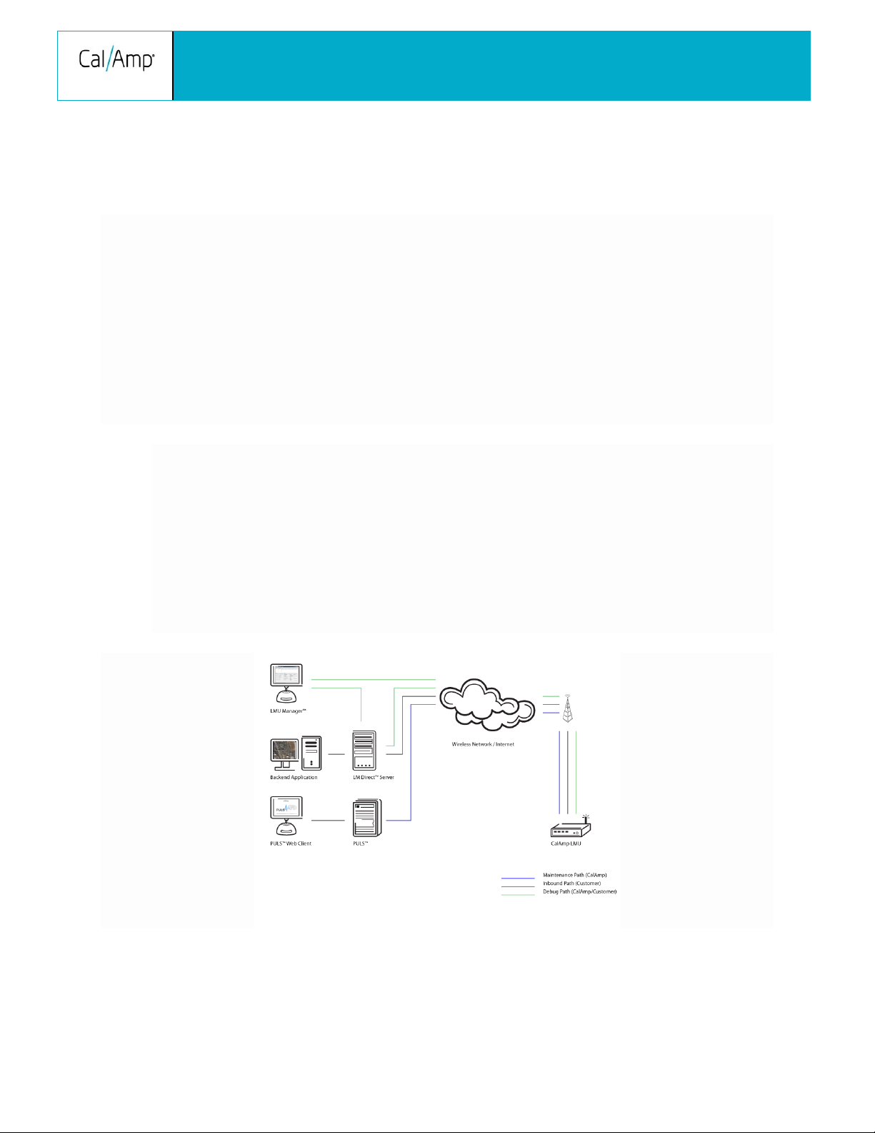
A typical fleet management system based on a CalAmp device includes the following components:
A wireless data network
An LMU-3040™
Host Device An LM Direct™ communications server
Backend mapping and reporting software which typically includes mapping and fleet reporting
functions
PULS™
LMU Manager™
Reproduction, use or disclosure to third parties without express permission is strictly prohibited. ©2018 CalAmp
6 of 31
Page 7

LMU-3040 Hardware & Installation Guide
COMPANY CONFIDENTIAL: CalAmp reserves all rights to these documents and any information contained therein.
Page
2.2 Component Descriptions
2.2.1 Wireless Data Network
The Wireless Data Network provides the information bridge between the LM Direct™ server and the LMU3040™. Wireless data networks can take a variety of forms, such as cellular networks, satellite systems or local
area networks. Contact the CalAmp sales team for the networks available to the LMU-3040™.
2.2.2 LMU-3040™
The LMU-3040™ is responsible for delivering the location and status information when and where it is needed.
Data requests mainly come from the following sources:
PEG-2™ script within the LMU-3040™
A location or status request from the LM Direct™ server
A location or status request from LMU Manager
An SMS request made from a mobile device such as a customer’s cell-phone
In some cases, it is necessary to run an application in the vehicle while it is being tracked by the backend
software. Such examples could include instant messaging between vehicles or a central office, in-vehicle
mapping or driving directions, email or database access. In most of these cases you will be using the LMU3040™ as a wireless modem as well as a vehicle-location device.
2.2.3 LM Direct™ Server
LM Direct™ is a CalAmp proprietary message interface specification detailing the various messages and their
contents the LMU-3040™ is capable of sending and receiving. This interface allows System Integrators to
communicate directly with LMU-3040's™. Please refer to the LM Direct Reference Guide for details.
2.2.4 Backend Software
Backend software is a customer provided software application. Regardless of its purpose, one of its primary
functions is to parse and present data obtained from the LM Direct™ server. This allows the application to do
any of the following:
Display location database on reports received from the LMU-3040™ in a variety of formats
Present historic information received from the LMU-3040™, typically in a report/chart style format
Request location updates from one or more LMU-3040s™
Update and change the configuration of one or more LMU-3040s™
Reproduction, use or disclosure to third parties without express permission is strictly prohibited. ©2018 CalAmp
7 of 31
Page 8

LMU-3040 Hardware & Installation Guide
COMPANY CONFIDENTIAL: CalAmp reserves all rights to these documents and any information contained therein.
Page
2.2.5 PULS™
PULS™ (Programming, Update and Logistics System) is CalAmp’s web-based maintenance server offering
out-of-the-box hands free configuration and automatic post-installation upgrades. PULS™ provides a means for
configuration parameters, PEG scripts, and firmware to be updated Over-The-Air (OTA) and allows CalAmp
customers to monitor unit health status across your customers’ fleets to quickly identify issues before they
become expensive problems.
2.2.6 LMU Manager™
LMU Manager is the primary configuration tool in the CalAmp system. It allows access to almost every feature
available to the LMU-3040™. Unlike the backend software, it has the option of talking directly to an LMU3040™ or making a request forwarded by the LM Direct™ server.
For further details on using LMU Manager, please refer to the LMU Manager Users Guide.
2.2.7 Wireless Data Network
The Wireless Data Network provides the information bridge between the LM Direct server and the LMU3040™s. Wireless data networks can take a variety of forms, such as cellular networks, satellite systems or
local area networks. At this point in time, the networks available to the LMU-3040™ are:
LTE (Long-Term Evolution)
Long-term evolution (LTE) is the latest and rapidly growing global data transmission technology. Based
on GSM and UMTS/HSPA standards, LTE is a standard of high-speed wireless data transmission and
communication. Continuously evolving, LTE advancements continue to push data capacity and user
experience on a global scale. With a peak downlink rate of 300 mbps, uplink rate of 75 mbps, LTE sits
in 1.4 MHz to 20 MHz bands, while also supporting FDD, TDD, and not sacrificing data capability.
2.2.8 LMU-3040™
The LMU-3040™ is responsible for delivering the location and status information when and where it is needed.
Data requests can come from any of the following sources:
PEG-2™ script within the LMU-3040™
A location or status request from the LM Direct server
A location or status request from LMU Manager
A request made from a host device such as a laptop, PDA or MDT
Reproduction, use or disclosure to third parties without express permission is strictly prohibited. ©2018 CalAmp
8 of 31
Page 9

LMU-3040 Hardware & Installation Guide
COMPANY CONFIDENTIAL: CalAmp reserves all rights to these documents and any information contained therein.
Page
3 Hardware Overview
3.1 Location Messaging Unit-LMU-3040™
3.1.1 LMU-3040™ Handling Precautions
Electrostatic Discharge (ESD)
Electrostatic discharge (ESD) is the sudden and momentary electric current that flows between two objects at
different electrical potentials caused by direct contact or induced by an electrostatic field. The term is usually
used in the electronics and other industries to describe momentary unwanted currents that may cause damage
to electronic equipment.
ESD Handling Precautions
ESD prevention is based on establishing an Electrostatic Protective Area (EPA). The EPA can be a small
working station or a large manufacturing area. The main principle of an EPA is that there are no highly charging
materials in the vicinity of ESD sensitive electronics, all conductive materials are grounded, workers are
grounded, and charge build-up on ESD sensitive electronics is prevented. International standards are used to
define typical EPA and can be obtained for example from International Electro-technical Commission (IEC) or
American National Standards Institute (ANSI).
This ESD classification of the sub assembly will be defined for the most sensitive component, therefore the
following classifications apply:
Class 1B – Human Model (< 1 kV)
Class M1 – Machine Model (< 100V)
When handling the LMU-3040’s™ main-board (i.e. sub assembly) by itself or in a partial housing proper ESD
precautions should be taken. The handler should be in an ESD safe area and be properly grounded.
GPS Ceramic Patch Handling
When handling the sub assembly it may be natural to pick it up by sides and make contact with the antenna
boards. In an uncontrolled ESD environment contact with the center pin of ceramic patch antenna can create a
path for electrostatic discharge directly to the GPS Module. The GPS Module is very sensitive to ESD and can
be damaged and rendered non-functional at low levels of ESD. One should avoid contact with the center pin of
the patch during handling.
Packaging
Anytime the sub assembly is shipped and it is not fully packaged in its final housing it must be sealed in an
ESD safe bag.
Electrical Over-Stress (EOS)
Reproduction, use or disclosure to third parties without express permission is strictly prohibited. ©2018 CalAmp
9 of 31
Page 10

LMU-3040 Hardware & Installation Guide
COMPANY CONFIDENTIAL: CalAmp reserves all rights to these documents and any information contained therein.
Page
The GPS receiver can be damaged if exposed to an RF level that exceeds its maximum input rating. Such
exposure can happen if a nearby source transmits an RF signal at sufficiently high level to cause damage.
Storage and Shipping
One potential source of EOS is proximity of one LMU-3040™ GPS Antenna to another LMU-3040™ GSM
Antenna. Should one of the units be in a transmit mode the potential exists for the other unit to become
damaged. Therefore any LMU-3040™ GPS Antenna should be kept at least four inches apart from any active
LMU-3040™ GSM Antenna or any other active high power RF transmitter with power greater than 1 Watt.
3.1.2 Battery Back-up devices
Please properly dispose of the battery in any of the CalAmp products that utilize one, do not just throw used
batteries, replaced batteries, or units containing a back-up battery into the trash. Consult your local waste
management facility for proper disposal instructions
3.1.3 Environmental Specifications
The LMU-3040™ is designed to operate in environments typically encountered by fleet vehicles, including wide
temperature extremes, voltage transients, and potential interference from other vehicle equipment.
To ensure proper operation in such an environment, the LMU-3040™ was subjected to standard tests defined
by the Society of Automotive Engineers (SAE). The specific tests included temperature, shock, vibration, and
EMI/EMC. These tests were performed by independent labs and documented in a detailed test report. In
accordance with Appendix A of SAE J1113 Part 1, the Unit is considered a “Functional Status Class B,
Performance Region II” system that requires Threat Level 3 Testing.
The following shows the environmental conditions the LMU is designed to operate in and the relevant SAE
tests that were performed. No formal altitude tests were conducted.
Dimensions
2.49”(L) x 1.89”(W) x 1.14”(H)
63.25mm (L) x 48mm (W) x 29mm (H)
Weight
1.83oz (52g)
Operating Temperature
-30° C to 75° C
Storage Temperature
-40° C to 85° C
Reproduction, use or disclosure to third parties without express permission is strictly prohibited. ©2018 CalAmp
10 of 31
Page 11

LMU-3040 Hardware & Installation Guide
COMPANY CONFIDENTIAL: CalAmp reserves all rights to these documents and any information contained therein.
Page
Humidity
0% to 95% relative humidity, at 50° C non-condensing
Shock and Vibration
SAE Test: SAE J1455 Compliant
Mil Standard 202G and 810F Compliant
Ground vehicle environment with associated shock and vibration
Electromagnetic Compatibility (EMC/EMI)
SAE Test: SAE J1113 Parts 2, 12, 21 and 41 Compliant
FCC Part 15B, IC, CE, GCF, RoHS
EMC compliant for a ground vehicle environment
Operating Voltage Range
12/24 VDC Vehicle systems
Power Consumption
Active Standby: 140mA at 12VDC
Sleep on Network: 11mA at 12VDC
Deep Sleep: < 1 mA at 12VDC
GPS
31 channel GPS Receiver
GPS, Glonass, Beidou, Galileo
2m CEP (with SBAS)
Acquisition sensitivity: -148 dBm
-162 dBm tracking sensitivity
Communications (Comm) – Operating Bands (MHz)
North America Variant I:
4G LTE CAT-1: (Quad Band) 1900/[1700/2100]/850/700
3G UMTS/HSPA+ Fallback: (Dual Band) 850/1900
North America Variant II:
4G LTE CAT-1: (Dual Band) [1700/2100]/700
Data Support: UDP, SMS
Reproduction, use or disclosure to third parties without express permission is strictly prohibited. ©2018 CalAmp
11 of 31
Page 12

LMU-3040 Hardware & Installation Guide
COMPANY CONFIDENTIAL: CalAmp reserves all rights to these documents and any information contained therein.
Page
3.2 LMU-3040™ Connectors
3.2.1 Primary Connector
The LMU-3040 equips a 16-Pin J1962 Compliant OBD-II Plug that also supports the following OBD-II
physical layer interfaces:
1. ISO 15765 CAN
2. ISO 9141-2 K-Line
3. ISO 14230 KWP2000]
4. J1850 PWM
5. J1850 VPW
Connector on Vehicle side
Connector on LMU-3040 side
Please note that only 13 out of the 16 connector pins are actually populated on the connector.
Pin Signal Name Description
1 Make/Model Specific Vendor Option
2 Bus+ Line SAE-J1850 PWM and SAE-1850 VPW
3 Make/Model Specific Vendor Option
4 Chassis Ground Ground
5 Signal Ground Ground
Reproduction, use or disclosure to third parties without express permission is strictly prohibited. ©2018 CalAmp
12 of 31
Page 13

LMU-3040 Hardware & Installation Guide
COMPANY CONFIDENTIAL: CalAmp reserves all rights to these documents and any information contained therein.
Page
6 Can High ISO 15765-4 and SAE-J2284
7 K line ISO 9141-2 and ISO 14230-4
8 Make/Model Specific Vendor Option
10 Bus- Line SAE-J1850 PWM and SAE-1850 VPW
11 Make/Model Specific Vendor Option
14 Can Low ISO 15765-4 and SAE-J2284
15 L line ISO 9141-2 and ISO 14230-4
16 Battery Power Power
3.2.2 Serial Adapter
Depending on the variant of the LMU3040, the LMU-3040 may or may not have an external serial connector. If
it does not have a serial connector as shipped, the LMU 3040 requires additional steps in order to use a serial
connector. Please contact your FAE for steps on how to do this.
3.2.3 Accessories
See the Harness Diagrams page for more information on LMU accessories, and supported products table
3.3 I/O Descriptions
The LMU-3040™ provides the following Inputs for scripting purposes, but there are no selectable inputs
on the device
Digital Inputs
Input 0: Engine ON
Input 1: Motion Sensor (low = no motion, high = motion)
Input 2: Power State (low = main power, high = battery power)
Input 3: Vbatt Low
Input 4: Vin Active (On LMU-3040 use Input 4 for Ignition Input Wake Up Monitor instead of Input
0)
Analog to Digital Inputs
Reproduction, use or disclosure to third parties without express permission is strictly prohibited. ©2018 CalAmp
13 of 31
Page 14

COMPANY CONFIDENTIAL: CalAmp reserves all rights to these documents and any information contained therein.
Page
Accelerometer
Gyroscope
Acquisition rate: >1600Hz
Acquisition rate: >1600Hz
Sampling rate - output data rate: 100, 200, 400 Hz
Sampling rate - output data rate: 100, 200, 400 Hz
Resolution: <= 0.01G
Resolution: <= 0.01G
Full Scale: 15-24G
Full Scale: 15-24G
Outputs
LMU-3040 Hardware & Installation Guide
A/D 0: Vin
A/D 1: uP Temp
A/D 2: Vref
A/D 3: Battery
A/D 4: Impact
Output 4: Power Supply Switch (cleared = switch to external power, set = switch to internal power)
Output 5: Enable/Disable Battery charging (cleared = enable battery charging, set = disable
battery charging)
3.3.1 3-Axis Accelerometer + 3-Axis Gyroscope
The LMU-3040™ supports an internal 3 Axis Precision Accelerometer as one of its discreet inputs. When the
LMU is moved in any direction, the associated input will be in the High state. If the LMU’s accelerometer does
not detect motion, then the input will be in the Low state. No external connections are required for this
functionality to be operational.
3.3.2 Status LEDs
The LMU-3040™ contains one dual-colorstatus LEDs (amber and green). Please note that there are PEG
configuration parameters that can change the factory default behavior of all LEDs. LED behavior detail can be
reviewed in the table below:
LED Definitions and Behavior
Reproduction, use or disclosure to third parties without express permission is strictly prohibited. ©2018 CalAmp
14 of 31
Page 15

COMPANY CONFIDENTIAL: CalAmp reserves all rights to these documents and any information contained therein.
Page
Condition
Order
LED Color
LED Frequency
Power On
1
Amber/Green
Fast
GPS On
2
Green
Slow blinking
GPS Time Sync
2
Green
Fast blinking
GPS Fix
2
Green
Solid for 10 s
Comms On & Searching
3
Amber
Slow blinking
Network Available
3
Amber
Fast blinking
Registered but no inbound
acknowledgement
3
Amber
Solid & Fast Blink every 1 s
Registered and received inbound
acknowledgement
Vehicle Not Compatible
4
Amber/Green
Slow
Install Successful
5
Green
Solid
4 Installing the LMU
LMU-3040 Hardware & Installation Guide
3 Amber Solid for 10 s
4.1 Preventing Accidental or Unauthorized Modification
If you anticipate that fleet drivers or others might interfere with the LMUs once they are installed, take steps to
be sure that it is not easy to remove the LMU from its power source, etc. Two common methods are the use of
Tamper Proof Sealant or creation of PEG-2 Script to detect power loss or GPS antenna disconnections.
4.2 Installing the LMU in a vehicle
1. Make sure the vehicle is turned on/running when plugging in the unit. If the unit is plugged in while the
vehicle is off it will need to complete the detection process on the next ignition on cycle in order to operate
correctly.
2. Plug the unit into the OBD2 connector of the vehicle while it is running, and do NOT turn off the ignition.
Reproduction, use or disclosure to third parties without express permission is strictly prohibited. ©2018 CalAmp
15 of 31
Page 16

LMU-3040 Hardware & Installation Guide
COMPANY CONFIDENTIAL: CalAmp reserves all rights to these documents and any information contained therein.
Page
ATIV
!VV
-Veh Det-
3. Leave the unit plugged in with vehicle ignition on until the detection process has completed. Vehicle
detection status can be checked through SMS over the air or with AT Commands using the CalAmp serial
connection cable.
The AT Command to check vehicle detection status.
The vehicle detection complete response will look like:
-Vehicle Detection-
Detection Complete
VIN: <Vehicle Vin Number>
OBDII Protocol:5
Params:0,1,4,7,8,11,12
Indicators:0(000000000011),1(11111111111)
The SMS command to check vehicle detection status:
The vehicle detection complete response will look like:
Reproduction, use or disclosure to third parties without express permission is strictly prohibited. ©2018 CalAmp
16 of 31
Page 17

LMU-3040 Hardware & Installation Guide
COMPANY CONFIDENTIAL: CalAmp reserves all rights to these documents and any information contained therein.
Page
ATIC
Data Reg. : Yes, Home
Yes
VIN:<Vehicle Vin Number>
Proto:5
Params:0,1,4,7,8,11,12
Inds:0(000000000011),1(11111111111)
DTCs Cnt:7
Flt Mtch:1
4. Once the vehicle detection has completed the vehicle ignition can then be turned off.
4.3 Installation Verification
In many cases it is desirable to verify that an installed LMU-3040™ is working properly. That is, installers
should verify that the GPS and communications functions of the LMU-3040™ are working properly before
departing the installation site. In more robust cases, some key configuration settings such as the Inbound
Address and URL should also be verified.
Note that these processes are all based on issuing AT Commands to the LMU-3040™. It is expected that
installers will have access to a serial port expansion cable and a laptop or PDA capable of a terminal
connection. Alternatively, an SMS message can be sent to an LMU-3040™ to obtain its current status.
4.3.1 Comm Verification
Installers should first verify that the LMU-3040™ has been acquired and has registered to the wireless network.
This may be verified in one of two ways. First, installers may look at the LED. If this LED is solid, then the LMU
has registered to the network and established a data session.
If the LED is not visible, then Comm may be verified using an AT Command:
Depending on the wireless network being used something similar to what is shown below will be displayed. It is
important to verify that 'Yes' values are displayed at the top for Data and Network registration and the correct
APN is displayed.
Radio Access : LTE
Network Reg. : Yes, Home
Reproduction, use or disclosure to third parties without express permission is strictly prohibited. ©2018 CalAmp
17 of 31
Page 18

LMU-3040 Hardware & Installation Guide
COMPANY CONFIDENTIAL: CalAmp reserves all rights to these documents and any information contained therein.
Page
: routing id=0, log cid=0, modem type=21, inbnd
Connection : Yes
RSSI : -97 dBm
BER : 99
Channel : 737
Cell ID : 3441
Base Station ID : 40
Local Area Code : 31003
Network Code : 410
Country Code : 310
IMEI (Modem S/N): 351802055396182
IMSI (SIM ID) : 310410202524377
ICC-ID (SIM S/N): 89014102212025243778
Phone Number :
GPRS APN : ISP.CINGULAR
Maint. Server : maint.vehiclelocation.com(216.177.93.246):20500
Inbound Server : (0.0.0.0):20500
Dual Comm
index=0
OK
If any of the responses return Not-Acquired or Not-Registered (and the APN is correct), the wireless network
operator should be contacted for further troubleshooting.
Please note that it may take several seconds (or longer) for the LMU-3040™ to communicate with the modem
and acquire the wireless network.
4.3.2 GPS Verification
The next step is to verify that the GPS receiver is seeing enough satellites to obtain a valid GPS position.
Again, installers have two choices on how to perform this verification. First, like the Comm Verification, there is
a GPS status LED (i.e., the one closest to the SMA connector). If this LED is solid, then the LMU has found
GPS service.
If the LED is not visible then GPS service may be verified using an AT Command:
AT$APP GPS?
Reproduction, use or disclosure to third parties without express permission is strictly prohibited. ©2018 CalAmp
18 of 31
Page 19

LMU-3040 Hardware & Installation Guide
COMPANY CONFIDENTIAL: CalAmp reserves all rights to these documents and any information contained therein.
Page
RTIME HDOP=130 nSats=7
AT$APP INBOUND?
The response should be similar to:
Lat=3304713, Lon=-11727730, Alt=0
Hdg=113 Spd=0 3D-
Installers are looking for the 3D-RTIME setting along with a valid Lat, Long pair (i.e. something other than 0). If
the GPS receiver does not have a valid lock within 2-3 minutes, installers should check antenna placement
(see the Installation Notes section for placement suggestions), the antenna connector and that the antenna has
a clear view of the sky. For further troubleshooting, installers should contact CalAmp Support
(productsupport@CalAmp.com)
4.3.3 Inbound Verification
The last item to verify is that the LMU-3040™ is sending data to the correct server. In general, this is a two-step
process that will need the aid of an observer on the back end. That is, a technician will have to be logged in so
they can monitor data coming into the backend mapping/vehicle management application.
First, verify that the LMU-3040™ is using the correct Inbound IP address by using:
The response should be similar to:
INBOUND LMD
INBOUND 0 ADDR ddd.ddd.ddd.ddd:ppppp *
INBOUND 0 URL myURL.myCompany.com
INBOUND 1 ADDR 0.0.0.0:20500
INBOUND 1 URL
INBOUND 2 ADDR 0.0.0.0:20500
INBOUND 3 ADDR 0.0.0.0:20500
The installer will need to verify with a backend technician that the, URL (myURL.myCompany.com ), IP address
(ddd.ddd.ddd.ddd) and port (<ppppp>) are correct.
The second step is to verify that the LMU-3040™ is sending data. The best way to do this is to force the LMU3040™ to send in an unacknowledged Event Report (i.e., its current GPS location) with the following
command:
Reproduction, use or disclosure to third parties without express permission is strictly prohibited. ©2018 CalAmp
19 of 31
Page 20

LMU-3040 Hardware & Installation Guide
COMPANY CONFIDENTIAL: CalAmp reserves all rights to these documents and any information contained therein.
Page
AT$APP PEG SUNRPT 255
!R0
The LMU-3040™ will respond with: OK
The backend monitor must then be contacted to confirm that they received an Event Report with Event Code
255.
Assuming that all three sections have passed, the installation can be considered to be complete.
4.3.4 Verification via SMS
The current Comm, GPS and Inbound status of a LMU can be obtained via SMS provided you have access to
an SMS capable phone or PDA.
Using your handset, send the following SMS Message to the LMU:
Within a few minutes, the LMU should return a response in the following format:
APP: <App ID> <Firmware Version>
COM:<RSSI> [./d/D][./a/A][./L][IP address] [<APN>]
GPS:[Antenna <Short/Open/Off>] | [No Time Sync] | [<FixStatus> <Sat
Count>]
INP:<inputs states> <vehicle voltage>
MID:<mobile ID> <mobile ID type>
INB:<inbound IP address>:<inbound port> <Inbound Protocol (LMD/LMX)>
APP:
o <App ID>:
The Application ID value of the LMU indicating the host platform and the wireless networking technology of the
LMU.
o <Firmware Version>:
The current firmware version in use by the LMU
Reproduction, use or disclosure to third parties without express permission is strictly prohibited. ©2018 CalAmp
20 of 31
Page 21

LMU-3040 Hardware & Installation Guide
COMPANY CONFIDENTIAL: CalAmp reserves all rights to these documents and any information contained therein.
Page
COM:
o <RSSI>:
This is the signal strength the wireless modem sees from the network. In general the LMU is at least scanning
for the network if the RSSI is not -113.
o [./d/D]:
If the character ‘D’ is present, it indicates the LMU had a data session established when it responded to the
status request. For the 8-Bit product line an upper case ‘D’ indicates both the Inbound and Maintenance
sockets are ready. The lower case ‘d’ indicates that only the Maintenance socket is ready. A ‘.’ indicates no
sockets are ready.
o [./a/A]:
This field indicates if the LMU has received an Acknowledgement from the Inbound server. This field will be
empty if the LMU has never received an ACK. The lower case ‘a’ will be present if it has received an ACK since
the last cold boot (i.e. power cycle) but not the last warm boot (App Restart or Sleep). The upper case ‘A’ will
be present if the LMU has received an ACK since the last warm boot. A ‘.’ Indicates no acknowledgement has
been received.
o [./L]:
This field indicates if the LMU’s log is currently active. An ‘L’ indicates that the log is currently in use (i.e. one or
more records have been stored) where a ‘.’ indicates the log is inactive.
o [IP Address]:
This is an optional field if and is only present if the LMU has established a valid data session. This field will
contain the current IP address of the LMU as assigned by the wireless network. Note that if you see a value of
192.168.0.0, this is an indication that the LMU has not been able to establish a data session.
o [<APN>]
The current Access Point Name in use by a GSM LMU.
GPS:
o [Antenna <Short/Open/Off>]:
This field, if present, indicates a problem with the LMU’s GPS antenna. A value of Short indicates that the
antenna cable has likely been crushed. A value of Open indicates that the antenna cable is either cut or
disconnected. A value of Off indicates that the LMU’ GPS receiver is off.
o [No Time Sync]:
Reproduction, use or disclosure to third parties without express permission is strictly prohibited. ©2018 CalAmp
21 of 31
Page 22

LMU-3040 Hardware & Installation Guide
COMPANY CONFIDENTIAL: CalAmp reserves all rights to these documents and any information contained therein.
Page
If this field is present, it indicates that the LMU’s GPS receiver has not been able to find even a single GPS
satellite. This would likely been seen in conjunction with the above antenna error, or if the LMU GPS antenna is
otherwise blocked.
o [<FixStatus> <Sat Count>]:
If these fields are present it indicates that the LMU has, or had a valid GPS solution. The <Sat Count> field
indicates how many GPS satellites are currently in use by the LMU. The <FixStatus> field indicates the type of
fix. The Fix Status types are detailed in the LM Direct Reference Guide.
INP:
o <input states>:
This field details the current state of each of the LMU’s discreet inputs. This field is always 8 characters long.
The left most character represents the state of input 7 where the right most represents the state of input 0 (i.e.
the ignition). A value of 1 indicates the input is currently in the high state. A value of 0 indicates it is currently in
the low state.
o <vehicle voltage>:
This field will contain the current reading of the LMU’s internal A/D. This will be the supply voltage provided to
the LMU in mV.
MID:
o <mobile ID>:
This will be the current mobile ID in use by the LMU.
o <mobile ID type>:
This will be the type of Mobile ID in use by the LMU. The available types are, Off, ESN, IMEI, IMSI, USER, MIN
and IP ADDRESS.
INB:
o <inbound IP address>:
This is the current IP address in use by the LMU. This value should match the IP address of your LM Direct™
server.
o <inbound port>:
This is the current UDP port the LMU will use to deliver its LM Direct™ data. This value should match UDP port
you are using on your LM Direct™ server. It is typically 20500.
Reproduction, use or disclosure to third parties without express permission is strictly prohibited. ©2018 CalAmp
22 of 31
Page 23

LMU-3040 Hardware & Installation Guide
COMPANY CONFIDENTIAL: CalAmp reserves all rights to these documents and any information contained therein.
Page
INB:207.7.101.227:20500 LMD
o <Inbound Protocol (LMD/LMX)>:
This is the current UDP/IP messaging protocol in use by the LMU. In general it should be LMD.
Example Response
APP:081 8.3d
COM:0
GPS:No Time Sync
INP:11100111 13.7V
MID:4141000100 ESN
5 CalAmp Locations
CalAmp's corporate headquarters is located in Irvine, CA, with many divisional and satellite locations
across the United States as well as internationally.
Corporate Headquarters
15635 Alton Parkway, Suite 250
Irvine, CA 92618
Additional Locations
1401 North Rice Avenue
Oxnard, CA 93040
6551 City West Parkway
Eden Prairie, MN 55344
2177 Salk Avenue, Suite 200
Carlsbad, CA 92008
Reproduction, use or disclosure to third parties without express permission is strictly prohibited. ©2018 CalAmp
23 of 31
Page 24

LMU-3040 Hardware & Installation Guide
COMPANY CONFIDENTIAL: CalAmp reserves all rights to these documents and any information contained therein.
Page
13655 Dulles Technology Drive, Suite 200
40 Pequot Way
Canton, MA 02021
Herndon, VA 20171
5th Floor Five Lamps Place
77-80 Amiens, Street Dublin 1 D01 A7V2 Republic of Ireland
6 License Agreement
FOR SOFTWARE, APPLICATION PROGRAMING INTERFACES (APIs) & DOCUMENTATION
IMPORTANT: DO NOT INSTALL OR USE THE SOFTWARE OR DOCUMENTATION UNTIL YOU HAVE
READ AND AGREED TO THIS LICENSE AGREEMENT.
This is a legal agreement between you, the Customer, and CalAmp DataCom Incorporated (“CalAmp”). By
installing and/or using the software or documentation, you are consenting to the terms of this License. If you do
not agree to the terms of this non-exclusive License Agreement, DO NOT INSTALL OR USE THE
SOFTWARE, APIs OR DOCUMENTATION. For a full refund, return the unused media package and all
accompanying materials within seven (7) days to CalAmp. Where there is no packaging or media, use of
the software and/or documentation constitutes acceptance.
Definitions: As used in this License Agreement, “Software” means CalAmp’s LM Direct ™, LMU Manager™,
LapTop Locator™, LMU Application/Programmable Event Generator™, CDMA LMU Provisioning Tool, GPRS
LMU Provisioning Tool, iDEN™ Provisioning Tool, LMU Status, Clone Config, Hex Dump, LM Exchange™
Traffic Monitor, Freewave Base Station Config, Remote Serial Port, App Watcher Service and/or other software
products licensed by CalAmp for use in computer applications development or integration including the
computer programs, libraries and related materials either contained on the media provided to you by or from
CalAmp, or which you have received or downloaded electronically. “Application” means a compiled or
executable software program created by Developer that uses some or all of the functionality of the Software.
“Software Copies” means the actual copies of all or any portion of the Software including backups, updates,
merged or partial copies permitted hereunder or subsequently licensed to you. “Documentation” means the
non-Software information contained on the media provided with this package or downloaded and which is used
with and describes the operation and use of the Software. “Documentation Copies” means the actual copies of
all or any portion of the Documentation including backups, updates, merged or partial copies permitted
Reproduction, use or disclosure to third parties without express permission is strictly prohibited. ©2018 CalAmp
24 of 31
Page 25

LMU-3040 Hardware & Installation Guide
COMPANY CONFIDENTIAL: CalAmp reserves all rights to these documents and any information contained therein.
Page
hereunder or subsequently provided to you. “Related Materials” means all other materials and whatever is
provided by or from CalAmp, and the non-Software and non-Documentation contained on the media supplied,
downloaded, or otherwise supplied by or from CalAmp for use with the Software and Documentation. “Server”
means a single, networked computer that is accessible to other client machines on the network. “User” means
(i) a single person using an Application for his/her internal, use or (ii) a single terminal or a single workstation of
a computer used only by a person (and not accessed otherwise) for accessing an Application. “Use License”
means limited rights granted by CalAmp for deployment of a single Application to a User. “Developer” means a
single programmer developing an Application. “Developer License” means the grant of certain limited rights to
use and maintain the Software, Software Copies, Documentation, Documentation Copies and Related
Materials in development of Applications.
Background: A Developer License is required for each Developer who uses the Software in building
Application(s). A Use License is required and must be purchased by Customer for each User to which
Customer provides access to an Application (unless a Server or Site license for unlimited or a specified number
of users has been purchased). Each Use License is specific to one client-side Application only and may not be
used for any other client-side Application. Each Server license is limited to Server-based Applications deployed
on that Server for which the license has been purchased as specified in a CalAmp License Certificate. The
Software is licensed on a per Developer, and on a per User, per Application basis. In order to preserve and
protect its rights under applicable law, CalAmp is not selling you ownership rights to Software or
Documentation (owned by or licensed to CalAmp). CalAmp specifically retains title to all CalAmp Software,
Documentation and Related Materials and CalAmp licensors retain title to items owned by them.
Duration: This License Agreement is effective from the day you install or start using the Software, or receive or
download it electronically, and continues until terminated. If you fail to comply with any provision of the License,
termination is automatic, without notice from CalAmp and without the necessity for recourse to any judicial
authority. Upon termination, you must destroy the Related Materials, the Software, Documentation and all
Software and Documentation copies. CalAmp can also enforce its other legal and equitable rights.
Developer License Only—Uses Permitted: Software and Documentation may be used for the sole purpose
of developing Applications and only by a licensed Developer. Software and Documentation may be installed
onto a hard disk drive or a Server, access to which is restricted to Developers for which a Developer License
has been purchased and may also be stored or installed on a storage device such as a network server, used
only to install or access the Software or Documentation on your other computers over an internal network;
however, you must have acquired a license for each separate computer on which the Software or
Documentation is installed or accessed from the storage device. A Developer License may not be shared or
Reproduction, use or disclosure to third parties without express permission is strictly prohibited. ©2018 CalAmp
25 of 31
Page 26

LMU-3040 Hardware & Installation Guide
COMPANY CONFIDENTIAL: CalAmp reserves all rights to these documents and any information contained therein.
Page
used concurrently on different computers. One backup copy may be made for each legally obtained media
copy or electronic copy you have received, provided that all CalAmp and third party licensor information —
including copyright notices — are maintained and possession of the copy is retained in a secure location. In
addition, you agree to use reasonable efforts to protect the Software and Documentation from unauthorized
use, reproduction, distribution or publication. All rights not specifically granted in this License are reserved by
CalAmp.
Customer agrees to include the notice “Copyright © 1999 – 2009 CalAmp DataCom Inc., All Rights Reserved”
in Applications developed with the Software. Customer agrees to include the following CalAmp Copyright and
Government Restricted Use notice in all documentation and in any Application on-line help or readme file.
“Portions of this computer program are owned by CalAmp DataCom Inc., Copyright © l999 – 2009, CalAmp
DataCom Inc., All Rights Reserved. Use, duplication or disclosure by the Government is subject to restrictions
as set forth in subparagraph ©(1)(ii) of the Rights in Technical Data and Computer Software clause at DFARS
252.227-7013 or subparagraphs ©(l) and (2) of the Commercial Computer Software-Restricted Rights at 48
CFR 52.227-19, as applicable. Manufacturer is CalAmp DataCom Inc., 1401 North Rice Ave. Oxnard, CA
93040. Rights are reserved under copyright laws of the United States with respect to unpublished portions of
the Software.”
Developer(s) License—Uses Not Permitted: Unless Otherwise Agreed To In Writing with CalAmp, You May
Not (1) Make derivative works including but not limited to translations, adaptations, arrangements or any other
alteration (each of which would become the property of CalAmp or its licensors, as applicable) or make copies
of the Software or Documentation except as permitted above; (2) Make copies of the Related Materials; (3) Use
any CalAmp product to translate the product of another licensor unless you have the legal right to do so; (4)
Allow a greater number of Developers to access the Software at any one time than the total number of
Developer licenses for which you have paid; (5) Rent, lease, sublicense or lend the Software, Software Copies,
Documentation, Documentation Copies, Related Materials or your rights under this License or allow access to
the Software for unlicensed users; (6) Alter, decompile (except to the limited extent that decompilation by the
licensed Developer only is necessary as the only available way to achieve interoperability with other programs
and, in that situation, any resulting information cannot be used in developing, producing or marketing any
software substantially similar in expression to the Software), disassemble or reverse engineer the Software; (7)
Make any attempt to unlock or bypass any initialization system or encryption techniques utilized by the
Software or Documentation; (8) Alter, remove or obscure any proprietary legend, copyright or trademark notice
contained in or on Software, Documentation or Related Materials; or (9) use the Software to create an
Application intended solely to duplicate functionality of an existing CalAmp end user software product.
Reproduction, use or disclosure to third parties without express permission is strictly prohibited. ©2018 CalAmp
26 of 31
Page 27

LMU-3040 Hardware & Installation Guide
COMPANY CONFIDENTIAL: CalAmp reserves all rights to these documents and any information contained therein.
Page
Use Licenses: For each Server or Site License purchased, CalAmp grants the Customer the right to distribute
Applications on a single Server or at a single Site, as the case may be, accessible to the number of individual
users (not concurrent users) for which the Server or Site License has been purchased as evidenced by a
CalAmp License Certificate. For each Use License purchased, as evidenced by a CalAmp License Certificate,
CalAmp grants the Customer the right to distribute a single Application to a single User. In no circumstance
may Customer distribute an Application under a site license or concurrent use license unless a comparable
license has been purchased for the Software as evidenced by a CalAmp License Certificate. Customer agrees
that distribution of an Application to a User will in all cases be accompanied by a license agreement containing
at a minimum terms and conditions substantially similar to and at least as restrictive as the following:
The User may not (1) Make derivative works including but not limited to translations, adaptations,
arrangements or any other alteration of the Application or make copies of the Application, except one backup
copy may be made for each legally obtained copy of the Application, provided that all CalAmp and third party
licensor information — including copyright notices — are maintained and possession of the copy is retained in
a secure location; (2) Allow access to the Application for unlicensed users; (3) Rent, lease, sublicense or lend
the Application or its rights under the license; (4) Alter, decompile, disassemble or reverse engineer the
Application; (5) Make any attempt to unlock or bypass any initialization system or encryption technique utilized
by the Application; or (6) Alter, remove or obscure any proprietary legend, copyright or trademark notice
contained in or on the Application.
The User agrees to use reasonable efforts to protect the Application from unauthorized use, reproduction,
distribution or publication.
Audit: Customer shall keep records of all transactions involving Software for five (5) years after the transaction.
CalAmp shall have the right upon written notice to audit Customer’s records to verify compliance with this
License including the number of Use Licenses granted by Customer. Audit may take place at Customer’s place
or business during normal working hours. In the event that there is a discrepancy in excess of five percent (5%)
between the number of Use Licenses granted and the number paid for, Customer shall pay all costs related to
performing the audit in addition to remitting payment for those licenses granted in excess of those paid for as
evidenced by a CalAmp License Certificate.
General: This Agreement represents our entire understanding and agreement regarding the Software,
Software Copies, Documentation, Documentation Copies and Related Materials and supersedes any prior
Reproduction, use or disclosure to third parties without express permission is strictly prohibited. ©2018 CalAmp
27 of 31
Page 28

LMU-3040 Hardware & Installation Guide
COMPANY CONFIDENTIAL: CalAmp reserves all rights to these documents and any information contained therein.
Page
purchase order, communication, advertising or representation and may only be modified in a written
amendment signed by an authorized CalAmp representative or by a specific prior or subsequent written
agreement between the parties. If any provision of this Agreement shall be unlawful, void or for any reason
unenforceable, that provision shall be deemed severable from, and shall in no way affect the validity or
enforceability of, the remaining provisions.
7 Limited Warranty
Covering the Physical Media and Printed Materials: CalAmp warrants to you, the original licensee, that the
media on which the Software is recorded are free from defects in materials and workmanship under normal use
and service FOR A PERIOD OF NINETY (90) DAYS FROM THE DATE OF DEVELOPER LICENSE
PURCHASE. CalAmp’s entire liability and your exclusive remedy as to defective media, Documentation or
Related Material(s) shall be replacement of the media, Documentation or Related Material(s) by CalAmp. Each
defective item, along with proof of license purchase and date, must be sent in a traceable manner to: CalAmp
DataCom Inc., 1401 North Rice Ave. Oxnard, CA 93040.
Disclaimer Regarding the Software, Documentations and Related Materials: THE SOFTWARE,
DOCUMENTATION AND RELATED MATERIALS ARE PROVIDED “AS IS.” EXCEPT AS MAY OTHERWISE
BE EXPRESSLY SET FORTH HEREIN, CALAMP MAKES NO REPRESENTATIONS OR WARRANTIES,
EXPRESS OR IMPLIED, WITH RESPECT TO THE SOFTWARE, DOCUMENTATION OR RELATED
MATERIALS INCLUDING BY WAY OF EXAMPLE, AND NOT LIMITATION, THE IMPLIE D WARRANTIES OF
MERCHANTABILITY AND FITNESS FOR A PARTICULAR PURPOSE. BY WAY OF FURTHER EXAMPLE
AND NOT LIMITATION, CALAMP MAKES NO REPRESENTATIONS OR WARRANTIES, EXPRESS OR
IMPLIED, WITH RESPECT TO THE ACCURACY, RELIABILITY OR COMPLETENESS OF THE
DOCUMENTATION OR THE RELATED MATERIALS. THE ENTIRE RISK AS TO THE USE OF THE
SOFTWARE, DOCUMENTATION AND RELATED MATERIALS IS ASSUMED BY YOU. IN NO EVENT SHALL
CALAMP BE LIABLE TO YOU OR ANY OTHER PERSON, REGARDLESS OF THE CAUSE, FOR THE
EFFECTIVENESS OR ACCURACY OF THE SOFTWARE, DOCUMENTATION OR RELATED MATERIALS
OR FOR ANY SPECIAL, INDIRECT, INCIDENTAL OR CONSEQUENTIAL DAMAGES ARISING FROM OR
OCCASIONED BY YOUR USE OF THE SOFTWARE, DOCUMENTATION OR RELATED MATERIALS, EVEN
IF ADVISED OF THE POSSIBILITY OF SUCH DAMAGES. IN THE EVENT THE FOREGOING IS FOUND BY
A COURT OF COMPETENT JURISDICTION TO BE INEFFECTIVE, YOU HEREBY AGREE THAT CALAMP’S
MAXIMUM LIABILITY FOR ANY CLAIM ARISING IN CONNECTION WITH THE SOFTWA RE,
DOCUMENTATION AND/OR RELATED MATERIALS (WHETHER IN CONTRACT, TORT, INCLUDING
NEGLIGENCE, PRODUCT LIABILITY OR OTHERWISE) SHALL NOT EXCEED THE LICENSE FEES PAID
Reproduction, use or disclosure to third parties without express permission is strictly prohibited. ©2018 CalAmp
28 of 31
Page 29

LMU-3040 Hardware & Installation Guide
COMPANY CONFIDENTIAL: CalAmp reserves all rights to these documents and any information contained therein.
Page
BY YOU WITH RESPECT TO THE SOFTWARE, DOCUMENTATION AND/OR RELATED MATERIALS AT
ISSUE. SOME STATES DO NOT ALLOW THE LIMITATION OR EXCLUSION OF INCIDENTAL OR
CONSEQUENTIAL DAMAGES, SO THE FOREGOING PROVISION, WITH RESPECT TO EXCLUDING OR
LIMITING SUCH DAMAGES, MAY NOT APPLY TO YOU.
Acknowledgement: You ack nowledge that you have read this LIMITED WARRANTY, understand it and agree
to be bound by its terms and conditions. You also agree that: (1) No oral or written information or advice given
by CalAmp, its dealers, distributors, agents or employees shall in any way increase the scope of this Limited
Warranty and you may not rely on any such information or advice; (2) Unless a written governing agreement
signed by you and CalAmp exists, this License Agreement is the complete and exclusive statement of
agreement between CalAmp and you regarding the licensing of the Software, Documentation and Related
Materials and supersedes all proposals, oral or written, and any other communications you may have had prior
to purchasing your license; (3) Except for the price and delivery terms agreed upon by both parties, the terms
and conditions of this License Agreement shall supersede those set forth in any purchase order where the
purchase order conflicts or is inconsistent with or adds to the terms and conditions of this License and those
superseded purchase order terms and conditions shall be null and void; (4) You agree to assure that copies of
this License Agreement are distributed, read and agreed to by each Developer using the Software and/or
Documentation.
Governing Law: This A greement shall be governed by the laws of the State of California, United States,
excluding its conflicts of law principles and excluding the United Nations Convention on Contracts for the
International Sale of Goods. You agree to exclusive jurisdiction of California State federal and state courts,
Ventura County, for resolution of any dispute related to this Agreement.
U.S. Government Protected Rights: The Software Documentation and Related Materials are provided with
RESTRICTED RIGHTS. Use, duplication or disclosure by the Government is subject to restrictions as set forth
in subparagraph ©(1)(ii) of the Rights in Technical Data and Computer Software clause at DFARS 252.2277013 or subparagraphs ©(1) and (2) of the Commercial Computer Software-Restricted Rights at 48 CFR
52.227-19, as applicable. Manufacturer is CalAmp DataCom Inc., 1401 North Rice Ave. Oxnard, CA 93040.
Rights are reserved under copyright laws of the United States with respect to unpublished portions of the
Software.
Reproduction, use or disclosure to third parties without express permission is strictly prohibited. ©2018 CalAmp
29 of 31
Page 30

LMU-3040 Hardware & Installation Guide
COMPANY CONFIDENTIAL: CalAmp reserves all rights to these documents and any information contained therein.
Page
8 Regulatory Information
Human Exposure Compliance Statement
Pursuant to 47 CFR § 24.52 of the FCC Rules and Regulations, personal communications services (PCS)
equipment is subject to the radio frequency radiation exposure requirements specified in § 1.1307(b), § 2.1091
and § 2.1093, as appropriate.
CalAmp DataCom Inc. certifies that it has determined that the LMU-3040™ complies with the RF hazard
requirements applicable to broadband PCS equipment operating under the authority of 47 CFR Part 24,
Subpart E of the FCC Rules and Regulations. This determination is dependent upon installation, operation and
use of the equipment in accordance with all instructions provided.
The LMU-3040™ is designed for and intended to be used in fixed and mobile applications. “Fixed” means that
the device is physically secured at one location and is not able to be easily moved to another location. “Mobile”
means that the device is designed to be used in other than fixed locations and generally in such a way that a
separation distance of at least 20 cm is normally maintained between the transmitter’s antenna and the body of
the user or nearby persons. The LMU-3040™ is not designed for or intended to be used in mobile applications
(within 20 cm of the body of the user) and such uses are strictly prohibited.
To ensure that the LMU-3040™ complies with current FCC regulations limiting both maximum RF output power
and human exposure to radio frequency radiation, a separation distance of at least 20 cm must be maintained
between the unit’s antenna and the body of the user and any nearby persons at all times and in all applications
and uses.
FCC Rules and Industry Canada (IC) regulatory information
Compliance Statement (Part 15.19)
The equipment device complies with Part 15 of the FCC Rules. Operation is subject to the following two
conditions: (1) This device may not cause harmful interference, and (2) This device must accept any
interference received including interference that may cause undesired operation.
Warning (Part 15.21)
Changes or modifications not expressly approved by TransCore Amtech Systems could void the user’s
authority to operate the equipment. Manufacturer is not responsible for any radio or TV interference caused by
unauthorized modifications to this equipment.
Compliance Statement (Part 15.105(b))
Reproduction, use or disclosure to third parties without express permission is strictly prohibited. ©2018 CalAmp
30 of 31
Page 31

LMU-3040 Hardware & Installation Guide
COMPANY CONFIDENTIAL: CalAmp reserves all rights to these documents and any information contained therein.
Page
Note: This equipment has been tested and found to comply with the limits for a Class B digital device, pursuant
to part 15 of the FCC Rules. These limits are designed to provide reasonable protection against harmful
interference in a residential installation. This equipment generates, uses and can radiate radio frequency
energy and, if not installed and used in accordance with the instructions, may cause harmful interference to
radio communications. However, there is no guarantee that interference will not occur in a particular
installation. If this equipment does cause harmful interference to radio or television reception, which can be
determined by turning the equipment off and on, the user is encouraged to try to correct the interference by one
or more of the following measures:
—Reorient or relocate the receiving antenna.
—Increase the separation between the equipment and receiver.
—Connect the equipment into an outlet on a circuit different from that to which the receiver is connected.
—Consult the dealer or an experienced radio/TV technician for help.
This device complies with Industry Canada license-exempt RSS standard(s). Operation is subject to the
following two conditions: (1) this device may not cause interference, and (2) this device must accept any
interference, including interference that may cause undesired operation of the device.
Le présent appareil est conforme aux CNR d'Industrie Canada applicables aux appareils radio exempts de
licence. L'exploitation est autorisée aux deux conditions suivantes : (1) l'appareil ne doit pas produire de
brouillage, et (2) l'utilisateur de l'appareil doit accepter tout brouillage radioélectrique subi, même si le
brouillage est susceptible d'en compromettre le fonctionnement.
Class B digital device notice
“CAN ICES-3 (B)/NMB-3(B)”
RF Radiation Exposure Statement
This equipment complies with the FCC/IC radiation exposure limits set fourth for mobile transmitting devices
operation in an uncontrolled environment. End users must follow the specific operating instructions to satisfy
RF exposure compliance.
The equipment should only be used where there is normally at least 20cm separation between the antenna and
all person/user.
This transmitter must not be co-located or operation in conjunction with any other antenna or transmitter.
Reproduction, use or disclosure to third parties without express permission is strictly prohibited. ©2018 CalAmp
31 of 31
 Loading...