

Page 1
Viper‐100™
Viper‐200™
Viper‐400™
Viper‐900™
NarrowbandIPRouter
UserManual
PN001‐5008‐000Rev8
RevisedJune2010
Page 2

REVISION HISTORY
REV DATE REVISION DETAILS
0 Jan 11, 2008
1 May 2008
Initial Release as 001-5008-000.
Update Dual Port Viper information.
Added information about SNMP.
2 September 2008
Updated Firmware Upgrade instructions.
Added information about TCP Client Server Mode.
3 December 2008
Added information about Saving/Restoring User
Configuration files.
Added information about V1.5 Viper code release.
Added information about TCP Proxy Feature.
Added note to RF Acknowledgment section.
4 April 2009
Corrected Viper Power Cable Part in Accessory Table.
Added specifications and part number for 900 MHz Viper.
Updated RF Exposure Compliance requirements.
Added section 2.10, Choosing an IP Addressing Scheme
Added information about V1.6 Viper code release.
Added information about Listen Before Transmit Disable
feature.
5 July 2009
Added section about RF MAC override feature.
Added section about the Periodic Reset feature.
Added screen shot and information for the “Add Static
Entry” function
Added Listen Before Transmit Disable Feature
6 September 2009
(Previously Read: Added Listen Before Talk Disable
Feature)
Updated user manual for product name change from
7 November 2009
ViPR to Viper
Added UL information.
Added information and specifications for Viper-200
Added information about V1.7 Viper firmware Release
Corrected radio firmware upgrade command line
instructions errors in Section 13.3 that were introduced
in revision 7 of the user manual.
8 June 2010
Added section about VPN
Added section about Radius
Updated SNMP section
Updated screen captures and descriptions
Page 3

IMPORTANT NOTICE
Because of the nature of wireless communication, transmission and reception of data can never
be guaranteed. Data may be delayed, corrupted (i.e., have errors), or be totally lost. Significant
delays or losses of data are rare when wireless devices such as the Viper are used in a normal
manner with a well-constructed network. Viper should not be used in situations where failure to
transmit or receive data could result in damage of any kind to the user or any other party,
including but not limited to personal injury, death, or loss of property. CalAmp accepts no
responsibility for damages of any kind resulting from delays or errors in data transmitted or
received using Viper, or for the failure of Viper to transmit or receive such data.
COPYRIGHT NOTICE
© Copyright 2010 CalAmp.
Products offered may contain software proprietary to CalAmp. The offer of supply of these
products and services does not include or infer any transfer of ownership. No part of the
documentation or information supplied may be divulged to any third party without the express
written consent of CalAmp.
RF EXPOSURE COMPLIANCE REQUIREMENTS
The Viper radio is intended for use in the Industrial Monitoring and Control and
RF Exposure
SCADA markets. The Viper unit must be professionally installed and must ensure a minimum
separation distance listed in the table below between the radiating structure and any person.
An antenna mounted on a pole or tower is the typical installation and in rare instances, a 1/2wave whip antenna is used.
Antenna Gain
5 dBi 10 dBi 15 dBi
Min Safety Distance
(VHF @ max Power)
123cm 218.8cm 389cm
Min Safety Distance
(UHF @ max Power)
Min Safety Distance
(900 MHz @ max power)
105.7cm 188cm 334.4cm
63.8cm 115 cm 201.7 cm
Note: It is the responsibility of the user to guarantee compliance with the FCC MPE
regulations when operating this device in a way other than described above.
The Viper radio uses a low power radio frequency transmitter. The concentrated energy from an
antenna may pose a health hazard. People should not be in front of the antenna when the
transmitter is operating.
The installer of this equipment must ensure the antenna is located or pointed such that it does
not emit an RF field in excess of Health Canada limits for the general population. Recommended
safety guidelines for the human exposure to radio frequency electromagnetic energy are
contained in the Canadian Safety Code 6 (available from Health Canada) and the Federal
Communications Commission (FCC) Bulletin 65.
Any changes or modifications not expressly approved by the party responsible for compliance
(in the country where used) could void the user's authority to operate the equipment.
Page 4

REGULATORY CERTIFICATIONS
The Viper radio is available in several different models each with unique frequency bands. Each
model of Viper may have different regulatory approval as shown in the table below.
Certifications
Model Number Frequency Range
140-5018-500 136 – 174 MHz NP4-5018-500 773B-5018500
140-5018-501 136 – 174 MHz NP4-5018-500 773B-5018500
140-5028-502 215 – 240 MHz NP4-5028-502 Pending
140-5028-503 215 – 240 MHz NP4-5028-502 Pending
140-5048-300 406.1 - 470 MHz NP4-5048-300 773B-5048300
FCC IC (DOC) European Union
EN 300 113
Australia/New
Zealand
140-5048-301 406.1 - 470 MHz NP4-5048-300 773B-5048300
140-5048-400 406.1 - 470 MHz
140-5048-500 450 - 512 MHz NP4-5048-300 773B-5048300
140-5048-501 450 - 512 MHz NP4-5048-300 773B-5048300
140-5048-600 450 - 512 MHz Pending
140-5098-500 928 - 960 MHz NP4-5098-500 773B-5098500
140-5098-501 928 - 960 MHz NP4-5098-500 773B-5098500
1588
UL Certification
All models UL approved when powered with a listed Class 2 source.
Pending
DECLARATION OF CONFORMITY FOR MODEL # 140-5048-400
This device (Viper model #140-5048-400) is a data transceiver intended for commercial and
industrial use in all EU and EFTA member states.
Česky [Czech] CalAmp tímto prohlašuje, že tento rádio je ve shodě se základními
požadavky a dalšími příslušnými ustanoveními směrnice 1999/5/ES.
Dansk [Danish] Undertegnede CalAmp erklærer herved, at følgende udstyr radio
overholder de væsentlige krav og øvrige relevante krav i direktiv
1999/5/EF.
Deutsch [German] Hiermit erklärt CalAmp, dass sich das Gerät radio in Übereinstimmung
mit den grundlegenden Anforderungen und den übrigen einschlägigen
Bestimmungen der Richtlinie 1999/5/EG befindet.
Eesti [Estonian] Käesolevaga kinnitab CalAmp seadme raadio vastavust direktiivi
1999/5/EÜ põhinõuetele ja nimetatud direktiivist tulenevatele teistele
asjakohastele sätetele.
English Hereby, CalAmp, declares that this radio is in compliance with the
essential requirements and other relevant provisions of Directive
1999/5/EC.
Español [Spanish] Por medio de la presente CalAmp declara que el radio cumple con los
requisitos esenciales y cualesquiera otras disposiciones aplicables o
exigibles de la Directiva 1999/5/CE.
Ελληνική [Greek] ΜΕ ΤΗΝ ΠΑΡΟΥΣΑ CalAmp ΔΗΛΩΝΕΙ ΟΤΙ ΡΑΔΙΌΦΩΝΟ
ΣΥΜΜΟΡΦΩΝΕΤΑΙ ΠΡΟΣ ΤΙΣ ΟΥΣΙΩΔΕΙΣ ΑΠΑΙΤΗΣΕΙΣ ΚΑΙ ΤΙΣ ΛΟΙΠΕΣ
ΣΧΕΤΙΚΕΣ ΔΙΑΤΑΞΕΙΣ ΤΗΣ ΟΔΗΓΙΑΣ 1999/5/ΕΚ.
Français [French] Par la présente CalAmp déclare que l'appareil radio est conforme aux
exigences essentielles et aux autres dispositions pertinentes de la
directive 1999/5/CE.
Page 5

Italiano [Italian] Con la presente CalAmp dichiara che questo radio è conforme ai
requisiti essenziali ed alle altre disposizioni pertinenti stabilite dalla
direttiva 1999/5/CE.
Latviski [Latvian] Ar šo CalAmp deklarē, ka radio atbilst Direktīvas 1999/5/EK būtiskajām
prasībām un citiem ar to saistītajiem noteikumiem.
Lietuvių [Lithuanian] Šiuo CalAmp deklaruoja, kad šis radijo atitinka esminius reikalavimus ir
kitas 1999/5/EB Direktyvos nuostatas.
Nederlands [Dutch] Hierbij verklaart CalAmp dat het toestel radio in overeenstemming is
met de essentiële eisen en de andere relevante bepalingen van richtlijn
1999/5/EG.
Malti [Maltese] Hawnhekk, CalAmp , jiddikjara li dan tar-radju jikkonforma mal-ħtiġijiet
essenzjali u ma provvedimenti oħrajn relevanti li hemm fid-Dirrettiva
1999/5/EC.
Magyar [Hungarian] Alulírott, CalAmp nyilatkozom, hogy a rádió megfelel a vonatkozó
alapvetõ követelményeknek és az 1999/5/EC irányelv egyéb
elõírásainak.
Polski [Polish] Niniejszym CalAmp oświadcza, że radio jest zgodny z zasadniczymi
wymogami oraz pozostałymi stosownymi postanowieniami Dyrektywy
1999/5/EC.
Português
[Portuguese]
Slovensko
[Slovenian]
CalAmp declara que este rádio está conforme com os requisitos
essenciais e outras disposições da Directiva 1999/5/CE.
CalAmp izjavlja, da je ta radio v skladu z bistvenimi zahtevami in
ostalimi relevantnimi določili direktive 1999/5/ES.
Slovensky [Slovak] CalAmp týmto vyhlasuje, že rádio spĺňa základné požiadavky a všetky
príslušné ustanovenia Smernice 1999/5/ES.
Suomi [Finnish] CalAmp vakuuttaa täten että radio tyyppinen laite on direktiivin
1999/5/EY oleellisten vaatimusten ja sitä koskevien direktiivin muiden
ehtojen mukainen.
Svenska [Swedish] Härmed intygar CalAmp att denna radio står I överensstämmelse med
de väsentliga egenskapskrav och övriga relevanta bestämmelser som
framgår av direktiv 1999/5/EG.
Íslenska [Icelandic] Hér með lýsir CalAmp yfir því að útvarp er í samræmi við grunnkröfur
og aðrar kröfur, sem gerðar eru í tilskipun 1999/5/EC.
Norsk [Norwegian] CalAmp erklærer herved at utstyret radio er i samsvar med de
grunnleggende krav og øvrige relevante krav i direktiv 1999/5/EF.
Page 6

TABLE OF CONTENTS
1
VIPER OVERVIEW .................................................................................................................................................. 10
1.1 General Description .......................................................................................................................................... 10
1.2 Operational Characteristics ............................................................................................................................. 10
1.3 Physical Description ......................................................................................................................................... 11
1.3.1 Front Panel .................................................................................................................................................. 11
1.3.2 LED Panel ................................................................................................................................................... 12
1.3.3 Ethernet LAN Port ...................................................................................................................................... 12
1.3.4 SETUP and COM Ports .............................................................................................................................. 13
1.3.5 Power Connector ........................................................................................................................................ 13
1.3.6 Antenna Connector ..................................................................................................................................... 14
1.3.7 Chassis Dimensions .................................................................................................................................... 14
1.4 Part Numbers and Availability ........................................................................................................................ 15
1.4.1 Viper Radio ................................................................................................................................................. 15
1.4.2 Accessories and Options ............................................................................................................................. 15
1.5 Product Warranty ............................................................................................................................................ 16
1.6 RMA Request .................................................................................................................................................... 17
1.7 Documentation and Downloads ....................................................................................................................... 17
2 SYSTEM ARCHITECTURE AND NETWORK PLANNIN G ................................................................................. 18
2.1 Single Coverage Area ....................................................................................................................................... 18
2.2 Master/Remote .................................................................................................................................................. 18
2.3 Point-to-Point .................................................................................................................................................... 19
2.3.1 Point-to-Multipoint ..................................................................................................................................... 20
2.3.2 Report by Exception ................................................................................................................................... 20
2.4 Extending the Coverage Area with a Relay Point .......................................................................................... 20
2.4.1 Understanding RF Path Requirements ........................................................................................................ 21
2.5 Site Selection and Site Survey .......................................................................................................................... 21
2.5.1 Site Selection .............................................................................................................................................. 21
2.5.2 Site Survey .................................................................................................................................................. 22
2.6 Selecting Antenna and Feedline ....................................................................................................................... 22
2.6.1 Antenna Gain .............................................................................................................................................. 22
2.6.2 Omni Directional Antenna .......................................................................................................................... 22
2.6.3 Yagi Antenna .............................................................................................................................................. 23
2.6.4 Vertical Dipoles .......................................................................................................................................... 23
2.6.5 Feedline ...................................................................................................................................................... 23
2.6.6 RF Exposure Compliance Requirements .................................................................................................... 23
2.7 Terrain and Signal Strength ............................................................................................................................ 24
2.8 Radio Interference ............................................................................................................................................ 25
2.9 IP Forwarding Modes ....................................................................................................................................... 25
2.9.1 Bridge Mode ............................................................................................................................................... 25
2.9.2 Router Mode ............................................................................................................................................... 26
2.10 Choosing an IP Addressing Scheme ................................................................................................................ 27
2.10.1 Bridge Mode ............................................................................................................................................... 27
2.10.2 Router Mode ............................................................................................................................................... 28
3 DATARADIO VIPER QUICK START ..................................................................................................................... 30
3.1 Setup and Configuration .................................................................................................................................. 30
3.2 Install the Antenna ........................................................................................................................................... 30
Page 7

3.3 PC LAN Setup ................................................................................................................................................... 30
3.3.1 Front Panel Connections ............................................................................................................................. 30
3.4 Measure and Connect Primary Power ............................................................................................................ 32
3.5 Connect Viper to Programming PC ................................................................................................................ 32
3.5.1 Initial Installation Login ............................................................................................................................. 33
3.6 Configure Your Viper Using the Setup Wizard ............................................................................................. 33
3.7 Check For Normal Operation .......................................................................................................................... 36
4 VIPER WEB MANAGEMENT ................................................................................................................................. 37
4.1 Navigating the Network Management System ............................................................................................... 37
4.2 Main Menu ........................................................................................................................................................ 37
4.2.1 Network Management System Commands ................................................................................................. 37
5 UNIT STATUS ........................................................................................................................................................... 39
5.1 Unit Identification and Status .......................................................................................................................... 39
5.2 Diagnostics ......................................................................................................................................................... 41
5.2.1 Local Diagnostics ....................................................................................................................................... 41
5.2.2 Online Diagnostics ...................................................................................................................................... 43
6 SETUP (BASIC) ........................................................................................................................................................ 46
6.1 General Setup .................................................................................................................................................... 46
6.2 IP Settings .......................................................................................................................................................... 49
6.2.1 Ethernet Interface ........................................................................................................................................ 49
6.2.2 RF Interface ................................................................................................................................................ 51
6.2.3 Default Gateway ......................................................................................................................................... 51
6.3 Channel Table ................................................................................................................................................... 51
6.4 Serial Ports Setup ............................................................................................................................................. 53
6.4.1 Basic Settings .............................................................................................................................................. 55
6.4.2 IP Gateway Service ..................................................................................................................................... 55
6.4.3 IP Gateway Transport ................................................................................................................................. 56
6.4.4 RTS/CTS Mode Settings ............................................................................................................................ 60
7 SETUP (ADVANCED) .............................................................................................................................................. 61
7.1 RF Optimizations .............................................................................................................................................. 61
7.1.1 MAC Advanced Settings ............................................................................................................................ 61
7.1.2 Carrier Sense Level Threshold .................................................................................................................... 62
7.1.3 Listen Before Transmit ............................................................................................................................... 62
7.2 IP Services ......................................................................................................................................................... 63
7.2.1 SNMP ......................................................................................................................................................... 65
7.2.2 MIB ............................................................................................................................................................. 65
7.2.2.1 Viper MIB Files .......................................................................................................................................... 65
7.2.2.2 OID ............................................................................................................................................................. 65
7.2.2.3 Viewing MIB Files ..................................................................................................................................... 66
7.2.3 SNMP Configuration .................................................................................................................................. 67
7.2.4 NAT Overview ........................................................................................................................................... 69
7.2.5 NAT on Viper ............................................................................................................................................. 69
7.2.6 Ethernet Interface Private ........................................................................................................................... 70
7.2.7 RF Interface Private .................................................................................................................................... 71
7.2.8 User NAT Entries ....................................................................................................................................... 73
7.2.9 NAT Port Forwarding ................................................................................................................................. 74
7.3 IP Addressing .................................................................................................................................................... 76
7.3.1 Broadcast Mode .......................................................................................................................................... 76
7.3.2 Multicast Mode ........................................................................................................................................... 76
7.4 IP Optimization ................................................................................................................................................. 77
Page 8

7.5 IP Routing (Table/Entries) ............................................................................................................................... 79
7.6 Time Source ....................................................................................................................................................... 80
7.6.1 SNTP .......................................................................................................................................................... 80
7.6.2 Time Zone ................................................................................................................................................... 80
7.7 Alarm Reporting ............................................................................................................................................... 81
7.7.1 Forward Power Alarm & Notification ........................................................................................................ 81
7.7.2 Reverse Power Alarm & Notification ......................................................................................................... 81
7.7.3 PA Power Alarm & Notification ................................................................................................................. 82
7.8 User Settings ...................................................................................................................................................... 82
8 SECURITY ................................................................................................................................................................. 83
8.1 User ID and Password ...................................................................................................................................... 83
8.2 Encryption ......................................................................................................................................................... 84
8.3 RADIUS ............................................................................................................................................................. 84
8.3.1 Overview .................................................................................................................................................... 84
8.3.2 User Authentication .................................................................................................................................... 84
8.3.3 Device Authentication ................................................................................................................................ 86
8.4 VPN .................................................................................................................................................................... 87
8.4.1 VPN Configuration ..................................................................................................................................... 88
8.4.1.1 VPN Filters ................................................................................................................................................. 92
9 STATISTICS .............................................................................................................................................................. 94
9.1 Ethernet (LAN) ................................................................................................................................................. 94
9.2 Serial .................................................................................................................................................................. 95
9.3 RF ....................................................................................................................................................................... 95
9.4 Airlink Error Detection .................................................................................................................................... 95
10 MAINTENANCE ................................................................................................................................................... 97
10.1 Ping Test ............................................................................................................................................................ 97
10.2 Unit Configuration Control ............................................................................................................................. 97
10.2.1 User Configuration Settings ........................................................................................................................ 98
10.3 Package Control ................................................................................................................................................ 99
10.4 Net Tests ............................................................................................................................................................ 99
10.4.1 Net Test Setup ........................................................................................................................................... 100
10.4.2 Net Test Results ........................................................................................................................................ 101
10.5 RF Tests ........................................................................................................................................................... 103
10.6 Feature Options .............................................................................................................................................. 103
11 NEIGHBOR MANAGEMENT ........................................................................................................................... 104
11.1 User Interface .................................................................................................................................................. 104
11.2 Neighbor Discovery (Modes) .......................................................................................................................... 104
11.2.1 Manual-SCAN .......................................................................................................................................... 105
11.2.2 Auto-SCAN .............................................................................................................................................. 105
11.2.3 Disabled .................................................................................................................................................... 105
11.3 Local Status ..................................................................................................................................................... 105
11.3.1 Neighbor Discovery States ....................................................................................................................... 106
11.3.2 Neighboring Vipers Found ....................................................................................................................... 107
11.3.3 Discovery Duration ................................................................................................................................... 107
11.4 Discovered Viper Neighbors .......................................................................................................................... 107
11.4.1 Information on Neighboring Vipers .......................................................................................................... 107
11.4.2 Neighbor Table Entry Type ...................................................................................................................... 107
11.4.3 Route to Neighboring Vipers .................................................................................................................... 108
Page 9

11.5 Control Operations ......................................................................................................................................... 108
11.6 Primary and Backup Route Selection ........................................................................................................... 110
11.7 Network Status ................................................................................................................................................ 110
11.8 Maintenance .................................................................................................................................................... 111
11.9 Recommended Neighbor Discovery Modes of Operations .......................................................................... 112
12 NETWORK OPTIMIZATION ............................................................................................................................ 113
12.1 Maximizing TCP/IP Throughput .................................................................................................................. 113
12.2 Maximizing Throughput with a Weak RF Link .......................................................................................... 113
12.2.1 Use Router Mode with RF Acknowledgements Enabled .......................................................................... 113
12.2.2 Reduce RF Network Bit Rate ................................................................................................................... 113
12.2.3 Increase OIP and MAC Retries Limit ....................................................................................................... 114
13 UPGRADING YOUR FIRMWARE .................................................................................................................... 115
13.1 Upgrade Modem Firmware Procedure ......................................................................................................... 115
13.2 Upgrade Radio Firmware .............................................................................................................................. 116
13.3 Verify File Integrity ........................................................................................................................................ 117
VIPER SPECIFICATIONS ............................................................................................................................................ 118
PRODUCT WARRANTY ................................................................................................................................................ 122
DEFINITIONS ................................................................................................................................................................ 123
Page 10

1 VIPER OVERVIEW
This document provides information required for the operation and verification of the
Dataradio Viper Narrowband IP Modem/Router. The information in this manual makes the
assumption the user’s PC has an NIC (Network Interface Card) with TCP/IP implemented.
Setup requires the knowledge and authorization to modify the TCP/IP settings for the NIC.
Changing or installing new IP addresses in a network can cause serious network problems.
If you have any questions or concerns, contact the Network Administrator for your system.
1.1 GENERAL DESCRIPTION
Viper provides any IP-enabled device with connectivity to transmit narrowband data. This
DSP-based radio was designed for SCADA, telemetry and industrial applications in the 136174 MHz, 215-240 MHz VHF, 406.1-512 MHz UHF, and 928-960 MHz frequency ranges.
Viper supports serial and Ethernet/IP Remote Terminal Units (RTU) and programmable logic
controllers (PLC). It is standard IEEE 802.3 compliant. Viper supports any protocol running
over IPv4 (including ICMP, IPinIP, IPSec, RSVP, TCP and UDP protocols). It provides MAC
layer bridging and HTTP, ARP, and static routing packet forwarding.
1.2 OPERATIONAL CHARACTERISTICS
The Viper product has the following operational characteristics:
Frequency range of 136-174 MHz, 215-240 MHz, 406.1-470 MHz, 450-512 MHz, or
928-960 MHz.
User-selectable data rates
Built-in transceiver adjustable from 1 to 10 watts (8 watts max for 900MHz)
Used as an access point or an end point with each configurable in (a) Bridge mode for
quick setup of units on same network or (b) Router mode for advanced networks
Embedded web server to access status and/or setup information
Remote access for over-the-air system firmware upgrades
Wide input power range of 10 to 30 volts DC
AES 128-bit data encryption (Applies to Serial and IP connections)
Superior data compression (zlib compression algorithm applies to Serial and IP
connections)
Native UDP and TCP/IP support
Online and Offline Diagnostics
Supports up to 32 different frequency channel pairs
Industrial operating temperature range of -30 to +60 C
Rugged die-cast aluminum and steel case
UL Certified when powered by a listed Class 2 source
406.1-470MHz frequency range certified for European Union (ETSI EN300 113)
406.1-470MHz and 450-512 MHz frequency ranges certified for Australia/New Zealand
This equipment is suitable for use in Class I, Division 2, Groups A, B, C, and D or non-
hazardous locations only.
The equipment is intended for installation only in a RESTRICTED ACCESS LOCATION per
EN60950-1:2006
001-5008-000(Rev8) Page 10
Page 11
These features provide system benefits that give users:
Rugged Packaging. Viper is housed in a compact and rugged cast aluminum case. Built
for industrial applications in a variety of environments, Viper operates over an extended
temperature range and provides worry-free operation in the roughest environments.
Simple Installation. Basic installation typically utilizes an omni-directional antenna at the
master station or Relay Point and a directional antenna at each remote site not a Relay
Point. See Section 2 for information on Site and Antenna Selection. For basic service, just
hook up an antenna, connect your Ethernet LAN to the Viper’s LAN port, apply primary
power, check and set a few operating parameters and you are done.
Flexible Management. Configuration, commissioning, maintenance and troubleshooting
can be done locally or remotely. There are no physical switches or adjustments; all
operating parameters are set via a web browser. The Dual-Port Viper provides a receive
antenna connector allowing for unique customer applications requiring additional receive
filtering, external PA(s), and other options.
Long Range. Narrowband configurations allow better coverage over harsh terrain.
1.3 PHYSICAL DESCRIPTION
Viper consists of two logic PCBs, one that includes the modem circuitry and the other the
radio module. Both are installed in a cast aluminum case. The unit is not hermetically
sealed and should be mounted in a suitable enclosure when dust, moisture, and/or a
corrosive atmosphere are anticipated.
The Viper is designed for easy installation and configuration; the Viper features no external
or internal switches or adjustments. All operating parameters are set via an internal web
browser.
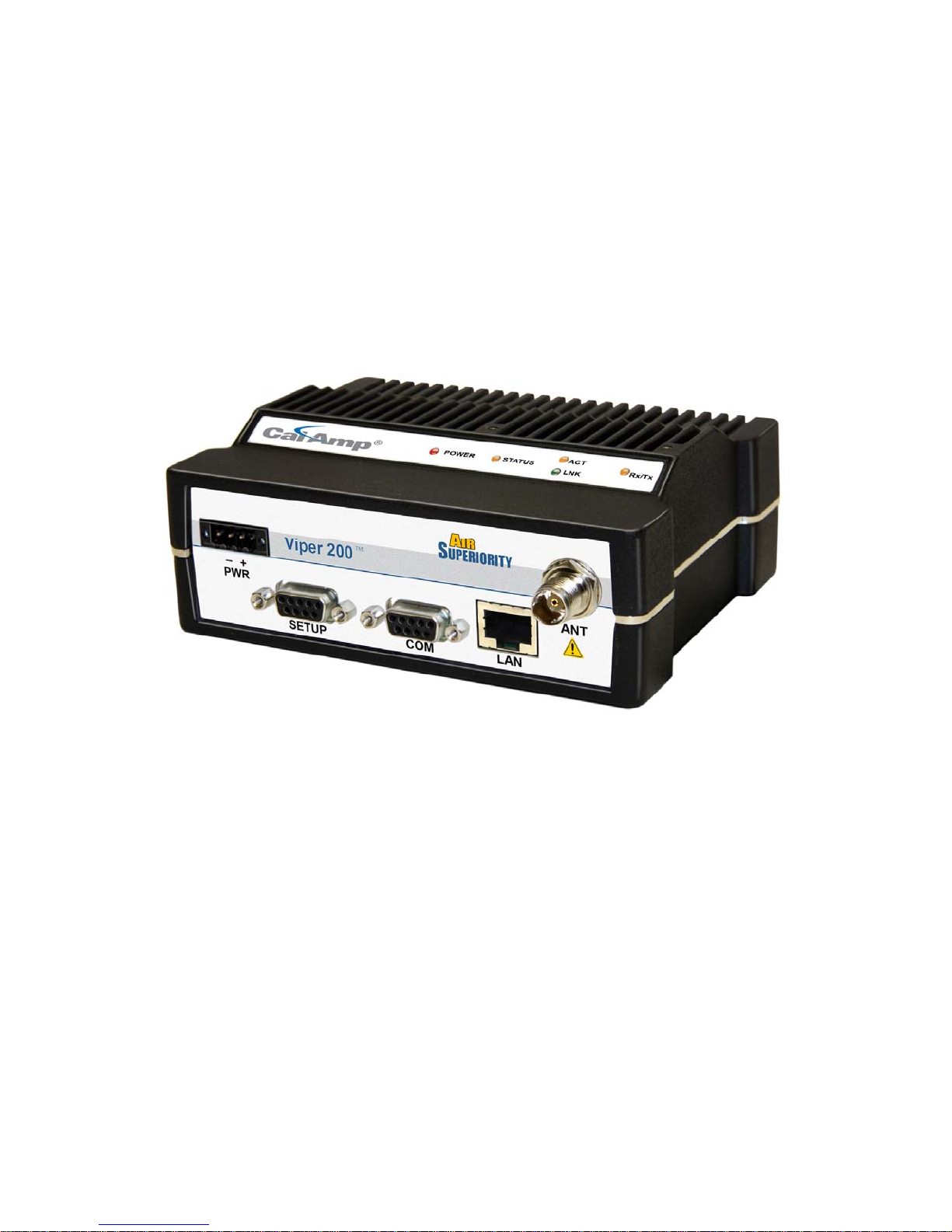
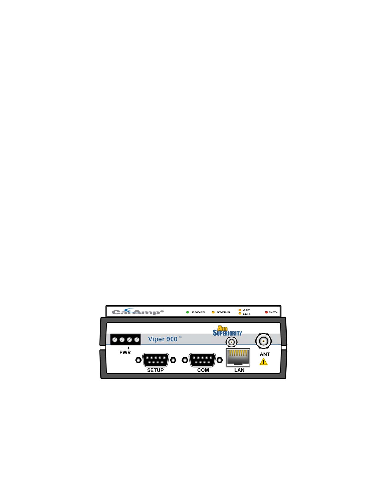
1.3.1 Front Panel
Figure 1.1- Viper Front Panel (Dual-port model shown)
001-5008-000(Rev8) Page 11
Page 12

As shown in Figure 1.1, the front panel has the following connections:
(1) RJ-45 LAN 10 BaseT Ethernet connection with Auto-MDIX
(1) 50-ohm TNC female Antenna connector
(1) 50-ohm SMA female receive antenna connector (Dual-Port models only)
(1) Right-angle power connector (10-30 VDC)
(2) DE-9F RS-232 ports
For Dual-port Viper connections, see Section 1.3.6.
1.3.2 LED Panel
The LED panel has five Tri-Color LEDs. The functionality of each LED is shown in Table 1-1.
Table 1-1- Viper LED Functionality
LED Color Definition
Power Green
Red
Status Green
Blinking Green
Red
Amber (Solid or Blinking)
ACT Blinking Green
Off
Lnk Green
Off
Rx/Tx Green
Red
Viper ready, normal operations
Viper hardware fault
Viper no faults, normal operations
Viper scanning for neighbors
Viper has a fault condition, check unit status
Viper detects high background noise
Ethernet activity detected on PHY link (RJ45)
No Ethernet activity on PHY link (RJ45)
Ethernet connection established (RJ45)
No Ethernet connection (RJ45)
Receiving data
Transmitting data
1.3.3 Ethernet LAN Port
The Ethernet LAN port is an RJ-45 receptacle with a 10 BaseT Ethernet connection and
Auto-MDIX feature. Table 1-2 shows pin-out descriptions for the RJ-45 port.
Table 1-2 - Pin-out for IEEE-802.3 RJ-45 Receptacle Contacts
Contact 10 Base-T Signal
1 TXP
2 TXN
3 RXP
(1)
(1)
(1)
4 SPARE
5 SPARE
6 RXN
(1)
7 SPARE
8 SPARE
SHELL Shield
(1) The name shows the default function. Given the Auto-MDIX capability of
the Ethernet transceiver, TX and RX function could be swapped.
001-5008-000(Rev8) Page 12
Page 13

1.3.4 SETUP and COM Ports
The SETUP and COM serial connections are DE-9F RS-232 ports.
Serial port considerations:
• Viper radio modem SETUP and COM ports are Data Communication Equipment (DCE)
devices
• In general, equipment connected to the Viper’s SETUP / COM serial port is Data
Terminal Equipment (DTE) and a straight-through cable is recommended.
Note: If a DCE device is connected to the Viper SETUP / COM port, a null modem
cable/adapter is required.
The pin-out for the SETUP and COM ports are shown in Table 1-3
Table 1-3- Pin-out for DCE SETUP and COM port, 9 Contact DE-9 Connector
Contact EIA-232F Function Signal Direction
1 DCD
(1)
2 RXD
3 TXD
4 DTR
DTE ← DCE
DTE ← DCE
DTE → DCE
DTE → DCE
5 GND DTE --- DCE
6 DSR
7 RTS
8 CTS
9 RING
(1) Programmable. (2) Always asserted. (3) For future use.
(2)
(1)
(1)
(3)
DTE ← DCE
DTE → DCE
DTE ← DCE
DTE --- DCE
The DCD, DTR, RTS and CTS control lines are programmable. Refer to section 6.4 for serial
port control line configurations.
1.3.5 Power Connector
The Viper is supplied with a right-angle power connector (10-30 VDC). Table 1-4 shows the
pin-out of the power connector.
Table 1-4 - Pin-out of the power connector
Contact #
Color Description
(Left to Right)
4 Fan Power Output (5V)
3 Black Ground
2 Red Positive (10-30) VDC
1 White Enable
Note: The White Enable line must be tied to the red positive lead of the connector for the
Viper to function.
WARNING – EXPLOSION HAZARD- Do not disconnect unless power has been removed
or the area is known to be non-hazardous
WARNING -EXPLOSION HAZARD-Substitution of components may impair suitability for
Class I, Division 2.
The unit is to be powered with a Listed Class 2 or LPS power supply or equivalent.
001-5008-000(Rev8) Page 13
Page 14
1.3.6 Antenna Connector
The standard Viper has a 50-ohm TNC female antenna connector. This connection functions
for both transmit and receive.
The Dual-Port Viper has a 50-ohm TNC female antenna connector functioning for transmit
(only) and a 50-ohm SMA female antenna connector functioning for receive (only). The
separate receive antenna connector allows for unique customer applications that require
additional receive filtering, external PA(s) and other options.
Warning: The transmit antenna port must not be connected directly to the receive
antenna port of the Dual-Port Viper. Excessive power into the receive antenna port
will damage the radio. Input power to the receiver should not exceed 17 dBm
(50mW).
To reduce potential interference, the antenna type and its gain should be chosen to ensure
the effective isotropic radiated power (EIRP) is not more than required for successful
communication.
WARNING – EXPLOSION HAZARD – Do not disconnect equipment unless power has
been removed or the area is known to be non-hazardous.
WARNING -EXPLOSION HAZARD-Substitution of components may impair suitability for
Class I, Division 2.
The antenna connector is for connection to antennas housed inside of a suitable enclosure.
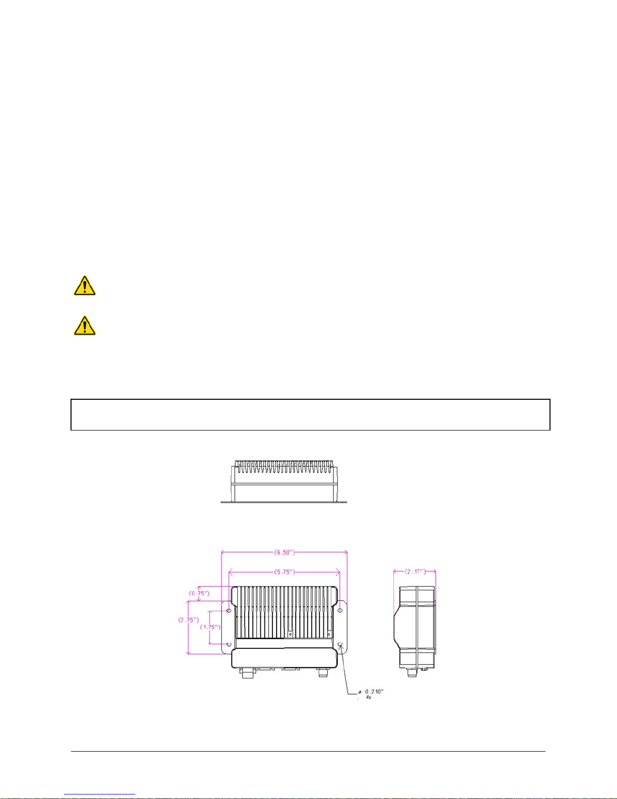
1.3.7 Chassis Dimensions
The equipment is intended for installation only in a RESTRICTED ACCESS LOCATION per
EN60950-1:2006
Figure 1.2 shows the dimensions of the Viper Chassis and mounting plate.
Figure 1.2- Viper Chassis Dimensions (units are in inches)
001-5008-000(Rev8) Page 14
Page 15

1.4 PART NUMBERS AND AVAILABILITY
1.4.1 Viper Radio
Table 1-5 provides a breakdown of the Viper part number
Table 1-5 - Part Number Breakdown
Model Number Description
140-5018-500 Standard VHF Viper
Frequency Range
136 - 174 MHz
140-5028-502 Standard VHF Viper-200 215 - 240 MHz
140-5048-300 Standard UHF Viper Range 3
Standard UHF Viper Range 3
140-5048-400
(EN 300 113 Compliant,
406.1 - 470 MHz
406.1 - 470 MHz
AS/NZ Compliant)
140-5048-500 Standard UHF Viper Range 5
140-5048-600
Standard UHF Viper Range 5
(AS/NZ Compliant)
140-5098-500 Standard 900MHz Viper
450 - 512 MHz
450 - 512 MHz
928 - 960 MHz
140-5018-501 Dual Port VHF Viper 136 - 174 MHz
140-5028-503 Dual Port VHF Viper-200 215 - 240 MHz
140-5048-301 Dual Port UHF Viper Range 3
140-5048-501 Dual Port UHF Viper Range 5
140-5098-501 Dual Port 900MHz Viper
406.1 - 470 MHz
450 - 512 MHz
928 - 960 MHz
1.4.2 Accessories and Options
Table 1-6 - Table 1-8 list standard accessories (including antenna, feedline, and connectors)
tested and approved for use with the Viper.
Table 1-6 - Accessories
ITEM PART NUMBER
Viper Power Cable 897-5008-010
Viper Demo Kit* – VHF - 136-174 MHz 250-5018-500
Viper Demo Kit* – VHF 200 - 215-240 MHz 250-5028-502
Viper Demo Kit* – UHF - 406-470 MHz 250-5048-300
Viper Demo Kit* – UHF - 450-512 MHz 250-5048-500
Viper Demo Kit* – 900 - 928-960 MHz 250-5098-500
Factory Installed Viper Fan Kit 150-5008-001
Field Installed Viper Fan Kit** 150-5008-002
TNC-Male to N-Male 18” 250-0697-103
TNC-Male to N-Male 48” 250-0697-104
TNC-Male to N-Male 72” 250-0697-105
TNC-Male to N-Female 18” 250-0697-106
* The Viper Demo Kit includes two of each of the following: Viper, rubber duck antennas, adapters, attenuators,
power cables, and power supplies.
** The field install Fan Kit is available for all VHF 200/UHF/900 Vipers (140-5028-XXX/140-5048-xxx/140-5098xxx) but is only available for VHF models-(140-5018-xxx) with RF revision 0.3 or greater (shipping Fall 2008).
Contact CalAmp Technical Support for more information.
001-5008-000(Rev8) Page 15
Page 16

Table 1-7 - Antenna Kits
ITEM PART NUMBER
Antenna Kit*: 138-143 MHz 6.5 dBd 250-0211-007
Antenna Kit*: 138-143 MHz 9.5 dBd 250-0211-010
Antenna Kit*: 143-148 MHz 6.5 dBd 250-0211-107
Antenna Kit*: 143-138 MHz 9.5 dBd 250-0211-110
Antenna Kit*: 148-152 MHz 6.5 dBd 250-0211-207
Antenna Kit*: 148-152 MHz 9.5 dBd 250-0211-210
Antenna Kit*: 152-157 MHz 6.5 dBd 250-0211-307
Antenna Kit*: 152-157 MHz 9.5 dBd 250-0211-310
Antenna Kit*: 157-163 MHz 6.5 dBd 250-0211-407
Antenna Kit*: 157-163 MHz 9.5 dBd 250-0211-410
Antenna Kit*: 163-169 MHz 6.5 dBd 250-0211-507
Antenna Kit*: 163-169 MHz 9.5 dBd 250-0211-510
Antenna Kit*: 169-174 MHz 6.5 dBd 250-0211-607
Antenna Kit*: 169-174 MHz 9.5 dBd 250-0211-610
Antenna Kit*: 216-222 MHz 6.5 dBd 250-0221-007
Antenna Kit*: 216-222 MHz 9.5 dBd 250-0221-010
Antenna Kit*: 450-470 MHz, 7 dBd 250-0241-507
Antenna Kit*: 450-470 MHz, 10 dBd 250-0241-510
Antenna Kit*: 890-960 MHz, 6.4 dBd 250-5099-011
Antenna Kit*: 890-960 MHz, 10 dBd 250-5099-021
*Kits include premium antenna, moun ting bracket, surge protector, grounding kit, cable ties, 18” TNC male to N-
male jumper cable and weather kit. UHF/900 kits include 25 feet of LMR400 antenna feedline. Feedline is available
for VHF kits in 25 or 50 feet lengths
.
Table 1-8 - Feedline and Connectors
ITEM PART NUMBER
25 feet antenna feedline (LMR400), N-Male 250-0200-025
50 feet antenna feedline (LMR400), N-Male 250-0200-055
Barrel Connector, RF1 N type, Female 250-0200-100
1.5 PRODUCT WARRANTY
It is our guarantee that every Viper Radio modem will be free from physical defects in
material and workmanship for ONE YEAR from the date of purchase when used within the
limits set forth in Appendix A: Specifications.
The manufacturer's warranty statement is available in Appendix B. If the product proves
defective during the warranty period, contact our Customer Service Department to obtain a
Return Material Authorization (RMA). BE SURE TO HAVE THE EQUIPMENT MODEL, SERIAL
NUMBER, AND BILLING & SHIPPING ADDRESSES AVAILABLE WHEN CALLING. You may also
request an RMA online at www.calamp.com/component/option,com_rma/
FACTORY AND TECHNICAL SUPPORT
M-F 7:30-4:30 CST
CalAmp Wireless Networks Corp
299 Johnson Ave., Ste 110, Waseca, MN 56093
Tel 507.833.8819; Fax 507.833.6758
Email imcsupport@calamp.com
001-5008-000(Rev8) Page 16
Page 17

1.6 RMA REQUEST
When returning a product, mark the RMA clearly on the outside of the package. Include a
complete description of the problem and the name and telephone number of a contact
person. RETURN REQUESTS WILL NOT BE PROCESSED WITHOUT THIS INFORMATION.
Contact Customer Service:
299 Johnson Ave., Ste 110
Waseca, MN 56093
Tel 1.507.833.8819
BE SURE TO HAVE THE EQUIPMENT MODEL AND SERIAL NUMBER, AND BILLING AND
SHIPPING ADDRESSES ON HAND WHEN CALLING.
For units in warranty, customers are responsible for shipping charges to CalAmp Wireless
Networks Corp. For units returned out of warranty, customers are responsible for all
shipping charges. Return shipping instructions are the responsibility of the customer.
1.7 DOCUMENTATION AND DOWNLOADS
CalAmp reserves the right to update its products, software, or documentation without
obligation to notify any individual or entity. Product updates may result in differences
between the information provided in this manual and the product shipped. For access to
the most current product documentation and application notes, visit www.calamp.com/
001-5008-000(Rev8) Page 17
Page 18

22 SSYYSSTTEEMM AARRCCHHIITTEECCTTUURREE AANNDD NNEETTWWOORRKK PPLLAANNNNIINNGG
This section briefly discusses network architecture (including basic network types),
interfacing modems and DTE, data protocols for efficient channel operation, addressing, and
repeaters.
Viper is designed to replace wire lines in SCADA, telemetry and control applications. The
Ethernet and RS-232 serial port allows direct connection to Programmable Logic Controllers
(PLCs) or Remote Terminal Units (RTUs). A SCADA system is defined as one or more
centralized control sites used to monitor and control remote field devices over wide areas.
For example, a regional utility may monitor and control networks over an entire
metropolitan area. Industry sectors with SCADA systems include energy utilities, water and
wastewater utilities, and environmental groups.
The Viper is intended for use in the Industrial Monitoring and SCADA market. The range of
the Viper is dependent on terrain, RF (radio frequency) path obstacles, and antenna system
design. This section provides tips for selecting an appropriate site, choosing an antenna
system, and reducing the chance of harmful interference.
2.1 SINGLE COVERAGE AREA
In a network topology with only a single coverage area (all units can talk to one another
directly), there are several common system configurations.
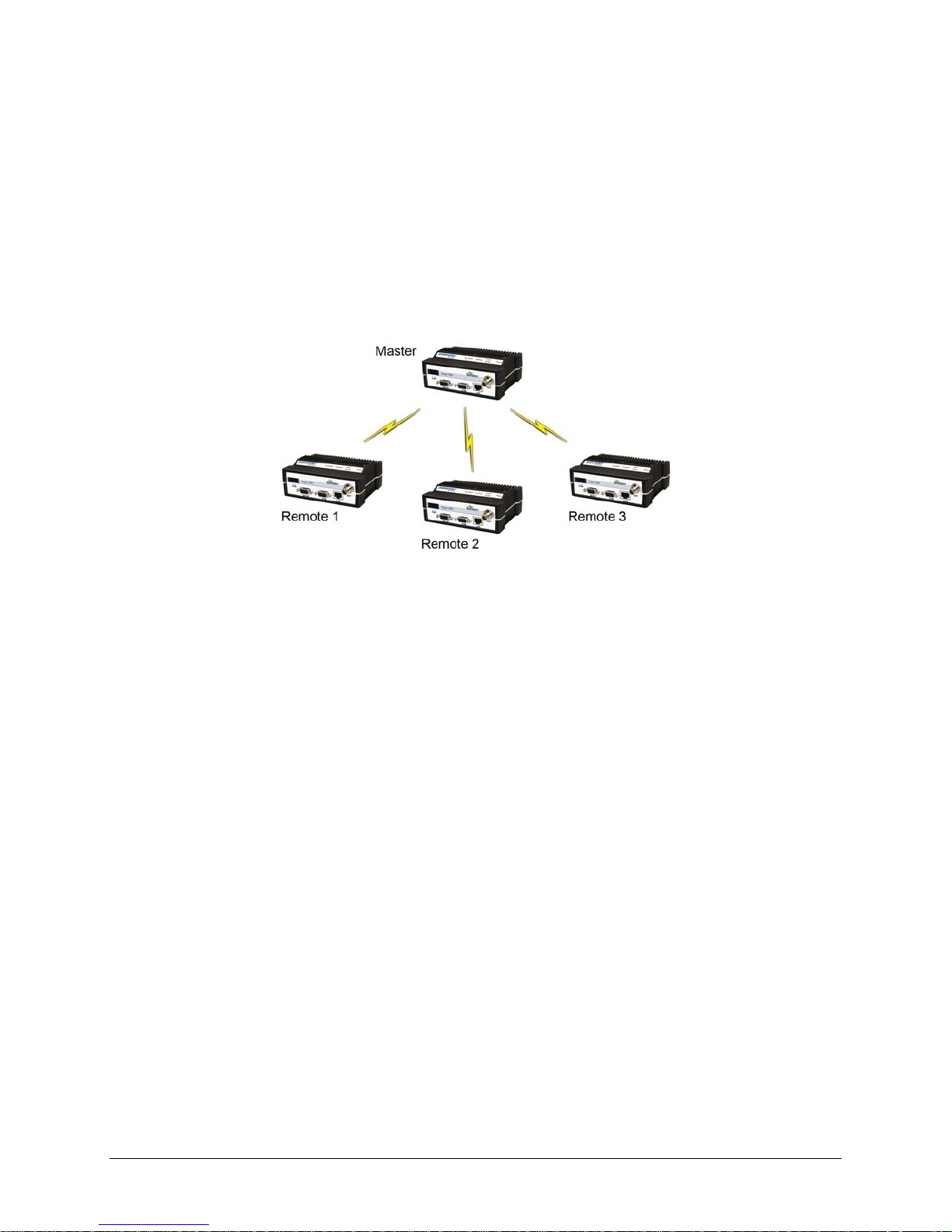
The most common is for one unit to be designated as a master and the rest designated as
remotes. Another system configuration is Report-by-Exception.
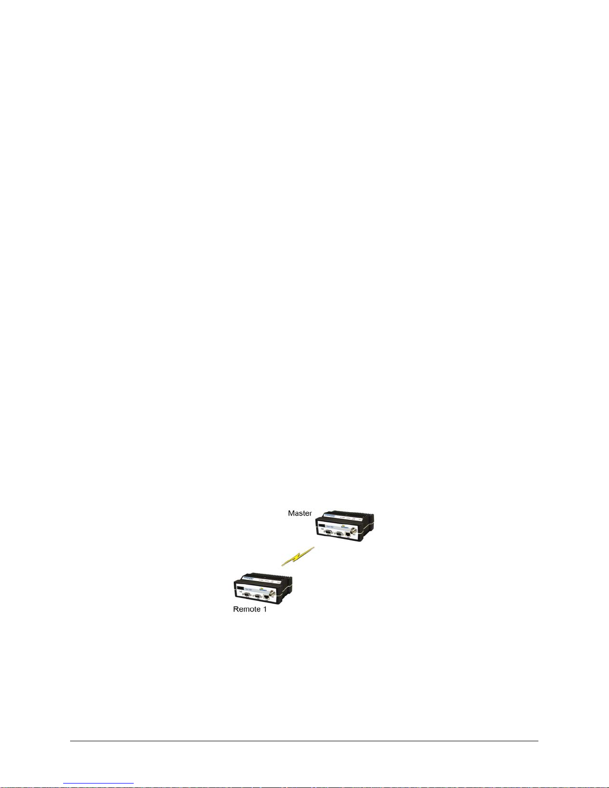
2.2 MASTER/REMOTE
In a Viper network, Vipers are not programmed to be masters or remotes. All Vipers in a
network can be configured the same. However, a unit can be configured as an Access Point.
The unit configured as an Access Point would allow access to the Internet, but an Access
Point is not required in all networks. Most SCADA networks have a “polling master”, but the
polling master is not necessarily configured any different than the remotes. It is the
responsibility of the polling master to control RF traffic so RF collisions do not occur.
Note: In a radio system, only one radio should transmit at a time. If two radios
transmit at the same time to another radio, RF collisions occur. Collisi ons will
slow data traffic and possibly corrupt data.
The Viper has RF collision avoidance technology (checks the air wave for a carrier before
transmitting) and Ethernet CSMA (Carrier Sense Multiple Access). CSMA is an Ethernet
collision avoidance mechanism technology built into to all Ethernet connections. These
technologies still need to be supplemented by the HMI/PLC polling master to optimize RF
data traffic.
Some HMI/PLC Ethernet applications may depend solely on Ethernet CSMA to control the
flow of messages to avoid RF collisions in a Viper network. This may flood the network with
multiple polling messages, making it difficult for the RTUs to acquire the airwave to transmit
their reply messages. This will cause the RTUs to compete for airtime and a dominant RTU
may be created.
While the dominant RTU/radio is transmitting, the other RTUs will send their reply messages
to their connected Viper. Vipers will buffer reply messages because the dominant RTU/radio
is transmitting (carrier is present). A Viper will buffer (while a carrier is present) a reply
message until it can capture the airwave (carrier absent) to transmit. There could be five or
six RTU/radios in a small system (or 10 or 20 in a large system), which could be trying to
001-5008-000(Rev8) Page 18
Page 19
capture the airwaves to transmit. The RTUs will not respond in the order they were polled
but will respond when they are ready and have captured the airwaves. The dominant RTU is
created because it happens to reply at just the right time and be in the right order in the
polling sequence.
A common method for a polling master to manage RF traffic is for the HMI/PLC polling
master to poll one remote at a time. The next polling message is not sent until the current
message has been completed (“Done”) or has timed out. This prevents more than one
outstanding polling message. Ladder logic programs typically refer to these parameters as
the message “Done” and “Error” bits. The “Done” and “Error” bits parameter values can be
adjusted for longer timeout values, if required.
Because the Viper has the ability to use two completely different and separate SCADA
polling protocols, it is important to have interaction between the two protocols. The Viper
can send out an Ethernet TCP/IP polling message and also an RS232 polling message, which
may or may not be generated by the same HMI/PLC. CalAmp recommends the user
program the polling sequence in each protocol with logic that interacts with the other’s
protocol “Done” and “Error” bits. The Ethernet polling protocol would not be allowed to
send a message until the current Ethernet message is either “Done” or “Error” and the
previous RS232 message are either “Done” or “Error” bits are set. The RS232 polling
protocol would also have a similar logic.
POINT-TO-POINT
2.3
A point-to-point network is the most simple of all networks, and may be used for connecting
a pair of PC's, a host computer and a terminal, a SCADA polling master and one remote,
mobile applications (like in-vehicle GPS receivers and base stations) or a wide variety of
other networking applications.
System configurations indicated above allow for either Ethernet or serial interfaces. In
bridge mode, all the network devices are on the same IP subnet. In router mode, the
Ethernet connection on the polling master unit and the remote(s) use different IP subnets.
A hub or switch may be used to allow multiple devices to connect to the Viper radio modem.
Serial connections are transparent pass-through connections, allowing the use of legacy
serial devices in the Viper product environment.
001-5008-000(Rev8) Page 19
Figure 2.1 - Point-to-Point Network
Page 20
2.3.1 Point-to-Multipoint
A Point-to-Multipoint network is a common network type used in SCADA or other polling
systems. The single polling master station communicates with any number of remotes and
controls the network by issuing polls and waiting for remote responses. Individual PLC/RTU
remotes manage addressing and respond when their individual addresses are queried.
PLC/RTU unit addresses are maintained in a scanning list stored in the host program or
master terminal device at the SCADA host site. Communications equipment is transparent
and does not interact with specific remotes; all data is coupled to the host on a single data
line (such a network is commonly used with synchronous radio modems and asynchronous
radio modems).
Figure 2.2 - Point to Multipoint Network
2.3.2 Report by Exception
In a true Report by Exception configuration, the remotes send data to the master only when
an event or exception has occurred in the remote. However, most Report by Exception
systems have a master/remote polling component. The master polls the remotes once every
hour or half-hour to ensure there is still a valid communication path. In a Report by
Exception configuration, there will not be a master controlling RF traffic and RF collisions will
often occur. The Viper has several collision avoidance features to help minimize collisions.
The Viper is a “polite radio”. The Viper will check the RF traffic on the receive channel
before transmitting. If there is no RF traffic present (no carrier present) it will transmit. If
there is RF traffic (carrier present) the Viper will buffer the data. The Viper will transmit the
buffered data when there is no RF traffic present (no carrier present).
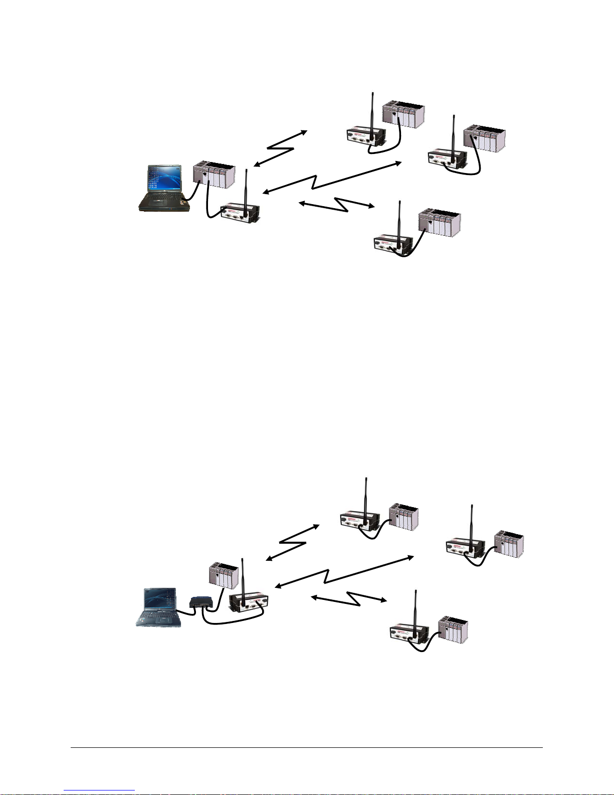
2.4 EXTENDING THE COVERAGE AREA WITH A RELAY POINT
The Viper has a Relay Point feature that allows a unit to relay data from one RF coverage
area to another RF coverage area. When units are spread over two or more coverage areas,
the user must identify the devices forming the backbone between coverage areas so any
unit can talk to any other regardless of their locations. There can be multiple Relay Points
in the system extending the coverage over several hops.
001-5008-000(Rev8) Page 20
Page 21
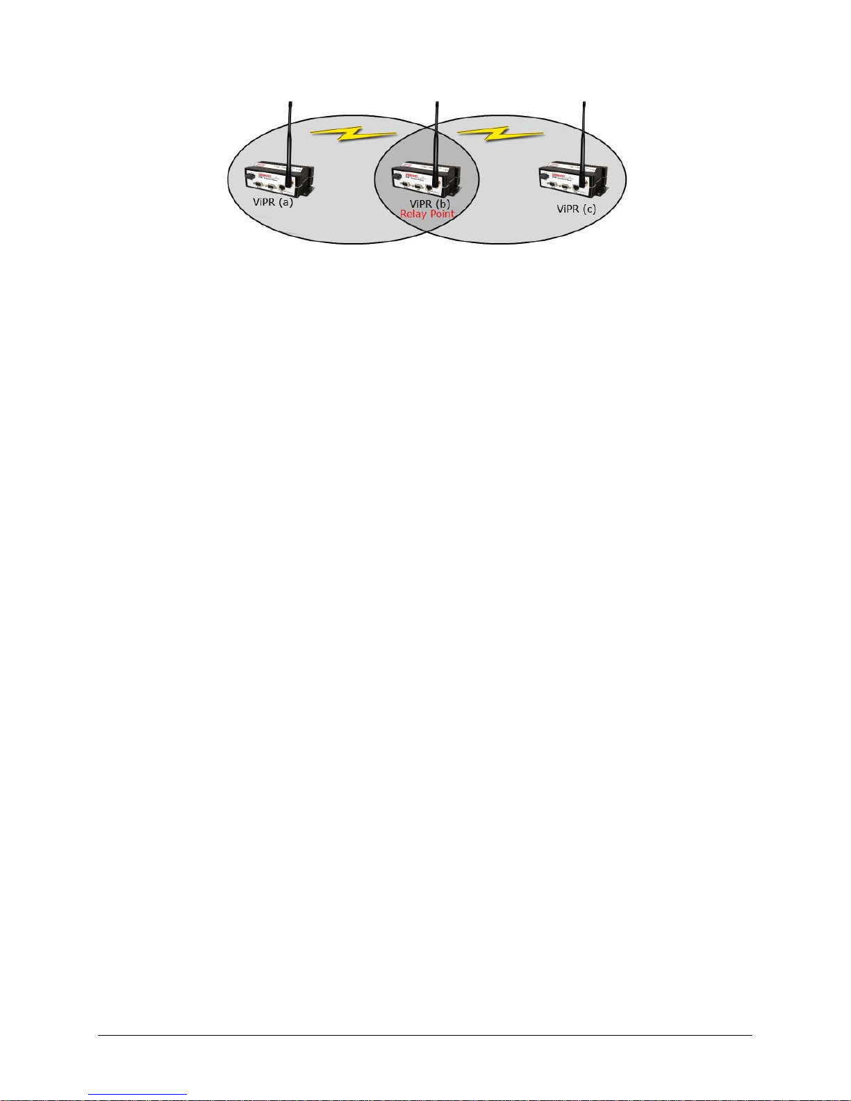
Figure 2.3 - Two Coverage Areas
The unit forming the backbone between the coverage areas must be configured to repeat all
necessary information from one coverage area to the next. This unit must have the Relay
Point parameter enabled (See Section 6.1).
2.4.1 Understanding RF Path Requirements
Radio waves are propagated when electrical energy produced by a radio transmitter is
converted into magnetic energy by an antenna. Magnetic waves travel through space. The
receiving antenna intercepts a very small amount of this magnetic energy and converts it
back into electrical energy that is amplified by the radio receiver. The energy received by
the receiver is called the Received Signal Strength Indication (RSSI) and is measured in
dBm.
A radio modem requires a minimum amount of received RF signal to operate reliably and
provide adequate data throughput. This is the radio’s receiver sensitivity. In most cases,
spectrum regulators will define or limit the amount of signal that can be transmitted and it
will be noted on the FCC license. This is the effective isotropic radiated power (EIRP
).
Transmitted power decays with distance and other factors as it moves away from the
transmitting antenna.
2.5 SITE SELECTION AND SITE SURVEY
2.5.1 Site Selection
For a successful installation, careful thought must be given to selecting the site for each
radio. Suitable sites should provide the following:
Protection from direct weather exposure
A source of adequate and stable primary power
Suitable entrances for antenna, interface, or other cabling
Antenna location with an unobstructed transmission path to all remote radios in the
system
These requirements can be quickly determined in most cases.
001-5008-000(Rev8) Page 21
Page 22

2.5.2 Site Survey
A Site Survey is an RF propagation study of the RF path between two points or between one
point and multiple points. UHF radio signals travel primarily by line of sight and
obstructions between the sending and receiving stations will affect system performance.
Signal propagation is also affected by attenuation from obstructions such as terrain, foliage,
or buildings in the transmission path. A Site Survey is recommended for most projects to
determine the optimal RF paths for each link. This is especially true when more than one RF
coverage area is required. A Site Survey will determine the best unit location for the Relay
Points.
2.6 SELECTING ANTENNA AND FEEDLINE
The Viper can be used with a variety of antenna types. The exact style used depends on the
physical size and layout of a system. The Viper device has been tested and approved with
antennas having a maximum gain of 10 dBi.
2.6.1 Antenna Gain
Antenna gain is usually measured in comparison to a dipole. A dipole acts much like the
filament of a flashlight bulb: it radiates energy in almost all directions. One bulb like this
would provide very dim room lighting. Add a reflector capable of concentrating all the
energy into a narrow angle of radiation and you have a flashlight. Within that bright spot
on the wall, the light might be a thousand times greater than it would be without the
reflector. The resulting bulb-reflector combination has a gain of 1000, or 30 dB, compared
to the bulb alone. Gain can be achieved by concentrating the energy both vertically and
horizontally, as in the case of the flashlight and Yagi antenna. Gain can be also be achieved
by reducing the vertical angle of radiation, leaving the horizontal alone. In this case, the
antenna will radiate equally in all horizontal directions, but will take energy that otherwise
would have gone skywards and use it to increase the horizontal radiation.
The required antenna impedance is 50 ohms. To reduce potential radio interference, the
antenna type and its gain should be chosen to ensure the effective isotropic radiated power
(EIRP) is not more than required for successful communication.
See Table 1-7 for a list of tested antenna recommendations. These antennas are FCC
approved for use with the Viper. Similar antenna types from other manufacturers are
equally acceptable. It is important to follow the manufacturer’s recommended installation
procedures and instructions when mounting any antenna.
2.6.2 Omni Directional Antenna
In general, an omni directional antenna should be used at a master station and Relay
Points. This allows equal coverage to all of the remote locations. Omni directional antennas
are designed to radiate the RF signal in a 360-degree pattern around the antenna. Short
range antennas such as folded dipoles and ground independent whips are used to radiate
the signal in a ball shaped pattern while high gain omni antennas, such as a collinear
antenna, compress the RF radiation sphere into the horizontal plane to provide a relatively
flat disc shaped pattern that travels further because more of the energy is radiated in the
horizontal plane.
001-5008-000(Rev8) Page 22
Page 23
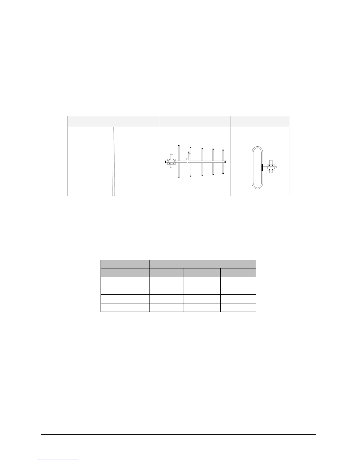
2.6.3 Yagi Antenna
At remote locations (not used as a Relay Point), a directional Yagi is generally
recommended to minimize interference to and from other users.
2.6.4 Vertical Dipoles
Vertical dipoles are very often mounted in pairs, or sometimes groups of 3 or 4, to achieve
even coverage and to increase gain. The vertical collinear antenna usually consists of
several elements stacked one above the other to achieve similar results.
Figure 2.4 - Antenna Types
Omni (Vertical Collinear) Yagi Vertical Dipole
2.6.5 Feedline
The choice of feedline should be carefully considered. Poor quality coaxial cables should be
avoided, as they will degrade system performance for both transmission and reception. The
cable should be kept as short as possible to minimize signal loss. See Table 2-1 for a list of
feedline recommendations.
Table 2-1 - Transmission Loss (per 100 Feet)
Cable Type
LMR-400
1/2” Heliax
7/8” Heliax
1 5/8” Heliax
0.68 dB
0.37 dB
0.22 dB
Frequency Range
VHF
1.5 dB
2.7 dB 3.9 dB
1.51 dB 2.09 dB
0.83 dB 1.18 dB
0.51 dB 0.69 dB
UHF 900 MHz
Outside cable connections should have a weather kit applied to each connection to prevent
moisture. Feedline connections should be routinely inspected to minimize signal loss
through the connection. A 3 dB loss in signal strength due to cable loss and/or bad
connections represents a 50% reduction in signal strength.
2.6.6 RF Exposure Compliance Requirements
The Viper radio is intended for use in the Industrial Monitoring and Control and SCADA
markets. The Viper unit must be professionally installed and must ensure a minimum
separation distance listed in the table below between the radiating structure and any
person. An antenna mounted on a pole or tower is the typical installation and in rare
instances, a 1/2-wave whip antenna is used.
001-5008-000(Rev8) Page 23
Page 24
Table 2-2 – RF Exposure Compliance Minimum Safety Distances
Antenna Gain
5 dBi 10 dBi 15 dBi
Min Safety Distance
(VHF @ max power)
123cm 218.8cm 389cm
Min Safety Distance
(UHF @ max power)
Min Safety Distance
(900 MHz @ max power)
105.7cm 188cm 334.4cm
63.8cm 115 cm 201.7 cm
Note: It is the responsibility of the user to guarantee compliance with the FCC
MPE regulations when operating this device in a way other than described above.
The Viper radio uses a low power radio frequency transmitter. The concentrated energy
from an antenna may pose a health hazard. People should not be in front
of the antenna when the transmitter is operating.
RF Exposure
The installer of this equipment must ensure the antenna is located or pointed such that it
does not emit an RF field in excess of Health Canada limits for the general population.
Recommended safety guidelines for the human exposure to radio frequency electromagnetic
energy are contained in the Canadian Safety Code 6 (available from Health Canada) and the
Federal Communications Commission (FCC) Bulletin 65.
Any changes or modifications not expressly approved by the party responsible for
compliance (in the country where used) could void the user's authority to operate the
equipment.
2.7 TERRAIN AND SIGNAL STRENGTH
A line of sight path between stations is highly desirable and provides the most reliable
communications link in all cases. A line of sight path can often be achieved by mounting
each station antenna on a tower or other elevated structure that raises it high enough to
clear surrounding terrain and other obstructions.
The requirement for a clear transmission path depends on the distance to be covered by the
system. If the system is to cover a limited distance, then some obstructions in the
transmission path may be tolerable. For longer-range systems, any obstruction could
compromise the performance of the system, or block transmission entirely.
The signal strength (RSSI) at the receiver must exceed the receiver sensitivity by an
amount known as the fade margin to provide reliable operation under various conditions.
Fade margin (expressed in dB) is the maximum tolerable reduction in received signal
strength, which still provides an acceptable signal quality. This compensates for reduced
signal strength due to multi-path, slight antenna movement or changing atmospheric
conditions. CalAmp recommends a 20 dB fade margin for most projects.
001-5008-000(Rev8) Page 24
Page 25

2.8 RADIO INTERFERENCE
Interference is possible in any radio system. However, since the Viper is designed for use in
a licensed system, interference is less likely because geographic location and existing
operating frequencies are normally taken into account when allocating frequencies.
The risk of interference can be further reduced through prudent system design and
configuration. Allow adequate separation between frequencies and radio systems. Keep the
following points in mind when setting up your radio system.
a. Systems installed in lightly populated areas are least likely to encounter interference,
while those in urban and suburban areas are more likely to be affected by other
devices.
b. Directional antennas should be used at the remote end of the link. They confine the
transmission and reception pattern to a comparatively narrow beam, which
minimizes interference to and from stations located outside the pattern.
c. If interference is suspected from another system, it may be helpful to use antenna
polarization opposite to the interfering system’s antennas. An additional 20 dB (or
more) of attenuation to interference can be achieved by using opposite antenna
polarization.
d. Check with your CalAmp sales representative or CalAmp Technical Services for
additional options. The Technical Services group has qualified personnel to help
resolve your RF issues.
IP FORWARDING MODES
2.9
2.9.1 Bridge Mode
Bridge mode requires less setup than Router mode. In Bridge mode, the IP Router does not
contain IP/Network properties accessible through the network; they are transparent to the
network. Only the PC Server and the RTU Client’s Network properties need configuration.
The Server’s Gateway will direct the Server to all remote Clients on the network. The PC
Server will broadcast to all the RTU Clients bridged to the PC Server. Bridge mode may be
used when all devices are located on the same Local Area Network (LAN). Figure 2.5 shows
a Viper Bridge Mode configuration.
001-5008-000(Rev8) Page 25
Page 26
192.168.205.100
HMI/PLC
HMI/PLC
Figure 2.5 - Viper Bridge Mode Configuration
Viper
192.168.205.1
Viper
192.168.205.2
Viper
PLC
PLC
Viper
192.168.205.3
PLC
2.9.2
Router mode provides network configuration flexibility and adds RF diagnostics capability for
Viper wireless modems. Router mode also allows greater flexibility in using different
protocols. Diagnostics can be retrieved through the Ethernet port of the Viper. This
configuration is recommended for users who have IT/Network support readily available to
them and the authorization required to make changes in the network. Router mode
requires set up of IP/Ethernet and Serial IP addresses. Figure 2.6 shows a Viper Router
Mode configuration.
Router Mode
HMI/PLC
192.168.205.2
HMI/PLC
192.168.205.10
PLC
192.168.206.2
Viper
192.168.206.1
Viper
192.168.205.1
Figure 2.6- Viper Router Mode Configuration
Viper
192.168.208.1
PLC
192.168.207.2
Viper
192.168.207.1
PLC
192.168.208.2
001-5008-000(Rev8) Page 26
Page 27

2.10 CHOOSING AN IP ADDRESSING SCHEME
All Ethernet capable devices, or hosts, have at least one IP address and subnet mask
assigned to it. The IP address identifies that specific device and the subnet mask tells the
device which other IP addresses it can directly communicate with.
The Viper ships from the factory with a default Ethernet IP address of 192.168.205.1 and a
subnet mask of 255.255.255.0. (This is sometimes written in shorthand notation as:
192.168.205.1/24 since the subnet mask 255.255.255.0 contains 24 ones then 8 zeros
when it is converted to binary.)
The default subnet of the Viper consists of addresses from 192.168.205.0 to
192.168.205.255. The first and last IP address of each subnet is reserved, no matter what
the subnet size is. The first IP address in the subnet is the Network ID. The last IP address
in the subnet is the Broadcast Address. In the Viper’s example, IP addresses 192.168.205.0
and 192.168.205.255 are reserved, and any address(es) from 192.168.205.1 to
192.168.205.254 are valid and may be assigned to a host.
When any host needs to communicate with another device that is not within the same local
area network it will first send the data packet to the gateway or router. The gateway or
router will forward the packet to the desired location. Often times a packet will pass
through several gateways or routers to get to its final destination.
2.10.1
Bridge Mode
In Bridge mode each Viper has only one IP address. Each Viper in the network must be on
the same network and have the same subnet mask. It is recommended that each Viper be
assigned a unique IP address.
Bridge Mode Example 1:
Ethernet Subnet Mask for all units: 255.255.255.0
Network ID: 192.168.205.0
Viper #1: 192.168.205.1 / 24
Viper #2: 192.168.205.2 / 24
Viper #3: 192.168.205.3 / 24
PLC/RTU #1: 192.168.205.4 / 24
PLC/RTU #2: 192.168.205.5 / 24
Computer #1: 192.168.205.6 / 24
…
PLC/RTU #100: 192.168.205.253 / 24
Viper #100: 192.168.205.254 / 24
Broadcast Address: 192.168.205.255
All units are on the 192.168.205.0 network and all units have the same subnet mask.
Because of this, all units can communicate directly with each other. There are 254 valid
IP addresses that may be assigned to hosts on the network.
001-5008-000(Rev8) Page 27
Page 28

Bridge Mode Example 2:
Ethernet Subnet Mask for all units: 255.255.0.0
Network ID: 172.20.0.0
Computer #1: 172.20.0.1 / 16
Viper #1: 172.20.0.2 / 16
Viper #2: 172.20.0.3 / 16
…
Viper #105: 172.20.136.125 / 16
Computer #302: 172.20.138.205 / 16
…
PLC/RTU #500: 172.20.255.253 / 16
Computer #500: 172.20.255.254 / 16
Broadcast Address: 172.20.255.255
This example is similar to Bridge Mode Example #1 except there are 65534 valid IP
addresses that may be assigned to hosts on the network.
2.10.2 Router Mode
In Router mode, each Viper has two IP addresses, an Ethernet IP address and an RF IP
Address. By default each Viper will have the same Ethernet IP Address (192.168.205.1)
and will have a unique RF IP address which is assigned at the factory. The RF IP address
will always have the form 10.x.y.z where x, y, and z is based on the last 6 digits of the
unit’s MAC address.
In Router mode, each Viper must have its Ethernet IP Address on a unique
addition, all Vipers must have their RF IP addresses on the same
network. The default
network. In
network is 10.0.0.0/8. For consistent and reliable communication, the RF network
should not overlap or contain any of the IP Addresses in the Ethernet networks.
Router Mode Example 1:
Ethernet Subnet Mask: May vary from Viper to Viper.
RF Subnet Mask for all units: 255.0.0.0
Viper #1 Eth IP Address: 192.168.205.1 / 24 RF IP Address: 10.11.12.25 / 8
Computer #1: 192.168.205.2 / 24
Viper #2 Eth IP Address: 192.168.206.1 / 24 RF IP Address: 10.9.7.251 / 8
PLC #2: 192.168.206.2 / 24
Computer #2: 192.168.206.3 / 24
Viper #3 Eth IP Address: 192.168.207.1 / 24 RF IP Address: 10.8.0.52 / 8
PLC #3: 192.168.207.2 / 24
Computer #3: 192.168.207.3 / 24
Viper #4 Eth IP Address: 172.21.51.105 / 16 RF IP Address: 10.0.1.11 / 8
PLC #4: 172.21.51.106 / 16
In this example, each Viper has an Ethernet IP address on a unique network. For Vipers
#1, #2, and #3, each network connected to their local Ethernet ports has 254 valid IP
addresses that may be assigned to other hosts. The network connected to Viper #4’s
local Ethernet port has 65534 valid IP addresses.
001-5008-000(Rev8) Page 28
Page 29

Note 1: All the Vipers’ RF IP addresses are on the same network. Because they are
using the 10.0.0.0/8 network, all Vipers may use the default RF IP address programmed
by the factory.
Note 2: All the Viper Ethernet IP addresses are on different networks.
Note 3: Computers, PLCs, RTUs, or other Ethernet capable devices can be connected up
to each Viper’s local Ethernet interface. That device must be set with an IP address on
the same network as the Ethernet interface of the Viper it is connected with.
Router Mode Example 2:
Ethernet Subnet Mask for all units: 255.255.255.240
RF Subnet Mask for all units: 255.255.0.0
Viper #1 Eth IP Address: 10.200.1.1 / 28 RF IP Address: 10.0.0.1 / 16
Viper #2 Eth IP Address: 10.200.1.17 / 28 RF IP Address: 10.0.0.2 / 16
Viper #3 Eth IP Address: 10.200.1.33 / 28 RF IP Address: 10.0.0.3 / 16
Viper #4 Eth IP Address: 10.200.1.49 / 28 RF IP Address: 10.0.0.4 / 16
…
Viper #177 Eth IP Address: 10.200.12.1 / 28 RF IP Address: 10.0.0.177 / 16
Viper #178 Eth IP Address: 10.200.12.17 / 28 RF IP Address: 10.0.0.178 / 16
…
Each Viper has an Ethernet IP address on a unique network.
In this example, each network connected to the Viper’s local Ethernet port has 14 valid
IP addresses that may used for the Viper, PLCs, RTUs, computers, or other Ethernet
equipment that may be connected.
The subnet mask of the RF IP addresses has been changed to ensure that the RF IP
network does not overlap any of the Ethernet networks. In this scenario, the RF IP
addresses must be manually programmed to ensure that every Viper has an RF IP
address in the network and that no RF IP address is used twice.
001-5008-000(Rev8) Page 29
Page 30

33 DDAATTAARRAADDIIOO VVIIPPEERR QQUUIICCKK SSTTAARRTT
3.1 SETUP AND CONFIGURATION
It is easy to set up a Viper network to verify basic unit operation and experiment with
network designs and configurations.
It is important to use a network IP subnet address different from others currently in use in
your test area. This will eliminate unnecessary disruption of traffic on the existing network
while you become familiar with the Viper.
3.2 INSTALL THE ANTENNA
An RX/TX antenna is required for basic operation. For demo units only, connect the antenna
as shown in Figure 3.1 to provide stable radio communications between demo devices.
20 dB, 5 watt max, attenuator
Figure 3.1 - Demo Antenna Assembly
Note:
It is important to use attenuation between all demo units in the test network to reduce the
amount of signal strength in the test environment.
3.3 PC LAN SETUP
On a PC running MS-Windows with an existing LAN connection, connect to the Ethernet
input of the Viper and complete the steps in section 3.3.1
3.3.1 Front Panel Connections
Front panel connections include: (For Dual-port Viper connections see Section 1.3.6.)
(1) RJ-45 10 BaseT Ethernet Connection
(1) 50-ohm TNC female transmit antenna connector
(1) 50-ohm SMA female receive antenna connector (Dual-port models only)
(1) Right-angle power connector (10-30 VDC)
(2) DE-9F RS-232 ports
001-5008-000(Rev8) Page 30
Page 31

Figure 3.2 - Front Panel (Standard model shown)
STEP 1: From the Start menu on your PC, select Settings > Control Panel > Network
Connections
STEP 2: Right-click the Local Area Connection icon to open the Properties box.
Scroll through the list and select Internet Protocol (TCP/IP).
Click Properties to open the TCP/IP Properties box.
STEP 3: Select Use the Following IP Address and enter the following values:
IP Address: 192.168.205.254
Subnet Mask: 255.255.255.0
Default Gateway: (leave empty)
001-5008-000(Rev8) Page 31
Figure 3.3 - PC LAN Setup
Page 32

Figure 3.4 - PC LAN Setup: Step 3
STEP 4: Click OK to apply your changes and complete the connection process. Some
Operating systems may require a reboot to complete the connection process.
3.4 MEASURE AND CONNECT PRIMARY POWER
Primary power for the Viper must be within 10-30 VDC and be capable of providing a
minimum of 10 watt supply for Tx @ 1W, 40 watt supply for Tx @ 5W, or 60 watt supply for
Tx @ 10 W. (In Viper Demo Kits, a power connector with screw-terminals is provided with
each unit.) Observe proper polarity when connecting the cables to the Power Supply. (White
wire must be connected to red wire.)
3.5 CONNECT VIPER TO PROGRAMMING PC
Connect a PC’s Ethernet port to the LAN port using a CAT 5 Ethernet cable. The LINK LED
should turn ON.
Figure 3.5 - Connect Power and Ethernet cable to the Viper.
001-5008-000(Rev8) Page 32
Page 33

On your Internet browser address line, type the factory-default IP address: 192.168.205.1.
Press Enter to open the Network Password screen.
3.5.1 Initial Installation Login
For an initial installation, enter any User Name of 1 to 15 characters and the default
Password ADMINISTRATOR (upper case letters). Click OK. The web interface WELCOME
screen opens. Once setup is completed, change the Viper login password (See Section 8.1).
3.6 CONFIGURE YOUR VIPER USING THE SETUP WIZARD
Viper units are programmed using the web interface. Log into the Viper web interface as
described in Initial Installation Login. Follow the instructions below to configure the Viper
using the setup wizard. All units are factory programmed with an IP address of
192.168.205.1. Repeat these steps to program additional Viper units.
STEP 1: Station Name: Assign a unique Station Name
IP Forwarding Mode: Select Bridge (Mode)
Relay Point: Select No
Access Point: Select No
Multi-Speed Mode: Select Disabled
1
Click “Apply” Click “Next”
Figure 3.6 - Using the Setup Wizard: Step 1
1
This selection will be available for units configured to be rate-followers only. See section 5.1 for more
details on rate-followers and rate-controllers.
001-5008-000(Rev8) Page 33
Page 34

STEP 2: Each Viper is programmed with these defaults:
IP Address: 192.168.205.1
Network Mask: 255.255.255.0
Default Gateway: 0.0.0.0
Figure 3.7 - Using the Setup Wizard: Step 2
To monitor or change configuration remotely, each unit requires a unique IP
Address. When configuring more than one unit, be sure to increment IP addresses.
Click “Apply”. Click “Next”.
001-5008-000(Rev8) Page 34
Page 35

STEP 3: Verify FCC license before completing this step.
Channel ID: Enter 1 for Channel ID
Bandwidth: Enter Bandwidth (in KHz)
Data and Control Packet Bit Rate: Select desired bit rate (in kbps)
RX Frequency: Enter RX Frequency
TX Frequency: Enter TX Frequency
TX Power: Enter 5.0 W
Click “Apply” Click “Next”
Figure 3.8 - Using the Setup Wizard: Step 3
STEP 4: The Viper uses AES-128 bit encryption to protect your data from
intrusion. Use of encryption is optional but we strongly recommend
it for network configuration. The encryption phrase/key must be common
to all units in a network.
Encryption Disabled
Encryption: Click Disabled
Click “Apply”. Click “Next”.
Encryption Enabled
Encryption: Click Enabled
Encryption Pass Phrase: Enter an encryption phrase
Note this phrase for reference later
Click “Apply”. Click “Next”.
001-5008-000(Rev8) Page 35
Page 36

Figure 3.9 - Using the Setup Wizard: Step 4
STEP 5: Click “Done” before completing the remaining steps.
Note: If the “Done” button is not clicked on new units, the units will not
transmit.
To save the network configuration parameters of your Viper, click the
“Save Config” command button. You will see a green success icon on the
bottom left of the page when save is complete.
Figure 3.10 - Using the Setup Wizard: Step 5
If you have changed any parameters marked with a yellow “!” icon, you must cycle power to
the unit using the “Reset Unit” button.
Your unit is now functioning in Bridge Mode.
3.7 CHECK FOR NORMAL OPERATION
To simulate data traffic over the radio network, connect a PC or LAN to the Ethernet port of
the Viper and PING each unit in the network multiple times. Refer to section 10.1 on how to
utilize the Viper PING utility.
001-5008-000(Rev8) Page 36
Page 37

44 VVIIPPEERR WWEEBB MMAANNAAGGEEMMEENNTT
A built-in web server makes configuration and status monitoring possible from any browserequipped computer, either locally or remotely. Status, configuration, and online help are
available without requiring special client software. Setup is password-protected to avoid
tampering or unauthorized changes.
Both the configuration parameters and operating firmware can be updated remotely, even
over the RF network itself, using the standard FTP protocol.
4.1 NAVIGATING THE NETWORK MANAGEMENT SYSTEM
The Web Interface is subdivided in two frames: the left frame allows the user to navigate
the main menu, while the right main frame displays the selected page.
4.2 MAIN MENU
VIPER Main menu grants the user access to Unit Status, Setup Wizard, Basic and Advanced
Setup, Security, Statistics, Maintenance, and Network Management.
4.2.1 Network Management System Commands
The remaining buttons on the Navigator frame are used to save your configurations and
reset the unit.
Apply
This command button writes to RAM. When making an entry into a dialog box, click “Apply”
when you are satisfied with the changes to temporarily apply the value(s) entered to the
001-5008-000(Rev8) Page 37
Figure 4.1 - Viper Welcome Screen
Page 38

relevant parameter(s). Failure to use the “Apply” command button before leaving a
web page will result in the loss of entered selections, addresses, and values.
Cancel
The “Cancel” command only affects the dialog boxes or radio buttons in the opened window.
Save Config
This command button saves the Viper parameters into flash memory. Failure to use this
command button will result in the loss of temporarily entered parameters when the unit is
reset.
Reset Unit
Once satisfied all parameters have been applied and saved, use the “Reset Unit” command
button to make flash changes permanent. When a unit is reset, a 20-second station reset
timer counts down. Status reports Ready when reset is complete.
001-5008-000(Rev8) Page 38
Page 39

5 UN
5 UN
IT STATUS
IT STATUS
The Unit Status windows display device General and Diagnostic information.
5.1 UNIT IDENTIFICATION AND STATUS
Figure 5.1 - Unit Status D General Web Page
Banner
The unit identification and status banner displays Viper software revision information for the
Viper device. Have this information available if contacting CalAmp support.
The banner should read: Dataradio Viper FAMA UHFVHF PROD Vx.y_Rxxx, where:
Product Name Viper
Protocol Name Licensed
Band(s) of Operation VHF 136-174 MHz / 215-240 MHz,
UHF 406.1-512 MHz, 900 928-960 MHz
Production Build Vx.y Rxxx where
Vx.y is Major.minor version number, and
Rxxx is Sequential Package Release Build Number
Station Name
Displays the name of the connected unit. Configured under Setup (Basic) D General D
Station Name.
001-5008-000(Rev8) Page 39
Page 40

Local Time
Displays time zone configuration using UTC time and the configured Time Zone. An SNTP
server can be specified under Setup (Advanced) D Time Source. The time will reset to the
default setting if power is cycled on the Viper unit and no SNTP server is configured.
CWID
Continuous Wave Identification - Default = Disabled
Allows the user to broadcast their FCC call sign.
CWID Call sign is the user's FCC call sign to be broadcast.
CWID Interval is the time interval in minutes that the call sign will be broadcasted.
CWID can be configured under Setup (Basic) D General.
IP Forwarding Mode
Displays IP forwarding mode (Bridge or Router). The IP Forwarding Mode can be configured
under Setup (Basic) D General D IP Forwarding Mode.
Station relay point
Displays if the unit is being used as a relay point (Yes or No). The Station Relay Point can be
configured under Setup (Basic) D General D Station relay point.
Multi-Speed Mode
Displays if a unit is in multi-speed mode (enabled), or not (disabled).
When Multi-Speed mode is disabled (default), the units communicate with each other at a
fixed speed. This data rate is user programmable and must be programmed on each Viper
unit.
Enabling multi-speed mode on a standard Viper will configure the unit to be a rate-follower.
In this mode, the unit will adjust its over-the-air data rate to that of the rate-controller.
The rate-controller feature is not available on the standard Viper unit. It is only available
with the 19’’ rack mount Viper Base Station. With the Viper Base Station, the user can
configure the master Viper(s) to be rate-controllers. The user can then configure the ratecontroller to talk at different over-the-air data rates for each remote Viper. This allows the
user to uniquely control the data rate for each RF link in the system from the Base Station
web pages. The user can program RF links with strong signal strength to communicate at
fast data rates and RF links with low signal strength can be programmed to communicate at
more robust, slower data rates. The data rates chosen must all use the same bandwidth.
In a network operating with Multi-Speed, there will normally be one rate-controller (Viper
Base Station) with all other units configured to operate in rate-follower mode.
ETSI (European Telecommunications Standards Institute)
Displays if the unit is in ETSI Mode (enabled/disabled).
Note: This parameter is not user settable. It is programmed by the factory for European or
Australian/New Zealand approved Viper models.
001-5008-000(Rev8) Page 40
Page 41

On-line diagnostics Interval
Displays the time interval in seconds when the On-line Diagnostics will be transmitted. This
interval can be configured under Setup (Basic) D General D On-line diagnostics interval.
VPN Status
Displays the status of the VPN (virtual private network).
Displays “ OK, ready” when operational.
Displays “Not Ready” and a reason, example” VPN service disabled”, when not operational
Unit Status
Displays the status of the Viper and reports any errors. If you do not receive the OK
indicator (EX. Error: Power On Self Test FAILURE, Warning: Radio TX Synthesizer lock
failure N/A), use the ACKNOWLEGDE UNIT STATUS and REFRESH buttons to reset the
modem. If the problem persists, contact CalAmp Technical Services for additional
information.
Have the displayed Unit Status message available if contacting CalAmp support. This
information is also required if returning a unit for service under RMA.
Refresh
This button will refresh the parameters on the current page.
Acknowledge Unit Status
This button allows the user to acknowledge and clear errors.
Errors remain stored, even after cycling power, to aid in troubleshooting intermittent faults.
Press the "Acknowledge Unit Status" button to return web page displays and Status LED
function to normal operation.
5.2 DIAGNOSTICS
Viper units continually monitor and report on their environmental and operating conditions.
5.2.1 Local Diagnostics
Local Diagnostics can be accessed by loading the Unit Status D Diagnostics web page from
the Viper.
Figure 5.2 - Unit Status
001-5008-000(Rev8) Page 41
D
Diagnostics Web Page
Page 42

Date and time
Displays the time and date. To set the time, an SNTP server must be setup under Setup
(Advanced) D Time Source. The SNTP server must also be accessible via the user’s LAN or
Internet connection.
Time since reset
Displays the amount of time since the unit was last reset. [DD,HH,MM,SS], Days, Hours,
Minutes, Seconds
Modem Firmware Version
Displays the modem firmware version of the unit.
Radio Firmware Version
Displays the radio firmware version of the unit.
RSSI from RF-MAC
Displays the Received Signal Strength Indication (RSSI) from the unit with the MAC address
displayed. The RSSI displayed range is from approximately -50 dBm to
-120 dBm. At signal strengths greater than -50 dBm, the radio will still operate but will not
display an accurate RSSI value.
DC Input Voltage
Displays the DC Input Voltage for the unit.
TX Frequency
Displays the current operating transmit frequency for the active channel. Setup (Basic) D
Channel Table D TX
RX Frequency
Displays the current operating receiver frequency for the active channel. Setup (Basic) D
Channel Table D RX
Transmit Power Level
Displays the programmed power level for the active channel. Setup (Basic) D Channel
Table D PA Power
Transceiver Temperature
Displays the transceiver’s internal temperature in Celsius or Fahrenheit. Setup (Advanced)
D User Settings
PA Forward Power
Displays the actual measured forward power of the transmitter. If the measured forward
power drops 1 dB or more below the user configured power level, this line will report
“(fault)”. When the forward power is within range, this line will report “(normal)”. The
Viper radio can be configured to send an SNMP trap (or alarm) if the Forward Power goes
into a “fault” state.
001-5008-000(Rev8) Page 42
Page 43

PA Reverse Power
Displays the actual measured reverse power of the transmitter. If the measured reverse
power increases to within 3 dB of the user configured power level, this line will report
“(fault)”. When the reverse power is within range, this line will report “(normal)”. The
Viper radio can be configured to send an SNMP trap if the Reverse Power goes into a “fault”
state.
Power state
Indicates if the unit is running at full power or at a reduced power. The TX power will
foldback when the temperature is too hot or the Power Amp (PA) current is too high. In
extreme cases of high temperature or high current, the Viper transmitter will shutdown
completely to protect the radio from permanent damage.
When the Viper is at Full power this line will report “(normal”). If the Viper’s PA goes into
Foldback or Shutdown this line will report “(fault)”. The Viper radio can be configured to
send an SNMP trap if the Power State reports a fault.
Refresh
This button will refresh the current page's parameters.
5.2.2 Online Diagnostics
Transmission of online diagnostics may be enabled or disabled at any station or stations
without affecting their ability to communicate with other stations. Online Diagnostics can be
sent anywhere, including being back-hauled. Back hauling adds to the network traffic flow
and must be taken into account when designing a network. If a return flow is necessary, it
needs to be reduced substantially to have a minimal effect on the network.
Viper can support up to 4 diagnostics socket connections at once. This may be used, for
instance, to carry out monitoring at a main office and at up to three separate field locations.
It is also possible one of the four connections use a serial port instead by enabling it on the
Viper’s web browser interface.
Output Format
The online diagnostic output is man/machine readable, ASCII, comma-delimited format. Any
reader program used (or written) must decode the VERSION FIELD and check for type 1 as
more types may be released in the future.
From a Command Prompt window, type telnet nnn.nnn.nnn.nnn 6272 and the unit’s online
diagnostic output will display on the screen (where nnn.nnn.nnn.nnn is your unit’s IP
address in dot decimal format). Note: no overhead is generated in the Viper unit if no
online diagnostic connection is actually made.
001-5008-000(Rev8) Page 43
Figure 5.3 – Diagnostic output sample
Page 44

Host
Table 5-1– Online Diagnostics Output Sample Definitions
MAC address of the station where diagnostic measurements are being collected.
The host will collect diagnostic message from itself and all remote units with IPSD
enabled. IPSD can be enabled/disabled under Setup (Advanced) D IP Services.
Ver
Version of the online diagnostics. Different versions may have different
parameters. This document describes Version 1.
# Number of items that follow in the online diagnostic message.
Period
PERIOD (Seconds). Specifies the time between the generation of online diagnostic
messages from the source station.
Flags Online Diagnostic Flags. (CalAmp specific)
Source Address. In Bridge mode, this address displays the MAC address of the
Source
source Viper. In Router mode, this address displays the IP Address of the source
Viper. The source is the Viper station generating the diagnostic message. This is
also the source station from the point of view of the RSSI measurements
Destination Address. In Bridge Mode, this address displays the MAC address of the
Destination
destination Viper. In Router Mode, this address displays the IP Address of the
destination Viper. This is the destination station from the point of view of RSSI
measurements.
A
Temperature of the source Viper in Celsius or Fahrenheit. Temperature units can
be configured on the source Viper under Setup (Advanced) User D Settings.
Source supply voltage in excess of 8 volts, shown in 10ths of volts.
B
C
D
E
F
G
Supply voltage = (ODM_reading / 10) + 8
A reading of 35 shall be interpreted as 11.5V.
RSSI measured at the source Viper for the last message received from the
destination Viper. This is also referred to as the Local RSSI. The value displayed
shall be interpreted as shown in Table 5.2.
RSSI measured at the destination Viper for the last message received from the
source Viper. This is also referred to as the Remote RSSI. The value displayed
shall be interpreted as shown in Table 5.2.
Radio/antenna forward power measured in 10ths of watts at the source Viper. A
value of 51 shall be interpreted as 5.1W.
Radio/antenna reverse power measured in 10ths of watts at the source Viper. A
value of 2 shall be interpreted as 0.2W.
PER measured at the source. This is calculated as the percentage of packets
rejected due to an invalid header/checksum over the total number of packets
received. To fit a small unsigned integer, this value is multiplied by 1000 and its
max value limited at 255. A reading of 2 means 0.002% of packets were rejected.
Table 5-2 – Online Diagnostics RSSI Display
001-5008-000(Rev8) Page 44
Page 45

VALUE RSSI NOTES
0 NA The RSSI Value is not Available
1 > -60.25 dBm The RSSI Value is greater than –60.25 dBm
20 -65.00 dBm
255 < -123.75 dBm RSSI is less than –123.75 dBm
X RSSI = -60 – (X * 0.25), for X not equal to 0
001-5008-000(Rev8) Page 45
Page 46

6 SETUP (BASIC)
6.1 GENERAL SETUP
Station Name
Station name identifier – Enter a string up to forty characters in length.
IP Forwarding Mode
Bridge / Router, Default = Bridge mode
Bridge Mode: Bridge mode is the simplest configuration for the Viper radio and should only
be used for small networks. In Bridge mode, all the Vipers and all the Hosts/PCs connected
to the Vipers must be on the same IP subnet. Figure 6.2 illustrates Viper bridge mode
configuration. Ethernet messages are sent over the air as broadcast messages. All the
other Vipers in the network will receive the message and relay it to their local area network.
If the Com Ports are configured for Serial/RF Bridge mode on all the Vipers in the network,
then each message that is transmitted into one Viper’s Com Port will be received by all the
other Vipers in the network and transmitted out their Com Ports.
001-5008-000(Rev8) Page 46
Figure 6.1 - Setup (Basic)
Page 47

Note: This configuration can be substituted for a traditional serial RS232 radio system
configuration. The Viper in bridge mode is a drop in replacement for a serial radio.
Bridge Mode
Subnet 192.168.205.0
PLC
192.168.205.20
PLC
192.168.205.30
HMI/PLC
192.168.205.10
Viper
192.168.205.2
Viper
192.168.205.3
HMI/PLC
192.168.205.1
Viper
192.168.205.1
Viper
PLC
192.168.205.
192.168.205.4
Figure 6.2 - Viper Bridge Mode Configuration.
Router Mode: Router mode offers several advantages over Bridge mode and can be used
for simple or complex networks. In Router mode, each Viper must be configured for a
unique IP subnet. Figure 6.3 represents a Viper router mode configuration. Ethernet
messages will be routed to the intended recipient Viper and will be discarded by other
Vipers that overhear the message that was not intended for them. The user can specify the
route a multiple hop message will travel and thus can channel the traffic throughout the
Viper network to give a more reliable connection or perhaps relieve traffic congestion on a
large network. In Router mode, the user has access to the RSSI for each Viper that is one
hop away. In Router mode, several retry mechanisms can be enabled which often yields a
more stable and reliable link. (See section 12, Network Optimization, for more details.)
Also, the user will have access to more advanced IP configuration settings such as Network
Address Translation (NAT).
Router Mode, Different Subnets
192.168.205.0, 192.168.206.0,
192.168.207.0, 192.168.208.0
PLC
192.168.206.2
PLC
192.168.207.2
HMI/PLC
192.168.205.2
Viper
192.168.206.1
Viper
192.168.207.1
HMI/PLC
192.168.205.100
Viper
192.168.205.1
Figure 6.3 - Viper Router Mode Configuration
001-5008-000(Rev8) Page 47
PLC
192.168.208.2
Viper
192.168.208.1
Page 48

Bridge Forwarding
Everything / IP and ARP types only
By default, the Viper only forwards IP and ARP packets (Ethernet II types: 0x0800,
0x0806). By selecting the "Everything" setting, the Viper will forward all 802.3 Ethernet II
packet types. Use this setting to transport protocols such as IPX, 802.1Q, etc. Note that
this option is not available in Router mode because the Viper will automatically forward all
packets per its routing table.
Relay Point
Yes/No (default)
For units that are spread over multiple RF coverage areas, the user needs to identify the
ones that will form the backbone between the coverage areas so that any unit can talk to
any other unit in the network regardless of their locations. These units are called Relay
Point units. A Relay Point provides store and forward repeating for all traffic in Bridge mode
and for broadcast packets in Router mode. Selecting this parameter will force the unit to
repeat all necessary information from one coverage area to the next. Multiple Relay Points
can be configured in parallel to provide redundancy in the network; however, having
redundant relay points may slow the flow of traffic.
Access Point
Yes/No (default)
This is the default gateway (WAN access) of a Viper network. One, and only one, access
point may be defined for each Viper network. All Vipers in the network will set their default
route to point towards the Access Point. (An Access Point can only be configured in Router
mode.)
Multi-Speed Mode
Enabled/Disabled (default) –rate-follower only
See section 5.1 for more information about rate-follower and rate-controller.
When Multi-Speed mode is disabled, the units communicate with each other at a fixed
speed.
A remote Viper unit which has been factory configured to be a rate-follower, can be set to
operate in Multi-Speed mode. In this mode, the remote unit will adjust its speed to that of
the rate-controller that it is talking to. When a remote Viper is not in Multi-Speed mode, it
will use its default configuration speed.
CWID
Enabled/Disabled (default).
Enabling CWID allows the unit to broadcast the FCC Call Sign in Morse code at a certain
interval.
CWID Call sign is the FCC Call sign to be broadcast.
CWID Interval is the time interval after which the call sign will be broadcast.
001-5008-000(Rev8) Page 48
Page 49

On-line diagnostics Interval
The on-line diagnostic interval is the time interval in which the unit will broadcast the
diagnostic string. Please refer to section 5.2.2 for detailed information about the format of
the diagnostic string.
Unit Automatic Reset
Enabling this option will make the radio completely shut down and restart after a set period
of time. The time between resets (in minutes) can be specified in the Unit Reset Interval
field.
6.2 IP SETTINGS
Figure 6.4 - Setup (Basic)
6.2.1 Ethernet Interface
DHCP Client
DHCP Client: Static (default) or Dynamic. When the unit is in Router mode, Static mode
allows the user to set the IP address of the unit. Dynamic mode will set the unit to be a
DHCP client, which will allow the unit to accept an IP address from an external DHCP server.
When the unit is configured for Bridge mode, the Dynamic option is disabled and the user
must enter in a specific IP Address.
NOTE: Activating this option will reset the IP address of the unit. If your network supports
the DHCP Server capability, make sure the IP address assigned by the DHCP server will be
001-5008-000(Rev8) Page 49
D
IP Settings Web Page
Page 50

accessible to you. If your network does not support DHCP server capability, the unit will be
reset to the default (192.168.205.1) IP address within the first 2 minutes.
To activate, select the "DHCP Client” radio button, click on the "Apply" button, click on the
"Save Config" button, and reboot the Viper.
IP Address
Set to a valid unique IP address for each individual unit (default: 192.168.205.1). In Bridge
mode, all the Vipers must be configured for the same IP subnet. In Router mode, each
Viper must be configured for a unique subnet.
Netmask
Set to a valid IP Netmask for each individual unit (depends on customer's IP network
topology, default: 255.255.255.0).
DHCP Server
DHCP Server Disabled, Enabled (Default). The Dynamic Host Configuration Protocol provides
a framework for passing configuration information.
E.g.: Assigns IP address to Hosts (i.e. PC/RTU) on a TCP/IP network.
Start Address
Pool of addresses allocated for DHCP purpose. If a unit is configured as a DHCP Server, this
field represents the start IP address pool managed by the DHCP Server. Normally, Viper
automatically calculates the Lease Start Address (equal to Ethernet IP Address plus one).
Number of Leases
Maximum number of DHCP client(s) a unit can serve.
Lease Duration
The period over which the IP Address allocated to a DHCP client is referred to as a "lease".
Lease Duration is the amount entered in minutes. If 0 (zero) is entered, the lease will not
expire.
Gateway
The Gateway text box displays the IP address of the gateway assigned by the DHCP server.
In Router mode, the default (preset) gateway is the IP address of the unit itself. In Bridge
mode, the default (preset) gateway is 0.0.0.0. To override the default setting, enter a valid
IP address in the text field.
MTU
Maximum Transfer Unit - Default = 1500 bytes. The MTU is the maximum number of bytes
the unit will send in a packet. The input range is from 576 to 1500.
MAC Address
The Ethernet MAC address (media access control) is the unique address that a manufacturer
assigns to each networking device. AA:BB:CC:DD:EE:FF The user can not change the
Ethernet MAC address.
001-5008-000(Rev8) Page 50
Page 51

6.2.2 RF Interface
IP Address
The RF IP address (default: assigned by factory based on the unit's MAC address) is the RF
IP address that is used when sending data and control packets in a Viper network.
Netmask
The Netmask (default: 255.0.0.0) is set to a valid common RF IP Netmask for all units in a
Viper network.
MTU
Maximum Transfer Unit - Default = 1500 bytes. The Maximum transfer unit is the
maximum number of bytes the unit will send in a packet. The input range is from 576 to
1500.
MAC
The RF MAC is a shortened version of the Ethernet MAC address which is used to identify
the radio to other Vipers on the network. The default RF MAC address is assigned by the
factory and is equal to the last six digits of the Ethernet MAC address (DD:EE:FF). The user
can override the default RF MAC address by entering the new RF MAC address in the MAC
address field under the RF Interface section.
When the network is configured for router mode, this feature is useful when replacing a
Viper in the field with a new one. The new Viper can be programmed to have the same RF
MAC, Ethernet IP Address, and RF IP Address as the Viper that is being replaced. When the
new Viper is installed, neighboring Vipers in the network will not know the original Viper was
replaced. Neighboring Vipers will not need to have their neighbor tables updated.
The RF MAC address must be unique for each Viper in the network. This applies to both
Bridge and Router mode configurations.
6.2.3 Default Gateway
The Default Gateway (default: 0.0.0.0) allows the user to enter in the IP address of the
access point to be used as the gateway to the management network. If there is one Viper
configured as an Access Point in the network, all the other Vipers will set their Default
Gateway equal to the RF IP address of the Access Point.
6.3 CHANNEL TABLE
The Channel Table will display the Transmit Frequency, Receive Frequency, Transmit Power,
Bandwidth, and Data Rate for each channel in the unit. Remember to click “Apply” at the
bottom of this page after making any changes.
001-5008-000(Rev8) Page 51
Page 52

Figure 6.5 - Setup (Basic) D Channel Table Web Page
001-5008-000(Rev8) Page 52
Page 53

Radio Capabilities
Tx & Rx Frequency Range and Output Power Range is factory set.
140-5018-500/501: VHF, 136.000-174.000 MHz, 1-10W
140-5028-502/503: VHF, 215.000-240.000 MHz, 1-10W
140-5048-300/301: UHF Range 3, 406.125-470.000 MHz, 1-10W
140-5048-500/501: UHF Range 5, 450.000-511.975 MHz, 1-10W
140-5098-500/501: 900, 928.000-960.000 MHz, 1-8W
Current Radio Settings
Displays the current Rx & Tx Frequencies, Output Power, and Channel Type programmed
into the radio.
Channels
Transmitter Disabled radio button is set at the factory to disable the radio until a valid
frequency has been entered. The radio will not transmit until a valid frequency has been
entered and the transmitter has been enabled.
There are 32 channels available in the Viper. The radio button beside each channel will
select that channel as the active channel. Each channel can operate in simplex (one
frequency) or half duplex (pair of frequencies) mode. The transmit power output level can
be set for each channel. The channel type can be selected for each channel. All Vipers in a
network must be set to the same bandwidth.
Available data rates and bandwidth vary by model. Please refer to Modem/Logic section of
Appendix A for available bandwidths and data rates.
Note: It is the installer’s responsibility to check the FCC license to determine the correct
parameters and settings for channel frequencies, power level, and channel type.
6.4 SERIAL PORTS SETUP
The Viper has two serial ports. Either port can be configured to send data over the air,
connect to the CLI (command line interface), report online diagnostics, or be custom
configured to send/receive data on a specific port to/from a specific IP address.
By default the Setup port is configured to connect to the CLI at 19200 baud. The Com port
is configured to send data in DOX mode at 9600 baud. By default the Com port will send
data as a UDP multicast message to all the other Vipers on the network (10.255.255.255)
on port 6278. When DOX mode is selected on the Setup port, the Setup port will send data
as a UDP multicast message to all the other Vipers on the network on port 6277. If other
configurations are needed, the Viper allows for custom configuration of the transport
protocol, IP Addresses, and ports the Setup port and Com port will connect with.
The serial custom configuration will allow the user to program the serial port as a terminal
server. A terminal server will translate the serial protocol to an Internet Protocol (IP). A
terminal server will wrap serial data presented at the serial port in an IP package (IP header
and associated checksums). When an IP message is sent to the terminal server’s
corresponding IP address, the IP package is stripped off.
001-5008-000(Rev8) Page 53
Page 54

A terminal server will not translate HMI/PLC polling message protocols that are not designed
to be wrapped in an IP package. Most SCADA protocols are not designed to be used with a
terminal server. As an example, the Modbus RTU message is a serial protocol. The Modbus
TCP/IP protocol is an Ethernet IP protocol. The Modbus RTU message cannot be wrapped in
an IP package to form a Modbus TCP/IP polling message. A protocol translation must take
place. A device can be purchased that will perform the translation. Please contact your local
SCADA dealer or CalAmp Tech Support to determine if your SCADA protocol can be used
with a terminal server.
After any settings on this page are updated, press the "Apply" button. Wait for the page to
reload then press the "Save Config" button then the "Reset Unit" button to update the
changed serial port settings.
Figure 6.6 - Setup (Basic) D Serial Ports Web Page
001-5008-000(Rev8) Page 54
Page 55

6.4.1 Basic Settings
Enabled Checkbox
There are independent check boxes to activate SETUP PORT and/or COM PORT.
Speed
The Setup port can be configured for 300, 1200, 2400, 4800, 9600, or 19200 Baud Rate.
The Com port can be configured for 300, 1200, 2400, 4800, 9600, 19200, 38400, 57600, or
115200 Baud Rate.
The default is 19200 for the SETUP port and 9600 for the COM port. The Baud Rate should
be configured to match the settings of the connected device.
Data bits
Number of bits making up the data word. The default is 8. This should be configured to
match the settings of the connected device.
Stop bits
Marks the end of the serial port data byte. The default is 1. This should be configured to
match the settings of the connected device.
Parity
Added to identify the sum of bits as odd or even. The default is none. This should be
configured to match the settings of the connected device.
DCD Control
The DCD (Data Carrier Detect) line can be set for one of the following: Always Asserted,
Never Asserted, or Envelope Mode (the DCD will be asserted only when data is present at
the serial port).
Packet Forwarding Threshold
Mark Character time allows the user to change time based on the character length to
forward the packet.
Flow Control
Allows the user to implement RTS/CTS flow control or no flow control. Note: Request to
Send and Clear to Send flow control will require a 5 wire connection to the Setup Port or
Com Port.
Connection Control
Select "Permanent (3-wire)" when the serial port is always enabled or "Switched (DTR
bringup/teardown)” when DTR is used to enable/disable the serial connection. This should
be configured to match the settings of the connected device.
6.4.2 IP Gateway Service
The serial ports can be configured to provide several different services as listed below.
001-5008-000(Rev8) Page 55
Page 56

CLI Service
Command Line Interface
Access to the Command Line Interface command shell is password protected and is
reserved for authorized Dataradio maintenance personnel.
Serial/RF Bridge - DOX mode
3 wire connection required. Data is sent whenever it is present at the port. Flow control is
not required. The IP Gateway service will use UDP transport protocol to send and receive
messages.
Serial/RF Bridge - RTS/CTS mode
5 wire connection required. Data is sent after the device raises the RTS and the Viper
returns a CTS signal to the device.
Online Diagnostics
TCP/IP based RF diagnostics for the entire Viper network will be collected and sent to the
serial port.
Custom
Choosing Custom enables the user to specify the IP Gateway Transport configuration. The
defaults are CLI Service for SETUP port and Serial/RF Bridge for COM port.
6.4.3 IP Gateway Transport
The Viper allows the user to select between two commonly used protocols for sending data
to/from the serial port. The first method, TCP, provides a reliable method of transmission,
with acknowledgements and retries built into the protocol. The TCP protocol requires
several handshaking messages to open a connection, close a connection, and to
acknowledge that a packet has been received correctly. These handshaking messages will
add some extra traffic to the network.
The second method, UDP, is a simpler method of sending data. Connections do not need to
be opened or closed before sending data, as in TCP. Therefore, no extra handshaking is
needed. However, there is no acknowledgements or retries built into the UDP protocol.
Note: The Viper can be configured to use RF acknowledgements and will retransmit a failed
message over the air that does not successfully reach the next Viper. This
acknowledgement/retry scheme is built into the Viper and is independent of any TCP or UDP
retries and will operate no matter which protocol is being used (TCP, UDP, or others).
TCP Overview
The TCP protocol uses a client/server model. A connection must be established between the
client and the server before any data is sent. The TCP client is responsible for initiating the
connection between the client and server. The TCP server will listen for any TCP clients that
want to connect. Neither the client nor the server can send data before the connection is
opened. Once the connection is open, data can flow freely in either direction.
TCP Server
In TCP Server mode the Viper will listen on the Local IP Address and Port Number for any
requests to open a TCP connection. The TCP Server can have up to 255 clients connected at
001-5008-000(Rev8) Page 56
Page 57

one time. Data received from any client will be forwarded to the serial port. Data received
from the serial port will be forwarded to every client with an open connection. If no open
connections exist the data will be discarded.
The Viper TCP server will leave the TCP connection open indefinitely, whether or not data is
being sent. However, if the Viper is unable to send data successfully to the TCP Client (ie.
no TCP acknowledgements are received from the remote endpoint) the Viper’s terminal
server will close the faulty TCP connection.
TCP Client
In TCP Client mode, the Viper will try to establish a connection with a remote TCP Server.
Once the connection is established, data can flow freely in either direction. If the
connection is closed for any reason, the Viper will try to reestablish the TCP connection.
TCP Client mode can be used with the Connection Control set to “Switched (DTR
bringup/teardown). In this mode, the DTR line on the serial port can be used to open and
close the TCP connection.
UDP
In UDP mode, the Viper will always be listening on the Local IP address and Port Number.
Received data that is addressed to this IP address and Port will be immediately output on
the serial port. Any data received from the serial port will be sent to the Remote IP address
and Port Number.
TCP CLIENT/SERVER MODE
In this mode of operation, the unit acts as a TCP server and a TCP client. Data received
from any remote endpoint is sent over the serial port. Data received from the serial port is
sent to every remote endpoint connected to the TCP client/server.
The unit will try to establish a TCP connection to the remote endpoint defined by these two
parameters when there is data received on the serial port AND there is no TCP connections
already established.
001-5008-000(Rev8) Page 57
Page 58

IP Gateway Transport Parameters
UDP
LOCAL
PORT
LOCAL
IP
ADDRESS
REMOTE
PORT
REMOTE
IP
ADDRESS
TCP
Keepalive
TCP CLIENT
MODE
REQUIRED
Value
1-65535
Value
IP stack decides
the value.
MODE
UNUSED
REQUIRED
Value
0.0.0.0 (let IP
stack decide)
OR
• IP address of
ETH/RF
REQUIRED
Value
0.0.0.0 (let IP
stack decide)
OR
IP address of
ETH/RF interface
interface
REQUIRED
Value
1-65535
REQUIRED
Value
Unicast,
Broadcast, or
Multicast IP
REQUIRED
Value
1-65535
REQUIRED
Value
Unicast IP address
address
UNUSED OPTIONAL
Value
0 - 1440 (min)
(0: TCP Keepalive
disabled).
TCP SERVER
MODE
REQUIRED
Value
1-65535
Do not use: 20,
21, 23, 123, 520,
5002, 6254 to
6299, 7000 to
7100
REQUIRED
Value
0.0.0.0 (let IP
stack decide)
OR
IP address of
ETH/RF interface
UNUSED
Value
N/A
UNUSED
Value
N/A
OPTIONAL
Value
0 - 1440 (min)
(0: TCP Keepalive
disabled).
TCP
CLIENT/SERVER
MODE
REQUIRED
Value
1-65535
REQUIRED
Value
0.0.0.0 (let IP
stack decide)
OR
IP address of
ETH/RF interface
REQUIRED
Value
• 1-65535
REQUIRED
Value
• Unicast IP
address
OPTIONAL
Value
0 - 1440 (min)
(0: TCP Keepalive
disabled).
001-5008-000(Rev8) Page 58
Table 6-1 - TCP/UDP Parameter Usage
Page 59

Local IP Address
The local IP address can be set to one of three values as shown in the table below:
Ethernet IP address, RF IP address, or either (0.0.0.0).
Local IP
Receiving Description Sending Description
Address
Ethernet IP
Address
Any IP message received over the RF or
Ethernet interface with a destination
address and port equal to the Ethernet
IP address and the local port # will be
received and sent to the serial port. IP
All messages received by the
serial port are sent over the RF
or Ethernet interface with the
Ethernet IP address as the
source address.
messages matching the RF IP address
will be ignored.
RF IP Address Any IP message received over the RF or
Ethernet interface with a destination
address and port equal to the RF IP
address and the local port # will be
received and sent to the serial port.
All messages received by the
serial port are sent over the RF
or Ethernet interface with the RF
IP address as the source
address.
Messages matching the Ethernet IP
address will be ignored.
0.0.0.0 Any IP message received over the RF or
Ethernet interface with a destination
address and port equal to the RF IP
address or the Ethernet IP address and
the local port # will be received and
sent to the serial port.
Messages sent over the Ethernet
interface will have a source
address equal to the Ethernet IP
address. Messages sent over the
RF interface will have a source
address equal to the RF IP
address.
Table 6-2 - Local IP Address Description
Local IP Port #
For TCP Client and UDP socket connections, set to any value between 1 and 65535. For TCP
Server socket connections, set to any value between 1 and 65535, but must not be set to
one of the following values or fall within the following ranges of values: 20, 21, 23, 123,
520, 5002, 6254 to 6299, 7000 to 7100. If a reserved port is selected, the parameter
configuration will be accepted, but no socket connection will be established to accept
connections from remote endpoints. Note: Firewalls are set to block certain ports such as
6666. Please check your firewall settings to determine which ports will be blocked.
Remote IP Address
Enter a valid unicast (TCP Client & UDP modes) or multicast/broadcast IP address (UDP
mode only) that the unit can connect to.
Remote IP Port #
For TCP Client and UDP modes, set to any value between 1 and 65536.
001-5008-000(Rev8) Page 59
Page 60

TCP Keepalive
The TCP Keepalive feature will transmit a short Keepalive message to test the TCP
connection if there is no data transferred through an open TCP connection after X number of
minutes. If the keepalive message is received successfully by the remote endpoint the TCP
connection will remain open. If the keepalive message is not received successfully the Viper
will close the existing TCP connection.
To disable this feature, set the TCP Keepalive to "0". With the TCP Keepalive feature
disabled, the Viper will leave the TCP connection open indefinitely. An existing TCP
connection will only close if the remote endpoint closes the connection, the Viper's serial
port is disabled, or if the Viper is unable to successfully communicate with the remote
endpoint during a data transmission.
6.4.4 RTS/CTS Mode Settings
CTS Assertion Delay
The time in milliseconds the data will be delayed after the CTS has been sent.
CTS Negation Delay
The time in milliseconds the CTS will be kept asserted after the last character has been
transmitted.
Send all buffered data before negating CTS
All the data will be sent before the Viper drops the CTS control line.
Fragment large messages
Allows the user's data to be fragmented into smaller messages.
Discard all buffered data when entering flow control
The data in the serial port buffer will be discarded and only new data will be processed
under the flow control.
001-5008-000(Rev8) Page 60
Page 61

77 SSEETTUUPP ((AADDVVAANNCCEEDD))
7.1 RF OPTIMIZATIONS
Figure 7.1- Setup (Advanced)
7.1.1 MAC Advanced Settings
Duplicates Detection Period
D
RF Optimizations Web Page
Default = 5000 ms. This parameter specifies the time period in milliseconds the Viper will
look for a duplicate message being sent, such as control and relay messages. If a duplicate
message is detected it will not be forwarded. Certain protocols such as Modbus cannot
tolerate hearing duplicate messages (echoes). The duplicate messages will not be sent to
the Serial ports or forwarded to the Ethernet connection. Larger values should be used for
lower over-the-air (OTA) speeds and longer path networks.
Retries
Default = 1. This parameter specifies the number of times the MAC layer in the Viper will
try to resend a packet if the unit does not receive an acknowledgement reply from the
receiving Viper. Increasing the retries may improve marginal RF paths. For retries to be
enabled, RF Acknowledgments must be enabled and can be configured under Setup
(Advanced) D IP Optimization.
RTS Threshold
Default = 128.
The Viper utilizes the FAMA-NCS (for floor acquisition multiple access with non-persistent
carrier sensing) protocol. The FAMA-NCS protocol tries to assure that a single Viper is able
to send data packets free of collisions to a given receiver at any given time. FAMA-NCS is
based on a three-way handshake between the sender and receiver in which the sender uses
non-persistent carrier sensing to transmit a request-to-send (RTS) and the receiver sends a
clear-to-send (CTS). RTS/CTS handshaking protocol enables the Viper network to avoid
collisions in networks with multiple coverage areas. Before transmitting an RTS frame, a
Viper listens to the channel to determine if it is already in use. If the channel is busy, the
unit calculates a random back off period to wait before sensing the channel again.
001-5008-000(Rev8) Page 61
Page 62

The RTS threshold parameter specifies how large a packet must be before the unit will use
RTS/CTS handshaking in the over-the-air protocol. A value of 0 means the Viper will always
use over-the-air RTS/CTS handshaking. A value equal to the RF_MTU (OTA maximum
transmit unit) means the Viper will never use RTS/CTS handshaking. A value of 128 means
the Viper will use RTS/CTS for packets larger than 128 bytes.
Note: This should not be confused with RTS/CTS for RS232 Serial ports.
7.1.2 Carrier Sense Level Threshold
Default = -110 dBm. This is the threshold the Viper uses to determine whether a received
RF signal is a valid message or unwanted noise. If an RF level higher than the Carrier
Sense Level Threshold is detected, the Viper will attempt to decode the signal and will not
transmit until the RF level drops. Outgoing data will be buffered until the channel is
available. The carrier sense may be raised to prevent false carrier sense detection if the
network is installed in a noisy environment. In certain situations where the ambient RF
noise level is very low, the carrier sense level threshold can be lowered to gain extra receive
sensitivity. (The Viper's specified receive sensitivity depends upon the channel
bandwidth/speed being used. Refer to the product specification in Appendix A for details.)
7.1.3 Listen Before Transmit
Default = Enabled (listen to noise and data). The Viper radio has the ability to receive on
the Rx frequency to determine if the RF channel is busy. When the RF channel is busy the
Viper can buffer any data that needs to be sent over the air and will transmit when the RF
channel is free. There are three modes available in the Viper for the Listen Before Transmit
feature. They are described in the following paragraphs.
Enabled (listen to noise and data): This is the default mode for the Viper. The Viper will
monitor the RF level on the receive channel. When the received level is above the carrier
sense threshold the Viper will try to receive and decode any and all messages from remote
Vipers. In this mode, the Viper will wait to transmit any data until the received level falls
below the carrier sense threshold. The received level will rise above the carrier sense
threshold due to several scenarios:
1) The Viper is receiving valid data
2) The Viper is not receiving data because two or more Vipers are transmitting at the
same time causing a collision
3) The Viper is not receiving data because the RF level is right at or below data
sensitivity or
4) There is interference from another RF system or electrical devices on the
frequency that the Viper is operating on.
In any of these scenarios, the Viper waits to transmit any data until the RF level falls below
the carrier sense threshold. This ensures that the data will have the best chance of
reaching its destination.
Enabled (listen to data only): In this mode, the Viper will monitor the RF level on the
receive channel. When the received level is above the carrier sense threshold the Viper will
try to receive and decode any and all messages from remote Vipers.
001-5008-000(Rev8) Page 62
Page 63

When data is ready to transmit, the Viper will first check the receive level. If the receive
level is below the carrier sense threshold, the Viper will immediately transmit data. If the
receive level is above the carrier threshold, the Viper will try to determine if it is receiving
valid data or just noise. If it is receiving noise, the Viper will go ahead and transmit. If it is
receiving valid data, the Viper will wait until the complete packet has been received before
transmitting. The Viper will typically take somewhere between 5 ms to 250 ms to
determine if it is receiving valid data or just noise.
Disabled: In this mode, the Viper will attempt to receive/decode data when the received
RF level is above the carrier sense threshold. When the Viper has data to transmit it will
immediately transmit the data. The Viper will immediately stop receiving any packets and
will transmit over any other Vipers that are on the air and over any interference that may
be in the area.
This mode should only be used in a polling type environment where the user has strict
control over the traffic that is generated.
7.2 IP SERVICES
RIPV2
Enabled, Disabled (default). Router Information Protocol v2 is a dynamic IP routing
protocol based on the distance vector algorithm and is only used in Router Mode. RIPV2
is responsible for passing router information to other routers in the network.
IPSD
Enabled (default), Disabled. I/P Services Delivery allows the generation of locally
provided I/P Services such as online diagnostics, etc.
NAT
Enabled, Disabled (default). Network Address Translation (NAT) is a method by which IP
addresses are mapped from one address space to another. In a Viper, it is normally
used on the WAN side of an IP network to hide local IP addresses from an external IP
network (example: the Internet).
001-5008-000(Rev8) Page 63
Page 64

D
Figure 7.2 - Setup (Advanced)
IP Services Web Page
D
Figure 7.3 - Setup (Advanced)
IP Services Web Page (NAT Port Forwarding)
001-5008-000(Rev8) Page 64
Page 65

7.2.1 SNMP
Note: This feature is available only when the appropriate feature key is enabled on the Viper
radio modem. Contact CalAmp for information about obtaining and enabling the SNMP
feature.
SNMP (Simple Network Management Protocol) is used by network management systems to
manage and monitor network-attached devices. SNMP is based on the manager/agent
model consisting of a manager, an agent, a database of management information, managed
objects, and the network protocol. The manager provides the interface between the human
network manager and the management system. The agent provides the interface between
the manager and the physical devices being managed (Figure 7.4). SNMP uses basic
messages (such as GET, GET-NEXT, SET, and TRAP) to communicate between the manager
and the agent.
Management System Managed Element
Human Network
Manager
MANAGER
Management Database
Network
Protocol
Messages
Management Database
AGENT
Managed Object
Figure 7.4 - SNMP: manager/agent model
7.2.2 MIB
The manager and agent use a Management Information Base (MIB), a logical, hierarchically
organized database of network management information. MIB comprises a complete
collection of objects used to manage entities in a network. A long numeric tag or object
identifier (OID) is used to distinguish each variable uniquely in the MIB and SNMP
messages.
7.2.2.1 Viper MIB Files
Each Viper unit firmware package is bundled with three MIB files (found inside mibs.zip
file):
• DATARADIO-REGS.MIB: contains a top level set of managed object definitions aimed at
managing Dataradio products.
• 1213.MIB: contains a set of managed object definitions aimed at managing TCP/IP-
based internets.
• VIPER.MIB: contains a set of managed object definitions aimed at managing Dataradio
Viper radio modems.
7.2.2.2 OID
In SNMP, each object has a unique OID consisting of numbers separated by decimal points.
These object identifiers naturally form a tree. Figure 7.5 illustrates this tree-like structure
for dataradio-regs.mib MIB, which comes bundled with every Viper unit package. A path to
any object can be easily traced starting from the root (top of the tree). For example, object
titled “dataradio” has a unique OID: 1.3.6.1.4.1.3732. The MIB associates each OID with a
001-5008-000(Rev8) Page 65
Page 66

label (e.g. “dataradio”) and various other parameters. When an SNMP manager wants to
obtain information on an object, it will assemble a specific message (e.g. GET packet) that
includes the OID of the object of interest. If the OID is found, a response packet is
assembled and sent back. If the OID is not found, a special error response is sent that
identifies the unmanaged object.
1.3.6.1.4.1.3732
Figure 7.5 - Dataradio-REGS MIB tree
7.2.2.3 Viewing MIB Files
To view the hierarchy of SNMP MIB variables in the form of a tree and view additional
information about each node, Dataradio recommends opening all MIB files with a MIB
browser. In a MIB browser, each object (or node) can be selected and its properties
(including its OID) can be observed. For simple networks, any MIB browser supporting
SNMP v2c could be used.
However, for managing complex networks, a more advanced SNMP Manager/Browser is
recommended.
Note: Both “Read Community” and “Read/Write Community” passwords are required to
operate SNMP MIB. For all Viper radio modems the same password is used for both read
and read/write. This password is the same password used to access the Viper web pages.
Figure 7.6 shows top-level objects of the viper.mib file. It includes eight branches (b) and
three nodes or leaves (l):
• viperModule (l)
• viperStatus (b)
• viperDiagnostics (b)
• viperSetup (b)
• viperSetupAdv (b)
• viperStatistics (b)
• viperSecurity(b)
• viperNetworkManagement (b)
• viperTraps (b)
• viperSaveConfig (l)
• viperResetUnit (l)
001-5008-000(Rev8) Page 66
Page 67

The eight branches expand into additional branches and leaves. The last two nodes are
single leaves that perform specific functions following changes to the main branches. Again,
all Viper MIB objects can be accessed through a MIB browser.
Figure 7.6 - Viper OID Tree
7.2.3 SNMP Configuration
To access SNMP configuration page select Setup (Advanced) from the main menu and then
click “IP Services”. The page displayed will include SNMP configuration screen (shown in
Figure 7.7).
Figure 7.7 - Viper SNMP
001-5008-000(Rev8) Page 67
Page 68

SNMP (Simple Network Management Protocol) AGENT – Enabled, Disabled (Default)
SNMP provides means to monitor, collect, and analyze diagnostic information.
Enabling SNMP allows the MIB (Management Information Base) in the Viper unit to be
viewed using an external MIB browser or network management software.
Notes:
The SNMP feature key must be enabled for the SNMP agent to operate.
The Viper is compatible with SNMPv2c.
Traps – Traps (or alarms) can be automatically generated by the Viper whenever the
forward, reverse or PA power goes out of specification.
Note: To configure and enable individual traps, navigate to Setup (Advanced)Æ Alarm
Reporting.
These traps can be sent to user-specified IP addresses. To add an address to the Trap IP
List: Select “Add” and type the new IP address to be added to the read-only Trap IP list.
Click “Apply” at the bottom of the page. The “Trap IP List” section will expand downward to
show all addresses in the list.
The traps can be forwarded to all defined SNMP servers present in the Trap IP List.
To delete an address from the Trap IP List: Select “Delete” and type the IP address to be
deleted from the read-only Trap IP list. Click “Apply” at the bottom of the page. The IP
address should disappear from the Trap IP List.
Download mibs.zip - The Dataradio Viper MIB is bundled with each unit's firmware. Click
"Download mibs.zip" and a pop-up dialog box will appear in your browser asking you to
open or save the file to your PC. Save the zip file to a desired location. Unzip the contents of
mibs.zip file to a location where your SNMP manager can find it.
Caution:
Certain MIB Browsers (standalone or integrated in SNMP Manager) may require
you to modify the MIB files extension (for example, from .MIB to .TXT). See section 7.2.2.1
for additional details on Viper MIB files)
Note: SNMP must be enabled in order for the host PC SNMP manager to work.
001-5008-000(Rev8) Page 68
Page 69

7.2.4 NAT Overview
The purpose of the NAT protocol is to hide a private IP network from a public network. The
mechanism serves both as a firewall and to save IP address space.
The NAT enabled device translates the source address of packets transiting from the private
network to the public network. The original IP source address gets replaced by the NAT
enabled device’s IP address (address of the outgoing interface). The NAT module creates
an address translation table that is used when traffic is coming back from the public
network to the private network.
Packet (1)
Source Address 192.168.205.2
Destination Address 172.31.5.2
192.168.205.1
Host 1
192.168.205.2
Packet (2)
Source Address 172.31.5.2
Destination Address 192.168.205.2
Private Network 192.168.205.0
Source Address 172.31.5.1
Destination Address 172.31.5.2
NAT Enabled Device
Source Address 172.31.5.2
Destination Address 172.31.5.1
Packet (1)
172.31.5.1
Host 2
172.31.5.2
Packet (2)
Public Network 172.31.5.0
Figure 7.8 - Basic NAT Operation
In our example, Host 1 sends a packet to Host 2. The Host 2 device does not see the private
IP address of Host 1. When Host 2 sends a reply to Host 1, Host 2 uses the destination IP
address 172.31.5.1, which is translated back to the appropriate destination IP address by
the NAT enabled device. (See Figure 7.8)
NAT does a lot more than just translation of the source IP address. For the UDP and TCP
protocol, NAT will also translate the source port numbers. Special handling is also done for
more specific protocols like FTP (port 21) and Modbus (port 502).
7.2.5 NAT on Viper
The user can select which of two interfaces (Ethernet or RF) will be considered private. The
following examples illustrate how to configure the Vipers. The examples use a private
network of 192.168.205.X and a public network of 172.31.5.X.
001-5008-000(Rev8) Page 69
Page 70

7.2.6 Ethernet Interface Private
Figure 7.9 shows the NAT enabled for the Ethernet interface.
Figure 7.9 - Nat on Viper: NAT enabled, Eth interface considered private
Figure 7.10 shows a Viper configuration protecting Viper (1) Ethernet interface IP address
from hosts located on a public network.
Viper (2)
(NAT disabled)
Eth: 1
72.31.5.1
Public Network
RF: 1
0.0.14.186
Host 2
Eth: 172.31.5.2
RF: 10.0.14.203
Private Network
Eth: 192.168.205.1
Viper (1)
(NAT enabled, 192.168.205.0/24
Ethernet Interface is private)
Host 1
Eth: 192.168
Figure 7.10 - Viper NAT Enabled, Ethernet interface considered private
An IP packet whose source IP address originates from the Ethernet network and is sent
towards the RF network, will have its source IP address replaced by the RF IP address of
Viper(1) as shown in Figure 7.11.
.205.2
001-5008-000(Rev8) Page 70
Page 71

V
V
Source Address 192.168.205.2
Host 1
192.168.205.2
Packet (1)
Destination Address
172.31.5.2
NAT enabled, 192.168.205/24,
Private Network
Source Address 10.0.14.203
iper 1
Eth is private
Packet (1)
Destination Address
172.31.5.2
RF Network
iper 2
NAT disabled
Source Address 10.0.14.203
Packet (1)
Destination Address
172.31.5.2
Host 2
172.31.5.2
Public Network
Figure 7.11 - Private to Public Packet flow
Note: Host 1 will be able to ping Host 2, however Host 2 will not be able to ping or
originate a message to Host 1 when NAT Eth enabled.
7.2.7 RF Interface Private
Figure 7.12 shows the NAT enabled for the RF interface.
Figure 7.12 - NAT on Viper: RF interface considered private
001-5008-000(Rev8) Page 71
Page 72

estinatio
ess
estinatio
ess
estinatio
ess
V
V
Figure 7.13 shows a Viper configuration protecting Viper (2) RF interface and Viper (1)
Ethernet interface from hosts located on a public network.
Public Network
Host 2
Eth: 172.31.5.2
Pubic
Network
RF: 10.0.14.186
Eth: 172.31.5.1
Viper (2)
(NAT enabled,
RF interface private)
RF: 10.0.14.203
RF Private Network
Eth: 192.168.205.1
Viper (1)
Private Network
(NAT enabled,
Ethernet Interface is private)
Host 1
Eth: 192.168.205.2
Figure 7.13 - NAT on Viper: Private RF interface and Private Eth interface
An IP packet whose source IP address originates from the RF network and is sent towards
the Ethernet network will have its source IP address replaced by the Ethernet IP address of
Viper (2). Notice in this configuration the Ethernet IP address for Viper (1) is considered
private and the RF IP address for Viper (2) is considered private.
Figure 7.14 shows how
the packets will be modified as the packets pass through the network.
Source Address 192.168.205.2
D
Packet (1)
n Addr
172.31.5.2
Source Address 10.0.14.203
D
Packet (1)
n Addr
172.31.5.2
Source Address 172.31.5.1
D
Packet (1)
n Addr
172.31.5.2
192.168.205.2
Host 1
Private Network
NAT enabled, Eth is private
Figure 7.14 - Packet flow Private Eth and RF interface
In example Figure 7.15, the RF interface of Viper (2) is considered private. NAT is disabled
for Viper (1).
001-5008-000(Rev8) Page 72
iper 1
Private RF Network
NAT enabled, RF is private
iper 2
Public Network
Host 2
172.31.5.2
Page 73

V
V
Viper (2)
(NAT enabled,
RF interface private)
Eth: 172.31.5.1
Public Network
RF: 10.0.14.186
Private RF Network
Host 2
Eth: 172.31.5.2
RF: 10.0.14.203
Eth: 192.168.205.1
Viper (1)
Network
(NAT disabled)
Host 1
Eth: 192.168.205.2
Figure 7.15 - NAT on Viper: RF interface considered private
Notice in
Figure 7.16 that when Host 1 sends a packet, the source IP address is not changed
by Viper (2) because the source does not originate from the private RF network.
Source Address 192.168.205.2
Destination Address 172.31.5.2
Host 1
192.168.205.2
Packet (1)
Public Network
Source Address 192.168.205.2
Destination Address 172.31.5.2
iper 1
NAT disabled,
Packet (1)
NAT enabled, RF is private
Private RF Network
Source Address 192.168.205
Packet (1)
Destination Address 172.31.5.
iper 2
Host 2
172.31.5.2
Figure 7.16 - Packet flow, RF interface considered private
the previous example, Viper (1) was changing the source IP address of the packet,
In
aking the Viper (2) believe that the packet was originating from the RF network.
m
.2
2
.2.8 User NAT Entries
7
he user can add three USER IP addresses that will be considered private. Figure 7.17
T
hows USER1 192.168.205.125 and USER2 192.168.205 will be considered private. If
s
SER3 192.168.205.87 is connected to the Viper, but not added to the table, USER3
U
192.168.205.87 would not be considered private.
001-5008-000(Rev8) Page 73
Page 74

Figure 7.17 - NAT on Viper: USER1 and USER2 considered private
7.2.9 NAT Port Forwarding
The NAT Port Forwarding table allows the user to specify a particular public port or range of
ports to be forwarded to the private network hidden by the Network Address Translation
Table. The user can also select between TCP and UDP protocols. Figure 7.18 shows the NAT
Eth IP subnet 192.168.205.0 will be hidden from the Public Network. Any TCP packets sent
to the Viper with port number 2000 will be redirected to the Private IP Address and Private
Port Number entered in the NAT Port Forwarding Table as shown in Figure 7.18.
Figure 7.18 - NAT on Viper: Port 2000 is redirected to 192.168.205.125:23
Figure 7.19 shows the Private Network 192.168.205.0 being protected from the Public
Network 172.31.5.0. Viper (1) NAT Eth interface is enabled and Viper (2) NAT is disabled.
The Host 172.31.5.2 cannot send packets directly to the Private Network because it is
001-5008-000(Rev8) Page 74
Page 75

V
V
hidden. In this example, remember that Host 172.31.5.2 thinks the IP packets are coming
from 10.0.14.203.
Viper (2)
(NAT disabled)
Eth: 172.31.5.1
Public Network
RF Network
RF: 10.0.14.186
Host 2
Eth: 172.31.5.2
Port 1435
RF: 10.0.14.203
Port 2000
Eth: 192.168.205.1
Private Network
Viper (1)
(NAT enabled,
Ethernet Interface is private, Port re directed)
Host 1
Eth: 192.168.205.2
Port 23
Figure 7.19
- NAT on Viper: Port 2000 is redirected to 192.168.205.125:23
hen Host 172.31.5.2 wants to send packets to Host 192.168.205.2 the packets are sent to
W
0.0.14.203. NAT port translation allows Host 172.31.5.2:1435 (port 1435) to send TCP
1
packets to 192.168.20
000). Figure 7.20 shows how the packets would be modified as they moved through the
2
etwork.
n
5.5:23 (port 23) by sending the packets to 10.0.14.203:2000 (port
Host 1
2.168.205.2
19
Packet (1)
Source Address
172.31.5.2:1435
Destination Address
192.168.205.2:23
iper 1
NAT enabled, Eth is private
Port 2000 translate to Port 23
Private Network
Packet (1)
Source Address
172.31.5.2:1435
Destination Address
10.0.14.203:2000
RF Network
iper 2
NAT disabled
Packet (1)
Source Address
172.31.5.2:1435
Destination Address
10.0.14.203:2000
Host 2
172.31.5.2
Figure 7.20 - Packet flow, Port redirection
001-5008-000(Rev8) Page 75
Page 76

7.3 IP ADDRESSING
There are some SCADA PLC protocols that use different IP addressing modes. GE’s Global
Data protocol has the ability to send out a group message command to remote PLCs. The
group message is actually a multicast message. The Multicast feature allows the user to
add or delete a remote’s IP address.
D
Figure 7.21 - Setup (Advanced)
IP Addressing Modes Web Page
7.3.1 Broadcast Mode
Directed Broadcast
S
elect: Enabled, Disabled; Default: Enabled.
Controls forwarding of Directed Broadcast packets
Limited Broadcast
Select: Enabled, Disabled; Default: Disabled.
Controls forwarding of Limited Broadcast packets
Convert Multicast to Broadcast
Select: Enabled, Disabled; Default: Disabled.
7.3.2 Multicast Mode
Multicast
Select: Enabled, Disabled; Default: Disabled.
Controls forwarding of Multicast packets (based on the M IC ADDRESS LIST).
M
ulticast can be used when one-to-many communications is required.
Address List
ADD or DELETE IP Address of the device to be added or removed. Only valid multicast
addresses are accepted and displayed in the ADDRESS LIST.
001-5008-000(Rev8) Page 76
ULT AST
Page 77

When an IP packet is received via the Ethernet LAN and the destination IP address matches
one of the multicast IP address in the list, it is forwarded over the RF network. Remote
i the remote LAN to the appropriate device(s).
un ts will then send it over
7.4 IP OPTIMIZATION
IP Optimization is only available in Router Mode.
D
Figure 7.22 - Setup (Advanced)
IP Optimization Web Page
Router Mode - RF ACK
RF Acknowledgements - Default = Disabled.
If RF ACK is enabled, the receiving Viper will reply with a quick acknowledgement messa
to the sending Viper to indicate that it has received the packet
successfully. If the sending
ge
Viper does not receive the acknowledgement, it will assume the message was lost and will
try to resend the message. The number of retries can be specified.
TCP packets
o ckets are only retried if RF ACK is enabled.
set t 0). Other types of pa
are always retried regardless of the "RF ACK" parameter (unless OIP Retries is
Router Mode - OIP Retries
Number of OIP retries - Default = 2.
This parameter specifies the number of retries that the OIP layer will attempt if an
acknowledgement message is not received from the destination Viper. Retries are only
enabled if Router mode is selected and RF ACK is turned on. The number of retries should
be increased if a there is a marginal RF path to another unit.
TCP Proxy
The TCP proxy optimizes the throughput of a TCP connection by removing some of the TCP
packets from the Airlink. A Viper receiving a TCP packet over the air sends an RF
acknowledgment to the sending unit. If the sending Viper receives the RF
acknow When the
CP proxy is enabled and the TCP packet contained data, the sending Viper immediately
T
ledgement, it knows the packet made it across the Airlink successfully.
generates a TCP ACK to the sending host (RTU, PLC, PC, etc). When the destination host
c nerates a TCP ACK back to the source. This TCP ACK is
re eives the TCP packet, it ge
captured by the Viper not sent over the Airlink.
001-5008-000(Rev8) Page 77
Page 78

V
A
V
A
In the example below (Figure - 7.23) the following events occur in this order:
1) Host A sends TCP data packet to Viper A.
2) Viper A transmits packet over the air to Viper B.
3) Viper B immediately responds with an RF acknowledgment and sends the TCP data
packet to Host B.
4) Viper A hears an RF acknowledgement from Viper B and generates a TCP ACK to
send to Host A. Host B rece
ives the original TCP data packet and generates a TCP
ACK to send back over the network.
5) Viper B receives the TCP ACK bu
t does not send it over the air saving bandwidth on
the Airlink
(1) TCP Packet over Ethernet
(2) TCP Packet over Airlink
(3) TCP Packet over Ethernet
Host A
iper
TCP Proxy Enabled
iper B
TCP Proxy Enabled
Host B
(4) When Viper A hears RF ACK it
generates a TCP ACK and sends it
to Host
(3) RF ACK over Airlink
(5) TCP ACK is not transmitted
(4) Host B generates TCP ACK.
Figure - 7.23 TCP Prox y Ex
ample
001-5008-000(Rev8) Page 78
Page 79

5 IP ROUTING (TABLE/ENTRIES)
7.
D
Figure 7.24 - Setup (Advanced)
IP Routing Web Page
Routing Table
Displays the table of IP routes that are active in the Viper. The routing table will be
populated by the Neighbor Discovery process and/or by manual entries.
Destination Network
Displays the IP Address and Netmask of a route.
Gateway
Displays the IP Address and the RF MAC address (if route is pointing to another Viper) of
the destination gateway.
Type
There are three different types of routes:
Connected: Direct physical connection on the Ethernet port.
Static: User-defined routes.
Proprietary: Routes learned by the Viper unit that point to over-the-air destinations.
Routing Entries
This section allows the user to manually enter new routes or delete existing routes.
001-5008-000(Rev8) Page 79
Page 80

.6 TIME SOURCE 7
D
Figure 7.25 - Setup (Advanced)
Time Source
7.6.1 SNTP
Simple Network Time Protocol (SNTP) is a protocol for synchronization of clocks of computer
systems (Vipers) o will poll the time
ver the Internet. When SNTP client is enabled the Viper
server for the time information update.
Client
Select: Enabled, Disabled; Default: Disabled
Server Address
Default: 0.0.0.0
Enter the IP Address of the SNTP Server in dot decimal format.
Period
Default: 64
Enter the period (in seconds) at which the SNTP Server is polled.
SNTP UTC Time
(default)
0
Displays the last update received from the SNTP Server (in sec
onds).
7.6.2 Time Zone
Time Zone
Select from List: local time zone; Default: (GMT) Greenwich Mean Time
001-5008-000(Rev8) Page 80
Page 81

Daylight Saving
Select: Enabled, Disabled; Default: Disabled
7.7 ALARM REPORTING
D
Figure 7.26 - Setup (Advanced)
Alarm Reporting
The Viper radio can be enabled to report several different types of alarms using the SNMP
protocol. If SN orting is enabled for
a specific alarm, resses listed in the
Trap IP List (Setup (Advanced) – IP Services) henever an alarm occurs.
MP is enabled (Setup (Advanced) – IP Services) and rep
the Viper will send an SNMP T ap to each of the IP addr
w
If the condition
that caused the alarm clears, the Viper will send a second SNMP Trap to
each of the IP addresses listed in the Trap IP List, indicating that the error has cleared.
7.7.1 Forward Power Alarm & Notification
The Forwar
below the user configured transmit
generated when this condition occurs. When
the wanted power the error is cleared and a s
s
ha cleared.
d Power Alarm will trigger when the measured forward power drops 1 dB or more
power. The Forward Power Alarm SNMP trap is
the forward power returns to within 0.8 dB of
econd notification is sent indicating the error
For example, assu
forward power drops below 7.9W then the error is detected and
me the Viper is programmed to transmit at 10W. If the measured
the SNMP Trap or Alarm is
generated. If the forward power then rises above 8.3W the error is clear
SNMP Trap or Noti
7.7.2 Reve
The Reverse Power Alarm will warn the user of a major problem wi
Antenna, such as the antenna becoming di
measured reverse power increases to
The Reverse
Power Alarm SNMP trap is generated when this condition occurs. When the
fication is generated.
rse Power Alarm & Notification
th the Power Amplifier or
sconnected. The alarm will trigger when the
within 3 dB of the user configured transmit power.
reverse power drops 5 dB below of the wanted power the error is cleare
notification is sent indicating the error has cleared.
For example, assume
power increases
above 5.0W then the error is detected and the SNMP Trap or Alarm is
generated. If the rever
the Viper is programmed to transmit at 10W. If the measured reverse
se power then drops below 3.1W the error is cleared and a second
SNMP Trap or Notification is generated.
ed and a second
d and a second
001-5008-000(Rev8) Page 81
Page 82

7.7.3 PA Power Alarm & Notification
The PA Power Alarm & Notification will warn th
e user when the power amplifier goes into
either a Foldback or Shutdown State. The power amplifier will first go into the Foldback
state if the PA temperature g
ets too hot. In the foldback state, the Viper will cut the
transmit power in half every 4 minutes until the PA has cooled off. The transmit power will
not be reduced further if the power is originally set for 1W or reaches 1W due to foldback.
If the temperature continues to increase, the PA may go into Shutdown mode. If this
happens, another SNMP trap will be generated, indicating that the PA is Shutdown. The
Viper will not transmit until the unit cools down. This trap will not be sent over the air and
will only be sent out the Ethernet interface.
When the temperature drops back to a safe level, the Viper will resume transmitting at full
power and the PA Power Notification SNMP Trap will be generated to indicate that the Viper
is operating at full power again.
7.8 USER SETTIN
GS
Figure 7.27 - Setup (Advanced)
Temperature Display
Select Celsius, Fahrenheit; Default: Celsius
D
User Settings
001-5008-000(Rev8) Page 82
Page 83

88 SSEECCUURRIITTYY
Password Control and Access Control options offer user access to passwords, encryptio
settings, and access control tables.
he Viper uses Advanced Encryption Standard (AES) 128 encryption. AES 128 is a block
T
cipher adopted as an encryption standard by the government. The encryption is applie
the data passing through the Ethernet port and the serial ports.
n
d to
Figure 8.1 - Security Web Page
.1 USER ID AND PASSWORD
8
User ID
Enter a string up to 15 alphanumeric characters.
Old Password
Default: ADMINISTRATOR
(Case sensitive)
New Password
Passwords are case sensitive and must be 8-15 characters in length.
Warning: Ensure the passwords are recorded for future reference. If your
password is lost, contact CalAmp Technical Services to obtain a backdoor
password.
001-5008-000(Rev8) Page 83
Page 84

8
.2 ENCRYPTION
Encryption
Select: Enabled, Disabled; Default: Enabled.
Viper offers 128-bit AES encryption.
Encryption Pass Phrase
Default: Dataradio
nter an encryption key composed of a string of up to 160 characters that will serve as the
E
encryption pass phrase.
Encryption Key
The encryption key generated is for display only and does not need to be recorded.
Ex. b3 35 b0 7b ba 8d eb 5d 44 66 3c 3a a7 16 f1 80
8.3 RADIUS
8.3.1 Overview
RADIUS (Remote Authentication Dial in User Service) is a networking protocol that provides
centralized authentication, authorization and accounting management for computers and
devices to connect and use a network service. The Viper uses RADIUS for authentication
and authorization.
To use RADIUS within a Viper network, an external RADIUS server must be set up with a
proper device database (identified by MAC addresses) and a user database. For security
reasons RADIUS transactions are encoded with an encryption key that is only known to the
RADIUS server and the Viper units.
The Viper uses RADIUS tication scenarios: user
in two different and independent authen
authentication and device authentication.
RADIUS can be used to authenticat
e users, who wish to connect to a unit through the Viper
Web Interface, the FTP server, or the command shell. RADIUS can also be used to
authenticate
devices based on their MAC addresses. Unauthorized devices will not be able to
establish a VPN secure tunnel with an access point.
Note: RADIUS is available in router mode only.
8.3.2 User Authentication
User access can be configu
red independently for HTTP, FTP, and command shell. The
authentication type can be set to local, Radius, and local or Radius only (see Figure 8.2). In
the following descripti
ons, the HTTP interface is used as an example but they also apply to
the FTP and command shell interfaces.
ocal – The authentication is done “locally” within the Viper unit. Example: when accessing
L
the HTTP server, check the user credentials against username and password stored
unit. The user will not be able to access the HTTP server unless proper credentials
provided. Note: At
this time local authentication is performed on the password only.
in the
are
Radius and Local - When accessing the HTTP server, check the user credentials against
username and password stored in the unit. If the username and password fail to match local
001-5008-000(Rev8) Page 84
Page 85

credential, check for a match against the RADIUS server credential database.
RADIUS- When a
ccessing the HTTP server, check the user credentials against the RADIUS
server. If the user credentials fail to match with the RADIUS server, access to the HTTP
server is denied.
In order for any Radius authentication to work, the Client settings under Radius
Configuration (see Figure 8.2)
must be properly configured.
Figure 8.2 – Radius Configuration
Radius Client Configuration
Parameter name Description Comments
RADIUS Server IP The server’s IP address
RADIUS Server Port The server’s IP port Any port can be used but most
common values are 1812 or 1645.
Note:
These are the only values
n a supported for RADIUS login o
non-access point device that uses
the VPN feature.
RADIUS Secret Request encryption key The same value must be set in the
RADIUS server.
RADIUS Timeout Timeout in seconds on the
Default value is 5 seconds.
RADIUS’ server reply before a
new request is generated.
RADIUS Retries Number of retries before Default value is 5.
declaring a RADIUS fault.
Delay between
retries
Delay in seconds between
retries.
Default value is 3 seconds
001-5008-000(Rev8) Page 85
Page 86

8.3.3 Device Authentication
In the example in Figure 8.3, device authentication is enabled on Viper#1. Following a VPN
lient’s request from Viper#2 to create a secure tunnel, the VPN server will initiate a
c
RADIUS transaction to authenticate the client using its MAC address as a username and
password. The VPN tunnel is created only if the RADIUS serve
uthentication grant message.
a
r responds with an
Important Notes: In order for Device Authentication feature to work, Viper#1 must have
Æ
Device Authentication enabled and must be configured as Access Point (Setup (Basic)
Æ
General) and VPN Server (Security
VPN). All remote devices (in this example, Viper#2,
Viper#3, and Viper#4) must have VPN module enabled and be configured as VPN Clients
Æ
(Security
VPN).
Viper#2
VPN Client
RADIUS
Server
RADIUS
transactions
Viper#1
Access Point
&
VPN Server
(Device authentication enabled)
re 8.3 - Radius-Device Authenticati
Figu on
Viper#3
VPN Client
Viper#4
VPN Client
001-5008-000(Rev8) Page 86
Page 87

V
Viper
8.4 VPN
A VPN (Virtual Private Network) p
rovides a secure connection between two points, over an
insecure network, for example, the Internet. This secure connection is called a VPN Tunnel.
Dataradio’s Viper units feature a firewall-friendly, proprietary VPN implementation optimized
for radio communications.
This VPN implementation uses cryptography designed for FIPS 140 certification.
or additional information about F
Viper security, please refer to “Dataradio Viper Narrowband
IP Router Non-Proprietary Security Policy” document.
Figure 8.4 illustrates a VPN network with one Viper unit set as a VPN server and three
remotes set as VPN clients. In this example, a secure connection is established between al
l
Viper remotes and the Access Point. Note that only Access Points can operate as VPN
ervers. s
Viper#2
Private
Network
Backhaul
Viper#1
Access Point
&
RF
RF
PN
Client
Viper#3
VPN
Client
Viper#4
VPN Server
VPN
Client
F VPN networ
igure 8.4 - Example of a Viper k
This example can be further extended t clude a relay point which allows a unit to relay
o in
data from one RF coverage area to another RF coverage area (see Figure 8.5). In this
example, Viper # N client. Note that it
3, running in relay mode, can be configured as a VP
cannot be configured as a VPN Server since only Access Points can be VPN servers.
Viper#2
Private
Network
Backhaul
Access Point
VPN Server
&
Viper#1
RF
VPN
Client
Viper#4
RF
Relay
Point
Viper#3
VPN
Client
RF
VPN
Client
Figure 8.5 - Example of a Viper VPN network with a relay point
#5
001-5008-000(Rev8) Page 87
Page 88

8.4.1 VPN Configuration
Figure 8.6 - VPN Settings
VPN can be manually enabled or disabled at any time on each Vipe y clicking “Enable
r unit b
VPN” or “Disable VPN” buttons (see Figure 8.6).
Notes:
• VPN is available in router mode only.
• You can use basic AES Encryption and VPN at the same time as they are mutual
ly
exclusive
In order to gain access to VPN Configuration you need a valid VPN password. If the
password was never set before you can leave the field blank.
Note: The VPN password and the Master Key must be set b N can be enabled.
efore VP
It is possible to reset both VPN access password and the Ma ey by clicking the “Clear
Password and Master Key” button. This could be used to cl existing VPN configuration
ster K
ear an
or in cases where either the VPN access password or the Master Key is lost.
VPN Statistics
Item Description
Number of Tunnels
Tunnels Ready
VPN statis re dis
total number of e tunnels terminating in the unit.
Note: The maximum number exchanging tunnels is currently
limited to 128 on a VPN ser on a VPN client.
A “shared” tunnel is also in n this statistic. It is used for special
types of traffic such as broadcast and multicast packets. The tunnel is
always keyed, so the minimum Number of Tunnels shown is 1 when
VPN is enabled on the device.
Number of tunnels that are accepting traffic.
Note: Tunnels that are not ready block all traffic passing through them.
tics a played for all tunnels. This value represents the
activ
of key-
ver and 1
cluded i
001-5008-000(Rev8) Page 88
Page 89

Tunnels in Key Exchange
Packets Sent Number of packets sent across all tunnels
Packets Received Number of packets received across all tunnels
Packets Received in Error
Number of tunnels in key exchange. A key-exchanging tunnel is
considered to be “Not Ready”.
Number of packets received in error. Under normal operating
conditions this value should not exceed zero.
001-5008-000(Rev8) Page 89
Page 90

001-5008-000(Rev8) Page 90
Figure 8.7 – VPN Configuration
Page 91

VPN Configuration
Item Description
This is VPN configuration login password. A password must be at least
8 characters long and contain a combination of three out of the
following character types : uppercase letters, lowercase letters,
VPN Password
numbers, and special characters
For more information on password strength please refer to “Dataradio
Viper Narrowband IP Router Non-Proprietary Security Policy”
document.
The master key used by the VPN client and the VPN server can be set to
be one of the following strengths:
128 bits - The Master Key is 16 bytes wide (16 characters).
192 bits - The Master Key is 24 bytes wide (24 characters).
256 bits - The Master Key is 32 bytes wide (32 characters).
Notes:
-If spaces are used, the master key must be entered inside the
quotation marks. Examples:
a_16-byte_string
Key Strength and Master Key
General
Automatic Start
Operating Mode Select between Server and Client (default)
Block non-VPN Traffic
Idle Timeout
Key Timeout
“a 16-byte string”
- Since hexadecimal (numeric) characters contain 8 bits (compared to
binary-numeric characters, which contain 7 bits) and permit the user to
enter the equivalent of non-printable characters, they provide stronger
security. A hexadecimal value can be entered if started with “0x”.
Example for a 128 bit Master Key (2+32 characters):
0x00112233445566778899aabbccddeeff
-The Master Key Strength and the Master Key have to be the same for a
VPN server and all its clients.
-The Key strength is the same for all VPN keys (not just the Master Key)
Enabled by default. When enabled, the VPN service will automatically
start at power-up.
For VPN Server Only.
Enabled by default.
When enabled, the VPN service blocks all packets from the RF link
which were not sent via a VPN tunnel. This setting is especially useful
on VPN servers to block devices not configured for VPN operation from
sending packets into the corporate network.
Note: This setting is set automatically on each VPN client by its VPN
server.
For VPN Server Only.
If there is no traffic on a tunnel for that many minutes, the unit will
attempt to re-key.
Default 15 minutes
Caution: This value affects the time it takes for VPN clients to re-
establish their tunnels after a VPN server (access point) is restarted.
Note: This setting is set automatically on each VPN client by its VPN
server. It is useful for a device to detect when a VPN tunnel endpoint is
down; a smaller value permits a VPN client to switch to another VPN
server sooner.
For VPN Server Only.
For security reasons, the VPN protocol requires all endpoints on the
VPN network to re-key periodically.
Default 6 hours.
Note: This setting is set automatically on each VPN client by its VPN
server.
001-5008-000(Rev8) Page 91
Page 92

For VPN Server Onl
This parameter is a multiplier factor for tuning VPN management
operations, including key exchange.
Network Latency
Filters
The VPN filters provide criteria used to
Packets passing through VPN tunnels a
Traffic not matching these filters is disc ed that the 'Block non-VPN Traffic' setting is enabled on the
endpoints of a VPN tunnel (default). Note: If “Block non-VPN Traffic” is disabled, the traffic is forwarded in the
clear.
The “Set to defaults” button sets these
are set to forward all local traffic from E
Important Note: “Set to Defaults” will als ing Mode,
Keep Alive Timeout, and Re-Key Timeou
The Filter fields can also be manually co ing through the VPN tunnel. Refer to
section 8.4.1.1 for more details and exam
Server List
For VPN Client only.
For units set to VPN client mode, enter t
The Viper unit will attempt to establish a t.
If unsuccessful, it will continue down th
Default =10, only change this value by small increments (1-5).
The value should be larger i do not complete (refer to
the VPN statistics section 8.
Note: This setting is set automatically on each VPN client by its VPN
server.
select which packets are sent through VPN tunnels.
re protected with strong encryption.
arded provid
filters based on the device’s current
thernet and the device itself via the VPN.
o default the General VPN Settings (Automatic Start, Operat
t).
nfigured to limit the traffic go
ples.
he RF IP address of the VPN server(s) (up to 4 VPN servers).
VPN tunnel connection with the first server on the lis
e list in round-robin manner.
y.
f key exchanges
4.1).
Ethernet IP configuratio
n. Filters
8 VPN Filters
.4.1.1
T fields can be ma ed depending on system requirements.
he VPN filters nually configur
T xamples illustrat s manually.
he following e e how to configure the VPN Filter
Example 1
In this example the source netm 55.255 so only messages originating from
the source IP address 172.30.5
The destination netmask is 255 tined to IP addresses:
192.138.90.1-192.138.90.254 through the VPN tunnel.
The source port range is from 5 llowed
through the VPN tunnel. Destin orts 0 to 0 allow packets to be passed through the
ask is 255.255.2
1.3 will be passed through the VPN tunnel.
.255.255.0 so messages des
will be passed
555 to 6000 so only traffic from these ports will be a
ation p
VPN tunnel to any port on 192.138.90.1 to 192.138.90.254
001-5008-000(Rev8) Page 92
Page 93

Note: Both the IP and port filte ct which packets are sent via
t .
he VPN tunnel
r information are used to sele
Example 2
I e source netmask is 255.255.255.0, so messages originating from source
n this example th
I passed
P addresses: 172.30.51.1-172.30.51.254 and from ports: 5555-6000 will be
t t “Block non-VPN
hrough the VPN tunnel. All other messages will be blocked (assuming tha
T
raffic” is enabled).
The destination IP address is 0.0.0.0 and the destination port range is 0 to 0. So messages
destined to any IP address and any destination port will be passed through the VPN tunnel.
001-5008-000(Rev8) Page 93
Page 94

9 STATISTICS
The statistics page reports the amount of traffic received and sent by each of the three
interfaces: Ethernet, Serial, and RF. This page also reports statistics gathered from the
irlink that can indicate the quality of the RF links.
a
ote: All defiN
RX (or Input)
TX (or Output) = data transmitted to a lower network layer
Cycling power to the Viper or pressing the "Clear (Zero) Interface Stats" button will reset all
statistics to zero.
nitions given below use the following convention:
= data received from a lower network layer
9.1 ETHERNET (LAN)
RX Pkts (LAN)
The total number of input packets received by the Ethernet interface.
001-5008-000(Rev8) Page 94
Figure 9.1 – Statistics Web Page
Page 95

T Pkts (LAN)
X
The total number of output packets transmitted by the Ethernet interface.
9.2 SERIAL
RX Bytes
The total number of input bytes received by the port.
TX Bytes
T
he total number of output bytes transmitted by the port.
RX Pkts
The total number of input packets received by the port.
TX Pkts
The total number of output packets transmitted by the port.
9.3 RF
RX Pkts (OIP Sublayer)
The total number of input packets received by RF-OIP interface.
TX Pkts (OIP Sublayer)
The total number of output packets transmitted by RF-OIP interface.
RX Ctrl Pkts (Airlink Sublayer)
The total number of control packets received over-the-air. These packets may be RTS/CTS
messages or RF Acknowledgements.
RX Data Pkts (Airlink Sublayer)
The total number of input data packets received over-the-air.
TX Ctrl Pkts (Airlink Sublayer)
The total number of out r. These packets may be
TS/CTS messages or
TX Data Pkts (Airlin
put control packets transmitted over-the-ai
RF Acknowledgements. R
k Sublayer)
The total number of out
put data packets transmitted over-the-air.
9.4 AIRLINK ERROR DETECTION
Airlink parameters provide the user with RF link quality information.
001-5008-000(Rev8) Page 95
Page 96

Reliable Service Msg Success Count
The number of service messages that succeeded. RF Acknowledgements m
order to generate a Reliable Service Message. RF Acknowledgements can be configured
in
ust be enabled
under Setup (Advanced) D IP Optimization (Router Mode Only).
Reliable Service Msg Failure Count
The number of service messages that failed.
Total Retry Count
The total number of retries for service messages.
Noise Detected Count
The number of noise (non Viper carrier) detected instances above the carrier sense level. If
the Noise detected count is high, it may be an indication
the Carrier Sense Threshold should
be raised.
RX Total "Other" Count
his is the total number of messages the Viper overheard that were intended for another
T
station. These messages are discarded.
001-5008-000(Rev8) Page 96
Page 97

10 MAINTENANCE
10.1 PING TEST
The ping command is a network tool used to test whether a particular host is reachable on
the IP network. It works by sending an ICM
li tening for the ICMP echo response. Ping estimates the round trip time (in ms) and records
s
any packet loss.
a. Enter IP Address
b. Press EXECUTE button
c. Allow up to 20 seconds to handle slow, or non-responding targets
P packet (echo request) to a target host and
D
Figure 10.1 - Maintenance
Ping Test Web Page
10.2 UNIT CONFIGURATION CONTROL
The Config Control web page grants the user access to the configuration settings below. A
user must click “Proceed” to execute the commands available on this screen.
Figure 10.2 - Maintenance
001-5008-000(Rev8) Page 97
D
Config Control Web Page
Page 98

1 ion Settings
0.2.1 User Configurat
Checkpoint U
ser Configuration
Select “Checkpoint User Configuration” radio button to create a checkpoint of all the user
configurable settings in the Viper. Click “Proceed” to save these settings into the
configuration file. The configuration settings of the Viper will be written to the
UserCfg_macaddress.drp file (where macaddress is the Viper’s Ethernet MAC address.
Example: UserCfg
_000A990013FD.drp). The new configuration set overwrites previously
saved settings.
The co all user settings that can be configured on any of the web
nfiguration file contains
pages as well as several additional parameters that can only be configured using the CLI
(co s of the Neighbor
mmand line interface.) Also, portions of the Routing Table and portion
Table are saved into the configuration file as described below. The Viper’s password is not
saved into nor restored from the configuration file.
Neighbor Table
Dynamic Neighbors: Not Saved. Dynamic neighbors are created and deleted
automatically by the neighbor discovery algorithm and are not saved in the configuration
file.
Locked Neighbors: Saved and Restored. Locked neighbors are created automatically by
the neighbor discovery algorithm but are not deleted automatically. These entries are
saved into the configuration file.
Static Neighbors: Saved and Restored. Static neighbors are created manually by the
user. These entries are saved into the configuration file.
Routing Table
Connected Route: Not Saved. These routes point to a direct physical connection on the
Ethernet port and are created dynamically b
ased on the Viper’s Ethernet IP address.
Proprietary Route: Not Saved. Routes added due to an entry in the neighbor table.
These routes will be automatically recreated for each remote Viper in the neighbor table.
Static Route: Saved and Restored. Static routes are created manually by the user. These
routes are saved into the configuration file.
Export Config from Last Checkpoint to PC
Right Click this link, then select “Save Target As” to save the configuration file to a PC. A
save dialog box will appear. Select the file name and folder to save the configuration file to
and click save.
The configuration file may be renamed, if desired, (must keep the .drp extension) then
reloaded back into the original Viper or into another Viper by using an FTP client program.
Do not load more than 5 separate configuration files into a single Viper. Loading many
configuration files into a Viper may use up an excessive amount of memory and may cause
the Viper to malfunction. After saving the configuration file back into the Viper with an FTP
Client, select "Restore User Configuration Checkpoint" and follow the instructions below.
Restore User Configuration Checkpoint
To restore a user configuration file, click the "Restore User Configuration Checkpoint" radio
button. Th n files) in the
001-5008-000(Rev8) Page 98
e drop down combo box will show all the .drp files (configuratio
Page 99

Viper. Select the configuration file to load and click on "Proceed". Click "Save Config" then
"Reset Unit" to complete the process and store these settings to the unit.
Firmware Upgrade Settings
Merge settings bundled in upgrade package with current configuration - merges upgraded
settings with the current configuration. Select the "Merge Settings..." radio but
ton and click
"Proceed". Click "Save Config" then "Reset Unit" to complete the process.
Note: The "firmw
rmware bundled with the upgrade package.
fi
are upgrade" process will replace the Viper existing configuration with the
Factory Settings
Restore Factory Settings restores all settings to the default factory configuration.
If at any time you wish to restore factory settings, s
ettings" radio button and click "Proceed". Click "Save Config" then "Reset Unit" to
S
complete the proc
ess.
imply select the "Restore Factory
Important note:
ating "Restore Factory Settings" will reset the IP address of the unit.
Activ
eview your record of the original Viper factory settings before proceeding with the Restore
R
Factory Settings.
0.3 PACKAGE CONTROL
1
The Package Control web page is used for verifying a field
odem firmware. If the installation was successful, the web page will indicate "Pass". If
m
the installation is
unsuccessful, the web page will indicate "Fail" and an error message will
upgrade of the Viper radio
specify which files are missing/corrupt.
an upgrade problem arises, click the "Package Control" once more and have the results
If
available when contacting CalAmp Technical Support.
he Package Validation window is for reference only. No user configuration is available on
T
this page.
D
Figure 10.3 - Maintenance
Package Control Web Page
10.4 NET TESTS
The Net Tests web page allows the user to test the reliability of the RF link. Test packets
are generated and transmitted with a special Viper specific test bit set in the header to
identify the packet as a test packet. The receiving Viper listens for these test packets and
001-5008-000(Rev8) Page 99
Page 100

counts the number of packets it receives successfully. The test results can be viewed on the
receiving Viper.
Warning: When the unit is in te
st mode, it will not respond to RF activity from
other Viper units. Test mode cannot be enabled (active) for more than 15
minutes. After 15 minutes, test mode will be automatically disabled and normal
communications will resume.
D
Figure 10.4 - Maintenance
Net Tests Web Page
0.4.1 Net Test Setup
1
Destinati
on RF MAC address
The user enters the RF MAC address of the Viper unit they wish to connect to. Format
0x00000FD4. The default RF MAC address is 0xFFFFFFFF, which will send a broadcast
packet to all Vipers listening for the test packets.
Number of packets to transmit
This is the total number of packets transmitted during the test.
Delay between packets
The user can enter a delay in milliseconds between the packets being sent. Note: If a delay
is not prese ey and is only
ending one long continuous packet.
s
Packet data pa
nt between packets, it may appear the transmitter does not unk
ttern
The user can choose between a Fixed or Random data pattern. Fixed data is highly
compressible; random data is not. Note: The Viper has a data compression algorithm t
compresses the data before transmitting it.
001-5008-000(Rev8) Page 100
hat
 Loading...