

Caladair EXAECO 10, EXAECO Series, EXAECO 13, EXAECO 17, EXAECO 22 Operating And Commissioning Instructions

EXAECO ®
HIGH EFFICIENCY RECOVERY UNIT
OPERATING AND COMMISSIONING INSTRUCTIONS
MS-CDF-002
Ind D
Maj. 02/11/2018
Créé par : JC
Validé par : AR
Page 1/49

EXAECO ®
HIGH EFFICIENCY RECOVERY UNIT
OPERATING AND COMMISSIONING INSTRUCTIONS
MS-CDF-002
Ind D
Maj. 02/11/2018
Créé par : JC
Validé par : AR
Page 2/49
TABLE DES MATIERES
I. RECEIVING THE EQUIPMENT ................................................................................................................. 4
I.1. Checks on reception ........................................................................................................................ 4
I.2. Unpacking ........................................................................................................................................ 4
I.3. Storing ............................................................................................................................................. 4
I.3.a. End of life ................................................................................................................................. 4
II. INSTALLATION ........................................................................................................................................ 5
II.1. Handling .......................................................................................................................................... 5
II.1. Space required ................................................................................................................................ 5
II.2. Setting up ........................................................................................................................................ 6
II.2.a. Connection of separate modules ............................................................................................ 6
III. GENERAL FONCTIONNING ..................................................................................................................... 8
III.1. GENERALITE ................................................................................................................................. 8
III.2. ANALYSE FONCTIONNELLE .......................................................................................................... 8
III.3. MODE DE REGULATION ............................................................................................................... 9
III.3.a. ECO : ......................................................................................................................................... 9
III.3.b. DIVA® ........................................................................................................................................ 9
III.3.c. LOBBY® : ................................................................................................................................... 9
III.3.d. MAC2® : ................................................................................................................................... 9
III.3.e. QUATTRO® : ............................................................................................................................. 9
III.4. COMPOSITION ........................................................................................................................... 10
III.5. ELEMENT IN CONTROL CABINET ............................................................................................... 11
IV. ELECTRICAL WIRING ............................................................................................................................. 12
IV.1. POWER SUPPLY.......................................................................................................................... 12
IV.2. TEMPERATURE SENSOR WIRING ............................................................................................... 12
IV.3. TERMINAL BLOCKS .................................................................................................................... 12
IV.4. Wiring and operation of rotative exchanger ............................................................................. 14
IV.5. Wiring and operation of 3 ways mixed dampers (FEE) ............................................................. 15
IV.6. Filter pressure switch wiring ..................................................................................................... 16
IV.7. Fan pressure switch ................................................................................................................... 16
IV.8. Pressure transmitter of LOBBY®/MAC2®/QUATTRO® ................................................................ 16
IV.9. Motors wiring ............................................................................................................................ 17
IV.10. CO2 transmitter wiring .............................................................................................................. 17
IV.11. Night Cooling (Surventilation nocturne) ................................................................................... 17
IV.12. Hot water coil intergrated (H) / Changeover water coil (CO) et cold coil C .............................. 18
IV.13. DX cold coil or changeover DX coil ............................................................................................ 19
IV.14. Electrical Battery ....................................................................................................................... 19
IV.15. Fonction incendie ...................................................................................................................... 20
IV.16. Raccordement du MODBUS / WEB / BACNET ........................................................................... 20
V. SETTINGS .............................................................................................................................................. 21
V.1. Display ........................................................................................................................................... 21
V.2. Exemple of setting ........................................................................................................................ 21
V.1. Standard settings (opérator menu) .............................................................................................. 22
V.1.a. Menu running mode .............................................................................................................. 23
V.1.b. Temperature menu ................................................................................................................ 24
V.1.c. Ventilation menu ................................................................................................................... 25

EXAECO ®
HIGH EFFICIENCY RECOVERY UNIT
OPERATING AND COMMISSIONING INSTRUCTIONS
MS-CDF-002
Ind D
Maj. 02/11/2018
Créé par : JC
Validé par : AR
Page 3/49
V.1.d. Timer menu ............................................................................................................................ 26
V.2. Operator parameters modification ( password 3333 required) ................................................... 27
V.2.a. Dates and hours clocks setting .............................................................................................. 27
V.2.b. CO2 setpoint modification for three ways mixing damper (FEE) (except DIVA et QUATTRO)
28
V.2.c. Temperature setpoint modification ...................................................................................... 28
V.2.d. Forced stop of the unit or forced start LS or HS on the remote control ............................... 28
V.2.a. Choice of language................................................................................................................. 28
V.3. Intermediate settings (service level) ............................................................................................ 28
V.3.a. Menu configuration en accès service .................................................................................... 29
V.4. Modification of the services parameters (password 2222) .......................................................... 29
V.4.a. Regulation mode of the unit [(1) chapter V.3.a] ................................................................... 29
V.4.b. Overventilation parameters [(2) chapter V.3.a] .................................................................... 29
V.4.c. CO2 setpoint for DIVA / QUATTRO option [(3) Chapter V.3.a] ............................................. 29
V.4.d. Minimum opening percentage of the 3 ways mixing damper (FEE) [(4) chapitre V.3.a] ..... 29
V.5. Administrator settings .................................................................................................................. 30
V.5.a. Configuration menu with admin level access ........................................................................ 30
V.6. Modification of the service parameters ....................................................................................... 31
V.6.a. MODBUS ................................................................................................................................ 31
V.6.b. Communication WEB ............................................................................................................. 31
V.6.c. BACNET .................................................................................................................................. 32
V.6.d. Fire funtion activation ........................................................................................................... 32
VI. REPAIR .................................................................................................................................................. 33
VI.1. Different types of defaults....................................................................................................... 33
VI.2. List of alarms ............................................................................................................................. 33
VI.3. Acknowledge the default « timer service » .............................................................................. 35
VII. MAINTENANCE.................................................................................................................................. 36
VII.1. Mandatory maintenance ........................................................................................................... 36
VII.2. Battery replacement ................................................................................................................. 36
VIII. ANNEXES ........................................................................................................................................... 38
VIII.1. Power diagram EXAECO 10 ....................................................................................................... 38
VIII.2. Power diagram EXAECO 13-22 .................................................................................................. 39
VIII.3. Control diagram ......................................................................................................................... 40
VIII.4. Motors wiring ............................................................................................................................ 42
VIII.5. Aeraulics diagram ...................................................................................................................... 43
VIII.5.a. EXAECO 10 .......................................................................................................................... 43
VIII.5.b. EXAECO 13 .......................................................................................................................... 43
VIII.5.c. EXAECO 17 .......................................................................................................................... 44
VIII.5.d. EXAECO 22 .......................................................................................................................... 44
VIII.5.e. Opening percentage curve of the FEE module .................................................................. 45
VIII.6. MODBUS register table ............................................................................................................. 46
IX. NOTES .................................................................................................................................................. 49

EXAECO ®
HIGH EFFICIENCY RECOVERY UNIT
OPERATING AND COMMISSIONING INSTRUCTIONS
MS-CDF-002
Ind D
Maj. 02/11/2018
Créé par : JC
Validé par : AR
Page 4/49
I. RECEIVING THE EQUIPMENT
The units are delivered fixed on longitudinal members or on blocks then wrapped in plastic film.
I.1. Checks on reception
When the equipment is received, the state of the packaging and the equipment must be checked. In the event of damage, make
an accurate note of any problems on the carrier's delivery note
I.2. Unpacking
When the equipment is unpacked, check the following:
o The total number of packages is present.
o All accessories are present (dampers, roof, electric switchgear, etc.). After unpacking the equipment, the waste must
be disposed of in compliance with the current standards.
o No packaging should be discarded into the environment
I.3. Storing
The equipment must be stored in shade, in a dry place, at a temperature between -20°C and 40°C. The packaging can’t be
considered sufficient for an external storage.
I.3.a. End of life
In accordance with the partnerships with the compagny ECOLOGIC. CALADAIR fulfills the obligations to finance the
collection, removal and treatment of Waste Electrical and Electronic Equipment.
At the end of the life of this equipment, the user contacts the company ECOLOGIC who will propose a collection solution or a
place of deposit for the product.
Contacts for pick-up requests:
E-mail: operations-pro@ecologic-france.com
Phone: 01 30 57 79 14
Internet: www.e-dechet.com
SAFETY INSTRUCTIONS
In compliance with the current norms, the machine should be installed only by a technical person qualified for this type
of work.
Use the required personal protection devices so as to avoid injuries caused by electrical and mechanical hazards (injuries
by touching panels, sharp edges, etc.). Use EN170 protective eyewear and ear protection.
Do not use the unit for an other used which it designed. This unit can’t be use for extract or supply dangerous air.
Move the machine as given in chapter handling.
Grounding is carried out in compliance with current standards. Never start the device without grounding
Before any intervention ensure that device is powered off and wait for complete stop of every rotative component such as
damper, fan, rotative exchanger…
During device is running inspection doors must be mounted and closed.
Start is to be done only with padlockable swith.
Do not shut off or short circuit the safety and control equipment.
During interventions, be carefull with hot components such as hot water coil or electric resistances.
The machine should be installed in compliance with fire norms.
The waste must be disposed of in compliance with the current standards. No packaging should be discarded into the
environment.
We disclaim any responsibility for any damages resulting from wrong utilisation of the equipment, reparation,
modification or non compliance of these instructions.

EXAECO ®
HIGH EFFICIENCY RECOVERY UNIT
OPERATING AND COMMISSIONING INSTRUCTIONS
MS-CDF-002
Ind D
Maj. 02/11/2018
Créé par : JC
Validé par : AR
Page 5/49
II. INSTALLATION
II.1. Handling
The units must only be moved in their installation position.
If the device is handled using a fork-lift truck, ensure this supports the load-bearing structure.
If the device is moved using a crane, use four cables of identical lengths. These must be at least as long as the greatest distance
between two fastening points.
II.1. Space required
In general, it is desirable to have an access space at least equal to the dimension B for maintenance.

EXAECO ®
HIGH EFFICIENCY RECOVERY UNIT
OPERATING AND COMMISSIONING INSTRUCTIONS
MS-CDF-002
Ind D
Maj. 02/11/2018
Créé par : JC
Validé par : AR
Page 6/49
II.2. Setting up
The unit must be laid on a sufficiently rigid and flat surface (use vibration mounts if necessary). For the HVAC connection,
select duct sections based on dimensions of the flexible bands that should be properly stretchedhe ducts should be insulated
and the first accessories should be at 2.5 times the diameter (Tee elbow ...). Install the unit such that bad weather or ambient
temperature cannot damage the internal items of the unit during installation as well as when used later
Provide a siphon on each condensate drainage pipe. A siphon can only be used for one drainage system.
Note: the siphon must be connected in accordance with Best Practices in order that the condensates are
removed as efficiently as possible.
The height H must be at least equal to the maximum internal negative pressure of the unit (Dp in mm).
Example : Dp = 500 Pa @ 50 mm CE
H > 50 mm 2H > 100 mm
The unit placed outside must always be fixed to the floor of the support frame, so that it can not move or fall (take into account
the force of the wind). Also provide a roof (DPE) as well as awnings rain (AGE) if necessary (optional).
II.2.a. Connection of separate modules
The connecting brackets between boxes are prefixed on each of the modules of EXAECO.
If necessary, wedge the boxes so that the amounts of these are perfectly parallel.
Bring the modules together and secure them by tightening the bolts (provided) with the mounting brackets (M6 x 16). Also
tighten the M8 X30 bolt (supplied) on the chassis.
II.2.a.1. Climatic module (version ELITE)
Connect the 2 quick connectors and the clear tube for the LOBBY versions.
EXAECO ®
HIGH EFFICIENCY RECOVERY UNIT
OPERATING AND COMMISSIONING INSTRUCTIONS
MS-CDF-002
Ind D
Maj. 02/11/2018
Créé par : JC
Validé par : AR
Page 7/49
II.2.a.2. Principal module (EXAECO 17-22)

EXAECO ®
HIGH EFFICIENCY RECOVERY UNIT
OPERATING AND COMMISSIONING INSTRUCTIONS
MS-CDF-002
Ind D
Maj. 02/11/2018
Créé par : JC
Validé par : AR
Page 8/49
III. GENERAL FONCTIONNING
III.1. GENERALITE
EXAECO® range are programme of double-flow units with high efficiency recovery, self-regulating recovery meant for office
and industrial installations. Its performance is greater than 80%.
EXAECO® ELITE : (example EXAECO ELITE HC) manage on or two coil H = Heat water coil / E = Electrical / C-CO =
Cooling or changeover Coil / HC = Hot water coil + cooling water coil / EC =Electrical battery + cooling water coil / HDX =
Hot water coil + DX coil R410A / EDX = Electrical + Cooling DX coil R410A / DX-DXR = Colling DX coil or changeover
DX coil R410A.
The EXAECO® standard allows the management of the blowing temperature with external compensation below 13 ° C (air
law) and depending on the recovery above 13 ° C.
III.2. ANALYSE FONCTIONNELLE
Except SEASON version
Starting sequence :
o The supply air fan starts and the fresh air register opens.
o The extract air fan starts and the extract air register opens
o Temperature regulation starts defined in the regulation mode set. Electric heater (if set), starts with airflow controller.
Pumps start.
o After a defined time, alarms management function is activated. Installation is in normal mode.
Start conditions :
Installation starts when one of these conditions are filled:
o Timer normal or reduced are activate
o Manual start is activated with controller
o One of the digital input for extended operation is activated.
Stop sequence :
Installation stops with following process:
o Deactivation of the alarm management function.
o Electric heater stops (if set).
o After a defined time (individually defined for each fan) fans are stopped.
o Supply and return air registers are closed .
o Signals toward actuator are reset and pumps closed
Stop conditions :
Installation stops when one these conditions are filled:
o Timers normal or reduced are not activated and digital input for extended operation is not activated.
o Digital Input for External stop is activated.
o Manual stop is activated with controller
o An alarm configured with stop function is activated. Installation will automatically start when alarm is reset.

EXAECO ®
HIGH EFFICIENCY RECOVERY UNIT
OPERATING AND COMMISSIONING INSTRUCTIONS
MS-CDF-002
Ind D
Maj. 02/11/2018
Créé par : JC
Validé par : AR
Page 9/49
Speed HS
Speed LS
III.3. MODE DE REGULATION
III.3.a. ECO :
1 or 2 speeds adjustable « MODE VENTIL (%) »
Adjustment of a minimum speed (LS - 1/2) and a maximum speed (HS - 1/1) in %.
Fitted with a factory turned clocked set
• (RECIRCULATION) from 05h00 to 07h00
• (HS - 1/1) from 07h00 to 22h00
• (LS - 1/2) from 00h00 to 05h00 and from 22h00 to 24h00
Possibility of adding a remote forced start (LS - 1/2) or (HS - 1/1) (free voltage contact NO)
Possibility of adding a remote forced stop (contacts secs NO) et une marche forcée recirculation (contacts secs NO)
III.3.b. DIVA®
Proportional ventilation between two airflows (LS/HS) with CO2 management
« AUTO CO2 MODE »
Adjustment of a minimum speed (LS - 1/2) and a maximum speed (HS - 1/1) in %
CO2’s setpoint is set in factory to 1000ppm (compliant to French RT2012).
Variation between (LS - 1/2) and (HS - 1/1) is managed from CO2 level
(No modulation regarding the CO2 on the three way dampers)
Fitted with a factory turned clocked set in (LS - 1/2). (Recirculation from 05h00 to 07h00)
Possibility of adding a remote forced start (LS - 1/2) or (HS - 1/1) (free voltage contact NO)
Possibility of adding a remote forced stop (contacts secs NO) et une marche forcée recirculation (contacts secs NO)
Nota : In order for the CO2 regulation works, installation must follow these constraints :
o Clock (HS - 1/1) is not activated (normal speed timer)
o Clock (LS - 1/2) is activated (reduced speed Timer)
o External operation (HS - 1/1) and external stop are not activated.
III.3.c. LOBBY® :
Constant pressure ventilation. (Pa) « CONSTANT PA MODE»
Constant pressure adjustement (Pa).
Fitted with a factory turned clocked set in (LS - 1/2) from 00h00 to 24h00.
Possibility of adding a remote forced start (LS - 1/2) or (HS - 1/1) (free voltage contact NO)
Possibility of adding a remote forced stop (contacts secs NO) et une marche forcée recirculation (contacts secs NO)
III.3.d. MAC2® :
1 or 2 constant air flow (m3/h) adjustable « MODE CONSTANT M3/H »
Adjustment of a minimum constant air flow (LS - 1/2) and a maximum air flow (HS - 1/1) in m3/h
Équipée d’une horloge réglée d’usine en :
o (RECIRCULATION) de 05h00 à 07h00
o (GV - 1/1) de 07h00 à 22h00
o (PV - 1/2) de 00h00 à 05h00 et de 22h00 à 24h00
Possibility of adding a remote forced start (LS - 1/2) or (HS - 1/1) (free voltage contact NO)
Possibility of adding a remote forced stop (contacts secs NO) et une marche forcée recirculation (contacts secs NO)
III.3.e. QUATTRO® :
1 or 2 constant air flow (m3/h) adjustable « MODE CONSTANT M3/H » with CO2 management
Adjustment of a minimum constant air flow (LS - 1/2) and a maximum air flow (HS - 1/1) in m3/h
CO2’s setpoint is set in factory to 1000ppm (compliant to French RT2012).
Variation between (LS - 1/2) and (HS - 1/1) is managed from CO2 level
(No modulation regarding the CO2 on the three way dampers)
Fitted with a factory turned clocked set in (LS - 1/2) from 00h00 to 24h00.
Possibility of adding a remote forced start (LS - 1/2) (free voltage contact NO)
Possibility of adding a remote forced stop (contacts secs NO) et une marche forcée recirculation (contacts secs NO)
Nota : In order for the CO2 regulation works, installation must follow these constraints :
o Clock (HS - 1/1) is not activated (normal speed timer)
o Clock (LS - 1/2) is activated (reduced speed Timer)
o External operation (HS - 1/1) and external stop are not activated.
Speed HS
Speed LS

EXAECO ®
HIGH EFFICIENCY RECOVERY UNIT
OPERATING AND COMMISSIONING INSTRUCTIONS
MS-CDF-002
Ind D
Maj. 02/11/2018
Créé par : JC
Validé par : AR
Page 10/49
III.4. COMPOSITION
Nom
Détails
RMR/RMS/RMRE
Extract damper / Supply damper / Recirculation damper
VR
Extract air fan
C2
Connector to connect modules of EXAECO 17 and 22
CO2
CO2 sensor
REGULATION
Control cabinet
SRG
Extract temperature sensor
C1
Connector to connect module module ELITE
THA
External frost guard thermostat (version ELITE H)
THS
Overheat security switch (version ELITE E)
SSG
Supply temperature sensor
VS
Supply air fan
ROUE
Rotative exchanger
DEPFS
Filter pressure switch
SEG
Outdoor temperature sensor
AIR
REPRIS
VS
VR
SRG
SEG
CO2
C1
RMS
RMR
RMRE
ROUE
REGULATION
SSG
SIPHON
ALIM CAB-CBE
DEPFS
BATT 1
BATT 2
THS
THA
AIR
EXTERIEUR
C2
AIR
AIR
NEUF

EXAECO ®
HIGH EFFICIENCY RECOVERY UNIT
OPERATING AND COMMISSIONING INSTRUCTIONS
MS-CDF-002
Ind D
Maj. 02/11/2018
Créé par : JC
Validé par : AR
Page 11/49
III.5. ELEMENT IN CONTROL CABINET
Nom
Détails
1
CORRIGO E283W3 CLD (Master controller)
2
CORRIGO E283W3 CLD (Slave controller)
3
Terminal blocks (1 to 26)
4
DEPS (Supply pressure switch for version Standard and DIVA) or TRPS (Supply pressure transmitter
for LOBBY, MAC2 et QUATTRO)
5
TRAFO Transformer 230/24V
6
DEPR (Extract pressure switch for version Standard and DIVA) or TRPS (Extract pressure transmitter
for LOBBY, MAC2 et QUATTRO)
7
Terminal blocks (27 to 74)
8
DEP FR filter pressure switch
9
Terminal blocks (main supply)
10
Control breaker
11
Proximity security switch
12
VF ROUE frequency converter of rotative exchanger
13
Control relay R1 = AN + PURE / R2 = AR / R3 = ROUE / R4 = FEE
14
SRG Extract temperature air fan
15
Relay PTO S (relay for thermal security of supply air fan (except EXAECO 10)
16
Relay PTO R (relay for thermal security of extract air fan (except EXAECO 10)
17
VF S (frequency converter of supply air fan) (except EXAECO 10)
18
VF R ( frequency converter of extract air fan ) (except EXAECO 10)
2
4
5
10
8
15
18

EXAECO ®
HIGH EFFICIENCY RECOVERY UNIT
OPERATING AND COMMISSIONING INSTRUCTIONS
MS-CDF-002
Ind D
Maj. 02/11/2018
Créé par : JC
Validé par : AR
Page 12/49
IV. ELECTRICAL WIRING
IV.1. POWER SUPPLY
IV.2. TEMPERATURE SENSOR WIRING
Temperature sensors are connected on the controller
o SSG : Supply temperature sensor on terminal blocks 9 and 10 of the connector placed between EXAECO and the
ELITE module
o SEG : Outdoor temperature sensor on Agnd(30) and AI2(32) (slave)
o SRG : Extract temperature sensor on Agnd(33) and AI3 (34) (slave)
IV.3. TERMINAL BLOCKS
*Connect directly on controller CORRIGO
** Connect directly on controller CORRIGO and 8A max on all DO
Designation
Terminal blocks
Wiring
DEP FS
DEP FR
1-2
3-4
Connect to terminal of exhaust filter switch
Connect to terminal 1 and 3 of return filter switch
C1 (connector)
5-6-7-8-9-10-11-25-2649-50 Agnd et AI1
Connect to the connector C1
Agnd and AI ext 1 are placed on CORRIGO E282-S CLD
TRPS
14 / Agnd* + UI Ext 1*
Connect to supply Pressure Transmitter
DEPS
15 + UI Ext 1*
Connect to terminal 1 and 3 of supply pressure switch
TRPR
16 / Agnd* + UI Ext 2*
Connect to return pressure Transmitter
DEPR
17 + UI Ext2*
Connect to terminal 1 and 3 of return pressure switch
CO2
18 / Agnd* UI Ext 4*
Connect to terminal 1 and 3 of return pressure switch
7
1
2
4 6 8
3
5
9
10
12
11
13
14
15
16
17
18
19
20
21
22
23
24
25
26

EXAECO ®
HIGH EFFICIENCY RECOVERY UNIT
OPERATING AND COMMISSIONING INSTRUCTIONS
MS-CDF-002
Ind D
Maj. 02/11/2018
Créé par : JC
Validé par : AR
Page 13/49
*Connect directly on controller CORRIGO
** Connect directly on controller CORRIGO and 8A max on all DO
Designation
Terminal blocks
Wiring
MF GV
39-40
Connect to NO free voltage contact of normal Speed extended operation
MF PV
41-42
Connect to NO free voltage contact of reduced Speed extended operation
ARR Externe
43-44
Connect to NO free voltage contact of external stop
IND P
45-46
Connect to the default contact of Heating and cooling circulator. Défault =
closed contacte (free voltage contact mandatory)
MF Recycl
47-48
Connect to NO free voltage contact of Recirculation extended operation
Heating pump**
49-50
Connect to hot water circulator (Note : 24V 2AMax to relay)
DAD
57-58
59-60
57-58 Connect to the power supply of the DAD (L et N)
59-60 = Connect to the default contact of the DAD (10-11) (shunted if not
used)
ADP (shunted if not
used)
61-62
Connect on fire emergency stop (free voltage NC contact)
Cooling pump **
63-64
Connect to cold water circulator (Note : 24V 2AMax to relay)
NC (Night cooling)
(LOBBY®)
65-66
24V output available if unit runs with the optional LOBBY EC for opening
dampers during Night Cooling. (pay attention : 24V 2A Max to relay)
Heating demand
71-72
24V output available if unit is in heating demand. Could be used to manage
DX coils (pay attention : 24V 2A Max to relay)
Cooling demand
73-74
24V output available if unit is in cooling demand. Could be used to manage
DX coils (pay attention : 24V 2A Max to relay)
33
51
27
52
28
53
54
30
55
56
32
57
58
34
29
31
59
35
60
36
61
62
38
63
37
39
46
64
40
65
41
66
67
43
68
69
45
70
71
47
42
44
72
48
73
49
74
50

EXAECO ®
HIGH EFFICIENCY RECOVERY UNIT
OPERATING AND COMMISSIONING INSTRUCTIONS
MS-CDF-002
Ind D
Maj. 02/11/2018
Créé par : JC
Validé par : AR
Page 14/49
IV.4. Wiring and operation of rotative exchanger
Rotative exchanger is factory wired
CORRIGO controller drives automatically the bypass thanks to programmation and sensor mounted in standard on EXAECO
units.
In winter: when heat is needed, The rotative exchanger starts to recover maximum of calories. This recovery is associated with
3 ways mixed dampers If it is not enough to reach the temperature setpoint, hot battery starts running.
En été :
COLD RECOVERY : if outside temperature is higher than inside temperature and cold is needed , The rotative exchanger
starts to recover maximum of calories. This recovery is associated with 3 ways mixed dampers. If it is not enough to reach the
setpoint, cold battery starts running.
FREE COOLING : if outside temperature is lower than inside temperature and cold is needed , The rotative exchanger stops to
bring directly outside fresh air. This recovery is associated with 3 ways mixed dampers. If it is not enough to reach temperature
setpoint cold battery starts running.

EXAECO ®
HIGH EFFICIENCY RECOVERY UNIT
OPERATING AND COMMISSIONING INSTRUCTIONS
MS-CDF-002
Ind D
Maj. 02/11/2018
Créé par : JC
Validé par : AR
Page 15/49
IV.5. Wiring and operation of 3 ways mixed dampers (FEE)
3 ways mixed dampers are factory wired
CORRIGO controller drives automatically the bypass thanks to programmation and sensor mounted in standard on EXAECO
units.
RECIRCULATION : The recirculation function is used to warm up the building when it is not occupied (BOOST function).
When activated, the 3-way module is completely recycled. Hot and cold outputs are active. The recirculation function is set as
standard from 05:00 to 07:00. It can be actuated either by the clock 5 or by an external free voltage contact connected between
the terminals 47-48. If the Night Cooling function is active, then it will have priority over recirculation.
For LOBBY® EC versions, a 24V output (to be relayed) is available between terminals 69-70 to force the opening of the
dampers during the recirculation period. To wire independently of the Night Cooling output
The functions below will not be active if the control panel is associated with a DIVA or QUATTRO option
TEMPERATURE FUNCTION OF MODULE FEE
In winter : When you are in hot demand, the 3-way module closes appropriately until the maximum recycling (minimum fresh
air flow rate can be adjusted (see chapter V.6.d)) to recover a maximum of calories. This recovery is associated with the rotary
exchanger. If it is not enough to reach the temperature setpoint, the hot battery goes into action
In summer :
COLD RECOVERY: If the outdoor temperature is higher than the indoor temperature and when there is a cold demand, the 3way module closes appropriately until the maximum recycling (minimum fresh air flow rate can be adjusted to This recovery is
associated with the rotary heat exchanger If it is not enough to reach the temperature setpoint, the cold battery goes into action.
FREE COOLING: If the outdoor temperature is lower than the indoor temperature and you are in cold demand, the 3-way
module opens appropriately until all fresh air to recover a maximum of calories. This recovery is associated with the rotary
exchanger. If it is not enough to reach the temperature setpoint, the cold battery goes into action
CO2 FUNCTION OF THE FEE MODULE: The 3-way module also manages the indoor air quality. In the case where the CO2
level in the building is higher than the setpoint then the signal imposing the most fresh air (temperature or CO2) will have
priority.

EXAECO ®
HIGH EFFICIENCY RECOVERY UNIT
OPERATING AND COMMISSIONING INSTRUCTIONS
MS-CDF-002
Ind D
Maj. 02/11/2018
Créé par : JC
Validé par : AR
Page 16/49
IV.6. Filter pressure switch wiring
The supply air filter pressure switch is factory connected
IV.7. Fan pressure switch
The fans pressure switchs are factory connected
IV.8. Pressure transmitter of LOBBY®/MAC2®/QUATTRO®
Fans pressure transmitters are factory connected
1
DEPFR
DEP FS
TRPS/R
MAC2 - QUATTRO

EXAECO ®
HIGH EFFICIENCY RECOVERY UNIT
OPERATING AND COMMISSIONING INSTRUCTIONS
MS-CDF-002
Ind D
Maj. 02/11/2018
Créé par : JC
Validé par : AR
Page 17/49
IV.9. Motors wiring
See chapter VIII.4
IV.10. CO2 transmitter wiring
CO2 transmitter is factory connected
IV.11. Night Cooling (Surventilation nocturne)
This function is used during summer to cool down buildings during nights with outside cool air. It decreases the cold needs
during days. Night Cooling function runs only from 00:00 AM to 7:00 h AM. During Night Cooling, hot and cool outputs are
locked on 0V. Exchanger runs only with fresh air. At the end of Night Cooling period heating is blocked to 0V during 60
minutes.
Start conditions: customizable in chapter V.5.b.2
o Outside temperatures are higher to 22°C during the day.
o Clocks are setted in LS or stopped during 00h00 and 07h00.
o Outside temperature is lower than 18°C during Night Cooling period
o Outside temperature is higher to 10°C during Night Cooling period
o Room temperature is higher to 18°C
During Night Cooling period fans are running 85% of their capacity. This speed is adjustable (see chapter V.5.b.2)
For LOBBY versions, a 24V output (to relay) is available between 22 and DO7 terminals to force the opening of damper’s
zone during Night Cooling period.
Tube remote
after battery
for ELITE
version
LOBBY

EXAECO ®
HIGH EFFICIENCY RECOVERY UNIT
OPERATING AND COMMISSIONING INSTRUCTIONS
MS-CDF-002
Ind D
Maj. 02/11/2018
Créé par : JC
Validé par : AR
Page 18/49
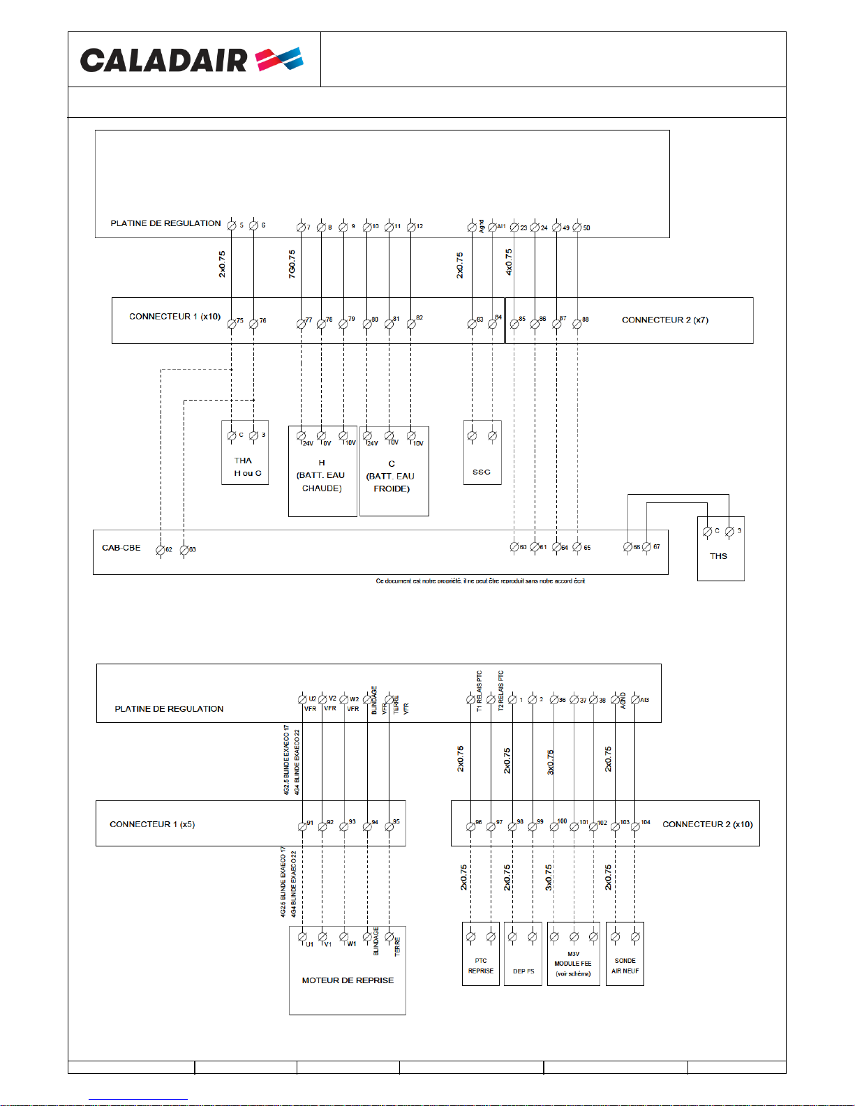
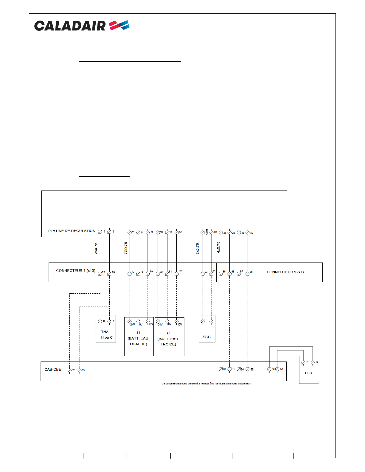
IV.12. Hot water coil intergrated (H) / Changeover water coil (CO) et cold coil C
For units equipped with a cold battery or changeover, the additional module is equipped with a removable stainless
steel condensate tray with integrated siphon. Connection of the PVC pipe diameter 32 to predict.
Connection between the additional module and the B1 junction box to be made.
Pay attention to let the doors free of access (ducts, cables)
In the ELITE and EDEN version, the battery is already installed in the central unit, the Antifreeze Thermostat is connected.
However, you must wire the 3-way valve. If you are using a hot coil battery, also connect the THA (Thermostat Antifreeze)
and remove the supply temperature sensor after the battery
THE VALVE MUST BE CONNECTED OFF
Connect the actuator of the 3-way valve as follows:
Hot Battery :
Terminal 77 of the connector B1 (additional module) on +24V (G) of the actuator
Terminal 78 of the connector B1 (additional module) on 0V (G0) of the actuator
Terminal 79 of the connector B1 (additional module) on 10V (Y) of the actuator
Connect the NC contact (C et 2) of THA (THermostat Antigel) on terminal 75 and 76 of the connector B1 (additional module)
Possibility to connect the hot water circulator to the control unit on the terminals 49 and 50. (Note: 24V output to relay)
Possibility to connect a free voltage contact NO pump fault on the terminals 45 et 46
Cold battery :
Terminal 80 of the connector B1 (additional module) on +24V (G) of the actuator
Terminal 81 of the connector B1 (additional module) on 0V (G0) of the actuator
Terminal 82 of the connector B1 (additional module) on 10V (Y) of the actuator
Connect the NC contact (C et 2) of THA (THermostat Antigel) on terminal 75 and 76 of the connector B1 (additional module)
Possibility to connect the cold water circulator to the control unit on the terminals 63 and 64. (Note: 24V output to relay)
Possibility to connect a free voltage contact NO pump fault on the terminals 45 et 46
Changeover battery :
Red wire of changeover thermostat (CO) on 10V (Y) of the actuator
Terminal 77 of the connector B1 (additional module) on +24V (G) of the actuator
Terminal 78 of the connector B1 (additional module) on 0V (G0) of the actuator
Terminal 79 of the connector B1 (additional module) on brown wire of changeover thermostat (CO)
Terminal 82 of the connector B1 (additional module) on black wire of changeover thermostat (CO)
Connect the NC contact (C et 2) of THA (THermostat Antigel) on terminal 75 and 76 of the connector B1 (additional module)
Possibility to connect the hot water circulator to the control unit on the terminals 49 and 50. (Note: 24V output to relay)
Possibility to connect the cold water circulator to the control unit on the terminals 63 and 64. (Note: 24V output to relay)
Possibility to connect a free voltage contact NO pump fault on the terminals 45 et 46
EXAECO ®
HIGH EFFICIENCY RECOVERY UNIT
OPERATING AND COMMISSIONING INSTRUCTIONS
MS-CDF-002
Ind D
Maj. 02/11/2018
Créé par : JC
Validé par : AR
Page 19/49
IV.13. DX cold coil or changeover DX coil
A condensate connection via a siphon is to be expected.
Possibility of connections :
• 24 V available when the unit is on hot or cold demand.
• 0-10V hot and cold analogue outputs.
Hot demand :
• 24V digital output : To be connected to terminals 71 and 72 and to give the run command to drive a DX module
(Attention 24V 2A Max to relay)
• 0-10V analogue output : To be connected to terminals 8 and 9 (8 = 0V and 9 = 0 / 10V)
Cold demand :
• 24V digital output : To be connected to terminals 73 and 74 and to give the run command to drive a DX module
(Attention 24V 2A Max to relay)
• 0-10V analogue output : To be connected to terminals 11 and 12 (11 = 0V and 12 = 0 / 10V)
WARNING: The 24V and 0-10V operating commands do not manage any safety, anti-short cycle ... direct expansion.
IV.14. Electrical Battery

EXAECO ®
HIGH EFFICIENCY RECOVERY UNIT
OPERATING AND COMMISSIONING INSTRUCTIONS
MS-CDF-002
Ind D
Maj. 02/11/2018
Créé par : JC
Validé par : AR
Page 20/49
IV.15. Fonction incendie
See configuration chapter V.8
There are 2 ways to drive the fire function:
o Emergency Fireman stop: cable between 61 and 62 terminals (NC free voltage contact). Total stop of the central
control. (no display available)
o Fire alarm: this function controls exhaust and return fans with 5 modes available in the parameters of the regulation
(the function can be activated on site). “fire alarm” will be will be on the display.
1. « stop » : complete stop of the unit
2. «continuous work » : Start of the unit in HS, fire function will have priority on all the other alarms.
3. «Normal work» : keeps the unit running with parameters activated on site (Stop/LS/HS)
4. « Supply fan only » : start or keeps in HS the supply fan (extract stopped)
5. « Extract fan only » : starts or keeps in HS the extract fan (supply stopped)
Digital input « external stop » is priority on fire function.
This function is not adapted anymore to the French market and will be in all cases validated by the control office.
Digital input fire alarm will be connected between DI8 terminal of the slave controller and 45 of the terminal block (free
voltage contact required)
IV.16. Raccordement du MODBUS / WEB / BACNET
See configuration chapter V.8
MODBUS RS485 and BACNET MSTP: Use armoured cable 2 crossed pairs wire type BELDEN 8723 or similar to connect
BMS to controller (to connect to port 1 (BANE) / connect armour to N and don’t connect E)
WEB / MODBUS TCP/IP et BACNET IP: to connect to TCP/IP port

EXAECO ®
HIGH EFFICIENCY RECOVERY UNIT
OPERATING AND COMMISSIONING INSTRUCTIONS
MS-CDF-002
Ind D
Maj. 02/11/2018
Créé par : JC
Validé par : AR
Page 21/49
V. SETTINGS
V.1. Display
EXAECO® is delivered in standard with ED9200IP65 display
Once accessed to the emulator settings , you will have access to all function and screens below
o Directional arrows up, down left and right help to navigate in the menus.
o Up and Down buttons help to increase or decrease the values of a parameter when you have access to. Right and left
buttons help to navigate inside the parameter.
o OK button help to enter the value and to confirm a choice. C button helps to cancel it.
o Alarm button (red) allows the access of the defaults list.
o Left arrow also helps to go out of the alarm menu and go back to the main menu
o Cursors indicate the possible movements and which arrows to press.
V.2. Exemple of setting
o Move the cursor to the required menu
In the required menu: press OK
Enter the password if necessary
o Enter the required value with arrows or with numerical keyboard
o Press OK to valid and go to next step.
When values are updated press the left arrow to come back to the welcome screen
Hour : ex : 10:33
Date : ex : 08/12/23 (year/month/day)
Day : ex : Mardi

EXAECO ®
HIGH EFFICIENCY RECOVERY UNIT
OPERATING AND COMMISSIONING INSTRUCTIONS
MS-CDF-002
Ind D
Maj. 02/11/2018
Créé par : JC
Validé par : AR
Page 22/49
V.1. Standard settings (opérator menu)
Words in normal writing = viewing only / Words in bold = Modification is possible / Outlined words in bold=
Modification is possible with password 3333 … = non accessible or not used
ATTENTION : Do not modify parameters which are not in bold characters, in this case no after sales will be
admitted
Regulation mode
Year: month :day Hour
System: state of unit
SP : Setpoint T°C Act : T°C actuelle
CORRIGO E
Battery type
Control type
PG number
Ventilation
Version :
Id number:
Choose language
English (10)
List of the accessible and modifiable main
menus with password 3333.
Humidity regulation menu is only accessible
when unit is in humidity control mode
(10) Language setting (see chapiter V.4.e)
Running mode
Temperature
Ventilation
Timer
Access right

EXAECO ®
HIGH EFFICIENCY RECOVERY UNIT
OPERATING AND COMMISSIONING INSTRUCTIONS
MS-CDF-002
Ind D
Maj. 02/11/2018
Créé par : JC
Validé par : AR
Page 23/49
V.1.a. Menu running mode
(7) Unit Start/Stop (see chapter V.4.e)
(10) Language setting (see chapiter V.4.f)
Running mode
Regulation mode
Year: month :day Hour
System: state of unit
SP : Setpoint T°C Act : T°C actuelle
CORRIGO E
Battery type
Control type
PG number
Ventilation
Version :
Id number:
Running mode
…
Running mode
Auto (7)
Running time
Vent.SAF: 00.0 H
Viewing the history alarms (use the
down arrow to scroll through the
history)
Alarm report
Input/Output
...
AI Ext1
(Analogue Input)
AI1: T° AS (suuply)
AI2: T° Ext (outdoor)
AI3: T° AR (extract)
AI4: CO2
DI
(Digital input)
DI1: Recirculation
DI2:
DI3: Rotative exchanger
default
UI Ext1
(Universal Input)
UAI1: Press AS
(LOBBY / MAC2 et QUATTRO)
UAI2: Press AR
(LOBBY / MAC2 et QUATTRO
...
UDI1: Start VAS
UDI2: Start VAR
...
Running time
Vent.EAF: 00.0 H
DI Ext1
(Digital Input)
DI1: Al Filter1
DI2: Al Filter2
DI3: Over heat
ou External frost guard
DI4: Ext 1/2
DI5: Ext 1/1
DI6: Ext stop
DI7: P1 Heat
Choose language
English (10)

EXAECO ®
HIGH EFFICIENCY RECOVERY UNIT
OPERATING AND COMMISSIONING INSTRUCTIONS
MS-CDF-002
Ind D
Maj. 02/11/2018
Créé par : JC
Validé par : AR
Page 24/49
V.1.b. Temperature menu
(8) Temperature setpoint setting (see chapter V.4.d)
AO
(analogue outputs)
Input/Output
Running mode
AO1: Y4 S-Suppl
(0V = recycling)
(10V = Fresh air)
...
DO
(Digital output)
DO1: Reg. AN
DO2: Reg. Recy
DO3: Heat demand
DO4: Cool demand
AO1: Y1 Heating.
AO2: Y2 Exchang.
AO3: Y3 Cool
AO4: Ctrl SAF
AO5: Ctrl EAF
AO Ext1
(analogue outputs)
DO1: V.freq SAF
DO2: V freq EAF
DO3: Rot exch. activ.
DO4: Heat Pump
DO5: Cool pump.
DO6: Surventil.activ
DO7: Somme alarme
DO Ext1
(Digital output)
Temperature.
Extract Temperature
Real:
Setpoint : 21°C (8)
...
Setpoint comp ext
-20°C = 25°C (8)
-15°C = 24°C (8)
-10°C = 23°C (8)
Consigne comp ext
-5°C = 23°C (8)
0°C = 22°C (8)
5°C = 20°C (8)
Setpoint comp ext
10°C = 18°C (8)
15°C = 18°C (8)
Outdoor temp :
Supply temp
Real : Cons
Setpoint :

EXAECO ®
HIGH EFFICIENCY RECOVERY UNIT
OPERATING AND COMMISSIONING INSTRUCTIONS
MS-CDF-002
Ind D
Maj. 02/11/2018
Créé par : JC
Validé par : AR
Page 25/49
V.1.c. Ventilation menu
(5) Speeds, pressures, airflows (see chapter V.4.b)
(6) CO2 setpoint except DIVA and QUATTRO (voir chapitre V.4.c)
Ventilation
Frequency control SAF
(STANDARD OU DIVA)
Output: 70 (5) %
or
Pressure Control SAF
(LOBBY)
Real : 183Pa (example)
Setpoint : 180 Pa(5)
or
Air flow SAF
(MAC2 QUATTRO)
Real : 1503m3/h (example)
Setpoint : 1500m3/h(5)
Frequency control SAF
Sp 1/1: 70% (5)
Sp 1/2: 50% (5)
...
CO2 (except DIVA® OU QUATTRO® )
Réal : 654ppm (exemple)
Setpoint : 1000ppm (6)
Pressure Control SAF
Sp 1/1: non utilisé
Sp 1/2: 180Pa (5)
...
Air flow SAF
Sp 1/1: 5000m3/h (5)
Sp 1/2: 2500m3/h (5)
...
Frequency control EAF
(STANDARD OU DIVA)
Output: 70 (5) %
or
Pressure Control EAF
(LOBBY)
Real : 183Pa (example)
Setpoint : 180 Pa(5)
or
Air flow EAF
(MAC2 QUATTRO)
Real : 1503m3/h (example)
Setpoint : 1500m3/h(5)
Pressure Control SAF
Sp 1/1: non utilisé
Sp 1/2: 180Pa (5)
...
Contrôle pression VAR
Cons 1/1: non utilisé
Cons 1/2: 180Pa (5)
...
Air flow SAF
Sp 1/1: 5000m3/h (5)
Sp 1/2: 2500m3/h (5)
...

EXAECO ®
HIGH EFFICIENCY RECOVERY UNIT
OPERATING AND COMMISSIONING INSTRUCTIONS
MS-CDF-002
Ind D
Maj. 02/11/2018
Créé par : JC
Validé par : AR
Page 26/49
V.1.d. Timer menu
1. Hour and date setting (see chapter V.4.a)
2. HS program setting (see chapter V.4.a)
3. LS program setting (see chapter V.4.a)
4. Holidays period setting (see chapter V.4.a)
9. Holidays period setting (see chapter V.4.a)
Timer normal speed
Normal speed
Monday (2)
Per 1 : 07:00 - 22:00
Per 2 : 00:00 - 00:00
Normal speed
Monday - Friday (2)
Per 1 : 07:00 - 22:00
Per 2 : 00:00 - 00:00
Normal speed
Tuesday (2)
Per 1 : 07:00 - 22:00
Per 2 : 00:00 - 00:00
Etc…until sunday + holidays
Timer
Hour / Date
Hour : 15:54 (1)
Date : 2011-01-25 (1)
Day : Tuesday (1)
Timer reduced speed
Slow speed
Monday (3)
Per 1 : 00:00 - 05:00
Per 2 : 22:00 - 24:00
Slow speed
Monday - Friday (3)
Per 1 : 00:00 - 05:00
Per 2 : 22:00 - 24:00
Slow speed
Tuesday (3)
Per 1 : 00:00 - 05:00
Per 2 : 22:00 - 24:00
Etc…until sunday + holidays
Holydays (mm:jj) until 24 periods (4)
1: 01-01 - 01:01 (example 1er Janvier)
2: 12-25 - 12:25 (example 25 décembre)
Holidays
Access rights
Entrer
Exit
Enter password of the autorisation level
required : ****
Current level:
Exit this autorisation level ? NO or YES
Current level
Timer 5
Tuesday (9)
Per 1 : 05:00 - 07:00
Per 2 : 00:00 - 00:00
Etc…until sunday + holidays
Timer 5
(Timer to star up
RECIRCULATION)

EXAECO ®
HIGH EFFICIENCY RECOVERY UNIT
OPERATING AND COMMISSIONING INSTRUCTIONS
MS-CDF-002
Ind D
Maj. 02/11/2018
Créé par : JC
Validé par : AR
Page 27/49
V.2. Operator parameters modification ( password 3333 required)
V.2.a. Dates and hours clocks setting
V.2.a.1. Date and hour of the CORRIGO controller [(1) chapter V.3.d]
Access : Hour Date setting
Date and hour of the regulator are set by defaut in the CORRIGO controller. Summer/Winter time is automatically managed.
V.2.a.2. Hour programmation of the functionning system [(2) (3) chapter V.3.d]
Access :
o Timer normal speed : Time settings / normal speed program
o Timer reduced speed : Time settings / slow speed program
o Timer recirculation : Time settings / Timer 5
System is set to work in normal speed (HS-1/1) 07:00 - 22:00 in slow speed (LS-1/2) 22:00 - 06:00 except DIVA / LOBBY /
QUATTRO versions which work in slow speed (LS-1/2)
As indicated in arborescence you also have the possibility to modify Monday to Friday periods by pressing the right button
when you are on the Monday screen
Nota : if slow speed (LS-1/2) and normal speed (HS-1/1) are activated in the same time window, unit works in high speed
Operation exceptions:
DIVA®/QUATTRO® : For CO2 regulation do not activate any normal speed time window (GV-1/1)
o LOBBY: Only slow speed clock (LS-1/2) must be activated
o NIGHT COOLING: Only works if unit is in slow speed (LS-1/1) between 00:00 and 07:00.AM
(Example: If unit is in (LS-1/2) between 02:00 and 06:00 and in (HS-1/1) the rest of the time. Then NIGHT
COOLING is allowed to work only from 02:00 to 06:00 AM)
V.2.a.3. Holidays periods [(4) chapter V.3.d]
Access : Time settings / Holidays
The system is set without vacation period. In case you wish to reduce the operating time during holiday periods, set the holiday
operating hours as described in chapter V.3.4), then set your holiday days.Modification de la vitesse / pression en PV et GV
V.2.a.4. ECO / DIVA® / [(5) chapitre V.3.c]
Access : ventilation Regul / Frequency control VAS 1/1 and 1/2 or frequency control VAR 1/1 et 1/2
You can modify the rotation speed of the unit in PV-1/2 (slow speed) and in HS-1/1 (normal speed) for each fan to set the
airflows.
o To set the initial airflow (GV-1/1), force the system in normal speed with available terminals « Forced start HS »
(bridge between 41 and 42 terminals).
o To set the initial airflow LS, force the system in slow speed with available terminals « Forced start LS » (bridge
between 39 and 40 terminals).
V.2.a.5. LOBBY® [(5) chapitre V.3.c]
Access : ventilation Regul / Pressure control VAS 1/2 or Pressure control VAR 1/2
You can modify the constant pressure of the unit for each fan to set the airflows.
o To set the initial airflows LS, force the le system in normal speed with available terminals « Forced start LS » »
(bridge between 39 and 40 terminals).
V.2.a.6. MAC2®/QUATTRO® [(5) chapitre V.3.c]
Access : ventilation Regul / Airflow control VAS 1/1 and 1/2 or Airflow control VAR 1/1 and 1/2
You can modify the rotation speed of the unit in PV-1/2 (slow speed) and in HS-1/1 (normal speed) for each fan to set the
airflows.
o To set the initial airflow (GV-1/1), force the system in normal speed with available terminals « Forced start HS »
(bridge between 41 and 42 terminals).
o To set the initial airflow LS, force the system in slow speed with available terminals « Forced start LS » (bridge
between 39 and 40 terminals).

EXAECO ®
HIGH EFFICIENCY RECOVERY UNIT
OPERATING AND COMMISSIONING INSTRUCTIONS
MS-CDF-002
Ind D
Maj. 02/11/2018
Créé par : JC
Validé par : AR
Page 28/49
V.2.b. CO2 setpoint modification for three ways mixing damper (FEE) (except DIVA et
QUATTRO)
[(6) chapitre V.3.c]
Access : CO2
You can modify the CO2 setpoint. (1000ppm in standard)
V.2.c. Temperature setpoint modification
[(8) chapitre V.3.b]
Access : temperature Regul
Regulation is based on the temperature control of :
o Supply with external compensation (set in standard). Supply temperature setpoint follows outside temperature in
compliance with RT 2012 norm.
o Extract
V.2.d. Forced stop of the unit or forced start LS or HS on the remote control
[(7) chapter V.3.a]
Access : running Mode / running Mode
You can stop (7) (stop) unit with CORRIGO controller or do a forced start LS (7) (manual speed 1/2) or HS (7) (manual
speed 1/1). In standard unit works automatically with clocks (7) (Auto)
If unit do not work in automatic mode an alarm will start. Manual speed 1/1 and manual speed 1/2 modes must be used
only for the commissioning and repair. An other setting will lead to a failure of the unit.
V.2.a. Choice of language
[(10) chapter V.3]
Access: Starting screen / language choice
V.3. Intermediate settings (service level)
Type of regulation type setting, Night Cooling parameters and CO2 setpoint require an acess to the Configuration menu.
You need the access right to the « Service » level. Follow the instrcuctions below.
Enter 2222 with directional arrows and validate with OK. Press left arrow twice to reach the access of the menus. In case of
mistake press C button twice and start again.
Access right
Enter
Enter password 2222 of the
required level :
Current level : SERVICE

EXAECO ®
HIGH EFFICIENCY RECOVERY UNIT
OPERATING AND COMMISSIONING INSTRUCTIONS
MS-CDF-002
Ind D
Maj. 02/11/2018
Créé par : JC
Validé par : AR
Page 29/49
V.3.a. Menu configuration en accès service
V.4. Modification of the services parameters (password 2222)
V.4.a. Regulation mode of the unit [(1) chapter V.3.a]
Access : Configuration / Regulation function.
Regulation type is set by default in the CORRIGO controller in outside compensation exhaust. You can also select return
control mode.
(ATTENTION, if you want to regulate following a room temperature, select the regulation mode« Ctrl extract » Any
other mode will lead to the failure of the unit)
V.4.b. Overventilation parameters [(2) chapter V.3.a]
Access : Configuration / Night cooling
Night cooling speed is set in standard in 85%. You can modify it. You can also change the temperature of Night Cooling
activation (outside temperature day…) and deactivate it.
V.4.c. CO2 setpoint for DIVA / QUATTRO option [(3) Chapter V.3.a]
Access: Configuration / Ctrl CO2/COV
CO2 setpoint is set in standard: LS = 800ppm HS = 1000ppm. Unit will increase its speed proportionally to reach its maximum
speed when CO2 will be at 1000ppm.
V.4.d. Minimum opening percentage of the 3 ways mixing damper (FEE) [(4) chapitre V.3.a]
Accés : Configuration / Ctrl CO2/COV
En standard à 30% d’ouverture soit 10% d’air neuf – Voir courbe de correspondance chapitre VIII.5
Configuration
Regulation Function
Night Cooling
Ctrl CO2/VO
Lim Mini damper
Regulation Function
Mode:
Supply t+comp ext (1)
Night cooling activated : YES (2)
Outdoor temp activation : 22°C (2)
Outdoor T° night
High 18°C (2)
Low 10°C (2)
Room mini Temp: 18°C (2)
Speed : 85%
Ctl CO2/COV activated :
If timer ON
Type : Fans
Speed 1/2 : 800 ppm (3)
Speed 1/1 : 1000 ppm (3)
Diff : 160ppm
1. Regulation type choice (see chapter V.6.a)
2. Parameters modification Night Cooling (see chapter V.6.b)
3. CO2 set point modification (only in DIVA and QUATTRO) (see chapter V.6.c)
4. Limit mini damper (except DIVA et QUATTRO) (see chapter V.6.D)
Lim. Mini damper
Active
Limit min : 30% (4)
except DIVA MAC2

EXAECO ®
HIGH EFFICIENCY RECOVERY UNIT
OPERATING AND COMMISSIONING INSTRUCTIONS
MS-CDF-002
Ind D
Maj. 02/11/2018
Créé par : JC
Validé par : AR
Page 30/49
V.5. Administrator settings
Activation of the communication, dehumidification and fire function requires an access to Configuration menu in system
level. You have to get the access rights to « Admin » level. Follow the instructions below:
Enter 1111 with directionnal arrows and validate with OK button. Press left arrow twice to reach the menu. In case of mistake
press C button twice and start again
V.5.a. Configuration menu with admin level access
Access rights
Enter
Enter password 1111
Of the required autoris.
Current level : ADMIN
Configuration
Communication
Système
Port 1
Esclave
1 et 2 Activation MODBUS RS485 and settings (see chapter V.6)
3 et 4 Activation BACNET MSTP and settings (see chapter V.6)
5 et 6 Settings TCP/IP(see chapter V.6)
7 et 8 Activation du BACNET IP and settings (see chapter V.6)
9 Adressage Repetiteur (voir chapitre V.6)
Communication
Modbus esclave
Port 1
Active (1)
Device name : - (4)
Mac : 0 (4)
Id appareil Bas : 2640 (4)
Id appareil Haut : 0 (4)
(x10000)
Vitesse : 9600 Bps(4)
Ad. maître max : 127 (4)
Adresse Modbus : 1 (2)
Vitesse : 9600 Bps (2)
2 bits d’arrêt : Oui (2)
Parité Non (2)
Adresses
PLA : 254 (9)
ELA : 254 (9)
Communication
Bacnet MSTP
Port 1
Active (3)
TCP/IP
IP : - (6)
Subnet Mask - (6)
Subnet Mask - (6)
Gateway - (6)
DHCP : OUI (5)
Ip actuel :
Communication
Bacnet IP
Active (7)
Device name : - (8)
Adresse BBMD : 0 (8)
Id appareil Bas : 2640 (8)
Id appareil Haut : 0 (8)
(x10000)
N° port UDP bas 7808(8)
N° port UDP haut 4(8)
(x10000)

EXAECO ®
HIGH EFFICIENCY RECOVERY UNIT
OPERATING AND COMMISSIONING INSTRUCTIONS
MS-CDF-002
Ind D
Maj. 02/11/2018
Créé par : JC
Validé par : AR
Page 31/49
V.6. Modification of the service parameters
V.6.a. MODBUS
You will find the simplified MODBUS at the end of the instructions and commissioning manual.
Access : Configuration / Communication
MODBUS TCP/IP is activate in standard in DHCP. Possibility to know DHCP adress or set IP fixe [(5)(6) chapter V.7],
Modbus Port = 502 / Device ID = 255
Le MODBUS RS 485 must be activate [(1) chapitre V.7]. Possibility to set speed, parity, stop bits… [(2) chapter V.7].
Modbus Type
1 = Coil status register (Modus fonction 1, 5 et 15)
2 = Input status register (Modus fonction 2)
3 = Holding register (Modus fonction 3, 6 et 16)
4 = Input resister (Modus fonction 4)
Supported Modbus functions
Read Coils (1)
Read discrete input (2)
Read Holding registers (3)
Read Input registers (4)
Write single Coils (5)
Write single register (6)
Write multiple Coils (15)
Write multiple register (16)
EXOL Type
R = Real (-3.3E38 – 3.3E38)
I = Integer (-32768 – 32767)
X = Index (0 – 255)
L = Logic (0/1)
Transmission mode
Controller is set in RTU mode
A maximum of 47 registers can be read in one message
V.6.b. Communication WEB
You have the possibility to communicate via TCP/IP WEB in language. In this case the device is delivered with Web page and
regulator set in DHCP.
Possibility to know DHCP adress or set IP fixe [(5)(6) chapter V.7], or via E-tool software http://www.regin.se

EXAECO ®
HIGH EFFICIENCY RECOVERY UNIT
OPERATING AND COMMISSIONING INSTRUCTIONS
MS-CDF-002
Ind D
Maj. 02/11/2018
Créé par : JC
Validé par : AR
Page 32/49
V.6.c. BACNET
You will find the simplified BACNET at the end of the instructions and commissioning manual.
Accès : Configuration / Communication
BACNET IP must be activate [(7) chapter V.7]. Possibility to know DHCP adress or set IP fixe [(5)(6) chapter V.7].
Possibility to set ID / N°port… [(8) chapter V.7].
BACNET MSTP must be activate [(3) chapter V.7]. Possibility to set speed, ID, adress… [(4) chapter V.7]. Speed = 9600 /
MAC adress = 0 / Device ID = 2640 / Max master = 127
BACnet Type
10XXX = Read and write Binary
20XXX = Read binary
30XXX = Read and write analogue
40XXX = Read analogue
30XXX = Read and write multistate
40XXX = Read multistate
(XXX = MODBUS Adress)
AV = Analogue Value
BV = Binary Value
MSV = Multistate value
BMMD Adress : The BBMD adress is used for discovering devices taht are attached to different BACnet/IP subnets and
separates by an IP router. The address is entered as host:host can be the host’s name if DNS ins configures. If DNS is not
configured, the host address should be entered in the format xxx.xxx.xxx.xxx follwed by the port number (default settings
47808)
MAC : The MAC address of the device. This need to be unique only to the subnet.
Device ID : The ID of a device, used to identify it on the BACnet network. This number cannot be duplicated anywhere on the
BACnet network and must therefore be unique. To set an ID value of 34600, the low number would be set to 4600 and the high
number to 3
For more information see CORRIGO Pics via http://www.regin.se
V.6.d. Fire funtion activation
Setting of the Paramétrage de l’entrée
Access : Configuration / Input Output / DI ext / DI8
Déclarer l’input DI ext 8 en « Al fire » « NO »
Paramétrage de la fonction
Access : Configuration / Fire function
Choose the required mode when activating the fire function
« Stop » : Complete stop of the unit
«Continuous operation »: Start or keeping of the unit in HS. Fire function will have priority on all others alarms.
«Normal operation»: keeps the unit in the same parameters chosen on site (stop/LS/HS)
« Exhaust fan only »: Start or keep in HS the exhaust fan (return is stopped)
« Return fan only »: Start or keeps in HS the return fan (exhaust stopped)
Alarm setting
Access: Configuration / alarm configuration
Enter alarm number « 10 » go on the right and enter in priority « C alarm C » « Active »

EXAECO ®
HIGH EFFICIENCY RECOVERY UNIT
OPERATING AND COMMISSIONING INSTRUCTIONS
MS-CDF-002
Ind D
Maj. 02/11/2018
Créé par : JC
Validé par : AR
Page 33/49
VI. REPAIR
VI.1. Different types of defaults
EASY control units are equipped with alarms. When the red LED flashes, press the alarm key (red) to display the fault. This
one will be class A, or C (see details below)
Type of defect:
A: The fault stops the ventilation system. The unit will not start until the problem has been solved and the fault has been
acknowledged.
C: The fault does not stop the ventilation system and disappears automatically as soon as the problem has been solved.
To acknowledge a fault press the alarm button (red), "cancel" and then "save" the fault using the arrows and the OK key. Be
careful not to "block"
Description
Cause
CORRIGO screen do not light up
- Unit is not powered correctly (LED P/B of CORRIGO switched off)
- To light up the screen, press a button (backlit).
- Command fuse is disused
Fans do not start
- Clocks are on 0
- No external start order
- External stop
- Active alarm
Remote control do not run
or gives wrong values
Remote control further than 100m
Repetitor is not connected correctly
VI.2. List of alarms
n°
Affichage
Description
Type
Tempo
Cause
1
Malfunction
supply air fan
(Ext UDI1 must be
closed « on »if fan
runs)
Or
Ext UAI1 must be
higher than 30Pa if
fan runs )
A
30s (120s
for
LOBBY)
1. Pressure switch is wrongly connected (pressure
switch must be set in 30Pa).
2. Pressure on the transmittor is lower to 30Pa.
(LOBBY®) (contact us)
3. Motor is disused
4. Thermic protection motor is activated
5. Check the connection of the crystal tubes (Chapter
IV.7 and IV.8
6. Presence of water in the crystal tube
7. 0-10V motor is inverted
1
Malfunction
extract air fan
(Ext UDI2 must be
closed « on »if fan
runs)
Or
Ext UAI2 must be
higher than 30Pa if
fan runs )
A
30s (120s
for
LOBBY)
1. Pressure switch is wrongly connected (pressure
switch must be set in 30Pa).
2. Pressure on the transmittor is lower to 30Pa.
(LOBBY®) (contact us)
3. Motor is disused
4. Thermic protection motor is activated
5. Check the connection of the crystal tubes (Chapter
IV.7 and IV.8
6. Presence of water in the crystal tube
7. 0-10V motor is inverted
3
Pump fault
Ext DI7 mus be
open « off » if there
is no fault
C
0s
The circulator fault contact is closed

EXAECO ®
HIGH EFFICIENCY RECOVERY UNIT
OPERATING AND COMMISSIONING INSTRUCTIONS
MS-CDF-002
Ind D
Maj. 02/11/2018
Créé par : JC
Validé par : AR
Page 34/49
6
Filter guard 1
Ext DI1 must be
open « off » if there
is no default
C
5s
1. Filters are dirty
2. Filters pressure switches are wrongly connected
(Pressure switches must be set on 150 Pa for G4
200Pa for F7).
8. Control the connection of the crystal tubes (chapter
IV.6
8
External frost
guard
Ext DI3 must be
closed « Fer »if
there is not default
C
120s
1. THA thermostat is not set on 5°C
2. THA thermostat s disused
3. Circulating pump is disused
4. 3 ways valve 3 is wrongly connected, hydraulically
or is disused
15
High supply air
temp
Ext AI1 is mounted
higher than 50°C
A
30s
1. Exhaust temperature is higher than 50°C
2. Temperature setting is too high
3. Exhaust fan is stopped (vent
AS Default) when hot battery is in full capacity.
23
Electric heating
is overheated
Ext DI3 must be
closed « Fer » if
there is no default
A
5s
1. Safety thermostat THS is activated. To reset THS,
push on the rearmament on the electric battery
2. Power cut
3. Exhaust fan is stopped (vent
AS Default) when electric battery is in full capacity
27
Sensor error
outdoor temp
Control the value
Ext AI2
A
5s
Outside temperature sensor SEG is disused .Outside
temperature sensor SEG is wrongly connected (see chapter
IV.3)
29
Rotation sentinel
exchanger
Control the value
DI6
C
300s
The belt of the exchanger is brocken
31
Supply air fan
control error
Difference higher
than 50Pa between
exhaust setpoint
and pressure on
Ext UAI1
C
30min
The network of blowing do not correspond to the fan or
to the setpoint.
Filter is dirty
32
Extract air fan
control error
Difference higher
than 50Pa between
exhaust setpoint
and pressure on
Ext UAI2
C
30min
Return network do not correspond to the fan or to the
setpoint.
Filter is dirty
35
Manual
Runs in manual
mode
C
5s
Default à titre indicatif (le centrale est passée à l’arrêt en PV
ou en GV directement sur l’afficheur (voir (7) chapitre V.3.a)
36 à
44
… in Manual
mode
Functions are
modified in
manual mode
C
5s
In the Auto Manual menu everything must be in Auto.
48
Internal battery
error
Error battery intern
A
5s
Intern battery of the CORRIGO is disused
Change the battery quickly in order to not loose programm.
See chapter VII.2
49
Sensor error
supply air temp
Control the
Value on Ext AI1
A
5s
Outside temperature sensor SSG is disused
Outside temperature sensor SSG is wrongly connected (see
chapter V.3.a)
50
Sensor error
extract air temp
Contrôler la
valeur sur Ext AI3
A
5s
Outside temperature sensor SRG is disused
Outside temperature sensor SRG is wrongly connected (see
chapter V.3.a)
55
Sensor error
pressure VAS
Control the value
on Ext UAI1
A
5s
0-10V signal is inverted
Pressure transmittor on fresh air is in short-circuit

EXAECO ®
HIGH EFFICIENCY RECOVERY UNIT
OPERATING AND COMMISSIONING INSTRUCTIONS
MS-CDF-002
Ind D
Maj. 02/11/2018
Créé par : JC
Validé par : AR
Page 35/49
56
Sensor error
extract VAR
Control the value
on Ext UAI2
A
5s
0-10V signal is inverted
Pressure transmittor on intake air is short circuited
59
CO2 sensor error
Control the
Value on Ext AI4
A
5s
0-10V signal is inverted
CO2 transmittor is in short-circuit
85
… in manual
mode
Functions are
modified in
manual mode
A
5s
In Manuel Auto menu everything must be in Auto.
86
Time for service
Regular visit
C
5s
See chapter VI.3
87
… in manual
mode
Functions are
modified in
manual mode
C
5s
In Manuel Auto menu everything must be in Auto.
VI.3. Acknowledge the default « timer service »
These settings require an access to the setting menu. You need the access rights to “service” level. Follow the instructions
below.
Enter the code 2222 with directional arrows then press the OK button. Press the left arrow twice to reach the menus. In case of
mistake press C button twice and start again.
An alarm occurs every 6 months to remind the maintenance visit. Enter YES to reset the counter to zero
Settings
Reset to zero
Filters counter
filter alarm
Reset to zero of the
Timer : YES
access rights
Enter
Enter password 2222
Of the required autoris. level:
Current level : SERVICE

EXAECO ®
HIGH EFFICIENCY RECOVERY UNIT
OPERATING AND COMMISSIONING INSTRUCTIONS
MS-CDF-002
Ind D
Maj. 02/11/2018
Créé par : JC
Validé par : AR
Page 36/49
VII. MAINTENANCE
VII.1. Mandatory maintenance
Outside the unit
Check the ducts, flexible sleeves, anti-vibrating plots; replace them if necessary. Check that all elements connected to the unit
do not give any vibration to the unit.
Unit and Regulation
Check connection every year
Filtration
Do not damage the filters
Classification
Max pressure drop
Efficency of the
filtration
EUROVENT
Reference
Washing*
(Water + light detergent )
Aspiration*
Exhaust*
Gravimetric
150Pa
EU4
G4
Limited (1 to 4 times)
YES
Opacimetric
200Pa
EU7
F7
NO
Periodicity of the cleaning
Componants
1 MONTH
3 MONTHS
6 MONTHS
12 MONTHS
Filtration
Blowing
(for the G4filters)
Cleaning
(for the G4filters)
Washing
(for the G4filters )
Replacement
Of the filters if needed
Rotative exchanger (12 month)
Check belt and change it if necessary
VII.2. Battery replacement
When low battery alarm starts and red LED is lighting, this indicates that the safety battery for the safeguard of the memory
and clock is too low. Follow the instructions below to change them. A condenser keeps the safeguard and let the clock running
for 10 minutes left after power cut. If the replacement of the battery takes less than 10 minutes, you will not have to reset the
program and clock will work normally.
Replacement battety is a CR2032 type
Press the clips on each sides of the box with a little screwdriver to open the the top of the box.

EXAECO ®
HIGH EFFICIENCY RECOVERY UNIT
OPERATING AND COMMISSIONING INSTRUCTIONS
MS-CDF-002
Ind D
Maj. 02/11/2018
Créé par : JC
Validé par : AR
Page 37/49
Location of the battery
Saisir la pile et tirer doucement vers le haut jusqu’à ce que la pile quitte son logement.
Appuyer fermement sur la pile neuve pour la glisser dans le support. Note : Attention au sens de la pile pour bien respecter la
polarité.

EXAECO ®
HIGH EFFICIENCY RECOVERY UNIT
OPERATING AND COMMISSIONING INSTRUCTIONS
MS-CDF-002
Ind D
Maj. 02/11/2018
Créé par : JC
Validé par : AR
Page 38/49
VIII. ANNEXES
VIII.1. Power diagram EXAECO 10

EXAECO ®
HIGH EFFICIENCY RECOVERY UNIT
OPERATING AND COMMISSIONING INSTRUCTIONS
MS-CDF-002
Ind D
Maj. 02/11/2018
Créé par : JC
Validé par : AR
Page 39/49
VIII.2. Power diagram EXAECO 13-22

EXAECO ®
HIGH EFFICIENCY RECOVERY UNIT
OPERATING AND COMMISSIONING INSTRUCTIONS
MS-CDF-002
Ind D
Maj. 02/11/2018
Créé par : JC
Validé par : AR
Page 40/49
VIII.3. Control diagram

EXAECO ®
HIGH EFFICIENCY RECOVERY UNIT
OPERATING AND COMMISSIONING INSTRUCTIONS
MS-CDF-002
Ind D
Maj. 02/11/2018
Créé par : JC
Validé par : AR
Page 41/49

EXAECO ®
HIGH EFFICIENCY RECOVERY UNIT
OPERATING AND COMMISSIONING INSTRUCTIONS
MS-CDF-002
Ind D
Maj. 02/11/2018
Créé par : JC
Validé par : AR
Page 42/49
VIII.4. Motors wiring

EXAECO ®
HIGH EFFICIENCY RECOVERY UNIT
OPERATING AND COMMISSIONING INSTRUCTIONS
MS-CDF-002
Ind D
Maj. 02/11/2018
Créé par : JC
Validé par : AR
Page 43/49
VIII.5. Aeraulics diagram
VIII.5.a. EXAECO 10
VIII.5.b. EXAECO 13

EXAECO ®
HIGH EFFICIENCY RECOVERY UNIT
OPERATING AND COMMISSIONING INSTRUCTIONS
MS-CDF-002
Ind D
Maj. 02/11/2018
Créé par : JC
Validé par : AR
Page 44/49
VIII.5.c. EXAECO 17
VIII.5.d. EXAECO 22

EXAECO ®
HIGH EFFICIENCY RECOVERY UNIT
OPERATING AND COMMISSIONING INSTRUCTIONS
MS-CDF-002
Ind D
Maj. 02/11/2018
Créé par : JC
Validé par : AR
Page 45/49
VIII.5.e. Opening percentage curve of the FEE module
ouvert
fermé
In Standard the minimum% opening of the RMR and RMS registers is 30% or about
15% fresh air flow
100% opening of RMS fresh air and return air registers RMR =
output AO1 = 0V = all fresh air
0% opening of RMS fresh air and return air registers RMR =
output AO1 = 10V = all recycling
30% opening of RMS fresh air and return air registers RMR =
output AO1 = 7V = mixture

EXAECO ®
HIGH EFFICIENCY RECOVERY UNIT
OPERATING AND COMMISSIONING INSTRUCTIONS
MS-CDF-002
Ind D
Maj. 02/11/2018
Créé par : JC
Validé par : AR
Page 46/49
VIII.6. MODBUS register table
INPUT REGISTER
Fonction
Description
Exo
type
Modbus
Adresse
Défaut
value
Unit XXXXX
Modbus :
0= stop
1= start
2= start Slow speed
3= start maxi speed
4= start normal speed
5= In operation
8= CO2 functionning
9= Night cooling
11= stopped
BACNET :
1= stop
2= start
3= start Slow speed
4= start speed maxi
5= start normal speed
6= In operation
9= CO2 functionning
10= Night cooling
12= stopped
X
30003
Outdoor Temperature
R 30001
Operating time of the supply fan
R 30004
Operating time of the extract fan
R 30005
Supply air Temperature
R 30007
Extract Temperature
R 30009
SAF pressure
LOBBY®
R
30013
EAF pressure
LOBBY®
R
30014
Supply constant air flow
MAC2®/QUATTRO®
R
30015
Extract constant air flow
MAC2®/QUATTRO®
R
30016
CO2
DIVA®
R
30017
Analog output
0-10V Module FEE (3 voies)
R
30054
Analog output
0-10V Heating (Hot water coil)
R
30238
Analog output
0-10V Exchanger
R
30239
Analog output
0-10V Cooling
R
30240
Analog output
0-10V Supply air fan
R
30241
Analog output
0-10V Extract air fan
R
30242

EXAECO ®
HIGH EFFICIENCY RECOVERY UNIT
OPERATING AND COMMISSIONING INSTRUCTIONS
MS-CDF-002
Ind D
Maj. 02/11/2018
Créé par : JC
Validé par : AR
Page 47/49
HOLDING REGISTER
Fonction
Description
Exo
type
Modbus
Adresse
Défaut
value
Supply setpoint
Set in constant supply
R
40001
18
Supply setpoint
Set in constant supply comp ext for T°C out –20°C
R
40010
25
Supply setpoint
Set in constant supply comp ext for T°C out de –15°C
R
40011
24
Supply setpoint
Set in constant supply comp ext for T°C out de –10°C
R
40012
23
Supply setpoint
Set in constant supply comp ext for T°C out de –5°C
R
40013
23
Supply setpoint
Set in constant supply comp ext for T°C out de –0°C
R
40014
22
Supply setpoint
Set in constant supply comp ext for T°C out de +5°C
R
40015
20
Supply setpoint
Set in constant supply comp ext for T°C out de +10°C
R
40016
18
Supply setpoint
Set in constant supply comp ext for T°C out de +15°C
R
40017
18
Return setpoint
Set in return control
R
40018
21
speed supply HS setpoint
In % for ECO and DIVA
R
40424
70
speed supply LS setpoint
In % for ECO and DIVA
R
40425
50
speed return HS setpoint
In % for ECO and DIVA
R
40426
70
speed return LS setpoint
In % for ECO and DIVA
R
40427
50
pressure soufflage setpoint
In Pa for LOBBY
R
40025
150
pressure reprise setpoint
In Pa for LOBBY
R
40027
150
Airflow supply HS setpoint
In m3/h for MAC2® and QUATTRO®
R
40028
xxx
Airflow supply LS setpoint
In m3/h for MAC2® and QUATTRO®
R
40029
xxx
Airflow return HS setpoint
In m3/h for MAC2® and QUATTRO®
R
40030
xxx
Airflow return LS setpoint
In m3/h for MAC2® and QUATTRO®
R
40031
xxx
Forçed
Functionning mode of the unit
MODBUS
0= Manual stop
1= Manual slow speed
2= Vitesse normale manuelle
3= Auto
BACNET
1= manual stop
2= Manual slow speed
3= Normal manual speed
4= Auto
X
40368
xx:xx

EXAECO ®
HIGH EFFICIENCY RECOVERY UNIT
OPERATING AND COMMISSIONING INSTRUCTIONS
MS-CDF-002
Ind D
Maj. 02/11/2018
Créé par : JC
Validé par : AR
Page 48/49
INPUT STATUT REGISTER
Fonction
Description
Exo
type
Modbus
Adresse
Défaut
value
Alarm synthesis
If 1 = ALARM
L
10163
SAF default
If 1 = ALARM
L
10033
EAF default
If 1 = ALARM
L
10034
Filter default
If 1 = ALARM
L
10038
Antifreeze default
If 1 = ALARM
L
10040
Fire default
If 1 = ALARM
L
10042
Electric battery overheat
If 1 = ALARM
L
10055
Outdoor temperature default
If 1 = ALARM
L
10059
Battery default
If 1 = ALARM
L
10080
Supply temperature default
If 1 = ALARM
L
10090
Extract temperature Default
If 1 = ALARM
L
10091

EXAECO ®
HIGH EFFICIENCY RECOVERY UNIT
OPERATING AND COMMISSIONING INSTRUCTIONS
MS-CDF-002
Ind D
Maj. 02/11/2018
Créé par : JC
Validé par : AR
Page 49/49
IX. NOTES
 Loading...