

CAIRE Breeze Oxygen Concentrator, Breeze OCSI Oxygen Concentrator, Breeze Messenger Oxygen Concentrator User manual
C
A
I
R
E,
Breeze
Concentrator
CE
AL
Breeze
Breeze
Breeze
OCSI
Messenger
Oxygen
Oxygen
Oxygen
Concentrator
Concentrator
Concentrator

|
Preface
on
--.
ma
=
mn
SERVICE
Breeze
Breeze
Breeze
CAIRE,
3505
Burnsville,
Customer/Technical
Toll
Toll
Phone:
Fax:
This
manua!
Oxygen
experienced
MANUAL
Oxygen
OCSI
Messenger
Inc.
County
Free
Free
Concentrator,
Road:42
MN
Phone
Fax
(U.S.A.):
|
covers
personnel
Concentrator
Oxygen
West
55306-3803
Service:
(U.S.A.):
use
and
or
the
only.
1-800-48
1-888-WE
1-952-882-5179
1-952-882-5178
maintenance
Breeze
Concentrator
Oxygen
CAIRE — (1-800-482-2473)
CAIRE
of
the
Messenger
-
Concentrator
(1-888-932-2473,
Breeze
Oxygen
Oxygen
Concentrator.
to
place
Concentrator,
It
is
intended
an
the
order)
Breeze
for
OCS!
use
by
No
attempt
Operating
should
Instruction
be
made
booklet
to
maintain
have
been
this
equipment
read
and
until
fully
understood.
both
this
manual
and
Patient
Page
2
Il
Table
of
Contents
--
nus
-
a
nan
|
Il
Hil
IV
V
VI
Vil
VIII
Preface
Table
Preventative
Troubleshooting
Electrical
Compressor
ATF
Service
+
of
Module
OCSI
Contents
Maintenance
System
Replacement
Replacement
Instructions
Calibration
|
Schedule
Components
Sheet
|
2
3
4-6
7-8
9-11
12
13
14
Appendix
Appendix
IX
X
XI
À
B
Spare
Parts
Warranty
Return
Wiring
Air
Policy
Diagram
Flow
List
Statement
Diagram
15-21
22
23
N/A
N/A
Page
3
lll
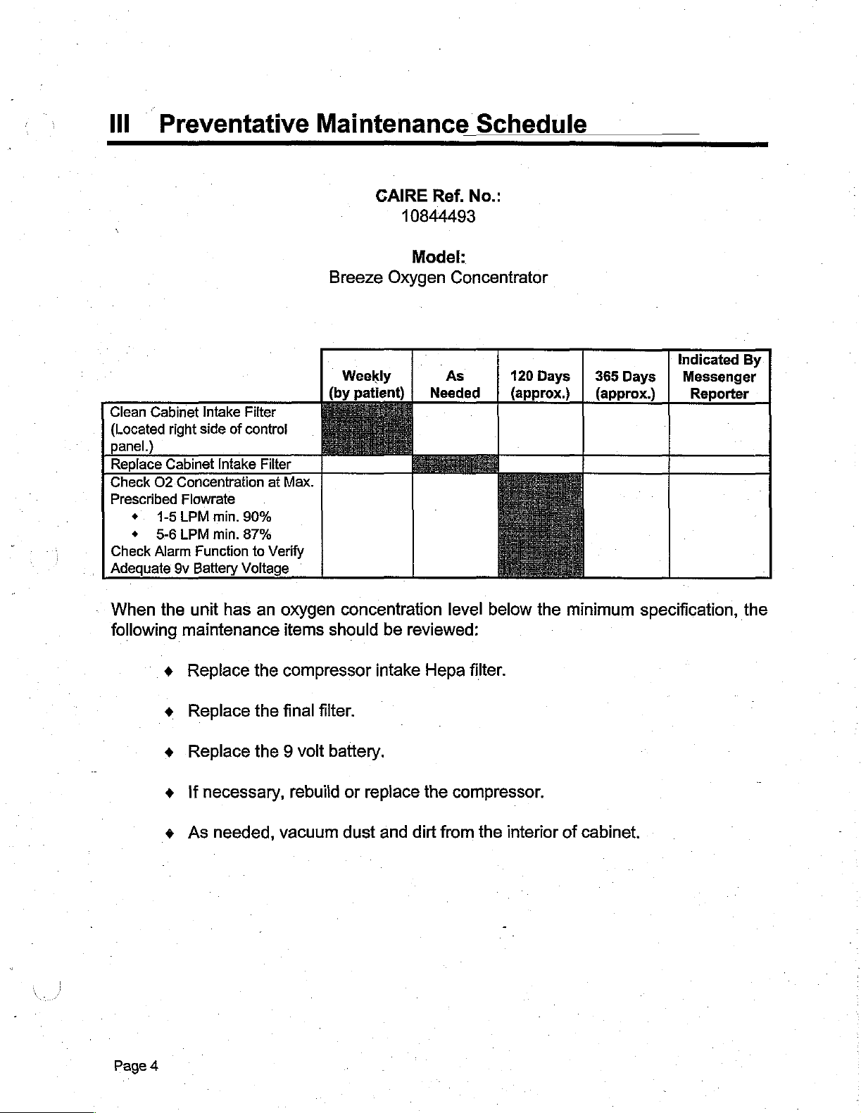
Preventative
Maintenance
Schedule
Clean
(Located
panel.)
Replace
Check
Prescribed
+.
+
Check
Adequate
Cabinet
O2
1-5
5-6
Alarm
Intake
right
side
Cabinet
Concentration
Flowrate
LPM
LPM
Function
9v
Battery
of
Intake
min.
min.
Filter
control
Filter
at
90%
87%
to
Verify
Voltage
Max.
GAIRE
Breeze
Weekly
(by
Oxygen
patient) | Needed
Ref.
10844493
Model:
Concentrator
`
As
No.:
120
Days | 365
(approx.) | (approx.)
Days
Indicated
Messenger
Reporter
By
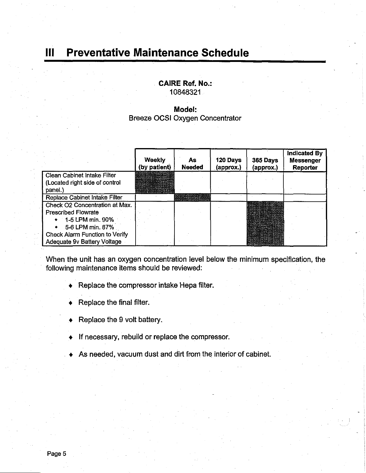
When
following
the
maintenance
+
+
+
+
+
unit
has
Replace
Replace
Replace
If
necessary,
As
needed,
an
oxygen
items
the
compressor
the
final
filter.
the 9 volt
rebulid
vacuum
concentration
should
battery.
or
replace
dust
be
reviewed:
intake
and
dirt
Hepa
the
level
below
filter.
compressor.
from
the
interior
the
of
minimum
cabinet.
specification,
the
Page
4
III
Preventative
Mai
ntenance
Schedule
——
=_=
Clean
Cabinet
(Located
panel.)
Replace
Check
Prescribed
Check
Adequate
+
+
O2
1-5
5-6
Alarm
Intake
right
side
of
Cabinet
9v
Intake
Concentration
Flowrate
LPM
min.
LPM
min.
Function
Battery
Voltage
Filter
control
Filter
at
Max.
90%
87%
.
to
Verify
Breeze
Weekly
(by
patient)
CAIRE
10848321
Model:
OCSI
Oxygen
Ref. No.:
Concentrator
As
Needed | (approx.) | (approx.)
120
Days | 365
Days
Indicated
Messenger
Reporter
By
When
following
the
maintenance
+
+ +
+
unit
has
Replace
Replace
Replace
If
necessary,
As
the
the
needed,
an
oxygen
items
compressor
final
filter.
the 9 volt
rebuild
vacuum
concentration
should
battery.
intake
or
replace
dust
be
reviewed:
the
and
dirt
level
below
Hepa
filter.
compressor.
from
the
the
interior
of
minimum
cabinet.
specification,
the
Page
5
ll!
Preventative
Maintenance
Schedule
Clean
Cabinet
(Located
panel.)
Replace
Check
Prescribed
Check
Adequate
O2
+
+
Alarm
Intake
right
side
Cabinet
1-5
5-6
9v
Intake
Concentration
Flowrate
LPM
min.
LPM
min.
Function
Battery
Filter
of
control
Filter
90%
87%
to
Voltage
Breeze
at
Max.
Verify
CAIRE
Messenger
Weekly
(by
patient) | Needed
Ref.
10961833
Model:
Oxygen
As
No.:
Concentrator
120
Days | 365
(approx.) | (approx.)
Days
Indicated
Messenger
Reporter
By
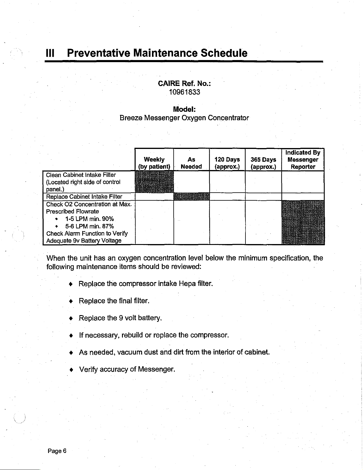
When
following
the
maintenance
+
+
+
+
+
*
unit
has
Replace
Replace
Replace
If
necessary,
As
Verify
the
the
the 9 voit
needed,
accuracy
an
oxygen
items
compressor
final
rebuild
vacuum
of
concentration
should
filter.
battery.
Messenger.
intake
or
replace
dust
be
and
leve!
reviewed:
Hepa
the
dirt
filter.
compressor.
from
the
below
interior
the
of
minimum
cabinet.
specification,
the
,
Page
6
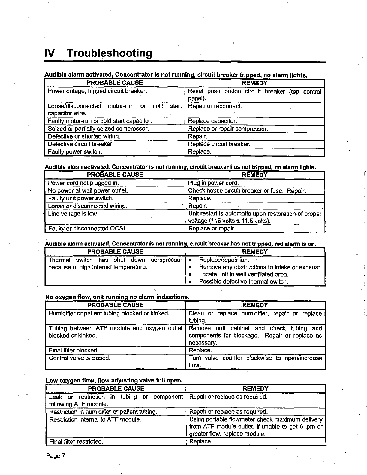
IV
Troubleshooting
--
—
—
Audible
Power
Loose/disconnected
capacitor
Faulty
Seized
Defective
_Defective
Faulty
Audible
Power
No
Faulty
Loose
Line
Faulty
*
Audible
Thermal
because
alarm
outage,
wire.
motor-run
or
partially
or
circuit
power
alarm
cord
power
at
unit
or
disconnected
voltage
or
disconnected
alarm
of
not
power
switch
high
activated,
PROBABLE
tripped
or
cold
seized
shorted
switch.
activated,
wall
is
activated,
wiring.
breaker.
PROBABLE
plugged
power
switch.
low.
PROBABLE
has
internal
Concentrator
CAUSE
circuit
breaker.
motor-run
start
capacitor.
compressor.
Concentrator
CAUSE
in.
outlet.
wiring.
OCSI.
Concentrator
CAUSE
shut
down
temperature.
is
or
cold
is
not
is
not
compressor
not
running,
start
runnin
running,
circuit
Reset
panel).
Repair
Replace
Replace
Repair.
Replace
Replace.
,
Plug
Check
Replace.
Repair.
Unit
voltage (115
Replace
push
or
reconnect.
capacitor.
or
circuit
circuit
circuit
breaker
in
power.cord.
house
restart
or
breaker
Replace/repair
Remove
Locate
Possible
breaker
repair
is
repair.
unit
tripped,
button
compressor.
breaker.
has
circuit
automatic
volts + 11.5
has
fan.
any
obstructions
in
well
defective
no
REMEDY
circuit
not
tripped,
REMEDY
breaker
not
REMEDY
or
upon
volts).
tripped,
ventilated
thermal
alarm
breaker
fuse.
restoration
to
switch.
(top
no
alarm
Repair.
red
alarm
intake
area.
lights.
control
lights.
of
proper
.
is
on.
or
exhaust.
No
oxygen
Humidifier
Tubing
blocked
Finai
Control
Low
Leak
following
Restriction
Restriction
Final
Page
between
or
filter
valve
oxygen
or
ATF
filter
7
flow,
unit
PROBABLE
or
patient
kinked.
blocked.
flow,
restriction
in
internal
restricted.
tubing
ATF
is
closed.
flow
PROBABLE
module.
humidifier
to
running
CAUSE
blocked
module
adjusting
CAUSE
in
tubing
or
patient
ATF
module.
no
alarm
or
and
oxygen
valve
or
tubing.
indications.
kinked.
outlet
full
open.
component
REMEDY
Clean
tubing.
Remove
components
necessary.
Replace.
Turn
flow.
.
Repair
Repair
Using
from
greater
Replace.
or
replace
unit
valve
or
replace
or
replace
portable
ATF
module
flow,
cabinet
for
blockage.
counter
as
as
flowmeter
outlet,
replace
humidifier,
and
Repair
clockwise
REMEDY
required.
required.
check
if
unable
module.
repair
check
tubing
or
to
open/increase
-
maximum
to
get 6 Ipm
or
replace
replace
delivery
and
as
or
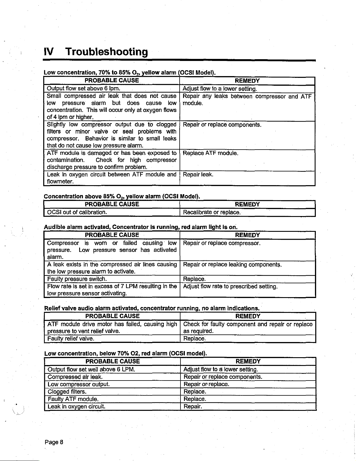
IV.
Low
Output
Small
low
concentration.
of 4 Ipm
Slightly
filters
compressor.
that
ATF
contamination.
discharge
Leak
flowmeter.
Troubleshooting
concentration,
flow
compressed
pressure
or
higher.
low
or
minor
do
not
cause
module
pressure
in
oxygen
70%
PROBABLE
set
above 6 ipm.
air
alarm
This
will
compressor
valve
Behavior
low
is
damaged
Check
to
circuit
to.85%
CAUSE
leak
that
but
occur
output
or
is
similar
pressure
or
has
for
confirm
between
O,,
does
does
only
at
due
seal
problems
to
alarm.
been
high
problem.
ATF
yellow
oxygen
alarm
not
cause
cause
flows
to
clogged
small
leaks
exposed
compressor
module
low
with
to
and
OCSI
Model).
Adjust
flow
Repair
module.
Repair
Replace ATF
Repair
any
or
leak.
to a lower
leaks
replace
module.
REMEDY
setting.
between.
components.
compressor
and
ATF
Concentration
OCSI
Audible
Relief
Low
out
alarm
Compressor
pressure.
alarm.
A
leak
exists
the
low
Faulty
pressure
Flow
rate
low
pressure
valve
ATF
modute
pressure
Fauity
Output
Compressed
Clogged
relief
concentration,
flow
Low
compressor
Faulty
ATF
Leak
in
above
PROBABLE
of
calibration.
activated,
PROBABLE
is
Low
in
pressure
is
set
in
sensor
audio
PROBABLE
drive
to
vent
valve.
PROBABLE
set
well
air
filters.
module.
oxygen
circuit.
85%
worn
pressure
the
compressed
alarm
to
switch.
excess
activating.
alarm
motor
relief
valve.
below
above 6 LPM.
leak.
output.
O,,
CAUSE
Concentrator
CAUSE
or
sensor
activate.
of 7 LPM
activated,
CAUSE
has
70%
CAUSE
yellow alarm
failed
causing
has
air
lines
resulting
concentrator
failed,
O2,
causing
red
(OCSI
is
running,
low | Repair
activated
causing
in
the
high
alarm
(OCSI
Model).
REMEDY
Recalibrate
red
alarm
Repair
Replace.
Adjust
running,
Check
as
required.
Replace.
model).
Adjust
Repair
Repair
Replace.
Replace.
Repair.
light
or
replace
or
replace
flow
rate
no
alarm
for
faulty
flow
to a lower
or
replace
or
replace.
or
replace.
is
compressor.
to
indications.
component
on.
REMEDY
leaking
prescribed
components.
components.
REMEDY
REMEDY
setting.
setting,
and
repair
or
replace
Page
8

V
Electrical
System
Components
POWERSWITCH
The
power
mounted.
+
Pole 4 is
push
high.
+
Pole 3 is
©
4
Pole 2 does
+.
Pole 1 is
Note:
When
pressure
with
the
powers
open
will
the
the
light
switch
For
the
used
button
used
not
the
switch
unit
contacts
plugged
alarms.
pressure
when
the
(Reference
is a three-pole,
Breeze
to
is
low,
to
not
exist
used
power
in
When
switch
unit
448)
concentrator
switch
(green
switch
on
for
the
switch
are
closed
or
not
powered
contacts,
is
“ON”
single
AC
power
lamp
the
alarm
this
switch!
Breeze
is
“ON”,
(low
plugged
on,
and
and
correctly
throw,
two
on
lighted);
circuit
concentrator.
the
sets
and
audio
push
of
and
(9
pressure).
in. A 9
the
VDC
compressor
deactivate
powered.
poles
off.
off
volt
alarm
This
the
button
are
The
AC
when
DC)
will
audio
battery
will
audio
type.
in
on
sound
It
service.
power
the
push
and
off.
when
alarm
{reference
quickly
alarm.
The
is
panel
is
on
button
will
#19)
build
green
when
the
the
is
sound
pressure,
lamp
COOLING
The
cooling
the
right
side
the
intake
then
is
blown
across
left
Caution:
airflow
Caution:
to
HOUR
The
indicates
running
hours.
time
the
rear
for
assure
METER
hour
The
again.
of
proper
meter
the
time
FAN
filter,
The
(Reference
fan
provides
of
the
the
into
compressor
the
cabinet.
patient
cooling.
The
cooling
cooling
(Reference
is
located
total
to
1/10
display
#27)
cool
air
through
upper
cooling
the
elapsed
will
front
compressor compartment.
after
must
air
intake
of
air
is
cooler
clean
and
the
oxygen
panel
drawn
tubing,
the
exhaust
of
intake
#18).
behind
hour,
then
running
and
the
reads
return
front
time
to a maximum
to
000000.0
the
inlet
air
the
concentrator.
through
and
concentrator.
the
The
finally
air
filter
grilles
must
-
for
panel
the
access
concentrator.
hours
filter
(reference
ATF
module
cooling
exits
weekly
remain
door.
running
and
begin
After
air
at
the
to
maintain
The
The
time
#1)
passing
compartment
is
then
directed
grille
at
the
free
of
obstructions
hour
meter
display
of
99,999.9
to
accumulate
located
through
and
the
upper
required
resolves
the
at
-
Page
9

V
Electrical
System
Components
CIRCUIT
The
pole
button
the
BREAKER
AC
electrical
circuit
is
located
depressed
PRESSURE
The
pressure
function
has a 9
plugged
switch
assistance.
ATF DRIVE
The
valve
ATF
that
when
volt
into
may
drive
system
breaker.
at
position
SWITCH
switch
the
battery
an
AC
need
MOTOR
cycles
to
motor
the
(Reference
is
The
circuit
the top
for
the
(Reference
is a sensor
oxygen
power
product
supply
service
be
adjusted
(Reference
is
simply a very
sieve
#5)
protected
breaker
right
of
the
Breeze
#52)
that
pressure
and
outlet.
beds
For
to a slightly
bottom
of
the
from
overloads
is a push
contro!
unit
will
close a circuit
will
panel.
to
operate.
falls
activate
applications
lower
.
of # 40)
accurate
ATF
clock
module.
and
button
The
below
even
at
higher
set
point.
drive
short
reset
activating
normal.
when
type
push
circuits
button
the
This
the
altitudes
Call
CAIREº
motor
that
by a single
and
the
must
alarm
alarm
unit
is
the
rotates
push
be
in
circuit
not
pressure
for
a
CAPACITOR
The
air
compressor
COLD
The
of
air
torque
AUDIO
A
device
monitoring
START
cold
the
compressor.
compressor
will
ALARM
DC
voltage
on
start
allow
board
system.
MOTOR
motor
CAPACITOR
capacitor
This
motor
(Base
audio
the
the
during
unit
device
OCS!
RUN
models
(Reference
requires a running
KIT
(optional)
kit
is a device
device
to
circuit
provides a momentary
start
up
start
at
only).
for
the
alarm
board
#30)
capacitor
(Reference
that
installs
to
provide
lower
(Reference
temperatures.
function.
for
the
parallel
additional
#59)
This
units
equipped
for
proper
#43)
into
additional
torque.
function
operation.
the
capacitor
capacitance
This
is
provided
with
the
circuit
to
additional
for
by
oxygen
the
~
a
Page
10

V
Electrical
System
Components
πας
TEMPERATURE
A
temperature
cabinet
event
AIR
A
twin
motor
RED
A
this
are
GREEN
A
When
provided
temperature.
of
cabinet
COMPRESSOR
cylinder
is
provided,
LIGHT
red
LED
light.
provided
LIGHT
neon
AC
units
by a circuit
SWITCH
switch
ventilating
air
compressor
supplying
(only
is
When
green
for
provided
units
by a circuit
(only
are
for
lamp
equipped
(Thermal
is
provided
This
protection
fan
(Reference
compressed
Base
to
indicate
are
board
Base
is
board
Models)
equipped
mounted
Models)
provided
with
the
mounted
Switch)
to
shut
off
is
provided
failure
or a blocked
#20)
with
an
integral
air
(Reference # 50)
an
alarm
with
the
red
(Reference
to
indicate
OCS!
option
green
(Reference
the
air
compressor
mainly
ventilating
split
for
the
oxygen
condition.
OCSI
indicating
indicating
option
#49)
that the
the
green
#32)
to
phase,
The
9-volt
lamp.
unit
lamp
lamp.
in
the
protect
capacitor
concentration
the
is
the
air
intake/exhaust.
DC
battery
red
lamp
properly
functions
event
unit
in
run,
electric
process.
powers
functions
powered.
are
of
the
high
OCS]
The
sensing
Included
functions
light).
70%
70%
the
MESSENGER
The
system
CIRCUIT
OCSI
technique
on
If
the
and
the
red
BOARD
system
this
(red
light),
oxygen
85%
lamp
the
OCSI.
CONTROL
Messenger
provides a means
is
circuit
Control
telephone/computer
(optional)
an
on
board
to
determine
board
low
oxygen
concentration
yellow
will
lamp
light.
BOARD
Board
of
interface.
(Reference
oxygen
the
oxygen
are
the
indicating
concentration
is
85%
is
lit,
and
See
section
」
(optional)
interfaces
remotely
This
circuit
#51)
sensing
concentration
lights
(yellow
or
higher
if
the
oxygen
VIII
Service
(not
shown)
with
the
monitoring
board
system
OCSI
the
carries
that
in
the
for:
low
light},
the
green
concentration
Instructions,
*
board.
Breeze operation
various
utilizes
battery
and
lamp
The
an
product
power
is lit,
for
Messenger
power
ultrasonic
stream.
and
alarm
on
(green
if
between
falls
below
calibration
via
a
and
signals.
~
of
Page
11

VI
Compressor
Replacement
8a.
COMPRESSOR
Make
Use a Phillips
Use a Phillips
Pull
Use a 9/32”
Slide
Use a 1/8”
bolts.
Slide
Disconnect
gently
sure
unit
screwdriver
screwdriver
compressor
socket
hose
off
barbed
hex
compressor
compressor
pull
out.
is
turned
cover
to
(Allen)
assembly
off
and
to
to
off.
loosen
elbow.
wrench
out
harness
KIT
unplugged.
remove
remove
the
hose
to
remove
of
unit,
by
depressing
INSTRUCTIONS
the
bolt
for
the
the
bolt
for
the
clamp.
by
for the
front
compressor
pulling
in a horizontal
the
filter
access
compressor
compressor
side
of
the
door.
cover.
discharge
mounting
direction.
plug
and
line.
shoulder
then.
8b.
10.
Page
Disconnect
do
not
have
Reverse
compressor
are
inserted
Plug-in
compressor
12
spaded
Molex
steps
assembly
into
unit
and
assembly
#8
the
thru
run
terminal
quick
disconnect
#1
to
is
positioned
spring
to
verify
is
not
connections
harness.
install
ends
mounted
new
on
and
the
performance.
in
(4)
on
older
compressor
springs,
mounting
an
such
If
unit
optimum
style
Breeze
assembly.
that
bolts
are
is
excessively
manner.
units,
Note,
the
rubber
centered.
which
make
noisy,
sure
grommets
the
_

VII
ATF
Module
Replacement
Make
Use a Phillips
Puil
Use a Phillips
Use a 9/32”
the
Pull
Remove
Remove
installed
sure
rear
ATF
off
unit
screwdriver
cover
screwdriver
socket
module.
oxygen
ATF
wires
ATF
module
orientation
ATF
is
turned
off.
to
Slide
output
from
MODULE
off
and
to
remove
to
remove
remove
hose
off
line
at
top
wire
from
of
the
unit
ATF
KIT
unplugged.
the
the
the
hose
stub.
of
the
clip
near
by
lifting
module
INSTRUCTIONS
bolts
(4
typ.)
for
ATF
clamp
ATF
base
straight
with
clamp
for
module.
of
the
the
the
clips
air
module.
up
unit.
the
(3
typ.).
intake
and
then
rear
line
cover.
at
the
out.
Note
base
'
of
the
98.
90.
10.
11.
Unplug
out.
Disconnect
connect
Reverse
module
that
module,
wires
Plug
ATF
directly
steps
has a bracket
clips
be
into
in
unit
wire
harness
spaded
into a support
alert
clip.
and
terminal
to
terminal
#9
thru
to
run
to
#1
on
the
wire
verify
by
depressing
connections
block.
to
install
underside
on
the
main
position,
performance.
the
(2)
new
of
unit.
so
side
on
older
ATF
the top
Also,
they
do
of
the
style
sieve
dome
when
not get
plug
and
then
-
Breeze
module.
(90°
pinched. Reinsert
units,
Note,
from
oxygen
installing
gently
which
the
outlet)
the
pull
ATF
ATF
Page
13

Vill
Service
Instructions
—
--
O
ZIA
nus
Tools
Phillips
Socket
Flat
pwm
Applicable
1,
Procedure
11.
Calibrated
Breeze
.
Verify
Using
Using
ENA
take
은
Locate
οι
*
Carefully,
set
Allow
Connect a calibrated
Verify
Using
oENEe
pins,
Reconnect
pinched.
Reconnect
Screwdriver
Wrench
Blade
off
between
Screwdriver
Oxygen
Models
OCSI
the
Concentrator
the
Phillips
either
the
top
control
the
combination
plug-in
3-4
unit
to
warm-up
the
outlet
the
tip
by
touching
top
rear
#2
7mm
of
the
control
(or)
Concentration
screwdriver,
socket
panel.
unit
LPM.
oxygen
oxygen
flat
both
cover.
OCSI
Torx™
with
CALIBRATION
Screwdriver
Electrically
Meter
is
tumed
off
remove
wrench
or
the
LED/OCSI
and
turn
Concentrator
for a minimum
concentration meter
concentration
blade
posts
panel,
screwdriver,
simultaneously
paying
#120
Insulated
and
unplugged.
screws
Torx™
(4)
screwdriver,
board.
on.
of 5 minutes.
is
above
94.5%
carefully
for
30
close attention
Handle
to
take
Note,
the
-
to
the
ground
seconds
that
off
rear
remove
outlet
outlet.
out the
(see
no
wires
cover.
screws
flow
(2)
should
calibration
page
#17).
or
tubes
are
to
be
Page
14

ysl]
sed
aeds
XI
1
ebed

9IQISIA
“eIgISIA
"9IQISIA
JON
'elqlsAloN
[69
]
JON
JON
“elqlslA
JON
al
ebed

suld
:I9po
UONEIGIES
ISDO
1917
51100
eds
XI
、
`
ерой
эзея
1
ebed

IX__Spare
Ref.
No.
4
2
3
4
5
6
7
8
9
10
11
12
13
14
15
16
17
18
19
20
21
22
23
24
25
26
27
28
Part
Number
10844493
10848321
10740408
10740444
10786490
14165
10848582
10740424
10844549
10848339
10844670
10861058
10739933
10740446
10801389
10855871
10739992
14709
10740420
10786481
CA110060
10855900
10877375
10850421
10879320
10893666
888-006-103
10844506
13320
15058
Parts
List
Breeze
Breeze
Cabinet
Cabinet
O2
02
Circuit
Power
LED
LED
Control
Flow
Control
Access
Cover
Compressor
Caster
Patient
Silicone
Hour
Battery 9 Volt
Compressor
Relief
HEPA
Black
Silicone
Hose
Heat
Cooling
Fan
OCSÍ
Filter
Filter
Outlet
Fitting
Outiet
Nut
Breaker
Switch
Control
Control
Panel
Meter
Vaive
Panel
Bolts
Bacteria
Tubing
Meter
Valve
Intake
Muffler
Tubing
Clamp
Exchanger
Fan
Mount
Insert
——
Frame
(panel
(panel
(8
amp)
Button
Panel
Panel
{no
plumbing
0-6
LPM
Knob
Door:
Cover
Filter
3/16"
Assembly
30
PSI
Filter
3/8"
Description
mount)
mount)
Label
(base
Label
(OCSI
included)
(includes
ID
Clear
ID
Blue
model)
model)
foam)
a
-
Spares
Per
100
Units
3
3
1 1
1
1
1 1
1 1
1 1
1 1
1 1
1
1 1
6 6
1
1
3
1
1
1 1
1 1
1 1
3
1 1
1
1
1 1
1 4
4
Quantity
Used
AIR
AJR
1
1
1
1
1
1
4
1
5
ft.
1
1
13
in.
4
4
Quantity
Ordered

IX
Spare
Ref.
No.
29
30
31
-
32
33
34
35
36
37
38
39
39
40
41
42
43
44
45
46
47
48
49
50
51
52
53
54
55
56
57
57
Part
Number
14156
10829453
10780881
10785518
10875951
10800546
10747773
10784451
10747829
10747845
10855889
10914754
10822631
10844602
10844531
10871686
10786609
10740432
701-007-401
.
10739925
10740264
10914762
10846616
10879311
10880013
10786570
CA403730
10847424
10915870
10740430
10888496
Parts
ㆍ
List
Mounting
Fan
Capacitor
Capacitor
Thermal
Compressor
Compressor
Compressor
Compressor
Compressor
Compressor
Power
Power
ATF
Terminal
Fan
Cold
ATF
ATF
Check
Control
Power
Green
Red
OCSI
Pressure
Wire
Cable
Heat
Base
Strain Relief
Strain
15
Bracket
Switch
Cord
Cord
Module
Block
Cord
Start
Capacitor
Mounting
Mount
Light
Clip
Valve
Valve
On/Off
Light
Harness
Harness
Board
Switch
Clip
Tie
Exchanger
Model
Control
Relief (0.30"
Bolt
UF
(150F)
Mount
Mount
Mount
Mount
Mount
Mounting
(0.25"
(0.30"
Kit
(only
(0.25"
Spring
Footpad
Shoulder
Shoulder
Grommet
OD)
OD)
Bolt
Switch
(base
unit
Mounting
Panel
OD
OD
Description
Bracket
(base
model
model
SN
4419704060
Foam
w/Lights
Cord)
Cord)
Bolt
Washer
only)
only)
ous
`
and
newer)
men
|
Spares
100
Per
Units
1
1 1
1
1
1
1
1
1
1
1
1 1
1
1 1
1 1
1
1 1
4
1
1 1
1 1
1 1
1 1
1 1
1
1 1
1
2
1
1 1
1
1 1
Quantity
Used
4
1
1
4
4
4
4
4
2
4
1
3
3
1
1
2
4in.
1
παρω
Quantity
Ordered
NÍ
Page
1

IX
Ref.
No.
58
59
*
*
*
*
*
*
*
*
+
*
Not
shown
Spare
Part
10785500
10750913
10860987
10844573
10740433
10844557
10848347
10860848
10855491
10914594
in
Parts
Number
11420
diagram.
List.
Silicone
Audio Alarm
Instruction
Packaging
Patient
Rear
Serial
Serial
Control
External
Internal
Tubing
Label
Kit
Operating
Cover
No.
Label
No.
Label
Panel
Messenger
Messenger
72"
(base
model
Instruction
(base
(OCSI
Mounting
ID
Green
model}
model)
Screws
Description
only}
i
Booklet
Spares
100
i
Per
Units
1
1
1 1
1 1
1
1 1
1 4
4 1
2 2
N/A
N/A
Quantity
Used
7.5
in.
1
1
N/A
N/A
Quantity
Ordered
Page
20

IX
Ordering
The
Spare
Information
following
replacement
1.
Compile
ordered.
2.
Fill
out a purchase
a.
Purchase
b.
Name
c.
Name
d.
Quantity,
ordered.
steps
parts
a
list
order
and
and
part
Parts
should
for
an
existing
of
all
order
number,
address
address
number,
List
be
used
unit:
equipment
containing
of
billing
of
shipping
description,
when
and
the
location.
location.
and
ordering
replacement
following
unit
cost
new
equipment
parts
information:
for
each
item
to
or
be
nm
|
3.
Telephone
begin
Toll
Toll
Phone:
Fax:
4.
Mail
to:
CAIRE,
3505
Burnsville,
All
new
collect,
UPS
“prepaid”,
added
invoice
particular
order.
immediate
Free
Phone
Free
Fax
the
completed
Inc.
County
MN
equipment
via
your
to
the
final
date.
All
carrier
or
fax
processing
(U.S.A.):
(U.S.A.):
Road
42
55306-3803
will
specified
and
the
invoice.
shipments
or
method
CAIRE
purchase
West
be
shipped
carrier.
shipping
Payment
will
of
shipment
us
at
one
of
the
of
the
order:
1-800-48
1-888-WE
CAIRE
CAIRE
1-952-882-5179
1-952-882-5178
order
for
U.S.A.
either
“prepaid”,
All
replacement
charges
originate
for
equipment
for
replacement
from
is
desired,
numbers
listed
(1-800-482-2473)
(1-888-932-2473)
confirmation
F.O.B.
parts
will
and
parts
Burnsville,
Minnesota.
specify
below
of
the
order
Burnsville,
be
sent
by
parts
will
be
is
CAIRE
If
when
placing
to
or
a
-
Page?
`

Азивием
19/89(
Juouojeys
pal
-
[S90
ААцемем
929919
рие
э2эела
X
SIeuelew
sq
SASIS
IIBUS
』BInOSIOUU
(。SJUSUOdUIOO。)
미
sloajep
JTV
шоц
[18
SIUBJBA
зизиодшоо
894)
θα
[85
допроле,
è
Yes)
Jonpoid
szss1g
pue
suo
PIND
MaU
YIee
yeu}
(Jeseyoind,)
Jeseyond
jeulGuo
aly
о;
зиенем
(319)
"941
ЧО
Apleq
peplAcJd
ヨ
HIVO
юззел9шоо
‘Mojeg
se
1]deoxa
papiaoid
[je
μθυιάμης
SQUELIEM
se
ideoxe
JO
эымуо
eyep
чиешанце
oy}
“Mo¡eq
Woy
pepjacid
Jo
злеэд
9160
(1)
941
se
иелэз
июд
jdeoxe
1о
81694
ромед
Чиэша
(ϱ)
е
еэл
це
20;
jo
Ччецешулом
до
아티
ромед
641
е
шоц
10}
рие
Чузиешулом
siesÁ
|епауеш
(g)
SAY
и!
зреэр
рие
JO
poled
зенеуеш
шодээд
e
Joy
и
Чщзчецьиом
sjoajep
эа
пецз
шо
selnpou
9914
рие
yonpoig
Joj
HIM
"人
JuJBA
aiqlsuodsel
Bevo
Чопз
PD1IUUH
эло}э4
руе
Алэлнер
10
зКер
(0)
че}
чцим
jonpos]
uses
«Queue
aq
SIHH
1OU
DIOA
用
реуши
A
ヨ
IIBMS
HIVO
$14}
OS
Aq
"08J9D
OD
peueAco
oj
eunllej
DejJOdJhd
]ou
eus
asneo
6
pue
yo
Аюлоозр
2
suononysu!
LOJ
UESUE
JO
зАер
Joadsui
Dugessdo
BABU
08
ol
Aljny
ицим
seuluuuelap
s,
EYS
JHIVO
Видим
J9SEy9iNg
UNM
Ivo
и!
эреш
eoueploooe
“84190949
“uogoedsul
эа
19044
녀
910990
AJUBLIEM
1900010
s,JYJVO
EYS
041
Jo
30
doeelq
Aueuem
упзги
ejesedo
е
ло}
зе
0]
palull
шею
'цоцм
sesibe
Аие
sidl
Ашенем
Osje
зец;
elojeq
Joseyong
зэеибе
jEu
jo
doeeiq
seeJ46e
лэцип}
“esn
pef6elle
JosEuoJnd
лозецоапа
oy
ind
Aue
sj
40
suosied
syo0ae
Aq
ey,
epeu:
Áq
pesnes
sedes
sjoejeg
Jo
чиерюов
(
q)
‘ээпде
:ayliwo
'эзпзши
Aq
poAoJdde
Ла
раузуззэози
osoul
ueu
“Joseyoud
зиэшеов[4е:
Joeuio
ionpould
¡eur6Lo
“JYIVO
Jo
SU)
Jredey
ey
0)
peuinja:
UBUM
Apeai
juaned
ag
0)
JUN
ey)
J9A09
JIM
UOIUM
say
jeujulou
e
ebleyo
UJIM
JO
SUSUOdLUOJ
(
JOMUOI
9
)
sua]!
SY]
UIUJIM
SOJASS
Jo
OSN
JOU
Sugnos
(A
SSSNEI
)
AWO
¡eunon
ISUJO
Ag
JO
(
pozuoujne
y
“POD
)
201
JO
Ájdde
SJOY
jou
1Ou
suosied
(3)
seop
UBa]
人
JO
JuBJJBA
Jl
pue
yO
Jesm
PB1IUUII
Uey)
IEUJJOU
Joyjo
SIUL
Ayedold
peaunleJ
'SA0E
P9]e]s
slueuoduoo
‘predesd
SSOIPpe
jy5jey
pue
ey)
sjueuodulog
sionpoud
je
Зо
SUNİ
12е}409
pue
sjonpoig
fq
рпоцз
panssi
эзецота
Ulmes
JagLunnN
yeys
‘элоде
uoliezuouinY
Jeseyolmg
рее1з
Аменем
ранил
941
417
Ájdusoo
]0u
seop
juauodulo)
JO
JONPOIH
E
JEY)
SOADISO
эзецолпа
И
"эзиэахе
“Jyuivo
leheleN
злэзецола
Áq
unjsd
pajoamp
e
зе
Aq
решите.
y
payuep;
“eseyomd
рие резпуел
Áedo:d
jo
ejep
pue
э4
ey,
Jim
Jeumjuos
jo
JegtunN
10014
Buidd¡ys
uogezuoyny
Buipincid
peroldde
pue
[EUSIEN
wejqoid
3yivo
UNS}
aux
e
ul
Buiguosep
pebexoed
E
JNOUJIM
Je
YAHLYNA
UOREINP
38192
OL
60110
CALINIT
30
BU}
05640470
ON
350
10}
LON
ヨ
CIUSUBLUMIOM
AHL
AVH
ey,
LAG
jo
punyes
JO
1U9UOdUJOO
JO
jonpold
seAgoejep
sl
Jo
Jueusoelda
Jo
Jlede
0}
pey
se
AJuBJJBA
人
DIUJI|
SIU1
JO
HOBS』d
Aue
Joj
slqelleAe
selpauusJ
DYL
OL
TIVHS
CILVIIY
ONIGNTIONI
[046
ヨ
HIVO
[BUS1BLUI
YO
“JaBuoj
"LON
JO
UI
S109J9D
LNO
O
sI
зелецоцм
ONISIYY
ヨ
1
UIOJJ
ヨ
V
ヨ
99JJ
ヨ
S
‘лэзецозла
‘STOVIAVO
ヨ
8
HO
IIBUS
ヨ
SHUgUOduuo
H1
0]
FALLINNA
justudiys-es
HA
ヨ
‘AUNLYVN
つ
pue
YO
jo
S}OnPOJ』
AUVIANIXI
ejep
MO
eyy
CONDI
DSJIBd9J
uloy
“TVIOAAS
ANV
sÁep
о
JO
1U9ul92BIdeJ
(06)
5234
‘IVUANIO
Аеши
HO
ло
1BU)
Амешем
1509
"TVILN
SIUEJBA
ヨ
‘8285071
TIO
[ебро
HIVO
ヨ
SNOO
эц}
'SIOVWYG
ヨ
до
QNV
IVO
uonrod
JO
S33J
UONGIOSIP
pauldxeun
404
SA3NNOLLV
ALINISVIT
elos
au}
ad}
Jo
1ON
AUIVO
Ins
40
LNIWILVIS
эмаптом
‘азпайи
HO
NOLLVINISIUdIS
HO
“CISSINAXI
"S334
YO
1809
'S38807
'SI9VAWO
HINS
40
ALNAISSOd
ZHL
JO
GISIAQV
NI3A
SVH
ヨ
HIVO
JI
NIAI
‘LNANdINOI
ON
'SNOLLVINISINdIU
‘3SOdUNd
UVYINILLYVA
HO
VUOI
SILUNVESNVA
SSANLId
ON
ONY
JOVI
ALITISYLNVHOYAN
SVH
"ALNVURIVAA
3YIVO
‘ALNVUNVM
GELINIT
40
S3LLNVYUVM
SIHL
GILINI
YIL'IV
G3TIdNI
SIHL
YO
FONVHD
YO
OL
1d39X3
GALANT
AVA
Su)
seal
Aueuem
pay
slut
"EJOSOUUJ
“Ájdde
доц
Леш
Ul
ипоо
зиоцени
|елоре}
элоде
JO
SJE]S
эц}
©
оз
UJ
IUPNOJG
‘зебешер
`8}2}$
eq
jsniu
pue
mej
еюзеции\
0}
э}е}5
|едиепЬэзиоо
шоц
ÁJeA
JO
yojya
|Ejuapiau
sjy6u
Аа
ио
решелов
Jeyjo
ло
зедивлем
saey
эа
IIBUS
Ауиелем
os¡e
Аеш
репёш!
лезецолта
ио
зиодении
раиши
“siybu
9141
моде
JO
цовела
10;
зицер
Аиу
¡ebay
зои
oyjoads
ор
søjejs
Jeseyolnd
euuoS
zz
ebeg

XI
Return
Policy
때때
vat
prata
==
When a Breeze
should
If a problem
encountered,
be
inspected
with
reference
Troubleshooting
lf
these
procedures
the
problem,
the
taken:
1.
Call
CAIRE,
numbers,
Service
with
problem
“Return
assigned
Purchase
and
Representative.
the
unit.
cannot
Authorization
to
Order
referenced,
Technical
Service
time.
2.
Carefully
the
container,
3.
Write
the
Note:
4..
Return
carrier
Otherwise
package
unit
in
its
precisely
the
Return Authorization
top
of
the
the
unit
to:
Concentrator
is
immediately.
the
unit
should
should
Chart
in
Section
do
not
provide a solution
following
using
one
steps
of
the
request a Medical
State
If
it
is
determined
be
solved
by
Number"
the
unit
or
part(s).
Number
please
give
is
this
Representative
the
parts,
original
shipping
unit
or
shipping
as
container.
will
be
parts
by
shipped.
returned.
received,
it
be
be
made
to
the
IV,
page
7-8.
should
be
toll-free
Technical
the
problem
that
the
the
TSR,
a
will
be
Ifa
to
be
number
to
at
or
repack
Number
the
that
on
professional
for
Restocking
If
it
becomes
CAIRE
use
the
1.
Notify
CAIRE
When
personnel,
Policy
after
the
following
the
using
contacting
following
a.
State
equipment
b.
Give
be
returned.
c.
State
2. A Return
issued
CAIRE
When
factory,
must
Note:
3.
All
to:
CAIRE,
3505
Burnsville,
in
for
the
the
appear
Otherwise
equipment
Inc.
County
MN
necessary
shipment
“Restock
Customer
one
to
has
Service
of
the
cancel
Policy”
customer
it
will
be
necessary
information:
the
the
the
Serial
quantity
to
equipment
and
be
returned.
Number
Authorization
the
name
of
the
the
equipment
equipment
Return
on
box
must
Road
is
Authorization
the
packing
will
be
be
returned
42
West
55306-3803
an
been
received,
procedure:
Department
toll-free
numbers.
service
to
description
of
each
purchase
Number
will
distributor
to
be
returned.
shipped
to
slip
and
returned.
“prepaid”
-
U.S.A.
order
with
relay
the
of
unit
date.
be
by
the
Number
boxes.
at
to
CAIRE,
3505
Inc.
County
Burnsville,
All
equipment
shipped
When
CAIRE,
the
of
“prepaid:
the
it
distributor
the
“Repair
giving a detailed
performed.
Page
23
Road
MN
55306-3803
returned
defective
will
be
serviced
as
soon
Cost
listing
42
West
to
CAIRE
item(s)
Sheet”
is
and
as
possible. A copy
will
of
any
U.S.A.
must
be
received
returned
be
at
to
enclosed
maintenance
4.
Finally, a “Credit
the
distributor
received,
CAIRE.
Memo”
when
all
inspected,
will
equipment
and
restocked
be
issued
has
by
to
been

(2
30
1)
MVH9VI
Y
XIONIddY
ONTEIA
£8192801
ZH
O9/470A
StI
13000
ISYO
173348
MLN
46
Bi
στη
a
CET]
34055284
IOLUMS
e
660
ls
fala
686
[2
~
y
Επι
lı
EW
NOSSINANOO
davis
ΟΔΟ)
AGLIANA
0109
|:
,
7008
“1104
$11
OL
E
wiht
vor
el
ㆍ
same
amu
EL]
HOLAS
IMANOL
002]
.
0100
Mo
ον

|
i
|
|
|
|
CAPACITOR
TEMPERATURE
Sør Ten
BREEZE
10878183
CAPACITOR,
COLD
ROOT
START
10
113
HOLT,
dO
Ha
COMPRESSOR
2008
BLE.
MIS
ET
HOLT,
60
7
y
R
>
demo
BREEZE
ee
BASE
ORAWING
n
>
AC
POTER
COND
an
3
AL
TERNIRAL
BLOCK
©
ALK
BIEN
O
BACK
RUE
BACK
were
Aq
205
YOLU,
MODULE
MOTOR
DRIVE
Ne
60
HZ,
KA
εκ
kb
.
3
BLACK
A
у
니도
COOLING
RT,
60
FRR
HT
PANEL
LANPS
SON
MESSENGER
OPTION)
.
1
lo
GARA.
E
RÉIS”
so
M
conecta
A
o
rio
por,
Net
cars]
O
1
|
3
d
4
ir,
o
5
-
que
ия
ce
ΑΝ
uno
:
E
E
WITH
WIRING
APPENDIX
OCSI
DIAGRAM
115
A
VOLT/60
(2
OF
2}
HZ

”
ass
-
131100
13940
3
JAWA
wus
BEM
(9418)
-
“o
HANOSNYEL
BIONISS
SNOI1dO
(I
30
839Ν1951Η
NVA9VI
1}
A
XIGNIddY
ONY
AO1
1530
8ΙΥ
58194901
HEIM
373389
YIONVHOXI
IVIR
137100
“Iv
39800
1830
ASSV
805S39MdN0
8
3
10000
30SN3S
1990
JAVA
MOT
IN
339435534
08008
431344013
-
4373408
131NI
841111
{Yd3H}
SAWA
331738
う
|
-
.

 Loading...