

Caiman Lektrafuse Instructions For Use Manual
Aesculap®
Aesculap Endoscopic Technology
Valid for units with software version 2.0 and higher
Instructions for use/Technical description
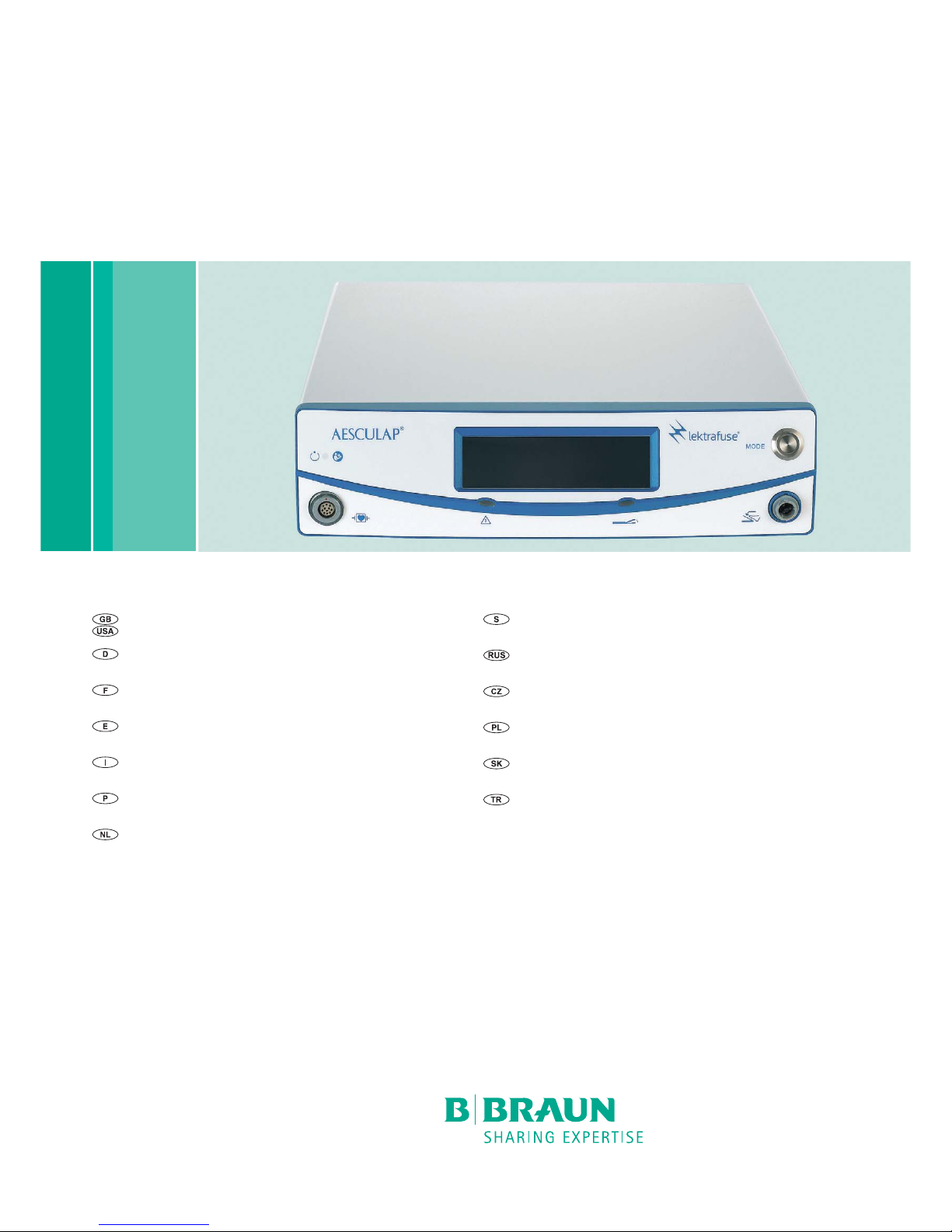
Lektrafuse HF generator GN200
Gebrauchsanweisung/Technische Beschreibung
Lektrafuse HF-Generator GN200
Mode d’emploi/Description technique
Générateur HF Lektrafuse GN200
Instrucciones de manejo/Descripción técnica
Generador AF Lektrafuse GN200
Istruzioni per l’uso/Descrizione tecnica
Generatore HF Lektrafuse GN200
Instruções de utilização/Descrição técnica
Gerador de AF Lektrafuse GN200
Gebruiksaanwijzing/Technische beschrijving
Lektrafuse HF-generator GN200
Bruksanvisning/Teknisk beskrivning
Lektrafuse HF-generator GN200
Инструкция по примению/Техническое описание
ВЧ-генератор Lektrafuse GN200
Návod k použití/Technický popis
VF generátor Lektrafuse GN200
Instrukcja użytkowania/Opis techniczny
Generator HF Lektrafuse GN200
Návod na použivanie/Technický opis
VF generátor Lektrafuse GN200
Kullanım Kılavuzu/Teknik açiklama
Lektrafuse HF jeneratörü GN200

2
3
1
9
4678 5
101112131415
2
Aesculap®
Lektrafuse HF generator GN200
Aesculap
®
Lektrafuse HF generator GN200
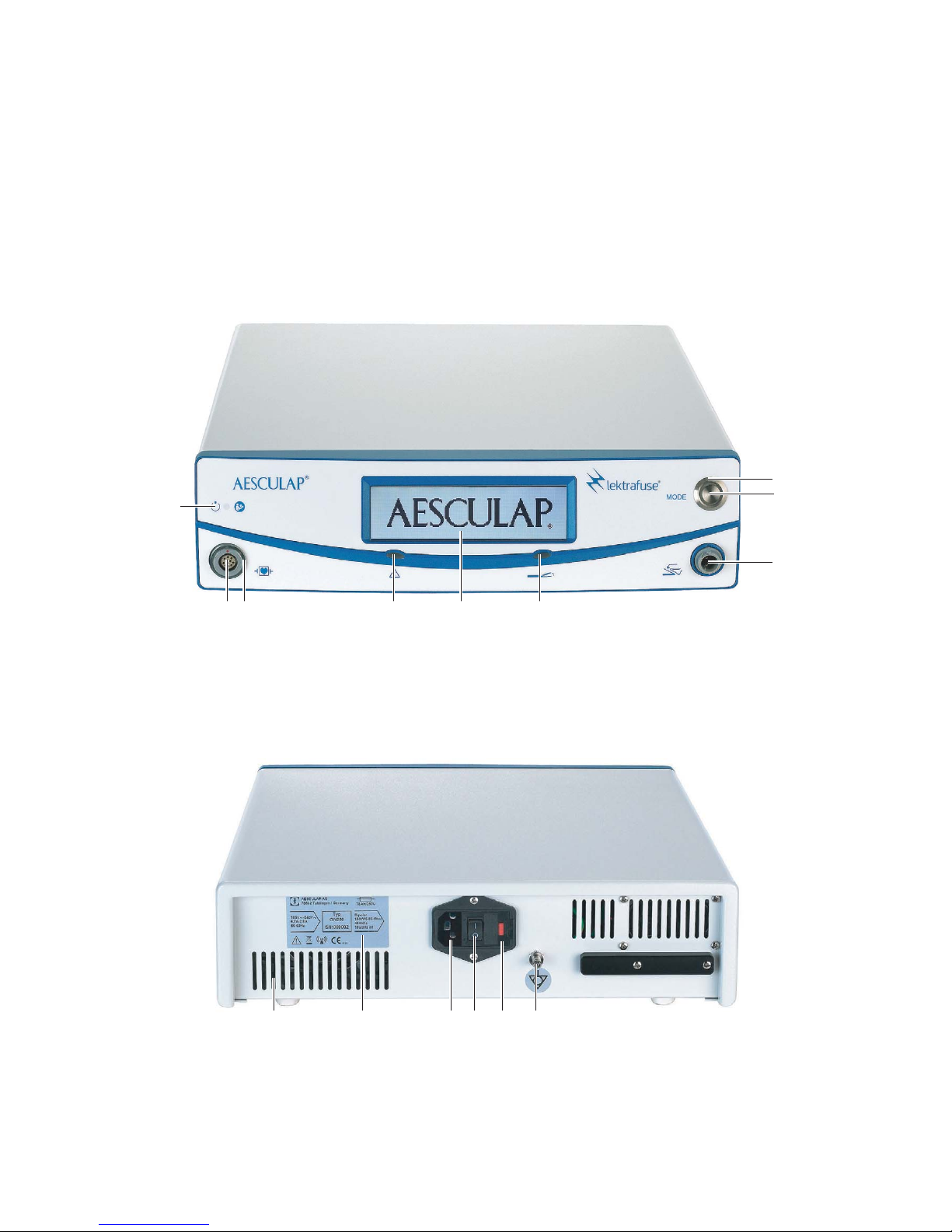
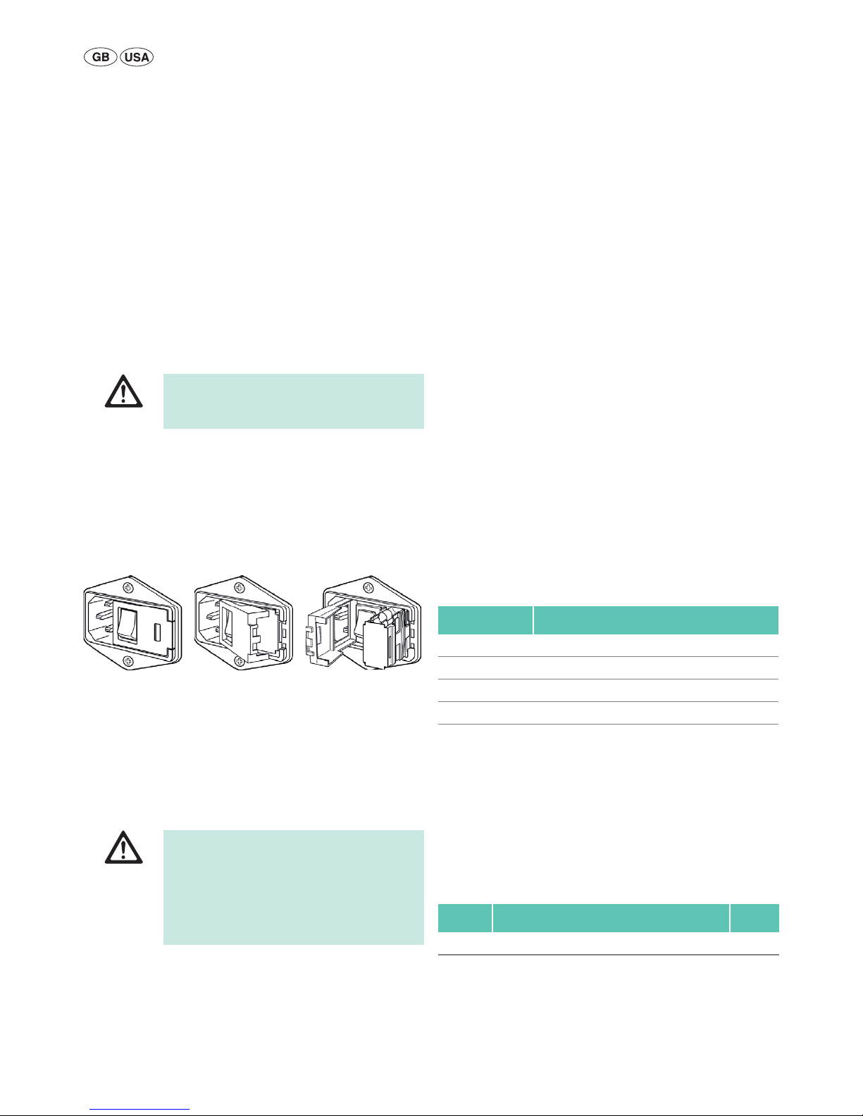
Legend
1 Signal lamp HF-ON (surrounding ring)
2 Operating mode selection button (MODE) (middle)
3 Connection socket (foot switch)
4 Signal lamp regrasp
5 Display
6 Signal lamp error
7 Signal ring instrument
8 Connection socket (instrument)
9 Indicator lamp power ON
10 Equipotential connector
11 Fuse holder (with 2 fuses)
12 OFF/ON switch
13 Mains power input socket
14 Type plate
15 Ventilation slots
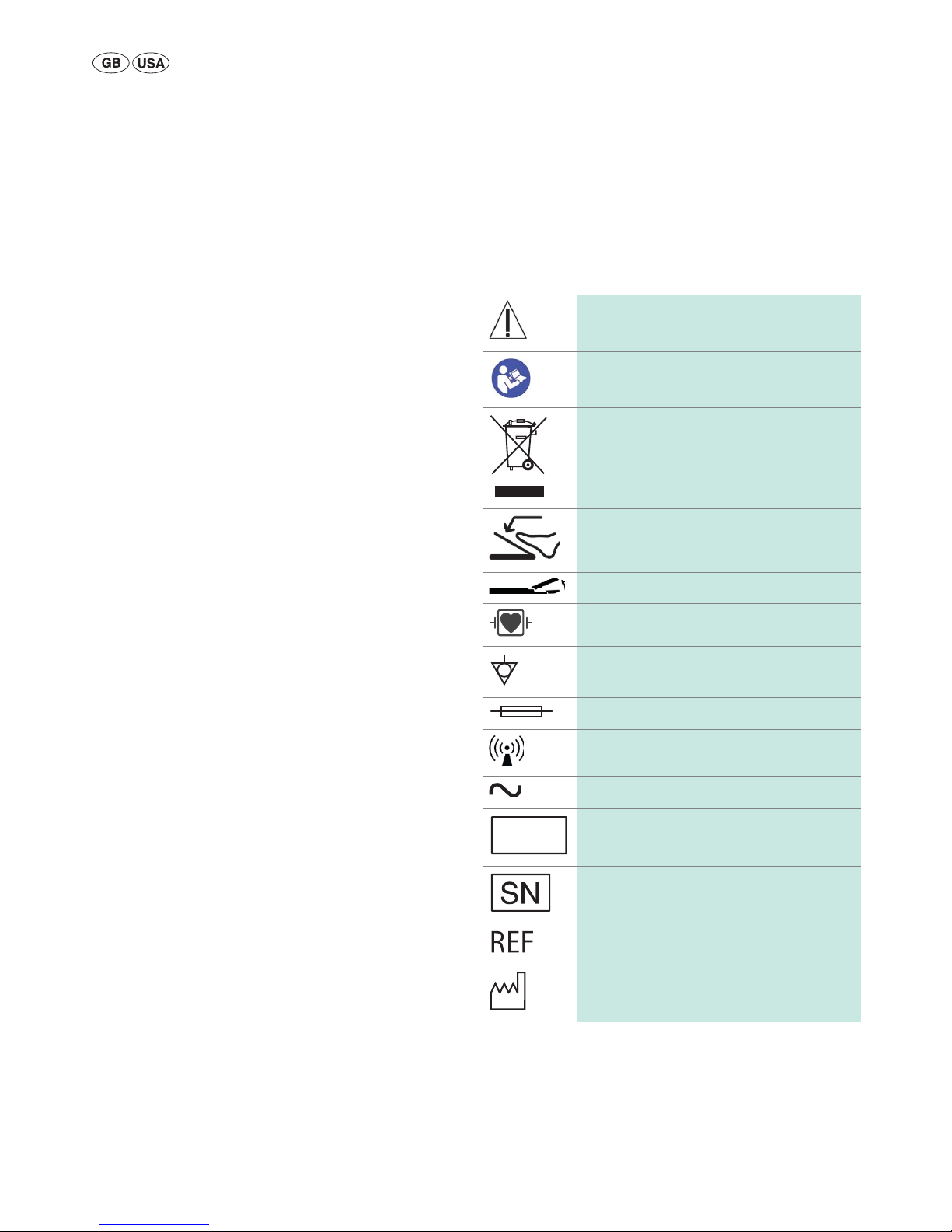
Symbols on product and packages
Caution
Observe important safety information such as warnings and precautions in the instructions for use.
Follow the instructions for use
Marking of electric and electronic devices according
to directive 2002/96/EC (WEEE), see Disposal
Foot switch
Regrasp
Type CF applied part, defibrillation-protected
Equipotentialization
Fuse
Non-ionizing radiation
Alternating current
Batch designation
Serial number
Order number
Date of manufacture
LOT
3
Contents
1. Safe handling 3
1.1 Safe for use in conformance with IEC regulations 4
2. Product description 5
2.1 Scope of supply 5
2.2 Components required for operation 5
2.3 Intended use 5
2.4 Operating principle 5
2.5 Acoustic warning signal 6
2.6 Monitoring functions 6
2.7 Output power diagrams 7
2.8 Maximum peak output voltage (Up) 7
3. Preparation and setup 7
3.1 First use 7
4. Working with the Lektrafuse HF generator GN200 8
4.1 System set-up 8
4.2 Function checks 10
4.3 Safe operation 10
5. Validated reprocessing procedure 11
5.1 General safety instructions 11
5.2 General information 11
5.3 Preparations at the place of use 11
5.4 Preparation before cleaning 11
5.5 Cleaning/disinfection 12
5.6 Wipe disinfection for electrical devices without sterilization 13
5.7 Inspection, maintenance and checks 13
5.8 Storage and transport 13
6. Maintenance 13
6.1 Safety inspection 13
7. Troubleshooting list 15
7.1 Regrasp error 15
7.2 Warnings 16
7.3 Error reports 16
7.4 Failure messages 17
7.5 Problem solving 17
7.6 User maintenance 18
7.7 Fuse replacement 18
8. Technical Service 18
9. Accessories/Spare parts 18
10. Technical data 18
10.1 Ambient conditions 19
11. Disposal 19
12. Distributor in the US/Contact in Canada for product
information and complaints 19
1. Safe handling
CAUTION
Federal law restricts this device to sale by or on order of a physician!
Note
These instructions for use only describe the set-up, function and operation
of the Lektrafuse generator GN200 and is not suitable for initiating a
beginner in high-frequency surgery.
Ŷ General risk factors associated with surgical procedures are not
described in this documentation.
Ŷ It is the operating surgeon's responsibility to ensure that the surgical
procedure is performed correctly.
Ŷ The operating surgeon must have a thorough understanding of both
the hands-on and conceptual aspects of the established operating
techniques.
Ź Transport the product only in its original box.
Ź Prior to use, check that the product is in good working order.
Ź Observe “Notes on Electromagnetic Compatibility (EMC)“, see
TA022130.
Ź The Lektrafuse HF generator GN200 fulfills the requirements of
CISPR 11, Class A.
Ź To prevent damage caused by improper setup or operation, and in order
not to compromise warranty and manufacturer liability:
– Use the product only according to these instructions for use.
– Follow the safety and maintenance instructions.
– Only combine Aesculap products with each other.
– Adhere to application instructions according to relevant norms, see
Safe for use in conformance with IEC regulations.
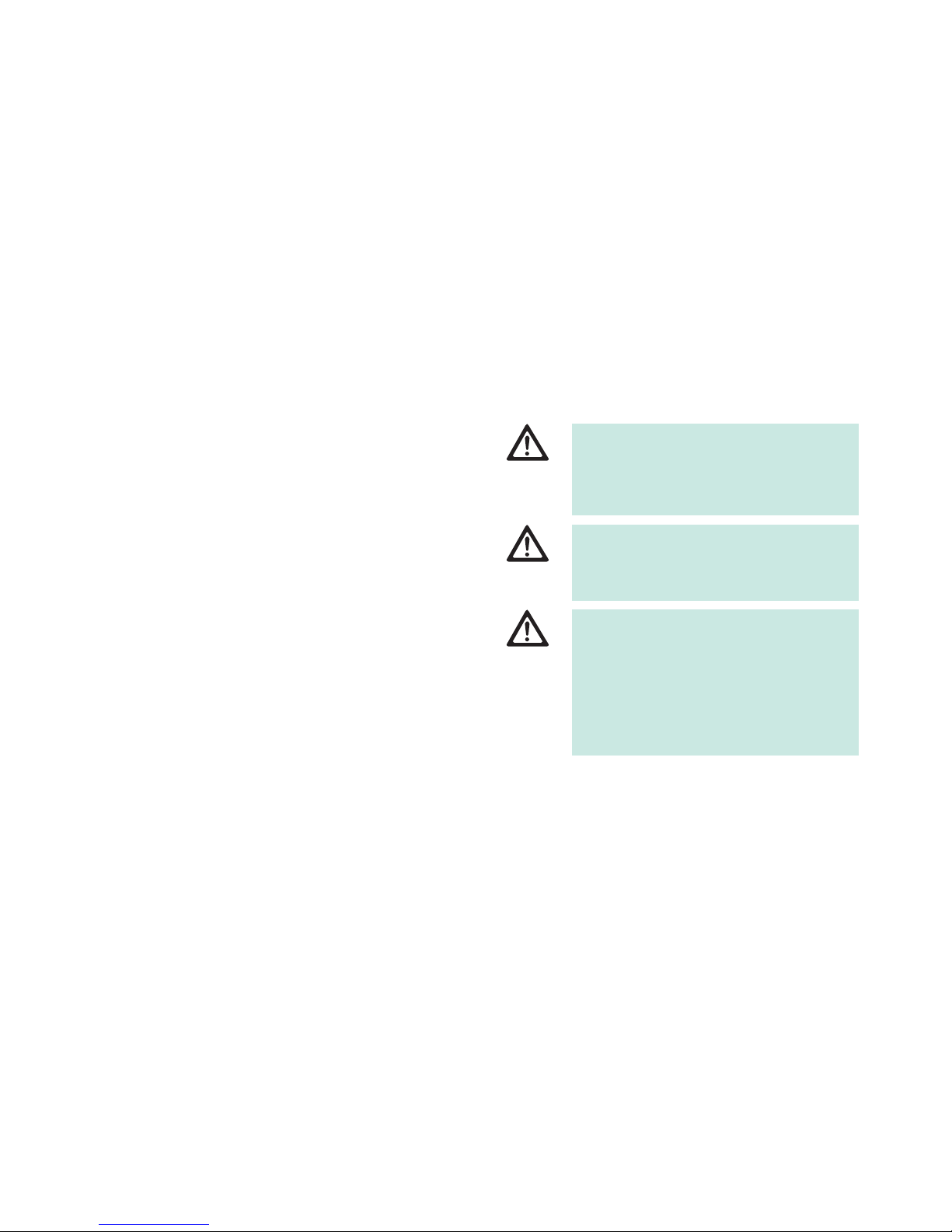
DANGER
Risk of injury to patients due to inappropriate
application!
Ź The product and accessories should only be
operated by qualified or trained and experienced personnel.
WARNING
Risk of injury and material damage due to inappropriate use of the product!
Ź Use the product only in accordance with the
intended use.
WARNING
Risk of injury and material damage due to improper
handling of the product!
The Lektrafuse HF generator together with the
accessories forms a system.
Ź Follow the instructions for use of the Lektrafuse
HF generator accessories.
Ź Follow the instructions for use of all products
used.
4
Aesculap®
Lektrafuse HF generator GN200
Ź Inspect the accessories regularly: Electrode cables and endoscopic
accessories, in particular, must be checked for possible damage to the
insulation.
Ź Keep the instructions for use accessible for the user.
Ź Always adhere to applicable standards.
1.1 Safe for use in conformance with IEC regulations
The operating environment
Ź Ensure that the device does not come in direct contact with the patient
or in the sterile area respectively.
Ź Ensure that the user does not come into direct contact with the patient
and HF generator at the same time.
Patient safety
DANGER
Risk of death by electric shock!
Ź Do not open the product.
Ź Only ever connect the product to power mains
with equipment grounding conductor.
WARNING
Risk of injury from ignition or explosion of flammable gases! Sparks may occur when using the HF
generator as directed.
Ź Do not use the device in explosion-hazard zones.
Ź When operating in the head or thoracic region,
avoid using combustible anesthetics and accelerating gases (e.g. nitrous oxide or oxygen) or,
when using such substances, ensure they are
extracted from the region of operation.
Ź If possible, use incombustible cleaning and dis-
infecting agents.
Ź If combustible cleaning and disinfecting agents
or solvents have to be used: Verify that such
agents have evaporated prior to commencing HF
surgery.
Ź Be sure that no inflammable liquids accumulate
under the patient’s body or in body cavities (e.g.
the vagina). Before using the HF generator, wipe
up all fluids.
Ź Ensure the absence of any endogenous, combus-
tible gases.
Ź Check that oxygen-soaked materials (e.g.
absorbent cotton or mull) are kept at a safe distance from the HF field, so that they cannot
ignite.
CAUTION
Risk of interference with other devices!
HF generators create potentially harmful magnetic
fields during normal use.
Ź Be sure that no electronic devices that could be
damaged by an electromagnetic field are set up
in the vicinity of the HF generator.
CAUTION
Restriction to view and/or side-effects due to the
development of steam/smoke during HF surgery!
Ź If necessary, use smoke suction.
DANGER
Danger to life from inadequate preparation or
operational errors in the HF generator!
Ź Be sure that the HF generator is in perfect
working order.
Ź Ensure that neither the foot switch nor the hand
switch has been penetrated by conductive fluids
(e.g. blood, amniotic fluid).
Ź Ensure there is no short circuit in the foot or
hand switch cables.
DANGER
Risk of burns suffered by the patient due to inadvertent activation of the HF generator!
Ź Switch off the HF generator immediately using
the power OFF/ON switch in the event that it is
activated accidentally.
Ź Always exercise particular care when operating
the foot switch.
DANGER
Risk of injury to the patient due to an unintended
rise of the HF output voltage due to a fault in the
HF generator!
Ź Stop using the HF surgical device as soon as it
shows even the slightest anomaly.
WARNING
Risk of injury to patients/users due to defective
power cord or missing protective ground connections!
Ź Check the mains power cord/protective ground
connections.
WARNING
Danger of injuries due to muscle contraction,
caused by stimulation of the nerves and muscles!
Ź Work with particular care on sensitive struc-
tures.

5
Always be sure to do the following:
Ź Position the patient in such a way that s/he is not in contact with any
metal parts that are grounded or have a significant electric capacity
against ground (e.g. operating table, fixtures). If necessary, interpose
antistatic drape.
Ź Ensure that the patient will not be in contact with any damp cloths,
drapes or bedding.
Ź Safeguard areas prone to strong perspiration against skin contact with
the trunk of the patient’s body by inserting antistatic tissue between
such areas and the trunk.
Ź Siphon off urine with a catheter.
Ź For heart surgery, ground the HF generator via the potential equaliza-
tion connection.
Ź For patients with cardiac pacemaker or other active implants, consult
with the relevant medical specialist prior to applying HF surgery, so
that irreparable damage to the pacemaker or implant can be avoided.
Ź If possible, remove from the vicinity of HF electrodes any electrodes
from physiological monitoring devices that are not equipped with protective resistors or HF dampers.
Ź Do not use needle electrodes for intraoperative monitoring.
Ź Arrange the wires and cables of monitoring devices in such a way that
they do not come in contact with the patient’s skin.
Ź Keep the leads to the HF electrodes as short as possible, and arrange
them in such a way that they do not touch the patient or any other
wires or cables.
Ź Should the output power appear insufficient with the usual settings,
check that:
– the working electrodes are clean,
– all plug connections are properly in place.
Ź Never lay active electrodes on or next to the patient.
Ź Put down active electrodes that are not needed at any particular
moment, in such a way that they will not touch the patient.
Ź For operations involving unavoidable, continuous contact between the
electrodes and the patient (e.g. endoscopic procedures), press the
power OFF/ON switch 12 to switch off the HF generator immediately
after any inadvertent activation of the electrode.
Ź Do not remove hot electrodes from the patient’s body immediately
after performing cutting or coagulation procedures.
Ź During operation of the generator, do not touch the electrodes on the
instrument (on the upper or lower side) as the electrodes can heat up
and this may lead to burns or injuries.
2. Product description
2.1 Scope of supply
2.2 Components required for operation
Ŷ Power cord
Ŷ Foot switch (optional)
Ŷ Caiman Instrument
2.3 Intended use
The Lektrafuse HF generator GN200 is used for vessel sealing and vessel
division in open and minimally invasive surgery. The instruments can seal
vessels of up to and including 7 mm.
The Lektrafuse HF generator is not suitable for use in tube sterilization/tube coagulation for sterilization.
With respect to the electric shock hazard, the Lektrafuse HF generator
meets the classification and safety requirements of a type CF device.
The Lektrafuse HF generator is intended only for indoor operation and
storage.
2.4 Operating principle
The Lektrafuse HF generator GN200 works on a micro-processor controlled basis and converts the voltage of the mains supply into a high-frequency alternating current for bipolar vessel sealing.
The sealing process is carried out via a closed control circuit. The sealing
can be started and stopped via a button on the instrument or a foot
switch.
The Lektrafuse HF generator GN200 has two operating modes:
Ŷ Standard mode: Pre-set operating mode
Ŷ Plus mode: Operating mode with increased energy output
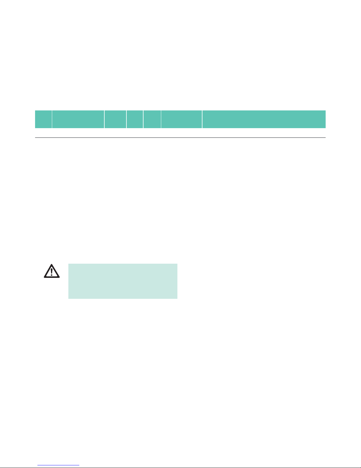
Designation Art. no.
High frequency surgical device GN200
Instructions for use TA022414
Notes on Electromagnetic Compatibility TA022130
6
Aesculap®
Lektrafuse HF generator GN200
2.5 Acoustic warning signal
2.6 Monitoring functions
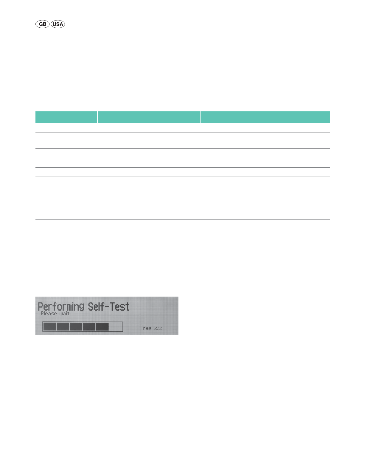
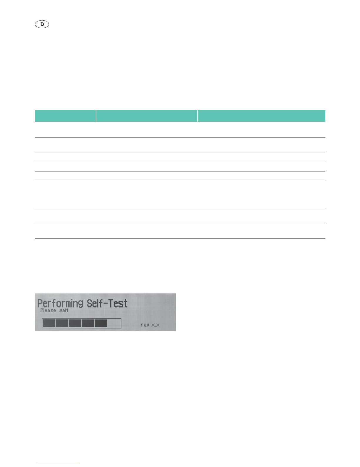
Self-test
As soon as it is switched on, the unit performs a self-test of the control
elements, the acoustic warning signal, the microprocessor and the hardware function. During this phase, the message "Performing Self-Test"
appears in the display 5.
Fig.1
Continuous test cycle during operation
During operation, safety-relevant functions and signals are monitored
through a continuous test cycle. As soon as a critical error is detected, the
HF generator terminates the HF activation. In display 5, the error number
of the corresponding error is displayed and an acoustic warning signal is
emitted, see Troubleshooting list.
Status Acoustic warning signal Notes
System failure 3 repetitions of: 1 long beep, 3 KHz, 1 beep, 2 KHz Following each system failure, if identified (F001,...)
REGRASP error 3 repetitions of: 1 beep, 2 KHz,
1 beep, 3 KHz
Following each regrasp error, if identified
System error 3 beeps, 3 KHz Following each failure report, if identified (E001,...)
System warning 3 beeps, 3 KHz Following each warning, if identified
Start HF discharge 2 beeps, 480 Hz When starting the HF discharge
HF discharge active 1 beep, 480 Hz
Ŷ In Standard mode: Repetition with 1.8 Hz
Ŷ In Plus mode: Repetition with 2.8 Hz
Continually during HF discharge
End of HF discharge 3 beeps, 530 Hz When a sealing process has been successfully completed (no
failure reports or errors)
Power up self-test 1 beep, 2 KHz During the self-test, in order to check that the signal tone is
functioning
7
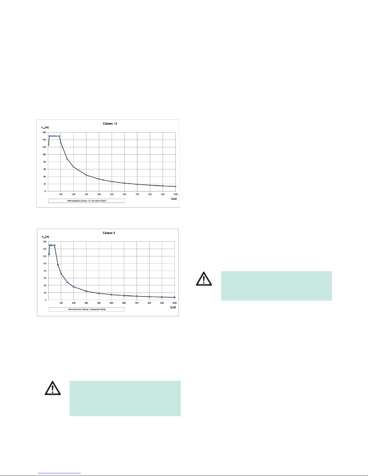
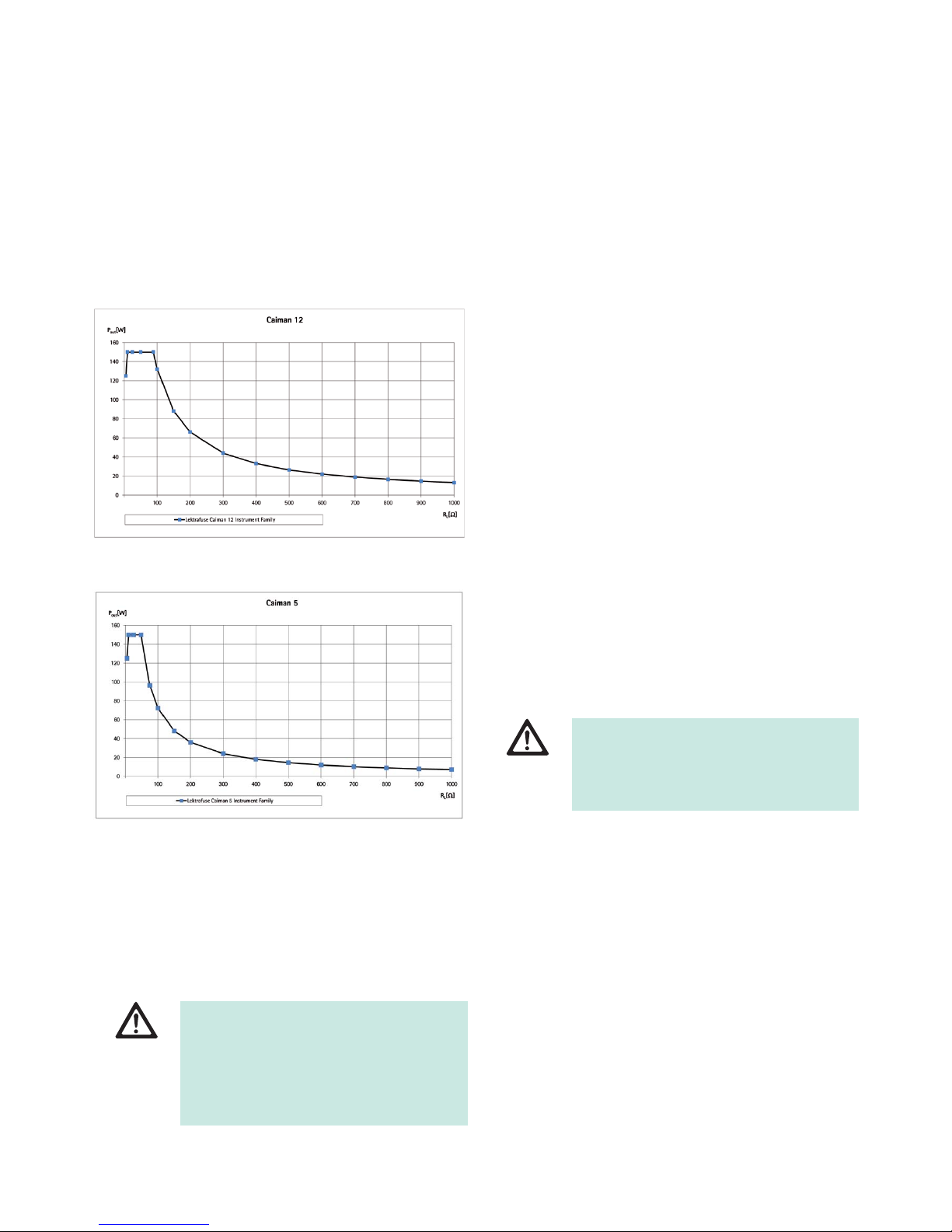
2.7 Output power diagrams
Representation of the output power as a function of the load resistance.
Fig.2 Output power diagram Caiman 12 mm Seal & Cut instrument
family
Fig.3 Output power diagram Caiman 5 mm Seal & Cut instrument
family
2.8 Maximum peak output voltage (Up)
Note
The following data allow the user to judge whether the HF generator
GN200 is suitable for a given accessory (insulation rating).
Maximum peak output voltage (Up): 200 V
3. Preparation and setup
Non-compliance with the following instructions will preclude all responsibility and liability in this respect on the part of Aesculap.
Ź When setting up and operating the product, adhere to
– national regulations for installation and operation,
– national regulations on fire and explosion protection.
Note
For the safety of patients and users it is essential that the mains power cord
and, especially, the protective earth connection are intact. In many cases
defective or missing protective earth connections are not registered immediately.
Ź Connect the device via the potential equalization terminal at the rear
panel of the device to the potential equalization system of the room
used for medical purposes.
Note
The potential equalization lead can be ordered from the manufacturer as
article no. GK535 (4 m length) or TA008205 (0.8 m length).
Ź In order to ensure sufficient ventilation and cooling of the HF genera-
tor, leave at least 10 cm to 15 cm of space around the HF generator.
3.1 First use
WARNING
Risk of injury to patient or user caused by inadequate accessories (insulation rating)!
Ź Make certain that the accessory voltage rating
specified in the product documentation is
higher than maximum peak output voltage.
WARNING
Risk of injury and/or product malfunction due to
incorrect operation of the electromedical system!
Ź Adhere to the instructions for use of any medi-
cal device.
8
Aesculap®
Lektrafuse HF generator GN200
4. Working with the Lektrafuse HF gener-
ator GN200
4.1 System set-up
Connecting the accessories
Combinations of accessories that are not mentioned in the present
instructions for use may only be employed if they are specifically intended
for the respective application, and if they do not compromise the performance and safety characteristics of the products.
Only CAIMAN instruments can be used in conjunction with the Lektrafuse
HF generator GN200, see Accessories/Spare parts.
Connecting the power supply
The voltage of the mains power supply must correspond to the voltage
indicated on the type plate of the device.
The device is fitted with a universal power supply unit, which means that
it automatically adapts to mains voltages ranging from 100 V to 240 V
without having to switch between voltage ranges.
Ź Ensure that the device is switched off. If necessary, switch off with the
power OFF/ON switch 12.
Ź Plug in the power cord in mains power input socket 13 in the rear
panel of the HF surgical device.
Ź Plug in the mains plug at the building mains power socket.
Switching on the device
Ź Switch on the device with the power OFF/ON switch 12.
Indicator lamp power ON 9 is illuminated. The device performs a selftest, see Continuous test cycle during operation:
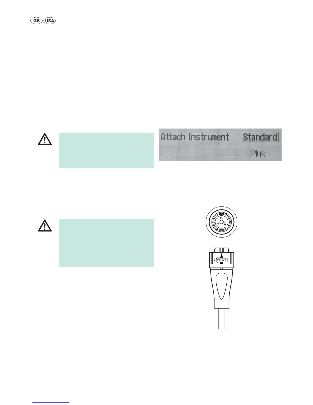
If no instrument is connected, the message "Attach Instrument"
appears in the display 5 after the self-test. If the self-test fails, an error
message is shown in the display 5.
Fig.4
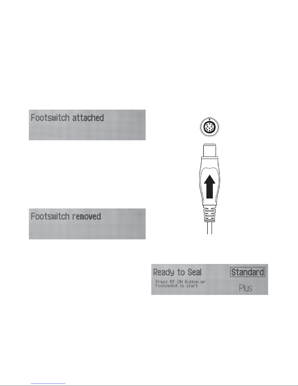
Connecting the foot switch
Connecting the foot switch GN201 is optional.
Both the foot switch plug and connection socket (foot switch) 3 have a
dot marking. To connect the plug to the connection socket correctly, these
markings must be aligned.
Fig.5
DANGER
Risk of injury due to unapproved configuration
using additional components!
Ź For all applied components, ensure that their
classification matches that of the application
component (e.g. Type BF or Type CF) of the
respective device.
DANGER
Risk of death from electric shock!
Ź Only connect the product to power mains with
equipment grounding conductor.
Ź Set up the device in a way that switching it off
using the power OFF/ON switch is possible and
straightforward.
Ź Set up the device in a way that disconnecting
the power cord is straightforwardly possible.
9
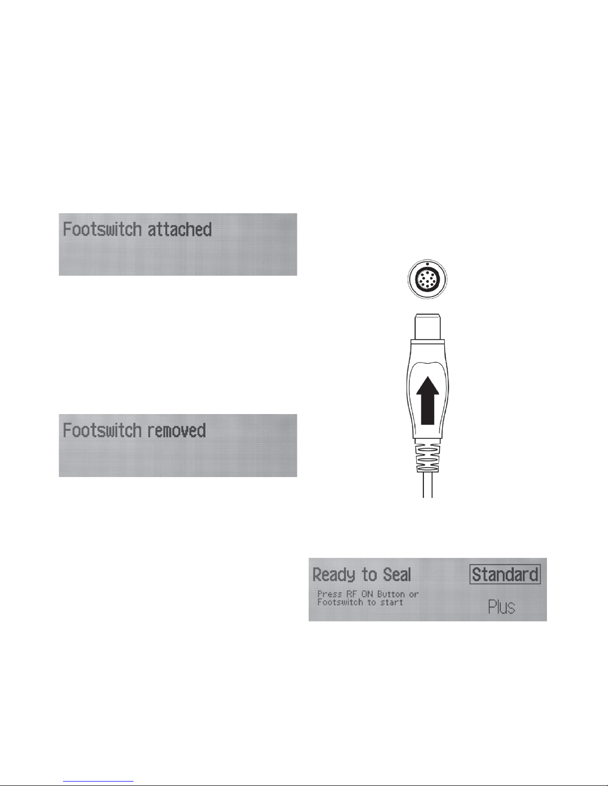
Ź Align the foot switch plug and insert it into the foot switch connection
socket 3 until it engages.
When the device and the foot switch have been successfully con-
nected, the message "Footswitch attached" appears for 3 seconds in
the display 5.
Fig.6
Note
Do not activate the foot switch continually during HF discharge. HF discharge is started and stopped by pressing once on the foot switch and then
releasing.
Remove the foot switch
Ź Turn the locking ring counter-clockwise and withdraw the connecting
plug at the same time
The message "Footswitch removed" appears in the display 5 for 3 sec-
onds.
Fig.7
Connecting the instrument
Only instruments of the CAIMAN Seal & Cut product family can be used
in conjunction with the Lektrafuse HF generator GN200.
The instrument connector has an arrow marking and the connection
socket 8 has a dot marking. To connect the plug to the connection socket
correctly, these markings must be aligned.
Fig.8
Ź Connect the instrument with the connection socket 8.
The green signal ring 7 around the instrument connector lights up. The
message "Ready to Seal" appears in the display 5.
Fig.9
10
Aesculap®
Lektrafuse HF generator GN200
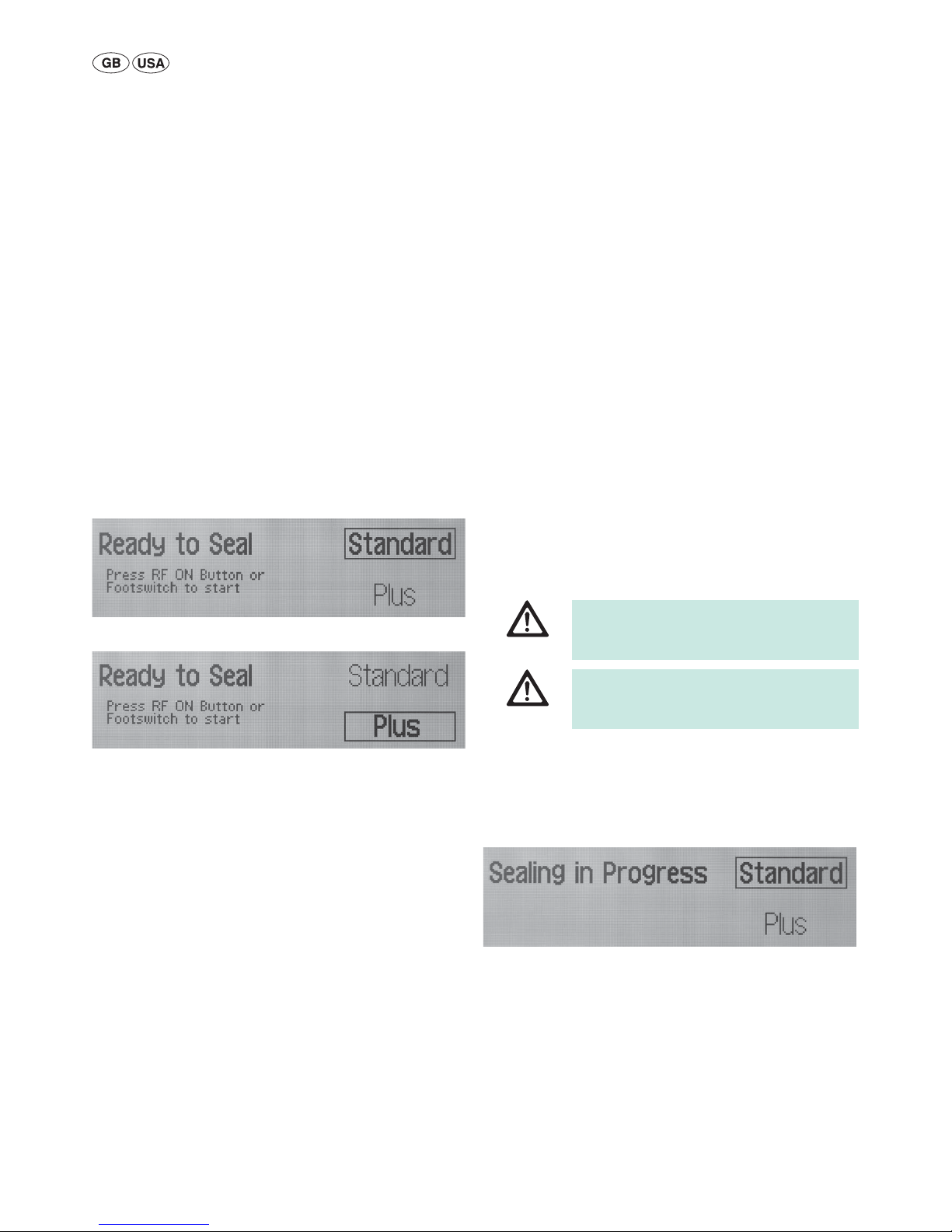
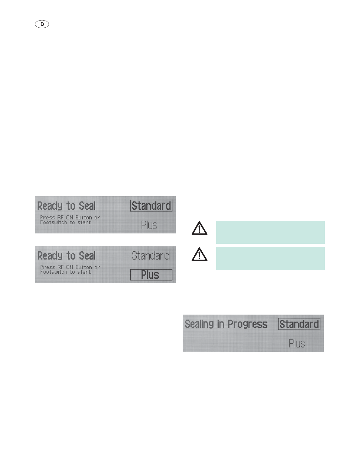
Selecting the operating mode
The Lektrafuse HF generator has two operating modes for the sealing process. The selected operating mode will be retained until the HF generator
is switched off. The operating mode can be changed during the procedure.
Ź Changing the operating mode: Press operating mode selection button
(MODE) 2.
Ŷ Standard mode: Pre-set operating mode
Ŷ Plus mode: Operating mode with increased energy output
The operating mode is independent from the connected instrument.
Changing or reconnecting the instrument does not change the operating
mode.
The active operating mode is indicated in the display as follows:
Ŷ Border
Ŷ Bold font
Fig.10
Fig.11
Note
In case of a regrasp error, the active operating mode is not displayed. The
active operating mode can be displayed by pressing the operating mode
selection button (MODE) 2.
Note
The Plus mode can be distinguished from Standard mode by the higher frequency of the beep during HF discharge.
Shutting down
Ź Switch off the device with the power OFF/ON switch 12.
All the poles of the device are disconnected from the power supply.
Ź Withdraw mains cable.
The device is completely disconnected from the power supply.
4.2 Function checks
Prior to each use, carry out a functional test of the device:
Ź Check that the accessories have no visible damage.
Ź Prepare and set up the unit, see Preparation and setup.
Ź Check the functionality of the following elements, one after the other,
in the following sequence:
– Switch on the power OFF/ON switch 12; the power on signal
lamp 9 lights up
– Automatic self-test after each time the device is switched on: brief
acoustic signal, all display elements light up briefly
– Operating mode selection, see Selecting the operating mode
– foot switch, see Connecting the foot switch
– Instrument, see Connecting the instrument
– Activation with instrument button and foot switch
– Switch off the power OFF/ON switch 12
4.3 Safe operation
Ź Start the sealing process (HF discharge) by pressing the button on the
instrument or foot switch once.
After completing the sealing process, the HF discharge is automatically
stopped.
During sealing process, the message "Sealing in Progress" is shown on
the display 5.
Fig.12
To activate/deactivate device
Ź Switch on/switch off the device with the power OFF/ON switch 12.
Operating mode
The Lektrafuse HF generator GN200 automatically recognizes the connected instrument. The internal device settings are loaded. The user can
choose between two operating modes.
WARNING
Risk of injury and/or malfunction!
Ź Always carry out a function check prior to using
the product.
WARNING
Risk of injury when using the product beyond the
field of view!
Ź Apply the product only under visual control.

11
Activating the HF current
Ź Be sure that the patient is prepared in such a way that the HF genera-
tor can be applied without any risk to the patient.
Ź Make sure that the required operating mode is selected.
Ź Ensure that the instrument and foot switch, if used, are correctly con-
nected.
Ź Activate the HF generator via the hand switch or the foot switch.
Ź Do not activate the hand switch or foot switch continually during HF
discharge.
Note
The vessel sealing process is started and ended by pressing the foot switch
or hand switch on the instrument once. After completing the sealing process, the device stops the HF discharge automatically. The sealing process
can be interrupted by pressing the button once more.
5. Validated reprocessing procedure
5.1 General safety instructions
Note
Adhere to national statutory regulations, national and international standards and directives, and local, clinical hygiene instructions for sterile processing.
Note
For patients with Creutzfeldt-Jakob disease (CJD), suspected CJD or possible variants of CJD, observe the relevant national regulations concerning
the reprocessing of products.
Note
Mechanical reprocessing should be favored over manual cleaning as it
gives better and more reliable results.
Note
Successful processing of this medical device can only be ensured if the processing method is first validated. The operator/sterile processing technician is responsible for this.
The recommended chemistry was used for validation.
Note
If there is no final sterilization, then a virucidal disinfectant must be used.
Note
For up-to-date information about reprocessing and material compatibility,
see also the Aesculap Extranet at https://extranet.bbraun.com.
The validated steam sterilization procedure was carried out in the Aesculap
sterile container system.
5.2 General information
Dried or affixed surgical residues can make cleaning more difficult or ineffective and lead to corrosion. Therefore the time interval between application and processing should not exceed 6 h; also, neither fixating precleaning temperatures >45 °C nor fixating disinfecting agents (active
ingredient: aldehydes/alcohols) should be used.
Excessive measures of neutralizing agents or basic cleaners may result in
a chemical attack and/or to fading and the laser marking becoming
unreadable visually or by machine for stainless steel.
Residues containing chlorine or chlorides e.g. in surgical residues, medicines, saline solutions and in the service water used for cleaning, disinfection and sterilization will cause corrosion damage (pitting, stress corrosion) and result in the destruction of stainless steel products. These must
be removed by rinsing thoroughly with demineralized water and then drying.
Additional drying, if necessary.
Only process chemicals that have been tested and approved (e.g. VAH or
FDA approval or CE mark) and which are compatible with the product’s
materials according to the chemical manufacturers’ recommendations
may be used for processing the product. All the chemical manufacturer's
application specifications must be strictly observed. Failure to do so can
result in the following problems:
Ŷ Optical changes of materials, e.g. fading or discoloration of titanium or
aluminum. For aluminum, the application/process solution only needs
to be of pH >8 to cause visible surface changes.
Ŷ Material damage such as corrosion, cracks, fracturing, premature aging
or swelling.
Ź Do not use metal cleaning brushes or other abrasives that would dam-
age the product surfaces and could cause corrosion.
Ź Further detailed advice on hygienically safe and material-/value-pre-
serving reprocessing can be found at www.a-k-i.org, link to Publications, Red Brochure – Proper maintenance of instruments.
5.3 Preparations at the place of use
Ź Remove any visible surgical residues to the extent possible with a
damp, lint-free cloth.
Ź Transport the dry product in a sealed waste container for cleaning and
disinfection within 6 hours.
5.4 Preparation before cleaning
Ź Disconnect the unit from mains power.
Ź Remove accessories.

12
Aesculap®
Lektrafuse HF generator GN200
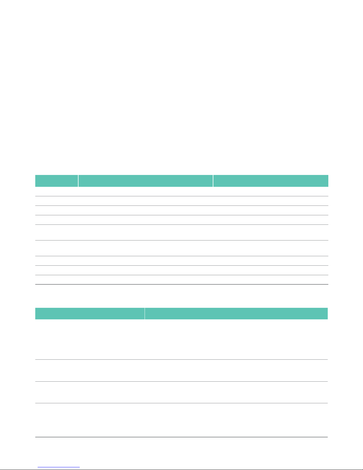
5.5 Cleaning/disinfection
Product-specific safety instructions for the reprocessing procedure
Validated cleaning and disinfection procedure
DANGER
Risk of electric shock and fire hazard!
Ź Unplug the device before cleaning.
Ź Do not use flammable or explosive cleaning or
disinfecting solutions.
Ź Ensure that no fluids will penetrate the product.
CAUTION
Damage to, or destruction of the product caused by
mechanical cleaning/disinfection!
Ź Only clean and disinfect the product manually.
Ź Do not sterilize the product under any circum-
stances.
CAUTION
Damage to the product due to inappropriate cleaning/disinfecting agents!
Ź Only use cleaning/disinfecting agents approved
for surface cleaning. Follow the manufacturer’s
instructions for the respective cleaning/disinfecting agent.
CAUTION
Damage to the product due to inappropriate cleaning/disinfecting agents and/or excessive temperatures!
Ź Use cleaning agents and disinfectants according
to the manufacturer's instructions.
Ź Observe specifications regarding concentration,
temperature and exposure time.
Validated procedure Special features Reference
Wipe disinfection for
electrical devices without sterilization
– Chapter Wipe disinfec-
tion for electrical devices
without sterilization
13
5.6 Wipe disinfection for electrical devices without sterilization
RT: Room temperature
Phase I
Ź Remove any visible residues with a disposable disinfectant wipe.
Ź Wipe all surfaces of the optically clean product with a fresh, disposable
disinfectant wipe.
Ź Observe the specified application time (1 min minimum).
5.7 Inspection, maintenance and checks
Ź Inspect the product after each cleaning and disinfecting cycle to be
sure it is: clean, functional, and undamaged.
Ź Set aside the product if it is damaged.
Ź Perform a safety inspection annually, see Maintenance.
5.8 Storage and transport
Ź Transport the product only in its original box.
Ź For storage and transport conditions, see Ambient conditions.
6. Maintenance
No servicing is required for the Lektrafuse HF generator GN200.
Note
Maintenance must only be carried out by authorized personnel. If necessary, the circuit diagrams and the service manual, which contains all the
necessary documents, are provided for this.
6.1 Safety inspection
A safety inspection must be carried out annually.
The person in charge of the inspection will document the inspection find-
ings and measurement values according to the printed inspection protocol.
Ź Only have the product and its accessories inspected by persons who
possess the requisite training, knowledge and experience and who are
authorized to do so.
Ź If there are significant deviations from the inspection protocol values,
or if the prescribed maximum values are exceeded: Send in the device.
For technical service, please contact your national B. Braun/Aesculap
agency, see Technical Service.
Phase Step T
[°C/°F]t[min]
Conc.
[%]
Water quality Chemical
IWipe disinfectionRT 1 - - Meliseptol HBV wipes 50 % Propan-1-ol
CAUTION
Damage to the product caused by switch-on too
early after storage/transport at temperature below
+10 °C (50 °F)!
Ź Allow the HF generator to acclimate at room
temperature for about 1 hour.

14
Aesculap®
Lektrafuse HF generator GN200
Fig.13 Inspection protocol form Safety inspection
Inspection protocol – safety inspection
TEST INTERVAL: 1 Year
TYPE OF DEVICE:
MANUFACTURED BY:
Bipolar Electrosurgical Unit GN200
Aesculap AG, Am Aesculap-Platz 78532 Tuttlingen/Germany
SN: ...............................
INVENTORY NO.:
...............................
RESPONSIBLE
ORGANIZATION: ..........................................................................
Measurement
equipment: ...........................................................................................................................................................................................
tcidreV NOITCEPSNI FO EPOCS
1.) VISUAL INSPECTION
PASS FAIL
1.1 Inspection of power cable for visually detectable damage
1.2 Inspection of foot switch for visually detectable damage
elbadaer dna tneserp llits etalp epyT 3.1
1.4 Check fuse links for prescribed values
1.5 Overall condition of device: dirt, damage
2.) ELECTRICAL INSPECTION
Measured value
Verdict
Pass / Fail
2.1
Protective earth resistance incl. mains cable
according IEC62353:2007
R
max
=0,3 Ω (at ≥0,2 A)
2.2
Earth leakage current
according IEC60601-1*
N.C.
S.F.C.
I
max
= 0,50 mA
I
max
= 1,00 mA
2.3
Enclosure leakage current/touch current
according IEC60601-1*
N.C.
S.F.C.
I
max
= 0,10 mA
I
max
= 0,50 mA
2.4
Patient leakage current
according IEC60601-1*
N.C.
S.F.C.
I
max
= 0,01 mA
I
max
= 0,05 mA
2.5
Equipment leakage current - alternative method
according IEC62353:2007
I
max
= 1,00 mA
2.6
Applied part leakage current - alternative method
according IEC62353:2007
I
max
= 0,05 mA
2.7 HF-leakage current bipolar
according IEC60601-2-2:2009
I
max
= 122mA
2.8 Insulation resistance
according IEC62353:2007 (Preparation according Service Manual)
test voltage = 500 V DC
tuptuo FH tsniaga sniaM 1.8.2
R
min
= 7 MΩ
gnisuoh tsniaga sniaM 2.8.2
R
min
= 2 MΩ
gnisuoh tsniaga tuptuo-FH 3.8.2
R
min
= 2 MΩ
2.9 HF-output power measurement with induction-free resistor
Instrument Channel R
Load
Rated value
05 1 5C
Ω
145 Watt
±
20 %
C24/44 1 50
Ω
150 Watt
±
20 %
05 2
Ω
150 Watt
±
20 %
2.10 DC resistance between the two HF output poles
according IEC60601-2-2:2009 section 201.8.4.102
R
min
= 2 MΩ
2.11
Function test according to instructions for use
Performed:
TLUSER TSET
Deficiencies were determined, by which patient, user or other individuals can be endangered
No Yes
Repair …………………………………………………….. Next date of inspection
erutangiS/rotcepsnI etaD/ecalP Responsible Organization
* The listed allowable values comply with the requirements of the IEC60601-1:1988+A1:1991+A2:1995 and IEC60601-1:2005

15
7. Troubleshooting list
7.1 Regrasp error
A regrasp error, i.e. potentially insufficient sealing of the vessels, is displayed as follows:
Ŷ Unambiguous sound sequence and interruption of the sound sequence
of HF operation, also stops HF discharge
Ŷ The yellow regrasp error light 4 on the front side of the HF generator
lights up
Ŷ Warning message in the display 5 on the front side of the HF generator
Procedure if a regrasp error occurs:
Ź Do not cut the vessel.
Ź Open the instrument.
Ź Check the sealed vessel.
When correct hemostasis has occurred:
Ź Cut the vessel manually with surgical scissors.
When hemostasis has not occurred in the correct way:
Ź Place the instrument on the vessel again and lock it in place.
Note
The regrasp error must not be confirmed. Activating the hand switch or foot
switch will start the next sealing process immediately.
Note
In case of a regrasp error, the active operating mode is not displayed. The
active operating mode can be displayed by pressing the operating mode
selection button (MODE) 2.
Ź Start additional HF cycle.
Ź If the additional HF cycle leads to a normal seal, the vessel can be cut,
and the instrument can be opened and removed.
Ź If a regrasp error occurs again, do not cut the vessel, open the instru-
ment and manually cut the sealed vessel with surgical scissors. When
so doing, ensure that the hemostasis is correct.
Regrasp error message Significance Remedy
REGRASP INDICATOR – OPEN
Visually check seal – Manually cut
- Clean jaws
OR
Regrasp thicker tissue
Check the vessel sealing. Contact areas of the jaw part
must be covered with dried vessel residue or bodily fluids.
- or The gripped bundle of tissue is too thin
Clean contact areas with sterile water and
a sponge
Grip a thicker tissue bundle
REGRASP INDICATOR – SHORT
Visually check seal – Manually cut
Check for metal or occlusion in jaw
Remove excess fluids
There is metal (e.g. staples) or other foreign material
between the electrodes in the jaw part
Open and check jaw part
Remove any foreign material
Remove excess suction fluids in the operating area
REGRASP INDICATOR – TIME
Visually check seal – Reseal as needed
Seal cycle interrupted
Seal endpoint not reached
HF generator has reached its maximum sealing time and
has not ascertained any complete seal
- or The user has ended HF discharge during sealing
Check the quality of the seal

16
Aesculap®
Lektrafuse HF generator GN200
7.2 Warnings
A warning is indicated as follows:
Ŷ Individual tone (different from a failure, an error or normal HF opera-
tion)
Ŷ Warning message in the display 5 on the front side of the HF generator
7.3 Error reports
An error is indicated as follows:
Ŷ Unambiguous tone sequence (different from a failure or normal HF
operation)
Ŷ Failure message in the display 5 on the front side of the HF generator
Warning message Significance Remedy
Generator Cooling
Please Wait
generator temperature too high Check the airflow around the generator
Generator Too Cold
Please Wait
Generator must first warm up Do not switch off the generator whilst it is warming up
Error code Error report Significance Remedy
E001 ERROR E001
Instrument HF activation button error
Release Instrument RF-ON Button
Remove and reattach instrument
Instrument "HF activation" button is
pressed while the instrument is connected to the HF generator
Release the “HF activation" button
Remove instrument and reconnect it
E002 ERROR E002
Instrument Error
Remove and reattach OR
Remove and replace instrument
HF generator cannot find instrument
- or Instrument is defective and must be
replaced
Remove instrument and reconnect it
- or Replace instrument
E003 ERROR E003
Footswitch Error
Release footswitch
Remove and reattach footswitch
Foot switch is pressed while the foot
switch is connected to the HF generator
Release foot switch
Remove foot switch and reconnect it
17
7.4 Failure messages
A failure is indicated as follows:
Ŷ Clear sound sequence (as necessary, may interrupt the sound of the HF
discharge)
Ŷ The red error light 6 on the front side of the HF generator lights up
Ŷ Error message in the display 5 on the front side of the HF generator
Note
If the failure occurs during HF discharge, the vessel sealing may be incomplete or insufficient.
In order to ensure that sufficient hemostasis has been achieved, follow the
procedure for regrasp errors, see Regrasp error.
Note
If the failure continues after turning the device off and on again twice, contact your national B. Braun/Aesculap agency, see Technical Service.
7.5 Problem solving
Failure code Cause Remedy
F001 Software error on the HF generator Switch off HF generator, wait 5 s, switch HF generator on
F002 Dosage error of HF generator Switch off HF generator, wait 5 s, switch HF generator on
F003 Hardware error Switch off HF generator, wait 5 s, switch HF generator on
F004 Internal communication error of the HF generator Switch off HF generator, wait 5 s, switch HF generator on
F005 Overheating of HF generator Switch off HF generator and leave to cool down
Check the air stream around the generator
F006 Error in the operating mode selection button (MODE) 2 (activated
when switching on)
Switch off HF generator, wait 5 s, release operating mode
selection button (MODE) 2, switch HF generator on
F007 Error with HF energy output Switch off HF generator, wait 5 s, switch HF generator on
F008 Fault: HF outside the calibration Switch off HF generator, wait 5 s, switch HF generator on
F009 Fault: Internal power supply Switch off HF generator, wait 5 s, switch HF generator on
Finding Remedy
HF generator does not switch on Ensure that the power cord has been correctly plugged into the power supply 13 of the HF
generator.
Ensure that the power cord is connected to a functioning power source.
Ensure that the power OFF/ON switch 12 of the HF generator is in the power ON position.
Check the fuse in the fuse box and replace if necessary, see Fuse replacement.
If the error continues, replace power cord.
The device is switched on, but no displays are illuminated and the self-test is not being carried out
Switch off HF generator, wait 5 s, switch HF generator on again.
If the error continues, contact your national B. Braun/Aesculap agency, see Technical Service.
Self-test fails Switch off HF generator, wait 5 s, switch HF generator on again.
If the error continues, contact your national B. Braun/Aesculap agency, see Technical Service.
HF generator is active (power ON signal lamp 9 lights
up), and accessories are connected, but there is no HF
discharge
Verify that the required foot switch (if used ) is properly connected and plugged in.
Ensure that the Caiman Seal & Cut Instrument is correctly connected and plugged in (green
ring 1 is lit up).
In order to start the HF discharge, activate the button on the instrument or the foot switch.
If the error continues, replace Caiman instrument.
18
Aesculap®
Lektrafuse HF generator GN200
7.6 User maintenance
Ź In case of error, follow the instructions in the display and note the error
code.
Ź If the error continues after following the instructions in the display,
contact your national B. Braun/Aesculap agency, see Technical Service.
7.7 Fuse replacement
Specified fuses: 2 units Aesculap art. no. TA021404:
G fuse link, time lag (T) 8 A, breaking capacity H (1 500 A)
Ź Use a small screwdriver to release the clip on the fuse holder 11 and
tilt up cover.
Ź Use a small screwdriver to release the fuse holder 11 and pull it out.
Ź Replace both fuses.
Ź Reinsert the fuse holder 11.
Ź Close the cover.
Fig.14
Note
If the fuses burn out frequently, the device is faulty and should be
repaired, see Technical Service.
8. Technical Service
Ź For service and repairs, please contact your national B. Braun/Aesculap
agency.
Modifications carried out on medical technical equipment may result in
loss of guarantee/warranty rights and forfeiture of applicable licenses.
Service addresses
Aesculap Technischer Service
Am Aesculap-Platz
78532 Tuttlingen / Germany
Phone: +49 (7461) 95 -1601
Fax: +49 (7461) 14 -939
E-Mail: ats@aesculap.de
Or in the US:
Aesculap Inc.
Attn. Aesculap Technical Services
615 Lambert Pointe Drive
Hazelwood
MO, 63042 USA
Aesculap Repair Hotline
Phone: +1 (800) 214 -3392
Fax: +1 (314) 895 -4420
Other service addresses can be obtained from the address indicated above.
9. Accessories/Spare parts
Note
Other accessories, applied parts and replacement parts are described in
Aesculap brochure C-304-81 and C-902-02
10. Technical data
Classification acc. to Directive 93/42/EEC
DANGER
Risk of death by electric shock!
Ź Unplug the device before changing the fuses!
DANGER
Danger to life of patients and users if the product
malfunctions and/or protective measures fail or are
not used!
Ź Do not perform any servicing or maintenance
work under any circumstances while the product
is being used on a patient.
Ź Do not modify the product.
Art. no. Designation
TA021404 Fuse
– Caiman 5 instrument family
– Caiman 12 instrument family
GN201 Foot switch
Art. no. Designation Class
GN200 High frequency surgical device IIb
19
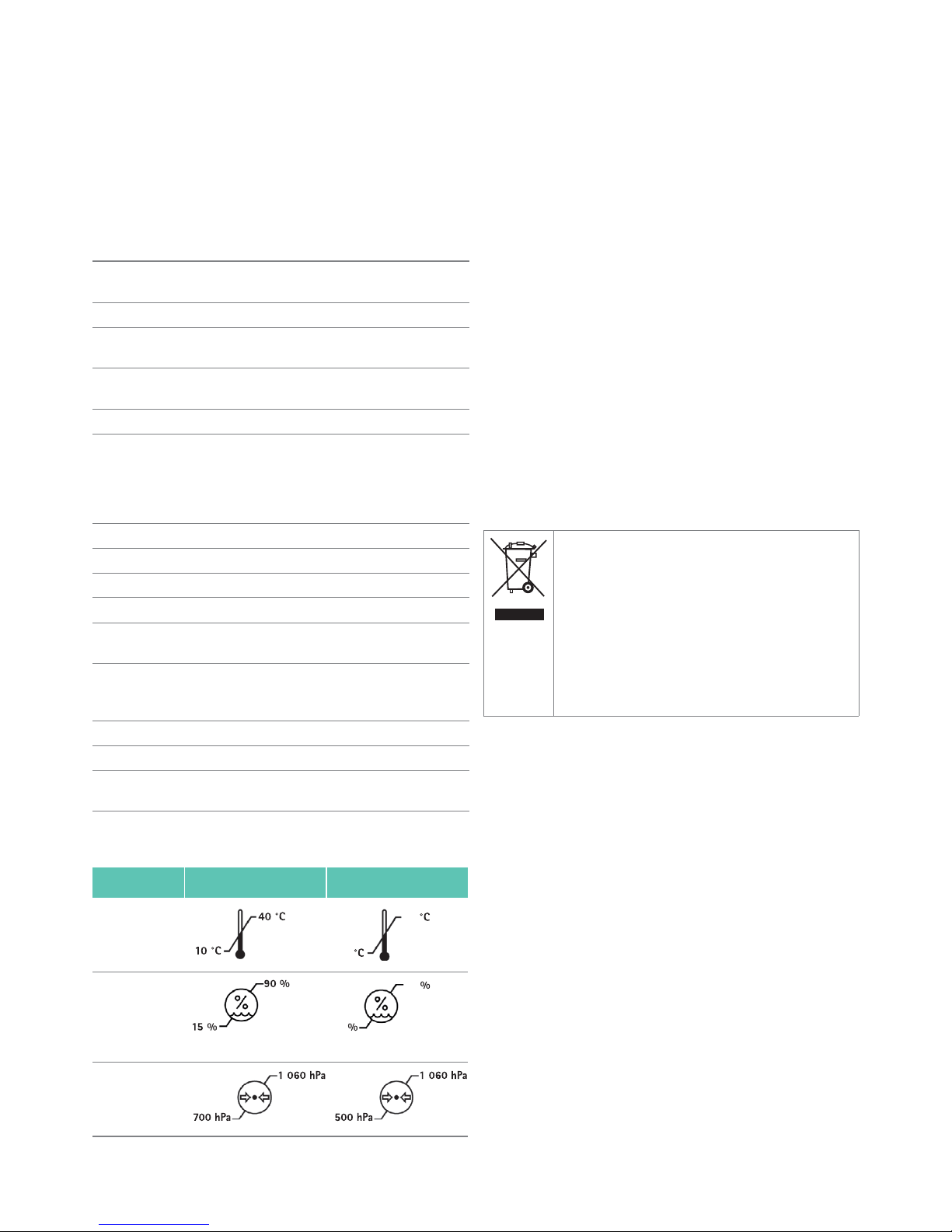
10.1 Ambient conditions
Note
The atmospheric pressure of 700 hPa corresponds to a maximum operating
altitude of 3 000 m.
Note
After transporting or storing at temperature outside the operating temperature range, leave the HF generator for one hour before use so that it can
reach room temperature.
11. Disposal
Note
The user institution is obliged to process the product before its disposal, see
Validated reprocessing procedure.
Ź Detailed information concerning the disposal of the product is avail-
able through your national B. Braun/Aesculap agency, see Technical
Service.
12. Distributor in the US/Contact in Canada for product information and complaints
Aesculap Inc.
3773 Corporate Parkway
Center Valley, PA, 18034,
USA
Mains voltage ranges
(Current intake)
100V~–240 V~ (6.7 A–2.8 A)
Frequency 50–60 Hz
Protection class (acc. to
IEC / DIN EN 60601-1)
I
Foot switch circuit ignition-safe acc. to IEC/DIN EN 60601,
approved for use in “medical environment”
Output power 2 x 150 W on 50 Ohm
Device protection
Time-Current characteristic
Breaking capacity
Construction
T8 AH/250 V
T (Time lag)
H (1 500 A)
5 mm x 20 mm
HF operating frequency 460 kHz ± 1 %, Quasi-Sinus
Operating mode Int 10 s/30 s
Weight 8.1 kg
Dimensions (L x W x H) 400 mm x 355 mm x 100 mm
Application part type acc.
to IEC/DIN 60601-1
CF
Recovery time of the defibrillation-protected output
0 seconds
CISPR11 Class A
EMC IEC/DIN EN 60601-1-2
Conforming to standard IEC/DIN EN 60601-1
IEC/DIN EN 60601-2-2
Operation Storage and transport
Temperature
Relative
humidity
non-condensing non-condensing
Atmospheric
pressure
-10-10
50
10
90
Adhere to national regulations when disposing of or recycling the product, its components and its packaging!
The recycling pass can be downloaded from the Extranet
as a PDF document under the respective article number.
(The recycling pass includes disassembling instructions for
the product, as well as information for proper disposal of
components harmful to the environment.)
Products carrying this symbol are subject to separate collection of electrical and electronic devices. Within the
European Union, disposal is taken care of by the manufacturer as a free-of-charge service.

20
Aesculap®
Lektrafuse HF-Generator GN200
Aesculap
®
Lektrafus e HF-Gen erator G N200
Legende
1 Signallampe HF-ON (umliegender Ring)
2 Taster Betriebsartenwahl (MODE) (Mitte)
3 Anschlussbuchse (Fußpedal)
4 Signallampe Regrasp
5 Anzeige
6 Signallampe Fehler
7 Signalring Instrument
8 Anschlussbuchse (Instrument)
9 Signallampe Netz-EIN
10 Anschluss (Potenzialausgleich)
11 Sicherungshalter (mit 2 Sicherungen)
12 Schalter Netz-AUS/EIN
13 Netzeingangsbuchse
14 Typenschild
15 Lüftungsschlitze
Symbole an Produkt und Verpackung
Vorsicht
Wichtige sicherheitsbezogene Angaben wie Warnhinweise und Vorsichtsmaßnahmen in Gebrauchsanweisung beachten.
Gebrauchsanweisung befolgen
Kennzeichnung von Elektro- und Elektronikgeräten
entsprechend Richtlinie 2002/96/EG (WEEE), siehe
Entsorgung
Fußpedal
Regrasp
Defibrillationsgeschütztes Anwendungsteil des Typs
CF
Potenzialausgleich
Sicherung
Nichtionisierende Strahlung
Wechselstrom
Chargenbezeichnung
Seriennummer
Bestellnummer
Herstelldatum
LOT
21
Inhaltsverzeichnis
1. Sichere Handhabung 21
1.1 Sichere Handhabung gemäß IEC-/VDE-Bestimmungen 22
2. Gerätebeschreibung 23
2.1 Lieferumfang 23
2.2 Zum Betrieb erforderliche Komponenten 23
2.3 Verwendungszweck 23
2.4 Funktionsweise 23
2.5 Signaltöne 24
2.6 Überwachungsfunktionen 24
2.7 Diagramme Ausgangsleistung 25
2.8 Maximale Ausgangsspitzenspannung (Up) 25
3. Vorbereiten und Aufstellen 25
3.1 Erstinbetriebnahme 25
4. Arbeiten mit dem Lektrafuse HF-Generator GN200 26
4.1 Bereitstellen 26
4.2 Funktionsprüfung 28
4.3 Bedienung 28
5. Validiertes Aufbereitungsverfahren 29
5.1 Allgemeine Sicherheitshinweise 29
5.2 Allgemeine Hinweise 29
5.3 Vorbereitung am Gebrauchsort 29
5.4 Vorbereitung vor der Reinigung 29
5.5 Reinigung/Desinfektion 30
5.6 Wischdesinfektion bei elektrischen Geräten ohne
Sterilisation 31
5.7 Kontrolle, Wartung und Prüfung 31
5.8 Lagerung und Transport 31
6. Instandhaltung 31
6.1 Sicherheitstechnische Kontrolle 31
7. Fehler erkennen und beheben 33
7.1 Regrasp-Fehler 33
7.2 Warnungen 34
7.3 Störungsmeldungen 34
7.4 Fehlermeldungen 35
7.5 Problembehebung 36
7.6 Fehlerbehebung durch den Anwender 36
7.7 Sicherungswechsel 36
8. Technischer Service 37
9. Zubehör/Ersatzteile 37
10. Technische Daten 37
10.1 Umgebungsbedingungen 38
11. Entsorgung 38
1. Sichere Handhabung
Hinweis
Diese Gebrauchsanweisung beschreibt nur Aufbau, Funktion und Bedienung des Lektrafuse Generators GN200 und ist nicht dazu geeignet, einen
Anfänger in die Hochfrequenz-Chirurgie einzuführen.
Ŷ Allgemeine Risiken eines chirurgischen Eingriffs sind in dieser
Gebrauchsanweisung nicht beschrieben.
Ŷ Der Operateur trägt die Verantwortung für die sachgemäße Durchfüh-
rung des operativen Eingriffs.
Ŷ Der Operateur muss sowohl theoretisch als auch praktisch die aner-
kannten Operationstechniken beherrschen.
Ź Produkt nur im Originalkarton transportieren.
Ź Vor der Anwendung des Produkts Funktionsfähigkeit und ordnungsge-
mäßen Zustand prüfen.
Ź „Hinweise zur elektromagnetischen Verträglichkeit (EMV)“ beachten,
siehe TA022130.
Ź Der Lektrafuse HF-Generator GN200 erfüllt die Anforderungen nach
CISPR 11 Klasse A.
Ź Um Schäden durch unsachgemäßen Aufbau oder Betrieb zu vermeiden
und die Gewährleistung und Haftung nicht zu gefährden:
– Produkt nur gemäß dieser Gebrauchsanweisung verwenden.
– Sicherheitsinformationen und Instandhaltungshinweise einhalten.
– Nur Aesculap-Produkte miteinander kombinieren.
– Anwendungshinweise gemäß Norm einhalten, siehe Sichere Hand-
habung gemäß IEC-/VDE-Bestimmungen.
Ź Zubehör regelmäßig prüfen: Insbesondere sollten Elektrodenkabel und
endoskopisches Zubehör auf mögliche Beschädigungen an der Isolation geprüft werden.
Ź Gebrauchsanweisung für den Anwender zugänglich aufbewahren.
Ź Gültige Normen einhalten.
GEFAHR
Verletzungsgefahr für den Patienten durch unsachgemäße Anwendung!
Ź Produkt und Zubehör nur von Personen betrei-
ben lassen, die die erforderliche Ausbildung,
Fachkenntnis oder Erfahrung haben.
WARNUNG
Verletzungsgefahr und Sachschäden bei Benutzung
des Produkts entgegen seinem Verwendungszweck!
Ź Produkt nur gemäß Verwendungszweck verwen-
den.
WARNUNG
Verletzungsgefahr und Sachschäden durch falsche
Handhabung des Produkts!
Der Lektrafuse HF-Generator bildet mit dem Zubehör ein System.
Ź Gebrauchsanweisung des Zubehörs des
Lektrafuse HF-Generators einhalten.
Ź Gebrauchsanweisung aller verwendeten Pro-
dukte einhalten.
22
Aesculap®
Lektrafuse HF-Generator GN200
1.1 Sichere Handhabung gemäß IEC-/VDE-Bestim-
mungen
Operationsumfeld
Ź Sicherstellen, dass das Gerät nicht in direkten Kontakt mit dem Patien-
ten bzw. in den Sterilbereich gelangt.
Ź Sicherstellen, dass der Anwender nicht zeitgleich in direkten Kontakt
mit dem Patienten und dem HF-Generator gelangt.
Sicherheit für den Patienten
GEFAHR
Lebensgefahr durch elektrischen Stromschlag!
Ź Produkt nicht öffnen.
Ź Produkt nur an ein Versorgungsnetz mit Schutz-
leiter anschließen.
WARNUNG
Verletzungsgefahr durch Zündung oder Explosion
von brennbaren Gasen! Beim bestimmungsgemäßen
Gebrauch des HF-Generators können Funken entstehen.
Ź Nicht im explosionsgefährdeten Bereich einset-
zen.
Ź Bei Operationen im Bereich von Kopf und Tho-
rax den Einsatz von zündfähigen Anästhetika
und verbrennungsfördernden Gasen (z. B. Lachgas, Sauerstoff) vermeiden oder diese Stoffe
absaugen.
Ź Wenn möglich, nicht brennbare Stoffe zur Rei-
nigung und Desinfektion verwenden.
Ź Wenn brennbare Reinigungs-, Desinfektions-
und Lösungsmittel verwendet werden: Sicherstellen, dass diese Stoffe vor dem Einsatz der
HF-Chirurgie verdunstet sind.
Ź Sicherstellen, dass sich keine brennbaren Flüs-
sigkeiten unter dem Patienten oder in Körperhöhlen (z. B. Vagina) sammeln. Bevor der HFGenerator eingesetzt wird, alle Flüssigkeiten
abwischen.
Ź Sicherstellen, dass keine endogenen Gase vor-
handen sind, die sich entzünden können.
Ź Sicherstellen, dass mit Sauerstoff getränkte
Materialien (z. B. Watte, Mull) so weit vom HFUmfeld entfernt sind, dass sie sich nicht entzünden können.
VORSICHT
Gefahr von Beeinträchtigungen anderer Geräte!
Beim bestimmungsgemäßen Gebrauch des HF-
Generators entstehen elektromagnetische Störfelder.
Ź Sicherstellen, dass keine elektronischen Geräte
im Umfeld des HF-Generators aufgestellt sind,
die durch elektromagnetische Störfelder beeinträchtigt werden können.
VORSICHT
Sichtbehinderung und/oder Nebenwirkungen durch
Dampf-/Rauchentwicklung bei HF-Chirurgie!
Ź Ggf. Rauchabsaugung verwenden.
GEFAHR
Lebensgefahr durch mangelnde Vorbereitung oder
Fehler am HF-Generator!
Ź Sicherstellen, dass der HF-Generator fehlerfrei
arbeitet.
Ź Sicherstellen, dass keine leitfähigen Flüssigkei-
ten (z. B. Blut, Fruchtwasser) in Fußpedal oder
Handschalter eingedrungen sind.
Ź Sicherstellen, dass im Fußpedal- oder Hand-
schalter-Kabel kein Kurzschluss vorliegt.
GEFAHR
Verbrennungsgefahr für den Patienten durch unbeabsichtigtes Aktivieren des HF-Generators!
Ź HF-Generator nach unbeabsichtigtem Aktivie-
ren sofort am Schalter Netz-AUS/EIN ausschalten.
Ź Fußpedal oder Handschalter immer mit beson-
ders hoher Aufmerksamkeit bedienen.
GEFAHR
Verletzungsgefahr für den Patienten durch unerwünschten Anstieg der HF-Ausgangsleistung bei
Versagen des HF-Generators!
Ź Gerät bei kleinsten Unregelmäßigkeiten nicht
mehr verwenden.
WARNUNG
Verletzungsgefahr für den Patienten/Anwender
durch defekte Netzzuleitung/nicht vorhandene
Schutzleiterverbindung!
Ź Netzzuleitung/Schutzleiterverbindungen prüfen.
WARNUNG
Gefahr von Verletzungen durch Muskelkontraktion
verursacht durch Stimulation der Nerven und Muskeln!
Ź An empfindlichen Strukturen mit besonderer
Aufmerksamkeit arbeiten.

23
Folgendes immer sicherstellen:
Ź Patienten so lagern, dass er keine Metallteile berührt, die geerdet sind
oder beträchtliche Kapazität gegen Erde haben (z. B. Operationstisch,
Halterungen). Bei Bedarf antistatische Tücher dazwischen legen.
Ź Sicherstellen, dass der Patient keine feuchten Tücher oder Unterlagen
berührt.
Ź Bereiche mit starker Schweißabsonderung und Haut-an-Haut-Berüh-
rungen am Körperstamm durch Zwischenlegen von antistatischen
Tüchern schützen.
Ź Urin über Katheter ableiten.
Ź Bei Operationen am Herzen HF-Generator über Potenzialausgleich
erden.
Ź Bei Patienten mit Herzschrittmachern oder anderen aktiven Implanta-
ten vor der Anwendung der HF-Chirurgie den entsprechenden Facharzt
konsultieren, um irreparable Schäden oder Fehlfunktionen am Schrittmacher oder dem Implantat zu vermeiden.
Ź Elektroden von physiologischen Überwachungsgeräten ohne Schutz-
widerstände oder HF-Drosseln möglichst weit entfernt von den HFElektroden anbringen.
Ź Keine Nadelelektroden für die Überwachung verwenden.
Ź Leitungen von Überwachungsgeräten so anbringen, dass sie nicht auf
der Haut liegen.
Ź Leitungen zu den HF-Elektroden möglichst kurz halten und so führen,
dass sie weder den Patienten noch andere Leitungen berühren.
Ź Bei unzureichender Leistung mit den gewohnten Einstellungen sicher-
stellen, dass:
– die Arbeitselektroden sauber sind,
– die Steckverbindungen korrekt sind.
Ź Aktive Elektrode nie auf oder neben dem Patienten ablegen.
Ź Zeitweise nicht benötigte aktive Elektroden so ablegen, dass sie den
Patienten nicht berühren.
Ź Bei Operationen, bei denen sich ein ständiger Kontakt der Elektroden
zum Patienten nicht vermeiden lässt (z. B. bei endoskopischen Operationen), HF-Generator bei unbeabsichtigtem Aktivieren der Elektrode
sofort am Schalter Netz-AUS/EIN 12 ausschalten.
Ź Heiße Elektrode nicht unmittelbar nach dem Schneiden oder Koagulie-
ren aus dem Körper entfernen.
Ź Während des Betriebs des Generators die Elektroden am Instrument
(auf der oberen oder unteren Seite) nicht berühren, da die Elektroden
sich erwärmen können und dies zu Verbrennungen oder Verletzungen
führen kann.
2. Gerätebeschreibung
2.1 Lieferumfang
2.2 Zum Betrieb erforderliche Komponenten
Ŷ Netzkabel
Ŷ Fußpedal (optional)
Ŷ Caiman Instrument
2.3 Verwendungszweck
Der Lektrafuse HF-Generator GN200 wird zur Gefäßversiegelung und
Gefäßtrennung in der offenen und minimal-invasiven Chirurgie eingesetzt. Die Instrumente können Gefäße bis einschließlich 7 mm versiegeln.
Der Lektrafuse HF-Generator ist nicht für den Einsatz bei Tubensterilisation/Tubenkoagulation zur Sterilisation geeignet.
Der Lektrafuse HF-Generator ist zur Anwendung am Herzen zugelassen
(Typ CF).
Der Lektrafuse HF-Generator ist für den Betrieb und die Lagerung in
geschlossenen Räumen bestimmt.
2.4 Funktionsweise
Der Lektrafuse HF-Generator GN200 arbeitet mikroprozessorgesteuert
und wandelt die Netzspannung in einen hochfrequenten Wechselstrom
für die bipolare Gefäßversiegelung um.
Der Versiegelungsprozess erfolgt über einen geschlossenen Regelkreis. Die
Versiegelung kann über die Taste am Instrument oder ein Fußpedal gestartet und gestoppt werden.
Der Lektrafuse HF-Generator GN200 besitzt zwei Betriebsarten:
Ŷ Standard-Modus: Voreingestellte Betriebsart
Ŷ Plus-Modus: Betriebsart mit erhöhter Energieabgabe
Bezeichnung Art.-Nr.
Hochfrequenz-Chirurgiegerät GN200
Gebrauchsanweisung TA022414
Hinweise zur elektromagnetischen
Verträglichkeit
TA022130
24
Aesculap®
Lektrafuse HF-Generator GN200
2.5 Signaltöne
2.6 Überwachungsfunktionen
Selbsttest
Beim Einschalten führt das Gerät einen Selbsttest durch, der Bedienelemente, Signalton, Mikroprozessor und Hardwarefunktion prüft. Während
dieser Phase erscheint in Anzeige 5 die Meldung “Performing Self-Test”.
Abb.1
Permanenter Test während des Betriebs
Während des Betriebs werden sicherheitsrelevante Funktionen und Signale zyklisch getestet. Wenn kritische Fehler erkannt werden, beendet der
HF-Generator die HF-Aktivierung. In Anzeige 5 wird die Fehlernummer
des entsprechenden Fehlers angezeigt und ein Signalton ausgegeben,
siehe Fehler erkennen und beheben.
Zustand/Status Signalton Bemerkung
System Fehlermeldung 3 Wiederholungen von: 1 langer Piepton, 3 KHz,
1 Piepton, 2 KHz
Nach jedem System-Fehler, wenn erkannt (F001,...)
REGRASP-Fehler 3 Wiederholungen von: 1 Piepton, 2 KHz,
1 Piepton, 3 KHz
Nach jedem Regrasp-Fehler, wenn erkannt
System Störungsmeldung 3 Pieptöne, 3 KHz Nach jeder Störungsmeldung, wenn erkannt (E001,..)
System Warnung 3 Pieptöne, 3 KHz Nach jeder Warnung, wenn erkannt
HF-Abgabe Start 2 Pieptöne 480 Hz Beim Start der HF-Abgabe
HF-Abgabe Aktiv Piepton, 480 Hz
Ŷ Im Standard-Modus: Wiederholung mit 1,8 Hz
Ŷ Im Plus-Modus: Wiederholung mit 2,8 Hz
Kontinuierlich während der HF-Abgabe
HF-Abgabe Ende 3 Pieptöne, 530 Hz Bei erfolgreicher Beendigung eines Versiegelungsprozesses
(keine Störungsmeldung oder Fehler)
Power Up Selbsttest 1 Piepton, 2 KHz Beim Selbsttest, um die Funktionalität des Signaltons zu über-
prüfen
25
2.7 Diagramme Ausgangsleistung
Darstellung der Ausgangsleistung als Funktion des Lastwiderstands.
Abb.2 Diagramm Ausgangsleistung Caiman 12 mm Seal & Cut Instru-
mentenfamilie
Abb.3 Diagramm Ausgangsleistung Caiman 5 mm Seal & Cut Instru-
mentenfamilie
2.8 Maximale Ausgangsspitzenspannung (Up)
Hinweis
Die folgenden Angaben ermöglichen dem Anwender zu beurteilen, ob der
HF-Generator GN200 für bestimmtes Zubehör (Qualität der Isolierung)
geeignet ist.
Maximale Ausgangsspitzenspannung (U
p
): 200 V
3. Vorbereiten und Aufstellen
Wenn die folgenden Vorschriften nicht beachtet werden, übernimmt
Aesculap insoweit keinerlei Verantwortung.
Ź Beim Aufstellen und Betrieb des Produkts einhalten:
– die nationalen Installations- und Betreiber-Vorschriften,
– die nationalen Vorschriften über Brand- und Explosionsschutz.
Hinweis
Die Sicherheit des Anwenders und des Patienten hängt u. a. von einer intakten Netzzuleitung, insbesondere von einer intakten Schutzleiterverbindung
ab. Defekte oder nicht vorhandene Schutzleiterverbindungen werden häufig nicht sofort erkannt.
Ź Gerät über den an der Geräterückwand montierten Anschluss für
Potenzialausgleichsleiter mit dem Potenzialausgleich des medizinisch
genutzten Raums verbinden.
Hinweis
Die Potenzialausgleichsleitung ist unter der Artikel-Nr. GK535 (4 m lang)
bzw. TA008205 (0,8 m lang) beim Hersteller erhältlich.
Ź Um eine ausreichende Belüftung und Kühlung des HF-Generators
sicherzustellen, rund um der HF-Generator mindestens 10 cm bis
15 cm Raum lassen.
3.1 Erstinbetriebnahme
WARNUNG
Verletzungsgefahr für den Patienten/Anwender
durch Verwendung von unzureichendem Zubehör
(Qualität der Isolierung)!
Ź Sicherstellen, dass die in den Begleitpapieren
des Zubehörs angegebene Bemessungszubehörspannung größer ist als die maximale Ausgangsspitzenspannung.
WARNUNG
Verletzungsgefahr und/oder Fehlfunktion des Produkts durch Fehlbedienung des medizinisch-elektrischen Systems!
Ź Gebrauchsanweisungen aller medizinischen
Geräte einhalten.

26
Aesculap®
Lektrafuse HF-Generator GN200
4. Arbeiten mit dem Lektrafuse HF-Gene-
rator GN200
4.1 Bereitstellen
Zubehör anschließen
Zubehörkombinationen, die nicht in der Gebrauchsanweisung erwähnt
sind, dürfen nur verwendet werden, wenn sie ausdrücklich für die vorgesehene Anwendung bestimmt sind. Leistungsmerkmale sowie Sicherheitsanforderungen dürfen nicht nachteilig beeinflusst werden.
Nur CAIMAN Instrumente können in Verbindung mit dem Lektrafuse HFGenerator GN200 eingesetzt werden, siehe Zubehör/Ersatzteile.
Spannungsversorgung anschließen
Die Netzspannung muss mit der Spannung übereinstimmen, die auf dem
Typschild des Geräts angegeben ist.
Das Gerät ist mit einem Weitbereichsnetzteil ausgerüstet, so dass die
Netzspannung zwischen 100 V und 240 V liegen kann, ohne dass der
Netzbereich umgeschaltet werden muss.
Ź Sicherstellen, dass das Gerät ausgeschaltet ist. Gegebenenfalls mit
Schalter Netz-AUS/EIN 12 ausschalten.
Ź Netzkabel an der Rückseite des Geräts in Netzeingangsbuchse 13 ein-
stecken.
Ź Netzstecker in die Steckdose der Hausinstallation stecken.
Gerät einschalten
Ź Gerät mit Schalter Netz-AUS/EIN 12 einschalten.
Die Signallampe Netz-EIN 9 leuchtet. Das Gerät führt einen Selbsttest
durch, siehe Permanenter Test während des Betriebs:
Ist kein Instrument angeschlossen, erscheint nach dem Selbsttest in
Anzeige 5 die Meldung “Attach Instrument”. Scheitert der Selbsttest,
wird eine Fehlermeldung auf Anzeige 5 ausgegeben.
Abb.4
Fußpedal anschließen
Der Anschluss des Fußpedals GN201 ist optional.
Am Fußpedalstecker und an der Anschlussbuchse Fußpedal 3 ist jeweils
ein Punkt als Markierung angezeichnet. Um den Stecker korrekt in die
Anschlussbuchse einstecken zu können, müssen diese Markierungen übereinander stehen.
Abb.5
GEFAHR
Verletzungsgefahr durch unzulässige Konfiguration
bei Verwendung weiterer Komponenten!
Ź Sicherstellen, dass bei allen verwendeten Kom-
ponenten die Klassifikation mit der Klassifikation des Anwendungsteils (z. B. Typ BF oder
Typ CF) des eingesetzten Geräts übereinstimmt.
GEFAHR
Lebensgefahr durch elektrischen Stromschlag!
Ź Produkt nur an ein Versorgungsnetz mit Schutz-
leiter anschließen.
Ź Gerät so aufstellen, dass das Ausschalten über
Schalter Netz-AUS/EIN problemlos möglich ist.
Ź Gerät so aufstellen, dass eine Trennung vom
Netzkabel problemlos möglich ist.
27
Ź Fußpedalstecker ausrichten und bis zum Einrasten in Anschlussbuchse
Fußpedal 3 einstecken.
Bei erfolgreicher Verbindung zwischen Gerät und Fußpedal erscheint in
Anzeige 5 für 3 Sekunden die Meldung "Footswitch attached".
Abb.6
Hinweis
Fußpedal während der HF-Abgabe nicht kontinuierlich betätigen. Die HFAbgabe wird gestartet und beendet durch einmaliges Drücken und Loslassen des Fußpedals.
Fußpedal entfernen
Ź Rast-Ring gegen Uhrzeigersinn drehen und gleichzeitig Anschlussste-
cker abziehen
In Anzeige 5 erscheint für 3 Sekunden die Meldung "Footswitch remo-
ved".
Abb.7
Instrument anschließen
Ausschließlich Instrumente der CAIMAN Seal & Cut Produktfamilie können in Verbindung mit dem Lektrafuse HF-Generator GN200 eingesetzt
werden.
Am Instrumentenstecker ist ein Pfeil und an der Anschlussbuchse 8 ein
Punkt als Markierung angezeichnet. Um den Stecker korrekt in die
Anschlussbuchse stecken zu können, müssen diese Markierungen übereinander stehen.
Abb.8
Ź Instrument in Anschlussbuchse 8 stecken.
Der grüne Signalring 7 um den Instrumentenanschluss leuchtet auf. In
Anzeige 5 erscheint die Meldung "Ready to Seal".
Abb.9
28
Aesculap®
Lektrafuse HF-Generator GN200
Betriebsart wählen
Der Lektrafuse HF-Generator besitzt zwei Betriebsarten für den Versiegelungsprozess. Die gewählte Betriebsart bleibt bis zum Ausschalten des HFGenerators erhalten. Die Betriebsart kann während des Eingriffs geändert
werden.
Ź Betriebsart wechseln: Taster Betriebsartenwahl (MODE) 2 betätigen.
Ŷ Standard-Modus: Voreingestellte Betriebsart
Ŷ Plus-Modus: Betriebsart mit erhöhter Energieabgabe
Die eingestellte Betriebsart ist unabhängig vom angeschlossenen Instrument. Das Wechseln oder Wiederverbinden des Instruments ändert nicht
die eingestellte Betriebsart.
Die aktive Betriebsart ist im Display folgendermaßen gekennzeichnet:
Ŷ Rahmen
Ŷ Fette Schrift
Abb.10
Abb.11
Hinweis
Bei einem Regrasp-Fehler wird die aktive Betriebsart nicht angezeigt. Die
aktive Betriebsart kann durch Betätigen des Tasters Betriebsartenwahl
(MODE) 2 angezeigt werden.
Hinweis
Der Plus-Modus kann durch die höhere Frequenz des Pieptons während der
HF-Abgabe vom Standard-Modus unterschieden werden.
Außerbetriebnahme
Ź Gerät mit Schalter Netz-AUS/EIN 12 ausschalten.
Alle Pole des Geräts werden vom Versorgungsnetz getrennt.
Ź Netzkabel abziehen.
Das Gerät ist vollständig vom Versorgungsnetz getrennt.
4.2 Funktionsprüfung
Korrekte Funktion des Geräts vor jedem Einsatz prüfen:
Ź Sicherstellen, dass das Zubehör keine sichtbaren Schäden hat.
Ź Gerät vorbereiten und aufstellen, siehe Vorbereiten und Aufstellen.
Ź Funktion folgender Elemente in der vorgegebenen Reihenfolge prüfen:
–Schalter Netz-AUS/EIN12 einschalten, Signallampe Netz-Ein 9
leuchtet
– Automatischer Selbsttest nach jedem Einschalten: kurzes akusti-
sches Signal, alle Anzeige-Elemente leuchten kurz auf
– Betriebsartenwahl, siehe Betriebsart wählen
– Fußpedal, siehe Fußpedal anschließen
– Instrument, siehe Instrument anschließen
– Aktivierung mit Taster an Instrument und Fußpedal
–Schalter Netz-AUS/EIN12 ausschalten
4.3 Bedienung
Ź Start des Versiegelungsprozesses (HF-Abgabe) durch einmaliges Drü-
cken des Tasters am Instrument oder des Fußpedals.
Nach Beendigung des Versiegelungsprozesses wird die HF-Abgabe
automatisch gestoppt.
Während des Versiegelungsprozesses erscheint in Anzeige 5 die Mel-
dung "Sealing in Progress".
Abb.12
Gerät ein-/ausschalten
Ź Gerät mit Schalter Netz-AUS/EIN 12 einschalten/ausschalten.
Betriebsart
Der Lektrafuse HF-Generator GN200 erkennt automatisch das angeschlossene Instrument. Interne Geräteeinstellungen werden geladen. Der Nutzer
kann zwischen zwei Betriebsarten wählen.
WARNUNG
Verletzungsgefahr und/oder Fehlfunktion!
Ź Vor jedem Gebrauch Funktionsprüfung durch-
führen.
WARNUNG
Verletzungsgefahr durch Verwendung des Produkts
außerhalb des Sichtbereichs!
Ź Produkt nur unter visueller Kontrolle anwenden.
 Loading...