

Page 1

Workshop Manual
NAVIGATOR
Copyright by
MVAGUSTA MOTORCYCLES S.p.A.
Via G. Macchi , 144 (Schiranna)
21100 VARESE - ITALY
1st Edition
Printed in Italy
Print no. - 8A0095860
1
Page 2

Introduction
This publication is intended for CAGIVA Workshops and is designed to help authorized
personnel in service and repair operations. Familiarity with the specifications provided
herein is a key factor in ensuring effective training of operators.
To make the manual easy to understand, the different paragraphs are identified by
icons that point out the subjects being dealt with.
Notes having special meanings are marked with the following symbols:
Accident-prevention rules for the operator and other people working close by.
There is a possibility that the vehicle and/or its components may be damaged.
Further information on the operation being performed.
Tips
To avoid problems and obtain the best possible results, CAGIVA recommends observ-
ing the following general rules:
- Before carrying out any repairs, evaluate the customer’s report of the vehicle’s malfunction and ask any questions that may help clarify the nature of the problem.
- Clearly identify the causes of the malfunction. This manual provides the fundamentals of troubleshooting, which the operator will complete with his personal experience
and the participation in the periodic training courses organized by CAGIVA.
- Make a rational plan of the repair so as to avoid wasting time in collecting spares,
preparing tools, etc.
- Only perform the operations that are required to reach the part to be repaired. Helpful
guidelines are provided in the disassembling and removing procedures described in
this manual.
General repairing rules
1 Always replace gaskets, sealing rings and cotter pins with new ones.
2 When loosening or tightening nuts or screws, always begin with the largest, or with
the one at the centre. Tighten with the prescribed torques using a crosswise pattern.
3 Always mark the parts and positions that might be exchanged when reassembling.
4 Use genuine CAGIVA spares, and lubricants of the recommended brands.
5 Use special tools as specified.
6 Consult the Technical Circulars, as they may contain updated information on adjust-
ing and service procedures.
2
Page 3
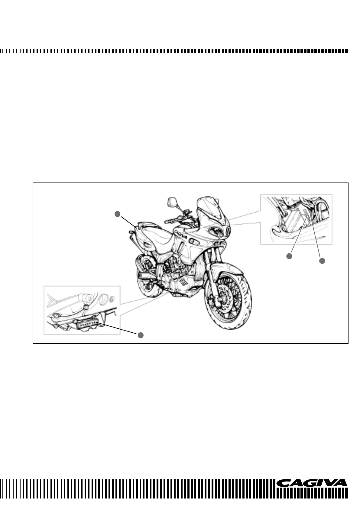
IDENTIFICATION DATA
The vehicle is identified by the following:
- Motorcycle serial number (1) on the right side of the head tube.
- Engine serial number (2) on the lower part of the right-hand crankcase half.
- Colour code on plate (3) inside the glove compartment under the saddle.
- Homologation data on the plate applied to the frame lower tube, next to the steering
head tube.
When ordering spares, always mention the motorcycle and engine serial numbers and
the colour code.
3
1
2
4
3
Page 4

Contents
Section Page
General information..................................................................... A 5
Maintenance............................................................................................B9
Injection - Air intake system ........................................................ C 45
Engine ......................................................................................... D 119
Suspensions and wheels ............................................................ E 299
Brakes ......................................................................................................F 324
Electrical equipment.................................................................... G 338
Engine cooling............................................................................. H 376
Specific tooling ............................................................................ I 390
Tightening torques....................................................................... L 394
Index .........................................................................................................M 400
4
Page 5

GENERAL INFORMATION
Section
A
A.1
Page 6

GENERAL INFORMATION
Dimensions and weight .......................................................... A-3
Engine unit ............................................................................. A-3
Transmission unit ................................................................... A-3
Frame..................................................................................... A-4
Front suspension.................................................................... A-4
Rear suspension .................................................................... A-4
Wheels and brakes ................................................................ A4
Electrical system .................................................................... A-4
Instrument panel .................................................................... A-4
Fuel/oil/coolant/fork oil capacity ............................................. A-4
A.2
Page 7
GENERAL INFORMATION
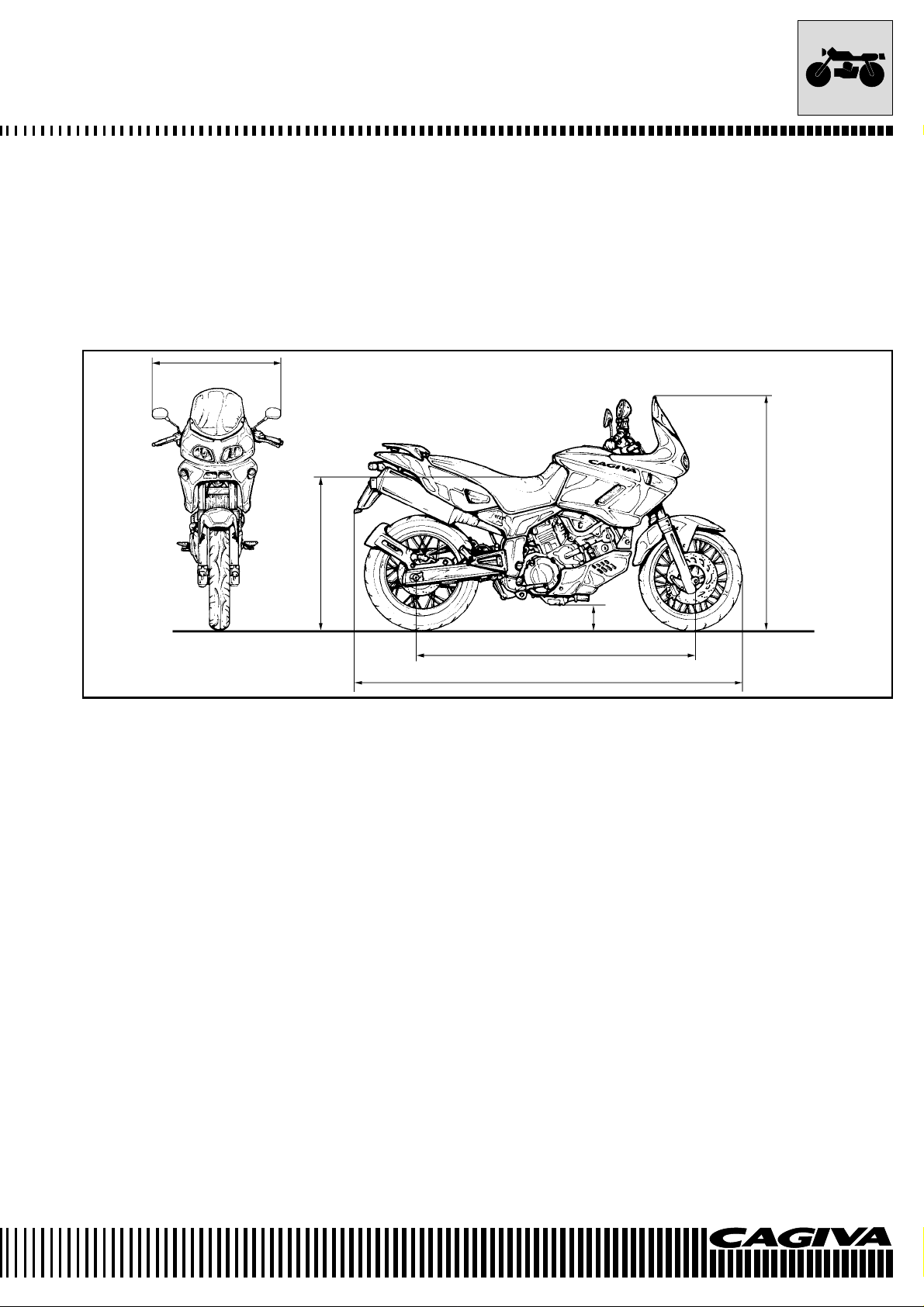
DIMENSIONS AND WEIGHTS
NAVIGATOR
Overall length .......................................................................... 2168 mm
Overall width ........................................................................... 790 mm
Overall height .......................................................................... 1290 mm
Wheelbase .............................................................................. 1530 mm
Ground clearance.................................................................... 180 mm
Seat height .............................................................................. 850 mm
Dry weight ............................................................................... 222 kg
790
850
1290
180
1530
2168
ENGINE UNIT
Type ............................................................................................ Liquid cooled, DOHC, TSCC four stroke
Number of cylinders .................................................................... 2
Bore............................................................................................. 98,0 mm
Stroke.......................................................................................... 66 mm
Displacement .............................................................................. 996 cm
Compression ratio ....................................................................... 11.3 : 1
Fuel feed system......................................................................... Injection
Air filter ........................................................................................ Non woven synthetic material
Starter system ............................................................................. Electric
Lubrication system ...................................................................... Wet sump
3
TRANSMISSION UNIT
Clutch .......................................................................................... Wet multi-plate type
Gearbox ...................................................................................... 6 speed constant mesh
Gear change ............................................................................... 1 down, 5 up
Primary reduction ........................................................................ 1.838 (57/31)
Final reduction............................................................................. 2.562 (41/16)
Gear ratios, 1a ............................................................................ 2.666 (32/12)
2a .................................................................. 1.933 (29/15)
3a .................................................................. 1.500 (27/18)
4a .................................................................. 1.227 (27/22)
5a .................................................................. 1.086 (25/23)
6a .................................................................. 1.000 (24/24)
Transmission chain ..................................................................... 5/8” x 5.16”
A.3
Page 8

GENERAL INFORMATION
FRAME
Type ........................................................................................... Rectangular and square box section tubular framework
in highly resistant steel with box-type strengthening
supports at the fork fulcrum attachment.
FRONT SUSPENSION
Type ........................................................................................... Conventional advanced pivot hydraulic telescopic fork
with 45 mm diameter tubes. Telescopic movement 150 mm.
Steering angle ............................................................................ 32° (left and right)
Steering head angle ................................................................... 25°
Trail ............................................................................................ 110 mm
REAR SUSPENSION
Type ............................................................................................Single hydraulic shock absorber progressively damped
with external pre-load adjustment of the spring and
extension of the hydraulic braking effect. Wheel travel 160 mm.
WHEELS AND BRAKES
Front brake................................................................................. Twin disc
Rear brake ................................................................................. Single disc
Front tyre.................................................................................... Metzeler ME Z4 C – 110/80 – 18”
Rear tyre .................................................................................... Metzeler ME Z4 – 150/70 – 17”
ELECTRICAL SYSTEM
Transistorised electronic ignition
Ignition phase............................................................................. 3° before T.D.C. at 1300 rpm
Spark plugs ................................................................................ NGK CR8EK or DENSO U24ETR
Battery........................................................................................ 12v 10Ah
Generator ................................................................................... Three phase AC generator
Fuses ......................................................................................... 30/30/15/15/15/10/10A
Headlight unit ............................................................................. Main beam: condenser halogen bulb H1 12v-55w
Dipped beam: polyellipsoidal bulb H3 12v-55w
Sidelight ..................................................................................... 12v 5w
Direction indicators..................................................................... 12v 10w
Number plate light ...................................................................... 12v 5w
Brake/tail light............................................................................. 12v 21/5w
INSTRUMENT PANEL
Instrument bulb .......................................................................... 12V 1.2W
Warning lights ............................................................................ 12V 2W
FUEL/OIL/COOLANT/FORK OIL CAPACITY
Fuel tank ..................................................................................... 20 L
Engine oil: oil change .................................................................. 3100 ml
oil change with filter ................................................ 3300 ml
overhaul .................................................................. 3600 ml
Engine coolant ............................................................................ 2000 ml
Fork oil (each tube) ..................................................................... 680 ml
A.4
Page 9

MAINTENANCE
Section
B
B.1
Page 10

MAINTENANCE
Maintenance and tuning......................................................... B-4
Compression check................................................................ B-23
Oil pressure check ................................................................. B-24
Technical data ........................................................................ B-25
B.2
Page 11
MAINTENANCE
Check ■ Substitution ● First Every Every Every Every Every
1000 km 1000 km 6000 km 12000 km 20000 km 24000 km
Engine oil Check level ■
Engine oil Substitute ●●
Engine oil filter Substitute ●●
Coolant Check level ■■
Coolant Substitute
Valve tappet clearance adjustment Check/adjust ■
Timing chain tension Check/adjust ■■
Synchronisation butterfly valves Check/adjust ■
Spark plugs Check/substitute ■■●
Fuel filter Substitute ●
Air filter Check/substitute ■●
Fuel feed system Check ■
Brake fluid Check level ■■
Brake fluid Substitute
Brake disc pads Check ■
Brake discs Check ■
Braking system Check ■
Braking system Bleed air Every 20000 km
Every 2 years
Every 2 years
/every 2 years
Accelerator control Check/adjust ■■
Clutch control Check ■■
Steering Check bearing play ■■
Fork Substitute oil
Secondary transm
Crown and pinion, chain Check/substitute ■
Tyres Check pressure/substitute ■■
Screws and bolts Check for tightness ■■
Fuel tubing Substitute
Clutch cover screws Check for tightness ■
Rear wheel bearings Check ■
ission chain
Check tension/lubrication ■■
Every 2 years
Every 4 years
●
B.3
Page 12
MAINTENANCE
MAINTENANCE AND TUNING
This section describes the servicing procedures for each part of periodical maintenance.
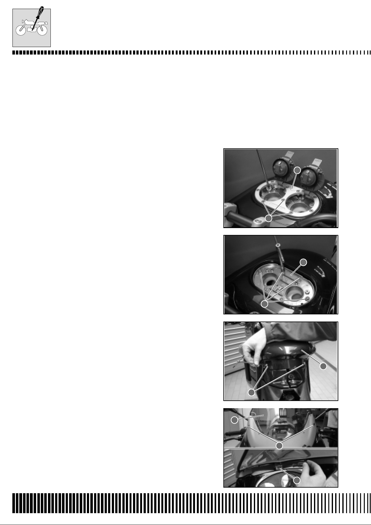
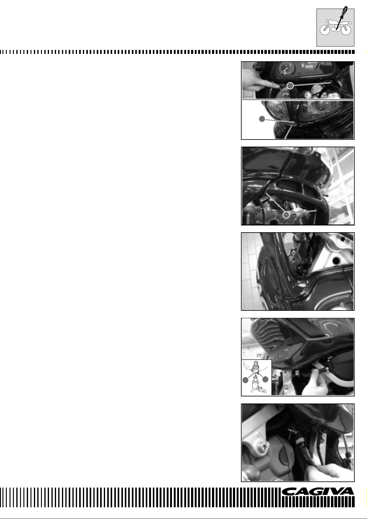
FUEL TANK REMOVAL
To complete this operation it is necessary to previously remove the
seat.
• Remove the complete fuel tap assembly by unscrewing the three
screws 1 indicated in the figure.
• Extract the flange 2 of the petrol covers.
2
• Remove the six screws 3 using an 8mm spanner.
• Extract the plate 4 paying attention to the two washers underneath.
• Remove the tank cover 5 by unscrewing the two screws 6.
• Remove the windshield 7 by unscrewing the three screws 8 shown
in the figure.
1
4
3
5
6
B.4
7
8
8
Page 13
MAINTENANCE
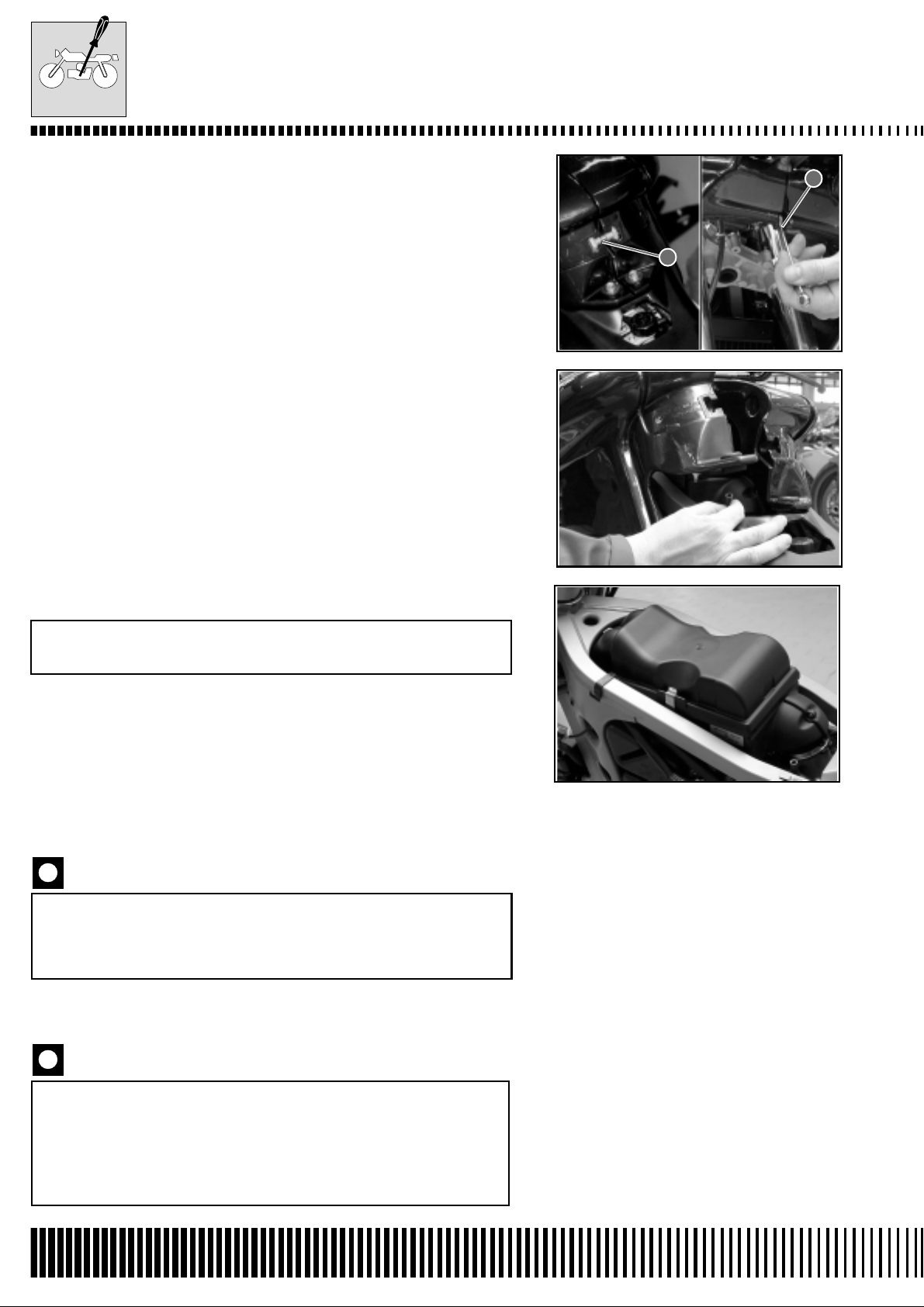
• Remove the fairing by unscrewing the five screws 1. There is one
front screw and four screws highlighted in the figure.
• Remove the front protection by unscrewing the two lower screws
2, as shown in the figure.
1
1
• Disconnect the indicator connectors. One is indicated in the figure
and the other is on the opposite side of the machine.
• Disconnect the fuel tubes from the left fuel tank. The fuel tubes
are attached to the fuel tank by rapid attachments and their removal automatically blocks the exit of fuel. It is necessary to push
the lever 3 and slide out the elbow union 4 to disassemble it. Before effecting reassembly , check that the small pin 4 is completely
extended. If it is not in position, push on the lever 3 to bring it into
position.
2
3
4
• Disconnect the reserve fuel sensor connector attached to the right
fuel tank.
B.5
Page 14
MAINTENANCE
• Slacken and remove the two tank union clamps 1. One is situated
at the front of the vehicle and the other at the back of the tank.
• Finally, remove the two fixing screws 2. Disconnect the overflow
tube from the left fuel tank.
1
1
AIR FILTER
Check every 6000 km (or 6 months)
Substitute every 12000 km (or 12 months).
• It is necessary to remove the fuel tanks before removing the air
filter.
• Carefully eliminate dust and dirt from the filter element by using
compressed air.
The compressed air must be blown from the exterior of
the filter element. If compressed air is used internally, the
dust and dirt will be pushed into the pores of the filter
thereby reducing the flow of air to the same element.
• To assemble a clean or new filter element, carry out the operation
of disassembly in the reverse order.
Should the motorcycle be used frequently on dusty roads,
the filter element must be cleaned more frequently. The
use of the engine without a filter or with a broken filter
element will certainly shorten the life of the engine. Check
that the air filter is always in good condition. The long life
of the engine depends a lot on this component!
B.6
Page 15
MAINTENANCE
SPARK PLUGS
Check every 6000 km (or 6 months)
Substitute every 12000 km (or 12 months)
After the first 1000 km it is necessary to remove the spark plugs,
clean them and check the distance between the electrodes (0.6÷0.7
mm).
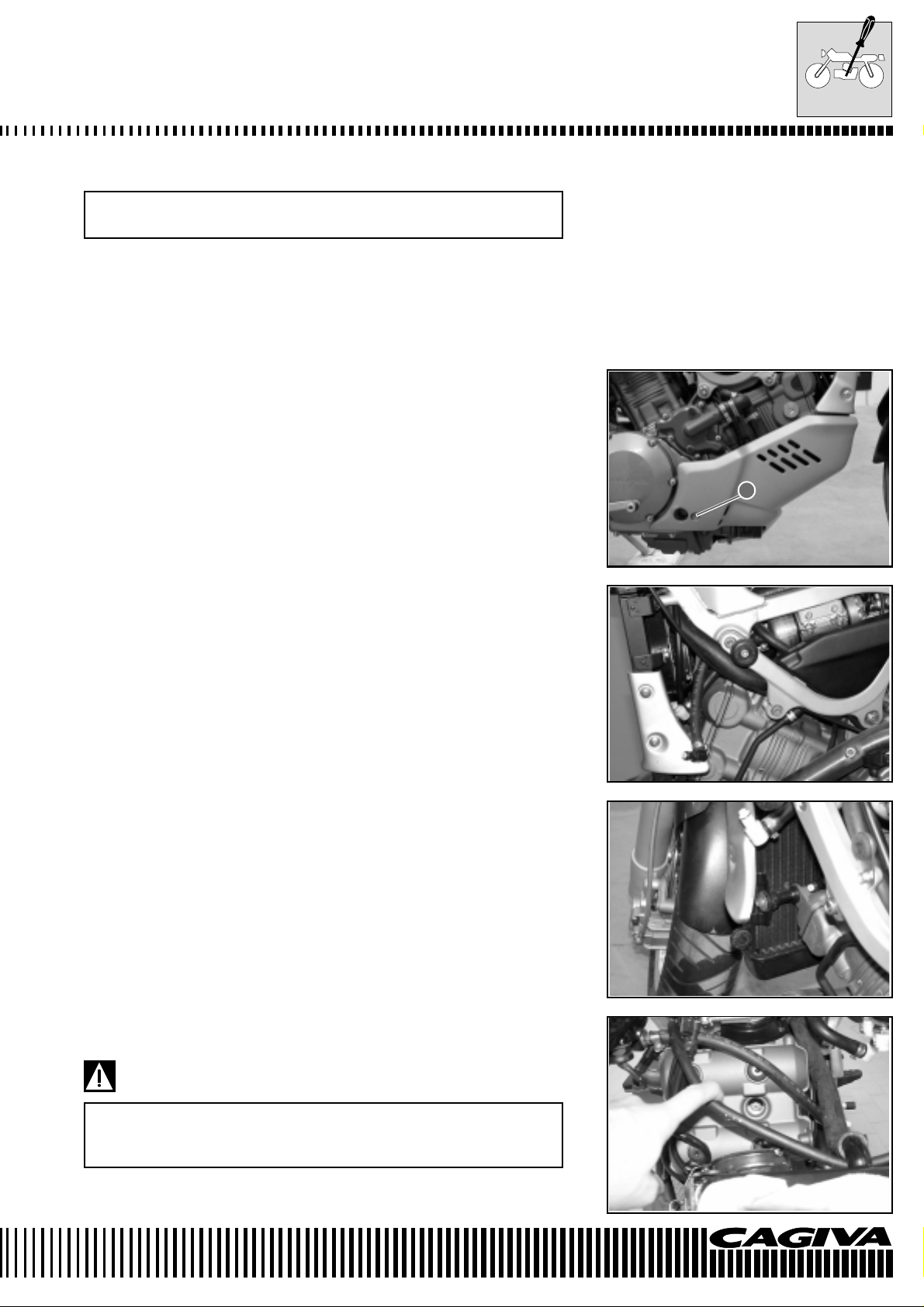
REMOVAL OF SPARK PLUG N° 1 (FRONT)
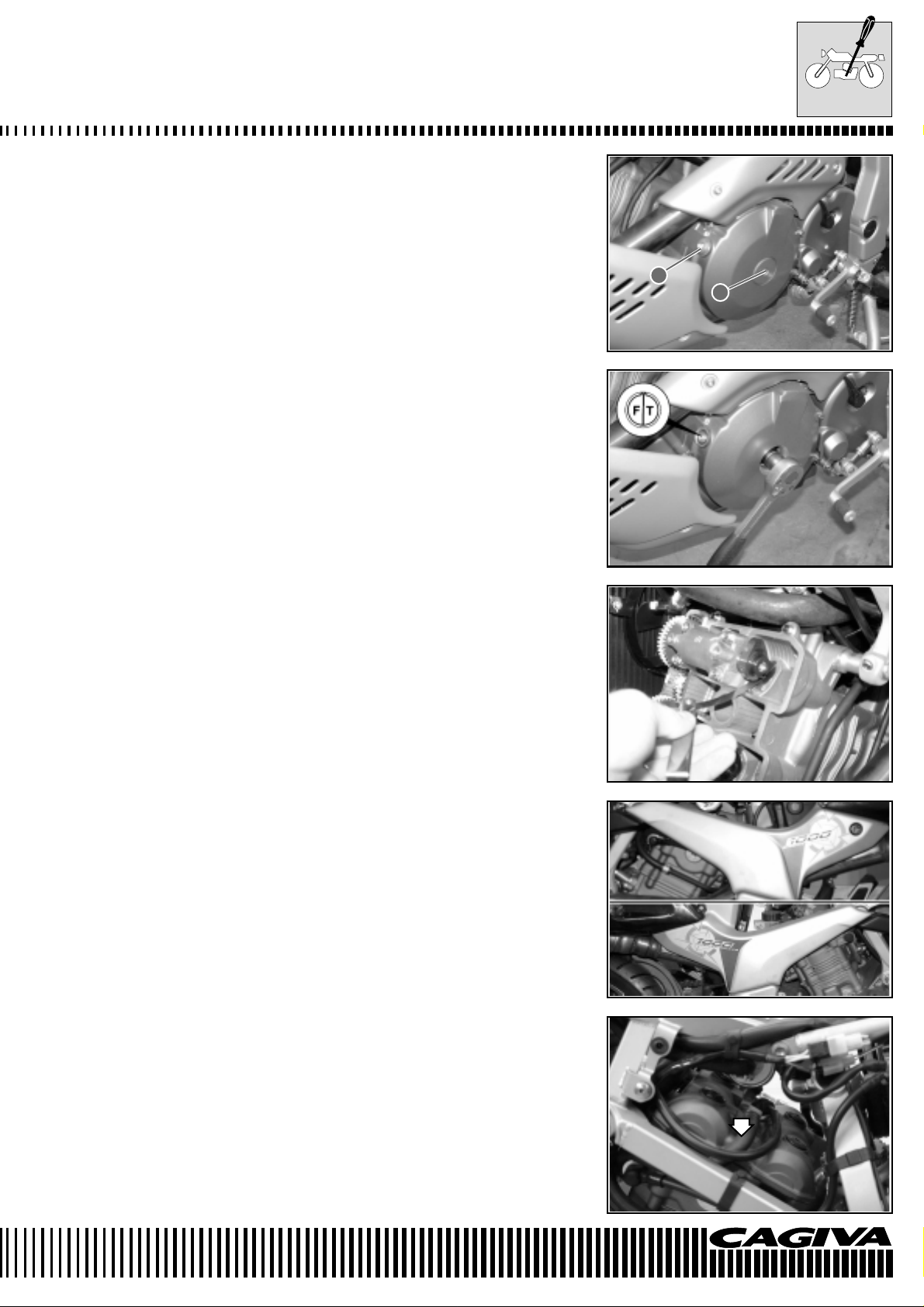
• Remove the sump guard by unscrewing the two screws 1. One
screw is indicated in the figure whilst the other screw is on the
other side.
1
• Disconnect the fuel tubes.
• Remove the left side protection of the radiator.
• Remove the lower radiator fixing and its spacer. Unhook the radiator from its mountings.
• Push the radiator down so that there is access to the forward spark
plug.
• Remove the spark plug insulated cap.
• Unscrew the spark plug as shown in the figure.
During this operation, pay attention to the front mudguard.
Place a piece of cloth between the radiator and the mudguard as shown in the figure.
B.7
Page 16
MAINTENANCE
Be careful to not damage the finning of the radiator.
The radiator and engine can provocate serious burns when
they are hot. Wait until the radiator and the engine are cool
enough to be touched before carrying out this operation.
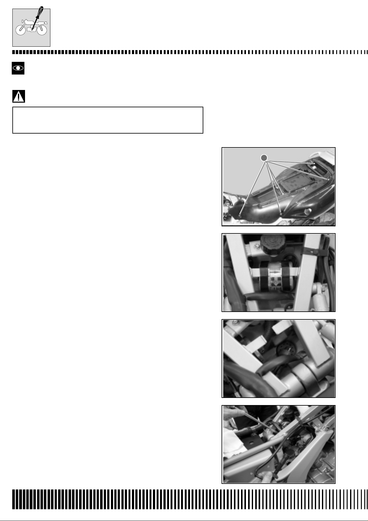
REMOVAL OF SPARK PLUG N° 2 (REAR)
• Remove the seat.
• Remove the seat compartment by unscrewing the eight screws 1.
Six of theses screws are shown in the figure.
1
• Unhook the rubber mountings of the fuel filter.
• Remove the spark plug insulated cap.
• Remove the spark plug.
B.8
Page 17
MAINTENANCE
HEAT GRADE CODE
• Check the heat grade code of the spark plug.
NGK CR8EK
DENSO U24ETR
The type “R” spark plug has a resistor on the central electrode to
avoid radio disturbance.
CARBON DEPOSITS
• Check the spark plugs for carbon deposits. If there are deposits,
use the appropriate machine or a pointed tool to eliminate them.
Take care in using the pointed tool.
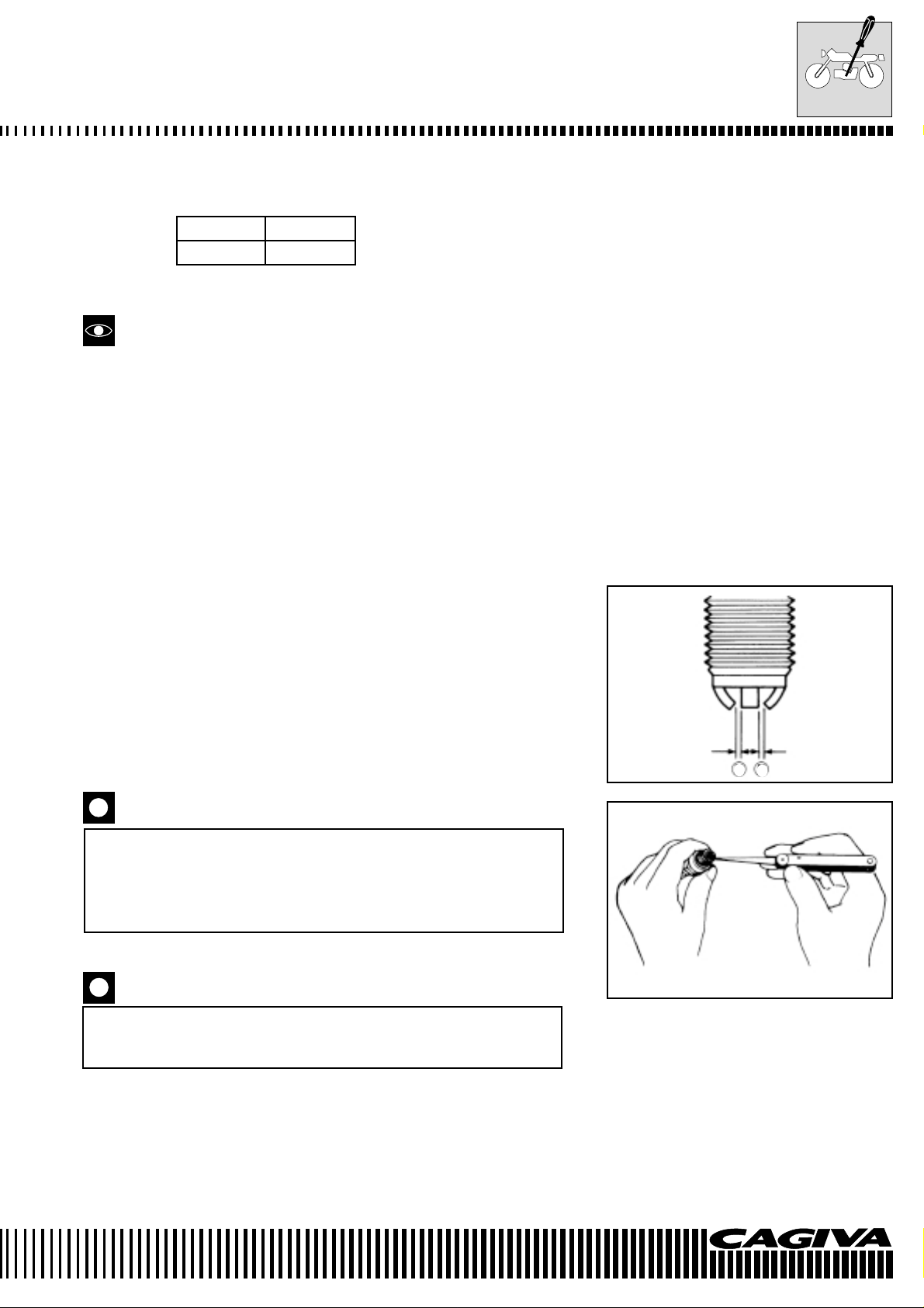
THE GAP BETWEEN THE SPARK PLUG ELECTRODES
• Measure the gap between the spark plug electrodes using feeler
blades. Adjust the gap if it is not correct, using the following information:
Specific tool: 800096651: Feeler gauge
800096872: Feeler gauge
Standard
Normal gap between the electrodes of the spark plug A: 0,6÷0,7 mm
THE CONDITION OF THE ELECTRODES
• Controllare se gli elettrodi sono usurati o bruciati. Se essi fossero
estremamente usurati o bruciati,sostituire la candela.
Sostituire la candela anche in caso di rottura dell’isolante o danneggiamento della filettatura.
When a spark plug substitution is made, check the pitch
size and the length of the thread. If the threading is too
short, carbon residues will be deposited on the threading
of the cylinder head thereby possibly causing damage to
the engine.
REPLACING THE SPARK PLUG AND INSULATED CAP
Carefully screw the spark plug into place by hand before
tightening with a plug spanner. This is to avoid damage to
the aluminium threading.
• Manually screw in the spark plugs into the cylinder heads and
tighten them to the specific torque.
A A
Torque pressure
Spark plug: 11 N·m (1,1 kg-m)
B.9
Page 18
MAINTENANCE
When the front and rear spark plug insulated caps are pushed on,
turn the triangular signs on the insulated caps A towards the exhaust side of the cylinders.
VALVE TAPPET CLEARANCE ADJUSTMENT
Check every 24000 km (or every two years)
• Remove the seat.
FRONT CYLINDER
• Remove the spark plug as described in page B-7.
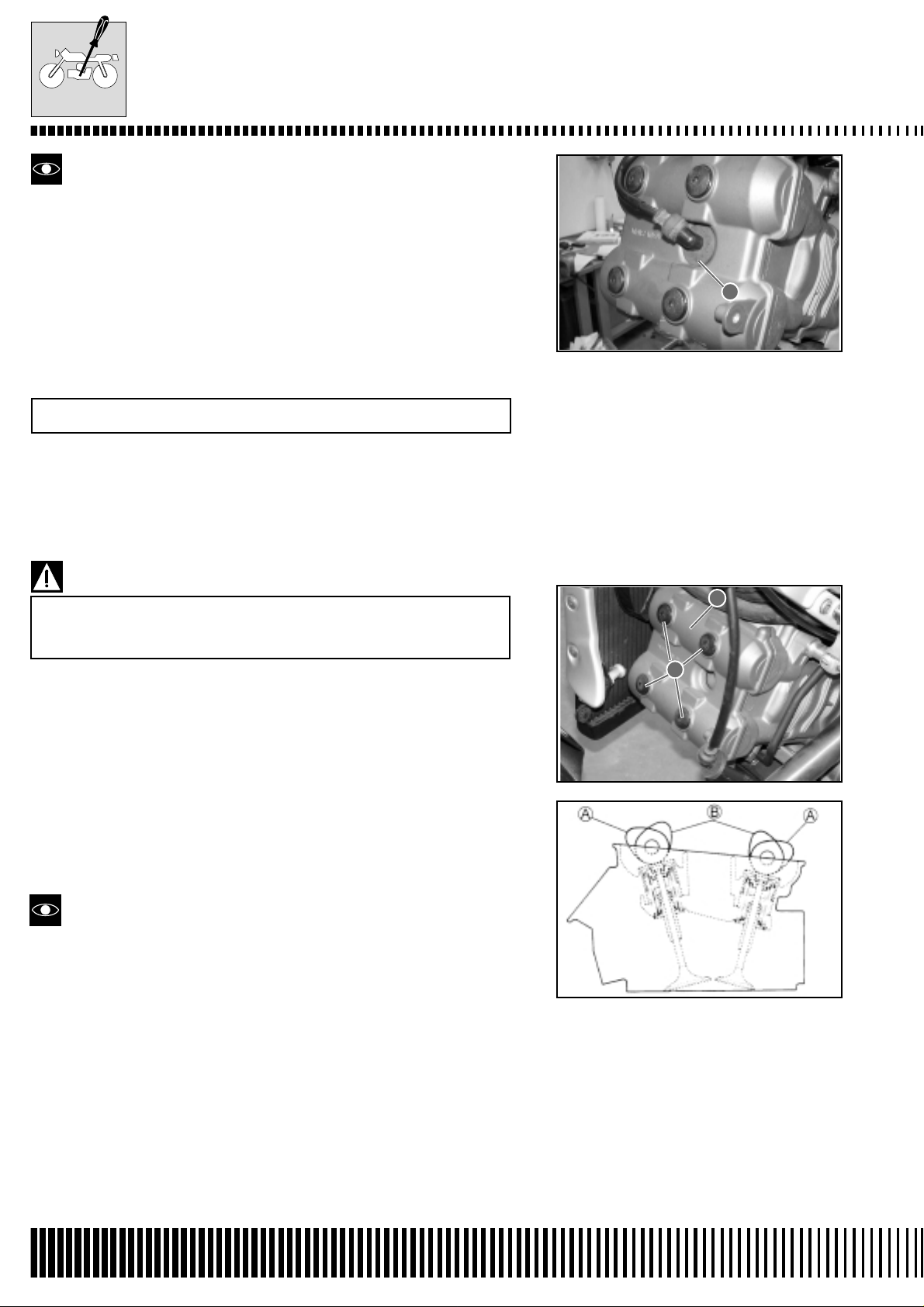
• Remove the front cylinder head valve cover 1 by unscrewing the
four screws 2 shown in the figure.
A
When removing the valve cover, be careful that the locating pins or the gasket do not fall to the ground or inside
the cover opening.
The valve tappet clearances vary between the inlet and the exhaust
valves.
The valve tappet clearance adjustment must be checked and adjusted:
1) During periodical maintenance.
2) When tappet maintenance is carried out.
3) When the camshafts are removed for maintenance.
Valve tappet clearances (cold):
Inlet : 0.10 - 0.20 mm
Exhaust : 0.20 - 0.30 mm
* Valve tappet clearances must be checked when the piston is in
the top dead centre (T.D.C.) position of the compression cycle.
* The inlet and exhaust cams of the front cylinder in position A indi-
cate that the front piston is in the top dead centre (T .D.C.) position
of the compression cycle.
* The inlet and exhaust cams of the rear cylinder in position B indi-
cate that the rear piston is in the top dead centre (T .D.C.) position
of the compression cycle.
* Specified valve tappet clearances are with a COLD engine.
* Use a 17 mm spanner to turn the camshaft when checking the
valve tappet clearances. The camshaft must be turned in the direction of normal engine operation. Both spark plugs must be removed.
1
2
IN.
EX.
B.10
Page 19
MAINTENANCE
• Remove the plug of the generator cover 1 and the timing cover
inspection plug 2.
• Turn the engine camshaft to bring the piston of the N° 1 cylinder
(front) to the top dead centre (T.D.C.) position of the compression
cycle. Align the “F/T” line on the generator rotor with the timing
inspection hole line and bring the camshafts to the indicated position in page B- 10.)
2
1
• To check the valve tappet clearances of the N° 1 cylinder (front),
insert a feeler gauge between the valve stem and the cam. If the
clearance is not correct, adjust it within the specified range.
REAR CYLINDER
• Remove the seat, the seat compartment and the spark plug as
described in page B-8.
• Remove the left and right hand side panels by unscrewing the two
screws.
• Disconnect the oil vapour tube from the left hand side of the machine.
B.11
Page 20
MAINTENANCE
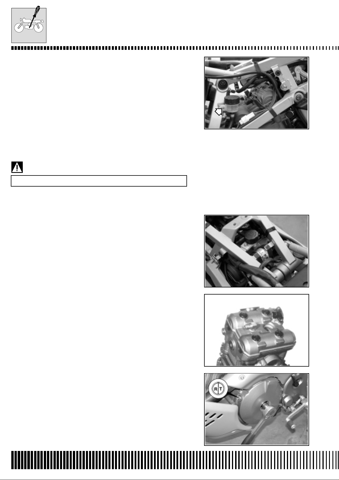
• Unhook the rear brake fluid chamber by unscrewing the screw
shown in the figure.
• Disconnect the electrical connector of the camshaft position sensor.
• Remove the sensor by unscrewing the two relative screws.
• Disassemble the fuel filter from its supports and disconnect it from
the fuel tubes, taking care to not spill any fuel.
Place a cloth underneath the fuel filter.
• Disassemble the expansion tank cover assembly.
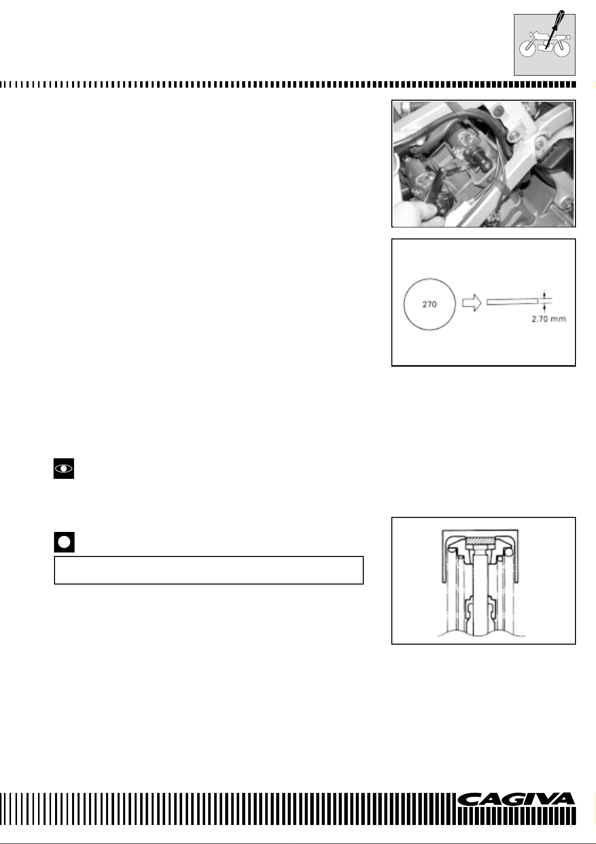
• Remove the rear cylinder head valve cover by unscrewing the
four relative screws shown in the figure.
• Rotate the crankshaft 270° (3/4 of a turn) to bring the piston of N°
2 cylinder (rear) to T.D.C. of the compression cycle. Align the “R/
T” line on the rotor of the generator with the counter-line of the
timing synchronisation inspection hole and bring the camshafts in
the position indicated at page B-7.
B.12
Page 21
MAINTENANCE
• Check the valve tappet clearance of the N° 2 cylinder (rear) using
the same procedure used for the N° 1 cylinder (front) and adjust
as necessary.
VALVE TAPPET CLEARANCE ADJUSTMENT
The valve tappet clearance adjustment is regulated by the substitution of the valve stem pad with another that is thicker or thinner.
• After having removed the cylinder head valve covers, remove the
intake and exhaust camshafts as described in chapter D.
• Remove the cup and pad with the fingers or a magnet.
• Check the number on the pad. This number indicates the thickness of the pad as illustrated.
• Choose a substitute pad that allows a valve tappet clearance within
the prescribed range. There are 25 sizes of pad available that vary
in thickness from 2.30 mm to 3.50 mm in increments of 0.05 mm.
Insert the chosen pad into the valve stem end with the numbers
towards the cam.
Check the thickness of the pad with a micrometer to ascertain that
it is the correct size.
See the selection table of the thickness of the pads for details.
(Pages B-10 and B-11).
* Do not forget to apply some engine oil to the surfaces of the pad.
* During the positioning of the pad, check that the surface with the
numbers points towards the tappets.
Reassemble the camshafts in the correct way.
(See page D-102)
• After having reassembled the pads and the camshafts, rotate the
engine so that the valve mechanism becomes completely depressed. This causes the expulsion of any oil entrapped in the
seat between the pad and the cam that could probably cause incorrect clearances. Check again the clearance to verify that it is
within the prescribed limits.
• Reassemble the following parts after having completed the valve
tappet clearance check.
Page
* Cylinder head valve covers ..................................................D-78
* Spark plugs and insulated caps ................................... B-5 e B-6
* Timing synchronisation inspection cover..............................D-79
* Generator cover screw .........................................................D-79
B.13
Page 22
VALVE PAD SET
(12800-41810)
MAINTENANCE
(INTAKE SIDE)
FOR EXAMPLE
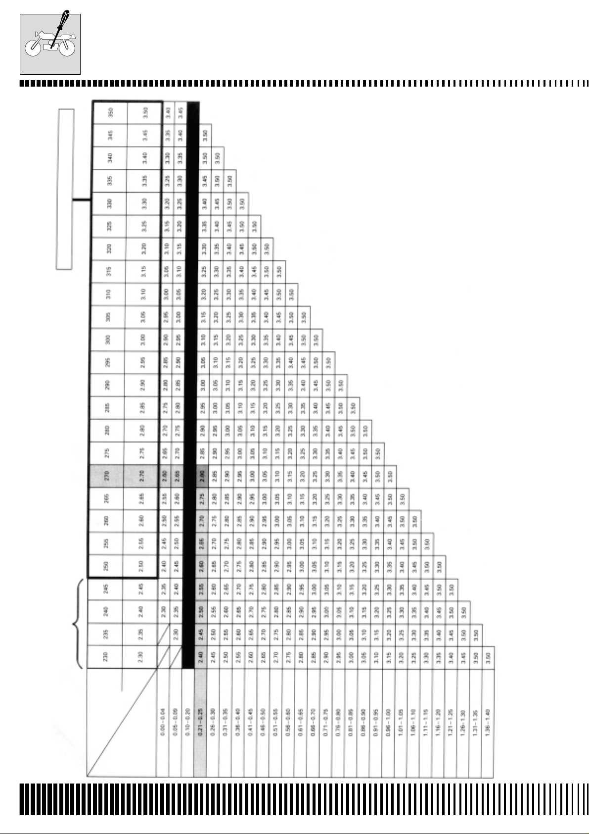
INTAKE VALVE PADS SELECTION TABLE
NO. (12892.41C00.XXX)
The valve tappet clearance is 0.23 mm
The thickness of the actual pad is 0.70 mm
HOW TO USE THIS TABLE:
1. Measure the clearance of the valve (cold engine).
2. Measure the thickness of the actual pad.
3. Make the vertical column (valve tappet clearance) and horizontal column (thickness) match.
The pad to use is 2.80 mm
SPECIFIED CLEARANCE/NO ADJUSTMENT NECESSARY
B.14
OPTIONAL
ACTUAL
SUFFIX NO.
MEASURED
(mm)
PAD
THICKNESS
CLEARANCE
(mm)
Page 23
VALVE PAD SET
(12800-41810)
MAINTENANCE
(EXHAUST SIDE)
FOR EXAMPLE
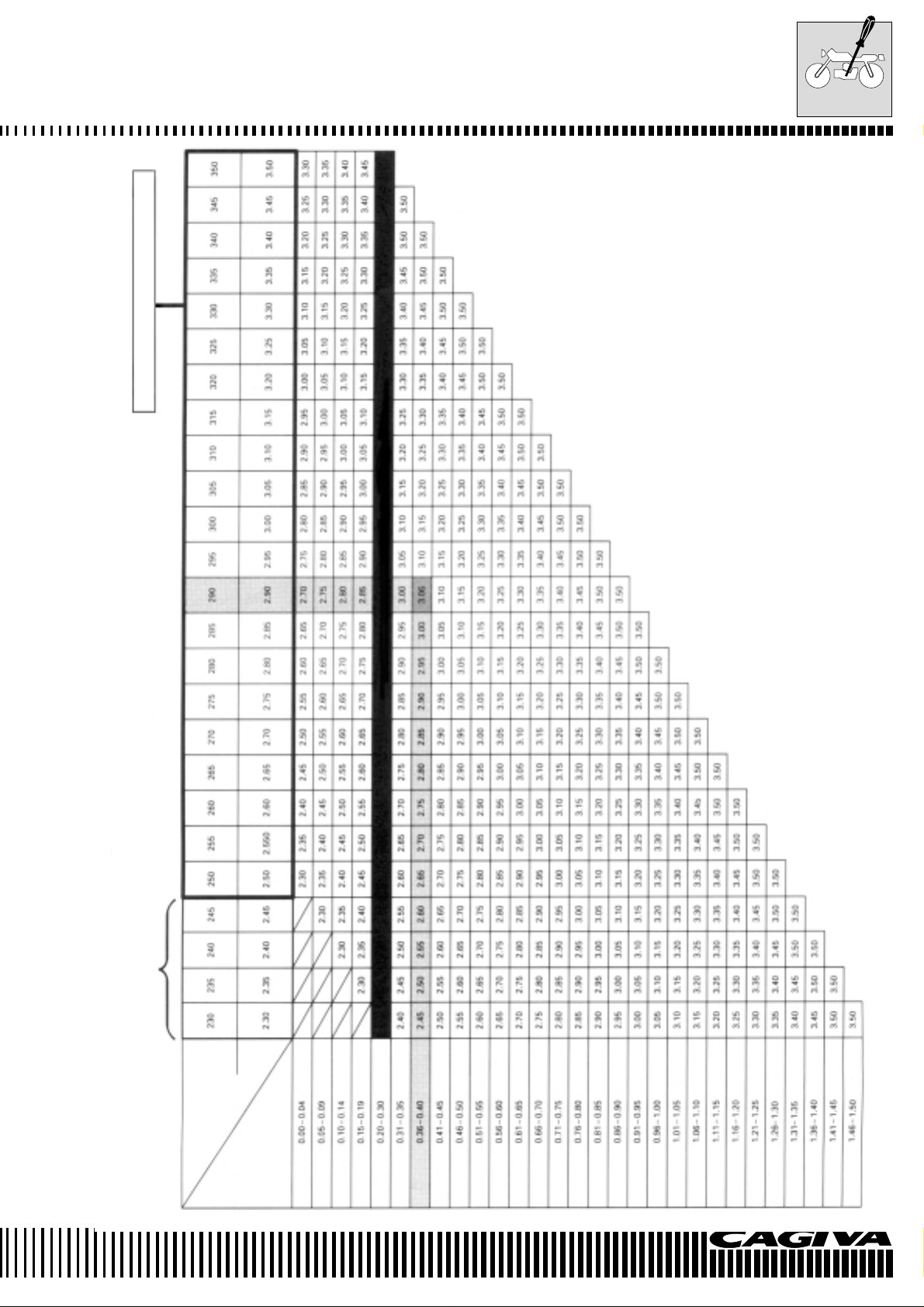
EXHAUST VALVE PADS SELECTION TABLE
NO. (12892.41C00.XXX)
The valve tappet clearance is 0.23 mm
The thickness of the actual pad is 0.70 mm
HOW TO USE THIS TABLE:
1. Measure the clearance of the valve (cold engine).
2. Measure the thickness of the actual pad.
3. Make the vertical column (valve tappet clearance) and horizontal column (thickness) match.
The pad to use is 2.80 mm
SPECIFIED CLEARANCE/NO ADJUSTMENT NECESSARY
OPTIONAL
SUFFIX NO.
ACTUAL
MEASURED
(mm)
PAD
THICKNESS
CLEARANCE
(mm)
B.15
Page 24
FUEL TUBING
MAINTENANCE
Check every 6000 km (or 6 months).
Substitute every 4 years.
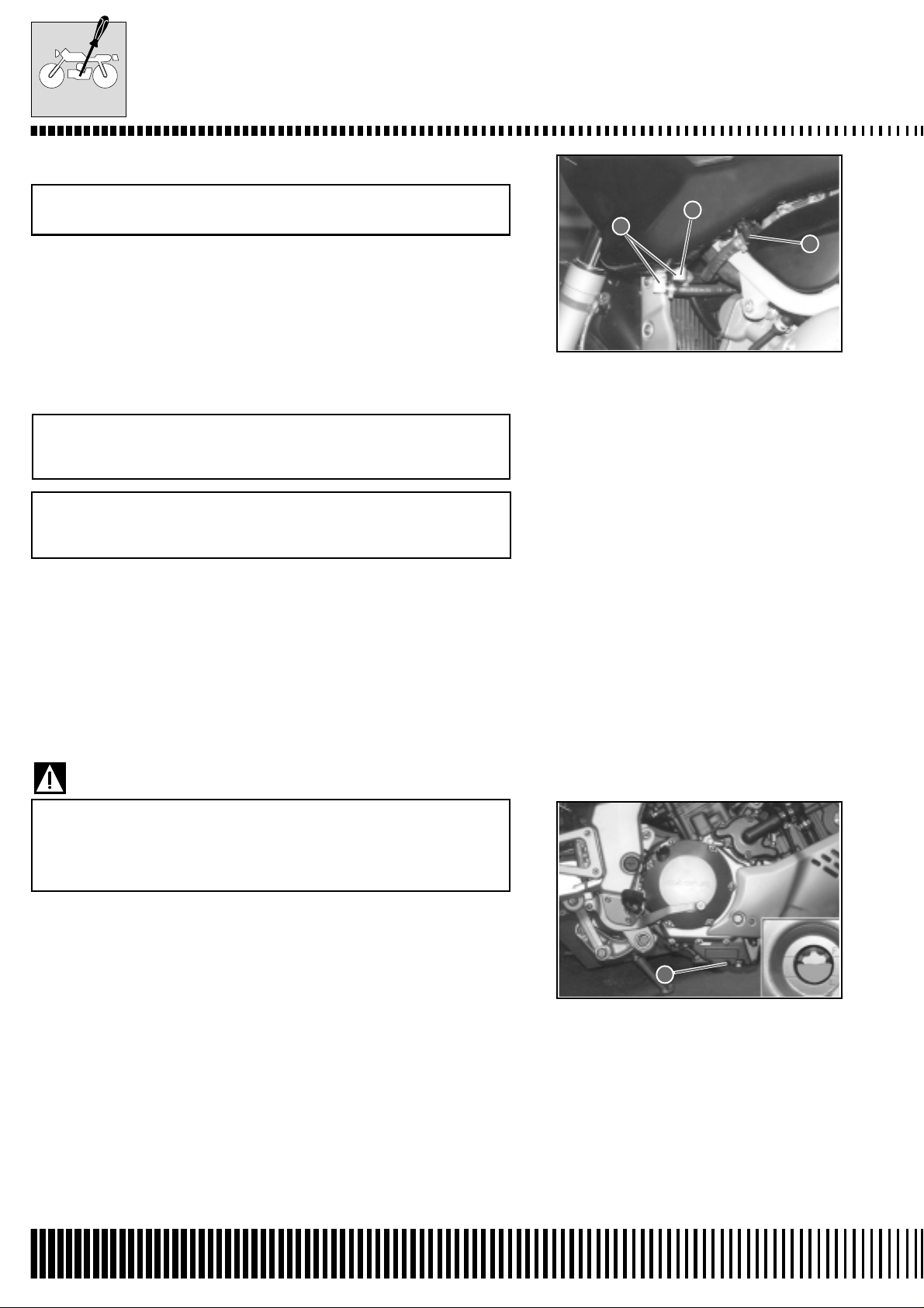
After removing the fuel tank, check to see if the feed tube 1 and
return tubes 2 and 3 are damaged or show signs of leaking. Substitute the tubes if any defects are found.
ENGINE OIL AND OIL FILTER
(ENGINE OIL)
Change at 1000 km (or 1 month).
Change every 6000 km (or 6 months).
(OIL FILTER)
Substitute at 1000 km (or 1 month).
Substitute every 18000 km (18 months).
The oil must be changed whilst the engine is hot. The oil filter must
be substituted at the above-mentioned intervals at the same time as
an oil change.
2
3
1
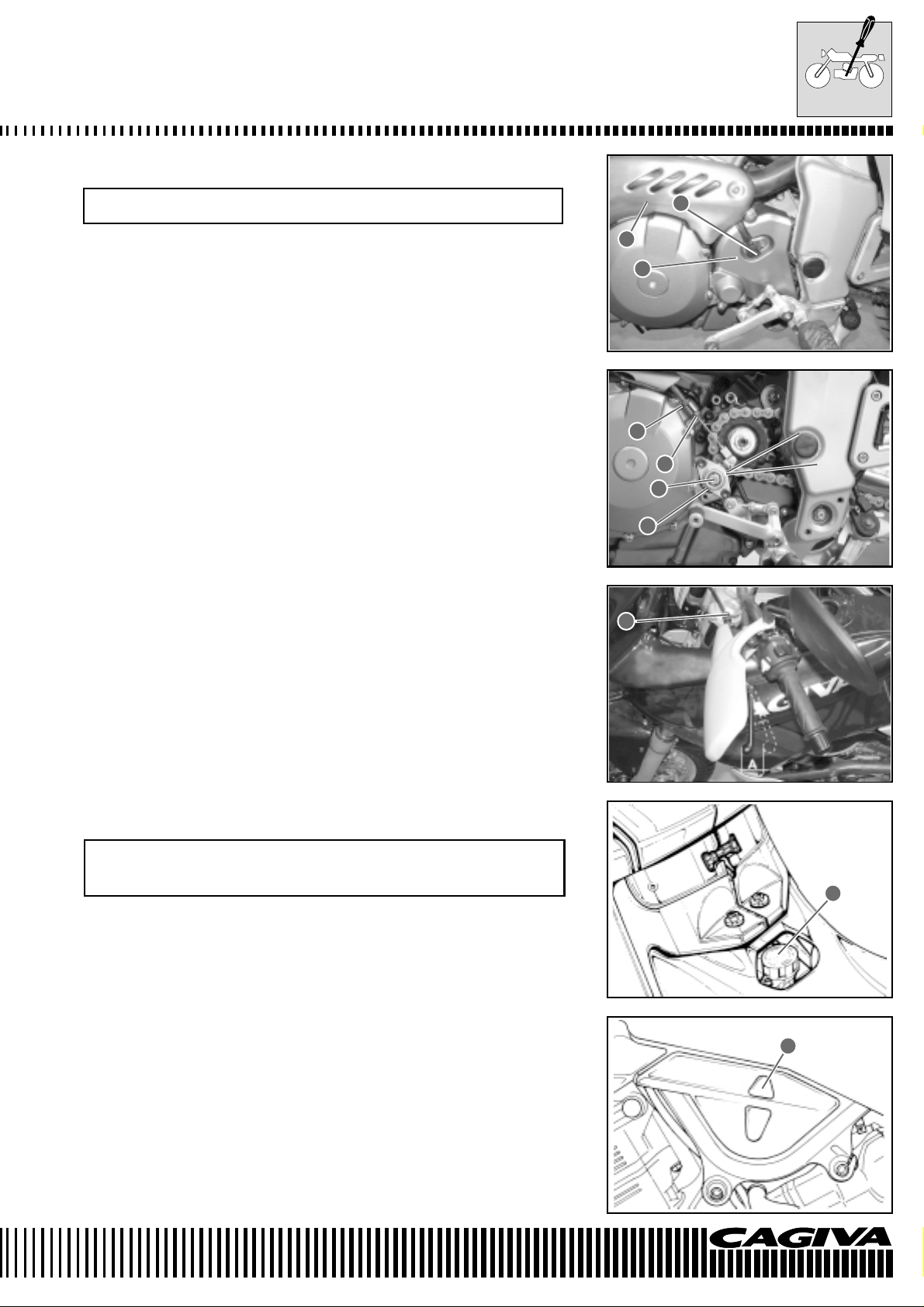
ENGINE OIL CHANGE
• Place the machine in a vertical position.
• Place a container underneath the engine and drain the used oil
into the container by unscrewing the sump plug 1 and the filling
plug 2.
Used oil contains dangerous substances that can damage
the environment. To change the oil it is recommended to
use our service network that can dispose of the oil respecting the environment and the norms in force.
• Tighten the sump plug 1 to the specified torque and pour new oil
into the filling hole 2. The engine holds 3.1 litres of oil. Use only oil
with an API SF or SG classification and a viscosity of SAE 10W/
40.
Torque pressure
Sump plug: 23 N.m (2.3 kg-m)
• Switch on the engine and leave it to heat up for several minutes.
• Switch off the engine and wait approximately one minute. Check
the oil level in the inspection window 3. If the level is below the
countersign “L”, add oil until it reaches the countersign “F”. If the
level exceeds the countersign “F” then discharge enough oil to
arrive at the countersign “F”.
1
B.16
Page 25
MAINTENANCE
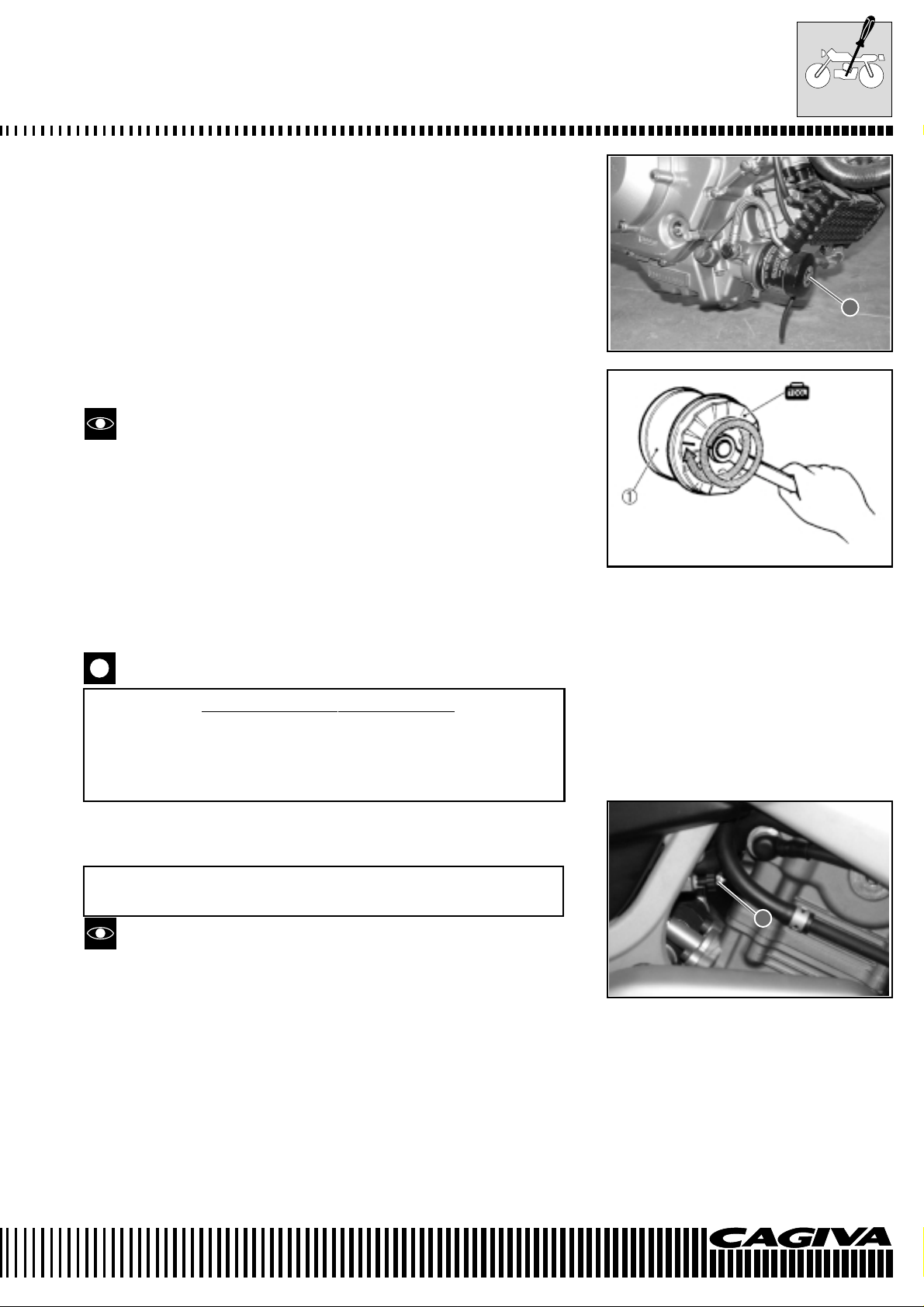
OIL FILTER SUBSTITUTION
• Drain the engine oil following the same procedure described for
the oil change.
• Remove the oil filter 1 utilising the appropriate wrench (special
tool).
• Apply a light layer of engine oil to the gasket of the new filter before assembly.
• Assemble the new filter by screwing it in by hand until the gasket
comes into contact with the oil filter container. Tighten by two turns
utilising the oil filter wrench (special tool).
Special tool: 800096659: Oil filter wrench
Tighten the filter correctly by utilising the special wrench.
Never tighten the oil filter by hand.
• Refill with new engine oil and check the level by following the same
procedure used for the oil change.
1
OIL CAPACITY
Oil change: 3.1 litres
Oil filter change: 3.3 litres
Engine overhaul: 3.6 litres
Utilise only
ORIGINAL CAGIVA OIL FILTERS. Filters and
spare parts of other makes could differ with regards to the
threading (diameter and pitch), filter performance and duration. Possible damage may occur to the engine with consequent loss of oil.
MINIMUM TICKOVER
Check at 1000 km (or 1 month).
Every 6000 km (or 6 months).
Carry out this adjustment when the engine is hot.
• Switch on the engine and adjust the tickover as specified by rotating the accelerator stop screw 1.
1
Minimum tickover:
1300±1350 rpm
B.17
Page 26
MAINTENANCE
ACCELERATOR CABLE PLAY
Check at 1000 km (or 1 month)
Every 6000 km (or 6 months).
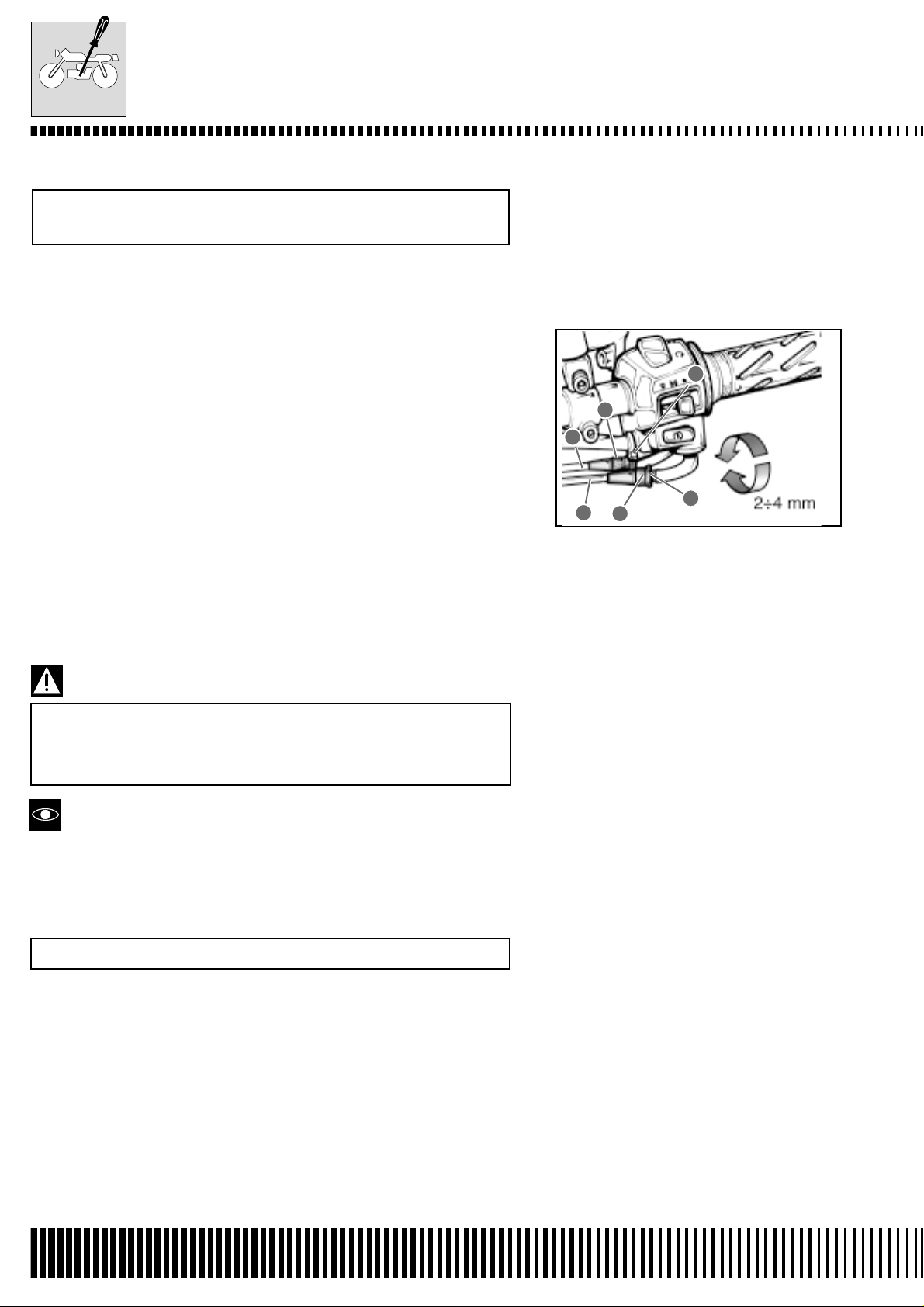
Adjust the accelerator cable play following these three phases.
First phase:
• Slacken the locknut 1 of the accelerator return cable B and completely screw in the screw adjuster 2.
Second phase:
• Slacken the locknut 3 of the accelerator opening cable A.
• Screw or unscrew the screw adjuster 4 until the accelerator cable
play is 2.0 – 4.0 mm at the accelerator handgrip.
• Tighten the locknut 3 whilst keeping the screw adjuster 4 locked in
position.
Third phase:
• Keeping the accelerator handgrip in the closed position, slowly
unscrew the screw adjuster 2 of the accelerator return cable B
until a resistance is felt.
• Tighten the locknut 1 whilst keeping the screw adjuster 2 locked in
position.
Accelerator cable play: 2.0-4.0 mm
After making the adjustments, check that the handlebar
movement does not cause an increase in the tickover. The
accelerator handgrip should return smoothly and automatically into position without any stiffness.
3
4
A
B
2
1
Greater adjustments can be carried out using the lateral adjuster on
the butterfly valve body of the carburettor.
SYNCHRONISA TION OF THE CARBURETTORS
Check every 12000 km (or 12 months)
(See page C-73)
B.18
Page 27
CLUTCH
MAINTENANCE
Check every 6000 km (or 6 months).
• Remove the speed sensor 1.
• Remove the left hand footrest from the frame by unscrewing the
two relative screws.
• Remove the engine pinion cover 2 by unscrewing the three relative screws.
• Remove the exhaust protection 3.
• Screw in the clutch lever assembly adjuster screw 8.
• Slacken the locknut 4 and completely unscrew the screw adjuster
5.
• Slacken the locknut 6 and rotate the screw adjuster 7 to obtain 5 10 degrees of play at the end of the clutch lever.
• Tighten the locknut 6.
• Slowly screw in the adjuster screw 5 until resistance is felt.
• Unscrew the screw adjuster 5 a
1
/4 of a turn and then tighten the
locknut 4.
• Screw or unscrew the screw adjuster 8 to obtain 10-15 mm of play
A at the end of the clutch lever.
Clutch lever play A: 10-15 mm
1
3
2
7
→
6
5
4
8
5°-10°
COOLING SYSTEM
Check every 1000 km (or 1 month)
Substitute the engine coolant every two years
ENGINE COOLANT LEVEL CHECK
The cooling of the engine is by forced circulation with a centrifugal
pump (situated on the left side of the engine), a by-pass valve thermostat and a radiator. The opening of the thermostat and the consequent flow of liquid in the radiator are activated when the temperature reaches ª 82°C. (maximum opening 95°C.). The system contains ª 2.3 litres of AGIP COOL engine coolant.
Make sure that the machine is on level ground and that it is in a
vertical position with both wheels placed on the ground.
Check that the level inside the expansion tank is between the MIN
and MAX levels shown on the left hand side of the machine 2.
If necessary , top up the engine coolant via the cap 1 positioned underneath the seat.
1
2
B.19
Page 28
MAINTENANCE
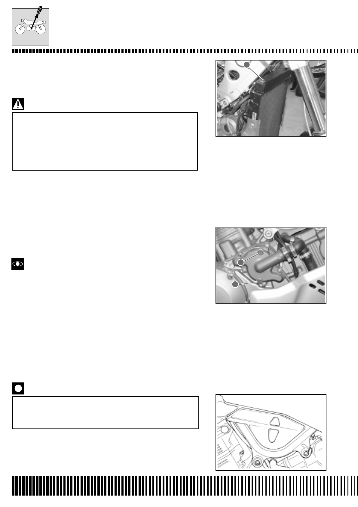
ENGINE COOLANT CHANGE
• After having removed the tank, remove the radiator cap 1, the
expansion tank cap and the drain plugs 2 end 3. Drain the engine
coolant.
* Do not remove the radiator cap when the engine is hot.
Boiling liquid or steam can cause serious burns.
* The engine coolant is harmful if swallowed or if it comes
into contact with the skin or the eyes. If the coolant comes
into contact with the skin or eyes, rinse abundantly with
water. If it is swallowed, provocate vomiting and immediately call a doctor.
• Wash the radiator with water if necessary.
• Tighten the coolant drain plugs 2 and 3 to the specified torque.
Torque pressure
Coolant drain plugs 2 and 3: 13 N.m (1.3 kg-m)
• Via the refill hole 5, fill the radiator with the specified engine coolant until it reaches the neck of the radiator.
• Bleed air out of the system via the bleed nut 2.
1
See chapter H for information regarding the engine coolant.
• Tighten the air bleed nut to the specified torque.
Torque pressure
Air bleed nut 4: 13 N.m (1,3 kg-m)
• Switch on the engine and completely bleed the air from the system via the radiator neck.
• Add engine coolant until it reaches the neck of the radiator.
• Tightly close the radiator cap 1.
• Add coolant until it reaches the maximum level of the expansion
tank.
• Tightly close the expansion tank cap.
• Heat up the engine and then let it cool. Add engine coolant until
the upper level mark of the tank.
Repeat the above-mentioned procedure several times to
check that the radiator is completely full of engine coolant. The upper level of the coolant is shown on the side of
the tank.
2
3
Engine coolant capacity: 2000 ml
B.20
Page 29
MAINTENANCE
RADIATOR TUBES
• Remove the sump guard protection 5 by unscrewing the two screws
6 indicated in the figure. Push it aside in the direction of the arrow.
Check to see if the radiator tubes are damaged, cracked or leak. If
any defect is found, substitute the tubes immediately.
TRANSMISSION CHAIN
Check at 1000 km (or 1 month)
Every 6000 km (or 6 months)
Clean and lubricate every 1000 km.
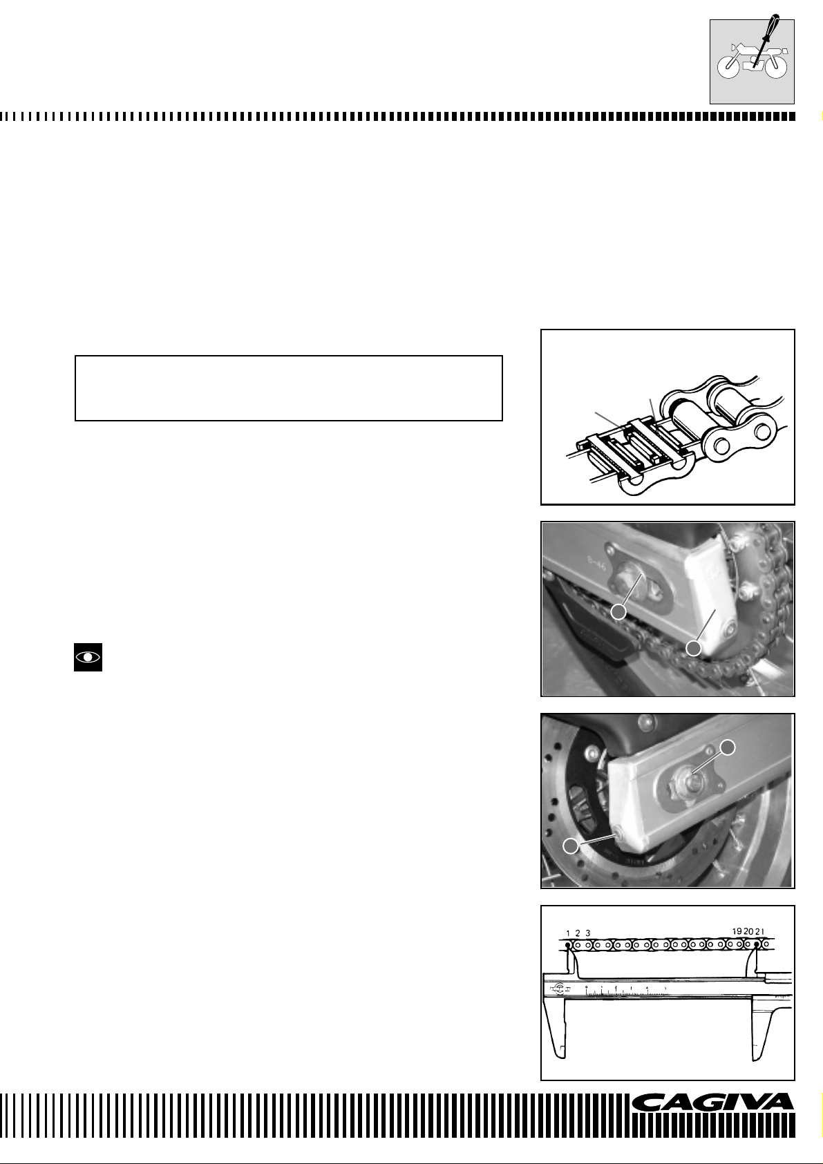
Visually check the transmission chain for the following defects. Put
the machine on a jack and a block of wood. Slowly rotate the rear
wheel by hand with the engine in neutral.
* Slack pins * Excessive wear
* Damaged rollers * Incorrect chain adjustment
* Dry or rusty links
* Missing O-rings * Bent or seized links
Grease
O-ring
The chain must be substituted if any one of these defects is found.
Substitute also the crown and pinion wheels when substituting the
transmission chain.
CHECK
• Slacken the axle nut 1.
• Completely tighten the chain by adjusting the screw adjusters 2.
• Count 21 pins (20 pitches) of the chain and measure the distance
between the two points. If the distance exceeds the operating limits, the chain must be substituted.
1
2
1
2
Operating limit (20 pitches of the transmission chain):
323 mm
B.21
Page 30
MAINTENANCE
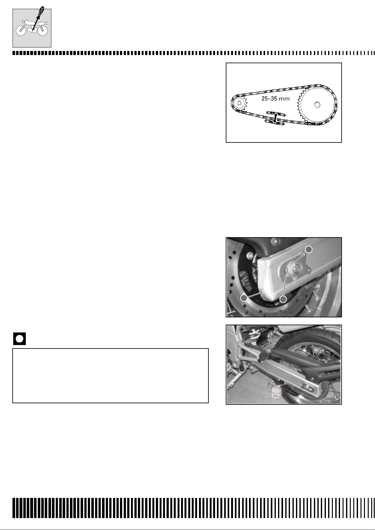
CHAIN ADJUSTMENT
• Slacken or tighten both chain screw adjusters 1 until the chain
reaches a slack of 25-35 mm in the central position of the chain
between the crown and pinion. The marks A on both screw adjusters must be in the same position of the scale to ensure the correct
alignment of the wheel.
• To make accurate adjustments, place the machine on the side
stand.
• After having correctly adjusted the chain, tighten the axle nut 2 to
the specified torque.
• Recheck the chain slack after having tightened the axle nut 2.
Torque pressure
Rear axle nut: 63,7÷ 68,6 N·m (6,5 ÷ 7 kg-m)
CLEANING AND LUBRICATION
• Wash the chain with kerosene. If the chain tends to rust quickly,
shorten the maintenance intervals.
Do not use Trichloroethylene, petrol or other similar liquids. These liquids possess an excessive solvent power
and more importantly, can damage the O-rings that keep
the grease inside the spaces between the rollers and pins.
Long life of the chain depends on the presence of grease
in these spaces.
• After having washed and dried the chain, grease it with high viscosity engine oil or with lubricants specifically produced for chains
with O-rings.
2
1
A
B.22
Page 31

BRAKES
MAINTENANCE
(BRAKES)
Check at 1000 km (or 1 month)
Every 6000 km (or 6 months)
(BRAKE AND BRAKE FLUID TUBING)
Check every 6000 km (or 6 months). Substitute the tubes
every four years. Substitute the brake fluid every two years.
BRAKE FLUID LEVEL CHECK
• Place the machine in a vertical position with the handlebars straight.
• Check the level of the brake fluid by observing the minimum level
mark on the front 1 and rear 2 brake fluid chambers.
• If the level is inferior to the minimum level mark, add brake fluid to
the following specification.
Specification and classification: DOT 4
The braking system of this machine has been filled with
glycol-based brake fluid. Do not use or mix different types
of fluids such as silicone or petrol-based fluids. Do not
use brake fluid from old, used or non-sealed containers.
Do not use leftover fluids from previous maintenance or
left for long periods of time.
1
2
Spillage or leaks of brake fluid are dangerous and immediately discolour painted surfaces. Check the brake tubing and joints for cracks or leaks before riding.
BRAKE PADS
• Remove the blocking plates 1 and the locating pins.
• Pull out the pads from underneath.
The wear of the pads can be visually checked by observing the
groove A on the surface of the pad. When the groove disappears, it
is necessary to substitute the pads (see chapter about the braking
system).
When reassembling, make sure that the pads are completely inserted into their positions. Consult the chapter
about the braking system.
1
A
B.23
Page 32

MAINTENANCE
• To change the rear brake pads, proceed as follows:
• Remove the two screws of the rear spray guard 3 rotate it as shown
in the figure.
Substitute the pads in pairs to guarantee maximum braking performance..
BRAKE PEDAL HEIGHT
The rear brake pedal must have a travel of 10-15 mm before the
braking action takes place. If it is necessary, make the adjustment as
follows:
- Slacken the nut 5;
- Using nuts 6 or 7, position the pedal in the desired position.
- When the adjustment is completed, tighten the nut 7.
Torque pressure
Rear brake pedal locknut 1: 18 N.m (1.8 kg-m)
3
1
MAINTENANCE
To change the rear brake disc pads, proceed as follows:
- Remove the 2 screws 1 of the rear mudguard 2 and rotate it as
shown in the figure.
- Remove the pincer assembly from the forks by unscrewing the
2 relative screws 3.
- Remove the 2 pins 4 that keep the pads in place.
Proceed with checking the pads for wear in the same way as for
the front brake pads.
Reassemble everything in the reverse order of removal.
5
6
7
4
3
1
1
2
B.24
Page 33

MAINTENANCE
BLEEDING THE AIR FROM THE BRAKING SYSTEM
The air that is trapped in the braking system acts as a cushion, absorbing the greater part of the pressure exerted by the brake pump.
The performance of the brake pincer is therefore compromised. The
presence of air in the system is indicated by a “sponginess” of the
brake lever or pedal and a reduction in the braking performance. As
this situation could be highly dangerous for both rider and the machine, it is necessary to effect the bleeding of the air from the braking system immediately following maintenance on the brakes. This
procedure is carried out as follows:
• Refill the brake fluid chamber with brake fluid until it reaches the
“UPPER” mark.
• Replace the chamber cover to avoid the entry of dirt.
• Remove the rubber cap and apply a plastic tube to the bleed valve
nipple. Insert the free end of the tube in a container.
Torque pressure
Air bleed valve nipple: 7.5 N.m (0.75 kg-m)
• Front brake: bleed out the air via the bleed valve nipple.
• Squeeze and release the brake lever several times in rapid succession and then squeeze it without releasing the lever. Slacken
the bleed valve nipple rotating it a 1/4 of a turn so that the fluid can
pour out into the container. This releases the tension on the brake
lever and allows it to move towards the handgrip of the handlebar.
Close the valve, squeeze and release the brake lever again and
reopen the valve. Repeat this operation until the fluid that pours
into the container does not contain bubbles of air.
• The bleeding must be carried out on both front brake pincers at
the same time.
During the bleeding of the brake system, top up the brake fluid chamber with brake fluid as necessary . There must always be brake fluid
in the chamber.
• Close the bleed valve nipple and disconnect the plastic tube. Refill
the brake fluid chamber with brake fluid until the fluid reaches the
“UPPER” mark.
Handle brake fluids with care. They chemically react with
paint, rubber, etc.
• The only difference in the procedure for the rear brake is that it is
a pedal and not a lever that activates the brake.
B.25
Page 34

MAINTENANCE
TYRES
Check every 6000 km (or 6 months)
CONDITION OF THE TREAD
Badly worn tyres decrease the road holding and are therefore dangerous. It is recommended that tyres be changed when the tread reaches
the minimum level.
Operating limit
Tread depth (front): 2.0 mm
(rear): 2.0 mm
TYRE PRESSURES
If the tyre pressures are too high or too low, the steering is negatively influenced and tyre wear is accelerated.
Maintain the correct tyre pressures to obtain the maximum road
holding and the maximum life from the tyres.
Cold tyre pressures are as follows:
COLD TYRE RIDER ONLY RIDER + PASS.
PRESSURE
kPa kg/cm
2
kPa kg/cm
2
FRONT 220 2,2 240 2,4
REAR 240 2,4 260 2,6
The standard tyres mounted on this machine are 110/80 –
18” for the front wheel and 150/70 – 17” for the rear wheel.
The use of different tyres to those specified could cause
instability . It is highly recommended to use tyres of the prescribed size.
TYRE TYPE
TUBELESS
STEERING
Check at 1000 km (or 1 month)
Every 12000 km (or 12 months)
The steering must be adjusted correctly to obtain a smooth rotating
action of the handlebar and a safe ride. Steering that is too stiff
obstructs the smooth rotation of the handlebars whilst steering that
is too slack brings poor stability to the machine. Place the machine
on its stand so that the front wheel is raised from the ground. Grip
the forks where the wheel hub is and pull forwards to check that the
steering head play is not excessive. If excessive play is found, carry
out the adjustment of the steering bearings as described in the Suspension chapter of this manual.
B.26
Page 35

MAINTENANCE
COMPRESSION TEST
The compression of a cylinder is an optimum indicator of the internal condition of the engine.
The decision to overhaul the engine is often the result of a compression test. Amongst the periodical maintenance
data to be found at the dealer are also the compression measurements for each maintenance operation.
COMPRESSION SPECIFICATION (automatic decompression activated)
Standard Limit Difference
1300-1700 kPa 1100 kPa 200kPa
( 13-17 kg/cm
Low compression could indicate one of the following conditions:
* Worn piston or piston rings
* Piston rings seized in the grooves
* Poor valve closure
* Head gasket broken or defective
2
) ( 11 kg/cm2 ) ( 2 kg/cm2 )
Overhaul the engine in the following cases:
* The compression of one of the cylinders is less than 1100 kPa (11 kg/cm
2
).
* The difference between the compression of the two cylinders is more than 200 kPa.
* All values of the compression are less than 1300 kPa (13 kg/cm2) even if they are more than 1100 kPa (11 kg/cm2).
COMPRESSION TEST PROCEDURE
* Before verifying the engine compression, check that the cylinder head bolts are tightened to the correct torque
and that the valves are adjusted correctly.
* Heat up the engine before proceeding with the test.
* Check that the battery is fully charged.
• Carry out the compression test as follows:
• Remove the seat and the plastic underneath the seat.
• Remove both spark plugs (see page B-7.)
• Screw in the compression meter in one of the spark plug holes
making sure that it is correctly tightened.
• Keep the accelerator handgrip in the fully open position.
• Turn over the engine with the electric starter motor for several
seconds and note the maximum reading of the compression me-
ter. This is the compression of that cylinder.
• Repeat the procedure for the other cylinder.
Special tool: 800096660: Compression meter
800096652: Compression sensor adaptor
B.27
Page 36

MAINTENANCE
OIL PRESSURE TEST
Periodically check the oil pressure for an approximate evaluation of the condition of the moving parts of the engine.
OIL PRESSURE SPECIFICATION
More than 300 kPa (3.0 kg/cm2) at 3000 rpm, oil temperature
60°C. Less than 600 kPa (6.0 kg/cm
If the pressure of the oil is more or less than those specified, consider the following causes:
LOW OIL PRESSURE
* Oil filter blocked
* Oil leak in the system
* O-ring damaged
* Defective oil pump
* One or more of these problems together
HIGH OIL PRESSURE
* Excessive oil viscosity
* Oilways blocked
* Or both problems together
2
)
OIL PRESSURE TEST PROCEDURE
Switch on the engine and check that the oil pressure warning light is
illuminated. If it remains illuminated, check the electrical circuit of the
oil pressure warning light. If the circuit is in good condition, check the
oil pressure as follows:
• Remove the plug from the main oil way.
• Insert the oil manometer along with its attachment in the position
indicated.
• Heat up the engine as follows:
Summer: 10 minutes at 2000 rpm
Winter: 20 minutes at 2000 rpm
• After the heating up, increase the speed to 3000 rpm (check the
revcounter) and take the reading of the oil manometer.
Special tool: 80009661: oil pressure measuring tube
800096662: oil pressure measuring adaptor
800096663: instrument (for high pressures)
Torque pressure
Main oil way plug: 10 N.m (1.0 kg-m)
B.28
Page 37

TECHNICAL DATA
MAINTENANCE
VALVE + GUIDE
PART STANDARD LIMIT
Valve diameter Intake 40 –––––
Exhaust 33 –––––
Valve tappet clearance (cold) Intake 0.10-0.20 –––––
Exhaust 0.20-0.30 –––––
Valve stem/guide play Intake 0.010-0.037 –––––
Exhaust 0.030-0.057 –––––
Valve stem distortion Intake and
Exhaust
Valve guide – internal diameter Intake and
Exhaust
Valve stem – external diameter Intake 5.475-5.490 –––––
Exhaust 5.455-5.470 –––––
Valve stem decentralising Intake and
Exhaust
Valve head thickness Intake and
Exhaust
Valve seat width Intake and
Exhaust
Valve head radial decentralising Intake and
Exhaust
Valve spring floating width Internal –––––– 37.0
(intake and exhaust) External –––––– 40.7
Valve spring tension Internal 6.2 kg at 33.1 mm length –––––
(intake and exhaust) External 15.4 kg at 36.6 mm length –––––
–––––– 0.35
5.500-5.512 –––––
–––––– 0.05
–––––– 0.5
0.9-1.1 –––––
–––––– 0.03
Unit: mm
CAMSHAFT + CYLINDER HEAD
PART STANDARD LIMIT
Cam height Intake 37.770-37.838 37.47
Exhaust 36.380-36.448 36.08
Camshaft seat pin oil play Intake and
exhaust
Camshaft seat support Intake and
internal diameter exhaust
Camshaft seat pin external diameter Intake and
exhaust
Camshaft decentralising Intake and
exhaust
Intermediate gearing push play/N° 2
timing sprocket 0.15-0.29
Cylinder head deformation –––––– 0.05
0.019-0.053 0.150
22.012-22.025 –––––
21.972-21.993 –––––
––––– 0.10
–––––
Unit: mm
B.29
Page 38

MAINTENANCE
CYLINDER + PISTON + PISTON RINGS
Unit: mm
PART STANDARD LIMIT
Compression pressure 1300-1700 kPa 1100 kPa
(automatic decompression activated)
Compression pressure difference
(13-17 kg/cm2) (11 kg/cm2)
––––––
200 kPa
(2 kg/cm
2
)
Piston/cylinder play 0.015-0.025 0,12
Cylinder diameter 98.000-98.015 Lines or scratches
Piston diameter 97.980-97.995
97.880
Measured 10 mm from the base of the skirt
Cylinder deformation –––––– 0.05
Piston ring floating end play 1st Approx. 6.8 5.4
2nd Approx. 9.9 7.9
Piston ring end play 1st 0.15-0.35 0.5
2nd RN 0.15-0.30 0.5
Piston ring/groove play 1st –––––– 0.18
2nd –––––– 0.15
Piston ring groove width 1st 0.93-0.95 –––––
1.55-1.57 –––––
2nd 1.01-1.03 –––––
Oil scavenger ring
Piston ring width 0.84-0.89 –––––
1st
2.51-2.53 –––––
1.40-1.42 –––––
2nd 0.97-0.99 –––––
Gudgeon pin hole - internal diam. 22.002-22.008 22.030
Gudgeon pin - external diameter 21.992-22.000 21.980
CONNECTING ROD + CRANKSHAFT
Unit: mm excluding the
ratios
PART STANDARD LIMIT
Connecting rod big end - int. diam. 22.010-22.018 22.040
Connecting rod small end - lateral play
0.17-0.32 0.50
Connecting rod small end – width 21.95-23.00 –––––––
Gudgeon pin length 44.17-44.22 –––––––
Small end oil play 0.032-0.056 0.080
External diameter - Gudgeon pin 44.976-45.000 –––––––
Seat pivot oil play 0.018-0.045 0.080
External diameter – seat pivot 47.985-48.000 ––––––
Crankshaft axial play 0.050-0.100 ––––––
Crankshaft bearing shell thickness 1.925-2.175 ––––––
B.30
Page 39

MAINTENANCE
OIL PUMP
PART STANDARD LIMIT
Oil pump reduction ratio 1.301 (57/31 x 29/41) –––––
Oil pressure (at 60°C.) More than 300 kPa (3.0 kg/cm
2
) at 3000 rpm –––––
CLUTCH
PART STANDARD LIMIT
Clutch lever play 10-15 –––––
Clutch main plate thickness 2.92-3.08 –––––
Clutch main plate teeth width ––––– 12.9
Clutch disengagement screw 1/4 of a turn backwards –––––
Clutch main plate deformation ––––– 0.10
Clutch spring floating length ––––– 29.6
THERMOSTAT + RADIATOR + FAN
PART STANDARD LIMIT
Thermostat valve opening temp. 82° C –––––
Thermostat valve lifting up temp. 95° C –––––
Radiator cap valve opening
pressure
Fan thermal switch
activating temperature
Coolant sensor 20° C Approx. 2.45 kΩ –––––
resistance 50° C Approx. 0.811 kΩ –––––
temperature 80° C Approx. 0.318 kΩ –––––
OFF➝ ON
ON➝ OFF
110° C Approx. 0.142 kΩ –––––
130° C Approx. 0.088 kΩ –––––
110 kPa (1,1 kg/cm2)
Approx. 105° C –––––
Approx. 100° C –––––
GEARCHANGE + TRANSMISSION CHAIN
PART STANDARD LIMIT
Primary reduction ratio 1.838 (57/31) –––––
Secondary reduction ratio 2.235 (58/17) –––––
Gear ratios 1st 2.666 (32/12) –––––
2nd 1.933 (29/15) –––––
3rd 1.500 (27/18) –––––
4th 1.227 (27/22) –––––
5th 1.086 (25/23) –––––
6th 1.000 (24/24) –––––
Crown/pinion ratio 2.562 (41/16) –––––
Gearchange fork play 0.1-0.3 0.50
Gearchange fork width 5.0-5.1 –––––
Gearchange fork thickness 4.8-4.9 –––––
Transmission chain Type Regina 136 ORP –––––
Links 106 links –––––
Length: 20 pitches
––––– 323
Unit: mm excluding the
ratios
–––––
Unit: mm excluding ratios
B.31
Page 40

MAINTENANCE
PART STANDARD LIMIT
Transmission chain slack 25-35 –––––
Gearlever travel 5 –––––
Rear brake lever travel 10÷15 –––––
INJECTOR + FUEL PUMP + FUEL PRESSURE ADJUSTER
P ART TECHNICAL CHARACTERISTICS NOTES
Injector resistance 11-16 ohms at 20°C.
Fuel pump flow Approx. 1 litre per minute at 290 kPa (2.9 kg/cm2)
Fuel pressure adjuster Approx. 290kPa (2.9 kg/cm
2
)
operating pressure
FI SENSOR + AIR INTAKE CONTROL VALVE
P ART TECHNICAL CHARACTERISTICS NOTES
CMP sensor resistance 0.9-1.3 kΩ
CMP sensor peak voltage More than 0.8 V
CKP sensor resistance 184-276 Ω
CKP sensor peak voltage More than 4 V
IAP sensor incoming voltage 4.5-5.5 V
IAP sensor outgoing voltage Approx. 1.8 V at minimum
TP sensor incoming voltage 4.5-5.5 V
TP sensor resistance (closed) Approx. 1.2 kΩ
(open) Approx. 4.4 kΩ
TP sensor outgoing (closed) Approx. 1,1 V
voltage (open) Approx. 4.2 V
ECT sensor incoming voltage 4.5-5.5 V
ECT sensor resistance 2.3-2.6 KΩ a 20° C
IAT sensor incoming voltage 4.5-5.5 V
IAT sensor resistance 2.2-2.7 kΩ a 20° C
AP sensor incoming voltage 4.5-5.5 V
AP sensor outgoing voltage Approx. 3.6 V at 760 mmHg (100 kPa)
TO sensor resistance 60-64 KΩ
TO sensor voltage Approx. 2.5 V
GP sensor voltage More than 0.6 V (from the 1st to the 6th)
Injector voltage Battery voltage
Primary ignition coil peak voltage More than 280 V (when the engine turns)
VCSV resistance 36-44 kΩ
Air intake control valve
operating rpm
B.32
Opening rpm More than 4000 rpm
Closing rpm Les than 3800 rpm
Page 41

MAINTENANCE
CARBURATORE
P ART TECHNICAL CHARACTERISTICS
Minimum rpm - choke 2000 rpm at 20°-30° 3500-4000 at 90°
Minimum rpm – tickover 1300-1350 rpm
Accelerator cable play 2.0-4.0 mm
ELECTRICAL SYSTEM
P ART TECHNICAL CHARACTERISTICS NOTES
Timing synchronisation 3° BTDC at 1200 rpm
Firing order1·2
Spark plugs Type NGK: CR8EK
Denso:U24ETR
Electrode
gap
Spark performance More than 8 at 1 atm.
Camshaft position sensor
resistance
Ignition coil resistance Low 3-5 Ω + terminal / - terminal
High 20-28 kΩ
Camshaft position sensor
peak voltage
Primary ignition coil peak voltage More than 280 V
Generator winding resistance 0.1-1.0 Ω Y - Y
Max. outgoing wattage-generator Approx. 380W at 5000 rpm
Generator voltage without a
charge (cold engine)
Ignition relay resistance 3-6 Ω
Battery Type FIAMM 6E9
Capacity 12V (9 Ah) 32.4kC
Standard electrolyte
density
Fuses Headlight HI 15A
LO 15A
Direction
indicators
Injection
relay
Main fuse
More than 70V (CA) at 5000 rpm
184-276 Ω BI-G
More than 4,0 V
1.265÷1.275
0.6-0.7
15A
10A
15A
Unit: mm excluding ratios
+ terminal / spark plug
insulated cover
B.33
Page 42

MAINTENANCE
WATTAGE
P ART TECHNICAL CHARACTERISTICS
Headlight HI 60
LO 55
Sidelight 5
Stop/tail light 21/5
Direction indicators 10
Revcounter light 1.2
Direction indicator warning light 2
Main beam warning light 2
Neutral warning light 2
Fuel level warning light 2
Number plate light 5
BRAKES + WHEELS
PART STANDARD LIMIT
Rear brake pedal travel 5 –––––
Brake disc thickness Front 4.0±0.2 3.5
Rear 5.0±0.2 4.5
Brake disc deformation
(front and rear)
Wheel deformation Axial < 0.5 2
(front and rear) Radial < 0.8 2
Wheel spindle axial deformation
Front
Rear
––––– 0.30
< 0.1 0.2
Unit: W
Unit: mm
B.34
Page 43

MAINTENANCE
PART STANDARD LIMIT
Axial deformation – wheel Front –––––– 0.5
Rear ––––– 0.5
Wheel dimensions Front 3.00“X18” –––––
Rear 4.25 “X17”
Tyre dimensions Front 110/80 -18” –––––
Rear 150/70 -17” –––––
Tread depth Front ––––– 2.0
Rear ––––– 2.0
SUSPENSION
PART STANDARD LIMIT
Fork travel 150 –––––
Fork spring floating length 280 –––––
Fork oil level 180 –––––
Rear spring assembly
installed length
Rear wheel travel 160 –––––
Fork shaft pin deformation ––––– 0.30
180 –––––
TYRE PRESSURES
COLD TYRE RIDER ONLY WITH PASSENGER
PRESSURES kPa kg/cm
FRONT 220 2.2 240 2.4
REAR 240 2.4 260 2.6
2
kPa kg/cm
2
B.35
Page 44

MAINTENANCE
FUEL + COOLANT
P ART TECHNICAL CHARACTERISTICS NOTES
Fuel type The fuel must be 95 octane petrol or higher.
It is recommended that lead free petrol be used.
Fuel tank capacity 20 L
Engine oil type AGIP TEC 4T 10W/40 SINT 20005W/40
Engine oil capacity Oil change 3100 ml
Filter change 3300 ml
Overhaul 3600 ml
Fork oil type SAE 7.5
Fork oil capacity
(each leg)
Brake fluid type AGIP BRAKE 4
Coolant type Use antifreeze coolant that is compatible
with aluminium radiators. Mix with a
ratio of 50/50 with distilled water only.
Coolant capacity
680 cc
2000 ml
B.36
Page 45

INJECTION - AIR INTAKE SYSTEM
Section
C
C.1
Page 46

INJECTION - AIR INTAKE SYSTEM
Maintenance precautions ....................................................... C-3
FI system technical characteristics ........................................ C-9
Intake air system technical characteristics............................. C-21
FI system - position of parts ................................................... C-26
FI system diagram.................................................................. C-27
FI system - electrical diagram ................................................ C-28
Auto-diagnostic function......................................................... C-29
Security function..................................................................... C-32
FI system diagnostics............................................................. C-33
Fuel feed system.................................................................... C-51
Butterfly body ......................................................................... C-55
Intake air system .................................................................... C-78
Sensors .................................................................................. C-80
C.2
Page 47

INJECTION - AIR INTAKE SYSTEM
MAINTENANCE PRECAUTIONS
Observe the following when handling components of the FI system
or when carrying out maintenance on the system.
CONNECTORS/COUPLINGS
• When putting connectors together , make sure that the connectors
are pushed fully home until a click is heard.
• When pulling apart a snap connector , release the stop before disconnecting. When connecting, push in until a click is heard.
• When disconnecting a coupling, make sure to grip the body of the
coupling and do not pull on the leads.
• Check that the terminals of each connector/coupling are not loose
or bent.
• Check for corroded or dirty terminals. A good contact will not be
made if the terminals are corroded and not perfectly clean.
Click
Click
• If there are circuit problems, check each lead by hand. If there are
cracks or breaks in the insulation, repair or substitute the leads.
• When carrying out measurements on electrical connectors with a
tester, insert the probe into the connector from the wiring system
side of the connector/coupling.
• If it is not possible to insert the probe from the wiring side, take
particular care not to bend the male terminal or open the female
terminal when inserting the probe on the terminal side of the coupling.
Never insert the probe into a male terminal.
• Check terminal connections to see if the male terminals are bent
or the female terminals are too open or both terminals are loose,
corroded or dirty.
2
1
1
Coupling
Probe
2
2
3
Coupling
1
Probe
2
3
Male terminal
1
2
C.3
Page 48

INJECTION - AIR INTAKE SYSTEM
FUSES
• Always search for the cause of a blown fuse. Eliminate the cause
and then substitute the fuse.
• Use only fuses of the correct amperage.
• Do not use wire or another substitute for a fuse.
ECM/VARIOUS SENSORS
• Seeing that each component is a high precision part, take care to
not damage the said components during the removal/installation
phases.
INCORRECT
• Take care to not touch the electrical terminals of the ECM. The
static electricity of the body can damage the component.
• Before connecting or disconnecting an ECM coupling, make sure
that the ignition switch is in the OFF position. This will prevent
damage to the electronic parts.
• Do not connect the battery with inverted polarities. This will instantly damage components of the FI system when the circuit is
switched on.
ignition switch
INCORRECT
C.4
Page 49

INJECTION - AIR INTAKE SYSTEM
• Do not remove the terminals of the battery whilst the engine is
running.
If a terminal is removed, this would cause an inverted electrical
force that would seriously damage the ECM.
• Before measuring the voltage on any terminal of the electrical system, check that the voltage of the battery is 11V higher. Terminal
checks carried out with an insufficient battery voltage can cause
diagnostic errors.
• Never connect any tester (voltmeter, ampmeter, etc.) to the ECM
when its coupling is disconnected. This could cause damage.
• Never connect an ohmmeter to the ECM with the coupling connected. This could cause damage to the ECM and the sensors.
• Use a good quality ohm-meter/voltmeter. It will not be possible to
obtain precise test results or possible personal injuries could result if bad quality equipment is used.
ELECTRICAL CIRCUIT TESTING PROCEDURE
There are various methods of testing electrical circuits. The one
described here is the general method for testing open circuits or
short circuits using an ohmmeter and a voltmeter.
OPEN CIRCUIT TESTS
The probable causes of open circuits are described as follows. Check
the connectors/couplings and terminals with particular attention because these are frequently the cause of an open circuit.
• Loose connection of a connector/coupling.
• Poor contact of the terminal (because of dirt, corrosion, rust or
foreign objects, etc.).
• Leads not insulated properly.
• Poor connection between the lead and the terminal.
C.5
Page 50

INJECTION - AIR INTAKE SYSTEM
• Disconnect the negative polarity cable from the battery.
• Check to see if the connectors/couplings and both ends of the
circuit are not loose. Also check the snap-fit couplings for correct
insertion.
• Check the tightness of the female terminals of the circuit by using
a test male terminal.
Visually check each terminal for poor contacts (caused by dirt,
corrosion, rust, foreign bodies, etc.). Check that each terminal is
correctly inserted into the couplings.
If the terminal is loose, adjust it to increase the tightness or substitute the terminal. They must be clean and free of corrosion that
could impede a good contact.
• Using the continuity and voltage testing procedure described as
follows, check for an open circuit or a poor contact of the wiring
terminals. Locate the defect and repair..
1
Sensor
Check to see if the connection is loose
1
Check the contact pressure by inserting and
removing the male terminal once only
1
ECM
Check that each terminal is aligned correctly and is not bent
Continuity test
• Measure the resistance between the terminals of the coupling and
both ends of the circuit being tested (as indicated between position A and C).
If no continuity is indicated (complete resistance or over the limit
of the scale), signifies that the circuit between terminals A and C is
open.
• Disconnect the coupling in the circuit (coupling B in the figure) and
measure the resistance between the terminals A and B.
If there is no continuity signifies that the circuit between the terminals A and B is open. If continuity is indicated, the circuit is open
between the terminals B and C or the coupling B is defective.
1
2
Loose fitting
1
Open circuit
2
Worn lead (one thread left of the braiding)
3
B
A
A
3
ECM
C
ECM
C.6
B
C
Page 51

INJECTION - AIR INTAKE SYSTEM
Voltage test
If the circuit tested has fewer volts than normal, the voltage test can
also be used as a continuity test.
• With all connectors/couplings connected and with voltage running
through the circuit being tested, measure the voltage between each
terminal and Earth.
If the measuring is carried out as indicated in the figure on the right
and the results are as indicated below, signifies that the circuit is
open between terminals A and B.
Voltage between:
C and Earth: approx. 5 V
B and Earth: approx. 5 V
A and Earth: 0 V
However, if the values are those indicated below signifies that there
is an anomalous resistance of a level corresponding to the drop in
voltage in the circuit between the terminals A and B.
Voltage between:
C and Earth: approx. 5 V
B and Earth: approx. 5 V Drop of 2 V
A and Earth: approx. 3 V
A
B
C
SHORT CIRCUIT TESTS (wiring - Earth)
• Disconnect the negative polarity cable of the battery.
• Disconnect the connectors/couplings and both ends of the circuit
being tested.
Disconnect all connectors/couplings between the circuit being tested
and any other circuits.
The diagnosis will not be accurate if this is not done.
• Measure the resistance between the terminal and one end of the
circuit (terminal A in the figure) and Earth. If continuity is indicated
signifies that there is a short circuit to Earth between the terminals
A and C of the circuit.
B
A
C
To other parts
Other parts
C.7
Page 52

INJECTION - AIR INTAKE SYSTEM
• Disconnect the coupling in the circuit (coupling B) and measure
the resistance between the terminals A and Earth.
If continuity is indicated signifies that there is a short circuit to Earth
between the terminals A and B of the circuit.
USE OF THE TESTER
• Use batteries for the tester that are in good condition.
• Ensure that the tester is correctly adjusted to the range of tests to
be conducted.
• As the resistance can vary according to the tester being used and
the temperature, the tester must be used as follows.
Use of the tester
• An incorrect connection of the + and - probes can cause damage
inside the tester.
• If the voltage and the current are not known, carry out the test
utilising the highest range possible.
• Start with the tester at 0 ohms before testing each resistance or
after having changed the range of the resistance.
• When the resistance is measured with a multi-tester, also measure the resistance the charge is missing. Subtract this resistance
from that measured under charge to obtain the effective resistance.
(Resistance (Resistance in abmeasured)
• When resistance is measured with a multi-tester , “infinite” becomes
10.00 Mohm and “1” flashes on the display.
• Check that no voltage has been applied before carrying out testing. If voltage is present, the tester could be damaged.
• Switch off the tester when not in use.
-
sence of charge)
=(effective resistance)
Left side
A
B
C
* When connecting the multi-tester, place copper adaptors (exter-
nal diameter: - 0.5 mm) on the rear part of the coupling and then
connect the probes to the adaptors.
* Use copper adaptors as described above, to prevent damage to
the protective rubber sleeves of the impermeable couplings.
C.8
Page 53

INJECTION - AIR INTAKE SYSTEM
FI SYSTEM TECHNICAL CHARACTERISTICS
INJECTION TIME (INJECTION VOLUME)
The factor that determines the timing of the injection is the time of the basic injection. This is calculated on the basis
of intake air pressure, the rpm of the engine, the opening of the throttle and various other adjustments that are
determined according to signals received from various sensors that reveal the engine and riding conditions.
ECM
Intake air pressure sensor Intake air pressure
(IAP sensor) signal
Crankshaft position sensor Engine rpm of injected
(CKP sensor) signal fuel
Throttle position sensor Throttle opening
(TP sensor) signal
Various sensors
Injectors
Various signals
→
Injection signal
→
Basic volume
→
→
Adjustment
→
Final volume
of injected fuel
→
→
C.9
Page 54

INJECTION - AIR INTAKE SYSTEM
INJECTION TIME ADJUSTMENT (VOLUME)
Various sensors allow injection time adjustments (volume) to be carried out on the basis of the following signals.
SIGNAL
ATMOSPHERIC PRESSURE SENSOR SIGNAL
ENGINE COOLANT TEMPERATURE SENSOR
SIGNAL
INTAKE AIR TEMPERATURE SENSOR SIGNAL
BATTERY VOLTAGE SIGNAL
GEARCHANGE/ENGINE RPM POSITION SIGNAL
IGNITION SIGNAL
ACCELERATION/DECELERATION SIGNAL
DESCRIPTION
When the atmospheric pressure is low, the sensor
sends a signal to the ECM to reduce the injection
time (volume).
When the temperature of the engine coolant is low,
the injection time (volume) is increased.
When the temperature of the intake air is low, the
injection time (volume) is increased.
Battery voltage is supplied to the ECM to make it
function. This voltage is taken and used as a signal
for the adjustment of the injection time (volume). A
low voltage determines a longer injection time for the
injection volume adjustment.
At high engine rpm, the injection time (volume) is
increased in the 5th and 6th gears. The SRAD system
makes this adjustment.
When the engine is being switched on, a larger
volume of fuel is injected into the system.
During acceleration, the injection time of the fuel
(volume) is increased in relation to the speed with
which the throttle is opened and the rpm of the engine. During deceleration, the injection of fuel is
interrupted. Injection is reactivated when the butterfly
valve is reopened.
INJECTION KILL CONTROL
SIGNAL
CRASH SENSOR SIGNAL
RPM LIMITER SIGNAL
DESCRIPTION
If the motorcycle crashes to the ground, the crash
sensor sends a signal to ECM. At the same time, this
signal causes an interruption of the electrical feed to
the fuel pump, the injectors and the ignition coil.
The functioning of the fuel injectors is interrupted
when the rpm of the engine reaches maximum level.
The rpm limiter interrupts the ignition system and
therefore the interruption signal is sent to the ECM.
C.10
Page 55

INJECTION - AIR INTAKE SYSTEM
FUEL FEED SYSTEM
The fuel feed system consists of the fuel tank, fuel pump, fuel filter, feed tube, feed tubing (including the fuel
injectors), pressure regulator and the return feed tube. The fuel is pumped from the tank to the fuel pump and the
pressurised fuel flows into the injector installed in the fuel feed tubing. As the fuel pressure applied at the fuel
injector (the pressure of the fuel in the feed tubing) is always maintained at a higher value than the suction of the
carburettor, the fuel is injected into the carburettor in a conical dispersion when the injector opens according to the
injection signal received from the ECM.
The excess fuel refused by the pressure regulator returns to the fuel tank via the return fuel tube.
ELECTRIC FUEL PUMP
The electric fuel pump, which is situated on the left hand side of the machine, is of the rotating lobe volumetric type.
The pump motor has permanent magneto brushes.
The pump has a non-return valve to avoid the emptying of the fuel system when the pump is not in function.
It is also provided with a pressure valve that short circuits the air feed when there is a pressure more than 5 bar.
This avoids overheating the electric motor.
The ECM controls the ON/OFF condition of the fuel pump as described in the FUEL PUMP CONTROL SYSTEM
section.
C.11
Page 56

INJECTION - AIR INTAKE SYSTEM
FUEL PRESSURE REGULATOR
The fuel pressure regulator is a diaphragm release valve that consists of a diaphragm, spring and a valve. It
always maintains the pressure of the fuel to the injector at 2.9 kg/cm
carburettor. When the fuel pressure rises more than 2.9 kg/cm
the fuel opens the regulator valve and therefore the excess fuel returns to the fuel tank via the return fuel tube.
2
2
(290 kPa) above the pressure in the carburettor,
(290 kPa) higher than the pressure in the
(Open valve)
Spring
Diaphragm
Fuel from
the pump
Fuel returns
to the tank
Suction
Valve
(Closed valve)
Spring
Suction
Diaphragm
Valve
Fuel from
the pump
FUEL INJECTOR
The fuel injector consists of a solenoid, piston, needle valve and filter.
The injector is an electro-magnetic injection jet that injects the fuel into the carburettor according to the signals
received from the ECM.
When the ECM agitates the solenoid, it becomes an electro-magnet that attracts the piston. At the same time, the
needle valve incorporated in the piston opens and the injector, under pressure from the fuel, injects the fuel in a
conical dispersion. As the opening movement of the needle valve is constant, the volume of fuel injected each time
is determined by the agitation period of the solenoid (injection time).
C.12
Injection holes
Needle valve
Piston
Filter
Solenoid
Page 57

INJECTION - AIR INTAKE SYSTEM
FUEL PUMP CONTROL SYSTEM
When the ignition switch is switched to ON, the battery current reaches the fuel pump motor via the relay of the side
stand and the also pump relay, that turns the motor.
As the ECM possesses a timing function, the pump motor stops turning three seconds after the ignition switch is
switched ON.
Continuing, when the crankshaft is made to turn by the starter motor or by the engine already switched on, the engine
rotation signal is sent to the ECM. Therefore, the current flows to the fuel pump motor via the side stand relay and the
same pump relay, thereby making the pump work on a continuous basis.
In the control circuit of the fuel pump there is a crash sensor. If the machine should be dropped, the crash sensor
sends a signal to the ECM to deactivate the feed to the pump relay , thereby interrupting the function of the fuel pump
motor. At the same time, the current to the injectors and ignition coils is interrupted, causing the engine to switch off.
SIDE STAND RELAY
BATTERY
ECM
30A
CRASH SENSOR
IATS
IGNITION
SWITCH
10A
FUEL PUMP
TPS
10A
FUEL PUMP
RELAY
FUEL T ANK
ENGINE KILL
SWITCH
STARTER
BUTTON
STARTER RELAY
IG2
SPARK PLUG
IG1
SPARK PLUG
CMPS
SIDE STAND
SWITCH
CLPS
STARTER MOTOR
C.13
Page 58

INJECTION - AIR INTAKE SYSTEM
ECM (FI CONTROL UNIT)
The ECM unit is situated underneath the seat and the seat compartment towards the rear of the machine.
The ECM consists of a CPU (Central Control Unit), a memory (ROM) and incoming/outgoing sections (I/O).
Signals sent by each sensor are received at the incoming section and then to the CPU. On the basis of the signals
received, the CPU calculates the volume of fuel necessary to start the engine utilising memorised actions prepared
for various engine conditions. The signal for the injection of the fuel is then sent to the injector by the outgoing
section.
The four types of independent programmed action have been memorised in the ROM.
They have been designed to compensate for differences in the intake air/exhaust systems and the performance of
cooling caused by the different leaning angles of the front cylinder and the rear cylinder.
LIGHT LOAD: When the engine turns under a light load, the volume of fuel injected (time) is based on the
air pressure at the intake air and on the rpm of the engine.
HEAVY LOAD: When the engine turns under a heavy load, the volume of fuel injected (time) is based on
the opening of the throttle and the rpm of the engine.
FRONT CYLINDER
LIGHT LOAD
TIME
AIR PRESSURE
A T THE INTAKE
AIR
INJECTION
ENGINE RPM
HEAVY LOAD
OPENING OF
THE THROTTLE
TIME
INJECTION
ENGINE RPM
REAR CYLINDER
LIGHT LOAD
TIME
AIR PRESSURE
AT THE INTAKE
AIR
C.14
INJECTION
HEAVY LOAD
ENGINE RPM
TIME
INJECTION
OPENING OF
THE THROTTLE
ENGINE RPM
Page 59

INJECTION - AIR INTAKE SYSTEM
INJECTION SYNCHRONISATION
Fuel injection is effected by a sequential injection type system that is independent for each cylinder. The system
uses the crankshaft position sensor (signal generator) to determine the position of the pistons (injection synchronisation and timing synchronisation). The camshaft position sensor identifies the cylinder when the engine is switched
on, sending this information to the ECM. This permits an optimum injection volume of fuel at the right moment
according to the operating conditions of the engine. When the crankshaft starts to turn at the moment of ignition,
the ECM sends a signal to both front and rear injectors for the contemporaneous injection of fuel. At the second
revolution of the engine, the injection of fuel is sequential and independent for both cylinders.
Crankshaft
position
sensor signal
Rear
COMBUST.
cylinder
Front
cylinder
IN. COMPR. COMBUST.
Timing
synchronisation
Camshaft
position
sensor
signal
Front
injector
EX.
IN.
EX.
COMPR.
IN.
COMBUST.
COMPR.
FRONT
EX.
COMBUST.
IN.
REAR
COMPR.
EX.
COMBUST.
IN. COMPR.
EX. IN.
FRONT
COMBUST.
REAR
COMPR.
IN.
EX.
Rear
injector
Crankshaft
rotation
angle
Rotation
RPM
TDC
(front)
C.15
Page 60

INJECTION - AIR INTAKE SYSTEM
SENSORS
INTAKE AIR SUCTION SENSOR (IAP SENSOR)
The intake air pressure sensor is situated on the right hand side of
the air filter compartment.
The sensor senses the suction of air in the intake air tube (spring
type) of the butterfly body and this pressure is converted into voltage and sent to the ECM.
The basic time of injection of the fuel (volume) is determined according to the signal voltage (outgoing voltage).
The voltage increases when the air pressure of the intake air is high.
High
Low
Outgoing voltage
(V)
High
(high suction)
Intake air pressure
(mmHg)
Low
(low suction)
THROTTLE POSITION SENSOR (TP SENSOR)
The throttle position sensor is situated on the N° 2 carburettor. To
get access to this component, it is necessary to remove the left hand
fuel tank as described in Chapter B.
This sensor is a variable resistance sensor and senses the angle of
opening of the throttle. In the sensor, the battery voltage is changed
to the relative voltage of the position of the throttle and is then sent
to the ECM. The basic time of injection of the fuel (volume) is determined according to the signal voltage (outgoing voltage).
The voltage increases when the throttle is increasingly opened.
High
Low
Partially open
Outgoing voltage
(V)
Throttle
opening (in grades)
Fully opened
C.16
Page 61

INJECTION - AIR INTAKE SYSTEM
INJECTION - AIR INTAKE SYSTEM
CRANKSHAFT POSITION SENSOR (CKP SENSOR)
The signal generating rotor is mounted on the extreme left of the
engine crankshaft and the crankshaft position sensor (explorer coil)
is situated inside the generator cover.
The sensor generates the signal that is transmitted to the ECM.
The ECM calculates and determines the injection synchronisation
of the fuel and the timing synchronisation.
The volume of fuel injected increases when the engine rpm increases.
The signal is related to the functioning of the fuel pump.
CKP sensor
CAMSHAFT POSITION SENSOR (CMP SENSOR)
The signal generating rotor is mounted on the N° 2 intake valve
camshaft and the camshaft position sensor (explorer coil) is situated on the cylinder head cover of the N° 2 cylinder.
The sensor generates the signal that is transmitted to the ECM.
The ECM calculates and determines the identity of the cylinder and
the synchronisation of the sequential injection.
Signal generating rotor
CMP sensor
Signal
generating
rotor
C.17
Page 62

INJECTION - AIR INTAKE SYSTEM
INTAKE AIR TEMPERATURE SENSOR (IAT SENSOR)
The sensor of the intake air temperature is situated on the front part
of the air filter compartment.
The sensor reads the intake air temperature that is obtained and the
sensor then converts the resistance of the Thermistor into voltage,
which is transmitted to the ECM. The volume of the injection increases when the intake air temperature is low.
The resistance of the Thermistor increases when the intake air temperature is low and diminishes when the temperature is high.
Resistance value
High
Thermistor
ENGINE COOLANT TEMPERA TURE SENSOR (ECT SENSOR)
The engine coolant temperature sensor is installed on the body of
the thermostat assembly.
The sensor senses the engine coolant temperature that is obtained
and the sensor then converts the resistance of the Thermistor into
voltage, which is transmitted to the ECM. The volume of the injection increases when the temperature of the coolant is low.
The resistance of the Thermistor increases when the temperature of
the coolant is low and diminishes when the temperature is high.
Low
Low
Resistance value
High
TemperatureHigh
C.18
Thermistor
Low
Low
TemperatureHigh
Page 63

INJECTION - AIR INTAKE SYSTEM
INJECTION - AIR INTAKE SYSTEM
ATMOSPHERIC PRESSURE SENSOR (AP SENSOR)
The sensor of the atmospheric pressure is situated underneath the
ECM support. Remove the tool kit compartment as described in
Chapter B.
Remove the ECM central processing unit and its support by unscrewing the four screws shown in the figure.
Do not disconnect the CPU when the ignition is switched on.
The sensor senses the atmospheric pressure, which is then converted into voltage and transmitted to the ECM.
The fuel injection time (volume) is determined according to the voltage of the signal (outgoing voltage).
Outgoing voltage
High
(V)
The voltage increases when the atmospheric pressure
is high.
Low
Low
(low depression)
Atmospheric pressure
(mmHg)
High
(high depression)
CRASH SENSOR (TO SENSOR)
The crash sensor is situated underneath the rear cover.
- T o gain access to this component it is necessary to remove the left
hand cover and right hand cover by unscrewing the two relative
screws 1.
• Remove the parcel carrier by unscrewing the three screws 2. Disconnect the regulator connection.
The sensor senses the leaning angle of the machine. When the
machine is inclined more than 43°, the mechanical switch closes
(ON) and a signal is transmitted to the ECM. At the same time, the
signal interrupts the electrical flow to the fuel pump, the injectors
and the ignition coils.
If it becomes necessary to remove the crash sensor, check
that it is reassembled in the correct way (see photograph).
The cable of the sensor must remain on the right hand
side of the rubber support (seen from behind).
43° 43°
C.19
Page 64

INJECTION - AIR INTAKE SYSTEM
INTAKE AIR SYSTEM TECHNICAL CHARACTERISTICS
Whilst the machine is in motion, the frontal air pressure flows into the air filter compartment in such a way that it
pressurises the intake air. This improves the intake air efficiency that subsequently permits a greater power output
of the engine.
C.20
Page 65

INJECTION - AIR INTAKE SYSTEM
POSITION OF THE FI SYSTEM COMPONENTS
L Intake air temperature
MAir filter
NFuel injectors (FI)
OFuel pump relay (RELE FP)
F Atmospheric pressure sensor (APS)
GFuel pump (FP)
HCamshaft position sensor (CMPS)
I Intake air pressure sensor (IAPS)
J Throttle position sensor (TPS)
ASpeedometer
BEngine coolant temperature sensor (ECTS)
CIgnition coils (IG COILS)
DCrankshaft position sensor (CKPS)
ERpm sensor
C.21
Page 66

FI SYSTEM DIAGRAM
INJECTION - AIR INTAKE SYSTEM
SWITCH CLP
FI
(#1)
APS
FPR
FI
(#2)
FP
TOS
RELAY FP
ECM
FI (#1)FI (#2)
BATTERY
IATS
TPS
IAPS
VD
JET
ECTS
nd
2
AIR
CMPS
CKPS
C.22
Page 67

INJECTION - AIR INTAKE SYSTEM
FI ELECTRICAL SYSTEM DIAGRAM
ENGINE
COOLANT
TEMPERATURE
SENSOR
ENGINE KILL
SWITCH
SIDE STAND RELAY
FUEL TANK
FUEL PUMP
RELAY
15 A
15 A
NEUTRAL
WARNING
LIGHT
10 A
STARTER
RELAY
FUEL PUMP
STARTER BUTTON
IATS
TPS
FI #2
CMPS
FI #1
CKPS
ATMOSPHERIC
PRESSURE
SENSOR
STARTER MOTOR
CLUTCH LEVER
POSITION SWITCH
SIDE STAND
SWITCH
SUCTION
CONTROL
VALVE
FI: FUEL INJECTOR
TPS: THROTTLE POSITION SENSOR
IATS: INT AKE AIR TEMPERA TURE SENSOR
CMPS: CAMSHAFT POSITION SENSOR
CKPS: CRANKSHAFT POSITION SENSOR
GEARCHANGE
POSITION
SWITCH
SOLENOID
MAIN SWITCH
15 A
IGNITION COILS
BATTERY
CRASH
SENSOR
MODE SELECTOR
INTAKE AIR
PRESSURE
SENSOR
SPEEDOMETER
C.23
Page 68

INJECTION - AIR INTAKE SYSTEM
AUTO-DIAGNOSTIC FUNCTION
An auto-diagnostic function is incorporated in the ECM. This function has two modes: the user mode and the
dealer mode. The user can only utilise the LCD display and the LED indicator. To check the functions of the FI
system devices, it is necessary to prepare the dealer mode and utilise the special tool for the reading of the
malfunction codes.
USER MODE
MALFUNCTION LCD (DISPLA Y) LED INDICATION INDICATION MODE
INDICATION
NO
Engine coolant Engine coolant ––––––
temperature temperature/oil pressure
YES
The engine turns over
The engine does Engine coolant
not turn over temperature and the is indicated every
*1
When the ECM does not receive one of the sensor signals, the security system becomes operative and the injection is not interrupted. In this situation, the LCD display panel indicates “FI” and the engine coolant temperature
and the machine continue to function.
*2
When the ECM does not receive the sensor signals of the camshaft position or the crankshaft position, the injection
signal is interrupted. The LCD display panel indicates “FI” and the engine coolant temperature. The machine stops
functioning.
*3
When the crash signal, the ignition signals #1 and #2, the injector signals #1 and #2, the fuel pump relay signal or
the ignition switch signal do not reach the ECM, the injection is interrupted. The LCD display panel indicates “FI”
when the starter button is pushed. The machine stops functioning.
Engine coolant
temperature and the is indicated every
letters “FI” *1 second.
letters “FI” *2 second.
Letters “FI” *3
The LED lights up
The LED lights up
The LED lights up
and flashes
“FI” or temperature
“FI” or temperature
The letters “FI” are
indicated
continuously
“CHEC”: The panel indicates “CHEC” when no signals are received from the ECM for five seconds.
For example:
The ignition switch is in the ON position and the engine kill button is OFF. The LCD display panel does
not receive any message from the ECM and indicates instead “CHEC”. If “CHEC” is visualised, the
problem cannot be visualised on the LCD display panel. It is necessary to check the wiring system
between the ECM and the connectors of the panel.
In this case, the probable cause is:
The engine kill switch is in the OFF position.
The system of interconnection side stand/gearchange position sensor does not function.
The ignition fuse has blown.
The LED illuminates also when the engine coolant temperature is high or when the oil pressure is low.
C.24
Page 69

INJECTION - AIR INTAKE SYSTEM
DEALER MODE
The malfunction is memorised in the computer and it is possible to find it by connecting the coupling of the special
tool to the coupling of the dealer mode. The malfunction code is visualised on the LCD display panel. Malfunction
signifies that the ECM has not received signals from the related devices and these devices are indicated by codes.
The coupling of the special tool is connected to the coupling of the dealer mode.
Special tool: 800096687: mode selector
Do not disconnect the couplings of the ECM leads before checking the malfunction code. If the leads
are disconnected, the code is cancelled and therefore cannot be further checked.
MALFUNCTION LCD INDICA TION LED INDICATION MODE INDICATION
“NO” c00 –––––
The c00 code is indicated Functions as an The code is indicated
“YES”
from the smallest indicator of the every 2 seconds
to the biggest code oil pressure
C.25
Page 70

INJECTION - AIR INTAKE SYSTEM
CODE MALFUNCTIONING COMPONENT NOTES
c00 None No component defective
c11 Camshaft position sensor (CMP sensor)
c12 Crankshaft position sensor (CKP sensor) Explorer coil signal,
generator signal
c13 Intake air pressure sensor (IAP sensor)
c14 Throttle position sensor (TP sensor) *3
c15 Engine coolant temperature sensor (ECT sensor)
c21 Intake air temperature sensor (IAT sensor)
c22 Atmospheric pressure sensor (AP sensor)
c23 Crash sensor (TO sensor)
c24 Ignition signal #1 (IG #1 signal) For the front cylinder
c25 Ignition signal #2 (IG #2 signal) For the rear cylinder
c31 Gearchange position signal (GP switch)
c32 Injector signal #1 (FI #1 signal) For the front cylinder
c33 Injector signal #2 (FI #2 signal) For the rear cylinder
c41 Fuel pump control system Fuel pump relay
(FP control system) Fuel pump
The malfunction code is indicated on the LCD display panel, from the smallest to the biggest code.
*3
To obtain the appropriate signal from the throttle position sensor, the basic sensor position is indicated on the LCD
display panel. The malfunction code is indicated in three columns. In front of the three columns is an additional
column that indicates the position with an upper, middle or lower line. If the indication is the upper line or lower line
when the engine is turning at 1300 rpm, slightly rotate the throttle position sensor and adjust the indication to the
middle line.
Under normal conditions, the stop screw of the throttle slightly pushes on the butterfly valve and the indication is on
the middle line.
Preparation
1) Connect the special tool (mode selector) to the dealer mode coupling on the wiring and switch on the engine.
2) Adjust the engine speed to 1300 rpm.
3) If it is necessary, adjust the throttle position sensor by loosening the screws and rotating the sensor. Adjust the
indication to the middle line.
4) Tighten the screws to fix the sensor.
←Incorrect position
←Correct position
C.26
←Incorrect position
Page 71

INJECTION - AIR INTAKE SYSTEM
SECURITY FUNCTION
The FI system is supplied with a security system that allows the switching on of the engine and the riding of the
machine even when the ECM notes malfunctions.
ITEM SECURITY INTERVENTION STARTING RIDING
Camshaft position When the signal of the camshaft NO YES
sensor position sensor lis not received whilst The machine functions but, if the engine is
riding, the ECM identifies the cylinder switched off, it cannot be switched on again.
immediately before the missing signal.
Crankshaft position The machine stops
sensor
Intake air pressure Intake air pressure remains
sensor fixed at 760 mmHg.
Throttle position The opening of the throttle
sensor remains fixed at the maximum
opening. The timing synchronisation
also remains fixed.
NO NO
YES YES
YES YES
Engine coolant The engine coolant temperature
temperature value remains fixed at 80°C.
Intake air temperature The intake air temperature
sensor value remains fixed at 40°C.
Atmospheric pressure The atmospheric pressure
sensor value remains fixed at
760 mmHg.
Ignition #1 Ignition #1 disactivated YES YES
signal Cylinder #2 functions only
#2 Ignition #2 disactivated YES YES
Cylinder #1 functions only
Injection #1 Fuel interruption #1 YES YES
signal Cylinder #2 functions only
#2 Fuel interruption #2 YES YES
Cylinder #1 functions only
Gearchange position The gearchange position
sensor signal remains fixed at
the 6th gear.
YES YES
YES
YES YES
YES YES
YES
YES indicates that the engine can be switched on or made to work even if the corresponding signal is not received
from the sensor. The operating conditions of the engine are not perfect and only an emergency situation (security
circuit) allows them to function. It is necessary to take the machine to the dealer service centre to be repaired.
C.27
Page 72

INJECTION - AIR INTAKE SYSTEM
FI DIAGNOSTIC SYSTEM
CLIENT’S CLAIM ANALYSES
CLIENT’S NOTE: Note the details of the problem (defect, claim) and the description of the same. The use of this
inspection form helps in the collection of information to carry out analyses and the appropriate diagnosis.
EXAMPLE: CLIENT PROBLEM INSPECTION FORM
User name: Model: NIV:
Date of delivery: Date registered: Date of problem: Mileage/kilometres:
LED condition ❏Always ON ❏At times ON ❏Always OFF ❏Good condition
Display/code User mode: ❏No visualisation ❏Malfunction visible ( )
Malfunction (LCD) Modo concess: ❏No code ❏Malfunction code ( )
PROBLEM
❏Difficult starting ❏Poor riding performance
❏Engine does not turn ❏Hesitant throttle
❏Combustion does not occur ❏Backfiring/pre-combustion
❏Starting does not occur ❏Lack of power
❏Starting does not occur when: ❏Fluctuations
(❏Cold ❏Hot ❏Always) ❏Banging noises in the cylinder head
❏Other__________ ❏Other__________
❏Poor minimum rpm setting ❏The engine stalls
❏Poor choke setting ❏Immediately after switching on
❏Abnormal tickover ❏When the throttle is opened
(❏High ❏Low) ( Rpm) ❏When the throttle is closed
❏Unstable ❏When under load
❏Uneven tickover (from Rpm ❏Other__________
to Rpm)
❏Other__________
❏OTHER PROBLEMS
AMBIENT/MOTORCYCLE CONDITIONS WHEN THE PROBLEM BECAME APPARENT
Ambient conditions
Weather ❏Clear ❏Cloudy ❏Raining ❏Snow ❏Always ❏Other_________
Temperature ❏Very hot ❏Hot ❏Fresh ❏Cold ( °F/ °C) ❏Always
Frequency ❏Always ❏At times ( times/ day, month) ❏Only once
❏In certain conditions
Road ❏Urban ❏Provincial ❏Motorway ❏Mountain (❏Going up/❏Coming down)
❏Asphalt ❏Gravel ❏Other__________
Motorcycle conditions
Engine ❏Cold ❏During warming up ❏Hot ❏Always ❏Not when switching on
conditions ❏Immediately after switching on ❏Riding without load ❏Engine speed ( rpm)
Motorcycle Whilst riding: ❏Constant speed ❏Under acceleration ❏Under deceleration
conditions ❏Right hand curve ❏Left hand curve ❏During the gearchange (position of lever )
❏Motorcycle at stop ❏Speed at which the problem comes to light ( mph/kph)
❏Other___________
The above described form is a standard example. It must be modified according to the conditions of each market.
C.28
Page 73

INJECTION - AIR INTAKE SYSTEM
AUTO-DIAGNOSTIC PROCEDURE
• Do not disconnect the ECM couplings, the battery cables, the
ECM Earth wiring from the engine or from the fuse before having checked that the malfunction code (auto-diagnostic code)
has been memorised.
The disconnection of these parts cancel the information memorised in the ECM.
• The memorised malfunction code can be checked by the special tool.
• Before checking the malfunction code, carefully read the AUTODIAGNOSTIC FUNCTION “USER MODE AND DEALER
MODE” section to fully understand the available functions and
their correct use.
• Read the precautions regarding the maintenance of the electrical system (see Chapter G) before the inspection and carry
out the instructions as indicated.
• Remove the passenger seat.
• Connect the special tool A to the dealer mode coupling on the
wiring and turn over the engine for more than 4 seconds.
• Switch on the special tool and check the malfunction code to
identify the defective component.
AUTO-DIAGNOSTIC STARTING PROCEDURE
• After having carried out the repair, turn the ignition switch to
the OFF position and then ON again.
If the malfunction code (c00) is indicated, the malfunction has
been cancelled.
• Disconnect the special tool from the dealer mode coupling.
C.29
Page 74

INJECTION - AIR INTAKE SYSTEM
MALFUNCTION CODES AND MALFUNCTIONS
MALFUNCTION
CODE
RELATED ITEM RELATED MALFUNCTION CONDITION
CHECK
c00 NO PROBLEM –––––––––––––––––––––––––
Camshaft position The signal does not reach the ECM for more than 2 seconds
sensor after having received the starting signal.
c11
Position sensor The signal does not reach the ECM for more than 2 seconds
c12
Intake air pressure The sensor produces the following voltage:
sensor (0,5 V ≤ sensor voltage < 4,5 V)
c13
Throttle position sensor The sensor produces the following voltage:
c14
Engine coolant
temperature sensor
c15
The wiring of the camshaft position sensor and the mechanical
parts (camshaft position sensor, rear intake camshaft pin,
wiring connections/couplings).
after having received the starting signal.
The crankshaft position sensor wiring and the
mechanical parts (Crankshaft position sensor,
wiring/coupling connections).
Outside this voltage range, the code c13 is indicated.
Intake air pressure sensor, wiring/coupling connections.
(0,2 V ≤ sensor voltage < 4,8 V)
Outside this voltage range, the code c14 is indicated.
Throttle position sensor, wiring/coupling connections.
The sensor produces the following voltage:
(0,15 V ≤ sensor voltage < 4,85 V)
Outside this voltage range, the code c15 is indicated.
Engine coolant temperature sensor, wiring/coupling connections.
c21
c21
c22
c22
c23
c24
Intake air temperature
sensor
Atmospheric pressure
sensor
Crash sensor
Ignition signal
#1 (front)
The sensor produces the following voltage:
(0,15 V ≤ sensor voltage < 4,85 V)
Outside this voltage range, the code c21 is indicated.
Intake air temperature sensor, wiring/coupling connections.
The sensor produces the following voltage:
(0,25 V ≤ sensor voltage < 4,85 V)
Outside this voltage range, the code c22 is indicated.
Atmospheric pressure sensor, wiring/coupling connections.
The sensor voltage is less than 4.85V for more than 8 seconds after
having turned the ignition switch to the ON position.
(Sensor voltage < 4,85 V)
Outside this voltage range, the code c23 is indicated.
Crash sensor, wiring/coupling connections.
The crankshaft position sensor signal (explorer coil) is transmitted
but the signal of the ignition coil is never produced more than twice.
Code c24 is indicated for the front cylinder.
Code c25 is indicated for the rear cylinder.
C.30
Page 75

INJECTION - AIR INTAKE SYSTEM
c25
c31
c32
c33
c41
Ignition signal
(#2 rear)
Gearchange position signal
Fuel injector signal
#1 (front)
Fuel injection signal
(#2 rear)
Fuel pump relay signal
Code c25 is indicated for the rear cylinder. The ignition coil, wiring/
coupling connections, battery feed.
The signal voltage of the gearchange position must be higher than
0.60V for more than 2 seconds.
(Gearchange position sensor voltage > 0.60V).
Gearchange position sensor, wiring/coupling connections.
Gearchange pre-selector, etc.
The fuel injection signal is interrupted. Codes c32 or c33 are indicated.
Injector, wiring/coupling connections, injector feed.
When no signal is received from the fuel pump relay, code c41 is
indicated.
Fuel pump relay, wiring, relay feed.
C.31
Page 76

INJECTION - AIR INTAKE SYSTEM
“C11” CMP SENSOR CIRCUIT MALFUNCTION
PROBLEM POSSIBLE CAUSE
CMP sensor signal is missing for 2 seconds when
the engine is turned.
CHECK
• Remove the seat and the band underneath the seat as described
in Chapter B.
1 Turn the ignition switch to the OFF position.
Check to see if the connector contacts of the CMP sensor are
loose or ruined.
If OK, measure the resistance of the CMP sensor.
Disconnect the CMP sensor connector and measure the
resistance.
CMP sensor resistance: 0,9-1,3 kΩ
(Terminal - Terminal)
If the resistance is OK, check the continuity between each
terminal and Earth.
CMP sensor continuity: ∞Ω (infinite)
(Terminal - Earth)
• Metal particles or foreign bodies on the CMP sensor or
on the end of the rotor.
• CMP sensor circuit open or in short-circuit.
• CMP sensor malfunction.
• ECM malfunction.
Tester dial indication: Resistance (Ω)
NO
YES
Substitute the CMP sensor.
2 Disconnect the CMP sensor connector.
Turn the engine over for several seconds with the starter
motor, and measure the peak voltage at the CMP sensor.
CMP sensor peak voltage: More than 0.8V
(Red/black – Grey/brown)
Repeat the described test procedure several times and
measure the peak voltage.
If OK, measure the peak voltage of the CMP sensor on the
terminals of the ECM (G+G or 5 or 14).
Tester dial indication: Voltage ( — )
…
The contacts of the CMP sensor connector
NO are loose or ruined.
Substitute the CMP sensor.
YES
Red/black lead or grey/brown lead circuit open or in short-circuit to
Earth. Or connection 14 or 5 ruined.
If the leads and the connections are OK, the problem is intermittent or the ECM is defective.
Recheck each terminal and the wiring for open circuits or ruined
connections (see page C-5).
Substitute the ECM and recheck.
Adapter
peak
voltage
5
14
ECM connectors
C.32
Page 77

INJECTION - AIR INTAKE SYSTEM
“C12” CKP SENSOR CIRCUIT MALFUNCTION
PROBLEM POSSIBLE CAUSE
CKP sensor signal missing for 2 seconds when
the engine is turned over.
CHECK
• Remove the sump guard as described in page B-7.
•
Disassemble the left hand engine cover as described in page D-28.
Turn the ignition switch to the OFF position.
1
Check to see if the connector contacts of the CKP sensor are
loose or ruined.
If OK, measure the resistance of the CKP sensor.
Disconnect the connector of the CKP sensor and measure
the resistance.
CKP sensor resistance: 184-276 Ω
(violet/blue – green/blue)
If the resistance is OK, check the continuity between each
terminal and Earth.
CKP sensor continuity: ∞ Ω (infinite)
(Violet/blue – Earth)
(Green/blue – Earth)
Tester dial indication: Resistance ( Ω )
• Metal particles or foreign bodies on the CKP sensor or
on the end of the rotor.
• CKP sensor circuit open or in short-circuit.
• CKP sensor malfunction.
• ECM malfunction.
NO
Substitute the CKP sensor.
YES
2 Disconnect the CKP sensor connector.
Turn the engine over with the starter motor for several
seconds and measure the peak voltage at the CKP sensor.
CKP sensor peak voltage: More than 4V
Violet/blue Green/blue
Repeat the described test procedure several times and
measure the peak voltage.
If OK, measure the peak voltage of the CKP sensor at the
terminals of the ECM (N+N or 4 or 13).
Tester dial indication: Voltage ( — )
…
The connector contacts of the CKP
NO sensor or the ECM are loose
or ruined.
YES Substitute the CKP sensor.
The violet/blue lead or the green/blue lead circuits are open or in
short-circuit. Or the connections 4 or 13 are ruined.
If the leads and the connections are OK, the problem is intermittent or the ECM is defective.
Recheck each terminal and the wiring for open circuits or ruined
contacts (see page C-5).
Adapter
peak
voltage
4
13
ECM connectors
Substitute the ECM and recheck.
C.33
Page 78

INJECTION - AIR INTAKE SYSTEM
“C13” SENSOR CIRCUIT MALFUNCTION
PROBLEM POSSIBLE CAUSE
Low voltage and pressure.
High voltage and pressure.
(0,5V Sensor voltage < 4,5V)
Outside the indicated range.
NOTE:
Note that the atmospheric pressure varies according to weather conditions and the altitude.
Take into consideration these factors when checking the voltage.
• Suction passageway between the carburettor and the
IAP sensor blocked.
• Air taken in from the suction passageway between the
carburettor and the IAP sensor.
•
Red/orange lead circuit open or in short-circuit to Earth.
• Black/brown or yellow/grey lead circuit in short-circuit
to Earth.
• IAP sensor malfunction.
• ECM malfunction.
CHECK
• Remove the seat.
• Disassemble the left hand fuel tank as described in Chapter B.
1 Turn the ignition switch to the OFF position.
Check to see if the connector contacts of the IAP sensor are
loose or ruined.
If OK, measure the incoming voltage of the IAP sensor.
Disconnect the connector of the IAP sensor.
Turn the ignition switch to the ON position.
Measure the voltage between the red/orange lead and Earth.
If OK, measure the voltage between the red/orange lead and
the black/brown lead.
IAP sensor incoming voltage. 4.5-5.5V
(Red/orange –Earth)
(Red/orange –black/brown)
Rosso
Red/
Orange
Tester dial indication: Voltage ( — )
…
NO ECM connector contacts loose or
ruined. Open circuit or short-circuit of
YES the red lead or the black/brown lead.
2 Connect the IAP sensor connector.
Switch on the engine and let it run on tickover.
Measure the outgoing voltage of the IAP sensor on the
connector between the yellow/grey lead and the black/brown lead.
IAP sensor outgoing voltage: approx. 1.8V at minimum
(yellow/grey –black/brown)
Tester dial indication: Voltage ( — )
…
Check to see if the suction tube is
NO cracked or damaged.
Yellow/grey lead circuit open or in
short-circuit.
YES Substitute the IAP sensor.
Black/Brown
Red/
Orange
Giallo/Grigio
Nero/Marrone
C.34
Page 79

INJECTION - AIR INTAKE SYSTEM
3 Remove the IAP sensor.
Connect a suction pump with a dial to the suction
passageway of the IAP sensor.
Connect three batteries of 1.5V in series (check that the total
voltage is 4.5-5.0V) and connect the – terminal to the Earth
terminal and the + terminal to the Vcc terminal.
Check the voltage between the outgoing terminal and Earth.
Also check to see if the voltage drops when a suction of 40
cmHg is applied by the pump (see the table below).
Special tool: 800096673: Suction pump with dial
V on the outgoing
Earth
Vcc
BATTERY 1,5 V
(4,5 V total)
Tester dial indication: Voltage ( — )
…
NO If the results of the test are not clear ,
substitute the IAP sensor.
YES
Red/orange lead, yellow/grey lead or black/brown lead circuits open
or in short-circuit to Earth. Or connections 9, 1 or 24 are ruined.
If the leads and the connections are OK, the problem is intermittent or the ECM is defective.
Recheck each terminal and the wiring for open circuits or ruined
connections (see page C-6).
Substitute the ECM and recheck.
Outgoing voltage (Vcc voltage 4.5-5.0V, ambient temperature
20-30°C.)
ALTITUDE ATMOSPHERIC OUTGOING
(Metres) PRESSURE VOLTAGE
(m) (mmHg) kPa (V)
0 760 100
I I I 3,1-3,6
610 707 94
611 Less than 707 94
I More than 634 I 2,8-3,4
1524 85
1525 Less than 634 85
I More than 567 I 2,6-3,1
2438 76
2439 Less than 567 76
I More than 526 I 2,4-2,9
3048 70
1
9
24
ECM connectors
C.35
Page 80

INJECTION - AIR INTAKE SYSTEM
TP “C14” SENSOR CIRCUIT MALFUNCTION
PROBLEM
High or low voltage signal
Difference between the actual opening of the throttle
and the opening calculated by the ECM that is more
than specified
(0,2V ≤ sensor voltage < 4,8V)
outside of the specified range.
CHECK
• Remove the left hand fuel tank as described in Chapter B.
Ensure that the ignition switch is in the OFF position.
1
Check to see if the contacts of the TP sensor connector are
loose or ruined.
If they are OK, measure the incoming voltage of the TP
sensor.
Disconnect the TP sensor connector.
Switch the ignition to the orange position.
Measure the voltage between the red lead and Earth.
If OK, measure the voltage between the red lead and the black/
brown lead.
TP sensor incoming voltage: 4.5V-5.5V.
(+Red/orange –Earth)
(+red/orange –grey/orange)
Tester dial indication: Voltage ( — )
…
POSSIBLE CAUSE
• TP sensor maladjusted.
• TP sensor circuit open or short-circuited.
• TP sensor malfunction.
• ECM malfunction.
Red/
Orange
NO The ECM connector contacts are
loose or ruined. Open circuit or
YES short-circuit of the red/orange
lead or the grey/orange lead.
2 Ensure that the ignition switch is in the OFF position.
Disconnect the TP sensor connector.
Check the continuity between the terminal (grey/orange lead)
and Earth.
TP sensor continuity: ∞Ω (infinity)
(Grey/orange-Earth terminal)
If OK, measure the resistance of the TP sensor at the sensor
terminals (between the terminals of the grey/orange lead and
the black/brown lead).
Turn the throttle handgrip and measure the resistance.
TP sensor resistance:
Throttle closed: Approx. 1,2 KΩ
Throttle open: Approx. 4,4 KΩ
Tester dial indication: Resistance ( Ω )
NO
Correctly adjust correctly the TP
YES sensor position.
Substitute the TP sensor.
Grey/Orange
Red/
Orange
Grey/Orange
Earth
Black/Brown
C.36
Page 81

INJECTION - AIR INTAKE SYSTEM
3 Connect the TP sensor connector.
Turn the ignition switch to the ON position.
Measure the outgoing voltage of the TP sensor on the
connector (between the grey/orange lead and the black/
brown lead) whilst turning the handgrip of the throttle.
TP sensor outgoing voltage:
Throttle closed: Approx. 1.1V
Throttle open: Approx. 4.2V
Tester dial indication: Voltage ( — )
…
NO If the results of the check do not
prove satisfactory, substitute
YES the TP sensor.
The red/orange lead, grey/orange lead or black/brown lead
circuits are open or in short-circuit to Earth or the 9.2 or
24 contacts are ruined.
If the leads and the connections are OK, the
problem is intermittent or the ECM is defective.
Recheck each terminal and the wiring for open circuits or
ruined contacts. (See page C-6)
Substitute the ECM and recheck.
Grey/Orange
Black/Brown
2
9
24
C.37
Page 82

INJECTION - AIR INTAKE SYSTEM
ECT “C15” SENSOR CIRCUIT MALFUNCTION
PROBLEMS
High temperature of the engine coolant
(low voltage – low resistance)
Low temperature of the engine coolant
(high voltage – high resistance)
CHECK
Turn the ignition switch to the OFF position.
1
Check to see if the ECT sensor connector contacts are loose
or ruined.
If OK, measure the voltage of the ECT sensor at the lead
coupling.
Disconnect the connector and turn the ignition switch to the
ON position.
Measure the voltage between the terminal of the brown/violet
lead and Earth.
If OK, measure the voltage between the terminal of the brown/
violet lead and the terminal of the black/brown lead.
ECT sensor incoming voltage: 4.5-5.5V
(+brown/violet - Earth)
(+Brown/violet - black/brown)
Tester dial indication: Voltage ( — )
NO
ECM coupling contacts loose or
…
ruined. Green/yellow lead or black/
YES
brown lead circuit open or in short-circuit.
POSSIBLE CAUSE
• Brown/violet lead circuit in short-circuit to Earth.
• Black/brown lead circuit open.
• ECT sensor malfunction.
• ECM malfunction.
Black/brown
Brown/Violet
2 Turn the ignition switch to the OFF position.
Measure the resistance of the ECT sensor.
Check the continuity between the grey lead terminal and Earth.
ECT sensor resistance: 2,3-2,6 kΩ at 20°C
Tester dial indication: Resistance ( Ω )
See page C-8 for details.
NO
YES
Substitute the ECT sensor.
The brown/violet lead or the black/brown lead circuit are open or in
short-circuit to Earth or the connectors 11 or 24 are ruined.
If the leads and the connections are OK, the problem is intermittent
or the ECM is defective.
Recheck each terminal and the wiring for open circuits or ruined
connections (see page C-6).
Substitute the ECM and recheck.
11
24
Engine coolant
temperature
Resistance
20°C Approx. 2,45 KΩ
50°C Approx. 0,811KΩ
80°C Approx. 0,318KΩ
110°C Approx. 0,142KΩ
C.38
ECM connectors
Page 83

INJECTION - AIR INTAKE SYSTEM
“C21” IAT SENSOR CIRCUIT MALFUNCTION
PROBLEM
High temperature – air intake (low voltage – low resistance)
Low temperature – air intake (high voltage – high resistance)
CHECK
• Remove the fuel tank as described in Chapter B.
Turn the ignition switch to the OFF position.
1
Check to see if the contacts of the IAT sensor connector are
loose or ruined.
If OK, measure the voltage of the IAT sensor at the wiring
coupling.
Disconnect the connector and turn the ignition switch to the
ON position.
Measure the voltage between the terminal of the yellow/brown
lead and the terminal of the black/brown lead.
IAT sensor voltage: 4.5-5.5V
(+yellow/brown –Earth)
(+yellow/brown –black/brown)
Tester dial indication: Voltage ( — )
…
POSSIBLE CAUSE
• Yellow/brown lead circuit in short-circuit to Earth.
• Black/brown lead circuit open.
• IAT sensor malfunction.
• ECM malfunction.
Black/Brown
Yellow/Brown
NO
ECM connector contacts loose or ruined.
Yellow/brown lead circuit or black/
YES
brown lead circuit open or in short-circuit.
2 Turn the ignition switch to the OFF position.
Measure the resistance of the IAT sensor.
IAT sensor resistance:2,2-2,7 kΩ at 20°C
(Terminal - Terminal)
Tester dial indication: Resistance ( Ω )
NO
Substitute the IAT sensor.
YES
Y ellow/brown lead circuit or black/brown lead circuit open or in shortcircuit to Earth. Or the connections 12 or 24 are ruined (see page
C-6). If the leads and connections are OK, the problem is intermittent or the ECM is defective.
Recheck each terminal and the wiring for open circuits or ruined
connections.
Substitute the ECM sensor and
recheck.
12
24
ECM connectors
Engine coolant
temperature
Resistance
20°C Approx. 2,45 KΩ
50°C Approx. 0,811KΩ
80°C Approx. 0,318 KΩ
110°C Approx. 0,142 KΩ
The method of measuring the resistance
of the IAT sensor is the same as the
method utilised for the ECT sensor (see
page C-43 for details).
C.39
Page 84

INJECTION - AIR INTAKE SYSTEM
“C22” AP SENSOR CIRCUIT MALFUNCTION
PROBLEM POSSIBLE CAUSE
Low pressure and high voltage.
High pressure and high voltage.
(0,25V ≤ Voltage sensor < 4,85V)
outside the indicated range.
NOTE:
Note that the atmospheric pressure varies according to the weather conditions and the altitude.
Take into consideration these factors when checking the voltage.
CHECK
• Remove the seat.
Turn the ignition switch to the OFF position.
1
Check to see if the contacts of the AP sensor connectors are
loose or ruined.
If OK, measure the incoming voltage of the AP sensor.
Turn the ignition switch to the ON position.
Disconnect the AP sensor connectors.
Measure the voltage between the terminal of the red/orange
lead and Earth.
If OK, measure the voltage between the terminal of the red/
orange lead and the terminal of the black/brown lead.
• Passage of air blocked by dust.
• Red/orange lead circuit open or in short-circuit to Earth.
• Black/brown lead circuit or green lead circuit in shortcircuit to Earth.
• AP sensor malfunction.
• ECM malfunction.
AP sensor incoming voltage: 4.5-5.5V
(+red/orange –Earth)
(+red/orange –black/brown)
Tester dial indication: Voltage ( — )
…
NO ECM coupling contacts loose or
ruined.
Red or black/brown lead circuits
YES open or in short-circuit.
2 Connect the AP sensor coupling.
Turn the ignition switch to the ON position. Measure the
outgoing voltage of the AP sensor at the wiring connector
between the violet/yellow lead and the black/brown lead.
AP sensor outgoing voltage: approx. 3.6V
at 760 mmHg
(100kPa)
(+violet/yellow-black/brown)
Tester dial indication: Voltage ( — )
…
NO Check to see if the air passage is
blocked.
Violet/yellow lead circuit open or in
short-circuit.
Substitute the AP sensor.
Red/
Orange
Black/Brown
Red/
Orange
Black/Brown
C.40
YES
Violet/Yellow
Page 85

INJECTION - AIR INTAKE SYSTEM
3 Remove the AP sensor.
Connect a suction pump with a dial to the suction
passageway of the AP sensor.
Connect three 1.5V batteries in series (check that the total
volts is 4.5-5.0V). Connect the – terminal to the earth terminal
and + terminal to the Vcc terminal.
Check the voltage between the exit and Earth. Also check the
voltage drop when a suction of 40 cmHg is applied via the
suction pump (see the table below).
Special tool: 800096673: Suction pump with dial.
Tester dial indication: Voltage ( — )
…
NO If the test result is not clear,
substitute the AP sensor.
YES
Red/orange lead circuit, violet/yellow lead circuit, black/brown lead
circuit open or in short-circuit. To Earth. Or connections 9,10 or 24
ruined. If the leads and the connections are OK, the problem is
intermittent or the ECM is defective.
Recheck each terminal and wiring for open circuits or ruined connections (see page C-6).
Outgoing voltage
Earth
Vcc
BATTERy 1,5 V
(4,5 V total)
Substitute the ECM and recheck.
Outgoing voltage (Vcc voltage – 4.5-5.0V, ambient temperature
20-30°C.).
ALTITUDE ATMOSPHERIC OUTGOING
(Metres) PRESSURE VOLTAGE
(m) (mmHg) kPa (V)
0 760 100
I I I 3,1-3,6
610 707 94
611 Less than 707 94
I More than 634 I 2,8-3,4
1524 85
1525 Less than 634 85
I More than 567 I 2,6-3,1
2438 76
2439 Less than 567 76
I More than 526 I 2,4-2,9
3048 70
10 9
24
ECM connectors
C.41
Page 86

INJECTION - AIR INTAKE SYSTEM
“C23” TO SENSOR CIRCUIT MALFUNCTION
PROBLEM POSSIBLE CAUSE
Missing TO sensor signal for several seconds after the
ignition switch has been turned ON.
Voltage signal or high.
• TO sensor circuit open or in short-circuit.
• TO sensor malfunction.
• ECM malfunction.
(Sensor voltage < 4,85 V)
outside the indicated range.
CHECK
• To reach the TO sensor , read the disassembly procedure in Chapter B.
Turn the ignition switch to the OFF position.
1
Check to see if the connector contacts of the TO sensor are
loose or ruined.
If OK, measure the resistance of the TO sensor.
Measure the resistance between the terminals of the black
lead and the black/white lead.
TO sensor resistance: 60-64KΩ
(black-black/white)
NO
YES
Substitute the TO sensor.
2 Connect the TO sensor connector.
Turn the ignition switch to the ON position.
Measure the voltage at the wiring connector between the black
lead and the black/white lead.
TO sensor voltage: Approx. 2.5V minimum.
(Black/black/white)
Also measure the voltage whilst leaning the machine over.
Disassemble the TO sensor from its support and measure the
voltage inclining it left and right, more than 43° from the
horizontal position.
TO sensor voltage: 0V (black-black/white)
Tester dial indication: Voltage ( — )
…
NO ECM connector contacts loose or
ruined. Green/brown lead circuit open
or in short-circuit.
YES Substitute the TO sensor.
Green/brown lead circuit or black/brown lead circuit open or in shortcircuit to Earth. Or 19 and 24 contacts are ruined.
If the leads and the connections are OK, the problem is intermittent or the ECM is defective.
Recheck each terminal and the wiring for open circuits or ruined
connections (see page C-6)
24
ECM connectors
19
C.42
Substitute the ECM and recheck.
Page 87

INJECTION - AIR INTAKE SYSTEM
“C24” OR “C25” IGNITION SYSTEM MALFUNCTION (see page G24)
“C31” GEARCHANGE SENSOR CIRCUIT MALFUNCTION
PROBLEM POSSIBLE CAUSE
Gearchange position switch voltage not present
Low switch voltage
(Switch voltage > 0,6 V)
outside the indicated range.
CHECK
Turn the ignition switch to the OFF position.
1
Check to see if the connector contacts of the GP switch are
loose or ruined.
If OK, measure the voltage of the GP switch.
Lift up the machine on a suitable support.
Lift up the side stand.
Turn the engine kill switch to the ON position.
Turn the ignition switch to the ON position.
Measure the voltage at the wiring connector between the red
lead and Earth, changing from 1st to 6th gear.
• Gearchange position switch circuit open or in shortcircuit.
• Gearchange position switch malfunction.
• ECM malfunction.
GP switch resistance: More than 0.6V
(Orange/yellow- Earth)
…
Tester dial indication: Voltage ( — )
NO Red lead circuit open or in short-
circuit.
Substitute the GP switch.
YES
Orange/yellow lead circuit open or in short-circuit to Earth. Or contact 18 ruined.
If the leads and connections are OK, the problem is intermittent or
the ECM is defective.
Recheck each terminal and wiring for open circuits or ruined connections. (see page C-6).
Substitute the ECM and recheck.
18
ECM Connectors
C.43
Page 88

INJECTION - AIR INTAKE SYSTEM
“C32” OR “C33” FUEL INJECTION MALFUNCTION
PROBLEM POSSIBLE CAUSE
Injector current not present. • Injector circuit open or in short-circuit.
• Injector malfunction.
• ECM malfunction.
CHECK
• Remove the seat.
• Remove the fuel tank as described in Chapter B.
• Remove the air filter.
Turn the ignition switch to the OFF position.
1
Check to see if the connector contacts of the injector are loose
or ruined.
If OK, measure the resistance of the injector.
Disconnect the connector and measure the resistance between
the terminals.
Resistance INJ #1 or #2: 11 - 16Ω at 20° C
(Terminal - Terminal)
If the resistance is OK, check the continuity between each
terminal and Earth.
Continuity INJ #1 o#2: ∞Ω (infinite)
(Terminal - Terminal)
Earth
Tester dial indication: Resistance ( Ω )
NO
Substitute the injector.
YES
2 Turn the ignition switch to the ON position.
Measure the voltage of the injector between the orange lead
and Earth.
Voltage INJ #1 or #2: Battery voltage
(Orange – Earth)
Tester dial indication: Voltage ( — )
NO
…
Orange lead circuit open.
YES
Blue/white lead circuit, white/black lead circuit or orange lead circuit open or in short-circuit to Earth.. Or contacts 3, 4 or 3 ruined.
If the leads and the connections are OK, the problem is intermittent or the ECM is defective.
Recheck each terminal and the wiring for open circuits or ruined
connections. (see page C-6).
43
3
C.44
Substitute the ECM and recheck.
ECM Connectors
Page 89

INJECTION - AIR INTAKE SYSTEM
“C41” FP RELAY CIRCUIT MALFUNCTION
PROBLEM POSSIBLE CAUSE
Relay signal at the fuel pump not present. • Fuel pump relay circuit open or in short-circuit.
• Fuel pump relay malfunction.
• ECM malfunction.
CHECK
• Remove the seat.
Turn the ignition switch to the OFF position.
1
Check to see if the coupling contacts of the FP relay are
loose or ruined.
If OK, check the isolation and the continuity by referring to
page C-6 for details.
NO
Substitute the FP relay.
YES
Blue/violet lead circuit or brown lead circuit open or in short-circuit
to Earth. Or the contacts 1 or 7 are ruined (see page C-28).
If the leads and the connections are OK, the problem is intermittent or the ECM is defective.
Recheck each terminal and the wiring for open circuits or ruined
connections. (see page C-6).
Substitute the ECM and recheck.
1
7
ECM Connectors
C.45
Page 90

INJECTION - AIR INTAKE SYSTEM
FUEL PRESSURE CHECK
• Remove the seat.
• Remove the fuel tank as described in Chapter B.
• Place a cloth underneath the fuel pressure control plug 1. Slacken
it slowly and collect the remaining fuel by utilising a suitable container.
• Remove the fuel pressure control plug 1 and insert the special
tool.
Special tool: 800096688: fuel pressure sensor adaptor
800096663: High pressure instrument
800096661: Oil pressure measuring tube
Turn the ignition switch to the ON position and check the fuel pressure.
Fuel pressure: 2.9 kg/cm
If the fuel pressure is less than specified, check the following:
* Fuel tube leak
* Blocked fuel filter
* Pressure regulator
* Fuel pump
If the fuel pressure is more then specified, check the following:
* Blocked or pinched fuel return tube.
* Fuel pump control valve
* Pressure regulator
2
(290 kPa)
1
* Before removing the special tools, turn the ignition switch
to the OFF position and slowly release the fuel pressure.
* Petrol is highly inflammable and explosive. Do not expose
to heat sources, sparks and naked flames.
Replace the plug sealing washer with a new one to avoid
fuel leaks.
• Tighten the fuel pressure control plug to the specified torque.
Torque pressure
Fuel pressure control plug: 10 N.m (1.0 kg-m)
C.46
Page 91

INJECTION - AIR INTAKE SYSTEM
FUEL PUMP CONTROL
Turn the ignition switch to the ON position and check that the fuel
pump operates for several seconds.
If the pump motor makes no sound to indicate that it is operating,
carry out the following checks:
- Check the electrical output of the pump at the pump terminals.
- Check the fuel pump relay as follows:
- Check that the crash sensor functions.
- Check that the fuses of the system are OK.
If the pump still does not emit a sound, substitute the pump assembly .
FUEL FLOW QUANTITY CONTROL
• Remove the seat
• Remove the right hand fuel tank as described in Chapter B.
Disconnect the fuel tube from the incoming union as indicated in the fig.
•
• Insert the tube in a graduated tube.
• Turn the ignition switch to the ON position and measure the quantity of fuel discharged.
If the quantity discharged is not within the specified quantity , it means
that the fuel pump is defective or the fuel filter is blocked.
Fuel flow: 26-30 ml/3 sec
* The battery must be completely charged.
* Check that there is at least 3 litres of fuel in the tank.
* Carry out the test with the machine on the main stand.
FUEL PUMP REMOVAL
After having removed the expansion tank as described in the ENGINE chapter, proceed as follows:
• Disconnect the two leads from screw A.
• Remove the fuel union B taking care not to spill any residual fuel.
• Remove the two fixings C from the fuel pump support.
• Remove the pump.
• When reassembling, proceed in reverse order to the removal.
Tighten the two screws C to a torque pressure of 9,8÷11,7 N·m.
FUEL PUMP RELAY CHECK
The fuel pump relay is situated underneath the seat compartment
and can be individuated by the orange, red, brown and violet leads.
Firstly, check the isolation of the terminals 1 and 2 with a portable
tester. Therefore, apply 12 volts to the terminals 3 and 4 (the + to
terminal 4 and the – to terminal 3) and check the continuity between
1 and 2.
If there is not continuity, substitute the relay.
FUEL FILTER REMOVAL
There are two fuel filters fitted on this machine. One is on the suction
side of the pump and is situated inside the left hand fuel tank. The
other is mounted on the incoming fuel pipeline and is externally
mounted.
B
C
2
A
4
1
Petrol is highly inflammable and explosive.
Do not expose to heat sources, sparks and naked flames.
3
C.47
Page 92

INJECTION - AIR INTAKE SYSTEM
INTAKE FILTER
After having removed the left hand fuel tank, remove the central
union indicated in the figure as follows:
• Slacken the locking ring nut 1.
• Unscrew the union 2 complete with filter.
• Blow and clean with compressed air.
Carry out the reassembly in reverse order of removal.
The assembly must be carried out respecting the quota indicated in
the figure.
1
2
AGIP Grease 30: apply grease on both sides of the
washer.
INCOMING FUEL FILTER
After having removed the seat compartment, place a cloth underneath the filter as shown in the figure. Remove the filter from the
elastic supports after having removed the bands from the frame tubes.
When reassembling, pay attention to the arrow on the filter. This
arrow indicates the direction of the fuel flow.
Check the condition of all fuel tubing.
FUEL RESERVE PROBE
The probe is mounted on the right hand fuel tank as shown in the
figure. To carry out electrical checks on this component, the
probe must be dry (which means that the tank is dry).
Measure the resistance value using a tester on the terminals of the
probe connectors.
Resistance: 750÷1100 Ω (at a temperature of approximately 25°C)
C.48
Page 93

INJECTION - AIR INTAKE SYSTEM
INJECTION - AIR INTAKE SYSTEM
AIR FILTER REMOVAL
• Remove the seat.
• Remove the fuel tank as described in Chapter B.
• Remove the IAP sensor 1 from the filter and the suction extinguisher 2 from the left hand side of the machine.
• Remove the IAT air intake temperature sensor connector.
• Remove the Blow-by labyrinth 3 on the left hand side of the machine by unscrewing the two relative screws. Slacken the fastening of the sleeve and remove the labyrinth 3 from the filter.
This mechanism stops oil spray from the engine from entering directly into the air filter compartment.
• Remove the filter compartment by loosening the two fasteners on
the butterfly body as indicated in the figure.
2
1
3
Pay attention to the vapour discharge tube.
C.49
Page 94

BUTTERFLY BODY
CONSTRUCTION
INJECTION - AIR INTAKE SYSTEM
1 Fuel pressure control plug
2 Fuel tube union nut
3 Sealing washer
4 Incoming fuel tube union
5 Fuel pressure adjuster
6 Fuel feed tubing
7 Throttle lever connection rod
C.50
8 Fuel feed tubing support
9 Fuel connecting plate
10 Throttle lever N° 2
11 Throttle lever N° 1
12 Choke cam
13 Throttle balance lever
14 Butterfly valve shaft support
15 Injector
16 Dust protector
17 O-ring
18 Seal
19 Throttle stop screw
20 TP sensor
Page 95

INJECTION - AIR INTAKE SYSTEM
INJECTION - AIR INTAKE SYSTEM
BUTTERFLY BODY REMOVAL
• Remove the air filter and other relative parts as described in Page
C-49.
• Disconnect the suction tube from the three way union.
• Remove the left hand and right hand plastic protective covers of
the fuel pump and the expansion tank.
• Disconnect the incoming fuel tube by unscrewing the union fasteners as shown in the figure.
Place a cloth underneath the union.
• Disconnect the connectors 1 and 2 of the injectors.
• Disconnect the connector of the TP sensor 3.
Disconnect the tubing from the cylinders 4 and the suction tubing 5
on the secondary air compartment.
2
4
1
3
5
C.51
Page 96

INJECTION - AIR INTAKE SYSTEM
• Disconnect the throttle cables 1 and the choke cables 2 by loosening the relative locknuts.
After having disconnected the throttle cables, do not completely open and completely close the butterfly valve. This
could damage the valve and the body of the carburettor.
• Remove the engine support frame 3 by disassembling the following components:
- Remove the screw 4.
- Loosen the screw 5.
• Remove the two screws 6 paying attention to the nuts underneath.
• After having disassembled the anti-vibration support 7, remove the
screws 8.
• Remove the engine support frame 3.
2
1
3
4
5
6
9
Pay attention to the spacer and the cable support that are
freed during the removal procedure of the left hand engine
support frame.
After having removed the sump guard as described in page B-7,
drain the engine coolant into an appropriate container via the plug 9.
To assist the draining of the engine coolant, unscrew the expansion
tank cap.
• Disconnect the three relative fasteners 10 and remove the sleeves
on the expansion tank 11. Two from the right hand side and one
from the left hand side of the machine.
6
11
9
11
10
7
C.52
11
10
Page 97

INJECTION - AIR INTAKE SYSTEM
• Extract the expansion tank from the right hand side of the machine. This creates space in which the butterfly body can be removed more easily.
• Loosen the two fasteners on the collectors.
2
1
• Unscrew the screws 3 and free the choke adjuster support plate.
• Unscrew the screws 2 and remove the coil assembly from the
frame.
Extract the butterfly body assembly.
1
2
C.53
Page 98

INJECTION - AIR INTAKE SYSTEM
DISASSEMBLING THE CARBURETTOR
• Disconnect the suction tubes of the carburettor assembly.
• Remove the TP sensor 1.
• Remove the choke adjuster assembly 2. Remove the throttle cable
guide 3.
• Remove the fuel feed tubing 1 by removing the nuts.
• Remove the fuel pressure adjuster 2 and the incoming fuel tube
union 3 from the fuel feed tubing.
3
3
2
1
1
2
• Remove the fuel injectors 4 and 5.
C.54
4
5
Page 99

• Remove the injector seals 6.
INJECTION - AIR INTAKE SYSTEM
6
• Remove the fuel feed tubing support 7 by removing the screws.
• Remove the N° 1 throttle lever 1 and the N° 2 throttle lever 2. Re-
move the connection rod 3 by unscrewing the nuts.
• Remove the spring stop 4, the spring 5 and the ferrule 6.
• Remove the washer 7 and the ferrule 8.
7
1
3
2
6
8
• Remove the connecting plate 9, the choke cable guide 10 and the
choke cam 11.
7
5
4
10
9
C.55
10
11
Page 100

INJECTION - AIR INTAKE SYSTEM
• Remove the carburettor air screw cap.
• Slowly rotate the air screw in a clockwise direction and count the
number of turns necessary to gently screw in the air screw into its
seat. Note the number of turns so that the screw can be replaced
correctly after cleaning.
• Remove the air screw with the spring, washer and O-ring.
C.56
 Loading...