

CAG CAG11202000 OPERATION MANUAL
CAG
OPERATION MANUAL
CAG11202000
2023-07

INDEX
1 General information ……………………………………… 1-1~ 1-3
2 Technical data ………………………………………………… 2-1~ 2-2
3 Transport and install ……………………………………… 3-1~ 3-7
4 Setting and adjustment ……………………………………… 4-1~ 4-12
5 Operation ……………………………………………………… 5-1~ 5-2
6 Bar feeder maintenance ………………………………… 6-1~ 6-4
7 Trouble shooting ……………………………………… 7-1~ 7-6
8 Electrical control …………………………………………… 8-1~ 8-76
9 Pusher collet list …………………………………………… 9-1~ 9-15
10 Guide-channel list …………………………………………… 10-1~ 10-19
11 Assembly drawing …………………………………………… 11-1~ 11-37

1. General information
Please read this manual thoroughly before installing or operating the bar feeder.
This manual is provided so the operator is properly instructed on the operation of the bar
feeder. Please be sure all operators are familiar with this manual.
Purpose of the manual
* Reference for proper use and function of the bar feeder.
* This manual is written and offered by the manufacturers of the bar feeder. It is an important part of this
product.
* Please observe the content of the manual to ensure the bar feeder and personal security , and to get
the greatest economic benefits and mechanical life-span.
* The important parts expressed with runic word:
IMPORTANT INFORMATION
Important technical data.
CAUTION!
Important information for safety and to prevent product damage.
DANGER-CAUTION
Dangerous! May cause serious injury. Please be extremely careful.
In order to find the information that you need rapidly, please utilize indexes of catalogues.
1-1
1. General information
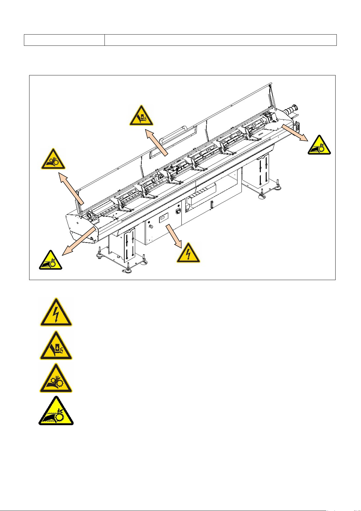
1.2 Warning label
1.2 Warning label
※ :Hazardous voltage. Contact will cause electric shock or burn.
※ :Crush hazard. Keep hands clear of panel clamp system.
※ :Moving parts can crush and cut.
※ :Moving parts can crush and cut.
1-2
1. General information
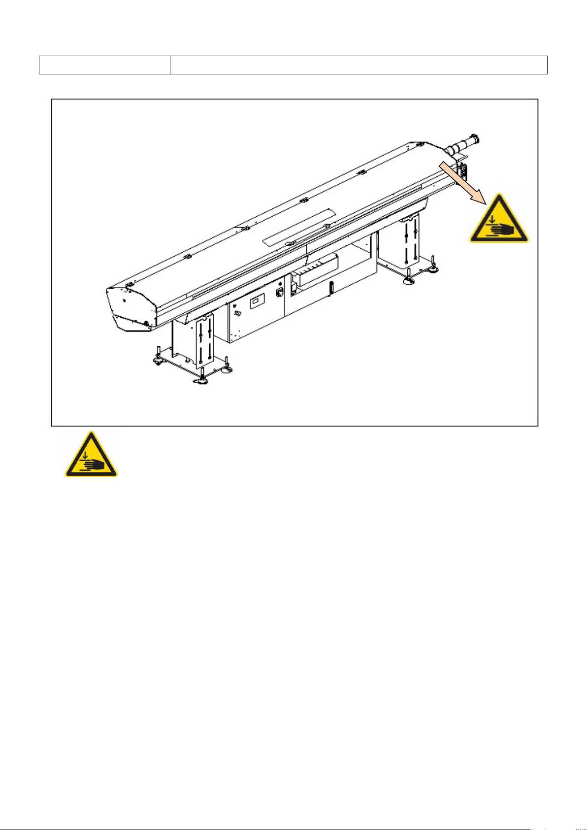
1.2 Warning label
※ :Crush hazard. Keep hands clear of panel clamp system.
1-3

2. Technical data
Chapter first page
2.1 Technical specification…………………………………………………… 2-1
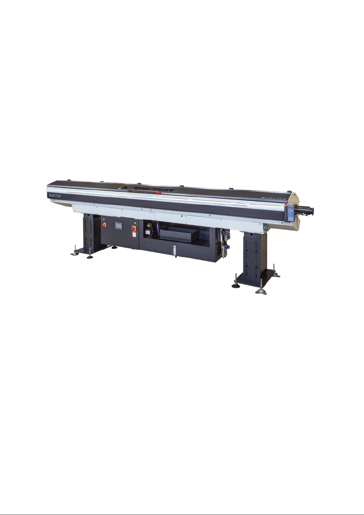
2.1.1 Specification of the appear ance………………………………………… 2-1
2.1.2 Technical specification form ……………………………………..….. 2-1
2.2 Lubricant application ……………………………………………………. 2-2
2.2.1 Hydraulic oil characteristic for guide-channel …......………………….. 2-2
2. Technical data
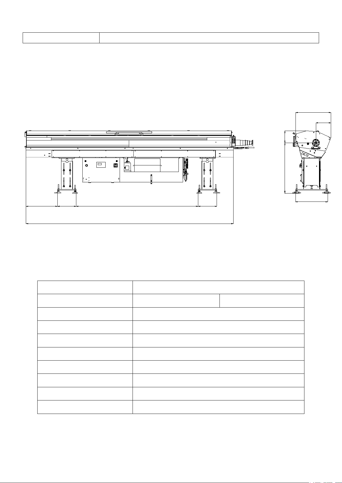
2.1 Technical specification
604 360
2.5M=2264mm
3.0M=2349mm 360
2.5M=3490mm
3.0M=3990mm
288
675
222
900~1300
620
2.1.1 Specification of the appearance
2.1.2 Techni ca l sp e ci f ication form
Project
Round diameter of bar Ø 5min Ø 51max
Largest length of bar 2.5M:2700mm / 3.0M:3200mm
Bar loading capacity
Voltage Input AC 220V 3 Ø
Frequency 50 / 60Hz
Voltage DC24V
Air pressure 6 kgf / cm² 70psi
Bar 10mm(3/8”)× 28 bar
Capacity of the lubricating oil
Net weight ( Do not include the oil )
67L(16.75 gallons)
2.5M:800Kg 3.0M:900Kg
2-1

2. Technical data
2.2 Lubricant application
2.2 Lubricant applica ti on
CAUTION!
Please follow safety regulations while handling oil.
* Clean t ank.
* Pour the hydraulic oil into to the oil tank directly.
2.2.1 Hydraulic oil characteristic for gui de -channel To u se lower viscosity o f
lubricant is advised upon indoor temperature is under 30 degrees in
Celsius.
Hydraulic lubricant stickiness advised are below Quantity
FK ISO VG 68-80
FK HYDRAULIC OIL 68-80
Or the same characteristic hydraulic oil.
* No toluene or corrosive chemistry is used.
67L(16.75 gallons)
67L(16.75 gallons)
2-2

3. Transport and install
Chapter first page
3.1 Packing ……………………………..…………………………………….. 3-1
3.2 Hoisting ………………………………………………………….………… 3-2
3.3 Installation space …………………………………………………….…… 3-3
3.4 Installation……………………………………………………….………… 3-4
3.4.1 Install the support board and foot block………………………………… 3-4
3.4.2 Make a preliminar y alignment ………………………………………….. 3-5
3.4.3 Centering alignment ………………………………..…………………… 3-6
3.4.4 Anchoring bar feeder ………………………….…………………..……… 3-7
3. Transport and install
3.1 Packing
3.1 Packing
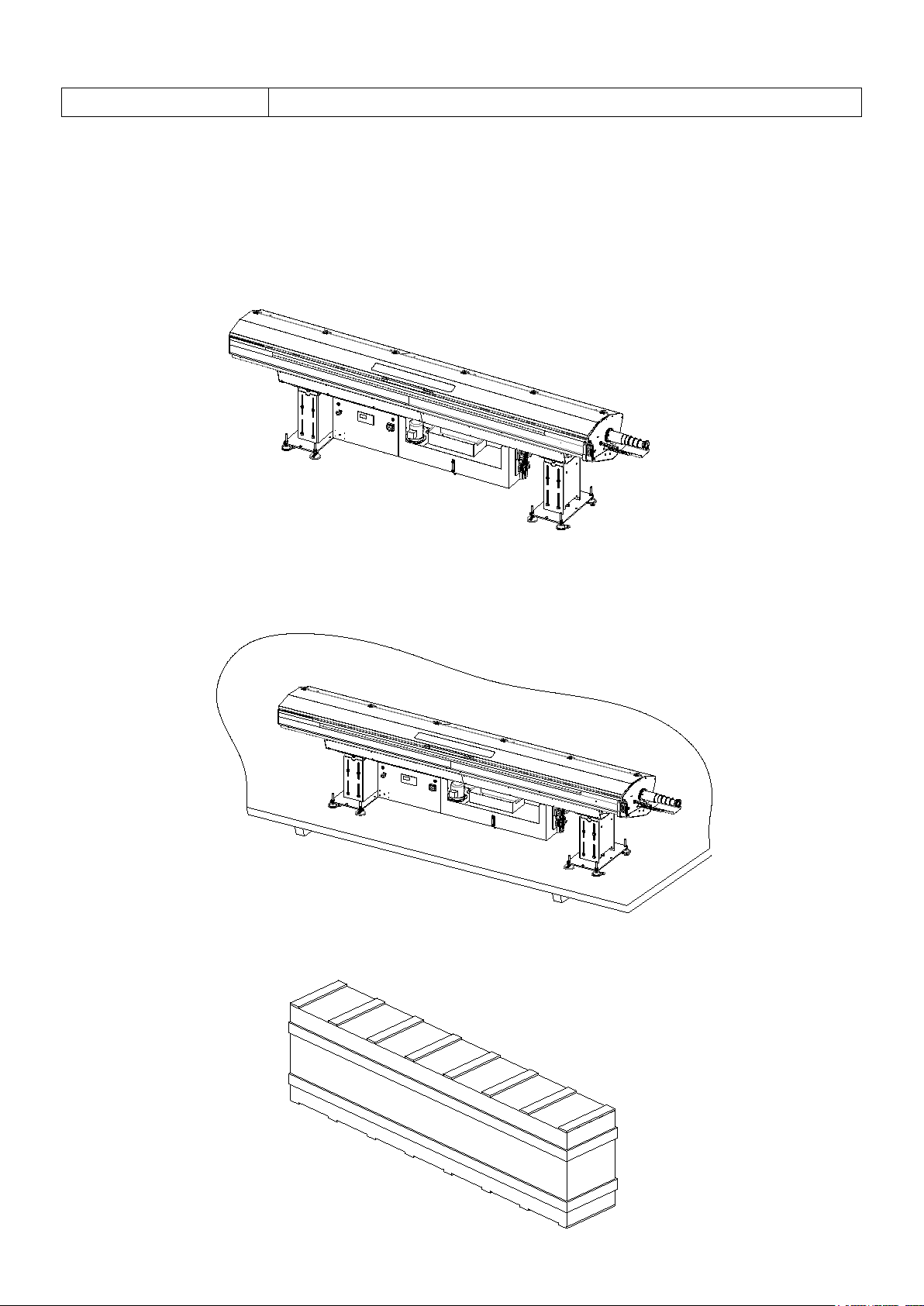
There are three methods of packing the bar feeder:
1. Unpackaged
2. Put it on the skid: Use PE mem brane to cov er and seal.
3. Wooden case:
3-1

3. Transport and install
3.2 Hoisting
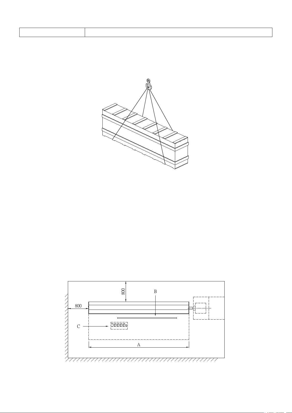
3.2 Hoisting
DANGER-CAUTION
Hoisting should be done by trained personnel using suitable equipment.
The hoisting of bar feeder
See diagram below:
When moving the bar feeder use slings with proper weight ratings.
Put the bar feeder on a skid to hoist and transport. See diagram below.
When moving the bar feeder use slings with proper weight ratings.
3-2
3. Transport and install
3.3 Installation space
Hoisting and transporting the barfeeder in a wooden crate. See diagram below.
When moving the bar feeder use slings with proper weight ratings.
3.3 Installation space
1. The floor must be smooth, solid and convenient to fix to the ground.
2. In common use of the bar feeder reserve the proper area for the bar feeder to operate.
Area: (A- personnel operation space), (B- material area), (C- remnant rejected area). Give ample space
to prevent accidental collision with the bar feeder when the equipment is operating.
3. The installation area must have lighting, a power source plug and compressed air.
4. When the bar feeder is running, it has oil evaporation. Please guarantee the factory is well ventilated.
5. This bar feeder is not suitable for an environment with explosive gas.
3-3
3. Transport and install
3.4 Installation
B
A
B
A
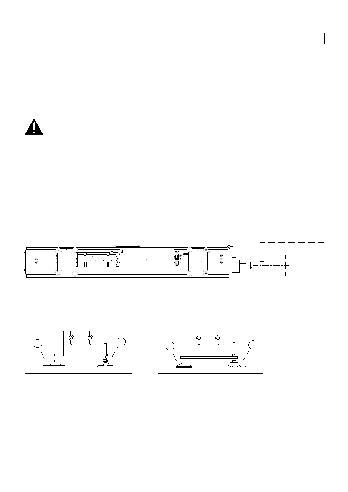
3.4 Installation
Please check stability of the lathe before installing the bar feeder. Confirm that the lathe has been already
fixed to the ground, and the spindle axis is level.
DANGER-CAUTION
Wrong adjustment may cau se damage to the bar feeder.
3.4.1 Install the su pport board and foot block
1. Hang the bar feeder to the spindle height of the lathe.
2. Suspend the bar feeder, in accordance into the foot block (A), and (B).
3-4
3. Transport and install
3.4 Installation
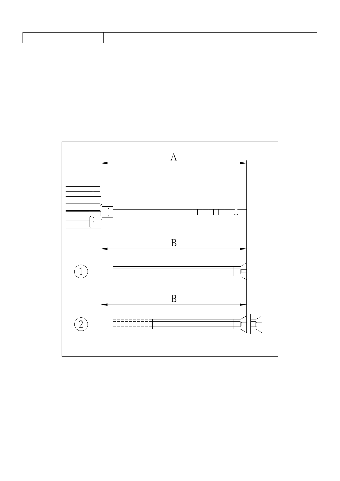
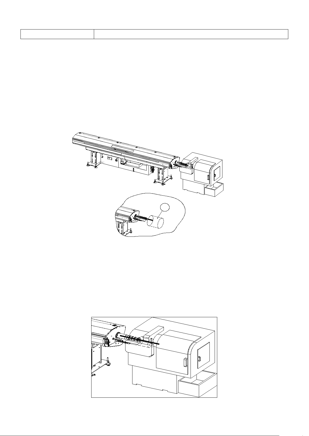
3.4.2 Make a preliminary alignment
Put the bar feeder at the straight rear of the lathe, after calculating both dynamic operation space, the
distance (B)can't be greater than the maximum pusher extension length(A).
1. Fix ty pe lathe traditional camshaft CNC lathe.
2. Sliding headstock type CNC lathe(Swiss type ).
3-5
3. Transport and install
3.4 Installation
D
3.4.3 Centering alignment
1. To get a correct center position, prepare a nylon string, draw from the lathe chuck to the bar feeder
tail , then do the following:
(1) Put – leveling gauge on the lathe collets :
(2) The nylon string is drawn until first feed block centre:
(3) Checking nylon string and spindle ( D ) with calipers , the interval of four directions should maintain
0.15 mm .
2. Place a bar in the guide-channel to level the centre with the following steps:
(1) Prepare a straight and round bar that’s diameter is the maximum guide-channel capacity, the length
equal to double the distance between lathe and bar feeder.
(2) Put and slip the bar in the main spindle through the guide channel set until the bar is nearly at the
lathe collets.
3-6
3. Transport and install
3.4 Installation
B
A
B
A
A
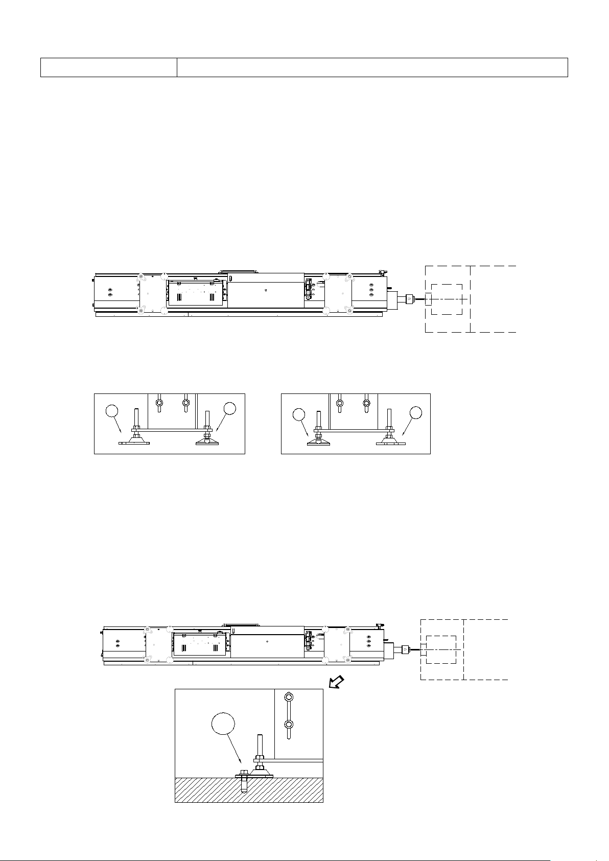
3. Alignment and leveling
(1) Bar feeder leveling adjustment should be done after bar feeder centering by nylon string or the bar
check is completed.
(2) If a height adjustment is needed, rotate the screw in the foot block.
If a lateral adjustment is needed use a wooden hammer to knock the edge of foot block(A).
(3) Pay attention to keeping the level and alignment that has already been finished. Under most
situations a fine adjustment will allow the bar feeder to reach the proper and perfect alignment.
3.4.4 Anchoring the bar feeder
Anchoring the bar feeder
1. Bore holes in the ground. Use the anchor bolts to lock the foot block to the ground.
2. Fix and support the bar feeder on the foot block temporarily, then lock the nut (A).
3. Check the center level once again.
3-7

4. Setting and adjustment
Chapter first page
4.1 Adjustment and setting ………………………………………….…… 4-1
4.2 General adjustment …………………………………………………….. 4-1
4.3 Establish adjustment requirements for bar sizes ……………………. 4-2
4.4 Changing the bar dimension …………………………………………. 4-3
4.5 The guide to adjust the chain tension ………………………………. 4-8

4. Setting and adjustment
4.1 Adjustm ent and setting
4.1 Adjustment and settin g
DANGER-CAUTION
Do not make any adjustments while the bar feeder is in operation unless the manual
specifies to.
This barfeeder needs to be adjusted for different sizes of material. Please reference this manual
to insure the proper parts are installed to match the bar sizes for your process.
4.2 General adjustment
In order to enable the bar feeder to maintain high-efficiency operation make the necessary adjustments
after maintenance or part changes.
4-1

4. Setting and adjustment
4.3 Establish adjustment requirements for bar sizes
4.3 Establish adjustment requirements for bar sizes
Some adjustments may be required when changing bar diameters. Follow this information for
proper operation of the bar feeder. The table below coordinates channel guide, pusher and
material size ranges.
Table 1. Guide-channel, pusher, and bar size reference
Feeding capacity
Guide-channel size
(mm)
Pusher size
(mm)
(mm)
Min Max
21 20 5 20
27 26 5 26
33 32 5 32
37 36 5 36
39 38 5 38
43 42 5 42
46 45 5 45
52 51 5 51
4-2
4.
Setting and adjustment
4.4 Process of changing the bar size
bar diameter scale.
smaller bar diameter scale.
4.4 Process of Changing the bar dimension
This chapter provides the operator details to change bar sizes. Please refer to the following
pictures.
(1) Changing the pusher collet.
(2) Pre-adjust to flatten bar magazine (active holders are adjustable).
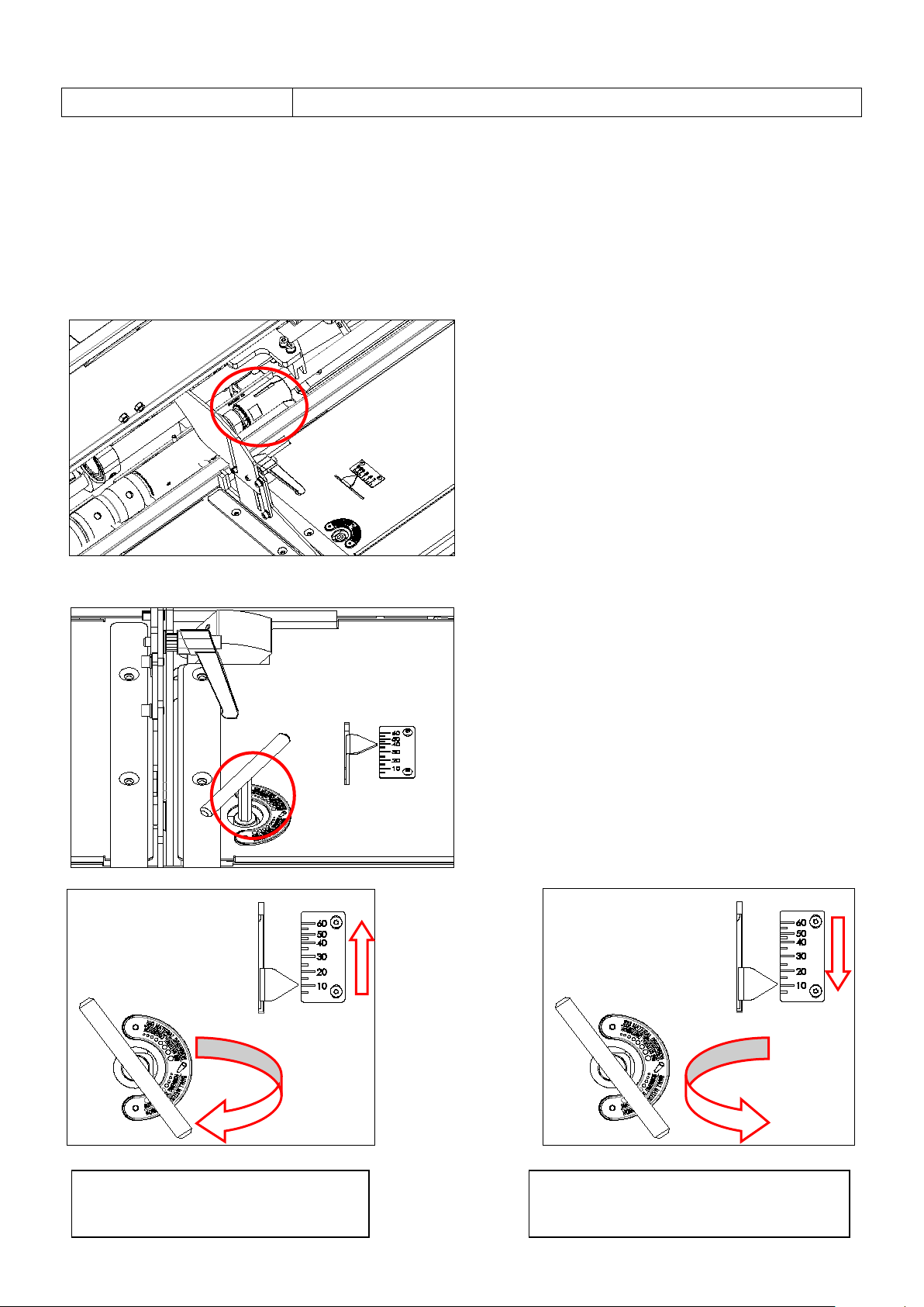
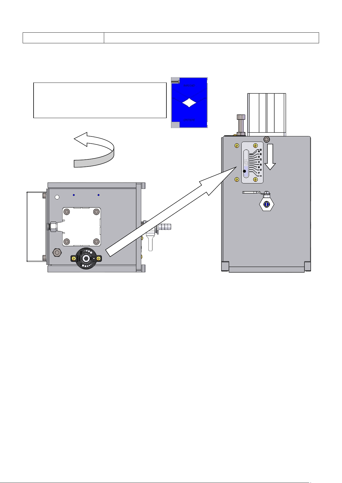
Adjust clockwise means bigger
Adjust counterclockwise means
4-3
4.
Setting and adjustment
4.4 Process of changing the bar size
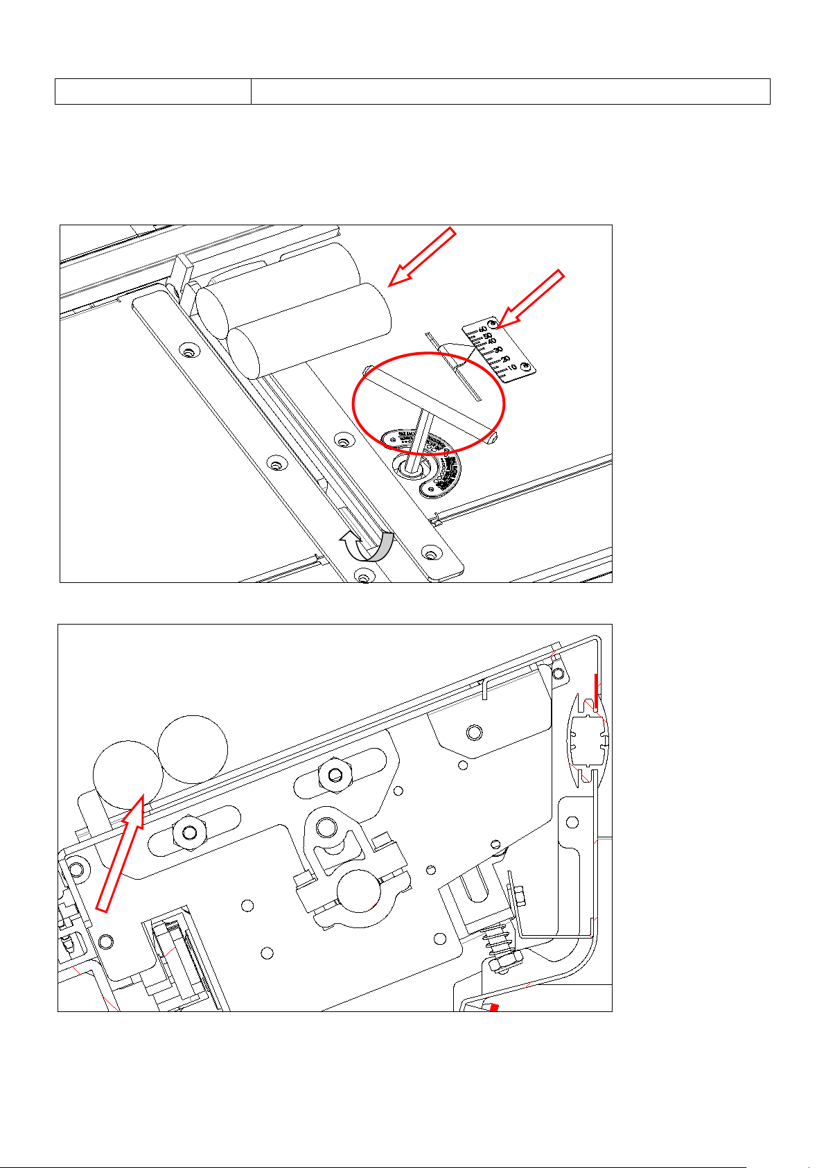
4.4.1 As shown in the figure: When processing a bar with a diameter of 10mm, insert the 8#
wrench into the screw hole of the bar siz e, rotate counterclockwise, and point the pointer to the
position of 10 to confirm that one material can be lifted, and two cannot be ejected at the same
time.
4-4
4.
Setting and adjustment
4.4 Process of changing the bar size
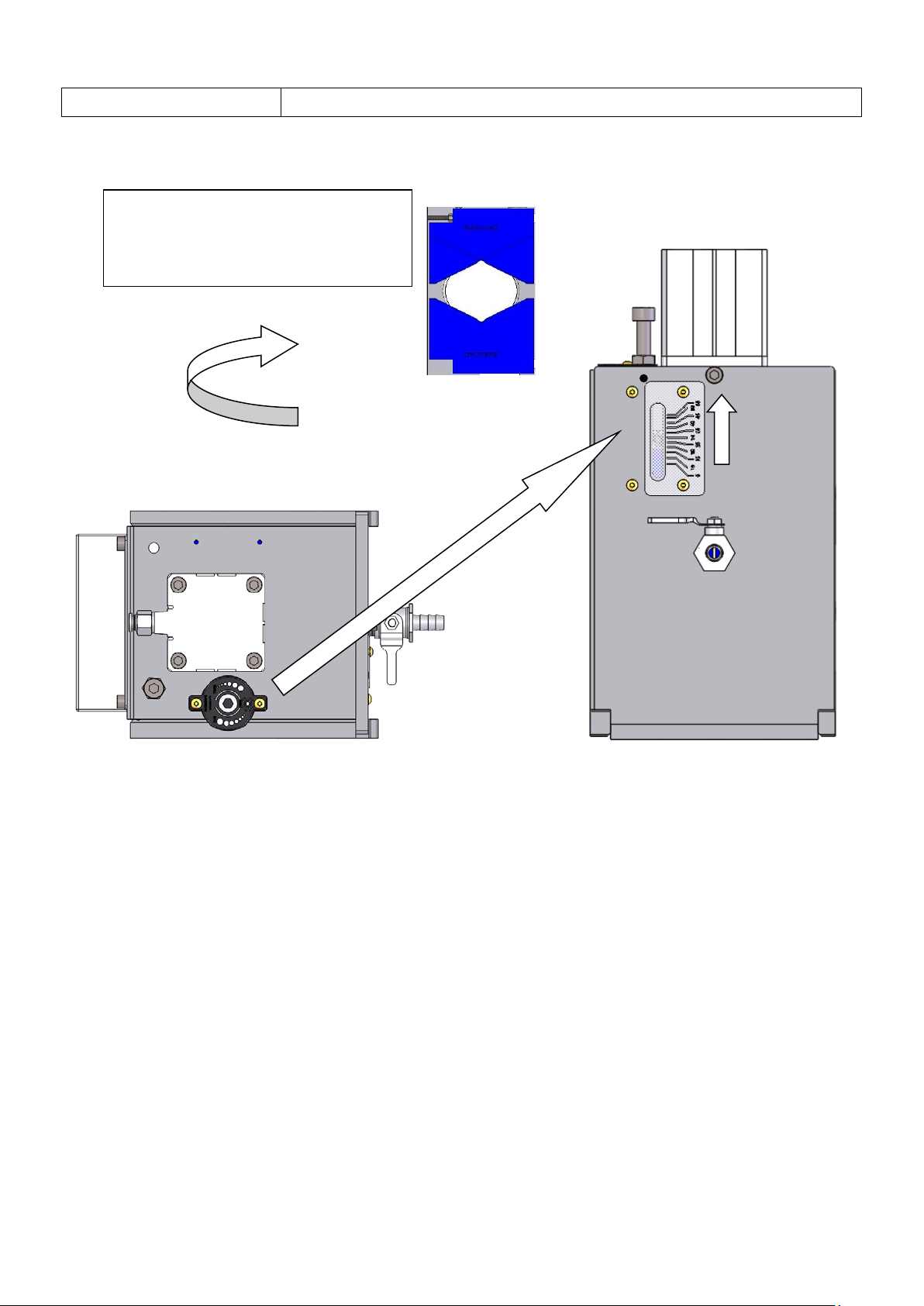
4.4.2 As shown in the figure: When processing a bar with a diameter of 40mm, insert the 8#
wrench into the scr ew hole of the bar s ize, rot ate cl ockwi se, and poi nt the p oint er to the posi tion of
40 to confirm that one material can be lifted, not two at the same time.
4-5
4.
Setting and adjustment
4.4 Process of changing the bar size
Adjust counterclockwise, the smaller the
gap between the shockproof rubber
blocks.
(3)Adjusting or changing the anti-vibration device :
4-6
4.
Setting and adjustment
4.4 Process of changing the bar size
Adjust clockwise, the larger the gap
between the shockproof rubber
blocks.
Go set parameters following anti-vibration device adjustment and (or) the right size
of front bush interchange.
(4) Parameter Setting ( too long/ too short values on workpiece length).
(5) Change the lathe parameter and program for new bar processing.
(6) Starts the automatic operation.
4-7
4. Setting and adjustment
4.5 Adjust the belt tightness of the servo motor group and the tightening of
the drive chain
4.5 Adjust the belt tightness of the ser vo mo tor group and the tightening of
the drive chain
1. Servo motor group belt tightening adjustment
①. With a 10-gauge open-end wrench, loosen the M6 hex screw counter cl oc kw i se, and then lock
the screw clockwise after debugging OK.
4-8
4. Setting and adjustment
4.5 Adjust the belt tightness of the servo motor group and the tightening of
the drive chain
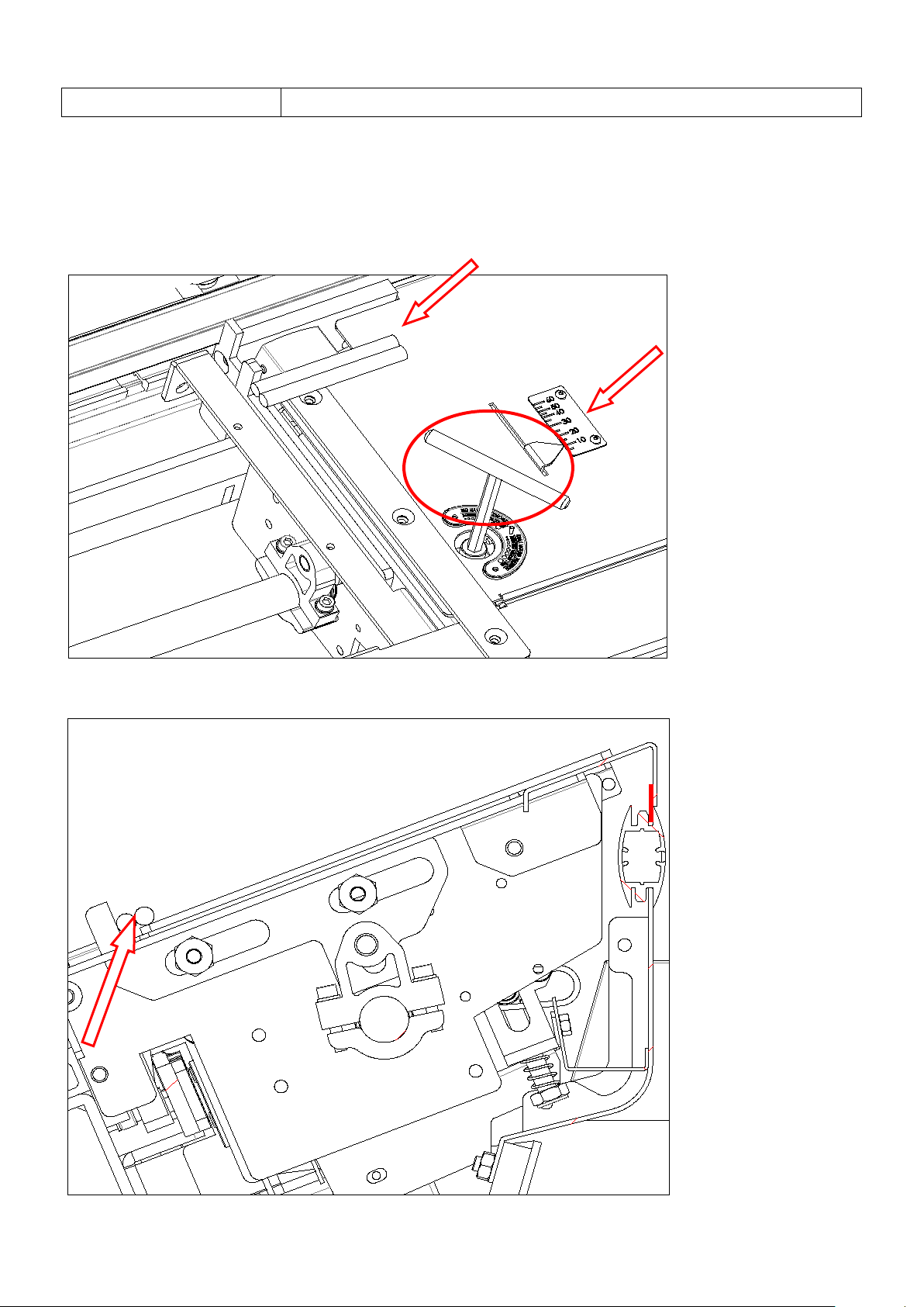
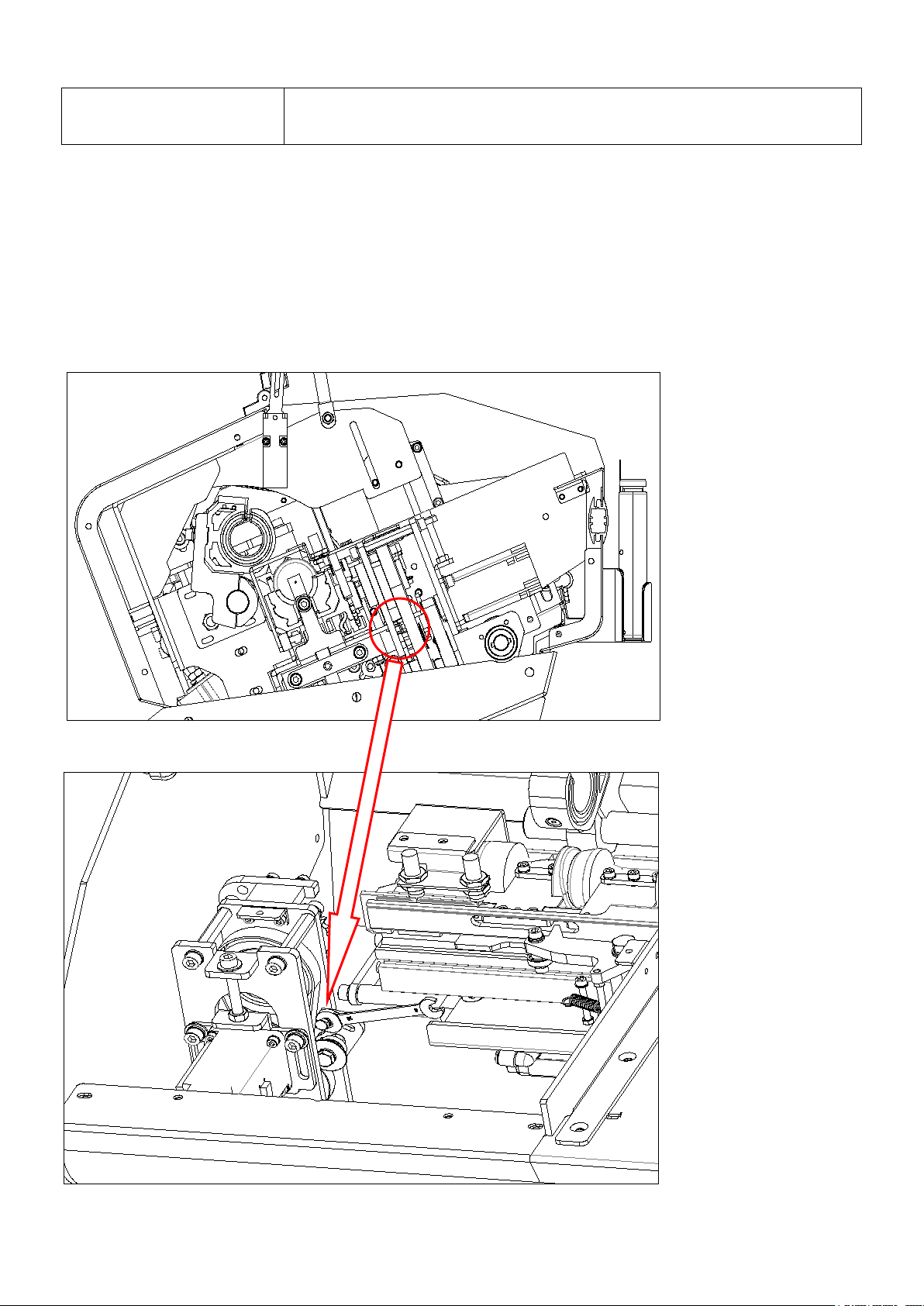
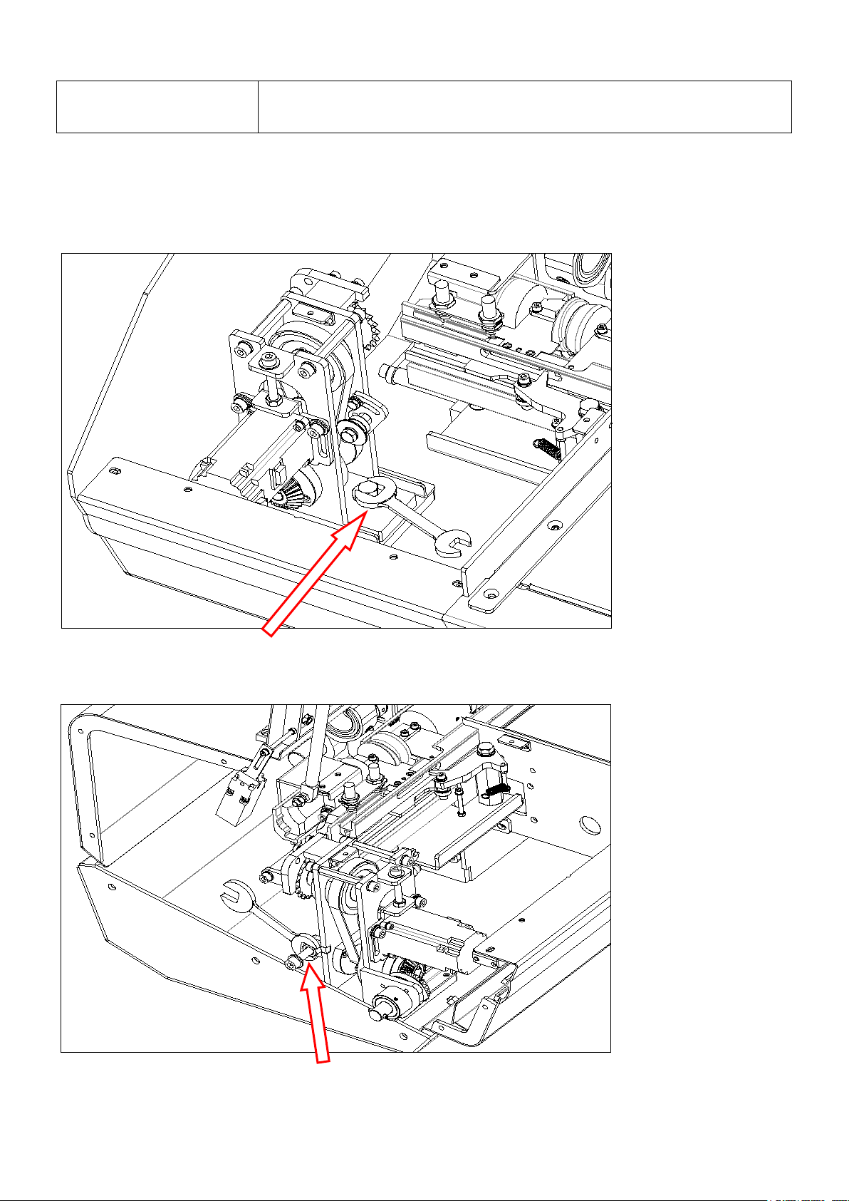
2. Transmission chain tightness adjustment
①. Use a 17-gauge cotter wrench to loosen the M10 hex screw counterclockwise.
②. Then use a 17-gauge open-end wrench to release the M10 nut counterclockwise.
4-9
4. Setting and adjustment
4.5 Adjust the belt tightness of the servo motor group and the tightening of
the drive chain
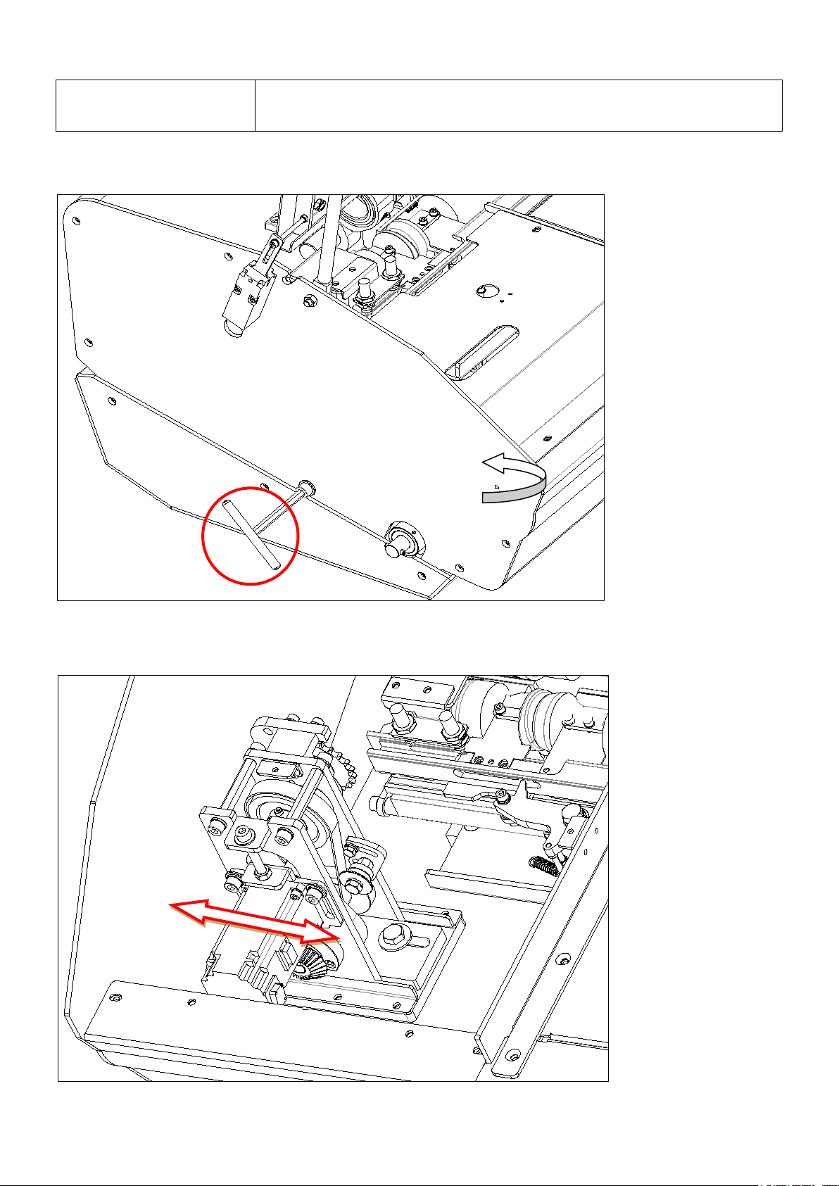
③. Then use an No. 8 T-wrench to loosen the M10 Allen screw counterclockwise.
④. Pan the servo motor group and adjust the chain to the appropriate tightness.
4-10
4. Setting and adjustment
4.5 Adjust the belt tightness of the servo motor group and the tightening of
the drive chain
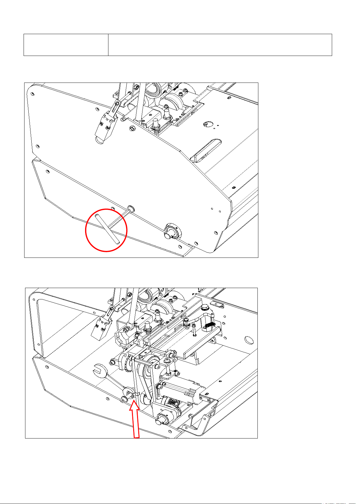
⑤.After debugging OK, use the No. 8 T-wrench to lock the M10 Allen screw clockwise.
⑥. Then use a 17-gauge open-end wrench to lock the M10 nut clockwise.
4-11

4. Setting and adjustment
4.5 Adjust the belt tightness of the servo motor group and the tightening of
the drive chain
⑦. Finally, use a 17-gauge open-end wrench to lock the M10 Allen screw clockwise.
4-12

5. Operation
Chapter first page
5.1 Characteristic and preparation ……………………………………….… 5-1
5.2 Emergency stop …………………………………………………………. 5-2
5.3 The alarm message and reset …………………………………………. 5-2
 Loading...