

Page 1

Installation
Instructions
Advantium® 120V
Built-In SpeedCook
and 120V Built-In
Convection Ovens
CSB9120
PSB9120
ZSC1201
ZSC1202
CWB7030
PWB7030
CWB713
31-2000001-5
01-19 GEA
Español
For a Spanish version of this manual, visit
our Website at GEAppliances.com.
Para consultar una version en español de
este manual de instrucciones, visite nuestro
sitio de internet GEAppliances.com.
GE is a trademark of the General Electric Company. Manufactured under trademark license.
Page 2
Safety Information
BEFORE YOU BEGIN
Read these instructions completely and
carefully.
IMPORTANT
for local inspector’s use.
IMPORTANT
and ordinances.
• Note to Installer — Be sure to leave these
instructions with the Consumer.
• Note to Consumer — Keep these instructions
with your Owner’s Manual for future reference.
• Skill Level — Installation of this appliance
requires basic mechanical and electrical skills.
• Completion Time — 1 Hour.
• Proper installation is the responsibility
of the installer. Product failure due to improper
installation is not covered under the warranty.
See Owner’s Manual for warranty information.
NOTE: This oven is only approved to be installed
under the specific models as labeled on this unit.
IMPORTANT
intended purpose. Never use the oven for
warming or heating a room. Prolonged use
of the oven without proper ventilation can be
hazardous.
CAUTION
house fuse or oven circuit breaker before
beginning installation to avoid severe or fatal
shock injury.
CAUTION
mounting surface must be capable of supporting
the cabinet load, in addition to the added weight
of the oven and drawer, plus additional oven
loads.
CAUTION
Convection 120V Oven below 36Ǝ, you must
use the plastic bottom trim due to burn risk
to children. The plastic trim acts as insulation
and will help prevent burns to children from hot
surfaces.
CAUTION
Convection 120V Oven below 36Ǝ, do not
remove the plastic door trim due to burn risk
to children. The plastic trim acts as insulation
and will help prevent burns to children from hot
surfaces.
—
Save these instructions
—
Observe all governing codes
—
Use this oven only for its
For personal safety, remove
For personal safety, the
If installing the Advantium/
If installing the Advantium/
CONTENTS
Design Information
Models Available ...............................................2
Product Dimensions and Clearances ................3
Tools Required .................................................. 3
Parts Supplied ................................................... 3
Advance Planning ............................................. 3
Installation Preparation
Electrical Requirements .................................... 4
Preparing the Opening (Standard) .................5-8
Preparing the Opening (Flush Mount) ..........9-10
Storage Drawer Preparation
Standard .........................................................11
Flush ...............................................................11
Installation Instructions
Step 1, Remove Packaging and Parts ............12
Step 2, Door Trim Removal for above 36”
Installation only ...............................................13
Step 3, Slide the Oven into the Cutout ...........13
Step 4, Install Bottom Trim ..............................14
Step 5, Install Bottom Trim with Accessory
Drawer ...........................................................14
Step 6, Install Mounting Screws ......................14
Step 7, Finalize Installation .............................14
MODELS AVAILABLE
Profile Models:
PSB9120WW – White*
PSB9120BB – Black
PSB9120SS – Stainless Steel
PSB9120ES – Slate
PWB7030SL – Stainless Steel
PWB7030EL – Slate
PSB9120BL – Black Stainless Steel
Monogram Models:
ZSC1201SS – Stainless Steel
ZSC1202SS
Café Model:
CSB9120SS – Stainless Steel
CWB7030SL – Stainless Steel
*No color-matched drawer available for this
model.
**This unit cannot be installed with an
accessory storage drawer.
– Stainless Steel**
2
Page 3
Design Information
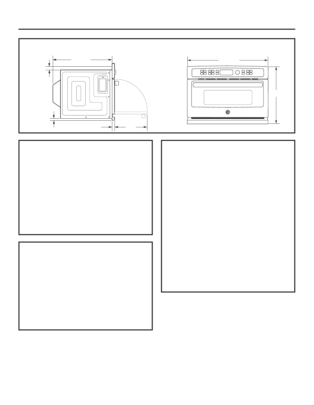
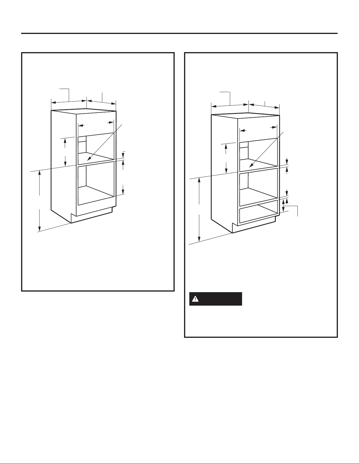
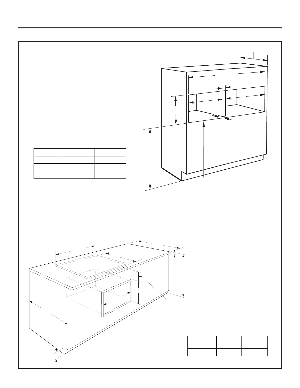
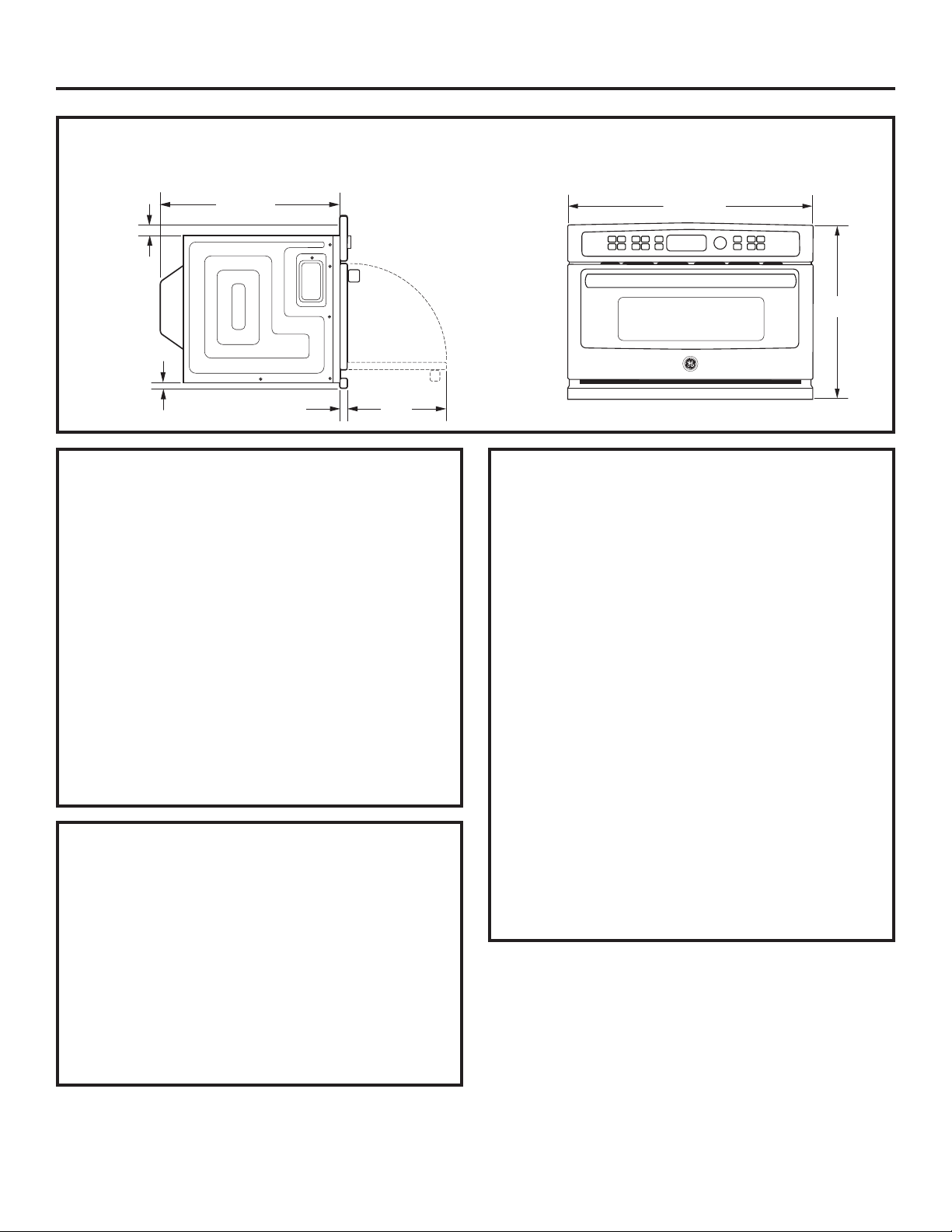
PRODUCT DIMENSIONS AND CLEARANCES NOTE: Appearance will vary by model.
21-1/2Ǝ
1-3/5Ǝ
1Ǝ
1-1/10Ǝ
13Ǝ
TOOLS AND PARTS REQUIRED
(NOT SUPPLIED)
• #2 Phillips screwdriver
Hand-held drill
•
High speed drill bit, 3/32Ǝ diameter
•
3/8Ǝ slot-head screwdriver
•
Level
•
Saw
•
3/8Ǝ min. plywood for floor (if required)
•
Wood screws or other hardware for installing
•
runner or shelf to support oven (if required)
•
Safety glasses or goggles
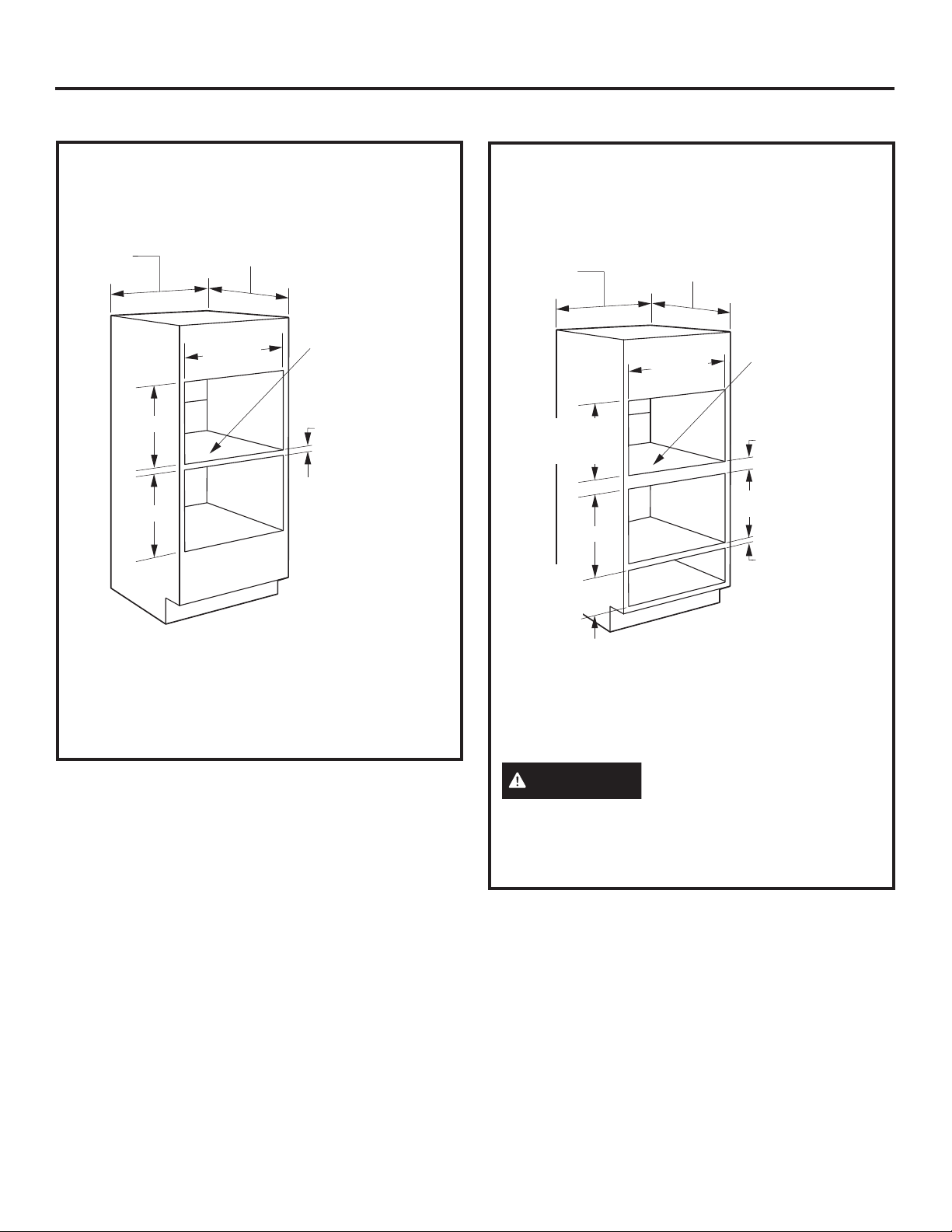
FLUSH MOUNT INSTALLATION
(Monogram Only)
This installation method allows for the unit face to
be inline with the cabinet face.
IMPORTANT: HIGH SKILL LEVEL IN
CARPENTRY IS REQUIRED. Non-standard
cabinetry may be required.
Flush installation of the oven will lead to the
exposure of the cabinet face frame edges.
Side cleats may be visible and should be a
finished surface.
29-3/4Ǝ
19Ǝ
ADVANCE PLANNING
•7KHVHRYHQVPD\EHLQVWDOOHGGLUHFWO\LQWRDƎ
wide oven cabinet with standard installation.
• Cutout height dimensions are different for
installations with an accessory storage drawer.
Make sure to use the correct cutout when
preparing the opening.
• Allow for clearance to adjacent corners, walls,
drawers, etc.
• Cabinets installed adjacent to wall ovens
must have an adhesion spec of at least 194ºF
temperature rating.
The oven must be securely installed in a cabinet
that is firmly attached to the house structure.
Weight on the oven door could cause the oven
to tip and result in injury. Never allow anyone to
climb, sit, stand or hang on the oven door.
If installing the drawer accessory, the drawer
must be assembled to the oven prior to
installation into the cabinet. See the Accessory
Storage Drawer Assembly Instructions.
3
Page 4
Installation Preparation
ELECTRICAL REQUIREMENTS
Single Advantium/Convection 120
Installation:
This product requires a 120-volt, 60 Hz, 15-amp
circuit and draws 1.8 kilowatts. This product must
be connected to a supply circuit of the proper
voltage and frequency.
• Wire size must conform to the requirements of
the National Electrical Code or the prevailing local
code for this kilowatt rating.
• The power supply cord and plug should be
brought to a separate 15 or 20 ampere branch
circuit single grounded receptacle. The outlet box
should be located within reach of the 48” power
cord.
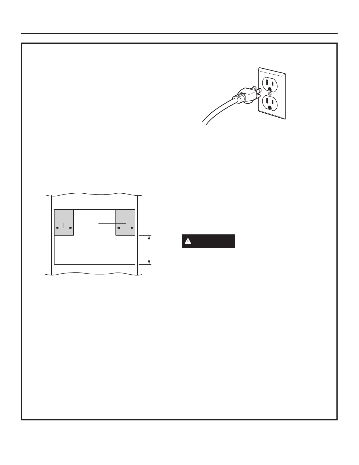
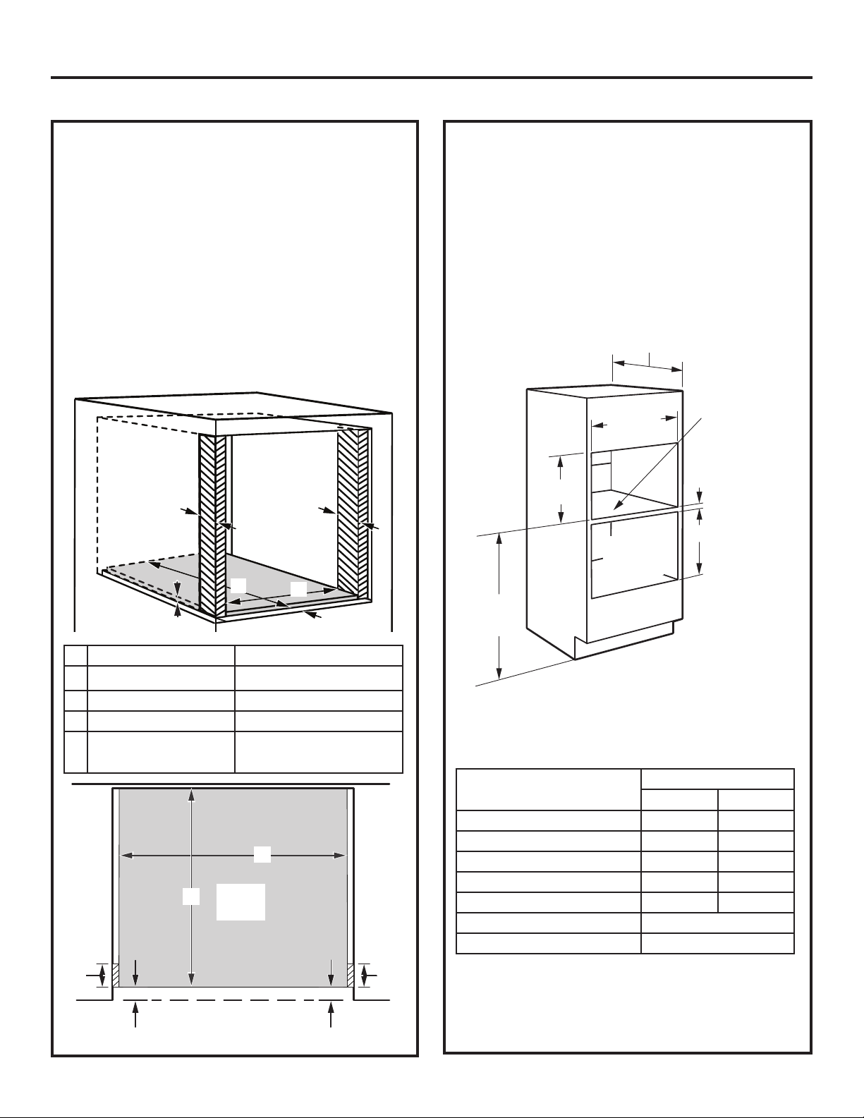
ELECTRICAL LOCATION
6”
GROUNDING
INSTRUCTIONS
This appliance must be grounded. In the event of
an electrical short circuit, grounding reduces the
risk of electric shock by providing an escape wire
for electric current. This appliance is equipped
with a cord having a grounding wire with a
grounding plug. The plug must be plugged into
an outlet that is properly installed and grounded.
9”
Locate outlet box in the shaded area
Install a recessed electrical outlet in the back
wall of the opening within 6Ǝ of either side and
at least 9Ǝ above the cutout floor.
WARNING
Improper use of the
grounding plug can result in a risk of
electric shock.
IMPORTANT: (Please read carefully).
The power cord of this appliance is equipped with
a three-prong (grounding) plug that mates with a
standard three-prong grounding wall receptacle
to minimize the possibility of electric shock.
Consult a qualified electrician or serviceman if
the grounding instructions are not completely
understood, or if doubt exists as to whether the
appliance is properly grounded.
• Where a standard two-prong wall receptacle is
encountered, it is the personal responsibility and
obligation of the consumer to have it replaced with
a properly grounded three-prong wall receptacle.
Do not, under any circumstances, cut or remove
the third (ground) prong from the power cord.
DO NOT USE AN EXTENSION CORD. If the
power supply cord is too short, have a qualified
electrician or serviceman install an outlet near the
appliance.
4
Page 5
Standard Installation Preparation
IMPORTANT: Always maintain 36-3/4” minimum height from the floor to the cutout in any single or
combined installation unless plastic trim is installed.
PREPARE THE OPENING
The Advantium/Convection 120 can be installed
in combination with other GE Appliances/
Monogram appliances. Always follow each
product’s Installation Instructions to complete the
installation.
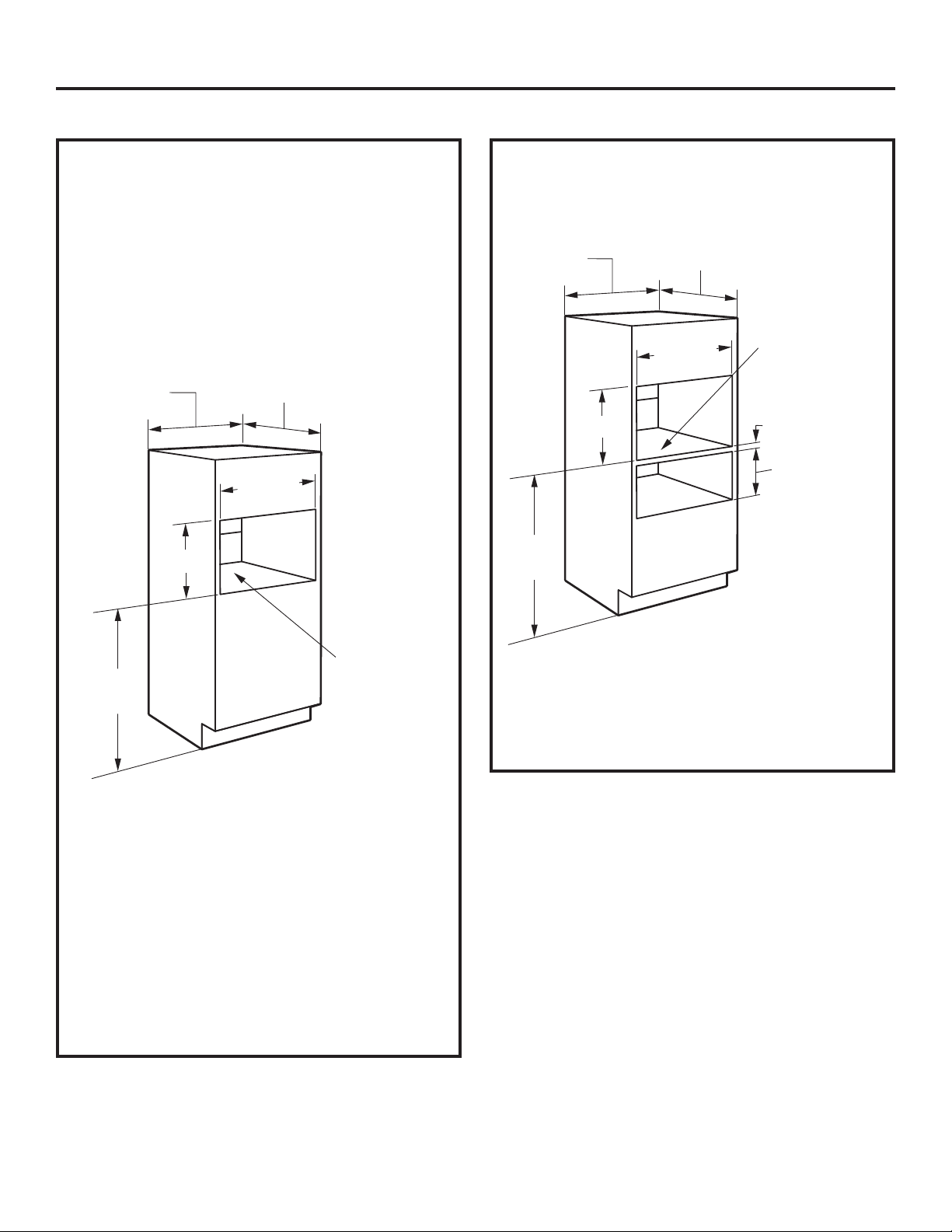
Single Advantium/Convection 120
Installation:
Order a 30” wide single oven cabinet or cut the
opening in a wall to the dimensions shown.
30”
17-1/2”
36-3/4”
Min.
23-1/2”
25-1/4”
Construct
solid bottom
- Min. 3/8”
plywood
supported
on all four
sides. Must
be able to
support
weight of
oven and
contents.
PREPARE THE OPENING (CONT.)
Installation over a GE Appliances/
Monogram Warming Drawer:
30”
17-1/2”
36-3/4”
Min.
NOTE: Additional clearances between the cutouts
may be required. Check to be sure the oven
supports above the Warming Drawer location does
not obstruct the required interior depth and height.
See Warming Drawer installation instructions for
details.
23-1/2”
25-1/4”
Construct
solid bottom
- Min. 3/8”
plywood
supported
on all four
sides. Must be
able to support
weight of oven
and contents.
2” Min.
(3” Recommended)
Per Warming
Drawer
Requirement
Allow 1-1/4” case trim overlap
•
at the top and 7/8” overlap on the bottom and
2-1/4” overlap for each side of the opening.
•
Oven overlaps will conceal cut edges on all
sides of the opening.
When installed over a single oven or a
warming drawer, allow at least 2” between
the two openings. This separation will provide
clearance for bottom overlap of the Advantium/
Convection 120 and the other appliance
overlaps.
•
The support must be level and rigidly mounted,
flush with the bottom edge of the cutout.
5
Page 6
Standard Installation Preparation
IMPORTANT: Always maintain 36-3/4” minimum height from the floor to the cutout in any single or
combined installation unless plastic trim is installed.
PREPARE THE OPENING (CONT.)
Installation over a GE Applainces/
Monogram Oven:
30”
17-1/2”
45-1/4”
Min.
* If you are replacing a GE Appliances/
Monogram electric double oven with the
combined installation of an Advantium/
Convection 120 and a single oven, use the
dimensions shown. The middle rail separating
the two openings may need to be larger than
the 2” minimum shown.
23-1/2”
25-1/4”
Construct
solid bottom
- Min. 3/8”
plywood
supported
on all four sides.
Must be able to
support weight
of oven and
contents.
2” Min.
(3” Recommended)
Per Oven
Requirement
PREPARE THE OPENING (CONT.)
Installation over a GE Appliances/
Monogram Oven and Warming Drawer:
30”
23-1/2”
25-1/4”
17-1/2”
45-1/4”
NOTE: Additional clearances between the
cutouts may be required. Check to be sure
the oven supports above the Warming Drawer
location does not obstruct the required interior
depth and height. See Warming Drawer
installation instructions for details.
Construct
solid bottom Min. 3/8” plywood
supported
on all four sides.
Must be able to
support weight
of oven and
contents.
2” Min.
(3” Recommended)
Per Oven
Requirement
2” Min.
(3” Recommended)
Per Warming
Drawer
Requirement
CAUTION
For personal safety, the
mounting surface must be capable of supporting
the cabinet load, in addition to the added weight
of the oven and drawer, plus additional oven
loads.
6
Page 7
Standard Installation Preparation
IMPORTANT: Always maintain 36-3/4” minimum height from the floor to the cutout in any single or
combined installation unless plastic trim is installed.
PREPARE THE OPENING (cont.)
Installation over another GE Appliances/
Monogram Built-In SpeedCook Oven:
30Ǝ
17-1/2Ǝ
17-1/2Ǝ
23-1/2Ǝ
25-1/4Ǝ
Construct
solid bottom - Min.
3/8” plywood
supported
on all four sides.
Must be able to
support weight
of oven and
contents.
2Ǝ Min.
(3Ǝ Recommended)
PREPARE THE OPENING (cont.)
Installation under a GE Appliances/
Monogram Microwave Oven and over a
Warming Drawer:
Construct
30Ǝ
Per Microwave
Oven Requirement
17-1/2Ǝ
Per Warming
Drawer
Requirement
23-1/2Ǝ
25-1/4Ǝ
solid bottom - Min.
3/8” plywood
supported
on all four sides.
Must be able to
support weight
of oven and
contents.
3.5Ǝ Min.
(4.5Ǝ Recommended)
2Ǝ Min.
(3Ǝ Recommended)
•
If you are mounting a GE Appliances
Appliances/Monogram Built-In
Oven over another, use the dimensions
SpeedCook
shown.
The middle rail separating the two openings
may need to be larger than the 2Ǝ minimum
shown.
NOTE: Additional clearances between the
cutouts may be required. Check to be sure
the oven supports above the Warming Drawer
location do not obstruct the required interior
depth and height. See Warming Drawer
installation instructions for details.
CAUTION
For personal safety, the
mounting surface must be capable of supporting
the cabinet load, in addition to the added weight
of the oven and drawer, plus additional oven
loads.
7
Page 8
Standard Installation Preparation
IMPORTANT: Always maintain 36-3/4” minimum height from the floor to the cutout in any single or
combined installation unless plastic trim is installed.
PREPARE THE OPENING (cont.)
Installation beside another GE
Appliances/Monogram Built-in
Speedcook Oven:
• If you are mounting a GE Appliances/
Monogram Built-In
another, use the dimensions shown. The
middle rail separating the two openings may
need to be larger than the 4-1/2Ǝ minimum
shown.
SpeedCook Oven
beside
PREPARE THE OPENING (cont.)
17-1/2Ǝ
25-1/4Ǝ
23-1/2Ǝ
25-1/4Ǝ
17-1/2Ǝ
4-1/2Ǝ Min.
(5-1/2Ǝ Recommended)
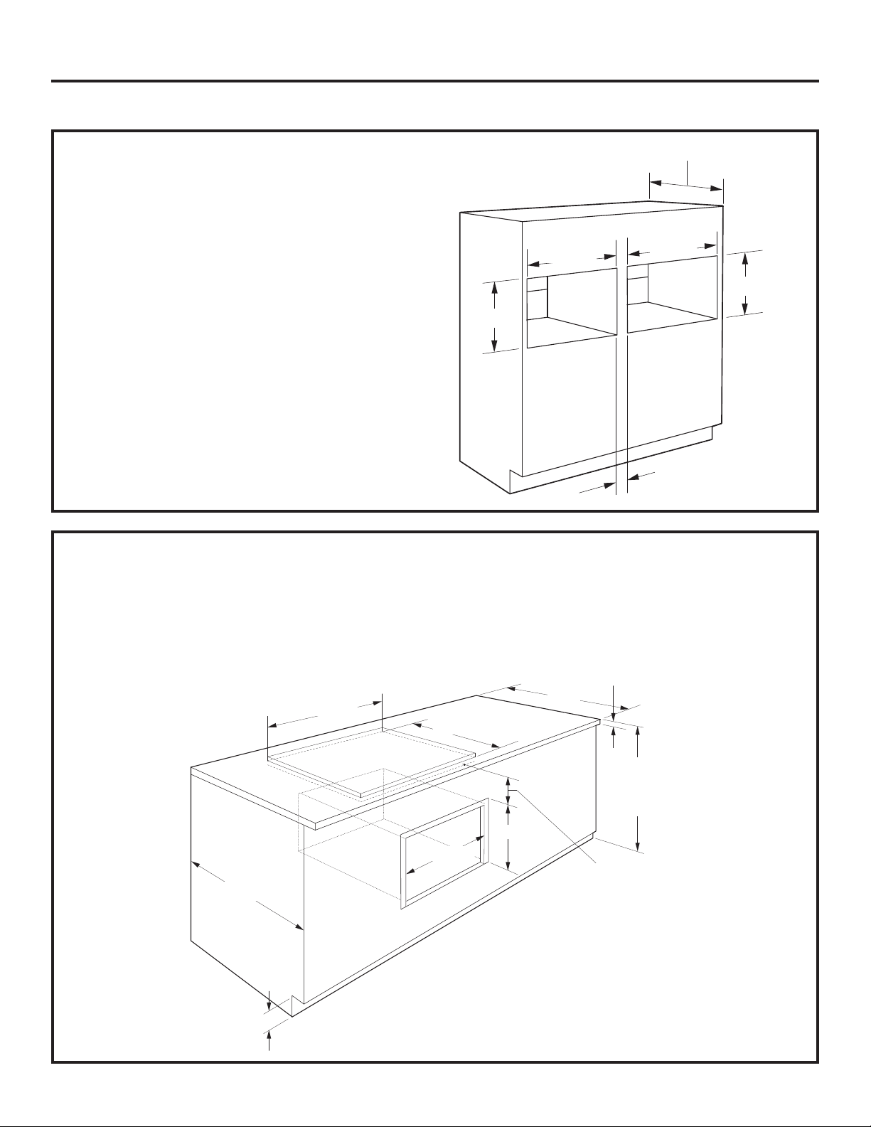
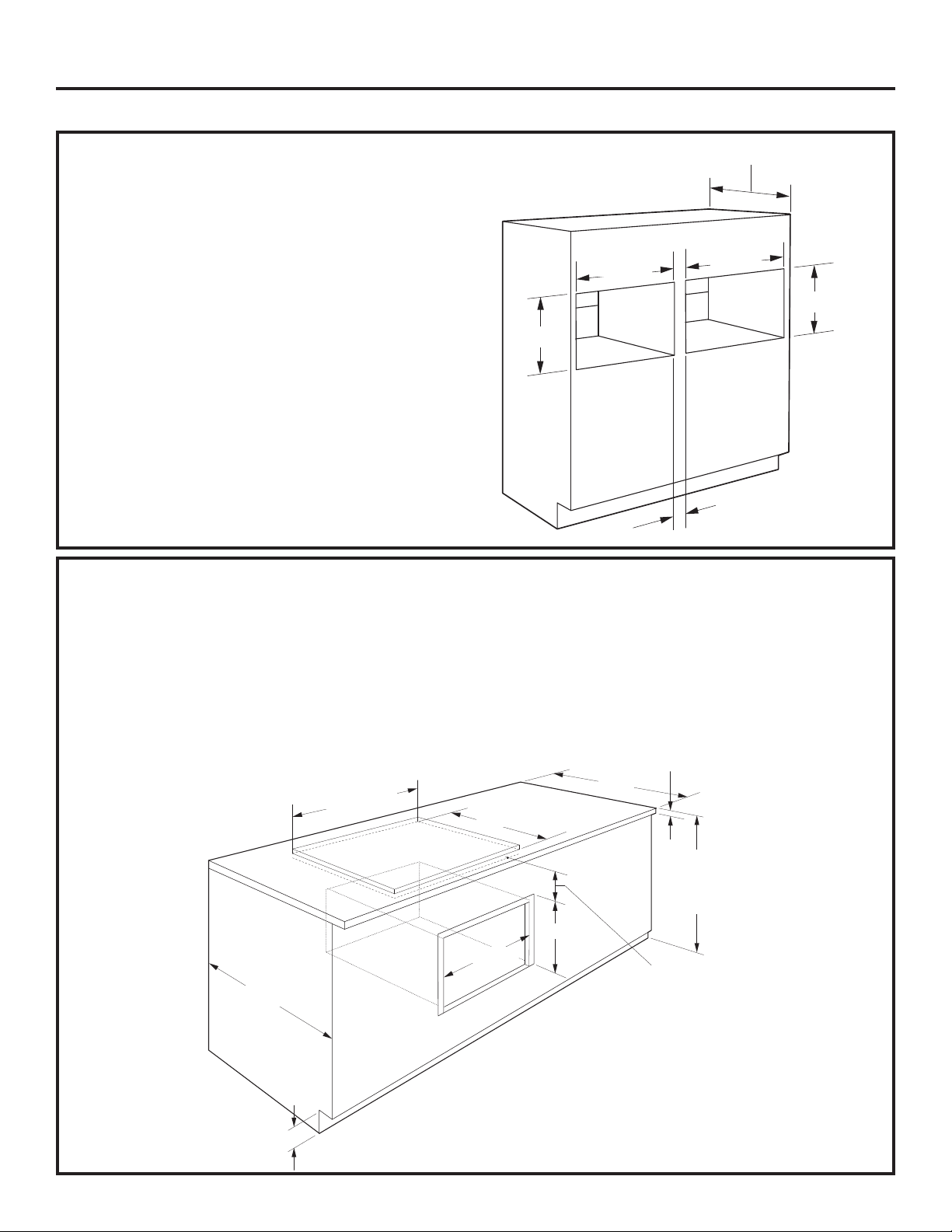
Installation under a GE Appliances/Monogram 30Ǝ or 36Ǝ Cooktop or Countertop:
Gas or electric cooktops may be installed over this oven. See cooktop installation instructions for the
cutout size. See the label on top of the oven for approved cooktop models. This oven requires a separate,
properly grounded 15-Amp, 120-Volt, 60Hz power supply. The cooktop requires a separate power supply.
Use a 36Ǝ or wider base cabinet.
1-1/2Ǝ Min.
25Ǝ
36Ǝ
Countertop
Height
Ǝ
Cooktop height including depth
of electrical box on some
models. Refer to cooktop
installation instructions.
No minimum clearance required
between cooktop and oven.
23-1/2
4Ǝ High
Toekick
Cooktop
Cooktop
17-1/2
25-1/4Ǝ
Ǝ
NOTE: The oven is only approved to be installed
under the specific models as labeled on the unit.
8
Page 9
Flush Mount Installation Preparation (Monogram Only)
IMPORTANT: Always maintain 36-3/4” minimum height from the floor to the cutout in any single or
combined installation unless plastic trim is installed.
PREPARE THE INTERIOR
Cut and install side cleats:
• Cut side wood cleats to height of cabinet
opening and approx. 2-1/2” in depth. Install,
on each side, 1-3/8” from the front face of the
cabinet.
Cut and install bottom cleat:
• Cut bottom wood cleat to a height of 1-1/8”, a
depth of the cabinet minus 1-3/8” and a width
of 25-1/4” to fit between side cleats. Install
onto the cabinet floor between the side cleats,
push it all the way back against cabinet wall
and make sure its front face aligns with the front
faces of the side cleats (1-3/8” gap from the
front cabinet face).
A A
C
B
D
E
PREPARE THE OPENING
The Advantium 120 can be installed in
combination with other GE Appliances/
Monogram appliances. Always follow each
product’s Installation Instructions to complete the
installation.
Single Advantium 120 Installation:
Cut the opening in a cabinet to the dimensions
shown.
*See table
below for
desired reveals
on sides.
**19-1/4”
36-3/4”
Min.
23-1/2” min.
F *
Oven or
warming
drawer
Construct
solid bottom
- Min. 3/8”
plywood
supported on
all four sides.
Must be able to
support weight
of oven and
contents.
2” Min.
Per
appliance
specs.
A Side cleats depth 2-1/2” min.
B Bottom cleat height 1-1/8”
C Bottom cleat depth Cabinet depth minus 1-3/8”
D Bottom cleat width 25-1/4”
E All three cleats Recess and install 1-3/8”
IURPGHVLUHGÀXVKVXUIDFH
D
TOP
C
VIEW
A A
Front Face of Cabinet
EE
• The support must be level and rigidly mounted,
flush with the bottom edge of the cutout.
Approved Flush Installation
Single Advantium 30” 30-1/4”
Over Warming Drawer 30” 30Over Oven
Over Oven and Warming Drawer
Over Built-in Speedcook Oven
Double Advantium (side by side)
Under Cooktop or Countertop See page 10
Dimension F
1/8” Reveal 1/4” Reveal
1
/4”
30” 30-1/4”
30” 30-1/4”
30” 30-1/4”
See page 10
** Top and bottom reveals are set to 1/8”.
9
Page 10
Flush Mount Installation Preparation (Monogram Only)
IMPORTANT: Always maintain 36-3/4” minimum height from the floor to the cutout in any single or
combined installation unless plastic trim is installed.
PREPARE THE OPENING
The Advantium/Convection 120 can be installed beside
another Advantium/Convection 120 in a side-by-side
combination.
Double Advantium/Convection 120
Installation:
Cut the opening in a cabinet to the dimensions shown.
• Center divider acts as cleat for side of each respective
unit. Only one additional side cleat needed per oven
cutout.
• The support must be level and rigidly mounted, flush
with the bottom edge of the cutout.
*See table for desired reveals on sides and
between unit.
Dimension 1/8” Reveal 1/4” Reveal
G 59-7/8” 60-1/4”
H 5-1/8” 5-1/4”
I 27-3/8” 27-1/2”
23-1/2” min.
G*
H*
I*
I*
19-1/4”
1-3/8”
36-3/4”
Min.
Construct solid bottom - Min. 3/8”
plywood supported on all four
sides. Must be able to support
weight of oven and contents.
Installation under a GE Appliances/Monogram 30Ǝ or 36Ǝ Cooktop or Countertop:
Gas or electric cooktops may be installed over this oven. See cooktop installation instructions for the cutout size.
See the label on top of the oven for approved cooktop models. This oven requires a separate from the cooktop,
properly grounded 15-Amp, 120-Volt, 60Hz power supply. Use a 36Ǝ or wider base cabinet.
1-1/2Ǝ Min.
25Ǝ
36Ǝ
Countertop
Height
Cooktop height including depth of electrical box on some
models. Refer to cooktop installation instructions.
No minimum clearance required between cooktop and
oven.
*See table for desired reveals on sides.
Dimension 1/8”
Reveal
J 30” 30-1/4”
1/4”
Reveal
23-1/2
4Ǝ High
Toekick
Cooktop
Cooktop
19-1/4”
J*
Ǝ
NOTE: The oven is only approved to be
installed under the specific models as
labeled on the unit.
10
Page 11

Installation Preparation
Preparation WITH an Accessory Storage Drawer
• PSB9120 and PWB7030 are the only approved models to be installed under 36-3/4” height with a
storage drawer. CSB9120, ZSC1201, ZSC1202 and CWB7030 are not approved.
• As needed, see the Standard Mount Installation Preparation OR Flush Mount Installation Preparation
for configuration details. Note the modified cutout height below.
• Model ZSC1202 cannot be installed with an accessory storage drawer. See installation preparation
without an accessory storage drawer for this model.
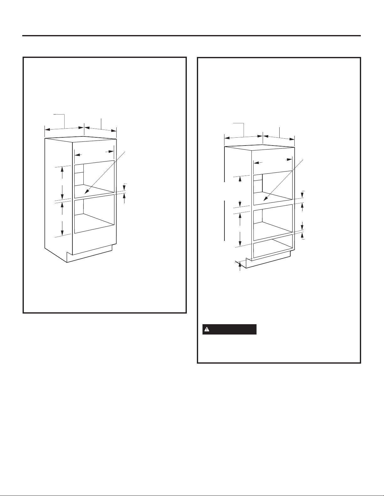
PREPARE THE OPENING (cont.)
The Advantium/Convection 120V can be installed in combination with other GE Appliances/Monogram
appliances. Always follow each product’s Installation Instructions to complete the installation.
Single Advantium/Convection 120V Installation:
Order a 30Ǝ wide single oven cabinet or cut the opening in a wall to the dimensions shown.
30Ǝ
21Ǝ
36-3/4Ǝ
Min.
STANDARD MOUNT
23-1/2Ǝ
25-1/4Ǝ
Min.
Construct
solid bottom - Min.
3/8” plywood
supported
on all four sides.
Must be able to
support weight
of oven and
contents.
FLUSH MOUNT (Monogram only)
23-1/2Ǝ
K*
22-5/8Ǝ
36-3/4Ǝ
Min.
*See table for desired reveals on sides.
Dimension 1/8”
K 30” 30-1/4”
Construct
solid bottom - Min.
3/8” plywood
supported
on all four sides.
Must be able to
support weight
of oven and
contents.
Reveal
Reveal
1/4”
• Allow 2-1/8Ǝ case trim overlap on the sides, 1-1/16Ǝ overlap on the top and 7/8Ǝ overlap on the bottom of
the opening for all models.
• Oven overlaps will conceal cut edges on all sides of the opening.
• When installed over a single oven or a warming drawer, allow at least 2Ǝ between the two openings.
This separation will provide clearance for bottom overlap of the Advantium/Convection 120V and the
other appliance overlaps.
• The support must be level and rigidly mounted, flush with the bottom edge of the cutout.
11
Page 12

Installation Instructions
1
REMOVE THE PACKAGING AND PARTS
• Remove all packing material and tape.
• Locate parts package containing mounting
screws.
• Remove the oven from the carton. Do not lift unit
by handle or conduit. Two people are required to
lift this oven.
• Open the door and remove any packaging in
oven.
4 Color-Matched Flat-Head Screws
for the Plastic Door Trim (3 required,
1 extra)
*Some models already have the trim
and screws on the door
Owner’s
Manual
Owner’s Manual
Cook Book
Glass Tray
Metal Trays (2)
(Not included with Models
CWB7030 and PWB7030)
Installation
Instructions
Cooking
Guide
Cooking Guide
Turntable Ring
5 Color-Matched Screws
(4 required, 1 extra)
Plastic Door Trim
Bottom Trim – Metal #1
Bottom Trim – Metal #2
Bottom Trim – Plastic
Plastic Door Trim X X X
Bottom Trim - Metal #1 X X Bottom Trim - Metal #2 - - X
Bottom Trim - Plastic X X X
CAUTION
If installing the Advantium/
6 Brass Screws for the
Bottom Trim
(3 required, 3 extra)
3UR¿OH Cafe Monogram
Convection 120V Oven below 36Ǝ, you must use
the plastic bottom trim due to burn risk to children.
The plastic trim acts as insulation and will help
prevent burns to children from hot surfaces.
Rack
IMPORTANT: If installing the Advantium/
Convection 120V Oven with an accessory storage
drawer, read the storage drawer assembly
instructions to assemble the products together
before proceeding to Step 2.
12
Page 13

Installation Instructions
2
DOOR TRIM REMOVAL FOR
ABOVE 36ƎINSTALLATION
ONLY
If installing the Advantium/Convection 120V
Oven above 36Ǝ from the floor, you may remove
the plastic trim from the bottom of the door for
esthetic purposes if desired.
CAUTION
Convection 120V Oven below 36Ǝ, do not
remove the plastic door trim due to burn risk
to children. The plastic trim acts as insulation
and will help prevent burns to children from hot
surfaces.
• If installing above 36Ǝ, remove the 3 screws
that secure the plastic trim to the bottom of the
door.
• Discard plastic trim. Replace screws.
If installing the Advantium/
3
SLIDE THE OVEN INTO THE
CUTOUT
CAUTION
the oven into the opening. Grasp the bottom at
front and rear. DO NOT USE THE HANDLE TO
LIFT THE OVEN. DAMAGE WILL OCCUR.
• Lift and hold the oven at the front of the opening.
Hold the oven at an angle and plug in the power
cord.
• Carefully, slide the oven into the cabinet part
way. Leave the oven a few inches forward of
the cabinet frame.
Two people are required to lift
• Check to be sure the power cord is not trapped
under the oven or along the sides of the oven.
13
Page 14

Installation Instructions
4
INSTALL BOTTOM TRIM
CAUTION
Convection 120V Oven below 36Ǝ, you must
use the plastic bottom trim due to burn risk
to children. The plastic trim acts as insulation
and will help prevent burns to children from hot
surfaces.
NOTE: If installing the Advantium/Convection
120V Oven with an accessory storage drawer,
the bottom trim is not required. Proceed to Step
5.
• Installation Below 36Ǝ, align trim tabs on the
plastic trim to slots in the bottom of the oven.
• Installation Above 36Ǝ, align trim tabs on the
plastic or metal trim to slots in the bottom of the
oven.
• Secure the bottom trim to the bottom of the
oven using 3 screws provided.
If installing the Advantium/
Plastic
Trim
Plastic
Trim OR
Metal
Trim
6
INSTALL MOUNTING SCREWS
• Slide the oven the remaining way into the
opening so that the side flanges and control
panel are against the cabinet frame. Make sure
that the oven is centered in the opening.
• Open the door, place a turntable tray in the oven
and make sure that the tray in the unit is level.
• Drill pilot holes through the side flanges.
• Drive the color-matched screws into the side
flanges. It is recommended that the screws
be hand tightened.
If installing oven with an accessory storage
drawer:
• Open the drawer.
• Drill pilot holes through the side flanges.
• Drive color-matched screws into the side flanges.
It is recommended that the screws be hand
tightened.
5
INSTALL BOTTOM TRIM WITH
ACCESSORY DRAWER
If installing with an accessory drawer, see
installation instructions that come with the
accessory drawer.
NOTE: If installing the Profile Advantium/
Convection 120V Oven with an accessory storage
drawer, you must use the Under-the-Counter
(UTC) mounting bracket for the drawer.
If installing the Monogram Advantium/Convection
integrated model
mounting bracket for the accessory storage drawer
must be used.
7
FINALIZE INSTALLATION
• Turn power on at the source. The interior light
should come on when the door is opened.
• Refer to Owner’s Manual for operating
instructions.
ZSC1201 above 36Ǝ, the UTC
14
Page 15

Notes
15
Page 16

Printed in China
NOTE: While performing installations described in this
book, safety glasses or goggles should be worn.
NOTE: Product improvement is a continuing endeavor
at GE Appliances. Therefore, materials, appearance and
specifications are subject to change without notice.
Page 17

Instrucciones
de Instalación
Hornos con Velocidad
de Cocción/Convección
Incoporada de 120V de
Advantium
CSB9120
PSB9120
ZSC1201
ZSC1202
CWB7030
PWB7030
CWB713
®
31-2000001-5
01-19 GEA
GE es una marca de la Empresa General Electric. Fabricado bajo licencia de la marca registrada.
Page 18

Información sobre Seguridad
ANTES DE COMENZAR
Lea estas instrucciones en su totalidad y
atentamente.
IMPORTANTE
para uso del inspector local.
IMPORTANTE
y ordenanzas gubernamentales.
• Nota para el Instalador — Asegúrese de que
el Comprador conserve estas instrucciones.
• Nota para el Consumidor — Guarde estas
instrucciones con su Manual del Propietario para
referencia futura.
• Nivel de habilidad — La instalación de este
electrodoméstico requiere un nivel básico de
habilidades mecánicas y eléctricas.
• Tiempo de Compleción — 1 Hora.
•
Es responsabilidad del instalador realizar una
instalación adecuada. Si se producen fallas en el
producto debido a una instalación inadecuada,
la garantía no cubrirá las mismas. Para obtener
información sobre la garantía, consulte el Manual
del Propietario.
NOTA: Sólo se aprueba la instalación de este horno
de acuerdo con los modelos específicos que aparecen
etiquetados en esta unidad.
IMPORTANTE
sólo para su propósito original. Nunca use el
electrodoméstico para calentar o calefaccionar una
habitación. El uso prolongado del horno sin una
ventilación adecuada puede ser riesgoso.
Para su seguridad personal, retire el fusible del
hogar o el disyuntor abierto antes de comenzar la
instalación, a fin de evitar lesiones graves o una
descarga mortal.
PRECAUCIÓN
poder soportar la carga del gabinete, además del
peso agregado del horno y el cajón, sumado esto a
las cargas adicionales del horno.
PRECAUCIÓN
36”, deberá usar la moldura inferior de plástico
debido a riesgos de quemaduras de los niños. La
moldura de plástico actúa como aislante y ayudará a
evitar que los niños sufran quemaduras sobre las
superficies calientes.
PRECAUCIÓN
36”, no retire la moldura de plástico de la puerta
debido al riesgo de quemaduras de los niños. La
moldura de plástico actúa como aislante y ayudará a
evitar que los niños sufran quemaduras sobre las
superficies calientes.
—
Conserve estas instrucciones
—
Cumpla con todos los códigos
—
Use este electrodoméstico
Para su seguridad personal, la
superficie de instalación deberá
Si instalará el Horno Advantium/
Convección120V por debajo de
Si instalará el Horno Advantium/
Convección 120V por debajo de
CONTENIDOS
Información de Diseños
Modelos Disponibles ................................................. 2
Dimensiones y Espacios de Despeje del Producto .. 3
Herramientas Necesarias .......................................... 3
Piezas Suministradas ................................................ 3
Planificación Anticipada ............................................3
Preparación de la Instalación
Requisitos Eléctricos ................................................. 4
Preparación de la Abertura (Estándar) .................. 5-8
Preparación de la Abertura (Montaje al Ras) ...... 9-10
Preparación del Cajón de Almacenamiento
Estándar .................................................................. 11
Al ras ....................................................................... 11
Instrucciones de Instalación
Paso 1, Retire el Embalaje y las Piezas ................. 12
Paso 2, Retiro de la Moldura de la Puerta sólo en
instalaciones superiores a 36” ................................ 13
Paso 3, Deslice el Horno por la Abertura ............... 13
Paso 4, Instale la Moldura Inferior .......................... 14
Paso 5, Instale la Moldura Inferior con el Cajón de
Accesorios ...............................................................14
Paso 6, Instale los Tornillos de Montaje ................. 14
Paso 7, Finalice la Instalación ................................14
MODELOS DISPONIBLES
Modelo Profile:
PSB9120WW–Blanco*
PSB9120BB–Negro
PSB9120SS–Acero Inoxidable
PSB9120ES–Teja
PWB7030SL–Acero Inoxidable
PWB7030EL–Teja
PSB9120BL- Acero Inoxidable Negro
Modelos de Monogram:
ZSC1201SS–Acero Inoxidable
ZSC1202SS–Acero Inoxidable**
Modelo de Café:
CSB9120SS–Acero Inoxidable
CWB7030SL–Acero Inoxidable
*Este modelo no cuenta con cajones
disponibles del mismo color.
**Esta unidad no puede instalarse con un cajón
de almacenamiento de accesorios.
2
Page 19
Información de Diseños
DIMENSIONES Y ESPACIOS DE DESPEJE DEL PRODUCTO
NOTA:El aspecto variará dependiendo del modelo.
21-1/2Ǝ
1-3/5Ǝ
1Ǝ
1-1/10Ǝ
13Ǝ
HERRAMIENTAS Y
PIEZAS REQUERIDAS (NO
SUMINISTRADAS)
• Destornillador Phillips nº 2
• Perforadora manual
• 7DODGURGHDOWDYHORFLGDGGLiPHWURGHƎ
• 'HVWRUQLOODGRUFRQSXQWD3KLOOLSVGHƎ
• Nivel
• Sierra
• &RQWUDFKDSDGRSDUDSLVRGHXQPtQGHƎVLVH
requiere)
• Tornillos de madera y otras herramientas para
instalar el riel o el estante para sostener el horno
(si se requiere)
• Anteojos o gafas de seguridad
INSTALACIÓN DEL MONTAJE AL
RAS (Monogram únicamente)
Este método de instalación permite que la cara de la
unidad quede alineada con la cara del gabinete.
IMPORTANTE: SE REQUIERE UN NIVEL DE
HABILIDAD ALTO EN CARPINTERÍA. Se podrán
adquirir gabinetes no estándares.
La instalación al ras del horno hará que se expongan
los extremos del marco de la cara del gabinete.
Los ristreles laterales podrán quedar visibles y
deberán poseer una superficie acabada.
29-3/4Ǝ
19Ǝ
PLANIFICACIÓN ANTICIPADA
• Estos hornos pueden ser instalados directamente en
un gabinete para horno de 30” de ancho, utilizando la
instalación estándar.
• Las dimensiones de altura de la abertura son diferentes
para las instalaciones con un cajón de almacenamiento
de accesorios. Asegúrese de usar el recorte correcto al
preparar la abertura.
• Deje espacio en relación a las esquinas adyacentes,
paredes, cajones, etc.
• Las alacenas instaladas al lado de hornos de pared
deben tener una especificación de adhesión de
potencia de temperatura de por lo menos 194°F.
El horno debe ser instalado de forma segura en
un gabinete que esté adherido de manera firme a
la estructura de la casa. Cualquier peso sobre la
puerta del horno podrá hacer que éste se incline y
se produzcan lesiones. Nunca permita que nadie se
trepe, siente, pare ni cuelgue de la puerta del horno.
Si instalará el accesorio para cajones, el cajón deberá
ser ensamblado al horno antes de la instalación en el
gabinete. Consulte las Instrucciones de Ensamble
del Cajón de Almacenamiento de Accesorios.
3
Page 20

Preparación de la Instalación
REQUISITOS ELÉCTRICOS
Instalación Simple del Advantium/
Convección 120:
Este producto requiere un circuito de 120 voltios, 60 Hz,
15 amperes y consume 1.8 kilowatts. Este producto se
debe conectar a un circuito con un suministro correcto
de voltaje y frecuencia.
• El tamaño del cable deberá ser conforme a los
requisitos del Código Eléctrico Nacional o del código
local obligatorio con relación a la cantidad de kilowatts.
• El cable y el enchufe de suministro de corriente se
deberán conectar al tomacorriente simple con conexión
a tierra de un disyuntor de entre 15 y 20 amperes. La
caja del tomacorriente deberá ser ubicada dentro del
alcance del cable de corriente de 48”.
UBICACIÓN ELÉCTRICA
6”
INSTRUCCIONES DE
CONEXIÓN A TIERRA
Este electrodoméstico deberá estar conectado a
tierra. En caso de que se produzca un cortocircuito,
la conexión a tierra reduce el riesgo de descarga
eléctrica, brindando un cable de escape de la corriente
eléctrica. Este electrodoméstico está equipado con un
cable de corriente que posee un cable de conexión a
tierra con un enchufe a tierra. El enchufe se deberá
colocar en un tomacorriente instalado y conectado a
tierra de forma adecuada.
9”
Ubique la caja del tomacorriente en el
área sombreada.
Instale un tomacorriente eléctrico empotrado en la
pared trasera de la abertura, dentro de las 6” de
cualquiera de los lados y a por los menos 9” sobre
el piso del recorte.
ADVERTENCIA
El uso inadecuado del
enchufe de conexión a tierra puede
provocar riesgos de descargas eléctricas.
IMPORTANTE: (Se solicita leer
detenidamente). El cable de corriente de este
electrodoméstico cuenta con un enchufe de 3 clavijas
(con cable a tierra) que se conecta a un tomacorriente
de pared estándar de 3 clavijas para minimizar la
posibilidad de descargas eléctricas. Consulte a un
electricista calificado o al personal del servicio técnico
en caso de que las instrucciones de conexión a tierra
no se entiendan completamente, o si tiene dudas
sobre si el electrodoméstico está conectado a tierra de
forma apropiada.
• En caso de contar con un receptáculo de pared de dos
clavijas, es la responsabilidad y obligación del cliente
reemplazarlo por un tomacorriente de pared de tres
clavijas correctamente conectado a tierra.
Nunca, bajo ninguna circunstancia, corte ni elimine el
tercer cable (tierra) del cable de corriente.
NO USE UN PROLONGADOR. Si el cable de
corriente es demasiado corto, solicite a un electricista
calificado o al personal del servicio técnico que instale
un tomacorriente cerca del electrodoméstico.
4
Page 21

Preparación de la Instalación Estándar
IMPORTANTE: Siempre deje una altura mínima de 36 ¾” desde el piso hasta el recorte en cualquier instalación,
ya sea simple o combinada, a menos que se instale una moldura de plástico.
PREPARACIÓN DE LA ABERTURA
El Advantium/Convección 120 puede ser instalado
junto con otros electrodomésticos de GE Appliances/
Monogram. Siempre siga las instrucciones de
instalación de cada producto, a fin de completar la
instalación.
Instalación Simple del Advantium/
Convección 120
Ordene un gabinete de horno simple de 30” de ancho
o recorte la abertura en una pared siguiendo las
dimensiones mostradas.
30”
17-1/2”
36-3/4”
Min.
23-1/2”
25-1/4”
Construya un
fondo sólido,
sostenido
por un
contrachapado
de un mínimo
de 3/8” sobre
los cuatro
lados. Deberá
poder sostener
el peso del
horno y sus
contenidos.
PREPARACIÓN DE LA ABERTURA
(CONT.)
Instalación sobre un Cajón para Calentar
de GE Appliances/Monogram:
30”
23-1/2”
25-1/4”
17-1/2”
Mín. de
36 ¾”
NOTA: Se podrán requerir despejes adicionales
entre los recortes. Asegúrese de que los soportes del
horno sobre la ubicación del Cajón para Calentar no
obstruyan la profundidad y altura internas requeridas.
Para más detalles, consulte las instrucciones de
instalación del Cajón para Calentar.
Construya un
fondo sólido,
sostenido por un
contrachapado
de un mínimo
de 3/8” sobre
los cuatro lados.
Deberá poder
sostener el peso
del horno y sus
contenidos.
Mín. de 2”
(3” Recomendado)
De acuerdo con
los requisitos
sobre el Cajón
para Calentar
• Haga que la moldura del gabinete se superponga
1 ¼” en la parte superior y 7/8” en la parte inferior,
y que haya una superposición de 2 ¼” sobre cada
lado de la abertura.
• Las superposiciones del horno ocultarán los
extremos cortantes sobre todos los costados de
la abertura. Cuando se instale sobre un horno
simple o sobre un cajón para calentar, deje por lo
menos 2” entre las dos aberturas. Esta separación
brindará espacio entre la superposición inferior del
Advantium/Convección 120 y las superposiciones
de los demás electrodomésticos.
• El soporte debe estar nivelado y montado de forma
rígida, al ras con el extremo inferior de la abertura.
5
Page 22

Preparación para la Instalación Estándar
IMPORTANTE: Siempre deje una altura mínima de 36 ¾” desde el piso hasta el recorte en cualquier instalación,
ya sea simple o combinada, a menos que se instale una moldura de plástico.
PREPARACIÓN DE LA ABERTURA
(CONT.)
Instalación sobre un Horno de GE
Appliances/Monogram:
Construya un
30”
23-1/2”
25-1/4”
17-1/2”
Mín. de
45 ¼”
* Si reemplazará un horno eléctrico doble de GE
Appliances/Monogram por la instalación combinada
de un Advantium/Convección 120 y un horno
simple, use las dimensiones mostradas. Es posible
que el riel intermedio que separa las dos aberturas
deba ser más largo que el de un mínimo de 2”
mostrado.
fondo sólido,
sostenido por un
contrachapado de
un mínimo de 3/8”
sobre los cuatro
lados. Deberá
poder sostener el
peso del horno y
sus contenidos.
Mín. de 2”
(3” Recomendado)
De Acuerdo con los
Requisitos del Horno
PREPARACIÓN DE LA ABERTURA
(CONT.)
Instalación sobre un Horno de GE
Appliances/Monogram y un Cajón para
Calentar:
30”
23-1/2”
25-1/4”
17-1/2”
45-1/4”
NOTA: Se podrán requerir despejes adicionales
entre los recortes. Asegúrese de que los soportes del
horno sobre la ubicación del Cajón para Calentar no
obstruyan la profundidad y altura internas requeridas.
Para más detalles, consulte las instrucciones de
instalación del Cajón para Calentar.
Construya un
fondo sólido,
sostenido por un
contrachapado
de un mínimo
de 3/8” sobre
los cuatro lados.
Deberá poder
sostener el peso
del horno y sus
contenidos.
Mín. de 2”
(3” Recomendado)
De Acuerdo con
los Requisitos del
Horno
Mín. de 2”
(3” Recomendado)
De acuerdo con
los requisitos
sobre el Cajón
para Calentar
PRECAUCIÓN
poder soportar la carga del gabinete, además del
peso agregado del horno y el cajón, sumado esto a
las cargas adicionales del horno.
Para su seguridad personal, la
superficie de instalación deberá
6
Page 23
Preparación para la Instalación Estándar
IMPORTANTE: Siempre deje una altura mínima de 36 ¾” desde el piso hasta el recorte en cualquier instalación,
ya sea simple o combinada, a menos que se instale una moldura de plástico.
PREPARACIÓN DE LA ABERTURA
(cont.)
Instalación sobre otro Horno con
Velocidad de Cocción Incorporada de GE
Appliances/ Monogram:
30Ǝ
23-1/2Ǝ
25-1/4Ǝ
17-1/2Ǝ
17-1/2Ǝ
•
Si montará un horno de Velocidad de Cocción
Incorporado de GE Appliances/ Monogram sobre
otro, use las dimensiones mostradas. Es posible
que el riel intermedio que separa las dos aberturas
deba ser más largo que el de un mínimo de 2”
mostrado.
Construya un
fondo sólido,
sostenido por un
contrachapado de
un mínimo de 3/8”
sobre los cuatro
lados. Deberá
poder sostener el
peso del horno y
sus contenidos.
Mín. de 2” (3”
Recomendado)
PREPARACIÓN DE LA ABERTURA
(cont.)
Instalación debajo de un Horno
Microondas de GE Appliances/
Monogram y sobre un Cajón para
Calentar:
30Ǝ
De Acuerdo con
los Requisitos del
Horno Microondas
17-1/2Ǝ
De acuerdo
con los
requisitos
sobre el Cajón
para Calentar
NOTA: Se podrán requerir despejes adicionales
entre los recortes. Asegúrese de que los soportes del
horno sobre la ubicación del Cajón para Calentar no
obstruyan la profundidad y altura internas requeridas.
Para más detalles, consulte las instrucciones de
instalación del Cajón para Calentar.
23-1/2Ǝ
25-1/4Ǝ
Construya un
fondo sólido,
sostenido por un
contrachapado de
un mínimo de 3/8”
sobre los cuatro
lados. Deberá
poder sostener el
peso del horno y
sus contenidos.
Mín. de 3.5”
(4.5” Recomendado)
Mín. de 2”
(3” Recomendado)
PRECAUCIÓN
poder soportar la carga del gabinete, además del
peso agregado del horno y el cajón, sumado esto a
las cargas adicionales del horno.
Para su seguridad personal, la
superficie de instalación deberá
7
Page 24
Preparación para la Instalación Estándar
IMPORTANTE: Siempre deje una altura mínima de 36 ¾” desde el piso hasta el recorte en cualquier instalación,
ya sea simple o combinada, a menos que se instale una moldura de plástico.
PREPARACIÓN DE LA ABERTURA
(cont.)
Instalación junto a otro Horno con
Velocidad de Cocción Incorporada de GE
Appliances/ Monogram:
• Si montará un horno de Velocidad de Cocción
Incorporado de GE Appliances/ Monogram junto a
otro, use las dimensiones mostradas. Es posible
que el riel intermedio que separa las dos aberturas
deba ser más largo que el de un mínimo de 4 ½”
mostrado.
17-1/2Ǝ
PREPARACIÓN DE LA ABERTURA (cont.)
25-1/4Ǝ
23-1/2Ǝ
25-1/4Ǝ
17-1/2Ǝ
Mín. de 4 ½” (5 ½”
Recomendado)
Instalación debajo de una Superficie de Cocción o Mesada de 30” o 36” de GE Appliances/
Monogram:
Las superficies de cocción a gas o eléctricas podrán ser instaladas sobre este horno. Para conocer el tamaño
de la abertura, consulte las instrucciones de instalación de la superficie de cocción. Consulte la etiqueta en la
parte superior del horno para conocer los modelos con superficie de cocción aprobados. Este horno requiere un
suministro de corriente aparte, adecuadamente conectado a tierra de 15 amperes, 120 voltios y 60 Hz. La superficie
de cocción requiere un sumistro de corriente aparte. Use un gabinete de 36” o con una base más ancha.
Mín de 1 ½”
25Ǝ
36Ǝ Altura
de la Mesada
Ǝ
Altura de la superficie de cocción,
incluyendo la profundidad de la
caja eléctrica en algunos modelos.
Consulte las instrucciones de
Instalación de la superficie de cocción.
No se requiere ningún espacio de
despeje mínimo entre la superficie de
cocción y el horno.
23-1/2
Ǝ
Superficie
de cocción
Superficie
de cocción
17-1/2
25-1/4Ǝ
Zócalo
de 4” de
Altura
NOTA: Sólo se aprueba la instalación de este horno
de acuerdo con los modelos específicos que aparecen
etiquetados en esta unidad.
8
Page 25

Preparación de la Instalación para el Montaje al Ras
(Monogram Únicamente)
IMPORTANTE: Siempre deje una altura mínima de 36 ¾” desde el piso hasta el recorte en cualquier instalación,
ya sea simple o combinada, a menos que se instale una moldura de plástico.
PREPARE EL INTERIOR
Corte e instale los ristreles laterales:
• Corte los ristreles de madera laterales a la altura de
la abertura del gabinete y a aproximadamente 2 1/2”
de profundidad. Instale, a cada lado, a 1 3/8” desde
la cara frontal del gabinete.
Corte e instale el ristrel inferior:
• Corte el ristrel de madera a una altura de 1 1/8”,
una profundidad del gabinete menos 1 3/8” y un
ancho de 25 ¼” para que coincida entre los ristreles
laterales. Instale en el piso del gabinete entre los
ristreles laterales, persione el mismo completamente
hacia atrás contra la pared del gabinete y asegúrese
de que su cara frontal se alinee con las caras
frontales de los ristreles laterales (brecha de 1 3/8”
desde la cara frontal del gabinete).
A A
PREPARACIÓN DE LA ABERTURA
El Advantium 120 puede ser instalado junto con otros
electrodomésticos de GE Appliances/Monogram.
Siempre siga las instrucciones de instalación de cada
producto, a fin de completar la instalación.
Instalación Simple de Advantium 120
Corte la abertura en un gabinete siguiendo las
dimensiones mostradas.
*Consulte la siguiente
tabla para conocer
las fugas deseadas a
los costados.
**19-1/4”
0tQGHƎ
F *
Horno o
cajón para
calentar
Construya un
fondo sólido,
sostenido por un
contrachapado
de un mínimo
de 3/8” sobre
los cuatro lados.
Deberá poder
sostener el peso
del horno y sus
contenidos.
Mín. de 2”
Especificaciones
por
electrodoméstico
C
B
A Profunidad de los ristre-
les laterales
B Altura del ristrel inferior 1-1/8”
C Profundidad del ristrel
inferior
D Ancho del ristrel inferior 25-1/4”
E Los tres ristreles Empotre e instale a 1 3/8” des-
0tQGHƎ
Profundidad del gabinete
menos 1 3/8”
GHODVXSHU¿FLHDOUDVGHVHDGD
D
E
D
VISTA
C
SUPERIOR
A A
Cara Frontal del Gabinete
EE
Mín. de
36 ¾”
• El soporte debe estar nivelado y montado de forma
rígida, al ras con el extremo inferior de la abertura.
Instalación al Ras Aprobada
Advantium Simple 30” 30-1/4”
Sobre el Cajón para Calentar 30” 30Sobre el Horno
Sobre el Horno y el Cajón para
Calentar
Sobre el Horno con Velocidad de
Cocción Incorporada
Advantium Doble (lado a lado)
'HEDMRGHOD6XSHU¿FLHGH&RFFLyQR
de la Mesada
Dimensión F
Fuga de 1/8” Fuga de 1/4”
30” 30-1/4”
30” 30-1/4”
30” 30-1/4”
Lea la página 10
Lea la página 10
** Las fugas superior e inferior están configuradas en
1/8”.
9
1
/4”
Page 26

Preparación de la Instalación para el Montaje al Ras
IMPORTANTE: Siempre deje una altura mínima de 36 ¾” desde el piso hasta el recorte en cualquier instalación,
ya sea simple o combinada, a menos que se instale una moldura de plástico.
(Monogram Únicamente)
PREPARACIÓN DE LA ABERTURA
El Advantium/Convección 120 puede ser instalado junto
a otro Advantium/Convección 120 combinando uno al
lado del otro.
Instalación del Advantium/Convección 120
Doble:
Corte la abertura en un gabinete siguiendo las
dimensiones mostradas.
• El divisor central actúa como un ristrel para el lado de
cada unidad respectiva. Sólo un ristrel lateral adicional
es necesario de acuerdo con la abertura del horno.
• El soporte debe estar nivelado y montado de forma
rígida, al ras con el extremo inferior de la abertura.
*Consulte la tabla para conocer las fugas necesarias a los costados y entre la unidad.
Dimensión Fuga de 1/8” Fuga de 1/4”
G 59-7/8” 60-1/4”
H 5-1/8” 5-1/4”
I 27-3/8” 27-1/2”
Mín. de
G*
H*
I*
19-1/4”
36-3/4”
Construya un fondo sólido,
sostenido por contrachapado de
un mínimo de 3/8” sobre los cuatro
lados. Deberá poder sostener el
peso del horno y sus contenidos.
Mín. de 23-1/2”
I*
1-3/8”
Instalación debajo de una Superficie de Cocción o Mesada de 30” o 36” de GE
Appliances/ Monogram:
Las superficies de cocción a gas o eléctricas podrán ser instaladas sobre este horno. Para conocer el tamaño
de la abertura, consulte las instrucciones de instalación de la superficie de cocción. Consulte la etiqueta en la
parte superior del horno para conocer los modelos con superficie de cocción aprobados. Este horno require un
suministro de corriente aparte, adecuadamente conectado a tierra de 15 amperes, 120 voltios y 60 Hz. Use un
gabinete de 36” o con una base más ancha.
Superficie
de cocción
Superficie
de cocción
Mín de 1-1/2Ǝ
25Ǝ
23-1/2
Zócalo
de 4” de
Altura
Altura de
la Mesada
de 36”
19-1/4”
J*
Altura de la superficie de cocción, incluyendo la profundidad
Ǝ
NOTA: Sólo se aprueba la instalación de este
horno de acuerdo con los modelos específicos
que aparecen etiquetados en esta unidad.
de la caja eléctrica en algunos modelos. Consulte las
instrucciones de Instalación de la superficie de cocción.
No se requiere ningún espacio de despeje mínimo entre la
superficie de cocción y el horno.
*Consulte la siguiente tabla para conocer las
fugas deseadas a los costados.
Dimensión Fuga de
1/8”
J 30” 30-1/4”
Fuga de
1/4”
10
Page 27

Preparación de la Instalación
Preparación CON un Cajón de Almacenamiento de Accesorios
• PSB9120 y PWB7030 son los únicos modelos aprobados para su instalación debajo de una altura
de 36 3/4” con un cajón de almacenamiento. CSB9120, ZSC1201, ZSC1202 y CWB7030 no están
aprobados.
• Según sea necesario, consulte la Preparación para la Instalación de Montaje Estándar O la
Preparación para la Instalación de Montaje al Ras para conocer los detalles de la configuración. A
continuación, observe la altura de la abertura modificada.
• Modelo ZSC1202 no pueden instalarse con un cajón de almacenamiento de accesorios. Ver
preparacion para la instalación sin un cajón de almacenamiento de accesorios para este modelo.
PREPARACIÓN DE LA ABERTURA (cont.)
El Advantium/Convección 120V puede ser instalado junto con otros electrodomésticos de GE Appliances/
Monogram. Siempre siga las instrucciones de instalación de cada producto, a fin de completar la instalación.
Instalación Simple de Advantium/Convección 120V:
Ordene un gabinete para horno simple de 30” de ancho o recorte la abertura en una pared siguiendo las
dimensiones mostradas.
INSTALACIÓN DEL MONTAJE AL RAS
MONTAJE ESTÁNDAR
(Monogram únicamente)
30Ǝ
21Ǝ
36-3/4Ǝ
Min.
• Permita que haya una superposición de la moldura de la caja de 2 1/8” sobre los costados, una superposición de
1 1/16” en la parte superior, y una superposición de 7/8” en la parte inferior de la abertura para todos los modelos.
• Las superposiciones del horno ocultarán los extremos cortantes sobre todos los costados de la abertura.
• Cuando se instale sobre un horno simple o sobre un cajón para calentar, deje por lo menos 2” entre las dos
aberturas. Esta separación brindará espacio para la superposición inferior del Advantium/Convección 120V y las
superposiciones de los demás electrodomésticos.
• El soporte debe estar nivelado y montado de forma rígida, al ras con el extremo inferior de la abertura.
23-1/2Ǝ
Mín. de
25-1/4Ǝ
Construya un
fondo sólido,
sostenido por un
contrachapado de
un mínimo de 3/8”
sobre los cuatro
lados. Deberá
poder sostener el
peso del horno y
sus contenidos.
22-5/8Ǝ
Mín. de
36-3/4Ǝ
23-1/2Ǝ
K*
Construya un
fondo sólido,
sostenido por un
contrachapado de
un mínimo de 3/8”
sobre los cuatro
lados. Deberá
poder sostener el
peso del horno y
sus contenidos.
*Consulte la siguiente tabla para conocer las
fugas deseadas a los costados.
Dimensión Fuga de
1/8”
K 30” 30-1/4”
Fuga de
1/4”
11
Page 28

Instrucciones de Instalación
1
RETIRE EL EMBALAJE Y LAS PIEZAS
• Retire todo el material de embalaje y la cinta.
• Ubique el paquete de piezas que contiene los tornillos
de montaje.
• Retire el horno del cartón. No levante la unidad de la
manija ni del conducto. Es necesario que el horno sea
levantado por dos personas.
• Abra la puerta y retire cualquier embalaje que haya
dentro del horno.
Owner’s
Manual
Manual del
Propietario
Instrucciones
de Instalación
Cooking
Guide
4 Tornillos de Cabeza Plana del Mismo
Color para la Moldura de la Puerta de
(3 requeridos, 1 adicional)
*Algunos modelos ya cuentan con la
moldura y los tornillos en la puerta.
5 Tornillos del Mismo
Color
(4 requeridos, 1
adicional)
Moldura de la Puerta de Plástico
Moldura Inferior – Metálica nº 1
Plástico
6 Tornillos de Latón para la
Moldura Inferior
(3 requeridos,
3 adicionales)
Libro de Cocina
Bandeja de Vidrio
Bandejas de Metal (2)
(No se incluye con modelos
CWB7030 y PWB7030)
Guía de
Cocción
Anillo del Plato Giratorio
Estante
Moldura Inferior – Metálica nº 2
Moldura Inferior - Plástica
3UR¿OH Café Monogram
Moldura de la Puerta de
Plástico
Moldura Inferior – Metálica nº 1
Moldura Inferior – Metálica nº 2
Moldura Inferior - Plástica
PRECAUCIÓN
Si instalará el Horno Advantium/
Convección 120V por debajo de
XX X
XX -
-- X
XX X
36”, deberá usar el borde inferior de plástico debido a
riesgos de quemaduras de los niños. El borde de
plástico actúa como aislante y ayuda a evitar que los
niños sufran quemaduras sobre las superficies
calientes.
IMPORTANTE: Si instalará el Horno Advantium/
Convección 120V con un cajón de almacenamiento de
accesorios, lea las instrucciones de ensamble del cajón
de almacenamiento para ensamblar los productos juntos,
antes de proceder al paso 2.
12
Page 29

Instrucciones de Instalación
2
RETIRO DE LA MOLDURA DE
LA PUERTA PARA
INSTALACIONES SUPERIORES
A 36” ÚNICAMENTE
Si instalará el Horno Advantium/Convección 120V
por encima de 36” desde el piso, podrá retirar la
moldura plástica de la parte inferior de la puerta por
cuestiones estéticas.
PRECAUCIÓN
36”, no retire el borde de la puerta de plástico
debido al riesgo de quemaduras de los niños. El
borde de plástico actúa como aislante y ayuda a
evitar que los niños sufran quemaduras sobre las
superficies calientes.
• Si realizará una instalación por encima de 36”, retire
los 3 tornillos que aseguran la moldura de plástico
a la parte inferior de la puerta.
• Descarte la moldura de plástico. Reemplace los
tornillos.a la parte inferior de la puerta.
Si instalará el Horno Advantium/
Convección 120V por debajo de
3
DESLICE EL HORNO POR LA
ABERTURA
PRECAUCIÓN
la abertura. Se deberá tomar la parte inferior sobre la
parte frontal y trasera. NO USE LA MANIJA PARA
LEVANTAR EL HORNO. SE PRODUCIRÁN DAÑOS.
• Levante y sostenga el horno desde el frente de
la abertura. Sostenga el horno en un ángulo y
enchufe el cable de corriente.
• Con cuidado, deslice el horno sólo hasta una parte
dentro del gabinete. Deje el horno a unas pocas
pulgadas delante de la estructura del gabinete.
• Asegúrese de que el cable de corriente no quede
atrapado debajo del horno ni a lo largo de los
costados del horno.
Se requiere contar con dos
personas para colocar el horno en
13
Page 30

Instrucciones de Instalación
4
INSTALE LA MOLDURA
INFERIOR
PRECAUCIÓN
36”, deberá usar el borde inferior de plástico debido a
riesgos de quemaduras de los niños. El borde de
plástico actúa como aislante y ayudará a evitar que
los niños sufran quemaduras sobre las superficies
calientes.
NOTA: Si instalará el Horno Advantium/Convección
120V con un cajón de almacenamiento de
accesorios, la moldura inferior no será necesaria.
Proceda al Paso 5.
• En la Instalación por debajo de 36”, alinee las
lengüetas de la moldura sobre la moldura de plástico
con las ranuras de la parte inferior del horno.
• En la Instalación por encima de 36”, alinee las
lengüetas de la moldura sobre la moldura de plástico
con las ranuras de la parte inferior del horno.
Si instalará el Horno Advantium/
Convección 120V por debajo de
Moldura
de
Plástico
Moldura de
Plástico O
6
INSTALACIÓN DE LOS
TORNILLOS DE MONTAJE
• Deslice el horno por el resto del recorrido hasta la
abertura, de modo que las pestañas laterales y el
panel de control queden contra la estructura del
gabinete. Asegúrese de que el horno quede centrado
en la abertura.
• Abra la puerta, coloque una bandeja giratoria en el
horno y asegúrese de que la misma quede nivelada
en la unidad.
• Haga agujeros piloto a través de las pestañas
laterales.
• Coloque los tornillos del mismo color en las pestañas
laterales. Se recomienda que los tornillos sean
ajustados de forma manual.
Si instalará el horno con un cajón de
almacenamiento de accesorios:
• Abra el cajón.
• Haga agujeros piloto a través de las pestañas
laterales.
• Coloque los tornillos del mismo color en las pestañas
laterales. Se recomienda que los tornillos sean
ajustados de forma manual.
Moldura
de Metal
• Asegure la moldura inferior con la parte inferior del
horno usando los 3 tornillos provistos.
5
INSTALACIÓN DE LA
MODLURA INFERIOR CON EL
CAJÓN DE ACCESORIOS
Si hará la instalación con un cajón de accesorios,
consulte las instrucciones de instalación que se
incluyen con el cajón de accesorios.
NOTA: Si instalará el Horno Profile Advantium/
Convección/Convección 120V con un cajón de
almacenamiento de accesorios, deberá usar el soporte
de montaje para uso debajo de la mesada para el
cajón.
Si instalará el modelo integrado Monogram Advantium/
Convección ZSC1201 por encima de 36”, se deberá
usar el soporte de montaje para uso debajo de la
mesada con el cajón de almacenamiento de accesorios.
7
FINALIZACIÓN DE LA
INSTALACIÓN
• Presione el encendido. La luz interna se deberá
encender cuando la puerta se abra.
• Para acceder a instrucciones de uso, consulte el
Manual del Propietario.
14
Page 31

Notas
15
Page 32

Impreso en China
NOTA: Al realizar las instalaciones descriptas en este libro, se
deberán usar anteojos o gafas de seguridad.
NOTA: GE Appliances se esfuerza de forma constante para
mejorar sus productos. Por lo tanto, los materiales, el aspecto
y las especificaciones están sujetos a cambios sin aviso previo.
 Loading...