

CAEN
Tools
for Discovery
Electronic Instrumentation
Es
UM2619
N1419 User Manual
Rev. 2 - 22 March 2013

Purpose of this Manual
This document is the N1419 User's Manual; it contains information about the installation, the configuration and the
use of the Power Supply System.
Change Document Record
Date
Revision
Changes
30 May 2012
Rev. 0
Internal use
30 November 2012
Rev. 1
Preliminary
22 March 2013
Rev. 2
Polarity change instructions update
Symbols, abbreviated terms and notation
T.B.D.
Reference Documents
T.B.D.
Disclaimer
No part of this manual may be reproduced in any form or by any means, electronic, mechanical, recording, or
otherwise, without the prior written permission of CAEN SpA.
CAEN will repair or replace any product within the guarantee period if the Guarantor declares that the product is
defective due to workmanship or materials and has not been caused by mishandling, negligence on behalf of the User,
accident or any abnormal conditions or operations.
CAEN declines all responsibility for damages or injuries caused by an improper use of the Modules due to negligence on
behalf of the User. It is strongly recommended to read thoroughly the CAEN User's Manual before any kind of
operation. CAEN reserves the right to change partially or entirely the contents of this Manual at any time and without
giving any notice.
Disposal of the Product The product must never be dumped in the Municipal Waste. Please check your local regulations
for disposal of electronics products.
Made In Italy : We stress the fact that all the boards are made in Italy because in this globalized world, where getting
the lowest possible price for products sometimes translates into poor pay and working conditions for the people who
make them, at least you know that who made your board was reasonably paid and worked in a safe environment. (this
obviously applies only to the boards marked "made in italy", we cannot attest to the manufacturing process of "third
party" boards).

CAEN
Electronic Instrumentation
UM2619 – N1419 User Manual
3
Index
1. General description ............................................................................................................ 5
Overview ................................................................................................................................................................... 5
2. Technical specifications ...................................................................................................... 6
Packaging .................................................................................................................................................................. 6
Power requirements ................................................................................................................................................. 6
Front and back panel ................................................................................................................................................ 8
Front panel connections ......................................................................................................................................... 10
Local control section ............................................................................................................................................................10
Channel control section .......................................................................................................................................................10
HV Status control section .....................................................................................................................................................11
Alarm signal ...............................................................................................................................................................................11
Interlock signal ...........................................................................................................................................................................11
Remote communication control section ..............................................................................................................................12
Rear panel connections .......................................................................................................................................... 13
HV Channel Output ..............................................................................................................................................................13
Imon Zoom .............................................................................................................................................................. 13
Technical specifications table ................................................................................................................................. 14
3. Operating modes .............................................................................................................. 15
Programmable parameters ..................................................................................................................................... 15
Boards parameters ...............................................................................................................................................................15
Channel settings ...................................................................................................................................................................16
Local Control ........................................................................................................................................................... 17
HV connection ......................................................................................................................................................................17
Module settings ...................................................................................................................................................................18
Channel settings ...................................................................................................................................................................19
Group Settings ...........................................................................................................................................................................21
Smileys .......................................................................................................................................................................................23
Current monitor offset calibration ......................................................................................................................... 23
Remote Control ...................................................................................................................................................... 24
Serial Links............................................................................................................................................................................24
USB communication ..................................................................................................................................................................24
RS232 communication ...............................................................................................................................................................24
RS485 communication ...............................................................................................................................................................25
Ethernet communication ...........................................................................................................................................................25
Communication Control .......................................................................................................................................................26
Remote Control: Main Menu .....................................................................................................................................................26
Remote Control: General Menu ................................................................................................................................................27
Remote Control: Channels Menu ..............................................................................................................................................27
Remote Control: firmware upgrade...........................................................................................................................................28
Remote Control: format EEPROM .............................................................................................................................................29
Remote Control: Current offset calibration ...............................................................................................................................29
USB - RS485 Communication Protocol ................................................................................................................... 30
Command Format ................................................................................................................................................................30
Format of response string ....................................................................................................................................................30
MONITOR commands related to the Channels ....................................................................................................................30
Meaning of STATUS bits (value read in decimal Format) ...........................................................................................................31
MONITOR commands related to the module ......................................................................................................................32
Meaning of Board Alarm bits .....................................................................................................................................................33
SET commands related to the Channels ...............................................................................................................................33
SET commands related to the module .................................................................................................................................33
4. Internal Settings ............................................................................................................... 34
Polarity selection .................................................................................................................................................... 34
Internal switches ..................................................................................................................................................... 36
Local Bus termination ..........................................................................................................................................................36
RS485 – RS232 conversion ...................................................................................................................................................36
List of Figures
Fig. 1: Mod. 1419 series ...........................................................................................................................................................................5
Fig. 2: Backplane NIM connector .............................................................................................................................................................7

CAEN
Electronic Instrumentation
UM2619 – N1419 User Manual
4
Fig. 3: Mod. N1419 series front panel (std., A, B) ....................................................................................................................................8
Fig. 4: Mod. N1419 series back panel (std., A, B) .....................................................................................................................................9
Fig. 5: Local control panel ......................................................................................................................................................................10
Fig. 6: Channel control panel and Kill scheme .......................................................................................................................................10
Fig. 7: N1419 HV Status control panel ...................................................................................................................................................11
Fig. 8: N1419 ALARM electrical scheme ................................................................................................................................................11
Fig. 9: N1419 ALARM TTL configured ....................................................................................................................................................11
Fig. 10: N1419 INTERLOCK electrical scheme ........................................................................................................................................11
Fig. 11: Remote communication control and RS485 I/O – RS232 IN electrical scheme .........................................................................12
Fig. 12: HV Channel panel and test point electrical scheme ..................................................................................................................13
Fig. 13: Welcome screen........................................................................................................................................................................17
Fig. 14: Channel OFF status screen ........................................................................................................................................................17
Fig. 15: Channel ON status screen .........................................................................................................................................................17
Fig. 16: Channel KILL status screen ........................................................................................................................................................17
Fig. 17: Mode settings status screen .....................................................................................................................................................18
Fig. 18: Mode settings access screen .....................................................................................................................................................18
Fig. 19: Mode settings edit screen .........................................................................................................................................................18
Fig. 20: Channel settings edit screen .....................................................................................................................................................19
Fig. 21: Channel VSET select screen .......................................................................................................................................................19
Fig. 22: Channel VSET access screen ......................................................................................................................................................19
Fig. 23: Channel VSET digit selection screen ..........................................................................................................................................19
Fig. 24: Channel VSET digit access screen ..............................................................................................................................................20
Fig. 25: Channel VSET digit adjust screen ..............................................................................................................................................20
Fig. 26: Channel VSET digit confirm screen ............................................................................................................................................20
Fig. 27: Channel VSET confirm screen....................................................................................................................................................20
Fig. 28: Channel VSET de-select screen .................................................................................................................................................20
Fig. 29: Channel KILL screen ..................................................................................................................................................................21
Fig. 30: Channel EXIT screen ..................................................................................................................................................................21
Fig. 31: Group selection .........................................................................................................................................................................21
Fig. 32: Group active ..............................................................................................................................................................................21
Fig. 33: Group VSET access screen .........................................................................................................................................................22
Fig. 34: Group VSET digit selection screen .............................................................................................................................................22
Fig. 35: Group Channel VSET digit access screen ...................................................................................................................................22
Fig. 36: Group VSET digit adjust screen .................................................................................................................................................22
Fig. 37: Group VSET digit confirm screen ...............................................................................................................................................22
Fig. 38: Channel VSET de-select screen .................................................................................................................................................23
Fig. 39: Group EXIT screen .....................................................................................................................................................................23
Fig. 40: USB communication diagram ....................................................................................................................................................24
Fig. 41: RS232 communication diagram ................................................................................................................................................24
Fig. 42: RS485 communication diagram ................................................................................................................................................25
Fig. 43: Ethernet communication diagram ............................................................................................................................................25
Fig. 44: RS232 port cable adapter ..........................................................................................................................................................26
Fig. 45: Main Menu ................................................................................................................................................................................26
Fig. 46: Board Status Menu ...................................................................................................................................................................27
Fig. 47: Channels Menu .........................................................................................................................................................................27
Fig. 48: PC keyboard ..............................................................................................................................................................................27
Fig. 49: Channels group setting .............................................................................................................................................................28
Fig. 50: Firmware Upgrade Menu/1 ......................................................................................................................................................28
Fig. 51: Firmware Upgrade Menu/2 ......................................................................................................................................................28
Fig. 52: Format EEPROM Menu .............................................................................................................................................................29
Fig. 53: Current offset calibration warning ............................................................................................................................................29
Fig. 54: Current offset calibration VSET selection ..................................................................................................................................29
Fig. 55: Current offset calibration confirmation ....................................................................................................................................30
Fig. 56: Side cover removal instructions ................................................................................................................................................34
Fig. 57: Polarity selection instructions ..................................................................................................................................................35
Fig. 58: Dip switch position ....................................................................................................................................................................36
List of Tables
Table 1: Available items ...........................................................................................................................................................................5
Table 2: Power requirements ..................................................................................................................................................................6
Table 3: Interlock operation ..................................................................................................................................................................12
Table 4: Mod. N1419 Channel technical specifications .........................................................................................................................14
Table 5: Smileys list ...............................................................................................................................................................................23
CAEN
Electronic Instrumentation
UM2619 – N1419 User Manual
5
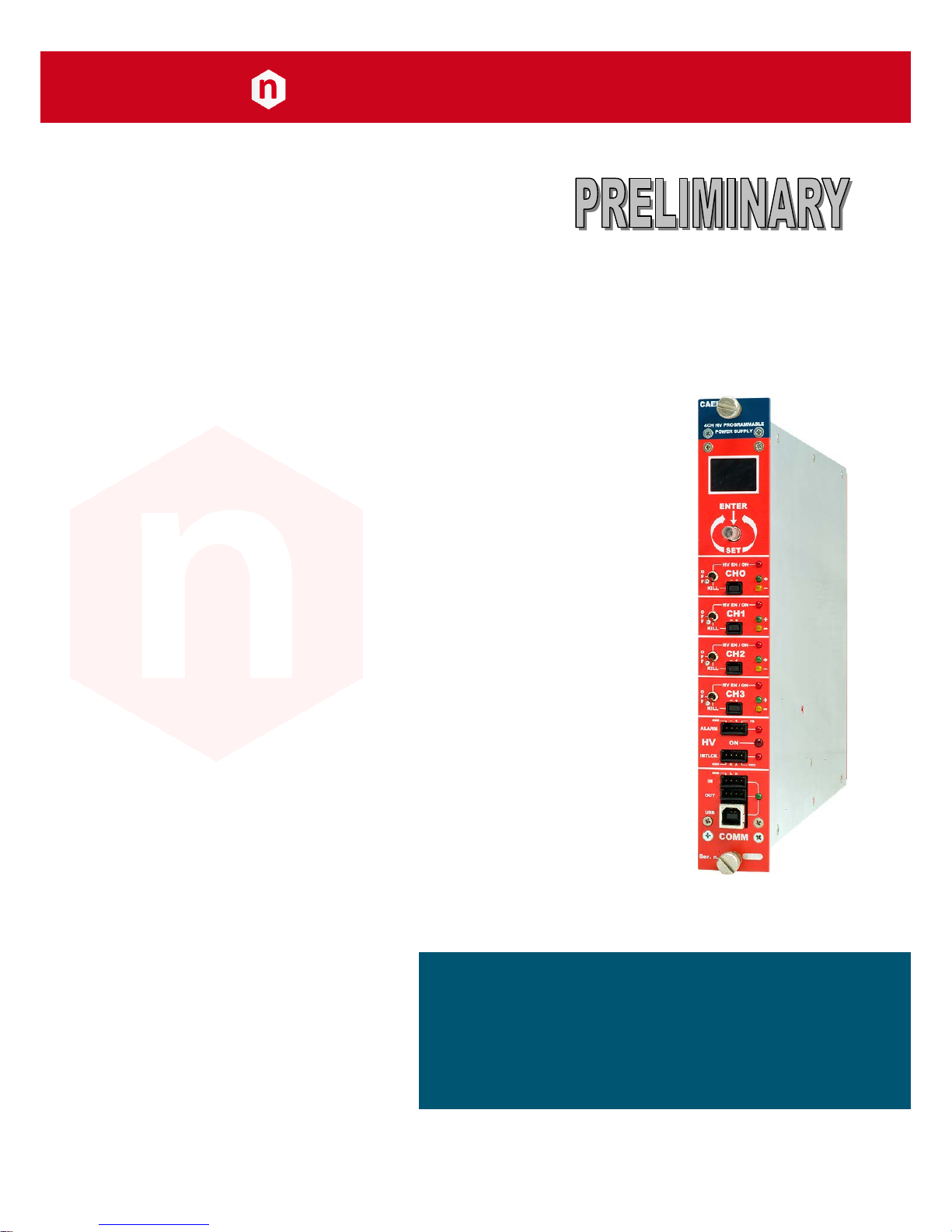
1. General description
Overview
Fig. 1: Mod. 1419 series
The Mod. N1419 provides 4 independent High Voltage channels in a single width NIM mechanics. Two and one
channel versions (N1419A and N1419B) are also available.
Each channel can provide a ±500V / 200 µA max output.
Channels have common floating return (common return insulated from the crate ground); HV outputs are delivered
through SHV connectors.
The HV output RAMP-UP and RAMP-DOWN rates may be selected independently for each channel in the range
1÷50 V/s in 1 V/s steps.
Safety features include:
• OVERVOLTAGE and UNDERVOLTAGE warning when the output voltage differs from the programmed value by
more than 2% of set value (minimum 1V).
• Programmable VMAX protection limit
• OVERCURRENT detection: if a channel tries to draw a current larger than its programmed limit, it enters TRIP
status, keeping the maximum allowed value for a programmable time (TRIP), before being switched off
• Channels can be enabled or disabled individually through the Interlock logic.
Module control can take place either locally, assisted by a Graphic color display or remotely, via USB, RS232 or
RS485; the RS485 port allows to build a N1419s’ daisy chain network (up to 32 modules); in this case the SW1470
Control Software is necessary (see download section on www.caen.it).
The Mod. A1480 is an optional DC Input Power Equalizer which allows to use a different input power distribution on
the N147x modules.
Table 1: Available items
Code
Item
Description
WN1419XAAAAA
N1419
4 Channels, local & remote control, NIM HV Power Supply (±500V, 200uA, 10nA res.)
WN1419AXAAAA
N1419A
2 Channels, local & remote control, NIM HV Power Supply (±500V, 200uA, 10nA res.)
WN1419BXAAAA
N1419B
1 Channel, local & remote control, NIM HV Power Supply (±500V, 200uA, 10nA res.)
WA1480XAAAAA
A1480
DC Power Input Equalizer for N147X Family
WPERS0147001
Customization
Imon Zoom x10
CAEN
Electronic Instrumentation
UM2619 – N1419 User Manual
6
2. Technical specifications
Packaging
The Mod. N1419 boards are housed in a single width NIM modules.
Power requirements
Table 2: Power requirements
Board type
N
1419
Channel configuration
without A1480
with A1480
N° ch ON
Current (± 12V)
Current (±6V)
n° ch ON
Current (± 12V)
Current (±6V)
3
00V/200µA
4 CH T.B.D.
none
4 CH
T.B.D T.B.D 5
00V/20µA
4 CH T.B.D
none
4 CH
T.B.D T.B.D 5
00V/200µA
4 CH T.B.D
none
4 CH
T.B.D T.B.D
Board type
N
1419A
Channel configuration
without A1480
with A1480
N° ch ON
Current (± 12V)
Current (±6V)
n° ch ON
Current (± 12V)
Current (±6V)
3
00V/200µA
2 CH T.B.D
none
2 CH
T.B.D T.B.D 5
00V/20µA
2 CH T.B.D
none
2 CH
T.B.D
T.B.D
5
00V/200µA
2 CH T.B.D
none
2 CH
T.B.D T.B.D
Board type
N
1419B
Channel configuration
without A1480
with A1480
N° ch ON
Current (± 12V)
Current (±6V)
n° ch ON
Current (± 12V)
Current (±6V)
3
00V/200µA
1 CH T.B.D
none
1 CH
T.B.D T.B.D 5
00V/20µA
1 CH T.B.D
none
1 CH
T.B.D T.B.D 5
00V/200µA
1 CH T.B.D
none
1 CH
T.B.D T.B.D
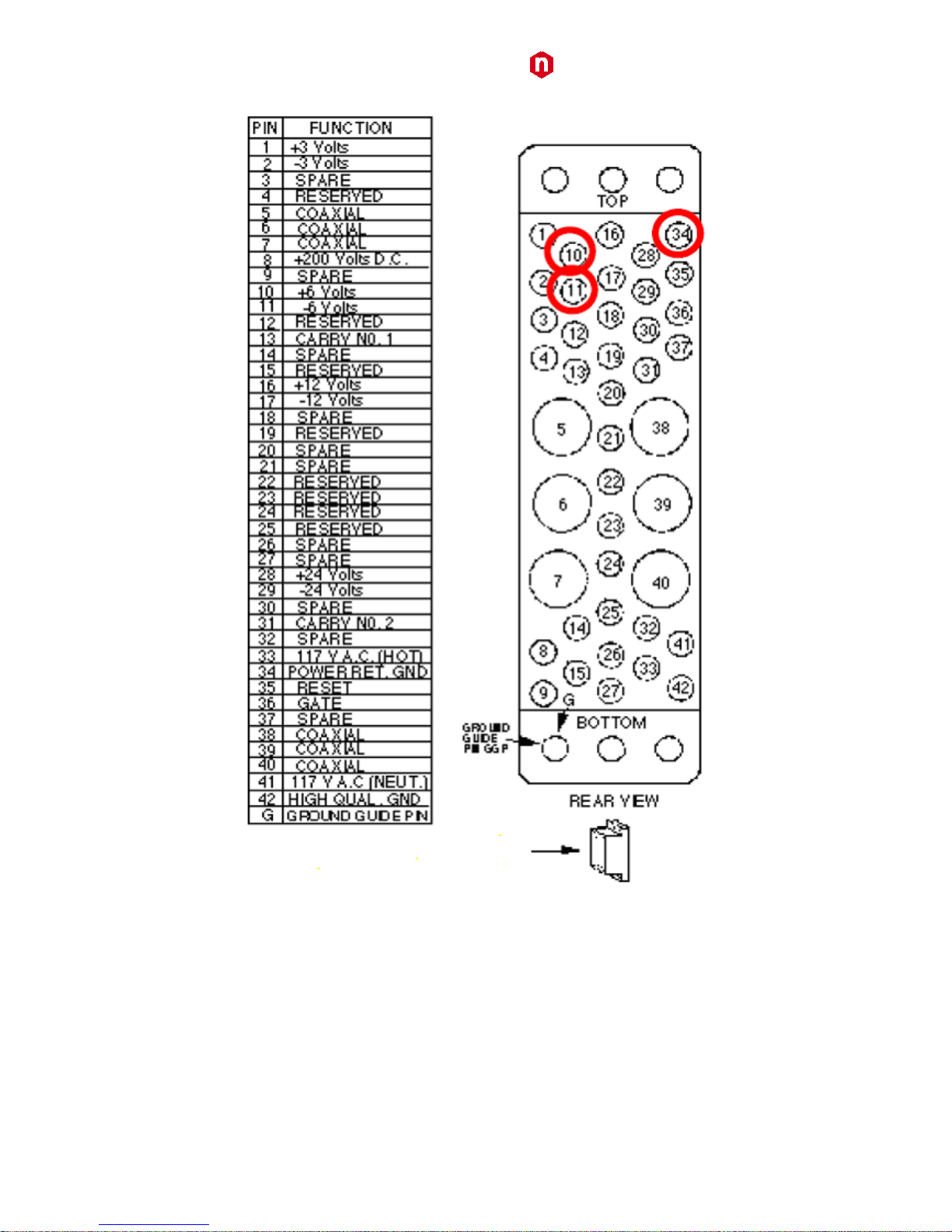
WARNING: if the A1480 is not installed, ±6V power supplies are not required and power pins 10 and 11 on the
backplane NIM connector are not installed (see Fig. 2).
CAEN
Electronic Instrumentation
UM2619 – N1419 User Manual
7
Fig. 2: Backplane NIM connector

CAEN
Electronic Instrumentation
UM2619 – N1419 User Manual
8
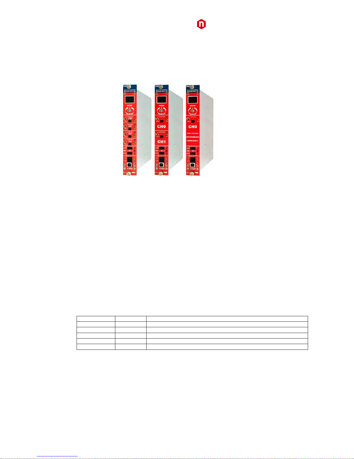
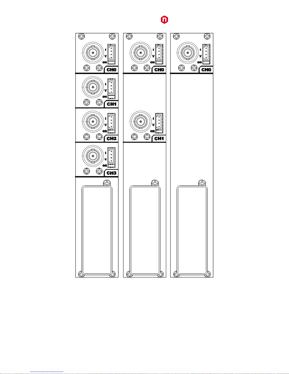
Front and back panel
Fig. 3: Mod. N1419 series front panel (std., A, B)
CAEN
Electronic Instrumentation
UM2619 – N1419 User Manual
9
Fig. 4: Mod. N1419 series back panel (std., A, B)

CAEN
Electronic Instrumentation
UM2619 – N1419 User Manual
10
Front panel connections
Local control section
Fig. 5: Local control panel
NAME:
TYPE:
FUNCTION:
MONITOR
1” OLED DISPLAY (96x64)
Local settings monitoring
TUNE
ROTARY SWITCH
Parameter and Mode setting
Channel control section
Fig. 6: Channel control panel and Kill scheme
NAME:
TYPE:
FUNCTION:
HV_EN/OFF/KILL
3 POS. SWITCH
Channel Enable and turning OFF/KILL
ON
RED LED
HV On enabled
REMOTE KILL
AMP 280370-2
The channel is KILLED either as the +/- contacts are open or as a
+4÷6Vdc voltage is fed to pin -
+
GREEN LED
Positive polarity
-
YELLOW LED
Negative polarity

CAEN
Electronic Instrumentation
UM2619 – N1419 User Manual
11
HV Status control section
Fig. 7: N1419 HV Status control panel
NAME:
TYPE:
SIGNAL:
FUNCTION:
ON
RED LED
HV On enabled (at least one channel ON)
ALARM
RED LED/ AMP 280371-2.
Out
Alarm status signalled (active LOW)
INTERLOCK
RED LED/ AMP 280371-2
In
Interlock signal
Alarm signal
Fig. 8: N1419 ALARM electrical scheme
As an Alarm condition is detected (see p. 31 and 33) pins 2 and 3 (- and +) are closed; the contact can be used to
switch an external device supplied by an external source, otherwise the VB and GND references can be used to
provide a TTL compatible level on pin 2 and 3.
In the first case (externally supplied device) the maximum allowed ratings are:
• Maximum voltage between + and -: 12V
• Maximum sink current across + and -: 100mA
In the latter case, in order to produce a TTL compatible Alarm Out, pin 3 (+) must be connected with pin 4 (VB) and
pin 1 (GND) with pin 2 (-); see the diagram below:
Fig. 9: N1419 ALARM TTL configured
Interlock signal
Fig. 10: N1419 INTERLOCK electrical scheme
A schematic diagram of the Interlock input is shown in the figure above, where the diode is part of optocoupler
stage.
Interlock means that channels are hardware disabled. The interlock operation is explained by the following table:

CAEN
Electronic Instrumentation
UM2619 – N1419 User Manual
12
Table 3: Interlock operation
CONFIGURATION ↓
INTERLOCK MODE (p.15) →
OPEN
CLOSE
leave contact open
INTERLOCK
ENABLED
voltage level (0÷1V, ~5mA current) between pin 2 and pin 3
INTERLOCK
ENABLED
short circuit pin 1 with pin 2, and pin 3 with pin 4
ENABLED
INTERLOCK
voltage level (4÷6V, ~5mA current) between pin 2 and pin 3
ENABLED
INTERLOCK
The front panel Interlock LED is ON when the INTERLOCK is enabled; as INTERLOCK is enabled, channels are turned
off at the fastest available rate, regardless the RAMP DOWN setting.
Remote communication control section
Fig. 11: Remote communication control and RS485 I/O – RS232 IN electrical scheme
NAME:
TYPE:
FUNCTION:
IN
AMP 280371-2
RS485 Input1; adaptable to RS232 standard
OUT
AMP 280371-2
RS485 Output
USB
B TYPE USB
USB2.0 compliant realized via USB ↔ RS232 FT232BM converter
1
RS 485 Serial Port Interface allows to control up to 32 modules connected by a twisted pair cable; the first and last modules must be terminated,
see p.36.
 Loading...