

Page 1
CAEN
Tools
for Discovery
Electronic Instrumentation
Es
UM2619
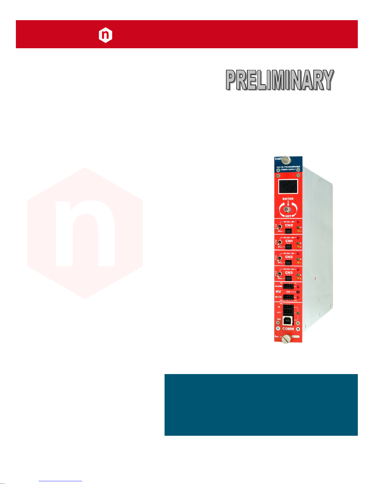
N1419 User Manual
Rev. 2 - 22 March 2013
Page 2

Purpose of this Manual
This document is the N1419 User's Manual; it contains information about the installation, the configuration and the
use of the Power Supply System.
Change Document Record
Date
Revision
Changes
30 May 2012
Rev. 0
Internal use
30 November 2012
Rev. 1
Preliminary
22 March 2013
Rev. 2
Polarity change instructions update
Symbols, abbreviated terms and notation
T.B.D.
Reference Documents
T.B.D.
Disclaimer
No part of this manual may be reproduced in any form or by any means, electronic, mechanical, recording, or
otherwise, without the prior written permission of CAEN SpA.
CAEN will repair or replace any product within the guarantee period if the Guarantor declares that the product is
defective due to workmanship or materials and has not been caused by mishandling, negligence on behalf of the User,
accident or any abnormal conditions or operations.
CAEN declines all responsibility for damages or injuries caused by an improper use of the Modules due to negligence on
behalf of the User. It is strongly recommended to read thoroughly the CAEN User's Manual before any kind of
operation. CAEN reserves the right to change partially or entirely the contents of this Manual at any time and without
giving any notice.
Disposal of the Product The product must never be dumped in the Municipal Waste. Please check your local regulations
for disposal of electronics products.
Made In Italy : We stress the fact that all the boards are made in Italy because in this globalized world, where getting
the lowest possible price for products sometimes translates into poor pay and working conditions for the people who
make them, at least you know that who made your board was reasonably paid and worked in a safe environment. (this
obviously applies only to the boards marked "made in italy", we cannot attest to the manufacturing process of "third
party" boards).
Page 3

CAEN
Electronic Instrumentation
UM2619 – N1419 User Manual
3
Index
1. General description ............................................................................................................ 5
Overview ................................................................................................................................................................... 5
2. Technical specifications ...................................................................................................... 6
Packaging .................................................................................................................................................................. 6
Power requirements ................................................................................................................................................. 6
Front and back panel ................................................................................................................................................ 8
Front panel connections ......................................................................................................................................... 10
Local control section ............................................................................................................................................................10
Channel control section .......................................................................................................................................................10
HV Status control section .....................................................................................................................................................11
Alarm signal ...............................................................................................................................................................................11
Interlock signal ...........................................................................................................................................................................11
Remote communication control section ..............................................................................................................................12
Rear panel connections .......................................................................................................................................... 13
HV Channel Output ..............................................................................................................................................................13
Imon Zoom .............................................................................................................................................................. 13
Technical specifications table ................................................................................................................................. 14
3. Operating modes .............................................................................................................. 15
Programmable parameters ..................................................................................................................................... 15
Boards parameters ...............................................................................................................................................................15
Channel settings ...................................................................................................................................................................16
Local Control ........................................................................................................................................................... 17
HV connection ......................................................................................................................................................................17
Module settings ...................................................................................................................................................................18
Channel settings ...................................................................................................................................................................19
Group Settings ...........................................................................................................................................................................21
Smileys .......................................................................................................................................................................................23
Current monitor offset calibration ......................................................................................................................... 23
Remote Control ...................................................................................................................................................... 24
Serial Links............................................................................................................................................................................24
USB communication ..................................................................................................................................................................24
RS232 communication ...............................................................................................................................................................24
RS485 communication ...............................................................................................................................................................25
Ethernet communication ...........................................................................................................................................................25
Communication Control .......................................................................................................................................................26
Remote Control: Main Menu .....................................................................................................................................................26
Remote Control: General Menu ................................................................................................................................................27
Remote Control: Channels Menu ..............................................................................................................................................27
Remote Control: firmware upgrade...........................................................................................................................................28
Remote Control: format EEPROM .............................................................................................................................................29
Remote Control: Current offset calibration ...............................................................................................................................29
USB - RS485 Communication Protocol ................................................................................................................... 30
Command Format ................................................................................................................................................................30
Format of response string ....................................................................................................................................................30
MONITOR commands related to the Channels ....................................................................................................................30
Meaning of STATUS bits (value read in decimal Format) ...........................................................................................................31
MONITOR commands related to the module ......................................................................................................................32
Meaning of Board Alarm bits .....................................................................................................................................................33
SET commands related to the Channels ...............................................................................................................................33
SET commands related to the module .................................................................................................................................33
4. Internal Settings ............................................................................................................... 34
Polarity selection .................................................................................................................................................... 34
Internal switches ..................................................................................................................................................... 36
Local Bus termination ..........................................................................................................................................................36
RS485 – RS232 conversion ...................................................................................................................................................36
List of Figures
Fig. 1: Mod. 1419 series ...........................................................................................................................................................................5
Fig. 2: Backplane NIM connector .............................................................................................................................................................7
Page 4

CAEN
Electronic Instrumentation
UM2619 – N1419 User Manual
4
Fig. 3: Mod. N1419 series front panel (std., A, B) ....................................................................................................................................8
Fig. 4: Mod. N1419 series back panel (std., A, B) .....................................................................................................................................9
Fig. 5: Local control panel ......................................................................................................................................................................10
Fig. 6: Channel control panel and Kill scheme .......................................................................................................................................10
Fig. 7: N1419 HV Status control panel ...................................................................................................................................................11
Fig. 8: N1419 ALARM electrical scheme ................................................................................................................................................11
Fig. 9: N1419 ALARM TTL configured ....................................................................................................................................................11
Fig. 10: N1419 INTERLOCK electrical scheme ........................................................................................................................................11
Fig. 11: Remote communication control and RS485 I/O – RS232 IN electrical scheme .........................................................................12
Fig. 12: HV Channel panel and test point electrical scheme ..................................................................................................................13
Fig. 13: Welcome screen........................................................................................................................................................................17
Fig. 14: Channel OFF status screen ........................................................................................................................................................17
Fig. 15: Channel ON status screen .........................................................................................................................................................17
Fig. 16: Channel KILL status screen ........................................................................................................................................................17
Fig. 17: Mode settings status screen .....................................................................................................................................................18
Fig. 18: Mode settings access screen .....................................................................................................................................................18
Fig. 19: Mode settings edit screen .........................................................................................................................................................18
Fig. 20: Channel settings edit screen .....................................................................................................................................................19
Fig. 21: Channel VSET select screen .......................................................................................................................................................19
Fig. 22: Channel VSET access screen ......................................................................................................................................................19
Fig. 23: Channel VSET digit selection screen ..........................................................................................................................................19
Fig. 24: Channel VSET digit access screen ..............................................................................................................................................20
Fig. 25: Channel VSET digit adjust screen ..............................................................................................................................................20
Fig. 26: Channel VSET digit confirm screen ............................................................................................................................................20
Fig. 27: Channel VSET confirm screen....................................................................................................................................................20
Fig. 28: Channel VSET de-select screen .................................................................................................................................................20
Fig. 29: Channel KILL screen ..................................................................................................................................................................21
Fig. 30: Channel EXIT screen ..................................................................................................................................................................21
Fig. 31: Group selection .........................................................................................................................................................................21
Fig. 32: Group active ..............................................................................................................................................................................21
Fig. 33: Group VSET access screen .........................................................................................................................................................22
Fig. 34: Group VSET digit selection screen .............................................................................................................................................22
Fig. 35: Group Channel VSET digit access screen ...................................................................................................................................22
Fig. 36: Group VSET digit adjust screen .................................................................................................................................................22
Fig. 37: Group VSET digit confirm screen ...............................................................................................................................................22
Fig. 38: Channel VSET de-select screen .................................................................................................................................................23
Fig. 39: Group EXIT screen .....................................................................................................................................................................23
Fig. 40: USB communication diagram ....................................................................................................................................................24
Fig. 41: RS232 communication diagram ................................................................................................................................................24
Fig. 42: RS485 communication diagram ................................................................................................................................................25
Fig. 43: Ethernet communication diagram ............................................................................................................................................25
Fig. 44: RS232 port cable adapter ..........................................................................................................................................................26
Fig. 45: Main Menu ................................................................................................................................................................................26
Fig. 46: Board Status Menu ...................................................................................................................................................................27
Fig. 47: Channels Menu .........................................................................................................................................................................27
Fig. 48: PC keyboard ..............................................................................................................................................................................27
Fig. 49: Channels group setting .............................................................................................................................................................28
Fig. 50: Firmware Upgrade Menu/1 ......................................................................................................................................................28
Fig. 51: Firmware Upgrade Menu/2 ......................................................................................................................................................28
Fig. 52: Format EEPROM Menu .............................................................................................................................................................29
Fig. 53: Current offset calibration warning ............................................................................................................................................29
Fig. 54: Current offset calibration VSET selection ..................................................................................................................................29
Fig. 55: Current offset calibration confirmation ....................................................................................................................................30
Fig. 56: Side cover removal instructions ................................................................................................................................................34
Fig. 57: Polarity selection instructions ..................................................................................................................................................35
Fig. 58: Dip switch position ....................................................................................................................................................................36
List of Tables
Table 1: Available items ...........................................................................................................................................................................5
Table 2: Power requirements ..................................................................................................................................................................6
Table 3: Interlock operation ..................................................................................................................................................................12
Table 4: Mod. N1419 Channel technical specifications .........................................................................................................................14
Table 5: Smileys list ...............................................................................................................................................................................23
Page 5
CAEN
Electronic Instrumentation
UM2619 – N1419 User Manual
5
1. General description
Overview
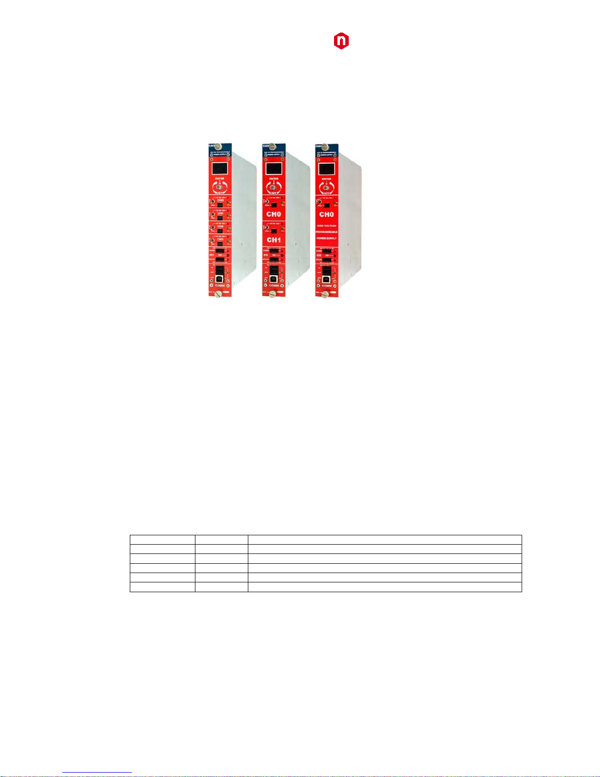
Fig. 1: Mod. 1419 series
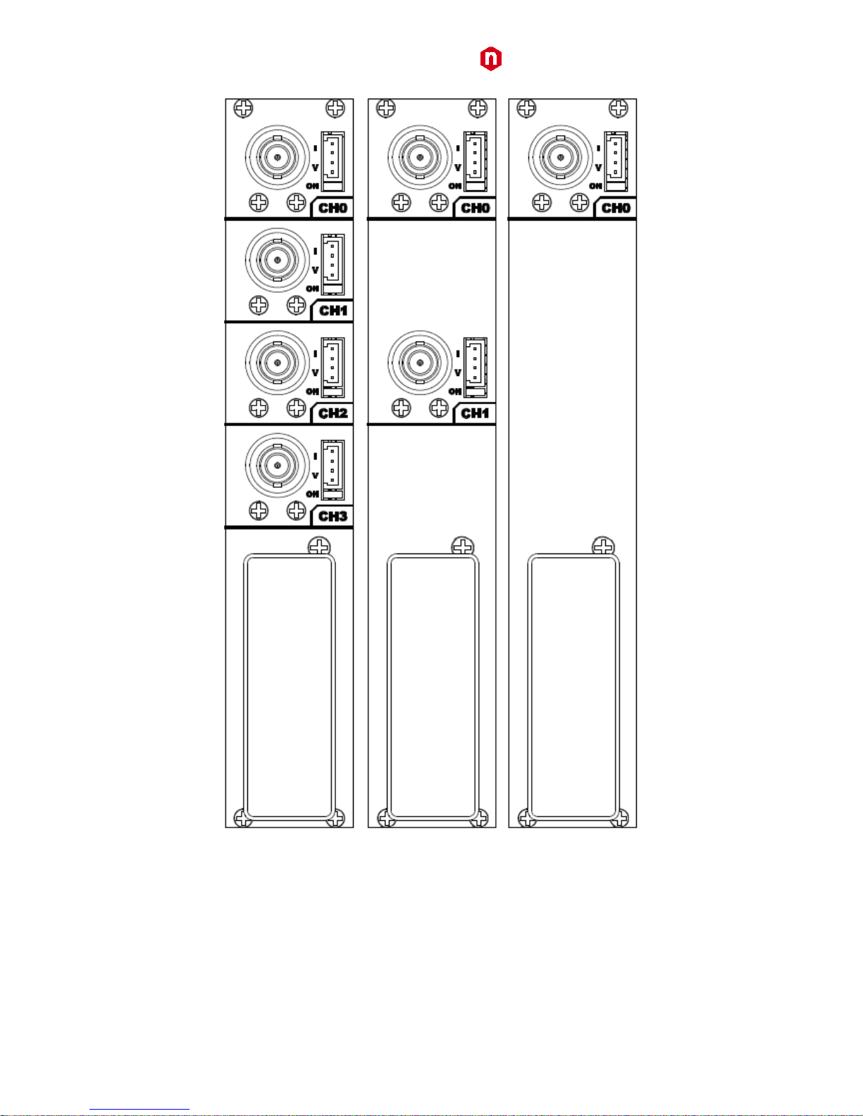
The Mod. N1419 provides 4 independent High Voltage channels in a single width NIM mechanics. Two and one
channel versions (N1419A and N1419B) are also available.
Each channel can provide a ±500V / 200 µA max output.
Channels have common floating return (common return insulated from the crate ground); HV outputs are delivered
through SHV connectors.
The HV output RAMP-UP and RAMP-DOWN rates may be selected independently for each channel in the range
1÷50 V/s in 1 V/s steps.
Safety features include:
• OVERVOLTAGE and UNDERVOLTAGE warning when the output voltage differs from the programmed value by
more than 2% of set value (minimum 1V).
• Programmable VMAX protection limit
• OVERCURRENT detection: if a channel tries to draw a current larger than its programmed limit, it enters TRIP
status, keeping the maximum allowed value for a programmable time (TRIP), before being switched off
• Channels can be enabled or disabled individually through the Interlock logic.
Module control can take place either locally, assisted by a Graphic color display or remotely, via USB, RS232 or
RS485; the RS485 port allows to build a N1419s’ daisy chain network (up to 32 modules); in this case the SW1470
Control Software is necessary (see download section on www.caen.it).
The Mod. A1480 is an optional DC Input Power Equalizer which allows to use a different input power distribution on
the N147x modules.
Table 1: Available items
Code
Item
Description
WN1419XAAAAA
N1419
4 Channels, local & remote control, NIM HV Power Supply (±500V, 200uA, 10nA res.)
WN1419AXAAAA
N1419A
2 Channels, local & remote control, NIM HV Power Supply (±500V, 200uA, 10nA res.)
WN1419BXAAAA
N1419B
1 Channel, local & remote control, NIM HV Power Supply (±500V, 200uA, 10nA res.)
WA1480XAAAAA
A1480
DC Power Input Equalizer for N147X Family
WPERS0147001
Customization
Imon Zoom x10
Page 6
CAEN
Electronic Instrumentation
UM2619 – N1419 User Manual
6
2. Technical specifications
Packaging
The Mod. N1419 boards are housed in a single width NIM modules.
Power requirements
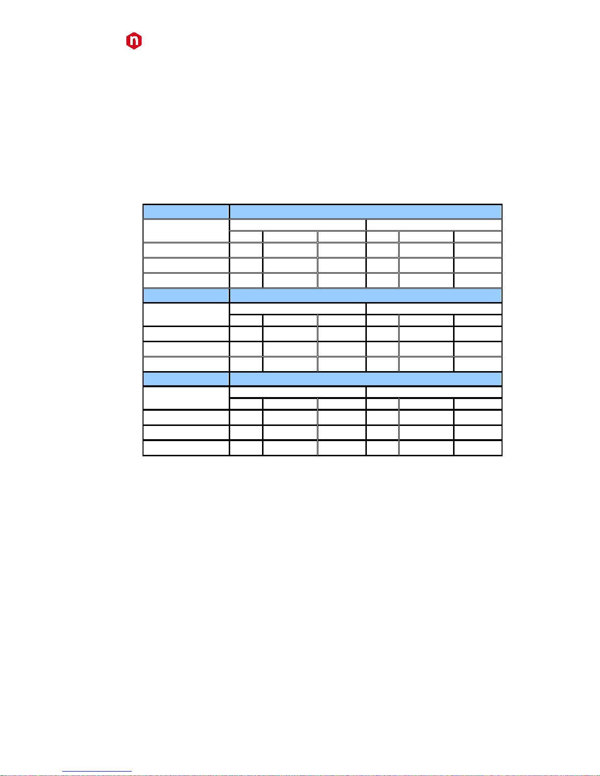
Table 2: Power requirements
Board type
N
1419
Channel configuration
without A1480
with A1480
N° ch ON
Current (± 12V)
Current (±6V)
n° ch ON
Current (± 12V)
Current (±6V)
3
00V/200µA
4 CH T.B.D.
none
4 CH
T.B.D T.B.D 5
00V/20µA
4 CH T.B.D
none
4 CH
T.B.D T.B.D 5
00V/200µA
4 CH T.B.D
none
4 CH
T.B.D T.B.D
Board type
N
1419A
Channel configuration
without A1480
with A1480
N° ch ON
Current (± 12V)
Current (±6V)
n° ch ON
Current (± 12V)
Current (±6V)
3
00V/200µA
2 CH T.B.D
none
2 CH
T.B.D T.B.D 5
00V/20µA
2 CH T.B.D
none
2 CH
T.B.D
T.B.D
5
00V/200µA
2 CH T.B.D
none
2 CH
T.B.D T.B.D
Board type
N
1419B
Channel configuration
without A1480
with A1480
N° ch ON
Current (± 12V)
Current (±6V)
n° ch ON
Current (± 12V)
Current (±6V)
3
00V/200µA
1 CH T.B.D
none
1 CH
T.B.D T.B.D 5
00V/20µA
1 CH T.B.D
none
1 CH
T.B.D T.B.D 5
00V/200µA
1 CH T.B.D
none
1 CH
T.B.D T.B.D
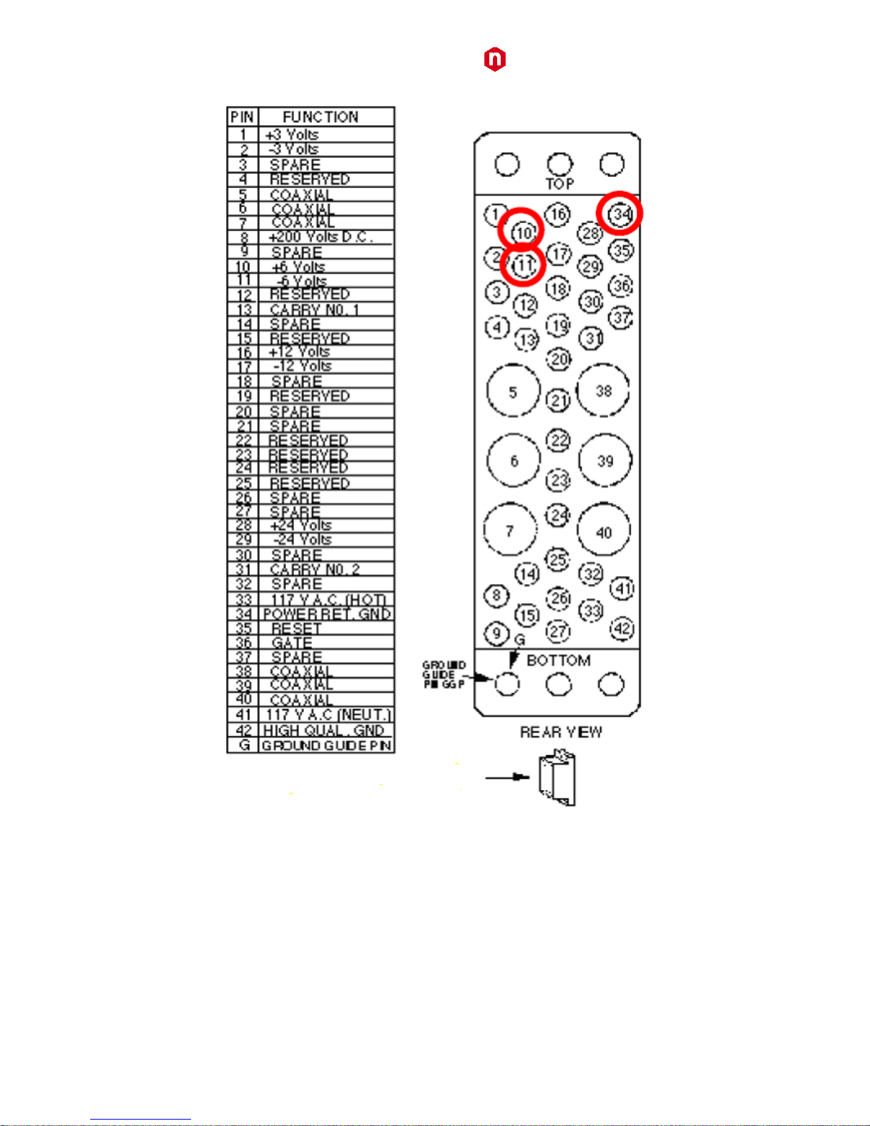
WARNING: if the A1480 is not installed, ±6V power supplies are not required and power pins 10 and 11 on the
backplane NIM connector are not installed (see Fig. 2).
Page 7
CAEN
Electronic Instrumentation
UM2619 – N1419 User Manual
7
Fig. 2: Backplane NIM connector
Page 8

CAEN
Electronic Instrumentation
UM2619 – N1419 User Manual
8
Front and back panel
Fig. 3: Mod. N1419 series front panel (std., A, B)
Page 9
CAEN
Electronic Instrumentation
UM2619 – N1419 User Manual
9
Fig. 4: Mod. N1419 series back panel (std., A, B)
Page 10

CAEN
Electronic Instrumentation
UM2619 – N1419 User Manual
10
Front panel connections
Local control section
Fig. 5: Local control panel
NAME:
TYPE:
FUNCTION:
MONITOR
1” OLED DISPLAY (96x64)
Local settings monitoring
TUNE
ROTARY SWITCH
Parameter and Mode setting
Channel control section
Fig. 6: Channel control panel and Kill scheme
NAME:
TYPE:
FUNCTION:
HV_EN/OFF/KILL
3 POS. SWITCH
Channel Enable and turning OFF/KILL
ON
RED LED
HV On enabled
REMOTE KILL
AMP 280370-2
The channel is KILLED either as the +/- contacts are open or as a
+4÷6Vdc voltage is fed to pin -
+
GREEN LED
Positive polarity
-
YELLOW LED
Negative polarity
Page 11

CAEN
Electronic Instrumentation
UM2619 – N1419 User Manual
11
HV Status control section
Fig. 7: N1419 HV Status control panel
NAME:
TYPE:
SIGNAL:
FUNCTION:
ON
RED LED
HV On enabled (at least one channel ON)
ALARM
RED LED/ AMP 280371-2.
Out
Alarm status signalled (active LOW)
INTERLOCK
RED LED/ AMP 280371-2
In
Interlock signal
Alarm signal
Fig. 8: N1419 ALARM electrical scheme
As an Alarm condition is detected (see p. 31 and 33) pins 2 and 3 (- and +) are closed; the contact can be used to
switch an external device supplied by an external source, otherwise the VB and GND references can be used to
provide a TTL compatible level on pin 2 and 3.
In the first case (externally supplied device) the maximum allowed ratings are:
• Maximum voltage between + and -: 12V
• Maximum sink current across + and -: 100mA
In the latter case, in order to produce a TTL compatible Alarm Out, pin 3 (+) must be connected with pin 4 (VB) and
pin 1 (GND) with pin 2 (-); see the diagram below:
Fig. 9: N1419 ALARM TTL configured
Interlock signal
Fig. 10: N1419 INTERLOCK electrical scheme
A schematic diagram of the Interlock input is shown in the figure above, where the diode is part of optocoupler
stage.
Interlock means that channels are hardware disabled. The interlock operation is explained by the following table:
Page 12

CAEN
Electronic Instrumentation
UM2619 – N1419 User Manual
12
Table 3: Interlock operation
CONFIGURATION ↓
INTERLOCK MODE (p.15) →
OPEN
CLOSE
leave contact open
INTERLOCK
ENABLED
voltage level (0÷1V, ~5mA current) between pin 2 and pin 3
INTERLOCK
ENABLED
short circuit pin 1 with pin 2, and pin 3 with pin 4
ENABLED
INTERLOCK
voltage level (4÷6V, ~5mA current) between pin 2 and pin 3
ENABLED
INTERLOCK
The front panel Interlock LED is ON when the INTERLOCK is enabled; as INTERLOCK is enabled, channels are turned
off at the fastest available rate, regardless the RAMP DOWN setting.
Remote communication control section
Fig. 11: Remote communication control and RS485 I/O – RS232 IN electrical scheme
NAME:
TYPE:
FUNCTION:
IN
AMP 280371-2
RS485 Input1; adaptable to RS232 standard
OUT
AMP 280371-2
RS485 Output
USB
B TYPE USB
USB2.0 compliant realized via USB ↔ RS232 FT232BM converter
1
RS 485 Serial Port Interface allows to control up to 32 modules connected by a twisted pair cable; the first and last modules must be terminated,
see p.36.
Page 13
CAEN
Electronic Instrumentation
UM2619 – N1419 User Manual
13
Rear panel connections
HV Channel Output
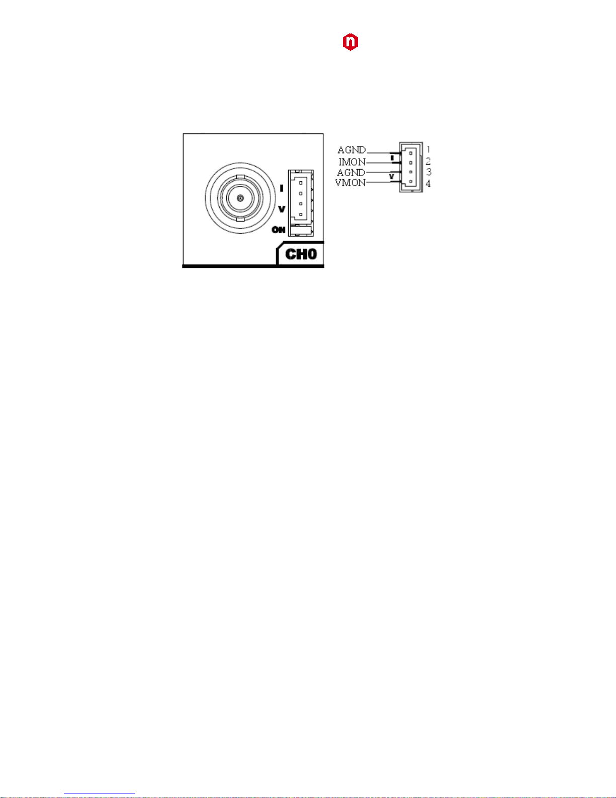
Fig. 12: HV Channel panel and test point electrical scheme
NAME:
TYPE:
FUNCTION:
MON
AMP 280371-2
Vout/Iout Test point
OUT
SHV
HV Channel Output
The test points allow to monitor the Channel Output Voltage and Current according to the following conversion:
VMON: Voltage level (1V = 136 V ±1% readout; same polarity as channel)
IMON: Voltage level (1V = 44 µA ±3% readout; positive, 0÷5 V range)
Imon Zoom
Imon Zoom is an optional feature that allows to monitor the channel current with an increased resolution (10x) in
the 0 – 20 µA range; if the Imon Zoom is installed, by selecting Imon Range = LOW (see p.16), the output current is
monitored with 0.5nA resolution (instead of 5 nA), in the 0 – 20 µA range. It is important to notice that, if Imon
Range = LOW is selected, and the channel draws a current larger than 20 µA, then Overcurrent is signalled.
Page 14
CAEN
Electronic Instrumentation
UM2619 – N1419 User Manual
14
Technical specifications table
Table 4: Mod. N1419 Channel technical specifications
Output channels:
Positive or Negative Polarity (requires internal setting, see p. Errore. Il segnalibro non è definito.)
Output ranges:
500 V / 200µA
Max. Ch. Output Power:
100 mW
Vset / Vmon Resolution:
10 mV
Iset / Imon Resolution2:
If IMON RANGE = High is selected resolution is 5 nA
If IMON RANGE = Low is selected resolution is 0.5 nA
Vmax:
0 ÷ 510 V
Absolute maximum HV level that the channel is allowed to reach, independently from the preset value
Vset. Output voltage cannot exceed the preset value Vmax. The accuracy is 1 % ± 0.5 V
Vmax resolution:
± 0.1 V
Alarm output:
Open collector, 100 mA maximum sink current
Interlock input:
LOW: <1V; current~5mA; HIGH: 4÷6 V
Ramp Up/Down:
1÷50 Volt/s, 1 Volt/s step
Trip:
Max. time an "overcurrent" is allowed to last (seconds). A channel in "overcurrent" works as a current
generator; output voltage varies in order to keep the output current lower than the programmed
value. "Overcurrent" lasting more than set value (1 to 9999) causes the channel to "trip". Output
voltage will drop to zero either at the Ramp-down rate or at the fastest available rate, depending on
Power Down setting; in both cases the channel is put in the OFF state. If trip= INFINITE, "overcurrent"
lasts indefinitely.
TRIP range: 0 ÷ 999.9 s; 1000 s = Infinite. Step = 0.1 s
Vmon vs. Vout Accuracy: 3
±0.02% of read value ±0.2V
Vset vs. Vmon Accuracy:
4
±0.02% of read value ±0.2V
Imon vs. Iout Accuracy: 4
If IMON RANGE = High : ±2% of read value ±20nA
If IMON RANGE = Low: ±2% of read value ±2nA
Iset vs. Imon Accuracy: 4
If IMON RANGE = High : ±2% of read value ±30nA
If IMON RANGE = Low: ±2% of read value ±3nA
Voltage Ripple:4
band width
typical
maximum
10Hz÷100Hz
<5mVpp
<5mVpp
100Hz÷100MHz
<5mVpp
<5mVpp
Humidity range:
0 ÷ 80%
Operating temperature:
0 ÷ 45°C
Storage temperature:
-10 ÷ 70°C
Vout / Temperature coefficient:
max. 50ppm / °C
Vout /voltage coefficient:
max 2ppm/mV
Imon / Temperature coefficient:
max 100ppm/C°; max 300ppm/C° with Imon X10 zoom (optional)
Long term stability Vout vs. Vset:
± 0.02% (after one week @ constant temperature)
2
The module is calibrated by introducing a positive offset on the current monitor, see details p. 24
3
From 10% to 90% of Full Scale Range
4
Measured with: 1m cable length; 2nF capacitance
Page 15

CAEN
Electronic Instrumentation
UM2619 – N1419 User Manual
15
3. Operating modes
CAUTION: N1419 MUST BE USED ONLY IN CRATES WITH FORCED COOLING AIR FLOW!
Module control can take place either locally, or remotely, via USB or RS485 (see p. 24).
Programmable parameters
Boards parameters
General board parameters (CONTROL can be operated both in LOCAL and REMOTE mode; other monitor and
settings are allowed in LOCAL mode only; see p.17) include:
Parameter:
Function:
Display:
Power
(Monitor)
Module power supply status
Termination
(Monitor)
Local Bus termination status (ON/OFF)
HV Clock
(Monitor)
Sync clock frequency (200±10 kHz correct value)
Local Bus
Baud Rate
(Monitor/Set)
9600, 19200. 38400, 57600, 115200 Baud
Local Bus
Address
(Monitor/Set)
Local Bus address for remote communication (0÷31)
USB Baud
Rate
(Monitor/Set)
9600, 19200, 38400, 57600, 115200 Baud
INTERLOCK
(Monitor/Set)
CLOSED / OPEN OPERATION (see p.11)
CONTROL
(Monitor/Set)
REMOTE: the module is controlled remotely; local monitor is allowed;
LOCAL/REMOTE switch is enabled
LOCAL: the module is controlled locally; remote monitor is allowed
Page 16

CAEN
Electronic Instrumentation
UM2619 – N1419 User Manual
16
Channel settings
For each channel the following parameters can be programmed and monitored either locally or remotely (see p.24):
Parameter:
Function:
Unit:
Display:
Vmon
High Voltage Monitored value
Volt
Imon
Current Monitored value
µA
V
set
High Voltage programmed value
Volt
I
set
Current Limit programmed value
µA
MaxV
Absolute maximum High Voltage level that the
channel is allowed to reach (see p. 14)
V Ramp-Up
Maximum High Voltage increase rate
V/s Ramp-Down
Maximum High Voltage decrease rate
V/s
Power Down
Power Down mode after channel TRIP
KILL or RAMP
Trip
Maximum time an "overcurrent" is allowed to last
expressed in seconds (see p.14)
s
Imon Range
Current Monitor Zoom 10x (optional)
H or L
Page 17
CAEN
Electronic Instrumentation
UM2619 – N1419 User Manual
17
Local Control
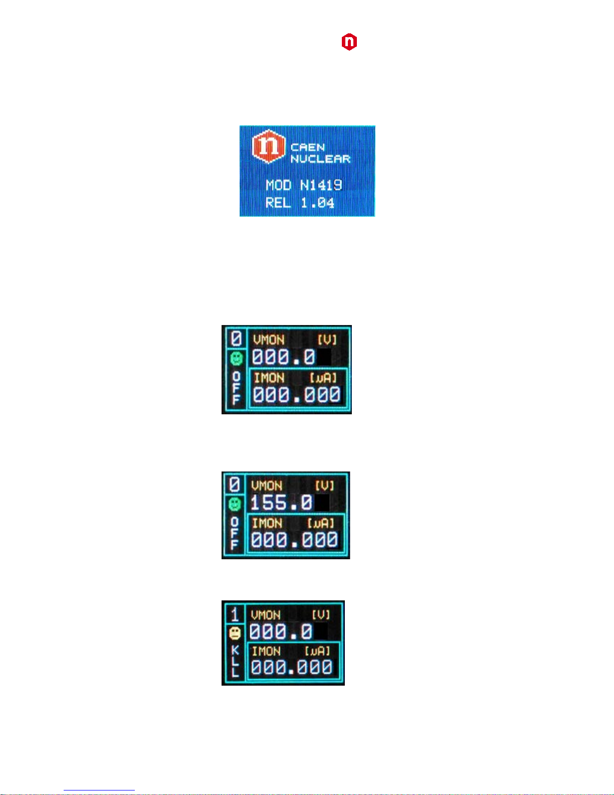
Insert the unit inside a powered NIM crate, and switch it ON. At the power the Display shows for a few seconds the
following screen.
Fig. 13: Welcome screen
At this point the module is ready to be operated locally. The TUNE ROTARY SWITCH (see p.10) is lit up as long as
Local Control is enabled.
HV connection
Verify the channels polarity (polarity setting is explained at p.Errore. Il segnalibro non è definito.) checking that the
polarity LEDs are switched on according to the programmed configuration (see p.10); verify the HV_EN/OFF/KILL 3
POS. SWITCH of each channel is set to OFF; the Display will show the following message in the left lower row:
Fig. 14: Channel OFF status screen
now connect the HV cable linking the outputs to the loads to be supplied and enable the HV outputs switching the
HV_EN/OFF/KILL 3 POS. SWITCH in the HV_EN position; the Display will show the following message in the left
lower row:
Fig. 15: Channel ON status screen
The KILL position of the HV_EN/OFF/KILL 3 POS. SWITCH allows to turn off the module at the fastest available rate;
the Display will show the following message in the left lower row:
Fig. 16: Channel KILL status screen
Page 18
CAEN
Electronic Instrumentation
UM2619 – N1419 User Manual
18
Module settings
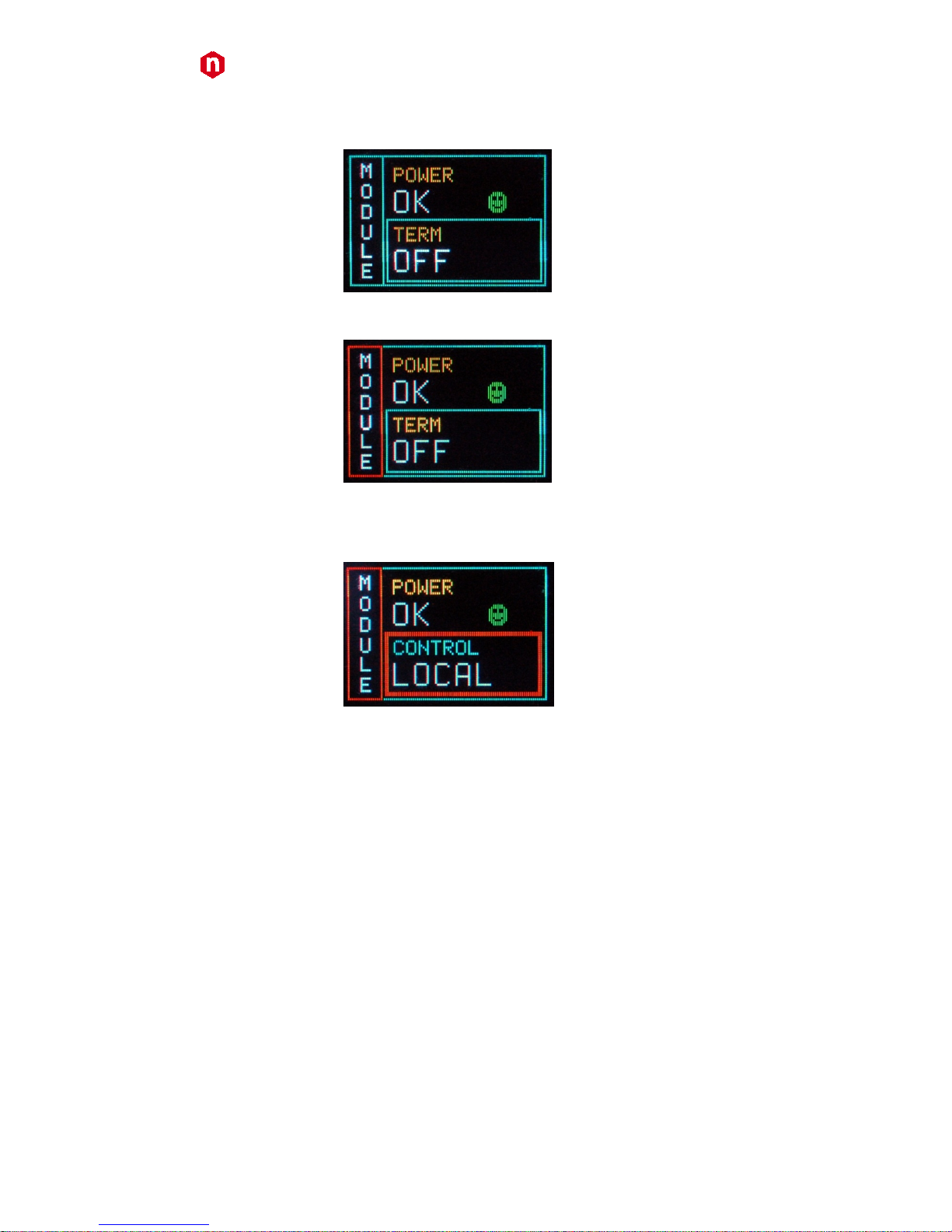
Module settings are general board settings; turn the TUNE ROTARY SWITCH until this screen is shown:
Fig. 17: Mode settings status screen
Push the TUNE ROTARY SWITCH in order to access MODULE parameters; the MODULE frame becomes red:
Fig. 18: Mode settings access screen
The TUNE ROTARY SWITCH allows to select the parameter to be set; turn the ROTARY SWITCH until such parameter
is displayed (for example CONTROL), then select it by pushing the ROTARY SWITCH (the parameter is shown with a
red frame as long as it is active):
Fig. 19: Mode settings edit screen
Select the desired value by turning the TUNE ROTARY SWITCH and confirm it by pushing the switch itself.
Page 19
CAEN
Electronic Instrumentation
UM2619 – N1419 User Manual
19
Channel settings
In order to operate Output Channel settings:
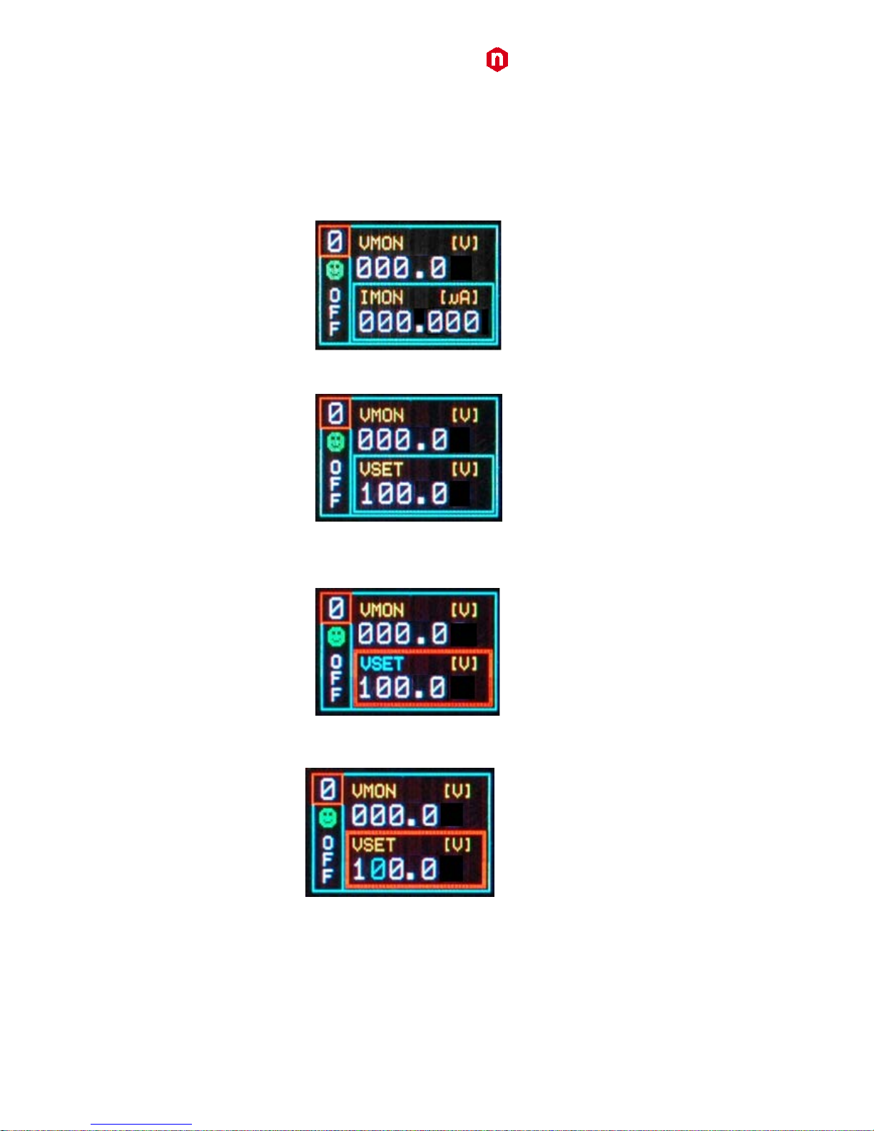
Turn the TUNE ROTARY SWITCH until the channel number to be set is displayed in the left upper row (for example
Channel 0)
Push the TUNE ROTARY SWITCH: at this point the frame of the left upper row (channel number) becomes red and
the channel is selected
Fig. 20: Channel settings edit screen
Turn the TUNE ROTARY SWITCH until the parameter to be set (for example VSET) is displayed in the right lower row
Fig. 21: Channel VSET select screen
Push the TUNE ROTARY SWITCH: at this point the parameter is selected, its frame is shown in red and its name in
blue; it is now possible to change the parameters value
Fig. 22: Channel VSET access screen
Turn the TUNE ROTARY SWITCH until the value digit to be edited is shown in blue, the parameter name in yellow
Fig. 23: Channel VSET digit selection screen
Push the TUNE ROTARY SWITCH: at this point the value digit becomes yellow and can be edited
Page 20
CAEN
Electronic Instrumentation
UM2619 – N1419 User Manual
20
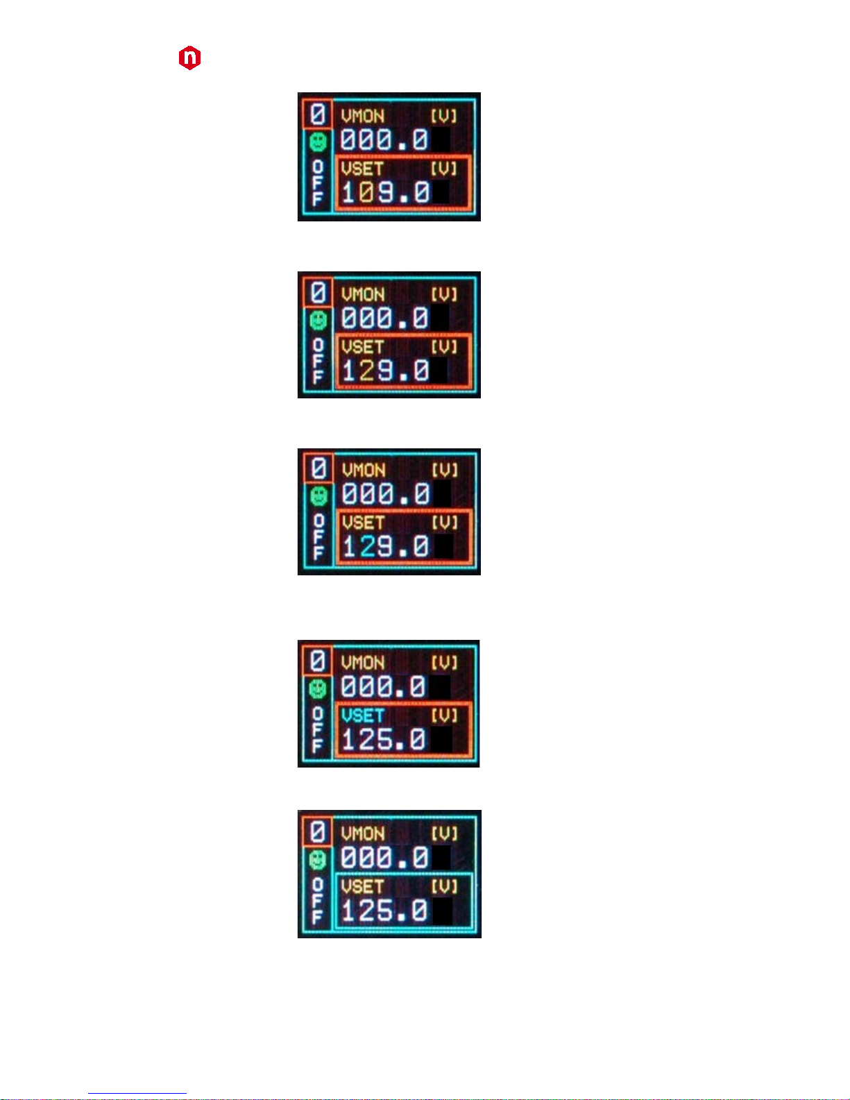
Fig. 24: Channel VSET digit access screen
Turn the TUNE ROTARY SWITCH until the digit reaches the desired value
Fig. 25: Channel VSET digit adjust screen
Confirm it by pushing the TUNE ROTARY SWITCH, the edited digit returns blue
Fig. 26: Channel VSET digit confirm screen
Once all the digits are set to the desired value, turn the TUNE ROTARY SWITCH until the parameter name returns
blue
Fig. 27: Channel VSET confirm screen
Push the TUNE ROTARY SWITCH in order to de-select the parameter, the frame returns to blue
Fig. 28: Channel VSET de-select screen
It is now possible to set another parameter; note that the POWER DOWN and IMRANGE setting has not digits to be
edited, but two options, TRIP/KILL and HIGH/LOW respectively:
Page 21

CAEN
Electronic Instrumentation
UM2619 – N1419 User Manual
21
Fig. 29: Channel KILL screen
In order to access another channel, the EXIT parameter has to be selected
Fig. 30: Channel EXIT screen
Now by turning the TUNE ROTARY SWITCH another channel number to be set can be selected.
If CONTROL MODE (see p.24) is set to REMOTE, the left lower row reports DIS (Disabled), since the channel can be
accessed only via the serial links (see p.24). If the INTERLOCK MODE is changed while one channel is ON, the
channel is turned OFF and the left lower row reports ILK (Interlock); if the channel is OFF, it cannot be turned ON,
until it is enabled according to the Interlock logic (see p.11).
Group Settings5
Group settings allow to broadcast the same parameter value to all channels.
In order to operate Group settings:
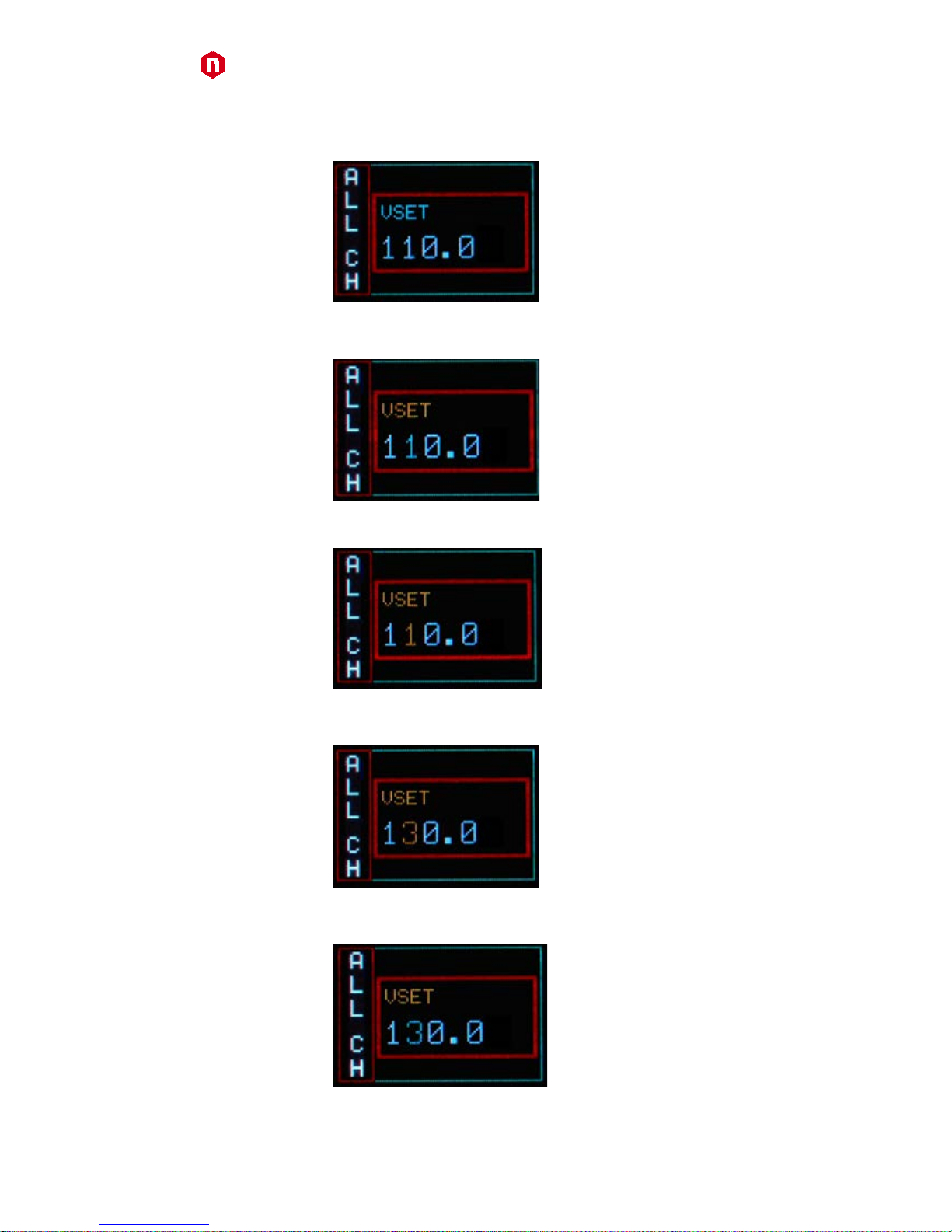
Turn the TUNE ROTARY SWITCH until ALL is displayed in the left column
Fig. 31: Group selection
Push the TUNE ROTARY SWITCH: at this point the frame of the left column becomes red and the GROUP is selected.
Turn the TUNE ROTARY SWITCH until the parameter to be set (for example VSET) is displayed in the right column (all
four channels values).
Fig. 32: Group active
5
Mod. N1419B has not group settings; Mod. N1419A has group settings, 2 channels values are displayed
Page 22
CAEN
Electronic Instrumentation
UM2619 – N1419 User Manual
22
Push the TUNE ROTARY SWITCH: at this point the parameter is selected, its frame is shown in red and its name in
blue (only one value common to all channels; pre-set value is picked from Channel 0); it is now possible to change
the parameters value.
Fig. 33: Group VSET access screen
Turn the TUNE ROTARY SWITCH until the value digit to be edited is shown in blue, the parameter name in yellow
Fig. 34: Group VSET digit selection screen
Push the TUNE ROTARY SWITCH: at this point the value digit becomes yellow and can be edited
Fig. 35: Group Channel VSET digit access screen
Turn the TUNE ROTARY SWITCH until the digit reaches the desired value
Fig. 36: Group VSET digit adjust screen
Confirm it by pushing the TUNE ROTARY SWITCH, the edited digit returns blue
Fig. 37: Group VSET digit confirm screen
Page 23
CAEN
Electronic Instrumentation
UM2619 – N1419 User Manual
23
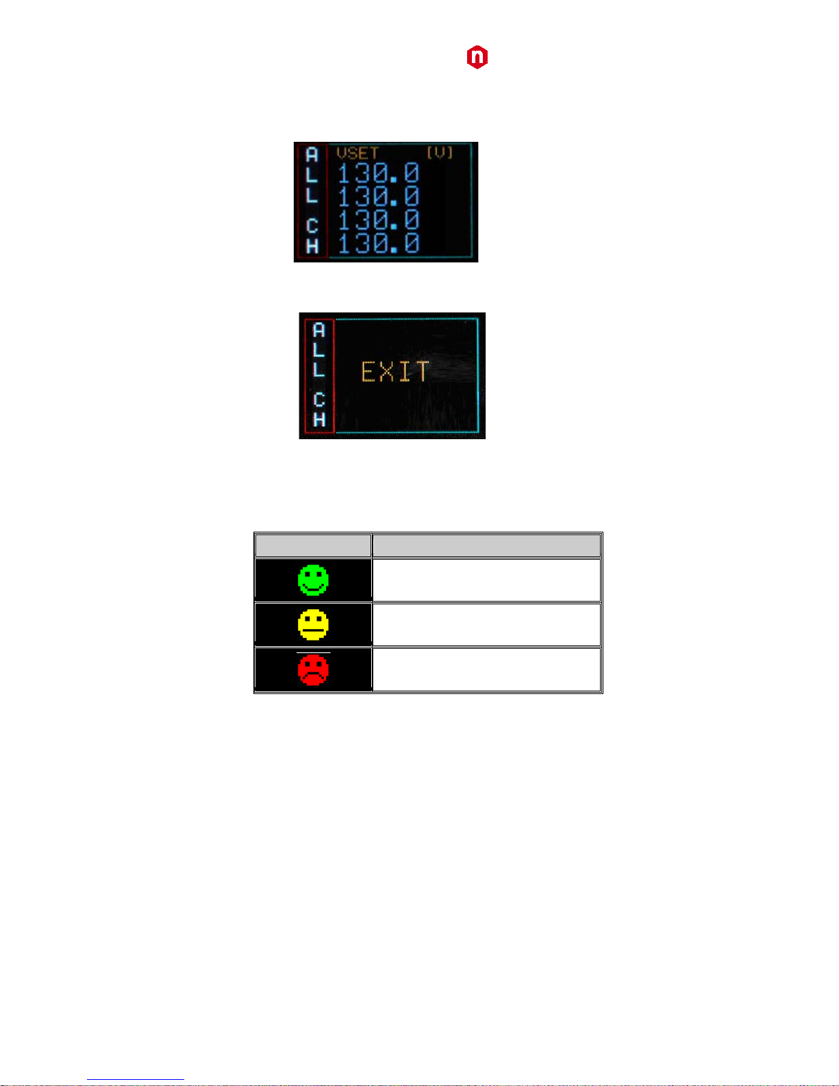
Once all the digits are set to the desired value, turn the TUNE ROTARY SWITCH until the parameter name returns
blue. Push the TUNE ROTARY SWITCH in order to de-select the parameter, the frame returns to blue; when the
parameter is not active, the parameter status of the four channels is shown.
Fig. 38: Channel VSET de-select screen
In order to go to individual channel settings, the EXIT parameter has to be selected
Fig. 39: Group EXIT screen
Smileys
Three types of Smileys in the display indicate:
Table 5: Smileys list
Smiley
Meaning
OK Status
WARNING Status
ALARM Status
Current monitor offset calibration
The module is calibrated by introducing a positive offset on the current monitor. This type of calibration allows to
monitor very low current thus removing possible issues due to components and working temperatures related
negative offsets. The absolute value of delivered current can be quantified by following the steps below:
1) Turn on the module, after a warm-up of about 30 minutes with operating voltage and load disconnected (no
link between N1419 and detectors) then read the monitored current value Imon = I1 (offset)
2) Turn off the channel and connect the load
3) Turn on the channel with the same voltage set as point 1)
4) Wait a few minutes and read again the current value monitor Imon = I2 (offset + Iout)
5) The value of current output is equal to the difference between I2 and I1 (Iout = I2 – I1)
Leakage currents equal to 1 nA / 100 V shall be tolerated; e.g. Vout = 400V, Imon = +6 nA (2nA Offset + 4nA current
leakage/400V). The offset introduced is equal to 20nA for high range and 2nA for low range with output voltage at
10% of full scale and 20 °C temperature.
Page 24
CAEN
Electronic Instrumentation
UM2619 – N1419 User Manual
24
Remote Control
Module control can take place remotely, via USB or RS485; the latter allows to build a N1419s’ daisy chain network.
The CAEN NIM8301 7U 12 Slot Smart Fan Unit 300/600 W Crate allows also to communicate with the module via
Ethernet.
Serial Links
USB communication
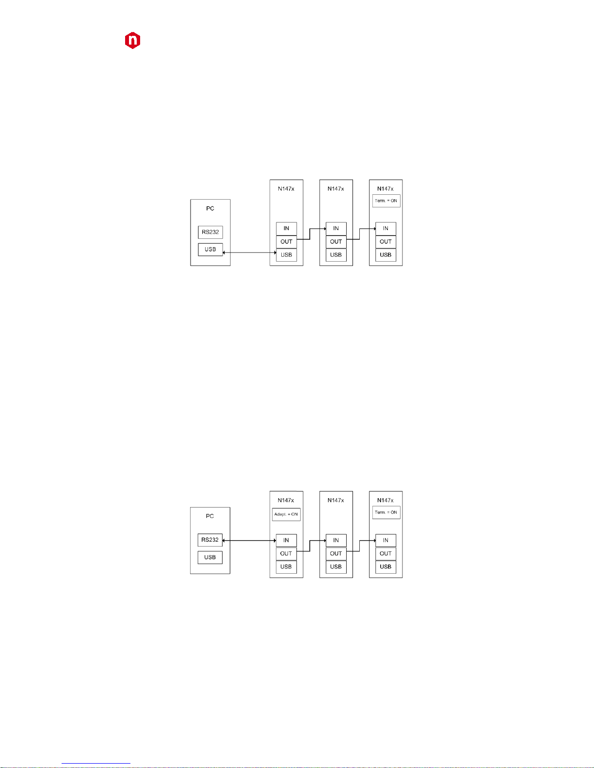
Fig. 40: USB communication diagram
The module is provided with a USB2.0 compliant interface (see p.10). The N1419 can be programmed via PC by
connecting the PC USB port with the N1419 USB B-type port; the featured controller, the FT232BM chip requires
drivers freely available at
www.ftdichip.com (Drivers section); the site also provides installation instructions for all
OS’s (Documents section)
The connection can be performed via terminal emulator, such as HyperTerminal,
configured as follows:
- baud rate 9600 (the same set on the N1419! See p.18)
- Data bits: 8
- Parity: none
- stop bit: 1
- Flow control: Xon Xoff
It is also possible to build a daisy chain of up to 32 N1419’s, with the first module connected to the PC USB port and
the subsequent ones daisy chained through the COMM IN/OUT, as explained on p.30 ; in this case communication
with the chained modules is achieved through the USB - RS485 Communication Protocol, see p.30. All modules must
be assigned a LOCAL BUS ADDRESS (see p.15) different from one another and the last one must be terminated (see
p.36).
RS232 communication
Fig. 41: RS232 communication diagram
In order to control the module via RS232 it is necessary to use the module’s COMM IN port (refer to p.12 for RS232
signals) and to follow adaptation instructions (see p.36).
The connection can be performed via terminal emulator, such as HyperTerminal,
configured as follows:
- baud rate 9600 (the same set on the N1419! See p.15)
- Data bits: 8
- Parity: none
- stop bit: 1
- Flow control: Xon Xoff
Page 25
CAEN
Electronic Instrumentation
UM2619 – N1419 User Manual
25
It is also possible to build a daisy chain of up to 32 N1419’s, with the first module connected to the PC RS232 port
and the subsequent ones daisy chained through the COMM IN/OUT, as explained on p.12; in this case
communication with the chained modules is achieved through the USB - RS485 Communication Protocol . All
modules must be assigned a LOCAL BUS ADDRESS (see p.15) different from one another and the last one must be
terminated (see p.36).
RS485 communication
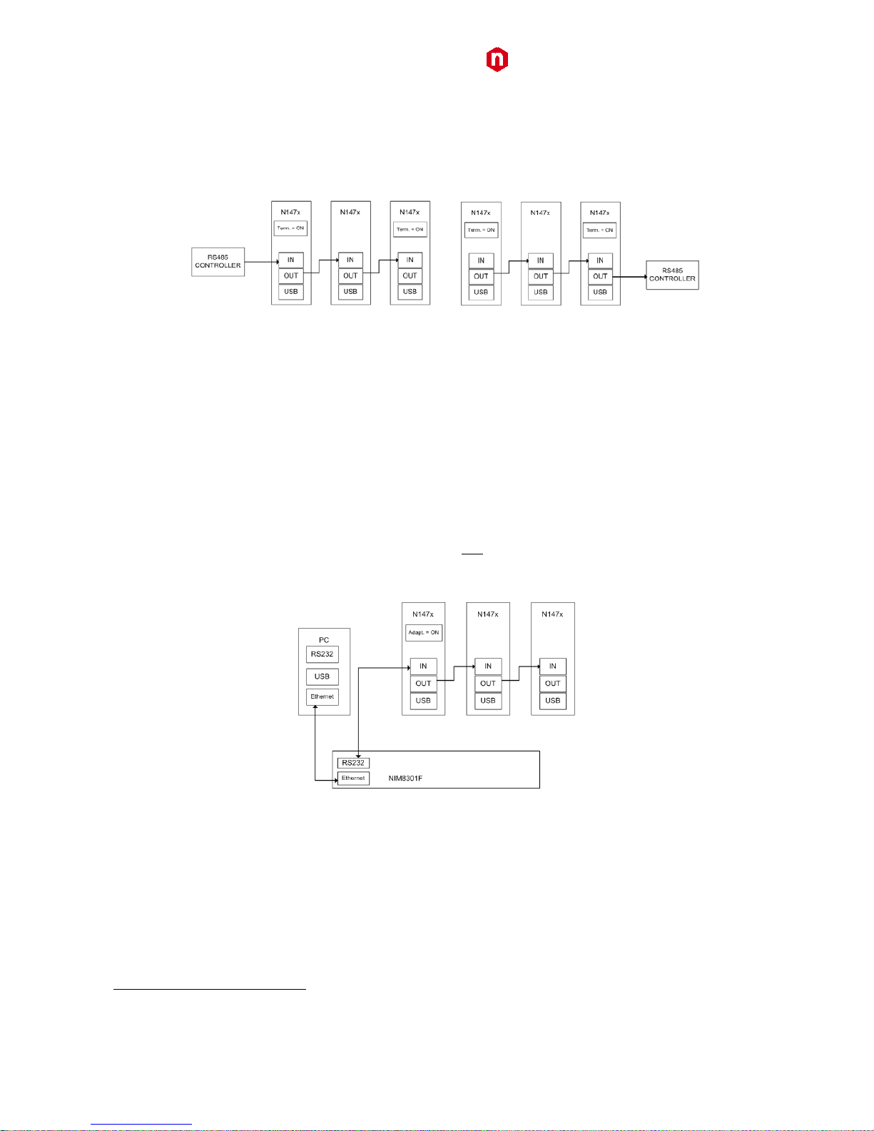
Fig. 42: RS485 communication diagram
The COMM IN / OUT connectors implement a RS485 type LOCAL BUS which allows to build a 32 modules daisy
chain. This can be achieved through the following steps:
− Connect the connector OUT of a module to corresponding the IN connector of the next one
− Assign to each module a different address (LOCAL BUS ADDR); see p. 15
− Ensure that the LOCAL BUS BIT RATE is the same for all modules; see p. 15
− Terminate the first and the last module in the chain (see p.36)
The module control can be done in one of the following ways:
o by connecting a RS485 controller to the first module’s COMM IN port
o by connecting a RS485 controller to the last module’s COMM OUT port
Communication with the chained modules is achieved only through the USB - RS485 Communication Protocol, see
p.24.
Ethernet communication
Fig. 43: Ethernet communication diagram
It is possible to communicate via Ethernet with one or more daisy chained N1419 modules through the NIM8301
Fan Unit
6
. Communication via Ethernet is possible only through the USB - RS485 Communication Protocol. The
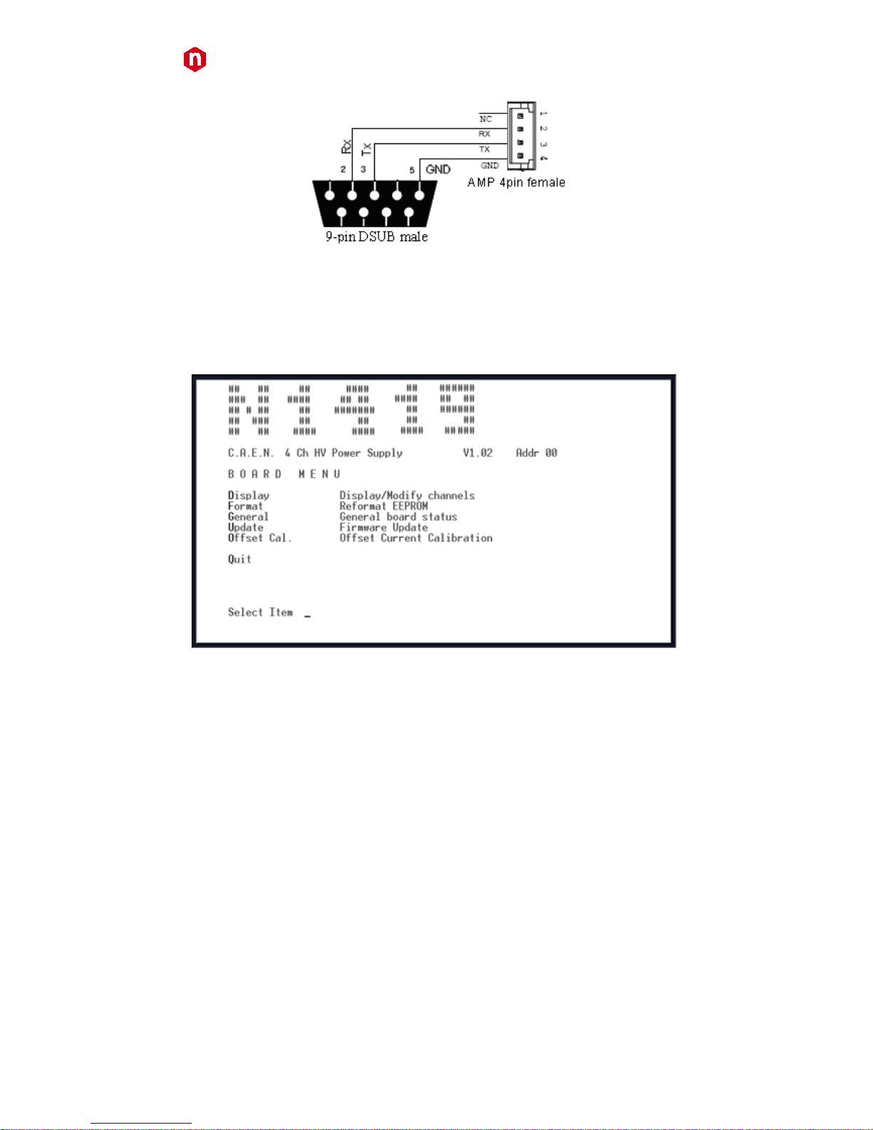
single module or the first module of the daisy chain must be connected to the Fan Unit RS232 port through the
cable adapter (see figure below) connected to the N1419 COMM IN port; SW[200, 201] switch placed on the
Microcontroller board inside the module must be set to Adaptation ON (see p.34).
6
The CAEN Mod. NIM8301 is a 7U (5+2) full size NIM crate (19”-12 slot) available with pluggable 300W and 600W power supplies, ventilated by
pluggable 2U fan unit. Remote control and monitoring take place through CAN bus, Ethernet, USB and RS232 interfaces.
Page 26
CAEN
Electronic Instrumentation
UM2619 – N1419 User Manual
26
Fig. 44: RS232 port cable adapter
Communication Control
In order to launch the communication, type CAEN and then <Enter>
As the communication is established, the Main Menu will be displayed.
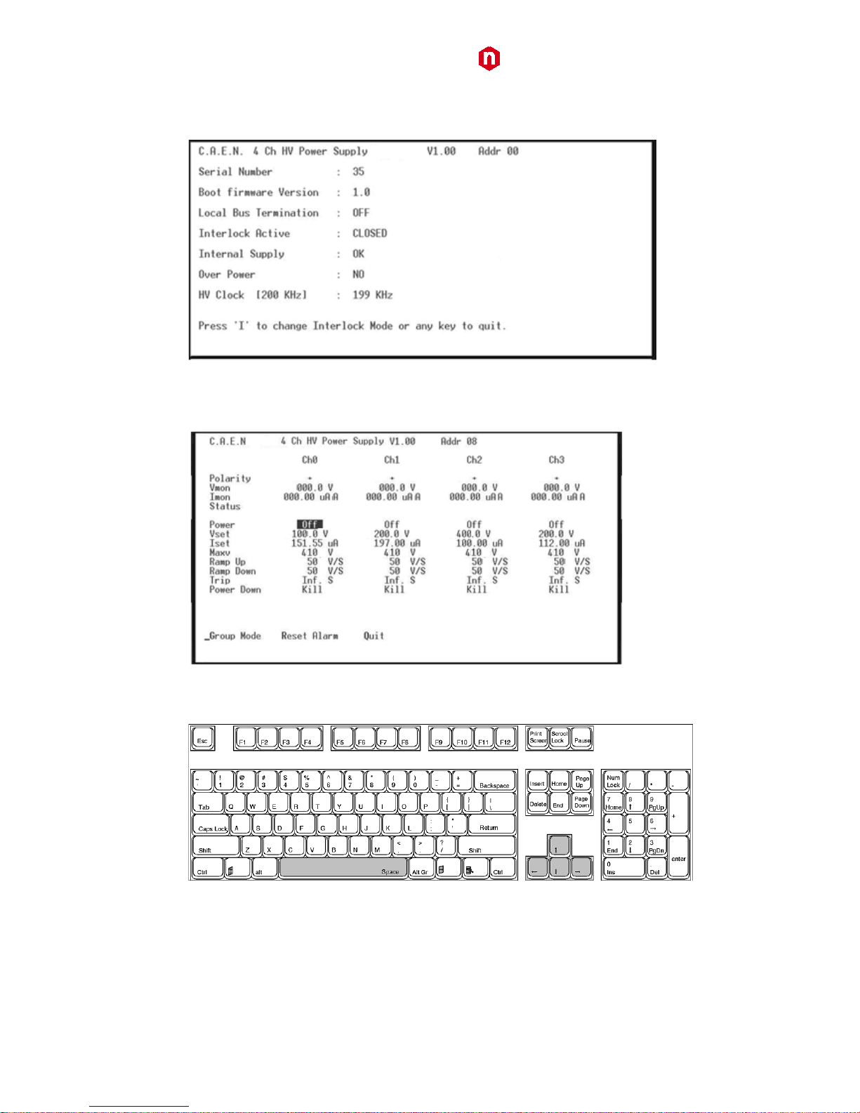
Remote Control: Main Menu
Fig. 45: Main Menu
Type D to set/monitor channels parameters
Type F to format the EEPROM
Type G to monitor board status
Type U to upgrade the firmware
Type O to perform the current offset calibration
Type Q to exit the program
Page 27
CAEN
Electronic Instrumentation
UM2619 – N1419 User Manual
27
Remote Control: General Menu
By typing G it is possible to access the General Menu which includes the board’s general settings.
Fig. 46: Board Status Menu
Remote Control: Channels Menu
By typing D it is possible to monitor and set all the channels parameters listed at p.15
Fig. 47: Channels Menu
In order to change one parameter: point the parameter with the arrow keys (see figure below), and type the
desired value, confirm by pressing <Enter>; Power and Power Down can be changed using the <Space> bar.
Fig. 48: PC keyboard
When one parameter is active, by typing G it is possible to make a “group setting”, i.e. broadcast the same value to
all channels (the parameter becomes active on all channels, see figure).
Page 28

CAEN
Electronic Instrumentation
UM2619 – N1419 User Manual
28
Fig. 49: Channels group setting
Type Q to exit the Menu.
Remote Control: firmware upgrade
By typing U it is possible to access the firmware upgrade menu:
Fig. 50: Firmware Upgrade Menu/1
If <y> is typed, then the following menu is shown:
Fig. 51: Firmware Upgrade Menu/2
At this point it is necessary to upload the updated firmware.
If "HyperTerminal" is used it is necessary to perform "Transfer" and "Send Text File" operations by selecting the file
"N1419.xxx"
Page 29
CAEN
Electronic Instrumentation
UM2619 – N1419 User Manual
29
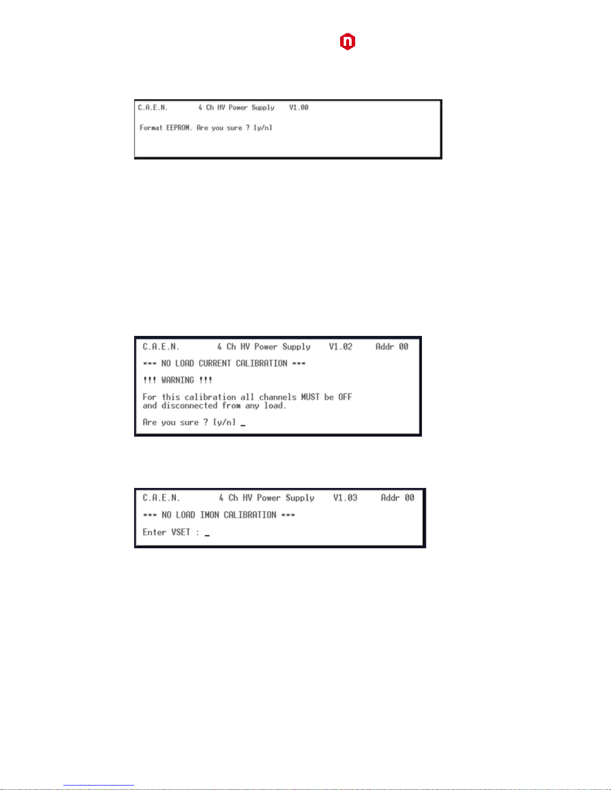
Remote Control: format EEPROM
By typing F it is possible to access the format EEPROM menu:
Fig. 52: Format EEPROM Menu
After the FORMAT command, all the channels have the following settings:
Vset = 0 V
Iset = 21.0 µA
Ramp Up / Down = 5 V/s
Trip = 10 s
MaxV = 510 V
Power Down = Kill
Module setting:
Interlock Mode = Active CLOSED
Remote Control: Current offset calibration
By typing O it is possible to perform the current offset calibration (the calibration must be performed after
30minutes operation at least); it is necessary to perform a calibration anytime external operating conditions
change; the following instructions are displayed:
Fig. 53: Current offset calibration warning
Once channels are off and disconnected from the load, type y; at this point the program asks for the current value
(VSET) selected for the offset compensation, such value is common to all channels; factory calibration is performed
at 250V, type VSET then press <ENTER>
Fig. 54: Current offset calibration VSET selection
Page 30

CAEN
Electronic Instrumentation
UM2619 – N1419 User Manual
30
the calibration is performed and the program asks for coefficients to be saved.
Fig. 55: Current offset calibration confirmation
USB - RS485 Communication Protocol
The following Protocol allows to communicate with up to 32 daisy chained modules. The Protocol is based on
commands made of ASCII characters strings. The protocol requires firmware revision 1.0.1 or greater.
Command Format
The Format of a command string is the following :
$BD:**,CMD:***,CH*,PAR:***,VAL:***.**<CR, LF >
The fields that form the command are :
BD : 0..31 module address (to send the command)
CMD : MON, SET
CH : 0..4 (4 for the commands related to all Channels)
PAR : (see parameters tables)
VAL : (numerical value must have a Format compatible with resolution and range)
Format of response string
Format response in case of error
String
Function (Units)
#BD:**,CMD:ERR
Wrong command Format or command not recognized
#BD:**,CH:ERR
Channel Field not present or wrong Channel value
#BD:**,PAR:ERR
Field parameter not present or parameter not recognized
#BD:**,VAL:ERR
Wrong set value (<Min or >Max)
#BD:**,LOC:ERR
Command SET with module in LOCAL mode
Each string is terminated by < CR, LF >
Format response in case of correct command
String
Function (Units)
#BD:**,CMD:OK
command Ok
#BD:**,CMD:OK,VAL:***
command Ok *** = value for command to individual Channel
#BD:**,CMD:OK,VAL:*;*;*;*
command Ok *;*;*;* = values Ch0,1,2,3 for command to all Channels
Numerical value Field 'VAL' has Format compatible (comma and decimal part) with the resolution and the range
related to the parameter.
Each string is terminated by < CR, LF >
MONITOR commands related to the Channels
The following table contains the strings to be used to handle monitor commands related to the Channels.
Page 31

CAEN
Electronic Instrumentation
UM2619 – N1419 User Manual
31
The 'X' in the Field 'Channel' can be set in the '0..4' range.
When 'X=4' the module returns the values of the parameter of all 4 Channels.
String
Function (Units)
$BD:xx,CMD:MON,CH:X,PAR:VSET
Read out VSET value ( XXXX.X V )
$BD:xx,CMD:MON,CH:X,PAR:VMIN
Read out VSET minimum value ( 0 V)
$BD:xx,CMD:MON,CH:X,PAR:VMAX
Read out VSET maximum value ( 500.0 V )
$BD:xx,CMD:MON,CH:X,PAR:VDEC
Read out VSET number of decimal digits
$BD:xx,CMD:MON,CH:X,PAR:VMON
Read out VMON value ( XXXX.X V )
$BD:xx,CMD:MON,CH:X,PAR:ISET
Read out ISET value ( XXXX.XX µA )
$BD:xx,CMD:MON,CH:X,PAR:IMIN
Read out ISET minimum value ( 0 µA )
$BD:xx,CMD:MON,CH:X,PAR:IMAX
Read out ISET maximum value ( 200.00 µA )
$BD:xx,CMD:MON,CH:X,PAR:ISDEC
Read out ISET number of decimal digits
$BD:xx,CMD:MON,CH:X,PAR:IMON
Read out IMON value ( XXXX.XX µA )
$BD:xx,CMD:MON,CH:X,PAR:IMRANGE
Read out IMON RANGE value ( HIGH / LOW )
$BD:xx,CMD:MON,CH:X,PAR:IMDEC
Read out IMON number of decimal digits (2 HR, 3 LR)
$BD:xx,CMD:MON,CH:X,PAR:MAXV
Read out MAXVSET value ( XXXX V )
$BD:xx,CMD:MON,CH:X,PAR:MVMIN
Read out MAXVSET minimum value ( 0 V )
$BD:xx,CMD:MON,CH:X,PAR:MVMAX
Read out MAXVSET maximum value ( 510 V )
$BD:xx,CMD:MON,CH:X,PAR:MVDEC
Read out MAXVSET number of decimal digits
$BD:xx,CMD:MON,CH:X,PAR:RUP
Read out RAMP UP value ( XXX V/S )
$BD:xx,CMD:MON,CH:X,PAR:RUPMIN
Read out RAMP UP minimum value ( 1 V/S )
$BD:xx,CMD:MON,CH:X,PAR:RUPMAX
Read out RAMP UP maximum value ( 50 V/S )
$BD:xx,CMD:MON,CH:X,PAR:RUPDEC
Read out RAMP UP number of decimal digits
$BD:xx,CMD:MON,CH:X,PAR:RDW
Read out RAMP DOWN value ( XXX V/S )
$BD:xx,CMD:MON,CH:X,PAR:RDWMIN
Read out RAMP DOWN minimum value ( 1 V/S )
$BD:xx,CMD:MON,CH:X,PAR:RDWMAX
Read out RAMP DOWN maximum value (50 V/S)
$BD:xx,CMD:MON,CH:X,PAR:RDWDEC
Read out RAMP DOWN number of decimal digits
$BD:xx,CMD:MON,CH:X,PAR:TRIP
Read out TRIP time value ( XXXX.X S )
$BD:xx,CMD:MON,CH:X,PAR:TRIPMIN
Read out TRIP time minimum value ( 0 S )
$BD:xx,CMD:MON,CH:X,PAR:TRIPMAX
Read out TRIP time maximum value ( 1000.0 S )
$BD:xx,CMD:MON,CH:X,PAR:TRIPDEC
Read out TRIP time number of decimal digits
$BD:xx,CMD:MON,CH:X,PAR:PDWN
Read out POWER DOWN value ( RAMP / KILL )
$BD:xx,CMD:MON,CH:X,PAR:POL
Read out POLARITY value ( '+' / '-' )
$BD:xx,CMD:MON,CH:X,PAR:STAT
Read out Channel status value ( XXXXX )
Meaning of STATUS bits (value read in decimal Format)
Bit
Function
Bit 0 → ON
1 : ON 0 : OFF
Bit 1 → RUP
1 : Channel Ramp UP
Page 32
CAEN
Electronic Instrumentation
UM2619 – N1419 User Manual
32
Bit 2 → RDW
1 : Channel Ramp DOWN
Bit 3 → OVC
1 : IMON >= ISET
Bit 4 → OVV
1 : VMON > VSET + 2.5 V
Bit 5 → UNV
1 : VMON < VSET – 2.5 V
Bit 6 → MAXV
1 : VOUT in MAXV protection
Bit 7 → TRIP
1 : Ch OFF via TRIP (Imon >= Iset during TRIP)
Bit 8 → OVP
1 : Power Max; Power Out > 0.11W
Bit 9 → OVT
1: TEMP > 105°C
Bit 10 → DIS
1 : Ch disabled (REMOTE Mode and Switch on OFF position)
Bit 11 → KILL
1 : Ch in KILL via front panel
Bit 12 → ILK
1 : Ch in INTERLOCK via front panel
Bit 13 → NOCAL
1 : Calibration Error
Bit 14, 15 → N.C.
MONITOR commands related to the module
The following table shows the strings to be used to handle monitor commands related to the module.
String
Function (Units)
$BD:xx,CMD:MON,PAR:BDNAME
Read out module name ( N1419 )
$BD:xx,CMD:MON,PAR:BDNCH
Read out number of Channels present ( 1, 2, 4 )
$BD:xx,CMD:MON,PAR:BDFREL
Read out Firmware Release ( XX.X )
$BD:xx,CMD:MON,PAR:BDSNUM
Read out value serial number ( XXXXX )
$BD:xx,CMD:MON,PAR:BDILK
Read out INTERLOCK status ( YES/NO )
$BD:xx,CMD:MON,PAR:BDILKM
Read out INTERLOCK mode ( OPEN/CLOSED )
$BD:xx,CMD:MON,PAR:BDCTR
Read out Control Mode (LOCAL / REMOTE )
$BD:xx,CMD:MON,PAR:BDTERM
Read out LOCAL BUS Termination status ( ON/OFF )
$BD:xx,CMD:MON,PAR:BDALARM
Read out Board Alarm status value ( XXXXX )
Page 33

CAEN
Electronic Instrumentation
UM2619 – N1419 User Manual
33
Meaning of Board Alarm bits
Bit
Function
Bit 0 → CH0
1 : Ch0 in Alarm status
Bit 1 → CH1
1 : Ch1 in Alarm status
Bit 2 → CH2
1 : Ch2 in Alarm status
Bit 3 → CH3
1 : Ch3 in Alarm status
Bit 4 → PWFAIL
1 : Board in POWER FAIL
Bit 5 → OVP
1 : Board in OVER POWER
Bit 6 → HVCKFAIL
1 : Internal HV Clock FAIL (≠ 200±10kHz)
SET commands related to the Channels
The following table contains the strings to be used to handle set commands related to the Channels.
The 'X' in the Field 'Channel' can be set to the '0..(N-1)' values.
7
When 'X=N' the command is issued to all Channels.
String
Function (Units)
$BD:xx,CMD:SET,CH:X,PAR:VSET,VAL:XXXX.X
Set VSET value
$BD:xx,CMD:SET,CH:X,PAR:ISET,VAL:XXXX.XX
Set ISET value
$BD:xx,CMD:SET,CH:X,PAR:MAXV,VAL:XXXX
Set MAXVSET value
$BD:xx,CMD:SET,CH:X,PAR:RUP,VAL:XXX
Set RAMP UP value
$BD:xx,CMD:SET,CH:X,PAR:RDW,VAL:XXX
Set RAMP DOWN value
$BD:xx,CMD:SET,CH:X,PAR:TRIP,VAL:XXXX.X
Set TRIP time value
$BD:xx,CMD:SET,CH:X,PAR:PDWN,VAL:RAMP/KILL
Set POWER DOWN mode value
$BD:xx,CMD:SET,CH:X,PAR:IMRANGE,VAL:HIGH/LOW
Set IMON RANGE value
8
$BD:xx,CMD:SET,CH:X,PAR:ON
Set Ch ON
$BD:xx,CMD:SET,CH:X,PAR:OFF
Set Ch OFF
SET commands related to the module
String
Function (Units)
$BD:xx,CMD:SET,PAR:BDILKM,VAL:OPEN/CLOSED
Set Interlock Mode
$BD:xx,CMD:SET,PAR:BDCLR
Clear alarm signal
7
N is the number of channels
8
parameter 'IMRANGE' can be changed only on modules featuring IMON zoom (optional)
Page 34
CAEN
Electronic Instrumentation
UM2619 – N1419 User Manual
34
4. Internal Settings
Polarity selection
The output polarity is independently selectable for each channel. Note that the polarity is indicated by two LEDs for
each channel on the front panel.
In order to change the polarity:
• Wear Antistatic Gloves
• Switch off the unit
• Wait for the complete discharge of the capacitors.
• Lay down the unit, right side up
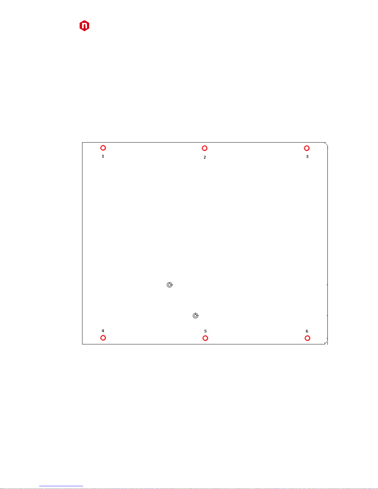
• Remove screws 1, 2, 3, 4, 5, 6, see figure (red):
Fig. 56: Side cover removal instructions
• Lift the side cover gently
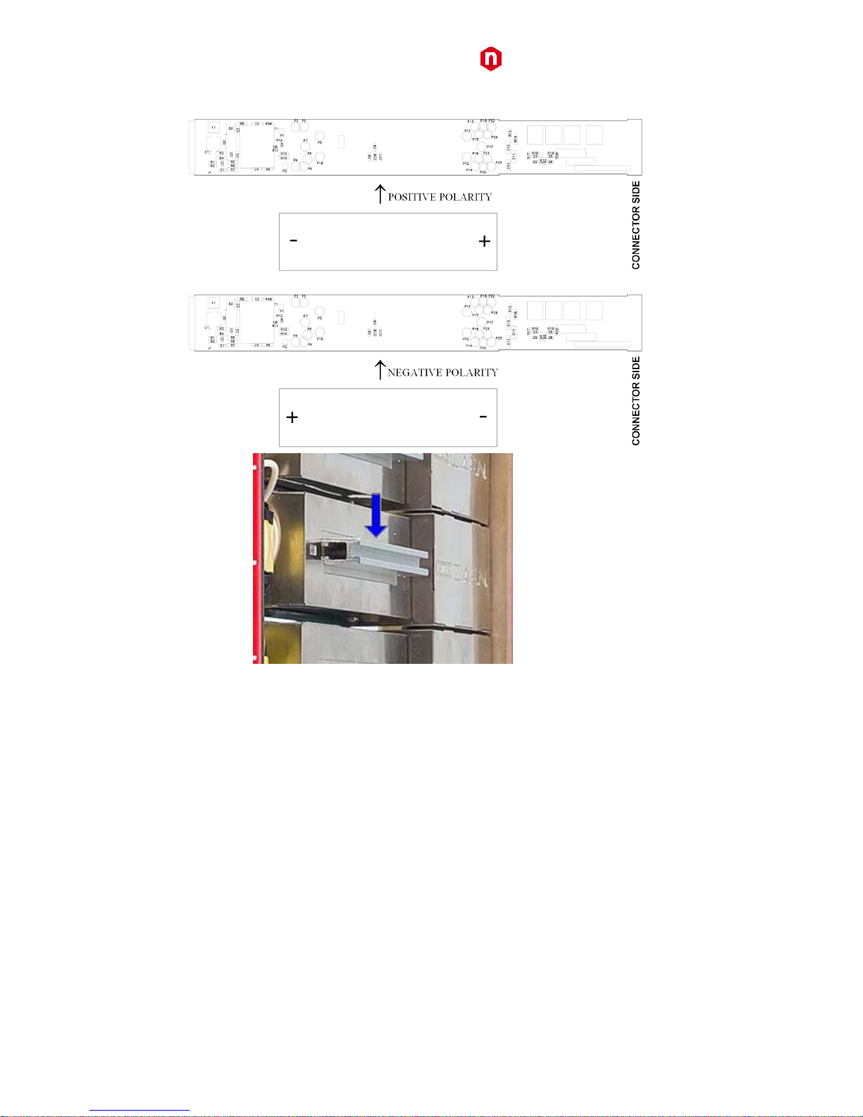
• At this point it is possible to change the channel polarity: refer to the following figure (the blue arrow
indicates diode bridge box placed to configure channel as POSITIVE).
• During this operation pay attention not to bend the pins, as they are plugged completely in their sockets
Page 35
CAEN
Electronic Instrumentation
UM2619 – N1419 User Manual
35
Fig. 57: Polarity selection instructions
• In order to choose the POSITIVE POLARITY, plug the diode bridge box, with the + symbol towards the
connector side.
• In order to choose the NEGATIVE POLARITY, plug the diode bridge box, with the - symbol towards the
connector side.
• Always pull and plug the diode bridge box by holding it on the handle pointed by the arrow in Fig. above.
Once settings are done, put the right side cover back in place with screws 1, 2, 3, 4, 5, 6.
Page 36

CAEN
Electronic Instrumentation
UM2619 – N1419 User Manual
36
Internal switches
Fig. 58: Dip switch position
Local Bus termination
The SW[1..3] switch placed on the Microcontroller board inside the module (behind the Remote communication
control section, see p. 12), allows to terminate the Local Bus for daisy chain purposes (see p. 24); dot NOT visible =
Termination ON.
RS485 – RS232 conversion
The SW[200, 201] switch placed on the Microcontroller board inside the module, allows to adapt RS485 signals to
RS232; dot visible = Adaptation ON.
Page 37
CAEN
Tools for Discovery
Electronic Instrumentation
UM2619 – N1419 User Manual
37
CAEN SpA is acknowledged as the on ly company i n the world providing a complete range of High/Lo w Voltage Po wer
Supply systems and Fro nt-End/Data Acquisition modules which meet I EEE Standards for Nuclear and Particle Physics.
Extensive Research and Development capabilities have allowed CAEN SpA to play an important, long term role in this field.
Our activities have always been at the forefront of technology, thanks to years of intensive collabora tions with the most
important Research Cen tres of the world. Our produc
ts appeal to a wide range of customers including engineers, scientists
and technical professionals who all trust them to help achieve their goals faster and more effectively.
CAEN S.p.A. CAEN GmbH CAEN Technologies, Inc.
Via Vetraia, 11 Eckehardweg 10 1140 Bay Street - Suite 2 C
55049 Viareggio
42653 Solingen
Staten Island, NY 10305
Italy
Germany
USA
Tel. +39.0584.388.398
Tel. +49.212.2544077
Tel. +1.718.981.0401
Fax +39.0584.388.959
Mobile +49(0)15116548484
Fax +1.718.556.9185
Fax +49.212.2544079
www.caen.it
www.caentechnologies.com
www.caen-de.com
CAEN
Tools for Discovery
Electronic Instrumentation
Guide GD2619 - N1419 User Manual rev. 1 - 30 November 2012
00106-11-N1419-MUTX
Copyright © CAEN SpA. All rights reserved. Information in this publication supersedes all earlier versions. Specifications subject to change without notice.
 Loading...