

Page 1
Dual valve design (Separate tube head amp and tube output circuits)
Dual custom wound humbucking output transformers
Large capsule with 1.25 diameter, 3 micron thick gold sputtered
diaphragms (Exclusive CAD Optema Series)
Multi-pattern (Cardioid, Figure 8, and Omnidirectional)
Heavy duty analog power supply
Digital 24 bit output option with 120 dB dynamic range and sampling
rates up to 96KHz.
Detachable capsule/screen assembly for optional capsules with
alternate frequency responses.
8 and 16 dB non-capacitive pad
80 Hz high pass filter.
Includes ZM-2 shock mount
Professional Microphones
Page 2
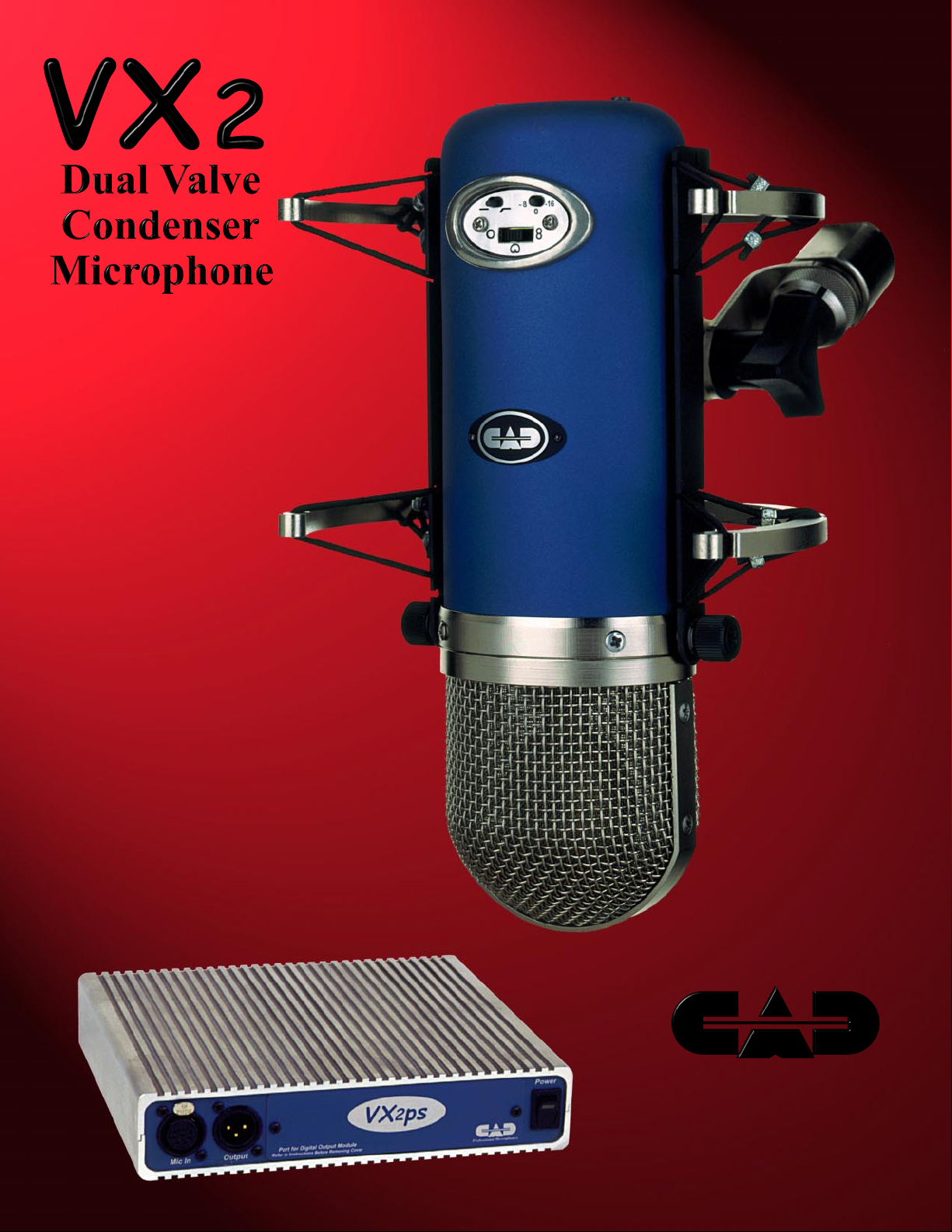
Dual Valve Condenser Microphone
Introducing the VX2... a new dawn
at CAD. The VX2 features a totally
new approach to tube microphone design. Each side of the extra large
Optema condenser capsule has its
own independent tube head amp and
output amplifier, including separate
high quality custom output transformers. The dual tube design allows
the head amp tube to be optimized
for low noise, while the output tube
is optimized for driving the transformers and cables. Polar pattern
switching is done at the output of the
microphone rather than at the capsule.
This computer optimized design results in a noise floor that is lower then
many FET mics, but still has considerable headroom. This is all done
without having to resort to a solid
state output section that could detract
from the true tube sound. The tube
circuit has been optimized for flat
phase response and has a bandwidth
that extends beyond 100KHz. This results in audibly superior transparency.
The Optema capsule in the VX2 is
produced in our capsule facility in
Conneaut, Ohio. This new capsule is
extremely large with an actual diaphragm diameter of 1 1/4". The high
tension diaphragms are aged, gold
sputtered, and made from the newest 3 micron thick high strength polymer film. The other capsule components are precision machined brass
and stainless steel. Each capsule is
hand dampened and assembled in a
state of the art clean room facility.
The screen/capsule assembly is easily removable in the field for use with
optional capsules that will be available to further increase the versatility of the VX2 for various recording
applications.
The included power supply for the
VX2 is an analog design utilizing a
toroidal power transformer. Available soon as an option, is a 24-bit digital output module for the VX2 with
32 to 96 kHz sampling rates and 120
dB dynamic range.
Use and Operation
Mount the microphone in the desired location.
Plug the included seven pin cable into the microphone and the power supply. The output of the
microphone is at the 3 pin XLR connector on the
power supply. Use a standard balanced 3 pin XLR
cable to connect the microphone output to the input of your mixer or recorder. Phantom power is
not required. Plug the power supply into your AC
mains supply. Turn the power supply on using the
rocker switch on the right side of the front panel
of the power supply. The LED on the rocker switch
should light. Allow several minutes for the vacuum
tubes in the microphone to warm-up and stabilize. The output level of the VX2 is quite high. It
is recommended that you start with trim control
or input level control turned down on your mixer
or recorder. It is also recommended that you turn
down your input level whenever changing any of
the switch settings on the microphone.
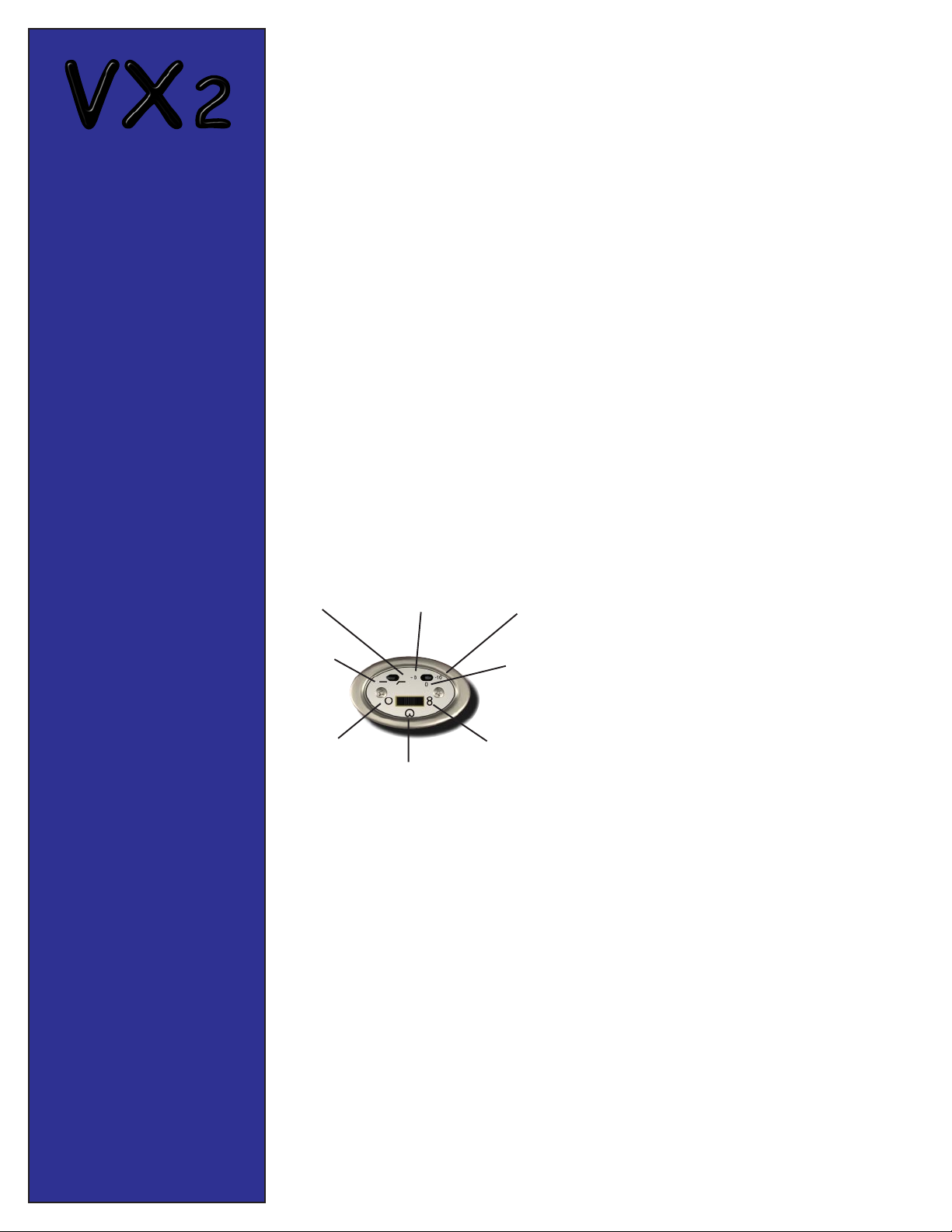
VX2 Switch Functions
High-Pass
On
Flat
Response
Omnidirectional
-8 dB Pad
Engaged
Cardioid
-16 dB Pad
Engaged
Pad Off
(0 dB)
Figure 8
ZM-2 Shock Mount
The ZM-2 shock mount is an integral part of the
VX2 microphone and only needs to be removed
to service the microphone or to exchange the capsule/screen assembly with a different type. To
remove the shock mount, unscrew the two
knurled knobs on either side of the microphone
head first, then unscrew the knurled knob in the
back of the microphone.
To replace the shock mount, install the knurled
knob in the back of the microphone FIRST. Then
install the knurled knobs on the sides of the microphone head.
Power Supply
The VX2PS power supply is set for 117VAC operation at the factory. For 220VAC operation,
change the switch on the rear panel of the supply
to 220V.
Care and Maintenance
The VX2 should be kept in clean dry environment, free from temperature extremes. If the housing becomes soiled, it can be cleaned
with a cloth moistened in isopropyl alcohol.
Removing the Capsule/Screen Assembly
The capsule/screen assembly can be easily removed for use with
optional VX2 condenser capsules. First disconnect the microphone
from the power supply and remove it from the shock mount. (See
above section on ZM-2.) Place the microphone on a soft flat surface to avoid damage to the screen/capsule assembly. Remove the
three screws at the base of the screen assembly. The complete head
will now simply lift off. Use care to avoid damage to the small gold
spring contacts. Place the alternate head on top of the body with the
three gold spring contacts towards the back of the microphone. Replace the three screws and secure the microphone in the shock mount.
Contact CAD Sales for price and availability of optional capsule/
screen assemblies.
This Microphone Demands Respect!!*
* For the potentially lethal voltages inside the microphone and power
supply during operation. Never open the microphone housing when
it is connected to the power supply. The power supply has no user
serviceable parts inside. The power supply should only be opened
by a qualified service technician.
Tube Replacement
The tubes that are used in the VX2 have been hand selected for low
noise, and burned in to provide years of service. The VX2 uses 2
different tubes. A 12AX7 (V1) is used for the head-amp and a 12AU7
(V2) for the output section. The actual number that appears on the
tubes in your microphone may be different. These tubes are a very
popular type that are used in many guitar amplifiers and music equipment. However, to insure continued operation within factory specs,
it is recommended that you purchase replacement tubes from CAD.
Contact the CAD sales department.
To gain access to the tubes, first disconnect the microphone from
its power supply. Remove the microphone from the shock mount
by unscrewing the two knurled knobs on either side of the microphone head. Then unscrew the single knurled knob on the back of
the mic near the XLR connector.
To make it easier to remove the housing, place the small toggle
switches in the high-pass, and -8 dB pad position. Remove the switch
bezel by removing the screws on the sides of the bezel. Remove the
mic housing by unscrewing the two screws on the end of the mic
near the XLR connector. Carefully slide the housing off, making
sure the housing clears the small toggle switches.
The tube positions are marked on the printed circuit board near
each tube socket. The 12AX7 is V1, the 12AU7 is V2. Make sure
that the tubes are seated firmly in each socket.
Replace the body by sliding it over the chassis, being careful to
clear the small toggle switches. Center the body over the XLR connector at the end of the chassis. The XLR connector should the hole
at the end of the body part way. Replace the screws in the end of the
housing. Replace the switch bezel and the switch bezel screws. Note:
If the screws in the switch bezel do not align properly, the body may
not be fully seated. Loosen the screws on the body and realign it
first.
Page 3

Optema Series, OS-125 Dual
Diaphragm Condenser Capsule
The OS-125 condenser capsule is the standard capsule supplied with the VX2 microphone. OS-125 capsules are
produced in a state-of-the-art cleanroom at our condenser capsule production facility in Conneaut, Ohio. The
OS-125 capsule has the following features:
True large diameter capsule with 1-1/4" inside diameter. (1-1/2" outside diameter.)
3 Micron thick high tension, diaphragms made form the latest high strength polymer film.
OS-125 Capsule shown approxi-
mately life size.
VX2 Frequency Response Characteristics with Standard OS-125 Capsule
24K Gold sputtered diaphragm coating.
Each capsule is hand adjusted for proper damping and consistent frequency response.
Other capsule components made from precision machined brass and stainless steel.
Cardioid
Figure 8
Omnidirectional
Professional Microphones
CAD 341 Harbor St. Conneaut, OH 44030 (440) 593-1111 Fax (440) 593-5395
Page 4

Optional Digital Output Module
The optional digital output module installs in the front of the VX2 power supply. Preliminary specifications for this module appear on the following page. See
the installation instructions included with the module before removing the over panel on the front of the power supply. Contact CAD sales for price and
availability of the digital output module.
VX2 Specifications:
Type:
Side address, multi-pattern true condenser. Dual tube electronics.
Frequency Response:
10-20 kHz.
Polar Patterns:
Cardioid, Figure eight, Omnidirectional .
Impedance:
Low (200 ohms nominal).
Output Level At 1 kHz.:
Open Circuit Voltage:
-55 dB (0 dB = 1 volt per microbar).
17.8 mV/Pascal.
Dynamic Range:
116 dB (Noise floor to max SPL @ less than 0.5% THD).
123 dB (Noise floor to max SPL @ less than 5.0% THD).
Equivalent Noise Level:
13 dB Equivalent SPL, A weighted, cardioid.
Maximum Output Level:
+10.0 dBV (@ 136 dB SPL, less than 5.0% THD).
Maximum SPL:
145 dB SPL (With 16 dB pad, less than 0.5% THD ).
152 dB SPL (With 16 dB pad, less than 5.0% THD ).
Total Harmonic Distortion:
Less than 0.5% @ 129dB SPL without pad.
Less than 5.0% @ 136 dB SPL without pad.
Signal-To-Noise Ratio:
81 dB (At 94 dB SPL).
Capsule Capacitance:
60 pF.
Powering:
Included VX2 analog power supply.
Connector:
7 pin XLR, microphone.
3 pin XLR, audio out from power supply.
Cable:
Professional quality 7 conductor, 30 ft. long.
Finish:
Matte blue housing, nickel plated screen assembly.
Dimensions (Microphone):
2.42" x 2.87" x 9.2" long.
Dimensions (VX2PS Power Supply):
8.370 (212.60mm)W x 1.715 (43.56mm)H x 7.250 (184.15mm)L.
Net Weight (Microphone):
30 oz. (850 grams).
Net Weight (VX2PS Power Supply):
3lb, 9 oz. (1615 grams).
Optional Digital Interface
Preliminary Specifications:
NOTE: Specifications for the Digital Interface may change to conform to standards
established by the A.E.S.S.C. committee on digital microphones.
The optional digital interface mounts in the VX2 power supply and can be field
installed. Features include:
24 Bit resolution.
Adjustable sample rates of 96kHz, 48kHz, 44.1kHz and 32kHz.
120 dB dynamic range (A weighted).
Low noise and distortion (>105 dB THD + noise).
Differential analog architecture.
Linear phase digital anti-alias filtering.
Unique psychoacoustic noise shaping filter which subjectively truncates
the output to 16, 18, or 20 bits while 24 bit sound quality is preserved.
LED VU meter.
Fully transformer isolated.
AES/EUB or S/PDIF format.
XLR and RCA output connectors.
Included Accessories:
ZM-2 ....... External shock mount.
30 ft. professional quality 7 conductor cable with gold plated XLR male and female
connectors.
Rugged carrying case.
Optional Accessories:
VX2 digital output module.
TWO-YEAR LIMITED WARRANTY
CTI Audio, Inc. (CAD) hereby warrants that this product will be free of defects in
material and workmanship for a period of two years from the date of purchase. In the
unlikely event a defect occurs CAD will, at its option, either repair or replace with a
new unit of equal or greater value. You should retain proof of purchase to validate the
purchase date and return it with any warranty claim. Return warranty claims carefully
packed, insured and prepaid to the Service Department at the address listed below.
This warranty excludes exterior finish or appearance, damage from abuse, misuse of
the product, use contrary to CADs instructions or unauthorized repair. All implied
warranties or merchantability or fitness for a particular purpose are hereby disclaimed
and CAD hereby disclaims liability for incidental, special or consequential damages
resulting from the use or unavailability of this product.
This warranty gives you specific legal rights and you may also have other rights which
vary from state to state. Some states do not allow the exclusion or limitation of incidental or consequential damages or limitations on how long an implied warranty lasts, so
the above exclusions and limitations may not apply to you.
Note: No other warranty, written or oral is authorized by CTI Audio, Inc.
Professional Microphones
CAD 341 Harbor St. Conneaut, OH 44030 (440) 593-1111 Fax (440) 593-5395
 Loading...