

Page 1
2000 Cadillac DeVille
Outer Center Pillar Sectioning 1-4
Outer Front Pillar Sectioning 1-2
Quarter Panel Sectioning 1-6
Body Dimensions 1-17/18
Inner Center Pillar Sectioning 1-10
Inner Front Pillar Sectioning 1-9
Outer Wheelhouse Sectioning 1-12
Rear Rail Sectioning 1-13
Page 2

Outer Front Pillar, Center Pillar
and Quarter Panel Sectioning
CAUTION: When performing service on or near the Supplemental
Inflatable Restraint (SIR) components or the SIR wiring, the SIR system
must be disabled. Failure to follow the correct procedure could cause air
bag deployment, personal injury or unnecessary SIR system repairs.
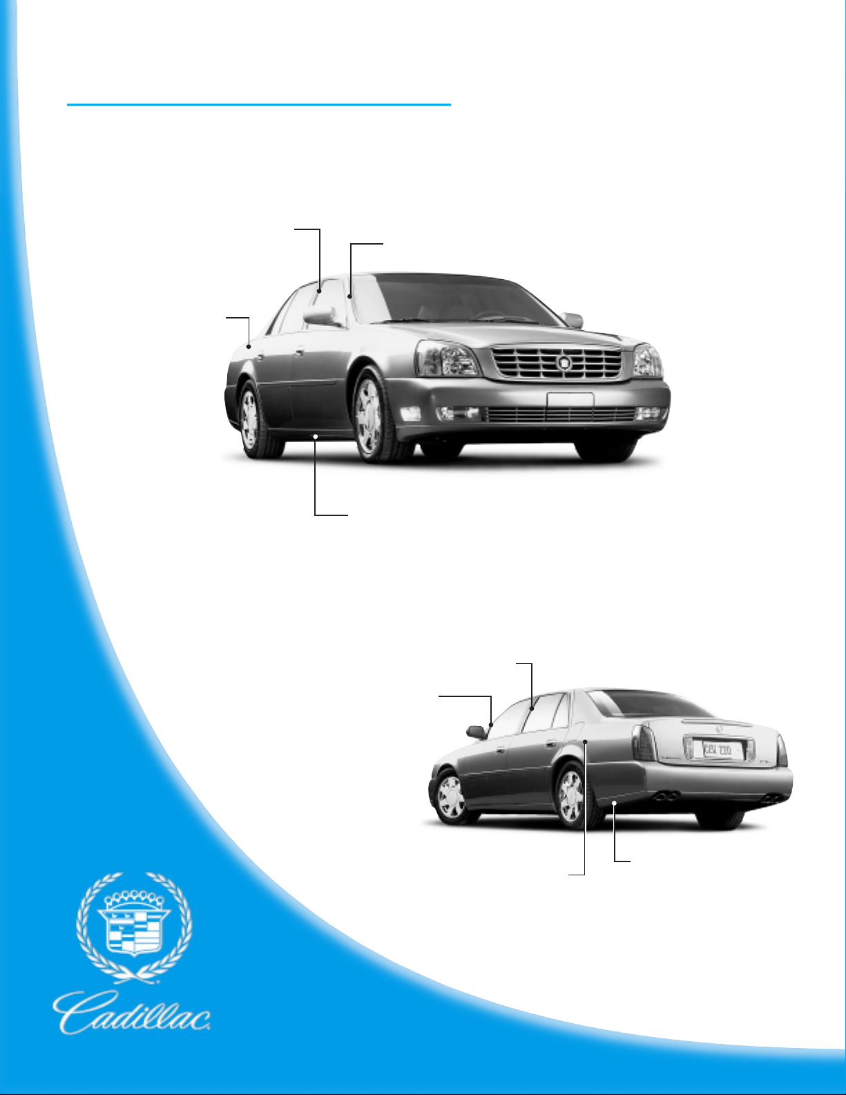
The full body side outer panel comes as a one-piece assembly and can be
replaced at factory seams after removal of glass and roof. Any one of these
procedures can be performed separately, or in any combination, dependent
upon the extent of damage to the vehicle. Sectioning must take place in
specified areas only (Fig. 1-1). Remove front glass when sectioning front pillar
and rear glass for rear pillar repair.
IMPORTANT: When replacing panels that involve servicing stationary
glass, refer to GM Service Bulletin 43-10-48 before performing any
priming or refinishing.
Fig.␣ 1-1 — 2000 DeVille Outer Frame Sectioning Locations
2000 cadillac deville 1-1
Page 3

Outer Front Pillar
Sectioning
Removal Procedure
IMPORTANT: Sectioning should be performed
only in the recommended areas. Failure to do
so may compromise the structural integrity of
the vehicle.
1. Visually inspect and restore as much of the
damage as possible to factory specifications.
2. Remove the following:
• Fender
• Windshield
• Door
• Hinge pillar blocks
3. Determine sectioning locations. Section in
approved areas only (see Fig.␣ 1-1).
4. Mark locations and cut part through outer
panel only.
5. Locate factory welds and drill out, noting
number and locations of welds (Fig.␣ 1-2).
6. Locate and drill out spot welds on weather
strip retainer as necessary. It is not necessary
to remove complete retainer.
7. Remove outer panel.
8. Note placement and number of foam baffles
for new installation. If baffles are damaged,
replacement service parts are available.
IMPORTANT: Hinge pillar blocks must be
replaced if damaged.
9. Clean adhesive and sealer from hydroformed
reinforcement tube as necessary. Note
location for reinstallation.
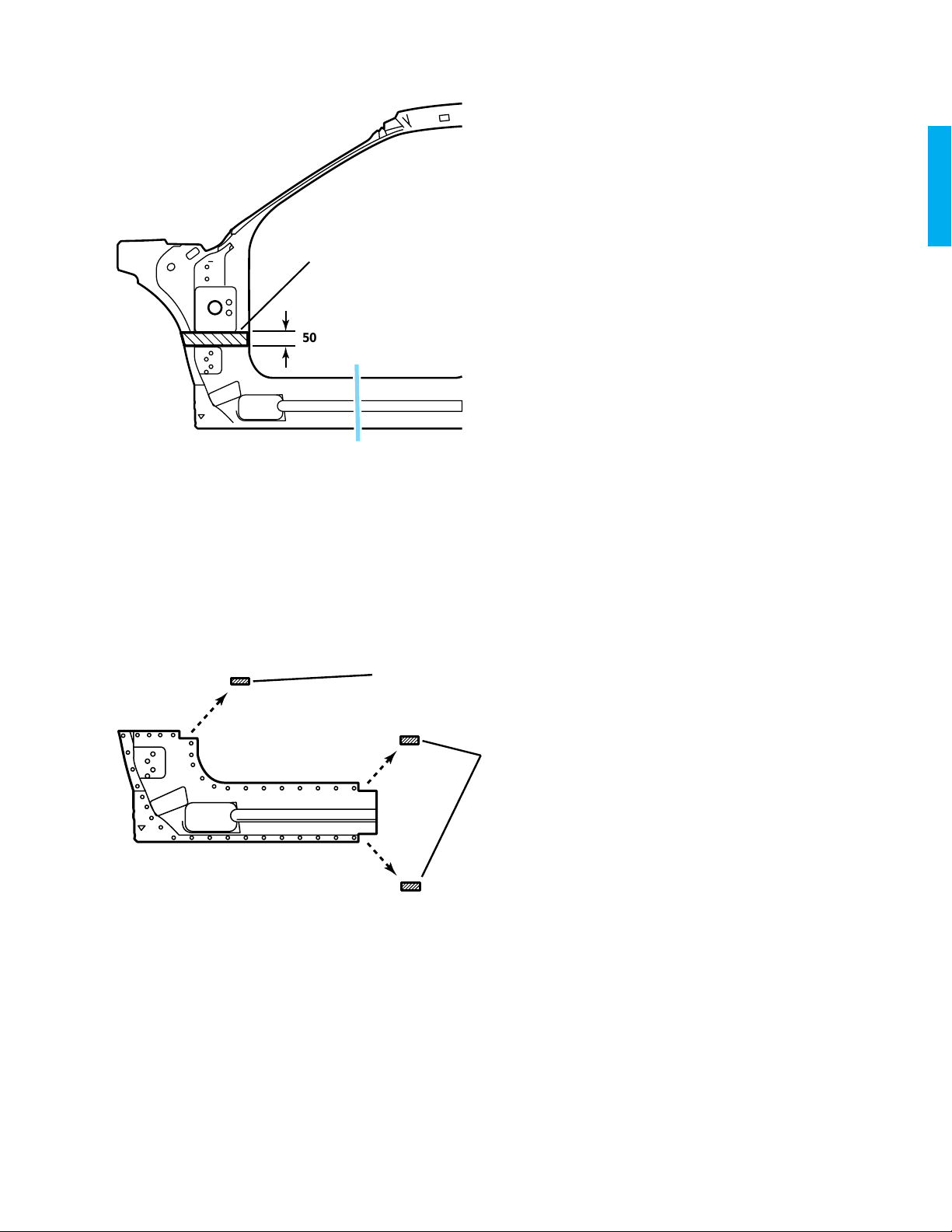
Fig.␣ 1-2 — Drill Out Welds
100 MM (4 IN)
Service Part Preparation
1. Cut service part in corresponding locations to
fit original cut lines. Leave a gap of one-andone half times the metal thickness of
sectioning joint.
2. Create 100␣ mm (4␣ in) backing plate on rocker
panel from unused portion of service part
(Fig.␣ 1-3).
3. In windshield pillar area, use the hydroformed
inner rail for backing plate.
4. Drill 8␣ mm (5/16␣ in) plug weld holes in service
part according to original locations as noted.
Drill plug weld holes spaced 40␣ mm (1-5/8␣ in)
apart along backing plate location 25␣ mm
(1␣ in) from joint edge.
1-2 2000 cadillac deville
GAP = ONE-AND-ONE-HALF TIMES
THE METAL THICKNESS
Fig.␣ 1-3 — Rocker Panel Backing Plate
Page 4

Fig.␣ 1-4 — Plug Weld and Stitch Weld
Installation Procedure
IMPORTANT: Remove all foam prior to welding
this section of the service panel.
1. Prepare mating surfaces.
2. Apply weld-through primer to mating surfaces
prior to assembly.
3. Weld backing plates to vehicle at rocker.
IMPORTANT: Replace hinge pillar blocks
prior to welding outer panel.
4. Apply windshield bonding adhesive to the
hydroformed reinforcement as noted from
removal procedure.
5. Position service part on vehicle. Clamp in
place. Check for proper fit.
6. Plug weld accordingly (Fig. 1-4).
7. Stitch weld along both sectioning joints. Make
25␣ mm (1␣ in) welds along the seam with
25␣ mm (1␣ in) gaps between, then go back and
complete the stitch weld to ensure structural
integrity of the vehicle.
8. Install insulating foam as necessary in areas
noted from original baffle locations.
IMPORTANT: Prior to refinishing, refer to
the publication GM4901M-D-2000 “GM
Approved Refinish Materials” for
recommended products. Do not combine
paint systems. Refer to paint manufacturer’s
recommendations.
9. Refinish as necessary.
2000 cadillac deville 1-3
Page 5

Outer Center Pillar
50 MM (2 IN)
GAP =
ONE-AND-ONE-HALF
TIMES THE MET AL
THICKNESS
Sectioning
Removal Procedure
IMPORTANT: Sectioning should be performed
only in the recommended areas. Failure to do so
may compromise the structural integrity of the
vehicle.
1. Locate an approved sectioning area in the
center pillar (Fig.␣ 1-5).
2. Mark and scribe a line. This is the cut location.
3. Cut Center Pillar at cut line. Use caution not to
cut inner reinforcement.
4. Create cut lines on rocker within approved
sectioning locations. Cut the rocker vertically
along cut lines.
5. Drill out factory welds. Note number and
location of welds.
6. Remove the damaged part.
7. Note placement and number of foam baffles
for new installation. If baffles are damaged,
replacement service parts are available.
IMPORTANT: Hinge pillar blocks must be
replaced if damaged.
Fig.␣ 1-5 — Outer Center Pillar – Sectioning
Locations
Preparation Of Service Part
1. On the service part, at center pillar mark a
horizontal line in corresponding locations
to original sectioning cut. Leave a gap of oneand-one-half times the thickness of the metal
at the sectioning joint (Fig. 1-6).
2. Mark vertical cut lines in rocker areas to
correspond with original section lines. Leave a
gap of one-and-one-half times the metal
thickness (see Fig. 1-3).
3. Cut the outer doorframe opening service part
along these three section lines.
4. Cut two 100␣ mm (4␣ in) pieces from the unused
portion of the service part for backing plates
in rocker.
5. Cut one 50␣ mm (2␣ in) backing plate for pillar
(Fig. 1-6). Remove the flange on each side of
the backing plates so that they will fit behind
the sectioning joint.
6. Drill 8␣ mm (5/16␣ in) plug weld holes in service
part according to original locations, as noted.
Drill plug weld holes spaced 40␣ mm (1-5/8␣ in)
apart along backing plate locations. Space
these holes 25␣ mm (1␣ in) from the joint edge
on the rocker panels and 13␣ mm (1/2␣ in) from
the joint edge on the pillar.
Fig.␣ 1-6 — Create Pillar Backing Plate
1-4 2000 cadillac deville
Page 6

Fig.␣ 1-7 — Outer Center Pillar – Installation
Installation Procedure
1. Install sleeves on vehicle at rocker and center
pillar areas using plug welds.
2. Replace hinge blocks and bolts.
3. Prepare mating surfaces.
IMPORTANT: Prior to refinishing, refer to the
publication GM4901M-D-2000 “GM
Approved Refinish Materials” for
recommended products. Do not combine
paint systems. Refer to paint manufacturer’s
recommendations.
4. Apply weld-through primer to mating
surfaces prior to assembly.
5. Align part and clamp in place. Check fit
(Fig. 1-7).
6. Spot blast plug weld areas.
7. Plug weld as necessary in original spot weld
locations and at backing plates.
8. Stitch weld at section joints, one inch on and
one inch off, as necessary, then go back and
complete the stitch weld. This will create a
solid joint with minimal heat distortion.
9. Dress welds and finish seams as necessary.
10. Refinish as necessary.
2000 cadillac deville 1-5
Page 7

Quarter Panel Sectioning
Removal Procedure
The service part comes with lower quarter panel
extension and taillamp pocket attached. These
parts can be left on the vehicle if not damaged.
Drill out factory welds on the car and service part
and use the outer panel only.
IMPORTANT: When replacing panels that
involve servicing stationary glass, refer to GM
Service Bulletin 43-10-48 before performing any
priming or refinishing.
IMPORTANT: Sectioning should be performed
only in the recommended areas (Fig. 1-8).
Failure to do so may compromise the structural
integrity of the vehicle.
IMPORTANT: It may be necessary to unplug
and remove one end of the body wiring harness
that runs through quarter pillar lower extension
if it is necessary to replace extension.
1. Visually inspect and restore as much of the
damage as possible to the factory
specifications.
2. Remove all related panels and components.
3. Remove all sealers, sound deadeners and anticorrosion materials as necessary.
4. Determine sectioning locations in rocker area
(Fig. 1-8).
5. Mark a line and cut in approved sectioning
areas of rocker.
6. In upper quarter panel door opening, locate
the fourth weatherstrip hole (1).
7. Measure down 25␣ mm (1␣ in) and mark a line.
8. In back-glass opening, locate rear edge of roof
panel.
9. Measure down 25␣ mm (1␣ in), and scribe a
second line. Connect marks at both locations
to create a cut line.
10. Cut part at marked locations.
11. Locate, mark and drill out all factory welds.
Note the number and location of welds for
installation of the service assembly.
12. Remove damaged panel. Note placement and
number of foam baffles for new installation. If
baffles are damaged, replacement service parts
are available.
1
25 MM (1 IN)
Fig.␣ 1-8 — Outer Rear Pillar Sectioning
1-6 2000 cadillac deville
Page 8

Fig.␣ 1-9 — Outer Rear Pillar Preparation
Fig.␣ 1-10 — Outer Rear Pillar Installation
Preparation Of Service Part
1. Cut service part in corresponding locations to
fit original cut lines. Leave a gap of one-andone-half times the metal thickness of
sectioning joint (Fig. 1-9).
2. Create 100␣ mm (4␣ in) backing plate on rocker
panel from unused portion of service part.
3. Create a 50␣ mm (2␣ in) backing plate on
quarter panel from unused portion of old
quarter panel.
4. Drill 8␣ mm (5/16␣ in) plug weld holes as noted
from original locations. At backing plates,drill
8␣ mm plug weld holes 13␣ mm (1/2␣ in) from
seam spaced 40␣ mm (1 1/2␣ in) apart.
Installation Procedure
1. Position service part on vehicle. Check fit
using body dimensions.
2. Temporarily remove service part.
3. Prepare mating surfaces.
IMPORTANT: Prior to refinishing, refer to
the publication GM4901M-D-2000 “GM
Approved Refinish Materials” for
recommended products. Do not combine
paint systems. Refer to paint manufacturer’s
recommendations.
4. Apply weld through primer to mating
surfaces.
5. Install GM P/N 12399117 Sealing Strip
between outer wheelhouse and gas door
pocket.
6. Weld backing plates into position on body.
7. Position service part and clamp in place. Spot
blast plug weld areas. Plug weld as necessary
in original locations and along backing plates.
8. Stitch weld along entire sectioning joint. Make
25␣ mm (1␣ in) welds along the seam with
25␣ mm (1␣ in) gaps between them (Fig. 1-10).
9. Go back and complete the stitch weld. This
will create a solid joint with minimal heat
distortion.
10. Clean and prepare welded surfaces, as
necessary.
11. Install all sealers, sound deadeners and anticorrosion materials as necessary. Install
acoustic foam baffles as noted from original
part.
12. Apply two-part catalyzed primer.
13. Refinish as necessary.
14. Install all related panels and components.
2000 cadillac deville 1-7
Page 9

Inner Front Pillar, Center Pillar
and Rear Wheelhouse Sectioning
CAUTION: When performing service on or near the SIR
components or the SIR wiring, the SIR system must be disabled.
Failure to follow the correct procedure could cause air bag
deployment, personal injury or unnecessary SIR system repairs.
The full bodyside inner panel comes as a one piece assembly and can
be replaced at factory seams after removal of outer panel, roof and
glass. Any one of these procedures can be performed separately, or
in any combination dependent upon the extent of damage to the
vehicle.
Fig.␣ 1-11 — 2000 DeVille Inner Frame Sectioning Locations
1-8 2000 cadillac deville
Page 10
1
50 MM (2 IN)
Fig.␣ 1-12 — 2000 DeVille Inner Front Pillar
Sectioning Locations
Inner Front Pillar
Sectioning
Removal Procedure
IMPORTANT: Sectioning should be performed
only in the recommended areas. Failure to do so
may compromise the structural integrity of the
vehicle.
1. Visually inspect and restore as much of the
damage as possible to factory specifications.
2. Remove outer panel according to specified
directions in Outer Panel Removal procedure.
3. Remove all necessary components to allow
access to repair area.
4. Locate and mark a horizontal line 50␣ mm
(2␣ in) down from the raised, square portion of
the hinge pillar (Fig. 1-12). This will be your
cut location (1).
5. At rocker panel, locate and mark a vertical cut
line in the approved sectioning location
(Fig.␣ 1-12).
6. Cut at the two marked locations. Use caution
to cut through one layer of metal only.
7. Locate and drill out factory welds noting the
number and location of welds.
8. Remove damaged section from vehicle.
1
Fig.␣ 1-13 — 2000 DeVille Inner Front Pillar Service
Part
Preparation of Service Part
1. On hinge pillar, scribe a cut line 25␣ mm (1␣ in)
below the raised, square portion of the hinge
pillar. This will create a 25␣ mm (1␣ in) overlap
on the service part.
2. Notch the panel on the door weather-strip
flange (1) to prevent excessive metal thickness
2
in this area (Fig. 1-13).
3. In rocker area, locate and mark a cut line in
the recommended sectioning area. Allow for a
50␣ mm (2␣ in) overlap to the vehicle sectioning
areas (Fig. 1-13).
4. Cut along marked sectioning lines to create
service part.
5. Notch upper and lower edges of service part
(2) to prevent excessive metal thickness in this
area (Fig. 1-13).
6. Drill plug weld holes spaced 40␣ mm (1-5/8␣ in)
apart along overlap flanges. Place holes
25␣ mm (1␣ in) from edge on rocker panel and
13␣ mm (1/2␣ in) from edge on hinge pillar.
2000 cadillac deville 1-9
Page 11

Installation Procedure
1. Prepare mating surfaces.
IMPORTANT: Prior to refinishing, refer to
the publication GM4901M-D-2000 “GM
Approved Refinish Materials” for
recommended products. Do not combine
paint systems. Refer to paint manufacturer’s
recommendations.
2. Prime with two-part catalyzed primer.
3. Position part on vehicle and clamp in place.
Measure and check for fit (Fig.1-14).
4. Spot blast plug weld areas.
5. Plug weld accordingly.
6. Stitch weld at hinge pillar and rocker panel.
7. Dress and finish weld seam as necessary.
8. Refinish as necessary.
9. Install related panels and components as
necessary.
Inner Center Pillar
Sectioning
Removal Procedure
1. Remove necessary trim and outer panels.
2. Secure wiring harness away from repair area.
3. Locate the laser weld in the center pillar upper
area (Fig. 1-15).
4. Measure down 25␣ mm (1␣ in) from the laser
weld line and scribe a horizontal line. This is
the cut location.
5. At the front door rocker area, scribe a vertical
cut line within the preferred sectioning area.
6. At the rear door rocker area, scribe a vertical
cut line within the preferred sectioning area.
7. Cut on the three scribed lines.
8. Drill out factory spot welds noting their
location for installation of the service part.
9. Remove the damaged panel.
Fig.␣ 1-14 — 2000 DeVille Inner Center Pillar Detail
LASER WELD
25 MM
(1 IN)
1-10 2000 cadillac deville
Fig.␣ 1-15 — 2000 DeVille Inner Center Pillar
Page 12

NOTCH
FLANGES
NOTCH
FLANGES
LASER
WELD
NOTCH
FLANGES
NOTCH
FLANGES
Preparation of Service Part
1. Cut center pillar at laser weld location. This
will allow a 25␣ mm (1␣ in) overlap to the
vehicle for welding (Fig. 1-16).
2. Notch the weather strip flange to prevent
excessive metal thickness in these areas.
3. In front and rear door rocker areas of service
part, scribe vertical cut lines to allow a 50␣ mm
(2␣ in) overlap of original cut lines on vehicle.
4. Cut on the scribed lines. Notch the
weatherstrip and lower flanges to prevent
excessive metal thickness in these areas.
5. Drill 8␣ mm (5/16␣ in) plug weld holes every
40␣ mm (1-5/8␣ in) along rocker overlaps,
25␣ mm (1␣ in) from edge of overlap. On center
pillar, drill weld holes 13␣ mm (1/2␣ in) from
edge.
6. Drill 8␣ mm (5/16␣ in) plug weld holes on weld
flanges as noted from original panel.
Fig.␣ 1-16 — 2000 DeVille Inner Center Pillar – Preparation
Installation Procedure
1. Prepare mating surfaces.
IMPORTANT: Prior to refinishing, refer to
the publication GM4901M-D-2000 “GM
Approved Refinish Materials” for
recommended products. Do not combine
paint systems. Refer to paint manufacturerís
recommendations.
2. Prime repair areas with two-part catalyzed
primer.
3. Clamp part in position. Check for proper fit
(Fig.␣ 1-17).
4. Spot blast plug weld areas.
5. Plug weld as necessary.
6. Stitch weld along sectioned areas.
7. Finish seams as necessary.
8. Refinish as necessary.
9. Install all related panels and components.
Fig.␣ 1-17 — 2000 DeVille Inner Center Pillar – Installation
2000 cadillac deville 1-11
Page 13

Outer Wheelhouse
Sectioning
Removal Procedure
1. Locate horizontal laser-weld line in upper
quarter area (Fig. 1-18).
2. Measure down 25␣ mm (1␣ in) and scribe a cut
line.
3. On the vehicle rocker area, locate and scribe a
vertical cut line in the recommended section
area.
4. Cut panel at scribed locations.
5. Drill out factory welds. Note the number and
location of welds.
6. Remove the damaged panel.
Preparation Of Service Part
1. Locate laser weld line on service part
(Fig. 1-19).
2. Cut along laser weld line.
3. In specified sectioning location of rocker area,
create a vertical cut line. Allow for a 50␣ mm
(2␣ in) overlap of service part to rocker area on
the vehicle.
4. Cut service part along marked locations.
5. Trim a 20␣ mm x 50␣ mm (7/8 in x 2␣ in) tab at
top and bottom of section area of service part
to allow for a flush fit at pinch welds.
6. Drill plug weld holes in service part as noted
from original panel.
7. Drill 8␣ mm (5/16␣ in) plug weld holes along
section areas 25␣ mm (1␣ in) from edge on
rocker and 13␣ mm (1/2␣ in) from edge in upper
quarter area.
Installation Procedure
1. Install new part and clamp in place.
Check for fit.
IMPORTANT: Prior to refinishing, refer to
the publication GM4901M-D-2000 “GM
Approved Refinish Materials” for
recommended products. Do not combine
paint systems. Refer to manufacturer’s
recommendations.
2. Apply two-part catalyzed primer.
3. Spot blast weld areas.
4. Perform stitch weld, plug weld, grind and
finish as necessary.
5. Use a brushable seam sealer on inside seam.
6. Install all related panels and components.
MINIMUM
50 MM (2 IN)
CUT
LINE
Fig.␣ 1-18 — 2000 DeVille Outer Wheelhouse
SECTIONING
AREA
LASER WELD
CUT LINE
25 MM
(1 IN)
Removal
LASER WELD LINE
TRIM
TAB
TRIM
TAB
Fig.␣ 1-19 — 2000 DeVille Outer Wheelhouse
Preparation
1-12 2000 cadillac deville
Page 14
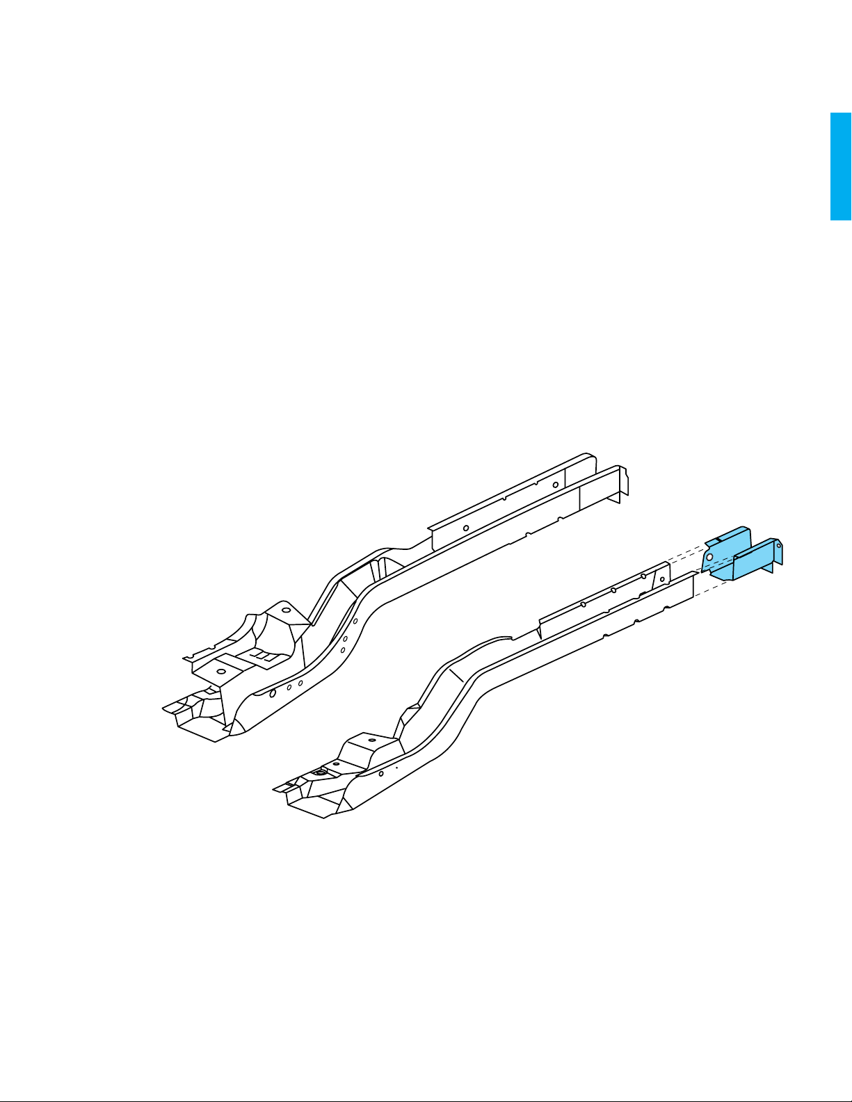
Rear Rail Sectioning
The rear rail is available as a complete assembly. It consists of an
outer panel, two inner reinforcements, a rail extension, and all
necessary component mounting brackets (Fig. 1-20). The outer
panel and rear mounting brackets are also available separately to
facilitate sectioning. Additionally, there is a crossbar that connects
the two rear rails for added strength and rigidity.
Complete rear rail replacement can be performed by drilling out all
the factory welds. The outboard flange at the forward end of the
rail must be cut in one location and bent upward, and the bottom
flange of the crossbar must be bent downward. The rear rail can
then be lowered from the vehicle (see Fig. 1-21). When installing
the service rail, the outboard flange must be cut and bent up, installed, then straightened, and aligned. Weld as necessary.
Rear rail sectioning procedures can be used to repair the rear rail if
just the portion rearward of the crossbar is damaged. The rear rail
outer panel is available separately for sectioning.
NOTE: The rail extension panel can also be purchased
separately.
Fig.␣ 1-20 — Rear Rail Panels
2000 cadillac deville 1-13
Page 15

Removal Procedure
1. Visually inspect and restore as much of the
damage as possible to factory specifications.
2. Remove all related panels and components.
3. Cut the rear rail along the rearward flange of
the crossbar (Fig. 1-21). Continue this cut
around the rear rail.
4. Drill out the factory welds on the end of the
rear rail inner reinforcement and extension.
5. Remove the damaged portion of the rear rail
and rail extension.
6. Either move the end of the rear rail inner rein-
forcement forward, or cut this part and remove
it from the rear rail.
1-14 2000 cadillac deville
Fig.␣ 1-21 — Full Rail Replacement
Page 16

FRT
Fig.␣ 1-22 — Cut the Rail for Sectioning
Fig.␣ 1-23 — Create Tabs on the New Rail
Section
Installation Procedure
1. Using the original part as a guide, mark a line
on the service rail 35␣ mm (1-5/16␣ in) forward
of the cut made to the original part; this
should be approximately 535␣ mm (21␣ in)
without the extension attached to the rail. This
will provide an overlap for welding the service
section (see Fig. 1-20).
2. Cut the service rail along the marked lines
and discard the unused section (Fig. 1-22).
3. Cut and remove approximately 35␣ mm
(1-5/16␣ in) of the flanges on the service-rail.
Cut a 5␣ mm (1/4␣ in) gap approximately
35␣ mm (1-5/16␣ in) along the corners of
the service rail to create tabs (Fig. 1-23).
4. Step the tabs inward to allow the service rail
to fit inside the original rail (Fig. 1-24).
5. Position the modified service rail inside the
original rail, allowing 35␣ mm (1-5/16␣ in)
of overlap.
6. Check the position of the service rear rail
section using three-dimensional measuring
equipment and tack weld in three locations
along all three sides of the rail (Fig. 1-25).
Stitch weld along the entire seam and replace
factory welds as necessary.
7. Drill two 8␣ mm (5/16␣ in) holes for plug
welding in each of the three sides of the rail
approximately 30␣ mm (1-3/16␣ in) from the
sectioning joint, plug weld through the drilled
holes into the service rail.
8. Clean and prepare welded surfaces.
IMPORTANT: Prior to refinishing, refer to
the publication GM4901M-D-2000 “GM
Approved Refinish Materials” for
recommended products. Do not combine
paint systems. Refer to manufacturer’s
recommendations.
9. Apply sealers and anti-corrosion materials as
necessary.
10. Prime with two-part catalyzed primer.
11. Install all related components.
Fig.␣ 1-24 — Step Tabs Inward on the New Rail
Section
FRT
Fig.␣ 1-25 — Install the New Rail Section
2000 cadillac deville 1-15
Page 17

Engine Compartment Dimensions – 2000 Cadillac
DeVille
Ø
A
B
C
ZERO
LINE
19 MM
GAGE
HOLE
F
ALL LENGTHS MEASURED
E
Description Location Length Width Height
Strut mount hole A 367 565 1014
Strut mount hole B 509 575 1029
Strut mount hole C 437 693 1027
Bumper mount hole D 1273 603 520
Bumper mount hole E 1273 605 640
Fender mount hole F 12 774 368
All dimensions are measured in millimeters, from a zero line, center line, and a common datum. All dimensions are symmetrical, unless otherwise specified.
D
FROM Ø LINE AT TOP
HINGE 19 MM HOLE
ALL MEASUREMENTS
HOLE CENTER TO CENTER
1-16 2000 cadillac deville
Page 18

Underbody Dimensions – 2000 Cadillac DeVille
Ø
540
WIDTH
504
427
430
496
553
577
HEIGHT
LENGTH
469 552 526
B
A
925
1092
C
888
348 358 537 496
D
1752
2537
E
F
3191
G
Description Location Length Width Height
28 mm mounting nut A 1092 540 469
19 mm x 25 mm gage slot B 925 504 552
16 mm gage hole C 0 427 526
19 mm gage hole D 888 430 348
23 mm gage hole E 1752 496 358
Top spring mounting pad F 2537 553 537
19 mm x 25 mm gage hole G 3191 577 496
All dimensions are measured in millimeters, from a zero line, center line, and a common datum. All dimensions are symmetrical, unless otherwise specified.
DATUM LINE
2000 cadillac deville 1-17
Page 19

Body Side Dimensions – 2000 Cadillac DeVille
ø
A
WIDTH
HEIGHT
LENGTH
829
836
591 930964 665 1004
0
B
0
1140
1140
840
849
C
D
E
2183
827
DATUM LINE
F
Description Location Length Width Height
19 mm gage hole A 0 — —
19 mm gage hole B 0 836 591
19 mm gage hole C 0 829 930
19 mm gage hole D 1140 840 964
Lower hinge bolt hole E 1140 849 665
16 mm upper latch mounting hole F 2183 827 1004
All dimensions are measured in millimeters, from a zero line, center line, and a common datum. All dimensions are symmetrical, unless otherwise specified.
1-18 2000 cadillac deville
 Loading...