

Page 1

CADILLAC
OPERATOR'S
MANUAL
EDITION
NO.
355-CX1
In
ordering
a duplicate of
this
Manual
specify the
above
number or the engine number of the car.
Page 2

Table
of
Contents
CHAPTER
I—Cadillac
Service
3
Cadillac-La
Salle Service Stations—Identification
Card—Care
of the
Car—Authorized
Service—Preventive Service—Repair Parts—Service
Charges—Flac Rate Service—Standard Service Contract—Lubrication
Agreement.
CHAPTER
II—Lubrication 11
Lubrication
Schedule—Lubrication
Notice—LUBRICANTS—Engine
Oil—Transmission
Lubricant—Rear Axle Lubricant—Steering Gear
Lubricant—Chassis
Lubricant—Clutch
and Wheel Bearing Lubricant—
Water
Pump
Lubricant—ENGINE
LUBRICATION—Oil
Level—Crank-
case
Ventilating
System
and Oil Filter—Changing Engine
Oil.
CHAPTER
III-—Operation
18
Gasoline Gauge—Oil Pressure Gauge—Ammeter—Temperature Indicator—Throttle Control—Choke Control—Starting
the
Car—Starting
Hints—Ride
Regulation—Lighting Switch—DRIVING
HINTS—
Speed—Gravel Roads—Hills—Slippery Roads—Danger of Running
Car
in
Closed Garage.
CHAPTER
IV—Cold
Weather
Operation
26
PREPARING
FOR
COLD
WEATHER—Anti-Freezing
Solutions-
Winter
Lubrication—Storage Battery— Gasoline
System—STARTING
THE
ENGINE—Choke
Button—Position
of
Throttle Hand Lever-
Priming
the
Carburetor—Use
of
Starter—Use
of
Accelerator Before
Engine
is
Warm.
CHAPTER
V—Equipment . . . 32
Locks
and Keys—Ignition Switch Lock—Door Locks—Package
Com-
partment—Interior Lights
and
Switches—No-Draft Ventilation—
Windshield Cleaner—Sun Visor—Adjustable Seat—Cigar Lighter—
Tools—Tires—Use
of
Jack—Spare Wheel Carrier—Changing Wheels.
CHAPTER
VI—General
Care
42
Storage
Battery—Generator Charging Rate—Spark Plug—Cooling
System—Gasoline System—Carburetor Air Cleaner—Brakes—Tires—
Removing Tires from Wheels—Tire Balancing
Marks—Lights—Replac-
ing Map Lamp Bulb—Aiming
the
Headlamps—Storing
the
Car—
BODY—Care
of the
Finish—Care
of the
Top—Cleaning Upholstery
—Door
hardware—Body Adjustments.
CHAPTER
VII—Specifications and
License
Data
59
[2]
CHAFTER4_;<f
«W
CADILLAC
SERVICE
T
HE
OWNER
of
a Cadillac
motor
car has
purchased a fine
piece
of
machinery
to
serve
him as a
pleasant
and
dependable
means
of
transportation.
The
Cadillac
provides
this
means;
pleasant
because
of its
fine
performance,
comfort
and
ease of
con-
trol;
dependable
because
of the
care
with
which
it was
built
and
because
of
Cadillac
Service,
which
operates
on a
standard
policy,
guaranteeing
the
owner
efficient
service
everywhere
at
standard
prices
under
factory
regulation.
Cadillac-La
Salle
Ser-
vice
Stations
Cadillac
Service
is
available
wherever
Cadillac and La
Salle
cars
are
sold.
Service
stations
conducted
by
Cadillac distribu-
tors
and
dealers
are
designated
as "Authorized
Cadillac-La
Salle
Service
Stations,"
and are
identified
by the
exclusive
sign
shown
on
this
page.
Wherever
this
sign
is
displayed,
the
owner
will find an
organization
prepared
to
service
Cadillac
cars.
This
means
proper
equipment,
factory-trained
personnel,
a
stock
of
genuine
replacement
parts
and
standardized
policies
and
methods.
Fif.l.
AuthorizedCadillac-LaSalle
Service
Stations
display
this
sign
at
the
service
entrance.
[31
Page 3

Table
of Contents
CHAPTER
I—Cadillac
Service
. 3
Cadillac-LaSalle
Service
Stations—Identification
Card—Care
of the
Car—Authorized
Service—Preventive Service—Repair Parts—Service
Charges—Flat Rate Service—Standard Service Contract—Lubrication
Agreement.
CHAPTER
II—Lubrication
11
Lubrication
Schedule—Lubrication Notice—LUBRICANTS—Engine
Oil—Transmission
Lubricant—Rear Axle Lubricant—Steering Gear
Lubricant—Chassis
Lubricant—Clutch
and Wheel Bearing Lubricant—
Water
Pump
Lubricant—ENGINE
LUBRICATION—Oil
Level—Crank-
case
Ventilating
System
and Oil Filter—Changing Engine
Oil.
CHAPTER
III—Operation 18
Gasoline Gauge—Oil Pressure Gauge—Ammeter—Temperature Indicator—Throttle Control—Choke Control—Starting the Car—Starting
Hints—Ride Regulation—Lighting Switch—DRIVING
HINTS—
Speed—Gravel Roads—Hills—Slippery Roads—Danger of Running
Car
in
Closed Garage.
CHAPTER
IV—Cold
Weather
Operation
26
PREPARING
FOR
COLD
WEATHER—Anti-Freezing
Solutions-
Winter
Lubrication—Storage Battery— Gasoline
System—STARTING
THE
ENGINE—Choke
Button—Position of Throttle Hand Lever-
Priming
the Carburetor—Use of Starter—Use of Accelerator Before
Engine is
Warm.
CHAPTER
V—Equipment
. . . 32
Locks
and Keys—Ignition Switch Lock—Door Locks—Package
Com-
partment—Interior Lights and Switches—No-Draft Ventilation—
Windshield Cleaner—Sun Visor—Adjustable Seat—Cigar Lighter—
Tools—Tires—Use of Jack—Spare Wheel Carrier—Changing Wheels.
CHAPTER
VI—General
Care
42
Storage
Battery—Generator Charging Rate—Spark Plug—Cooling
System—Gasoline System—Carburetor Air Cleaner—Brakes—Tires—
Removing Tires from Wheels—Tire Balancing Marks—Lights—Replac-
ing Map Lamp Bulb—Aiming the Headlamps—Storing the
Car—
BODY—Care
of the Finish—Care of the Top—Cleaning Upholstery
—Door hardware—Body Adjustments.
CHAPTER
VII—Specifications
and
License
Data 59
[2]
CHAPTER^
/<t£
fa
CADILLAC
SERVICE
* //^>r.
T
HE
OWNER
of a Cadillac
motor
car has purchased a
fine
piece
of machinery to
serve
him as a
pleasant
and
dependable
means
of transportation. The Cadillac
provides
this
means;
pleasant
because
of its
fine
performance, comfort and
ease
of con-
trol;
dependable
because
of the
care
with
which it was built and
because
of Cadillac
Service,
which
operates
on a standard
policy,
guaranteeing
the
owner
efficient
service
everywhere
at
standard
prices
under factory
regulation.
Cadillac-La
Salle
Ser-
vice
Stations
Cadillac
Service
is
available
wherever
Cadillac and La
Salle
cars
are sold.
Service
stations
conducted
by Cadillac distribu-
tors
and
dealers
are
designated
as "Authorized Cadillac-LaSalle
Service
Stations,"
and are
identified
by the
exclusive
sign
shown
on
this
page.
Wherever
this
sign
is displayed, the ^-
1
' Authorized
Cadillac-La
Salle
.„
_ , . . Service
Stations
display
this
sign
at
owner
will find an
organization
the
service
entrance.
prepared to
service
Cadillac
cars. This
means
proper
equipment,
factory-trained
personnel,
a
stock
of
genuine
replacement
parts
and standardized
policies
and
methods.
131
Page 4

1
9
Page 5
1
joe car
qy^^y^ist
and most frequent contact with
Cadillac
fServke
i|^(ij;irry
will
be in the service station of the distributor
fciQeJler
who sold
him
the
car and
who therefore has the
greatest
interest at stake in assuring him satisfaction.
Cadillac
Service is
so organized, however, that the owner may feel perfectly free to
use his
car
for extended travel, secure in the knowledge that other
Authorized
Cadillac-La
Salle Service Stations are able
and
willing
to offer the
same
service benefits to which he is entitled at his
local
service station.
Identification
Card
As
a means of introduction at other
Authorized
Cadillac-
La
Salle Service Stations, every purchaser of a
Cadillac
car is
given credentials in the
form
of an Identification
Card.
This
card
is mailed to the owner by the
Cadillac
Motor
Car
Company
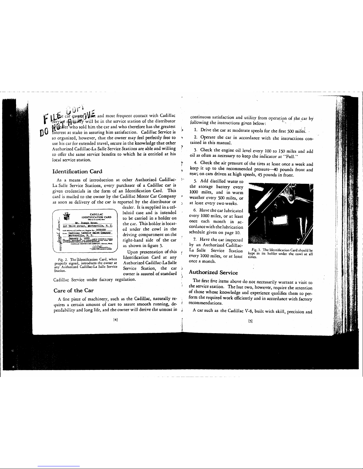
as soon as delivery of the car is reported by the distributor or
———^
dealer. It is
supplied
in a
cel-
luloid
case
and is intended
to be
carried
in a holder on
the
car.
This
holder
is located under the cowl in the
driving
compartment on the
right-hand
side of the car
as shown in
figure
3-
Upon
presentation of this
Identification
Card
at any
Authorized
Cadillac-LaSalle
Service
Station, the car
owner is assured of
standard
CADILLAC
IDENTIFICATION CARD
115 Third
Street.
MortoaYllle.
N. 1.
i
d.Hn.y
.1
Ca4iH.<
....
Ca«tii*
M~
5000000
»^SsiillS£_l»Salle SaiesJ&aiBKL-
Mortonvllle, II,
Y.
Sf „
Jsnuary
1, 1953 .„j,. „ _i„
£4 \ PROMPT, EFFICIENT
-nd
COURTEOUS
....1«
l.om
ANY
* A l/THORlZEO
CADILLAC
SERVICE
STATION-
CADILLAC
MOTOR CAR
COMPANY,
Ortrrtt.
Mich.
Fig.
2. The [Identification
Card,
when
properly
signed, introduces the owner at
any
Authorized
Cadillac-La
Salle Service
Station.
Cadillac
Service under factory regulation.
Care
of the
Car
A
fine piece of machinery, such as the
Cadillac,
naturally re-
quires
a certain amount of care to assure smooth
running,
de-
pendability
and
long life, and the owner
will
derive the utmost in
14]
continuous satisfaction and utility
from
operation of the car by
following
the instructions given below:
1.
Drive
the
car
at moderate
speeds
for the first 500 miles. •
2. Operate the car in accordance with the instructions con-
tained
in this
manual.
3.
Check
the engine oil level every 100 to 150 miles and add
oil
as often as necessary to keep the indicator at
"Full."
4.
Check
the air pressure of the tires at
least
once a
week
and
keep it up to the recommended pressure—40 pounds front and
rear;
on cars driven at high
speeds,
45 pounds in front.
5. Add distilled water to
the storage battery every
1000 miles, and in warm
weather every 500 miles, or
at
least
every two
weeks.
6.
Have
the
car
lubricated
every 1000 miles, or at
least
once each month in ac-
cordance
with
the
lubrication
schedule given on page 10.
7. Have the car inspected
by
an
Authorized
Cadillac-
La
Salle Service Station
every 1000 miles, or at
least
once a month.
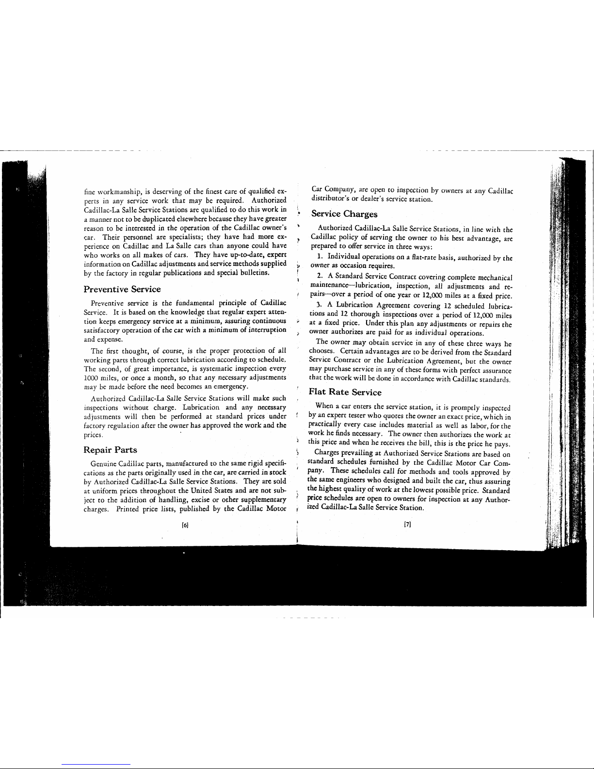
Fig.
3.
The
Identification
Card
should be
kept in its holder under the cowl at all
times.
Authorized
Service
The
first five
items
above do not necessarily warrant a visit to
the service station.
The
last two, however,
require
the attention
of
those
whose
knowledge and experience qualifies them to per-
form
the
required
work efficiently
and
in
accordance
with factory
recommendations.
A
car
such as the
Cadillac
V-8,
built with
skill,
precision and
151
Page 6

9
Page 7
fine
workmanship, is deserving of the finest care of qualified ex-
perts
in any service work
that
may be required. Authorized
Cadillac-La
Salle Service Stations are qualified to do this work in ''
t
a
manner not to be duplicated elsewhere
because
they have
greater
reason to be interested in the operation of the
Cadillac
owner's
v
car. Their personnel are specialists; they have had more experience on
Cadillac
and La Salle cars than anyone
could
have
who
works on all makes of cars. They have up-to-date, expert
information
on
Cadillac
adjustments and service methods supplied j>
by
the factory in regular publications and special bulletins. [
Preventive Service
i
Preventive service is the fundamental principle of
Cadillac
Service.
It is based on the knowledge
that
regular expert
atten-
tion
keeps emergency service at a minimum, assuring continuous >
satisfactory operation of the car
with
a minimum of interruption
and expense.
The
first thought, of course, is the proper protection of all
working
parts
through correct lubrication according to schedule.
The
second, of
great
importance, is systematic inspection every
1000
miles, or once a month, so
that
any necessary adjustments
may be made before the need becomes an emergency. <
Authorized
Cadillac-La
Salle Service Stations
will
make such
inspections without charge. Lubrication and any necessary
adjustments
will
then be performed at standard prices under '
factory
regulation after the owner has approved the work and the
prices.
'i
Repair
Parts t
}
Genuine
Cadillac
parts, manufactured to the
same
rigid
specifi-
cations as the
parts
originally
used in the car, are carried in stock
by
Authorized
Cadillac-La
Salle Service Stations. They are
sold
at uniform prices throughout the
United
States
and are not subject to the addition of handling, excise or other supplementary '
charges. Printed price lists, published by the
Cadillac
Motor
Car
Company, are open to inspection by owners at any
Cadillac
distributor's or dealer's service station.
Service
Charges
Authorized
Cadillac-La
Salle Service Stations, in line
with
the
Cadillac
policy
of serving the owner to his
best
advantage, are
prepared to offer service in
three
ways:
1. Individual operations on a flat-rate basis, authorized by the
owner as occasion requires.
2. A Standard Service Contract covering complete mechanical
maintenance—lubrication, inspection, all adjustments and repairs—over a period of one year or
12,000
miles at a
fixed
price.
3. A Lubrication Agreement covering 12 scheduled lubrica-
tions and 12 thorough inspections over a period of
12,000
miles
at a
fixed
price. Under this plan any adjustments or repairs the
owner authorizes are paid for as
individual
operations.
The owner may obtain service in any of
these
three
ways he
chooses. Certain
advantages
are to be derived from the Standard
Service
Contract or the Lubrication Agreement, but the owner
may purchase service in any of
these
forms
with
perfect
assurance
that
the work
will
be done in accordance
with
Cadillac
standards.
Flat
Rate Service
When
a car
enters
the service station, it is promptly inspected
by
an expert
tester
who
quotes
the owner an exact price,
which
in
practically
every
case
includes material as
well
as labor, for the
work
he finds necessary. The owner then authorizes the work at
this price and when he receives the
bill,
this is the price he pays.
Charges prevailing at Authorized Service Stations are based on
standard schedules furnished by the
Cadillac
Motor
Car
Com-
pany. These schedules
call
for methods and tools approved by
the
same
engineers who designed and built the car,
thus
assuring
the highest quality of work at the lowest possible price. Standard
price
schedules are open to owners for inspection at any Author-
ized
Cadillac-La
Salle Service Station.
[61
[71
Page 8

ft
Page 9

IN
Standard
Service
Contract
'
The
Standard
Cadillac
Service Contract is available to owners j
who wish to be assured of continuous satisfactory operation and v
maintenance of their cars at a predetermined, economical
cost.
^
It is based on Cadillac's principle of preventive service insuring
the
greatest
satisfaction with the
fewest
possible interruptions. f
Complete
lubrication on schedule and thorough inspection to j
anticipate the need of adjustment and repair largely eliminates
the need of service
between
regular inspections. *
The
Service Contract is recognized by all Authorized
Cadillac-
i
La
Salle Service Stations in the United
States
regardless of where
it may have been purchased. The owner is thus assured of all ,'
Contract
service due him without additional charge wherever
he may travel. He
needs
only to present the identification
card
issued to him at the time the
Contract
is purchased to receive this '
service the
same
as if the work was performed by the service >
station from which the
Contract
was purchased.
These contracts are available at all
Authorized
Service Stations.
Three
contracts are available to cover each of three periods; the
first year or first
12,000
miles, the second year or second
12,000
miles and the
third
year or
third
12,000
miles, respectively.
Owners
are urged to take advantage of the conveniences offered
by
Contract
ownership to obtain efficient and expert service under ,
factory regulations for their cars at the predetermined economical
1
cost.
'
Lubrication
Agreement
Owners
who do not purchase a Service Contract are urged to ^
purchase a
Lubrication
Agreement.
Lubrication
according to i
schedule is the most important attention required by the car
and
<
the
Lubrication
Agreement
assures
this service regularly over
a period of
12,000
miles at a saving of more than
30%
of the total
cost
of the
twelve
operations if
paid
for
individually.
i
The
Lubrication
Agreement is recognized by all Authorized i
Cadillac-La
Salle Service Stations in the United
States,
the
same
as the Service Contract, and the identification cardneed only be-'
presented to have the work scheduled performed at any/Authorized Service Station regardless of where the Agreement' was
purchased.
The
holder of a
Lubrication
Agreement is relieved of the
thought of lubrication
cost
during the entire
12,000
mile period
by
budgeting his
expense
beforehand. He
needs
only take his car
to the service station at monthly or 1000 mile intervals and
request "schedule lubrication" to obtain all of the lubricarion
due, performed according to factory specifications.
Regardless of how the owner prefers to have the
necessary service performed on his car, the surest
guarantee of long life and complete motoring
satis-
faction at the
least
possible
expense
is correct
lubrication and preventive service rendered every 1,000 miles
or
once
a month by an Authorized
Cadillac-La
Salle
Service Station.
18]
19]
Page 10

1
Page 11
OWNEF
ADORE
ENG1N
LUBRICATION
SCHEDULE
CADILLAC
355-C
'S
MAMJT
OWNEF
ADORE
ENG1N
OWNEF
ADORE
ENG1N
E
NO
DATF
DPI
ivpnrn
OO NOT
WAIT
FOR
SCM&OULt
LUBRICATIONS
BEFORE ADDING ENGINE OIL.
THE
OIL. LEVEL
SHOULD BE
CHECKED
EVERT
109
TO
1*0
MILES
ANO
OIL
ADDED
IF THE
IHOtCATOR
CALL \%
BELOW
"FULL."
THIS
IS
ESPECIALLY IM-
PORTANT ON
CARS
DRIVEN
AT
HIGH
SPEEDS.
LUBRICANT
LUBRICATION
NO. AND MILEAGE AT
WHICH
DUE
OO NOT
WAIT
FOR
SCM&OULt
LUBRICATIONS
BEFORE ADDING ENGINE OIL.
THE
OIL. LEVEL
SHOULD BE
CHECKED
EVERT
109
TO
1*0
MILES
ANO
OIL
ADDED
IF THE
IHOtCATOR
CALL \%
BELOW
"FULL."
THIS
IS
ESPECIALLY IM-
PORTANT ON
CARS
DRIVEN
AT
HIGH
SPEEDS.
LUBRICANT
1
*
4
< I
• •
ta II
OO NOT
WAIT
FOR
SCM&OULt
LUBRICATIONS
BEFORE ADDING ENGINE OIL.
THE
OIL. LEVEL
SHOULD BE
CHECKED
EVERT
109
TO
1*0
MILES
ANO
OIL
ADDED
IF THE
IHOtCATOR
CALL \%
BELOW
"FULL."
THIS
IS
ESPECIALLY IM-
PORTANT ON
CARS
DRIVEN
AT
HIGH
SPEEDS.
LUBRICANT
1 1 1 1
i
I I
000«
I
100001
1
I
0
z
<
0
z
z
0
<
0
z
as
D
J
«i
O
z
<
(ft
0
z
z
0
<
o
tz
a
0
J
| LUBRICATION NOS.
2,
4.
8
ANO
10
0
Z
<
tl)
0
z
z
0
h
<
0
IT
tn
0
-J
ADO
LIQUID
TO
RADIATOR
WATER
OR
ANTI.
FREEZE
O
0
O o o
O
0
o
O O O O
0
z
<
0
z
z
0
<
0
z
as
D
J
«i
O
z
<
(ft
0
z
z
0
<
o
tz
a
0
J
| LUBRICATION NOS.
2,
4.
8
ANO
10
0
Z
<
tl)
0
z
z
0
h
<
0
IT
tn
0
-J
ADD
ENGINE
OIL
AS
NECESSARY
ENGINE
OIL
o
O
O
o o o
0
z
<
0
z
z
0
<
0
z
as
D
J
«i
O
z
<
(ft
0
z
z
0
<
o
tz
a
0
J
| LUBRICATION NOS.
2,
4.
8
ANO
10
0
Z
<
tl)
0
z
z
0
h
<
0
IT
tn
0
-J
STMtTEB.
GENERATOR
*Ht>
DISTRIBUTOR
Oft
CUPS
BRAKE
AND
RIDf
REGULATOR
PINS
AND
CONNECTIONS
BME^EEEEEEEEEEl
•HHEEEEEEEEEEEEi
0
z
<
0
z
z
0
<
0
z
as
D
J
«i
O
z
<
(ft
0
z
z
0
<
o
tz
a
0
J
| LUBRICATION NOS.
2,
4.
8
ANO
10
0
Z
<
tl)
0
z
z
0
h
<
0
IT
tn
0
-J
ACCELERATOR
ROCKER
SHAFT
O
o o o O
o o
O
O
E
O
El
0
z
<
0
z
z
0
<
0
z
as
D
J
«i
O
z
<
(ft
0
z
z
0
<
o
tz
a
0
J
| LUBRICATION NOS.
2,
4.
8
ANO
10
0
Z
<
tl)
0
z
z
0
h
<
0
IT
tn
0
-J
DOOR
HAROWARE
FNGINE
OIL
o o o o
O
O
O O O O
o o
0
z
<
0
z
z
0
<
0
z
as
D
J
«i
O
z
<
(ft
0
z
z
0
<
o
tz
a
0
J
| LUBRICATION NOS.
2,
4.
8
ANO
10
0
Z
<
tl)
0
z
z
0
h
<
0
IT
tn
0
-J
OREASE
GUN
CONNECTIONS
LUBRICANT
o o
o O O
O
O O O
o
O
o
0
z
<
0
z
z
0
<
0
z
as
D
J
«i
O
z
<
(ft
0
z
z
0
<
o
tz
a
0
J
| LUBRICATION NOS.
2,
4.
8
ANO
10
0
Z
<
tl)
0
z
z
0
h
<
0
IT
tn
0
-J
WATER
PUMP
GREASE
CUP
WATER
PUMP
LUBRICANT
o o o
O
O
O
O
o
O
o
O O
0
z
<
0
z
z
0
<
0
z
as
D
J
«i
O
z
<
(ft
0
z
z
0
<
o
tz
a
0
J
| LUBRICATION NOS.
2,
4.
8
ANO
10
0
Z
<
tl)
0
z
z
0
h
<
0
IT
tn
0
-J
CLUTCH
RELEASE
FORK
WHEEL
BLARING
LUBRICANT
o
o o
o
O
o
O O
o
O O
o
0
z
<
0
z
z
0
<
0
z
as
D
J
«i
O
z
<
(ft
0
z
z
0
<
o
tz
a
0
J
| LUBRICATION NOS.
2,
4.
8
ANO
10
0
Z
<
tl)
0
z
z
0
h
<
0
IT
tn
0
-J
•ADD
WATER
TO
STORAGE
BATTERY
OIS
TILLED
o
o
o
o
a
o
o
O O
o
O
O
0
z
<
0
z
z
0
<
0
z
as
D
J
«i
O
z
<
(ft
0
z
z
0
<
o
tz
a
0
J
| LUBRICATION NOS.
2,
4.
8
ANO
10
0
Z
<
tl)
0
z
z
0
h
<
0
IT
tn
0
-J
CHECK
TIRE
INFLATION
ESEEEEEEESE3
0
z
<
0
z
z
0
<
0
z
as
D
J
«i
O
z
<
(ft
0
z
z
0
<
o
tz
a
0
J
| LUBRICATION NOS.
2,
4.
8
ANO
10
DRAIN
ANO
REPLACE
ENGINE
OIL
.NGINI-.
OIL
•
o
•
o
• O • O •
O
•
o
0
z
<
0
z
z
0
<
0
z
as
D
J
«i
O
z
<
(ft
0
z
z
0
<
o
tz
a
0
J
| LUBRICATION NOS.
2,
4.
8
ANO
10
CLUTCH
RELEASE
BEARING
WHEEL
HEARING
LUBRICANT
o
o
o
O O
o
0
z
<
0
z
z
0
<
0
z
as
D
J
«i
O
z
<
(ft
0
z
z
0
<
o
tz
a
0
J
TRANSMISSION—M>0
LUBRICANT
TRANSMISSION
LUBRICANT
o O
O
o
0
z
<
0
z
z
0
<
0
z
as
D
J
«i
O
z
<
(ft
0
z
z
0
<
o
tz
a
0
J
REAR
AXLE—ADD
LUBRICANT
REAR A ALE
LUBRICANT
o O
O
o
0
z
<
0
z
z
0
<
0
z
as
D
J
«i
O
z
<
(ft
0
z
z
0
<
o
tz
a
0
J
STEERiNO
GEAR—ADD
LUBRICANT
STEERING
GEAR
LUBRICANT
O O
O
O
0
z
<
0
z
z
0
<
0
z
as
D
J
BRAKE
ASSISTER
LIGHT
MACHINE
Oil.
O
o
0
z
<
0
z
z
0
<
0
z
as
D
J
SFRINO
COVERS
GEAR
LUBRICANT
O
O
0
z
<
0
z
z
0
<
0
z
as
D
J
WHEEL
BEARINGS
WHEEL
BEARING
LUBRICANT
O
O
0
z
<
0
z
z
0
<
0
z
as
D
J
S
PEEOO
METER
OR
IVE
SHAFT
LUBRICANT
O
O
0
z
<
0
z
z
0
<
0
z
as
D
J
"REFILL
SHOCK
ABSORBERS
SFECIAL
OIL
O
o
0
z
<
0
z
z
0
<
0
z
as
D
J
"CLEAN
CARBURETOR
AIR
CLEANER
O
o
0
z
<
0
z
z
0
<
0
z
as
D
J
"FLUSH
COOLING
SYSTEM
AND
ADO INHIBITOR
O
o
••REPLACE
OIL FILTER
CARTRIOGE
CLEAN
OIL PAN ANO
SCREEN
EVERY
12.O00
MILES
o
•IN
SUMMER
INSPECT
BATTER*
INVERT
IOO
MILES
OR AT
LEAST
EVERT t WEEKS,
"RECOMMENDED
BUT NOT
INCLUDED
IN
LUBRICATIONS
• AND
II.
THE
FOLLOWING
OPERATIONS
CANNOT
BE PLACED ON A
MILEAGE
BASIS
AND ARC NOT
INCLUDED
IN)
THE
ABOVE
SCHEDULE;
CHANGE
REAR
AXLE
AND
TRANSMISSION
LUBRICANT—At
REQUIRED
FOR LOW
TEMPERATURES
IM
FALL
OR
WINTER ANO AT
BEGINNING
OF
MILD
WEATHER
"N
SPRING.
RECORD
ON
OTHER
SIDE
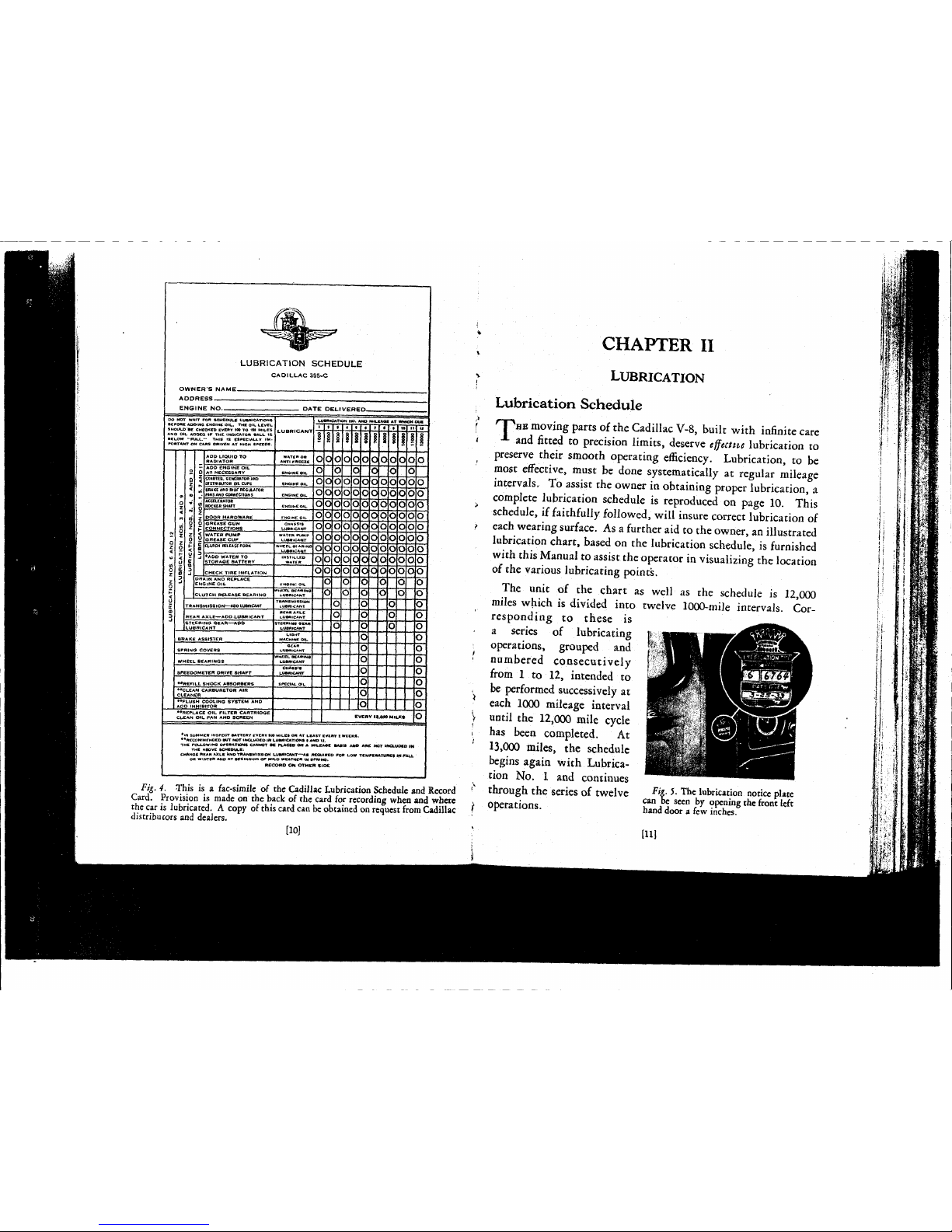
Fig.
4. This
is a
fac-simile
of
the Cadillac Lubrication
Schedule
and Record
Card.
Provision
is
made
on the back
of
the card for recording
when
and
where
the car is lubricated. A copy
of
this
card can be
obtained
on
request
from Cadillac
distributors
and
dealers.
[10]
CHAPTER
II
LUBRICATION
Lubrication
Schedule
T
HE
moving parts of the
Cadillac
V-8,
built with infinite care
and
fitted
to
precision limits,
deserve
tffectne
lubrication
to
preserve their
smooth
operating efficiency. Lubrication,
to be
most
effective,
must
be
done
systematically
at
regular
mileage
intervals, To
assist
the owner in obtaining proper lubrication,
a
complete
lubrication
schedule
is
reproduced on
page
10. This
schedule,
if faithfully followed, will insure correct lubrication of
each
wearing surface. As a further aid to the owner, an illustrated
lubrication chart,
based
on the lubrication
schedule,
is furnished
with
this
Manual
to
assist
the operator in visualizing the location
of the various lubricating points.
The
unit
of
the
chart
as
well
as
the
schedule
is
12,000
miles
which is divided into
twelve
1000-mile
intervals.
Cor-
responding
to
these
is
a
series
of
lubricating
operations, grouped
and
numbered
consecutively
from
1 to
12,
intended
to
be performed
successively
at
each
1000
mileage
interval
until
the
12,000
mile
cycle
has
been
completed.
At
13,000
miles,
the
schedule
begins
again with
Lubrica-
tion No. 1 and
continues
through the
series
of
twelve
Fi£-J
-
The lubrication
notice
plate
.
can
be
seen
by
opening
the
front
left
Operations. hand
door
a few
inches.
[11]
Page 12

Lubrication
Notice
^
|Arnetal
plate in the shape of the
Cadillac
Crest is provided to
|\y
serve as a lubrication
notice
and
record.
This
plate is mounted on
y
the left front door
pillar
just below the top hinge as shown in
figure
5.
Authorized
Cadillac-La
Salle Service Stations, after
performing
each schedule
operation,
post on this plate the
number
of the next
operation
and the mileage at which it
will
be due.
Thus,
when
the mileage
recorded
on
the speedometer is the same as the mileage
marked
on the notice, the car may be taken to any
Authorized
Cadillac-La
Salle Service Station, and, without further ordering
other than specifying "schedule
lubrication,"
the
car
will
receive
the exact
lubrication
necessary.
Although
the schedule is expressed in terms of miles the car
should
be lubricated once each month even though the mileage
indicated
on the speedometer is
less
than
1000
since the last
lubrication
operation was performed. The
lubrication
work can
be done while the car is in the service station for its regular
monthly
or
1000
mile inspection.
Lubricants
The
selection of proper lubricants should be one of the first
concerns of the owner in his attention to the lubrication of the
car.
The lubricants must not only be of high quality but their
viscosity and other characteristics must be suited to the purpose
for
which they are to be used.
Cadillac
engineers have worked out in detail the specifications
for
the lubricant required for each point to
meet
the particular
conditions of speed, load, temperature and
kind
of metals in
contact.
Authorized
Cadillac-La
Salle Service Stations are prepared to
furnish
lubricants under
these
specifications to give the
best
re-
sults
in their respective localities.
When
the car is
lubricated
by
[12]
someone not familiar with
Cadillac
specifications, lubricants
should
be
called
for
by
the
S. A. E.
viscosities
recommended
in
the
following
paragraphs.
Engine
Oil
Engine
oil recommendations are given in the chart below. It
should
be noted that different grades of oil are to be used for
average
driving
and for prolonged high speed
driving
in both
summer
and
winter.
SUMMER
WINTER
TYPE
OF
TYPE
OF
SERVICE
AH
Temperatures
Above
32°
F.
Between
32°
and
Below
15°
Above
AH
Temperatures
Above
32°
F.
15°
Above
Zero
AVERAGE
S.
A. E.
S.
A. E.
S.
A. E.
DRIVING
vise. 40
vise. 20
vise
10
(No prolonged
or
50
(No prolonged
or
50
high
speed
These
oils
are not
suitable
for
prolonged
driving)
high
speed
driving
and if
used
under
such
driving)
conditions
the oil
levil mart
1»
watched,
as the
rate
be
higher
than
with
heavier
oils.
CADILLAC
APPROVED "HEAVY DUTY" OILS-
SUMMER
AND
WINTER
These oils have an S. A. E. viscosity of
40-50-60,
and are
required
to
meet
certain specifications as to volatility in
order
to demonstrate their
fitness
for prolonged high speed
Idriving.
To make certain of using an oil approved for this
service, consult your
Cadillac
distributor or dealer,
j
NOTE:
Approved
heavy duty oils vary in their suita-
bility
for winter use. If an approved heavy duty oil with
sufficiently low cold viscosity is not available and if the car
is not kept in a heated garage, the lighter oils specified
jabove for average
driving
must be used to avoid
hard
start-
ling.
In this
case,
be sure to watch the oil level closely as
cautioned above.
f.
^V7"
601
u,sed
in
fable t0
designate
body
or
viscosity
is
the one
d™-!™™!
by
the Society
of
Automotive
Engineers^
adopted
by
alToU
compares
1¾
the place : of the old mdefinite method of describing oils as "St "
"Medium
"
arte /
tC
- °i
Sh°Uld
•*
Called
for
h
r
^numbers. If a
fillings
taSon
lS^d0?-
n0t
kn°W
S- A- E
Dambas
°
f his
*c
followinggfadS"an
PROLONGED
HIGH SPEED
DRIVING
[131
Page 13
Transmission
Lubricant
Gear
oil of S. A. E. viscosity 160 should be used in the trans-
mission at temperatures above 20° F. For temperatures below
20°
F,
a light oil of S. A.
E.
viscosity 90 should be used or the oil
used during summer weather should be thinned with kerosine.
Some of the lubricants designated by
"EP"
following their
S. A.
E.
classification, and
some
other lubricants which are being
marketed,
are injurious to bronze parts and should not be used in
Cadillac
cars under any circumstances. Likewise,
soap
greases
will
not satisfactorily lubricate
these
gears
and should not be
used.
Rear
Axle
Lubricant
Gear
lubricant of S. A. E. viscosity 160 should be used in the
rear
axle. For extremely low temperatures, it may be necessary
to change to a light lubricant of S. A. E. viscosity 90 or to thin
the lubricant with kerosine as
suggested
under "Transmission
Lubricants."
Steering
Gear
Lubricant
The
selection of the proper lubricant for the steering gear is of
special importance, particularly to avoid
hard
steering in cold
weather. A special steering gear lubricant suitable for extreme
heat
and cold is available and should be used in the steering gear
the year
round.
Chassis
Lubricant
A
good
grade of
chassis
lubricant
should be used for all
chassis
points indicated in the lubrication chart as requiring this type of
lubricant.
Ordinary
cup
grease
is not satisfactory and if, in an
emergency, it is used in place of
chassis
lubricant,
the
car
should
again be lubricated within 300 or 400 miles.
Clutch
and
Wheel
Bearing
Lubricant
The
front wheel bearings and the clutch
release
bearingshould
be
lubricated with a good grade of
Clutch
and Wheel Bearing
[141
Lubricant
having a high melting point.
Ordinary
grease
at
these
points is likely to melt and run on to the brakes or the
clutch.
Water
Pump
Lubricant
A
water-resistant
calcium
soap
lubricant
having a high melting
point is recommended for use in the water pump
grease
cup.
Only
lubricants of this type should be used; other
lubricants
will
be dissolved into the cooling
system
liquid.
Cup
greases
and
wheel bearing lubricants are entirely unsuited for this purpose.
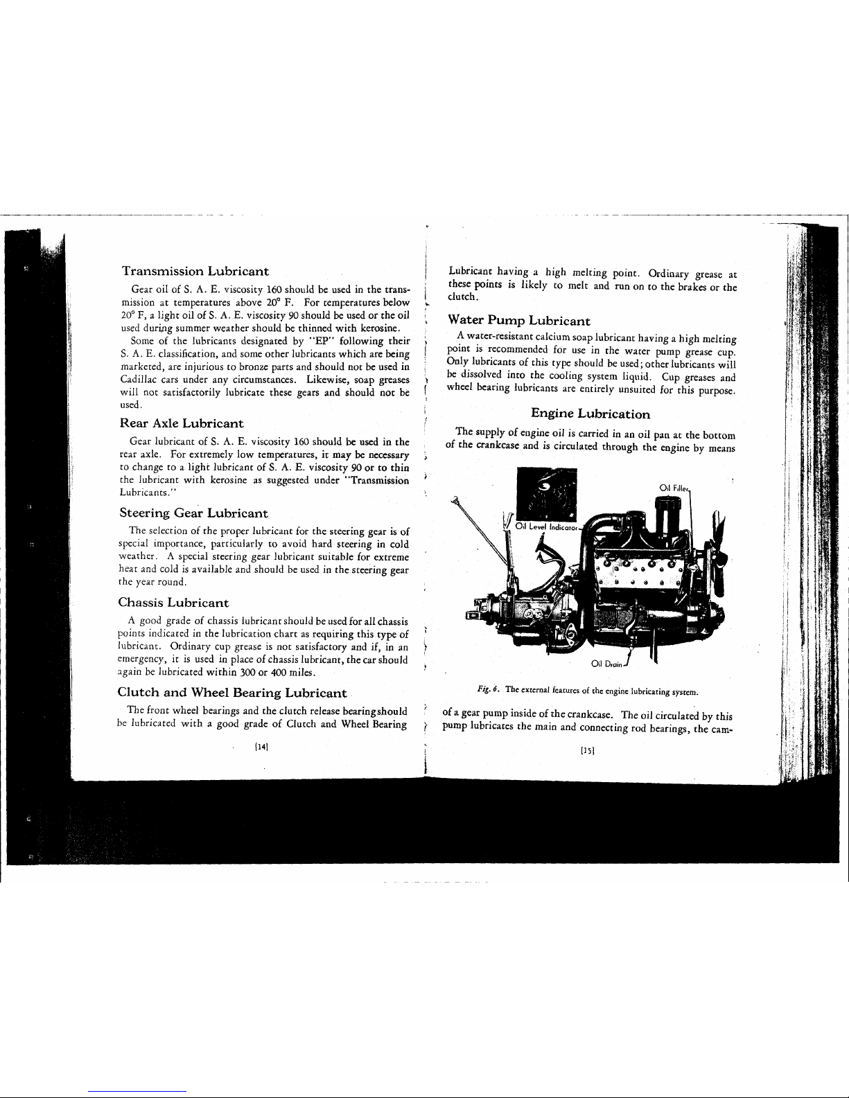
Engine
Lubrication
The
supply of
engine
oil is carried in an oil pan at the bottom
of
the crankcase and is circulated through the
engine
by means
Fig.
6. The external features of the
engine
lubricating system.
of a gear pump inside of the crankcase. The oil circulated by this
pump
lubricates the main and connecting rod bearings, the cam-
[15]
Page 14
shaft bearings, the
cylinder
walls, the pistons and the piston pins,
the front end chains, the valve mechanism and the fan.
There
are a few points on the engine that cannot be taken care
of
by the pressure system and
these
points should be lubricated
according
to the instructions given in the
lubrication
chart.
This
includes the starting motor, the generator, the distributor and
the water pump.
Oil
Level
The
normal
capacity of the oil pan is eight
quarts
which
fills
it
to the level of the screen in the pan.
When
the oil pan contains
this amount the oil level indicator
between
the two blocks at
the rear of the engine (figure 6)
shows
"Full."
The oil level
should
be checked every 100 to 150 miles and, whenever
neces-
sary,
enough oil should be added to
bring
the indicator up to
"Full."
It should never be permitted to drop below
"Fill."
Particular
attention should be
paid
to the oil level in
case
of
prolonged
driving
at high speed. At high
speeds
the oil is con-
sumed many times as
rapidly
as at city
driving
speeds
and oil
must be added more frequently to maintain the
proper
level.
Crankcase
Ventilating System and
Oil
Filter
Cadillac
V-8
engines
are equipped with a crankcase ventilating
system and an oil filter to keep the oil in the
best
condition
possible.
The
ventilating system,
which
functions automatically,
prevents dilution and contamination of the oil by removing the
vapors which
seep
past the pistons.
The
oil filter removes
dirt
and solid matter
from
the oil
until
it gradually
becomes
so clogged that it
ceases
to function. The
filter
cartridge
must then be replaced.
Normally,
replacement
should
be at
12,000
miles. The oil pan and screen should be
removed
and thoroughly washed with gasoline every
12,000
miles to remove any carbon or foreign particles that may
have collected.
116]
Changing
Engine
Oil
The
useful life of the engine oil is greatly prolonged by the use
of
the crankcase ventilating system and the oil filter, but the oil
pan
should be drained and the engine oil replaced every
2000
miles. To
drain
the oil, simply remove the
drain
plug (figure 6)
and
allow the oil to flow into a receptacle placed under the car.
The
drain
plug should then be reinstalled and tightened securely
before pouring in fresh
oil.
Eight
quarts are required to
bring
the oil level indicator to
"Full."
1171
Page 15
CHAPTER
III
OPERATION
O
NE
of the first things the
driver
of the
Cadillac
V-8
should do
is to familiarize himself with the location and use of the
instruments and controls described in this chapter.
Gasoline
Gauge
The
gauge
marked
"Gasoline" indicates
in
gallons the quantity
of
fuel in the tank at the rear of the car.
This
gauge
operates
electrically
and
indicates
the quantity of fuel
only
tvhen
the
ignition
is
turned
on.
When the tank is
being filled and the
driver
wishes
to check
the amount of fuel in
the tank, he should first
shut off the
engine
to
comply
with filling
station regulations and
then switch on the igni-
tion so that the
gauge
will
operate.
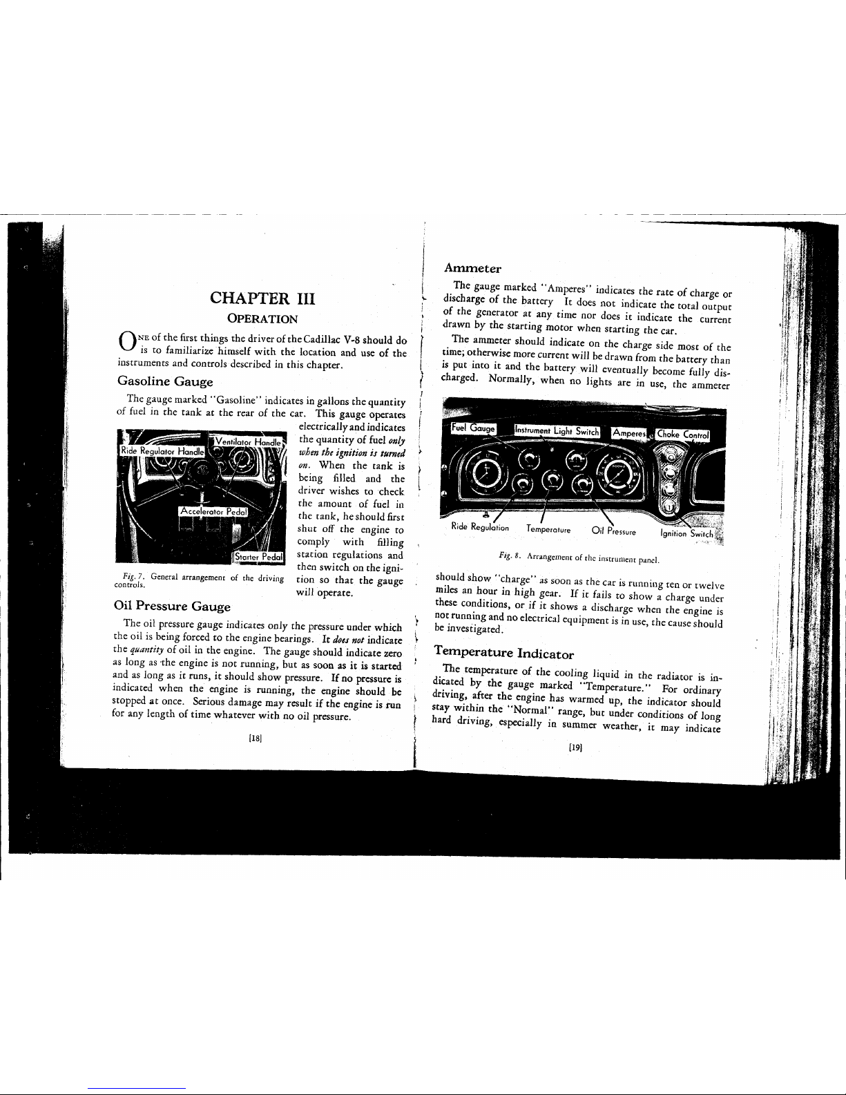
Fig.
7. General arrangement of the
driving
controls.
Oil
Pressure Gauge
The
oil pressure
gauge
indicates only the pressure under which
the oil is being forced to the
engine
bearings. It
does
not
indicate
the
quantity
of oil in the engine. The
gauge
should indicate zero
as long as the
engine
is not running, but as soon as it is started
and
as long as it runs, it should
show
pressure. If no pressure is
indicated when the
engine
is running, the
engine
should be
stopped at once. Serious damage may result if the
engine
is fun
for
any length of time whatever with no oil pressure.
[181
Ammeter
The
gauge
marked "Amperes" indicates the rate of charge or
discharge of the battery It
does
not indicate the total output
of
the generator at any time nor
does
it indicate the current
drawn
by the starting motor when starting the car.
The
ammeter should indicate on the charge
side
most of the
time; otherwise more
current
will be
drawn
from the battery than
is put into it and the battery will eventually become fully dis-
charged.
Normally, when no lights are in use, the ammeter
Ride
Regulation
Temperature
Oil
Pressure
Igninon
Sw.tch
;
Fig.
8.
Arrangement of the instrument panel.
should
show
"charge" as soon as the car is
running
ten or
twelve
miles an hour in high gear. If it fails to
show
a charge under
these
conditions, or if it
shows
a discharge when the
engine
is
not
running
and
no electrical equipment is in use, the
cause
should
be investigated.
Temperature
Indicator
The
temperature of the cooling
liquid
in the radiator is in-
dicated by the
gauge
marked "Temperature." For ordinary
driving,
after the
engine
has warmed up, the indicator should
stay
within the
"Normal"
range, but under conditions of long
hard
driving,
especially in summer weather, it may indicate
[19]
Page 16

r
»
Page 17

"Hoc."
This
is to be ex|
efficient operation of the
Fig.
9. The hood ports may be
opened by
pulling
out on the
wind-
splits.
opened by simply
pulling
out on
Throttle
Control
The
throttle of the
carburetor
is
controlled by a hand lever and
a
foot pedal or accelerator. The
normal
position of the hand
lever for
driving
the car is all
the way up to
"CLOSED."
In
this position the throttle of the
carburetor
is open just enough
to permit the engine to run at
idling
speed after it is
warm.
For
starting, however, the lever
should
be moved approximately
ed and
will
not interfere with
gine. If it indicates "Hot"
after short runs and under
average operating conditions,
however, the
cause
should be
investigated. The temperature
indicator
will
always show a
temporary
rise in temperature
immediately
after stopping the
engine.
This
likewise is a
natural
condition and is due
to the residual heat in the
engine.
For
average operation in
warm
weather, the hood ports
should
be open.
Ordinarily,
these
ports should be opened
at the start of
warm
weather in
the spring and left open
until
the beginning of cold weather
in
the
fall.
They
may be
the windsplits on the
hood
ports.
Fig.
10.
The throttle hand control
is the top lever on the hub of the
steering wheel.
[20]
one-fourth
the way down, and should be left in this position
until
the engine is
warm
enough to
permit
the
lever
to
be
returned
to the
idling
position without stalling the engine. (Also see
Chapter
on
"Cold
Weather
Operation.")
Carburetor
Choke
Control
Correct
use of the choke control is essential not only to
quick
starting
of the engine, but also has an
important
effect
on the life
of
the engine. The button must be pulled out far enough in
starting
to provide an explosive mixture
quickly
so that the
battery
is not unnecessarily discharged by
useless
cranking.
The
button
must also be left out far enough
during
the warming-up
period
so that the engine
will
run
without missing
and
"popping-
back."
On
the other
hand,
it should not be pulled out any further or
left out any longer than is necessary to accomplish
these
results,
because
some
of the
excess
liquid
gasoline in the
enriched
mixture
does
not
burn
and may wash off the oil on the cylinder walls,
interfering
with proper lubrication of the pistons. The button
should
be pushed all the way in as soon as this can be done with-
out causing "popping-back."
If
the engine still retains heat
from
previous
running,
the choke
control
should not be used without first attempting to start the
engine on the
normal
mixture. If the choke button is pulled out
for
starting a hot engine the mixture may be made so
rich
that
starting
will
be impossible.
The
choke button is not a
priming
device. It has no
effect
whatever on the fuel or the fuel
mixture
unless
the engine is being
cranked
or is
running
under its own power. To have any
effect,
it must be pulled out and kept partly out
during
the
cranking
operation.
Starting
the Car
To
start the car,
first
make sure the transmission is in neutral
[21]
Page 18

1.
«
Page 19

and
the
hand
throttle is in the normal starting position.
Then
pull
out the choke
(unless
the car is warm from previous
running),
switch on the ignition by turning the key to the
left
until
the lock cylinder springs out, and
step
on the starter.
As
soon as the
engine
starts,
release
the starter pedal and push
the choke button in as far as possible without stalling the engine.
When
the
engine
warms up,
push
the
choke
button
all
the
way in.
The
proper
use of the choke control will permit the
engine
to
run
smoothly until it warms up. The
engine
should never be raced
to warm it up. Racing
the
engine
is not only
a
\ unnecessary, but in-
Choke Control j effective.
Starting
Hints
In
cold weather, dis-
engage
the clutch to
get a quicker start and
to relieve the battery of
the
strain
of
turning
the
transmission gears.
If
the
engine
does
not
start
readily,
release
the
starter pedal and look
for
the cause.
Do
not
run
down the
battery
by too
much
use of the starter motor when the
engine
does
not start readily.
First
find
the
cause;
otherwise, the battery
may
be run
down
sufficiently to make starting impossible.
Check
the
contents
of the gasoline tank.
See
that the throttle
hand
lever
is in the normal starting
position
and that the choke control has been used properly.
If
the carburetor is choked from unnecessary use of the choke
control
or unnecessary priming with the accelerator pedal (see
Fig.
11. The position of the hand throttle and
the proper use of the choke control is of
par-
ticular
importance in starting the car.
[22]
page
31),
turn
off the ignition, move the hand throttle to the
fully
open position and hold the starter pedal down for 10 to 15
seconds
to get
rid
of the surplus gasoline. Next,
return
the hand
throttle to the normal starting position,
turn
on the ignition
and
step
on the starter.
Ride
Regulation
The
driver
may control the action of the shock absorbers at any
time to suit the conditions of
road
and
speed.
The
control
handle
is located beneath the
instrument panel on the
left-hand
side
of the
car
next
to the steering
column.
The
degree
of
control
is indicated by a dial
on
the instrument panel
labeled "Ride Regulation,"
and
marked
with
five
degrees,
ranging
from
"free" to
"firm."
In
general, "free" is for
slow
speeds
over city
pavements, while
"firm"
is for
fast
speeds
over rough roads, but
the
driver
can
best
deter-
mine by
trial
the
degree
of
firmness
or
softness
best
suited to his
requirements under conditions of car load, speed and the
road.
Fig.
12. The
degree
of ride regulation can be
controlled
by the handle on the
left
hand
side
of
the steering column.
Lighting
Switch
The
lighting switch control is located at the center of the
steering wheel opposite the throttle control. The lever has four
positions;
"Parking,"
"Off,"
"Passing" and
"Driving."
Turn-
ing
the lever to
"Parking"
turns on the parking lamps and the
[23]
Page 20

«
•f
Page 21

two rear lamps.
Turning
the
lever to "Passing" turns on
the headlamp lower beam and
the two rear lamps, while
turn-
ing
the lever to
"Driving"
turns on the headlamp upper
beams and the two rear lamps.
Driving
Hints
Fig.B.
The
headlight switch
is
the The driver
owes
it to other
Wr lever
on
the hut of the steering ^
q[ the
str£ets
and high
.
ways
as well as himself to
drive
in
such a way that the car is always under his complete control.
The
driving
equipment on the
Cadillac
V-8—the brakes, the
ride
control, the lighting equipment and the synchro-mesh
transmission—is designed to afford maximum
safety
at all times,
but there are certain conditions requiring special care to make its
use fully effective.
Speed
The
Cadillac
V-8 can be driven at
speeds
faster than the driver
will
ever require. The car
operates
so smoothly that the driver
sometimes
fails to appreciate the speed at which he is
driving.
He
must, therefore, use judgment
in
driving
to keep the
car
always
in
control.
Blind
curves, hills, rough roads,
side
roads
and
wind-
ing
roads require a slower speed than smooth concrete straight-
aways
where the driver may see clearly for considerable distance
ahead. Where the vision ahead is limited, speed should be kept
low enough so that the car can be stopped within a
safe
distance
for
any emergency.
Gravel
Roads
Adjust
the Ride Regulator control to whatever
degree
of
firm-
ness
required to prevent
excessive
bouncing and
side
sway. Do
not
swerve
quickly or hold to the outside
edge
of the road on a
curve.
[241
Hills
When
approaching the top of a
hill,
be prepared for any cars
coming
up the other side.
The
transmission should never be shifted to neutral for coasting
downhill.
If it is desired to
coast,
keep the transmission in gear
and
simply
disengage
the clutch. If the speed of the car
becomes
excessive
while coasting down
hill,
engage
the clutch and use the
engine
to
assist
the brakes. It must be remembered that the
brakes are subjected to much more
severe
use on grades, where
they must absorb the force of gravity as well as the momentum
of
the car, than on the level where they must absorb only the
momentum of the car.
Ordinarily,
the resistance offered by the
engine
with the transmission in high gear, supplemented by moderate use of the brakes,
is sufficient to control the speed of the car. If
excessive
use of the
brakes is still required, however, the transmission should be
shifted to intermediate.
Slippery
Roads
When
stopping on slippery pavements, keep the car in gear and
the clutch engaged until the car is nearly stopped.
Apply
the
brakes gently.
This
will minimize the possibility of skidding.
Do
not attempt sudden
stops.
Danger
of
Running
the Car in
Closed
Garage
Always
open the doors of the garage before starting the car.
Carbon
monoxide, a deadly poison gas, is present in the
exhaust
of
all
internal combustion
engines
and for
safety,
this gas must be
allowed to
escape
outside the garage. Under normal starting
and
warming
up
of the
engine
in a two
car
garage enough gas will
accumulate in three or four minutes to overcome any occupants.
When
the choke is used
excessively,
such as for cold weather
starting, the accumulation is more
rapid.
Carbon
monoxide is colorless,
tasteless
and almost odorless.
It
gives
no
warning.
Open
the
garage
doors
before
starting
the
engine.
[251
Page 22

CHAPTER
IV
COLD
WEATHER OPERATION
S
ATISFACTORY
operation of the car in freezing temperatures
depends upon having the car prepared for cold weather and
in
giving it the special
attentions
which are
required
under such
conditions.
All
the
information
relating to the
care
and
operation
of
the car
during
cold weather has been grouped in this chapter
to
assist
the operator in maintaining the fine performance of the
car
throughout the winter as well as the summer.
This
chapter
should be reviewed just before the beginning of the winter
season
so that
full
benefit may be had of all the
suggestions
it contains.
Preparing
for
Cold
Weather
Anti-Freezing
Solutions
In
selecting anti-freezing solutions for winter operation the
local
conditions and the type of service must be considered. The
following information is given to enable the
individual
owner to
more intelligently
select
the anti-freezing solution
best
suited to
meet
his own conditions.
The
available commercial materials for
preparing
anti-freezing
solutions for automobile radiators are denatured alcohol, methanol
(synthetic wood alcohol), distilled glycerine, and
ethylene
glycol.
Denatured
alcohol and methanol solutions are at present, the
most generally used anti-freezing solutions. Denatured alcohol
and
methanol are widely distributed, afford protection against
freezing, and are not
injurious
to the materials used in the cooliag
system.
There
are two
principal
objections to denatured alcohol and
methanol. These materials are
lost
by evaporation, especially on
heavy runs, and
unless
the solution in the radiator is
tested
U61
periodically
and sufficient anti-freeze added to replace the
loss
by
evaporation, the motor or radiator, or both, are likely to be
damaged by freezing. The car
finish
is damaged by contact with
denatured alcohol or methanol solutions or vapors, and any
material
accidentally spilled on the finish should be
flushed
off
immediately with a large quantity of water.
Methanol
for anti-freeze purposes is sold in the United
States
in
the correct concentration to
give
the
same
protection against
freezing as denatured alcohol. The table below may be used for
both denatured alcohol and methanol.
Qts.
Alcohol
Lowest
Per
cent
Specific
Gravity
or
Methanol
Temperature
by
Cat 60° F.">
required
to make
Expected
Volume
Denatured Akoho
Methanol
6½gal.
solution
10
F.
30
.9668
.972
1¾
OF.
38
.9567
.964
10
—10
F.
45
•9475
.957
11¼
—20
F.
51
.9350
.950
13¾
—30
F.
57
.9260
.944
14¾
Important: The special inhibitor used
in
the cooling
system
(see
page
44)
affects
the hydrometer readings of the solution and
allowances must be made for the difference.
With
the
inhibitor
in
the cooling system, the actual freezing temperature of
an
alcohol
or
methanol solution is five
degrees
higher than indicated by the
hydrometer. In other words, if the hydrometer reading indicates
protection down to zero, the actual protection would be only
down to five
degrees
above zero and similarly throughout the
scale.
Distilled
glycerine and
ethylene
glycol solutions are, in first
cost,
more
expensive
than alcohol but, as they are not
lost
by
evaporation, only water need be added to replace evaporation
losses.
Any solution
lost
mechanically, however, either by
leakage or foaming, must be replaced by additional new antifreezing solution. These solutions, under
ordinary
conditions,
are not
harmful
to the car finish.
The
principal
objections to glycerine and
ethylene
glycol are
the tendency of
these
solutions to loosen rust and scale, which
I27J
Page 23

i
j
i
i
j
i
s
*
Page 24

form
in the water
passages
of the cylinder blocks and heads, and
the difficulty of securing and maintaining tight, leakproof connections. It is absolutely necessary that the entire cooling
system
be thoroughly cleaned and flushed before glycerine or
ethylene
glycol
is used.
It is
also
necessary to tighten or replace the cylinder head
gaskets,
hose
connections and pump packing. The cylinder head
gaskets
must be kept tight to prevent the solution from leaking
into the crankcase where it might
cause
gumming and sticking
of
the moving parts. The pump packing must be kept tight to
prevent air
from
being drawn into the cooling system, in
order
to
avoid
foaming and other difficulties which may result when air
is present.
Ethylene
glycol (Prestone), sold in the United
States
for antifreezing purposes, and radiator glycerine, produced under the
formula
approved by the Glycerine Producers' Association, are
chemically treated to overcome the difficulties mentioned in the
above paragraph, and, under normal operating conditions, with
tight
hose
connections and cylinder head
gaskets,
should be
satisfactory for use in the cooling system.
Glycerine
and
ethylene
glycol should be used in accordance
with the instructions and in the proportions recommended by the
anti-freeze manufacturer. These solutions generally contain
inhibitors
acting in the
same
manner as the special inhibitor used
in
Cadillac
cars, and when
these
solutions are used, the proportion of the inhibitor should not be increased by the use of the
special inhibitor in the cooling system. Too large a percentage of the inhibitor will increase rather than
retard
foaming and
result in more
rapid
formation of rust and
scale
as well as the
loss
of
the anti-freeze solution by spillage.
In
using a hydrometer to determine the temperature at which
a solution will freeze, the
test
must be made at the temperature
at which the hydrometer is calibrated. If the solution is warmer
or
colder, it must be brought to this temperature or large errors
may result. In
some
cases
these
errors may be as large as 30
degrees
Fahrenheit. Freezing point hydrometers are not inter-
[28]
changeable. A different float is required for denatured alcohol,
methanol, glycerine and
ethylene
glycol.
Salt solutions, such as calcium chloride, magnesium chloride
or
sodium silicate, kerosine, honey,
glucose
and sugar solutions
are not satisfactory for use in automobile radiators.
The
capacity of the cooling
system
is
6½
gallons when filled to
a point about 1½ inches below the top of the filler neck which is
located under the hood on the right-hand
side
of the car. (See
Fig.
26, Page 44.)
Winter
Lubrication
Lubrication
of the car requires special attention in winter, not
only to insure proper protection for the moving parts, but to
secure the
same
ease
of
operation
in starting, steering
and
shifting
gears
as
during
warm weather.
The
chart of
engine
oil recommendations on
page
13
gives
the
proper
grade of
engine
oil to be used for cold weather
driving.
It
will
be noticed that lighter oils can be used during cold weather
providing
the car is not driven at high
speeds.
"Heavy duty"
oils, however, must be used for prolonged high speed
driving
in
winter as well as summer to prevent
excessive
oil consumption.
The
lubricant in the transmission and rear axle should be
thinned or replaced with a lubricant of suitable cold viscosity as
soon as the
gears
are
hard
to shift.
The
lubricant used
during
winter weather in the steering gear
should have a low cold viscosity and should preferably be an all
year-round
lubricant. Steering gear lubricants should not under
any circumstances be thinned with kerosine as the pressure between
the
worm
and sector will force out a thinned lubricant and
permit
excessive
wear at this point.
Storage Battery
The
electrical
system
of a car has much more to do in winter.
The
stiffness
of the lubricant makes the
engine
harder
to crank in
cold
weather and it generally is cranked longer before it starts.
The
lights are
also
used to a much greater
extent
than
during
the
[29]
Page 25

«•
Page 26
p-
long
days of summer. All this means that the battery must be j
ready
for increased demands. }
It is a good plan in
preparing
for the winter season, therefore, f
to see that the battery is fully charged, that the battery con- f
nections
are
clean
and
tight,
and
that the
charging
rate
is sufficient f
to take care of the requirements of the system. At the same time,
the
spark
plugs, the contact points
and
the ignition
timing
should
\
be checked to assure
easy
starting and smooth performance. '
Gasoline
System
\
A
small amount of water in the gasoline system
during
warm
weather has little or no
effect
on the
running
of the engine. In
freezing weather, however, even a small amount of water may
freeze and
stop
the entire flow of fuel to the carburetor. It is <
important,
therefore, to clean the filter and the strainers in the
gasoline system before the start of cold weather. (See page 46.)
It is also advisable to check the adjustment of the carburetor
and
the operation of the choke control.
Starting
the
Engine
Choke
Button
,
Gasoline
does
not vaporize as readily in cold weather as in
warm
weather
and
in order to supply the
cylinders
with a gaseous
mixture
rich
enough to be ignited, the proportion of
liquid
gasoline to air must be increased.
This
is accomplished by the
greater use of the choke control.
For
cold weather starting,
pull
the choke control button all *
the way out
until
the engine starts.
After
the engine starts push
the control button
part
way
in.
Experience
will
show the correct
place to set the
control,
which
will
depend to
some
extent
on the
temperature. As the engine warms up the control button should
be pushed further in
until
it has been pushed all the way in. The
choke should not be left out any longer than necessary. ^
Position
of
Throttle
Hand
Lever
The
correct position of the throttle hand lever for starting in
cold
weather is the same as for starting under other conditions,
that is, about one-fourth the way down
from
"close." In warm
weather, however, the lever
may
be
returned
to the
idling
position
almost as soon as the engine is started. In cold weather the
throttle must be left slightly open
until
the engine
becomes
warm.
Priming
the
Carburetor
In
extremely cold weather the carburetor may be primed by
quickly
depressing
and
releasing the accelerator
pedal a few times.
This
procedure forces a larger quantity of gasoline into the
mixing
chamber and provides a richer mixture. The carburetor
should
never be
primed
in
warm
weather or in cold weather when
the engine is warm. Excessive
priming
at any time is likely to
make starting difficult rather than
easy.
Use
of
Starter
It is a good plan to disengage the clutch
during
the cranking
operation
in winter weather to relieve the strain on the battery.
With
the clutch disengaged the starter is not called upon to
turn
the transmission gears which are immersed in lubricant. At
ordinary
temperatures the resistance created by the gears turning
in
the lubricant is negligible, but in cold weather, when the
lubricant
is stiffened considerably, the
strain
is sufficient to
retard
the
cranking
speed and increase the demand on the battery.
Use
of the
Accelerator
Before
Engine
is
Warm
In
cold weather, after the engine is started and before it has
run
long
enough to become
warm,
the engine cannot
deliver
its
normal
power and should not be called on to do so. In accelerating the
engine to start the car and in accelerating the car after the transmission is in gear, the throttle should not be opened too suddenly
or
too
far.
This
merely
invites
"popping
back''
in the carburetor
and
an increase in the amount of
excess
unvaporized gasoline in
the combustion chamber.
Unvaporized
gasoline in the cylinders
washes
the oil off of the pistons and cylinder walls, leaving the
surface unprotected and open to scoring.
13U
Page 27

*
*
*
Page 28

CHAPTER
V
EQUIPMENT
HPHE
equipment provided on the
Cadillac
V-8 is designed for
-*-
the comfort, convenience and protection of the occupants.
The
driver,
therefore, should acquaint himself with the operation
of
the equipment described in
this
chapter so that he may derive
full
benefit from its use as occasion demands.
Locks
and Keys
The
locks on the car are for
protection against
theft,
and
full
use should be made of
this
protection whenever the car is
to be
left
unattended for any
length of time whatever.
Two
sets
of two
keys
each,
which may be distinguished by
the
shapes
of their handles, are
provided
with the car. Two
different
keys
are provided so
that the owner may
leave
the
car
temporarily
in the hands of
another operator without foregoing the protection of the various compartments.
The
handle of one key is hexagonal in
shape
while the other is
rounded.
The hexagonal shaped key
operates
the combination
ignition switch and transmission lock, the right front door and
the spare wheel carrier. The key with the rounded handle
operates
the instrument panel package compartment lock, the
rear
deck lock, the
golf,
compartment lock on roadsters and
1¾.
14. A record should be kept
of
the key numbers so
that
new
keys
may be
easily
obtained in
case
of
loss.
[32]
coupes, the trunk lock on town
sedans
and
5-passenger
coupes,
and
the rear door lock on town cars and imperial
sedans.
Each
key has the lock number stamped on the handle, as shown
in
figure 14, but
this
number
does
not appear on the lock. The
owner should make a record
of the key
numbers
as
soon as he
takes
delivery of the car so that in
case
both
keys
are
lost,
a duplicate
key may be easily obtained from a
Cadillac
distributor or dealer.
Ignition Switch
Lock
The
ignition switch lock is located in the center of the instru-
ment panel. When the key is placed in
this
lock and is turned,
the cylinder of the lock
slides
out about one
half
an
inch,
turning
on the ignition.
Turning
the key to the locked position and
pushing the cylinder all the way in
shuts
off and locks the
ignition.
This
lock is
also
connected to the transmission through a cable.
The
transmission is
thus
automatically locked when the ignition
is turned off, but the construction of the cable connection at the
transmission is such that the car can be locked only in neutral or
reverse. No attempt should be made to
turn
off the ignition when
the transmission is in any forward speed.
Be
sure
to
remove
the key
before
leaving
the car.
Door
Locks
All
the doors of the car can be locked from the inside by tilting
the inside door handles up above their normal closed position.
The
driver, however, cannot lock himself out
because
only the
right
front door can be locked from the outside.
If
the driver
leaves
the car through any door other than the
right
front door, the lock will be automatically released as soon
as he
shuts
the door. The right-hand front door lock
operates
similarly,
but it can be locked from the outside with the key. To
lock
the
car
completely, the
driver
must go out through the right-
hand
front door after the handles of
all
the other doors have been
[331
Page 29

f
§
4
Page 30
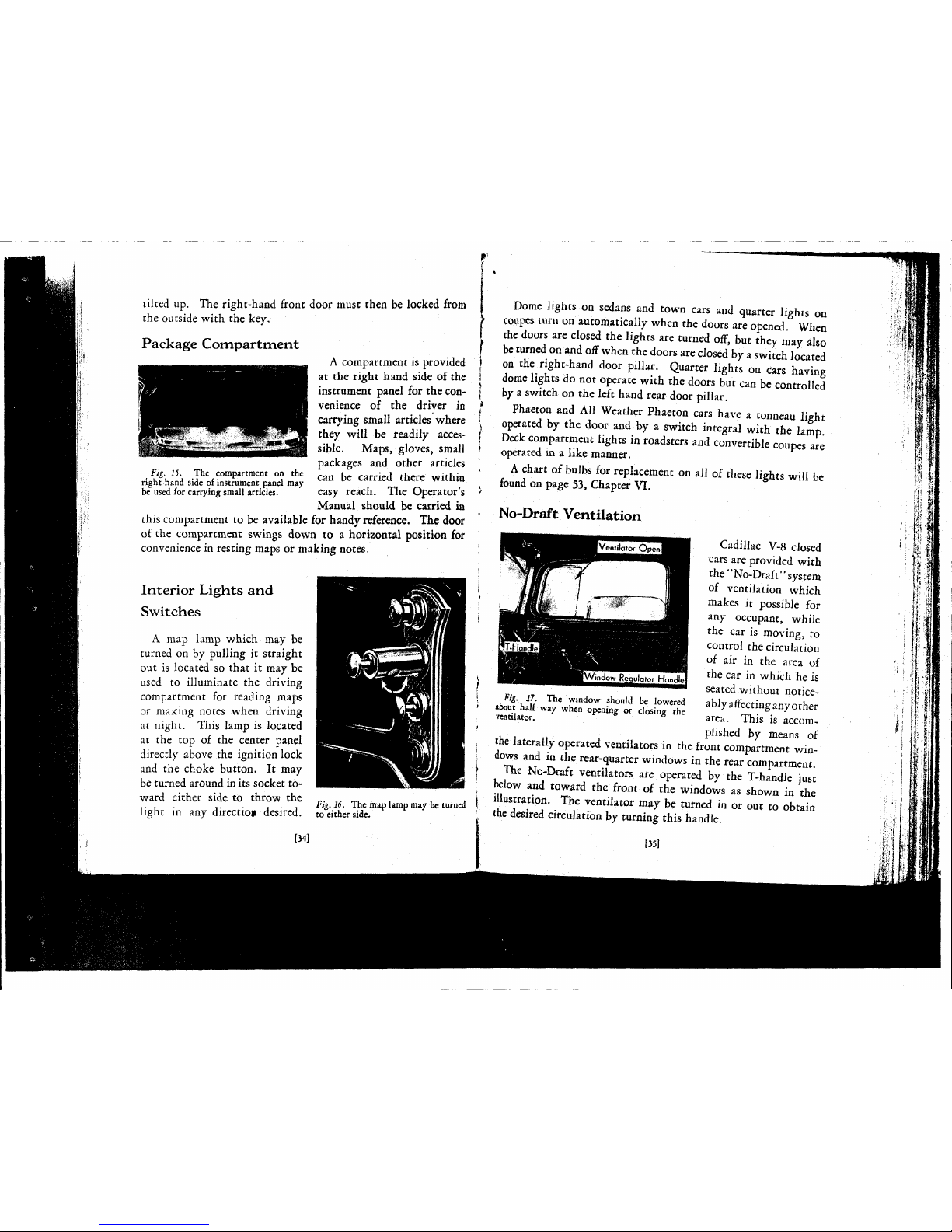
Fig.
15. The compartment on the
right-hand
side
of instrument panel may
be used for carrying small articles.
tilted up. The right-hand front door must then be locked from
the
outside
with the key.
Package
Compartment
A
compartment is provided
at the right hand
side
of the
instrument panel for the convenience
of the driver in
carrying
small articles where
they
will be readily
acces-
sible.
Maps,
gloves,
small
packages and other articles
can be carried there within
easy
reach. The Operator's
Manual
should be carried in
this
compartment to be available for handy reference. The door
of
the compartment
swings
down to a horizontal position for
convenience in resting maps or making
notes.
Interior
Lights
and
Switches
A
map lamp which may be
turned
on by pulling it straight
out is located so that it may be
used to illuminate the driving
compartment for reading maps
or
making
notes
when driving
at night. This lamp is located
at the top of the center panel
directly above the ignition lock
and
the choke button. It may
be turned
around
in
its
socket
to-
ward
either
side
to throw the
light in any direction desired.
[341
Fig.
16. The inap lamp may be turned
to either side.
Dome lights on
sedans
and town cars and quarter lights on
coupes
turn on automatically when the doors are opened. When
the doors are closed the lights are turned off, but
they
may
also
be
turned
on and off when the doors
are
closed by a switch located
on the right-hand door
pillar.
Quarter lights on
Cars
having
dome lights do not operate with the doors but can be controlled
by a switch on the
left
hand rear door
pillar.
Phaeton and All Weather Phaeton cars have a tonneau light
operated by the door and by a switch integral with the lamp.
Deck
compartment lights in roadsters and convertible
coupes
are
operated in a like manner.
A
chart of bulbs for replacement on all of
these
lights will be
found
on
page
53,
Chapter
VI.
No-Draft Ventilation
#1..77
The window should be lowered
TOrilator
Whe" 0pCnin« or ciosing the
Cadillac
V-8 closed
cars are provided with
the
"No-Draft"
system
of
ventilation which
makes it possible for
any occupant, while
the car is moving, to
control
the circulation
of
air in the area of
the car in which he is
seated
without noticeably affecting any other
area.
This is accom-
plished by
means
of
jjnantu
py
means
o
the laterally operated ventilators in the front compartment win-
dows
and in the
rear-quarter
windows in the rear compartment.
The
No-Draft ventilators are operated by the T-handle just
below
and toward the front of the windows as shown in the
illustration.
The ventilator may be turned in or out to obtain
the desired circulation by turning
this
handle.
[351
Page 31
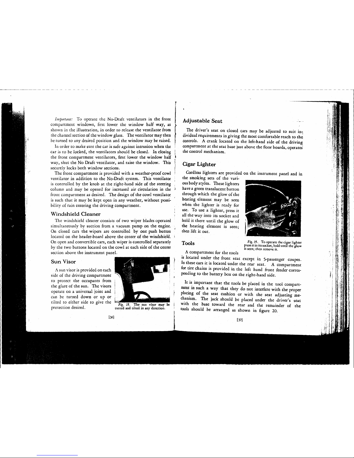
Important
To operate the No-Draft ventilators in the front
compartment windows, first lower the window half way, as
shown in the illustration, in order to
release
the ventilator from
the channel section of the window
glass.
The
ventilator
may
then
be turned to any desired position and the window may be raised.
In
order to make sure the car is
safe
against intrusion when the
car
is to be locked, the ventilators should be closed. In closing
the front compartment ventilators, first lower the window half
way, shut the No Draft ventilator, and raise the window.
This
securely locks both window
sections.
The
front compartment is provided with a weather-proof cowl
ventilator in addition to the No-Draft system.
This
ventilator
is controlled by the knob at the right-hand
side
of the steering
column
and may be opened for increased air circulation in the
front
compartment as desired. The design of the cowl ventilator
is such that it may be kept open in any weather, without possibility
of
rain
entering the driving compartment.
Windshield
Cleaner
The
windshield cleaner
consists
of two wiper blades operated
simultaneously by suction from a vacuum pump on the engine.
On
closed cars the wipers are controlled by one push button
located on the header-board above the center of the windshield.
On
open and convertible cars, each wiper is controlled separately
by
the two buttons located on the cowl at each
side
of the center
section above the instrument panel.
Sun
Visor
A
sun visor is
provided
on each
side
of the driving compartment
to protect the occupants from
the glare of the sun. The visors
operate on a universal joint and
can
be turned down or up or
tilted to either
side
to
give
the .. „ _ . .
.
° Fig. 18. The sun visor may be
protection desired. turned
and
tilted in
any
direction.
136]
Adjustable
Seat
The
driver's
seat
on closed cars may be adjusted to suit in-;
dividual
requirements in giving the
most
comfortable
reach
to thei
controls. A crank located on the left-hand
side
of the driving
compartment at the
seat
base
just above the
floor
boards,
operates
the control mechanism.
Cigar
Lighter
Cordless
lighters are provided on the instrument panel and in
the smoking
sets
of the
vari-
ous
body
styles.
These lighters
have a green translucent button
through
which the glow of the
heating
element
may be
seen
when the lighter is ready for
use. To use a lighter,
press
it
all
the way into its
socket
and
hold
it there until the glow of
the heating
element
is
seen;
then lift it out.
_ . Fig.
19.
To operate the cigar lighter
1
OOlS
press it
in
its socket,
hold
until
the glow
is
seen;
then remove it.
A
compartment for the
tools
is located under the front
seat
except
in 5-passenger coupes.
In
these
cars it is located under the rear
seat.
A compartment
for
tire chains is provided in the
left
hand front fender corres-
ponding
to the battery box on the right-hand side.
It is important that the
tools
be placed in the tool compart-
ment in such a way that
they
do not interfere with the proper
placing
of the
seat
cushion or with the
seat
adjusting me-
chanism.
The jack should be placed under the driver's
seat
with the
base
toward the rear and the remainder of the
tools
should be arranged as shown in
figure
20.
137]
Page 32

t
Page 33

li|y8ryul^ll.fflil^^
.
Fig.
20. Arrangement of the
tools
in
the tool compartment.
Tires
Tool
equipment provided
with the car is as follows:
Hammer
Large
Screw
Driver
Small
Screw
Driver
Pliers
Spark
Plug Wrench
Crescent Adjustable
Wrench
Jack
Handle
Jack
Hub
Cap and Wheel
Mounting
Wrench
Tool
Bag
Operator's
Manual
For
normal driving the front and rear tires should be inflated
to a pressure of 40 lbs.
Important—On
cars driven at high
speeds,
the front tires should be inflated to 45 lbs.
The
tires should be checked at
least
weekly and brought up to
the recommended pressure if
necessary.
The pressure should
never be permitted to drop
more than five pounds. If
this
is done, tire wear will
be kept at a minimum.
Use
of
Jack
When
a tire is flat, the
axle
is not always far enough above
the ground to permit placing
the jack directly under the
axle. In such
cases
the jack
should be placed under the
spring,
as shown in Fig. 21,
as near the
axle
as possible.
Fig.
21. The jack should be placed
under the spring as near the
axle
as
possible.
1381
Spare
Wheel
Carrier
To
remove a spare wheel
from
the carrier either on
the rear of the car or in
the fenders, first remove
the hub cap; then unlock
the lock and take it out,
using the key as a handle.
It may be
necessary
to hold
the lock while turning the
key. Unscrew the clamping
nut
underneath
the
lock.
On
cars with the wheel carrier
in
the rear, the wheel may
then be lifted off. On cars
Fig.
2) The spare
wheels
on cars
with ienderwell carriers may be removed after loosening the brace rod
clamping
screw.
F
'i'P'
r
Tbe
clam
P">g
nut
may be
reached after unlocking and removing
the lock.
5
with fenderwell carriers, however, the clamping knob on the
brace rod must first be
loosened
by turning to the
left
until the
wheel may be cleared from the
brace rod and lifted off.
To
reinstall a spare wheel on
the rear carrier, mount it on the
carrier,
reinstall the clamping
nut, snap the lock back into
place and place the dust shield
in
position. On fenderwell
carriers,
place the wheel in the
well, screw the clamping knob
on the brace
rod
down until the
clamping
screw can be pushed
into position and install the
clamping
nut. Reinstall the
lock
and the
hub
cap, then screw
the brace rod clamping knob
139]
Page 34

r
down
until
the wheel is held solidly in place.
Changing
Wheels
If
a fully inflated spare tire is always
carried,
it is only
neces-
sary,
in
case
of
tire
trouble, to remove the wheel with the flat tire
and
install the spare wheel in its place. Illustrated directions for
performing
this work are given in
figure
24, page 41. jj
In
case
tire trouble develops when no spare is available, the tire j
can
be easily removed
from
the drop-center rim for
repair.
In- (
structions for removing and installing tires on the
wheels
are j
given on
pages
50 and 51,
Chapter
VI.
/¾.
24a.
Set the
hand
brake
lever
to prevent the car
from
rolling
and
jack
up the axle. Remove the hub
cap
with the wrench in the tool kit
Arrows
on the hub cap indicate the
direction
in which it turns off and
on.
I
,F'&-
24i
-
Loosen the nuts around
the wheel hub by turning them in a
counter clockwise direction with
!
*e wrench. Remove the nuts and
i
pull
the wheel off of the hub
Fig.
24c.
To remount the wheel,
set it up on the hub and start the
nuts by
hand;
then tighten the nuts
with the wrench, but not in rota-
tion.
After
tightening one nut,
tighten the nut directly opposite
until
all have been securely drawn
up.
Install the hub cap, using the
hub cap
wrench,
and lower the jack.
NOTE:
In drawing up the nuts to
the last
turn,
a slight alternate in-
crease
and
decrease in resistance may
te noticed which simply indicates
that the locking feature is taking
effect.
After
all the nuts have been
tightened, they should again be
tried
to make sure that none has
been resting on a high point with-
out being sufficiently tight.
1¾.
24.
Changing
Wheels.
[40]
141]
Page 35

»
t.
Page 36

CHAPTER
VI
GENERAL CARE
N
o
ATTEMPT
has been made to include
in
this
manual
directions
for
making adjustments and repairs to the car. Most
Cadillac
owners prefer to depend on authorized
Cadillac-La
Salle
service
stations
for such work as
these
stations
can invariably
perform
the work more conveniently and economically.
Every
owner should, however, know how to perform the few
simple operations of
general
care described in this chapter. These
operations are not difficult
enough to
necessitate a visit
to the service station,
although this work also
can
be done in the service
station if desired.
Storage
Battery
The
Delco Storage battery
is
carried
in a compartment
in
the right-hand front
fender. The battery may be
reached after removing the
four
screws
and taking off
the
cover
shown in
figure
25.
The
battery is filled with an acid solution
from
which the
water slowly evaporates and fresh distilled water must be added
to each of the three
cells
at regular intervals to
bring
the level up
to the bottom of the filling tubes. Distilled water should be
added
at
least
every 1000 miles and, in warm weather, every 500
miles or at
least
every two
weeks.
Hydrant
water or water that
has been in contact with metallic surfaces is not satisfactory.
Fig.
25. The cover of the battery com-
partment is held by four
screws.
142]
After
adding water to the storage battery in freezing weather,
the
car
should immediately be
run
far enough to thoroughly mix
the water with the
acid
solution. If the
car
is
parked
immediately
after water is added, the water is likely to stay on top of the acid
solution and may freeze, thus causing
extensive
damage to the
battery.
No
attempt should be made to add acid or any so-called "re-
juvenator solution" to the battery.
Adding
anything other than
distilled
water
will
materially shorten the life of the battery.
The
specific gravity of the acid solution changes as the battery
is
charged
and
discharged.
The
state
of
charge
of the battery can
thus be determined by measuring the specific gravity of the
solution with a hydrometer. As the battery is charged, the
specific gravity of the solution increases, reaching 1.270 to 1.285
when the battery is fully
charged.
A fully discharged battery has
a
specific gravity of 1.150 to
1.165-
An
accurate
test
cannot be made immediately after adding
distilled
water. The hydrometer reading should be taken before
water is added, or, if the solution is so low that it cannot be
reached,
distilled water should be added to
bring
the solution up
to the proper level and the car run for several hours
until
the
solution is properly mixed before the
test
is made.
Generator
Charging
Rate
Current
is supplied to the battery
from
a generator driven by
the engine and the generator charging rate must be high enough
to
keep the battery
charged.
Under
normal
operating conditions,
if a
hydrometer
test
shows
the battery is low the charging rate
should
be checked and adjusted at a service station. If the
test
shows
the battery is extremely low, the battery should be re-
charged
from
an
outside source before continuing to drive the
car.
Winter
driving
places greater strains on the battery than
summer
driving
and the generator charging rate should be adjusted to take care of the increased demands. If the maximum
charging
rate is not sufficient to take care of this extra load,
(431
Page 37

r
*
Page 38

arrangements
should be made to have the battery charged from
an outside source periodically to insure dependable operation }
throughout the winter months.
Spark
Plugs
The spark plugs provide the spark
which
ignites the gasoline
mixture in the cylinders, and smooth and economical engine
performance depend largely upon their efficiency. The accumula- |
tion
of carbon and improper gap setting are generally the
cause
\
of
inefficient spark plug operation. Their efficiency can be in- '
creased in such
cases
by cleaning out the carbon and by resetting •
the gap.
To
clean carbon from the insulator,
fill
the lower
part
of the
plug
with
alcohol,
liquid
metal
polish
or equal
parts
of ammonia >
and water and
allow
it to stand for a few seconds. Rub the carbon
from
the insulator
with
a wire covered
with
one thickness of
cloth;
then wipe it clean and dry before replacing the spark plug
in
the engine.
Whenever spark plugs are reinstalled in the engine, the
firing
j
points should be
tested
to make
sure
they are properly spaced, j
The gap should be .025 to .028 inches, measured
with
a feeler ;
gauge.
All
adjustments of the gap should be made by moving the )
side wire only. j
Cooling
System
The radiator
filler
cap is located on the
right hand side of the
engine under the hood.
The capacity of the
cooling
system is 6½
gallons
when
filled
to
a
point about 1½
inches below the top
of
the
filler
neck. When
Fit. 26. The
radiator
filler
cap is on the
right
hano
side
of the car
under
the
hood.
[44]
the car is delivered to the owner, the
cooling
system contains, in
addition
to the water and whatever anti-freeze is used, a small
amount of a special inhibitor
which
gives the
cooling
liquid
a
milky
appearance. This inhibitor has particular
advantages
in
reducing
foaming and retarding the formation of rust and scale,
thus
helping to keep the
cooling
system clean so
that
it
will
better
perform its
cooling
action. It is not necessary to add the
inhibitor
each time water or anti-freeze is added. Whenever the
cooling
system is drained and
refilled,
however, it is recommended
that
}4 °f a p
lnt:
(about 6 ounces) of a suitable inhibitor be added.
Consult
your Distributors or Dealer concerning the proper in-
hibitor
to use.
In
freezing weather a suitable anti-freeze solution, such as
those
described on
page
26, should be used. The inhibitor, although
it
has no anti-freezing qualities in itself,
will
blend satisfactorily
with
any approved anti-freeze but should not be used
with
any
solution
already containing a
similar
inhibitor (see
page
28).
Allowances
must, of course, be made when testing the
cooling
solution
for the effect the inhibitor has on its specific gravity.
Before
the
start
of
cold
weather, the
cooling
system should be
cleaned and thoroughly inspected to make
sure
all connections
are tight. If the inhibitor is
used, this cleaning
will
suffice
for
the entire year; otherwise
it
is advisable to clean it
thoroughly every 6000 miles,
using
the reverse
flow
method
which
is standard at all Autho-
rized
Cadillac-La
Salle Service
Stations.
If
this is not possible, a satis-
factory
cleaning, although not
as effective as the reverse
flow-
method, may be obtained by using the
following
procedure:
Run
the engine
until
the opening of the radiator
shutters
indicates
that
the engine is warm; then stop the engine and open
145]
Fig. 27. The
cooling
system
may be
drained
by
opening
the one
valve.
Page 39

t
*
Page 40

the
drain
valve on the
right-hand
side
of the
engine
at the water
inlet elbow and a little to the rear of the generator as shown *
in
figure 27.
After
the
liquid
has drained off,
refill
the cooling
system
with warm water,
run
the
engine
for a few moments, and
drain
the system. Repeat this operation
until
the water is clean |
when it is drained.
In
cases
where the
accumulation
of
rust
and
scale
is so great that t
this method
does
not clean the
system
sufficiently, the flushing [
operation
should again be repeated after one or two handfuls of
sal
soda have been added.
Care
must be taken, of
course,
that the ,
cooling
system
is thoroughly flushed after this operation to clean
out all traces of the sal soda, and that none of the solution is ;
allowed to reach the car finish. >
Gasoline
System
A
gasoline
filter
is
provided
at
the bottom of the fuel
pump
on
the front left-hand
side
of the
engine. Any accumulation of
water or sediment should be
cleaned out when it can be
seen
in
the
glass
bowl.
The
bowl may
be
removed
by
unscrewing the thumb nut on
the underside of the bowl and
swinging the yoke to one side.
The
screen strainer at the top
of
the bowl usually
comes
off
with the bowl but if it
does
not, it may be removed by pulling it straight down.
Any
dirt
on the strainer should be washed off with gasoline
and
the bowl should be wiped clean. The bowl should then
be reinstalled with the screen on top.
Make
sure the bowl
seats
properly against the
cork
gasket
at tl..e top of the filter,
Fig. IS. The gasoline filter should
be
removed
and cleaned whenever water
or
sediment appears in the bowl.
swing the yoke into place
and
tighten
the
thumb
nut
The
strainer on the carburetor
where the gasoline
enters
should
also
be cleaned periodically. It may be
removed
by disconnecting the feed
pipe,
removing the two cap
screws
Fig.
it.
The
strainer
h the
above
the
inlet
connection shown in
carburetor
may
be
removed
with figure 29. Both the strainer and the
&%%*1Z££?&
sedimentchambershouldbecleanedin
two
screws
shown.
the
same
manner
as
the gasoline filter.
Carburetor
Air
Cleaner
The
carburetor intake silencer
serves
also
as an air cleaner.
This
cleaner is designed to catch any dust or lint in the air
before it is drawn into the
carburetor.
It is automatic in opera-
tion
and requires no attention other than periodic cleaning.
The
mileage at which the air cleaner requires attention depends
entirely upon the conditions under which the car is operated.
For
normal
driving
in
cities
and on
hard
surfaced roads, cleaning
once
every
6000
miles is
sufficient.
Under
extreme
conditions, however, such
as continuous
driving
on
dusty roads or in localities
where there is considerable
dust in the
air,
cleaning
may
be required as frequently as
every
2000
miles.
The
air cleaner may be
lifted
out, as shown in
figure 30, after the cover
of
the intake silencer has
been removed. The cover 30.
The
cover to the
air
cleaner
and
, , •41,,
silencer should not be washed under any
ot the silencer is held by circumstances.
Air
G
over
146]
[47]
Page 41

*
*
Page 42
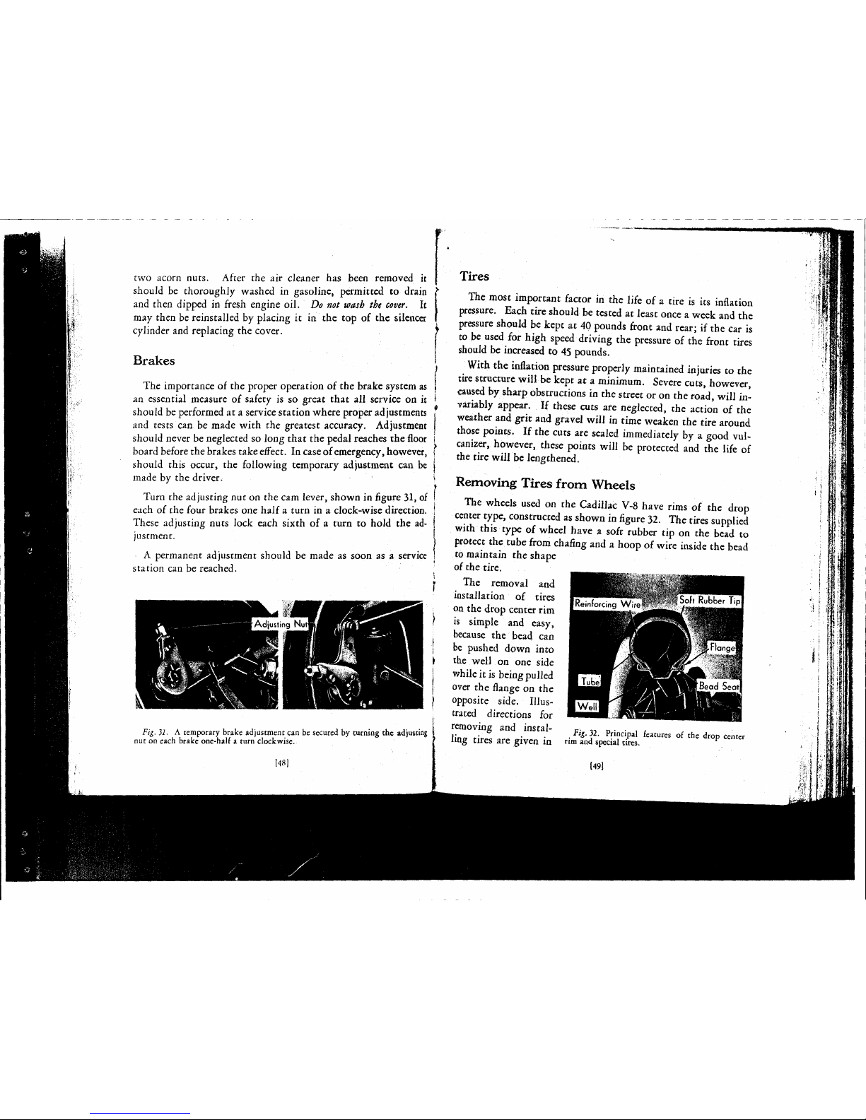
two acorn nuts.
After
the air
cleaner
has
been removed
it
should
be
thoroughly washed
in
gasoline, permitted
to
drain
and
then dipped
in
fresh engine oil. Do
not
wash
the
cover.
It
may
then be reinstalled by placing
it in the top of the
silencer
cylinder
and replacing
the
cover.
Brakes
The
importance
of
the proper operation
of
the brake system as
an
essential measure
of
safety
is so
great that
all
service
on it
should
be
performed
at a service station where
proper
adjustments
and
tests can be
made with
the
greatest
accuracy. Adjustment
should
never be neglected
so
long that
the
pedal reaches the floor
board
before the
brakes
take
effect.
In
case
of
emergency, however,
should
this occur,
the
following temporary adjustment
can be
made
by the
driver.
Turn
the
adjusting nut on the cam lever, shown in figure 31, of
each
of
the four brakes
one
half a turn
in a
clock-wise direction.
These adjusting nuts lock each sixth
of a
turn
to
hold
the
ad-
justment.
A
permanent adjustment should
be
made
as
soon
as a
service
station can be reached.
Fig.
3i. A
temporary brake adjustment can
be
secured
by
turning
the
adjusting
nut on each brake one-half a turn
clockwise.
148]
Tires
The
most important factor
in the
life
of
a tire
is its
inflation
pressure.
Each
tire should be
tested
at
least
once a
week
and
the
pressure should
be
kept
at
40 pounds front and
rear;
if
the car
is
to
be
used
for
high speed
driving
the
pressure
of the
front tires
should
be
increased
to
45 pounds.
With
the
inflation pressure
properly
maintained injuries
to the
tire
structure
will
be
kept
at a minimum.
Severe cuts, however,
caused by
sharp
obstructions in the
street
or on the
road,
will
in-
variably
appear.
If
these
cuts
are
neglected,
the
action
of the
weather and grit and gravel
will
in
time weaken
the
tire
around
those
points.
If the
cuts are sealed immediately
by a
good vul-
canizer,
however,
these
points
will
be
protected and
the
life
of
the tire
will
be lengthened.
Removing Tires from
Wheels
The
wheels
used
on the
Cadillac
V-8 have rims
of the
drop
center type, constructed as shown in figure 32.
The
tires supplied
with this type
of
wheel have a soft
rubber
tip on the
bead
to
protect
the
tube
from
chafing and a hoop
of
wire inside the bead
to maintain
the
shape
of
the tire.
The
removal
and
installation
of
tires
on
the
drop center
rim
is simple
and
easy,
because
the
bead
can
be pushed down into
the well
on one
side
while it is
being
pulled
over
the
flange
on the
opposite side. Illustrated
directions
for
removing
and
instal-
Bg 32 principal
knuKS
o( the
drop ccntcr
ling
tires are given
in
"m and
special tires.
(491
Page 43

f
•
Page 44

Fig.
33a. Deflate the tube com.
pletely and remove the rim nut on
the valve stem. Loosen both beads
from
the bead
seats,
using a tire tool
if
necessary. Stand on the tire,
opposite the valve stem, with the
feet
about 15 in. apart, to force the
bead into the
rim
well.
Fig.
34a.
Coat
both beads of the
tire
with
vegetable
oil
soft
soap
before reinstalling the tire. Inflate
the tube
until
barely rounded out
and
insert in the tire with the stem
at the tire balancing
mark.
Place
the tire on the rim, guiding the
valve through the hole, and apply
the rim nut loosely. Push the
bottom bead down into the well at
the valve and force the remaining
portion
of the bead over the rim
flange, using a tire tool if necessary.
Fig.
33b. Insert two tire tools,
about 8 in. apart,
between
the bead
and
the rim Uange near the valve.
Leaving
one tool in position, pry
short lengths of the bead over the
flange with the other
until
the entire
bead has been removed.
Fig.
34b.
Force the top bead over
the
rim
flange and into the well at
the point opposite the valve.
Kneeling
on this side of the tire to
hold
it in the well, pry short
lengths of the remaining portion of
die bead, working around the rim
until
the entire bead is in place.
Always
keep as much of the top
bead in the well as possible while
prying
the
remainder
of the bead.
Fig.
33c.
Remove the inner tube
before attempting to remove the
second bead. Raise the wheel to
an
upright
position, insert a tire tool
between
the second bead and the
rim
flange at the top side of the
wheel and pry the wheel out of the
tire.
This
operation
will
be sim-
plified
if the
soft
tip of the bead is
first coated with
vegetable
oil
soft
soap.
Fig.
34c.
Remove the
rim
nut and
push
the valve stem back into the
casing as far as possible without
letting go of the stem to make
certain
that the tube is not pinched
under
the bead; then reapply the
cim
nut.
With
the wheel flat on
the floor, inflate the tire slowly,
making
sure that both
sides
of the
tire
are
centered on the rim.
Fig
33. Removing
Tires
Fig.
34. Reinstalling
Tires
[5U
Page 45

***
1»
Page 46
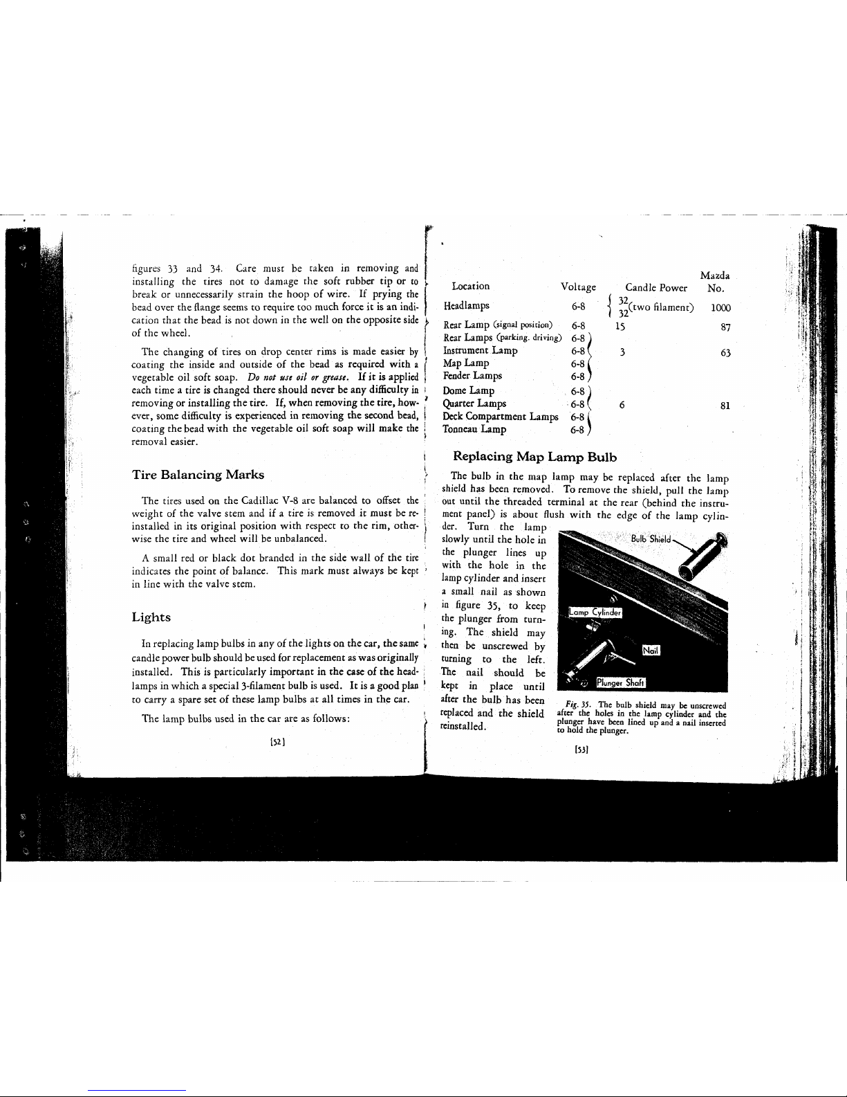
figures
33
and 34.
Care
must
be
taken
in
removing and
installing
the
tires
not to
damage
the
soft
rubber tip or
to
break
or unnecessarily strain the hoop of wire.
If
prying the
bead over the flange
seems
to require too much force it is an
indi-
cation that the bead is not down in the well on the opposite
side
^
of
the wheel.
The
changing
of
tires on drop center rims
is
made easier by
coating the inside and outside
of
the bead
as
required with a
!
vegetable
oil
soft
soap. Do
not use
oil
or
grease.
If it is applied
(
each time a tire is changed there should never be any difficulty
in
!
removing
or installing the tire. If, when removing the tire, how-
'
ever,
some
difficulty is experienced in removing the second bead,
\
coating the bead with the
vegetable
oil
soft
soap
will make the
1
removal
easier.
Tire Balancing Marks
The
tires used on the
Cadillac
V-8 are balanced
to
offset
the
weight
of the valve
stem
and if a tire
is
removed
it
must be re-
installed in its original position with respect
to
the
rim,
other-
wise
the tire and wheel will be unbalanced.
A
small red or black dot branded in the
side
wall
of
the tire
indicates the point of balance.
This
mark
must always be kept
in
line with the valve stem.
Lights
In
replacing lamp bulbs in any of the lights on the
car,
the
same
\
candle power
bulb
should be used
for
replacement
as
was
originally
installed.
This
is
particularly
important in the
case
of the head-
;
lamps
in
which a special 3-filament bulb is used. It is a good
plan
1
to
carry
a spare set of
these
lamp bulbs at all
times
in the car.
The
lamp bulbs used in the car are as follows:
152]
Location
\
Headlamps
Rear
Lamp
(signal position)
Rear
Lamps
(parking, driving)
Instrument
Lamp
Map
Lamp
Fender
Lamps
Dome
Lamp
Quarter
Lamps
Deck
Compartment
Lamps
Tonneau
Lamp
Candle
Power
Mazda
No.
32
32
15
Xtwo
filament)
1000
87
63
81
Replacing
Map
Lamp
Bulb
The
bulb in the map lamp may be replaced after
the
lamp
shield has been removed. To remove the shield,
pull
the lamp
out until the threaded terminal
at
the rear (behind the instru-
ment panel)
is
about flush with
the
edge
of
the lamp
cylin-
der. Turn
the
lamp
slowly until the hole in
the plunger lines
up
with
the
hole
in the
lamp
cylinder
and
insert
a small
nail
as
shown
in
figure
35, to
keep
the plunger from
turn-
ing.
The
shield
may
then
be
unscrewed
by
turning
to the
left.
The
nail
should
be
kept
in
place until
after the bulb has been
fig_ 35. The
buib
shield
may
be
unscrewed
replaced
and the shield af
ter
the
nolcs
in
£.he
lam
P
cylinder »nd the
.
plunger have been lined up and a
nail
inserted
reinstalled.
to hold the plunger.
153)
Page 47

4
«
•A'
Page 48

Aiming
the
Headlamps
The
headlamps used on the
Cadillac
V-8 are of the Depress-
Beam
fixed-focus type and the only adjustment ever necessary is
the aiming of the beam. The aim of the lamps should be
tested
periodically
according to the following procedure,
except
when
state
or local regulations apply, and aimed if necessary. In
cases
of
state
or local regulations, this procedure should be modified to
meet
the legal requirements.
A
light colored vertical surface, such as a blank wall or the
garage door, on which the light beams can be projected from the
car
at a distance of about
25
feet,
should be used to make the
test.
Draw
in the lines shown in
figure
36 according to the dimensions
indicated.
The vertical center line may be located by sighting
through
the center of the rear window of the car across the
radiator
cap to the wall.
Center
Line
Fig.
36.
Light
pattern of the left-hand headlamp with the cartwenty-five
feet
from
the vertical surface and the light switch in the
"Driving"
position. The
location of the beam should be determined in relation to the lines drawn in at the
dimensions indicated.
One
lamp at a time should be
tested
with the
lens
in place and
with the light switch lever in the
driving
position. If the aim is
correct,
the light beam will be patterned and located as shown in
figure 36 for the left-hand lamp and as in
figure
37 for the right-
hand
lamp.
If
the pattern of either lamp is not located as shown in the
diagrams,
the lamp out of alignment should be re-aimed.
This
[54]
Fig.
37.
Light
pattern of the right-hand headlamp projected under the
same
conditions as the left-hand headlamp.
may be done by loosening the acorn nut (figure 38) and turning
the lamp
sidewise
and up or down until the pattern is correctly
located. It is important of course that the
flutes
on the
lens
be straight up and down at all
times. The lamp should then
be held in place while the
adjusting nut is securely tightened.
Any
replacement of parts
of
the lamps should be with
identical
parts of the
same
make. The manufacturer's
name is clearly marked on
the lens, on the reflector and
on
the lamp housing. Two-
filament bulbs of
32-32
candle
power are originally supplied
with the car and should be
Storing
the Car
If
the car is to be stored for any length of time it is important
that a few precautions be taken to protect it from deterioration.
Blocking
up the
car
to take the
weight
off of the tires and placing
[551
Fig.
3S. The headlamps may be
turned
in any direction necessary for
aiming
after loosening the clamping
nut at the
base
of the lamp.
specified for replacement.
Page 49

*
0
4*
f
*
4
Page 50

a
cover over the entire body
will
protect the tires and
finish.
The
engine
and
the storage battery, however,
require
special attention.
Oil
should be injected into the cylinders while the engine
is
warm.
This
may be done by
pouring
two or three tablespoonsful
of
engine oil into the spark plug
holes
after the engine has been
run
long enough to
warm
it up.
Cranking
the engine a few times
after this
is
done
will
distribute the oil evenly over the pistons
and
cylinder walls. The cooling system should then be drained.
The
battery should be fully charged and the solution should be
at the proper level. If possible, arrangements should be made to
have
the
battery charged
from
an
outside source every
two
months
during
the storage period.
Body
The
body
of a Cadillac
car
is
deserving of care and attention
the same as the most intricate working parts of the chassis.
In
recognition of this fact,
Author-
ized
Cadillac-La
Salle Service
Stations displaying the
Complete
Service Sign, shown in
figure
39,
at the bottom of the authorized
service sign have
equipped
them-
selves
to
service the body with
as much expert
skill
and care as
the chassis. The simple atten-
»
tions described below, however,
Fig.
19.
Authorized
Cadillac-La
are frequently
performed
by the
Salle Service Stations displaying this
owner
or
under his immediate
sign are equipped to render complete
. .
body
service.
Supervision.
Care
of the
Finish
Keeping
the lacquer
finish
of the car new and lustrous requires
only
a thorough wiping with a
soft
dry
cloth every few days and
[56]
an
occasional polishing with a recognized lacquer polish.
With
this care, the car
will
need to be washed only when considerable
mud
or dust has accumulated.
Washing
of the
car
can be accomplished simply and easily with
plenty
of
clean
cold
water, a soft
wool sponge
and a
clean chamois.
Soap
and
hot water
are
not only unnecessary but
undesirable.
The
dust or mud should be flushed off with a
gentle
stream of water
from a hose
without a nozzle, using the sponge merely to loosen
the
dirt.
After
all the
dirt
has been removed in this way,
the
sponge should be squeezed
dry and
used to
pick
up the water
from
the crevices. Thoroughly wet the chamois and
squeeze
it
dry,
then
rub
the
finish
with it
until
all of the water has been removed.
Care
of the Top
The
top may be kept clean by an occasional wiping to remove
the dust.
This
is all the
care
required
to keep the top clean
unless
grease
spots, stains or
dirt
film
occur.
In
these
cases
washing
with a mild,
neutral soap
may
be
resorted
to. Gasoline, naphtha,
kerosine and fabric cleaners should never
be
used since such
preparations
can easily
dull
the
finish and damage
the
fabric.
Soap and water is not
harmful
and
is
fully as effective.
Cleaning
Upholstery
Regular
monthly cleaning
of
the car interior with a vacuum
cleaner and a whisk broom
will
keep the upholstery in the
best
of
condition
and
will
prevent
excessive
wear.
The
whisk broom
should
be used
to
loosen the
dirt
and grit, which
causes
more
rapid
wear than use, while the vacuum cleaner should be used
to
lift
out the loosened
dirt.
Spots on
the
upholstery may be cleaned with any good dry
cleaner used
sparingly.
When
the cleaner has thoroughly evapo-
rated,
fold a piece
of
cheese
cloth
four
or
five times, dampen it, and
place it over the spotted surface; then run a hot
iron
over surface
just long enough to raise a good steam. Plush fabrics can be re-
stored to their
original
appearance by
rubbing
lightly against the
nap
with a
brush
after the fabric has been steamed in this way.
[57]
Page 51

i
i
i
Page 52

Door
Hardware
The
lubrication of the body hardware on the car is fully
as essential as the lubrication of
chassis
parts if it is to work
smoothly and silently. Directions for the lubrication of door
locks,
hinges
and striker
plates
every 1000 miles are included
on
the lubrication chart. These directions should be followed
as faithfully as the rest of the chart.
Body
Adjustments
Preventive service on the body at regular intervals will keep
the appearance of the car at its
best
and will eliminate more
extensive
repairs at a later date.
This
service should include
body bolts, tie-down bolts, door adjustments and the operation
of
window regulators.
Authorized
Cadillac-La
Salle service
stations
include the body
as well as
chassis
in the regular monthly or 1000 mile inspection
and
quote flat rate prices for necessary body service. The
necessary work may be authorized by the owner at the time he has
chassis
adjustments made and the car lubricated.
[58]
CHAPTER
VII
SPECIFICATIONS
AND
LICENSE DATA
Type
of
engine
8 cyl. V-type
Diameter of
cylinder
bore 3¾ in.
Length
of stroke 4rt in.
Piston displacement 353 cu. in.
Horsepower (N. A. C. C. rating)
36.45
Engine
number See below
Capacity
of gasoline tank 30 gals.
Capacity
of
engine
lubricating
system
8 qts.
Capacity
of cooling
system
6½ gals.
Capacity
of transmission 2¼ qts.
Capacity
of
rear
axle 3 qts.
Wheelbase
130-136
in.
Tires
7.00 x 17
Spark
plug setting
025-.028
in.
Contact
point setting
018-.024
in.
.
(
22-24
amps, cold
Generator
charging rate, maximum •}
1^1(,½^.
hot
Engine
and
Unit
Assembly
Numbers
Each
Cadillac
car, when shipped, carries an
engine
number
which
is
also
a serial number.
This
is the number to be used in
filling out
license
and insurance applications and in general
reference of the car. The
engine
number is stamped on the right
hand
side
of the crankcase near the water inlet.
The
various units, such as the transmission, steering gear, etc.,
also
carry
unit assembly numbers. These are located as described
[59]
Page 53

*
t
f
t
Page 54

below. It is important in ordering parts to give, not only the
engine
number of the car, but
also
the unit assembly number of •
the unit to which the part
belongs.
Transmission
number—on
the upper
edge
of the flange by which the }
transmission is bolted to the crankcase near the left-hand dowel.
Steering
gear
number—on
the steering gear housing
next
to the
grease
plug.
Generator
number—on
the right-hand
side
of the generator. 1
Starting
motor
number—on
the right-hand
side
of the starting
motor, just
below
the switch. '
Front
axle
number—-on
the front surface of the
axle
I-beam near
the right-hand spindle
;
Rear
axle
number—on
right-hand
side
of the
axle
housing to the
right
of the cover plate.
Chassis
(Jrame)
number—on
the flange of the first channel cross- j
member,
next
to the
left
front
engine
support.
Job
and
body
numbers—on
the right-hand
side
of the cowl under the |
hood.
|
INDEX
A
Accelerator
20
Accelerator,
use in cold weather 31
Adding
water to battery 42
Adjustable
scats
37
Air
cleaner
47
Alcohol
for anti-freeze 26
Ammeter
19
Anti-freeze
solutions 26
Authorized
service stations 5
B
Balancing
marks
on tires 52
Battery
29, 42
Battery,
preparing
for storage 55
Body,
Care
of 56
Brake
adjustment 48
c
Cadillac
service 3
Carbon
monoxide poisoning 25
Carburetor
air cleaner 47
Carburetor
flooded 22
Carburetor,
to
prime
31
Card,
identification 4
Changing
engine oil 17
Changing
tires 49
Charging
rate 43
Charges
for service 7
Chart,
lubrication
10
Chassis
lubricant
14
Choke
control
21
Cigar
lighters 37
Coasting
25
Cold
weather
lubrication
29
Cold
weather
operation
26
Compartment
for tools 37
Contract,
Service 8
Cooling
system 44
Crankcase
ventilating system.......16
D
Danger
from
carbon
monoxide 25
Door
Locks
33
Driving
Hints
24
DriverX
seat
adjustment 37
Driving
speed when new 5
[61
E
Effect
of alcohol on finish 27
Engine
fails to start 22
Engine
lubrication
15
Engine
number
59
Engine
oil 13
Engine
oil, changing 17
Engine,
preparing
for storage 55
Engine,
running
in garage 25
Equipment
32
F
Filter
for gasoline 46
Filler
for oil 16
Flat-rate
service charges 7
Flooded
carburetor
22
Flushing
cooling system 44
G
Gasoline
filter 46
Gasoline
gauge 18
Gasoline
system, cold weather 30
General
care 42
Glycerine
for anti-freeze 27
H
Headlamps
23, 54
Hood
Ports 20
I
Identification
card
4
Ignition
switch lock 33
Inflation
pressure 38, 49
Inspections 6
Instrument
Panel Package
Compart-
ment 34
K
Keys
32
1
Page 55

$
I
Page 56

V
L
License data 59
Lighting
switch
23
Locks
32
Locks
for
spare
tires
32, 39
Lubricants
12
Lubrication
11
Lubrication
Agreement 8
Lubrication,
chart 11
Lubrication,
cold
weather
29
Lubrication,
engine..
15
Lubrication
notice
11
Lubrication,
schedule
10
M
Map
Lamp 34, 53
N
No-Draft
ventilation. 35
o
Obligations of
owner
5
Oil
filter 16
Oil
level
16
Oil
pressure
18
Operation 18
P
Parts, uniform prices 6
Preventive
service
6
Priming
carburetor 31
R
Radiator
fillet
cap 44
Rear
axle
lubricant 14
Repair
parts 6
Replacing
engine
oil 17
Replacing filter cartridge 16
Ride Regulation 2J
S
Schedule
lubrication 10
Seat
adjustments
•. 37
Service contract 8
Copytight 1933 by
Cadillac
Motor
Car
Company
Service
charges
7
Service
stations
3
Spare tire carriers 39
Specifications
59
Specific gravity of battery 42
Standard Service Contract 8
Starting Hints 22
Starting the
engine
21
Starting the
engine
in cold
weather.
.30
Storage
battery 29, 42
Storing car 55
T
Throttle control 20, 30
Tire
balancing marks 52
Tire
carrier 39
Tire
pressure
38, 49
Tires,
changing 49
Tires,
preparing for
storage
55
Tools 37
Tourists,
service
to 4
Transmission lock 33
Transmission lubricant 14
u
Unit
assembly
numbers 60
Use of
accelerator
befote
engine
is
warm 31
V
Ventilator cowl 35
Ventilator, No-Draft 35
Visor
36
W
Water pump lubricant 15
Wheel bearing lubricant 14
Windshield
cleaner
36
Winter
lubrication 29
Winter
operation 26
Wheel carrier 39
355-cxi
200-1-33
Prinred
io 17. S.
A.
[62]
Page 57

¥
4
i
4
Page 58
Page 59

Changes
to be
made
in
"B"
series
Shop
Manual
Make
the
following
changes in your copy of the "B series Shop
Manual,
so
that
it
will
contain
the latest information. This information
does
not appear on the revised pages.
Page 11.
Differential
carrier assemblies (Note 1) are no longer serviced as a unit for V-8 and
V-12
"B"
and "C" series cars. See "Replacement and Adjustment of Rear
Axle
Ring
Gear and
Drive
Pinion,"
page
13A.
Page 19. The
sentence
"When ordering chassis
parts
affected by wheelbase, the
Body
Job Number
must be given the
same
as when ordering body parts" should be crossed out. This infor-
mation
is no longer necessary.
Page 32. The instruction "Lubricate control valve
with
light machine oil" should be changed to
read, "Lubricate
with
S. A. E. No. 10 oil or light machine oil of weight
similar
to shock
absorber
oil."
Page 46. In
Fig.
2, the dimension
Y%
in. indicating the distance the timing mark is ahead of the dead
center mark on 345-B and 355-B flywheels, should be changed to *nThe
dimensions 1 f-|- in. and 1Y in. for the 370-B and 452-B engines, respectively, applies only
to
these
models. On 370-C and 452-C engines the
ignition
timing mark is Yi in. ahead of
the center mark as measured on the circumference of the
flywheel.
Page 47. Opposite the subject
"Timing
mark IG/A ahead of center" the dimension for the
370-B
should be changed to 1¾".
Page 53. The piston clearances as given in Note 10 are no longer recommended. New
limits
have
been set up in production and are now recommended for
fitting
pistons in service for both
standard and oversize blocks. For V-8 and V-12 cars (with Electro-plated pistons), use a
.0025 in. feeler gauge,
with a pull
of 6 to 15 pounds
pull
on the spring scale.
With
V-16
cars (unplated pistons), use a .003 in.
gauge
with a pull
of 6 to 9 pounds on the scale.
Page 61. Opposite the subject
"Width
of rings—Lower compression (Two on
452-B),"
the dimension
Y" should be inserted in the 452-B column.
Page 79. The fourth paragraph in the second or right column should be changed to read as
follows:
"The
beam modification for Pennsylvania consists in rendering the 32 candle-power beam
in
the right headlamp inoperative by the use of a special switch lever at the top of the
steering wheel. In the remaining
states
the beam modification is obtained by disconnecting
the right head-lamp wire leading to the 32 candle-power filament in the lamp bulb. Owners
of
cars
thus
modified should be cautioned against any
attempt
to
restore
to use the filament
thus
eliminated."
NOTE—-A
special bulb with a filament
arrangement
of 21-32-21 candlcpower is available from the Factory Parts
Division,
under Part No. 883874, for use in the Super-Safe lighting system in Pennsylvania. When used in the Super-Safe
lamps,
these
bulbs provide a
City
Driving
Beam by lighting a 32 c.p. filament in each lamp in place of the 21 c.p.
filament normally used. This provides a very satisfactory driving light for either city or country
driving.
The
Country
Passing Beam utilizes both a 32 c.p. and a 21 c.p. filament in the left lamp and a 21 c.p. filament in the
right lamp. The
City
Passing Beam lights a 21 c.p. filament in each lamp. The Country
Driving
Beam is, of
course, not used. These
arrangements
all comply with the Pennsylvania law.
Pages 86 The caption above the top row of illustrations
"Clutch
Control
Cylinder"
should read
and 88.
"Clutch
Control
Valve."
Page 99. The yoke throw from neutral to applied position should be
Y—-3%"
instead of
3¾—-3V'.
Page 102. In Fig. 2, the yoke travel should be
Y—>n-
Page 107. The instructions presented in Note 1 for adjusting the front wheel bearings are now obsolete.
See latest recommendations given in Note 4 on
page
106B.
Page 109. Opposite the subject "Pressure in Pounds—Normal—Front and Rear" the Number 40
should
be changed to 35 for all car models.
The
following
item should also be included under Tires-Pressure in pounds. "The front
tires on all models should be inflated to 40 pounds for continuous high speed
driving."
The
rim diameter and tire size as given for the 452-B applies also to early 452-C cars.
Later
452-C cars are provided
with
17-in.
rims and 7.50 x
17-in.
tires the
same
as the
370-C.
August
1933
Page 60
CADILLAC - LA
SALLE
SHOP
MANUAL
CADILLAC
355-B-C, 370-B-C, 452-B^C
LA
SALLE
345-B^C
Service
Department
CADILLAC
MOTOR
CAR
COMPANY
DETROIT,
MICHIGAN
August
1933
Page 61
HPHIS
Shop
Manual
is a book of reference on the adjustment
and repair of
Cadillac
and La Salle motor cars. It is
intended for the use of service men who are already
familiar
with
automobile construction and repairing in general. It is
not a text book for
those
who have had no previous
Cadillac
shop experience and
does
not
present
instructions in elementary
form.
The style in
which
the information is presented is a distinct
departure
from the usual book of this sort. Straight reading
matter
has been eliminated as far as possible and the facts and
figures needed by service men are presented
briefly
in two
ways—by
illustrations and by tabulated specifications.
At
the beginning of each group is a
brief
description accom-
panied by service information in the form of notes.
Following
this is a specification table
giving
clearances, dimensions and
other facts important to service men. The
rest
of the informa-
tion
is in picture form.
Our
Service Department invites correspondence
with
Service
Managers and Shop Foremen on all
matters
discussed in the
Shop
Manual.
CADILLAC
MOTOR
CAR
COMPANY
Detroit,
Michigan
fa
Page 62
Introduction
Arrangement
of
Tables
'
| 'HE subjects covered in the specification tables are
listed
in alpha-
betical
order in the first
column.
Under
these
items
will
be found
important comments, cautions and references to illustrations and notes.
One
class of information in the specification tables consists of
limits
for
the clearance between
parts
subject to wear. The
limits
given
are
of
two kinds. The "New
limits
are those to be observed when
install-
ing
new parts. The
"Worn
limits
are those beyond
which
it is
inad-
visable
to continue to use the
worn
parts
if quietness of operation and
maximum
performance are to be expected. Some service, although not
the most satisfactory, can of course be obtained
from
parts
worn
beyond
these
limits.
Arrangement
of
Illustrations
The
illustrated
pages
are
laid
out to show as far as possible in picture
form
the repair operations, together
with
the differences and
similarities
of
the various car units.
Unless
otherwise
specified
all illustrations apply to both the
Cadillac
and
the
LaSalle.
Identification
Numbers
Each
Cadillac
and La
Salle
car when shipped carries an engine number
which
is also a car serial number.
This
is the number to be used in
filling
out. license and insurance applications and in general reference to
the car. On
Cadillac 3 55-B
and La
Saile
345-B
cars, this engine num-
ber is stamped on the crankcase near the water inlet on the right-hancl
side.
The
Cadillac
370-B
and
45
2-B
have the engine number stamped
on
the right-hand side of the crankcase on the generator drive chain
housing.
The
various units such as the engine, transmission, steering gear,
etc., also carry unit assembly numbers. These are located as described
in
the specification tables. It is important when ordering
parts
to
give,
not
only
the engine number of the car, hut also the unit assembly
number of the unit to
which
the part belongs.
Page 63

5
Contents
NOTE:
The information contained in
this
book is grouped
under
the
headings
shown below.
Front
Axle
Page
General Description 7
Service Information 7,9
Specifications 9
Plate 1. Front
Axle
Details 8
Plate 2. Front
Axle
Alignment, Camber and Caster 10
Rear
Axle
General Description 11
Service Information 11, 13A, 13B, 13D
Replacement and Adjustment of Rear
Axle
Ring
Gear and Drive Pinion 13A, 13B, 13D
Specifications 13
Plate 3. Rear
Axle
Details and Alignment 12
Plate 3A. Details of Rear
Axle
Gear Adjustment 13C
Body
General Description 15 21B
Service Information . . . . .. . 17 18 2IB 21D' 21F
Body
Type and Job Numbers for "B" Series Cars .' ' ' 19
Body
Type and Job Numbers for "C" Series Cars 21A
Body
Type and Job Numbers 19
Plate 4. Door Window Details and Windshield Adjustmsnt 14
Plate 5. Body Mounting and Door Details .. .. . ... 16
Plate 6. Location and Type of Moulding Fastenings—Fisher and Fleetwood Bodies. . . .... 20
Plate 7. Location and Type of Moulding Fastenings—Fleetwood Bodies ... 21
Plate 7A. Front Door Details—"C" Series Cars 21C
Plate 7B. Rear Door and Rear
Quarter
Window Details—"C" Series Cars.21E
Brakes
General Description 23, 27B
Service Information 23, 25, 27B
Specifications 25
Plate 8. Brake Connections and Adjustments 22
Plate 9. Brake Assister Adjustments, Cadillac 370-B and 452-B 24
Plate 10. Diagrams Showing Operation of Vacuum Brake Assister, Cadillac 370-B and 452-B 26
Plate 11. Brake Details and Adjustments 27
Plate 11A. Diagrams Showing Operations of Vacuum Brake Assister—Cadillac 355-C—LaSalle 345-C 27A
Plate 11B. Brake Assister Adjustments—Cadillac 3 5
5-C—LaSalle
345-C 27B
Clutch
General Description 29 31
Service Information 3135
Specifications ' ,
?
Plate 12. Clutch Details '. '28
Plate 13. Adjustment of Clutch Pedal Control and Driven Disc Details.. 30
Plate 14. Power Clutch Control Adjustments 32
Plate 15. Accelerator Pedal Adjustment and Power Cylinder and Control Valve Details33
Plate 16. Diagram Showing Operation of Power Clutch Control 34
August
1933
Page 64

6
Contents
Cooling
System
ge
General Description - . . 37
Service Information 37
Specifications 39
Plate 17.
Cooling
System Details ' .. 35
Plate 18. Water Pump Details and Drive Adjustments - 38
Electrical
System
General Description 41, 43, 5OA
Service Information 43, 50A
Specifications 45, 47
Plate 19.
Generator
and Starting Motor Details 40
Plate 20. Circuit Control Box and Horn Adjustments 42
Plate 21. Ignition Distributor 44
Plate 22. Ignition Timing 46
Plate 23. LaSalle 345-B
Wiring
Diagram 48
Plate 24. Cadillac 355-B, 370-B and 452-B
Wiring
Diagram 49
Plate 25. Ignition
Wiring
Diagrams 50
PlateUA.
Ignition Timing—Cadillac 355-C and LaSalle 345-C Using Type 661-P Distributor JOB
Engine
General Description 51
Service Information 51, 53, 55, 67A, b7B, 68
Specifications 57, 59, 61, 63
Engine
Speeds
55
Table of Cylinder
Heads
and
Gaskets
67
A
Plate 26. Sectional Views of Cadillac 355-B Engine,
Typical
of LaSalle 345-B 52
Plate 27. Bottom
View
of Engine and Valve Details, Cadillac 355-B, LaSalle 345-B 54
Plate 28.
Generator
and Water Pump
Drive,
Cadillac 355-B, LaSalle 345-B 56
Plate 29. Cross-sectional
View
of Cadillac 370-B,
Typical
of Cadillac 452-B
except
number
of Cylinders 58
Plate 30. Bottom
View
of Engine and Cylinder Details, Cadillac 370-B and 452-B 60
Plate 31. Valve Details, Cadillac 370-B and 452-B 62
Plate 32. Front End
Drive,
Cadillac 370-B and 452B 64
Plate 33. Piston and Connecting Rod, Vacuum Pump and Engine Mounting 65
Plate 34.
Oiling
System, Cadillac 355-B, LaSalle 345-B 66
Plate 35.
Oiling
System, Cadillac 452-B,
Typical
of 370-B 67
Exhaust
System
General Description 69
Service Information -. 69
Plate 36. Exhaust System Details 69A
Fenders
Plate 36A. Front Fender Tie Rods—"C" Series Cars 69B
Frame
General Description 71
Specifications 71
Plate 37. Frame Alignment 70
Gasoline
System
General Description 73, 75
Service Information 75, 77
Specifications 77
Plate 38. Carburetor Details and Adjustment and
Intake
Muffler,
Cadillac 355-B, LaSalle 345-B 72
Plate 39. Carburetor Details and Adjustment Cadillac 370-B and 452-B 74
Plate 40. Fuel Pump and Carburetor Air Cleaner 76
August
1933
Page 65

Contents
___
Lighting
System
Pa
s
e
General Description 79, 81
Service Information °J
Specifications 7a
Plate 41. Lamp Details 78
Plate 42.
SUPER-SAFE
Lamp Bulb and Focusing Charts 80
Lubrication
Service Information S3
Specifications 83
Engine Oil Recommendations
8
^
Changes
for "B" Series Lubrication Charts for "C" Series Cars 85
Plate 43. Lubrication Schedule and Record Card, Cadillac 355-B,
Typical
of LaSalle 345-B 84
Plate 44. Lubrication Chart, Cadillac 355-B,
Typical
of LaSalle 345-B 86
Plate 45. Lubrication Schedule and Record Card, Cadillac 370-B,
Typical
of 452-B 87
Plate 46. Lubrication Chart, Cadillac 370-B,
Typical
of 452-B 88
Springs
and
Shock
Absorbers
General Description 89, 92A
Service Information 89, 92A
Specifications 91
Chart Showing Interchangeability of
"B"
and "C"
Series
Shock Absorbers 92B
Plate 47. Modulator and Spring Shackles 90
Plate 48. Shock Absorbers and Control 92
Plate 48A. Shock Absorbers—"C" Series Cars 92A
Steering
Gear
93
General Description gy
Service Information • g-j 95
Specifications '0.4
Plate 49. Steering Gear and Connections
%
Plate 50. Steering Gear Adjustments
Transmission
General Description 97
Service Information 97 j
q^a
Specifications 99 101
Speedometer
Pinion Chart ! ioi! 103
Plate 51. Sectional
View
of Transmission,
Typical
of all Models \ 98
Plate 52. Transmission Synchronizing Mechanism
[.........
100
Plate 53. Transmission Adjustments 102
Plate 54. Removal and Disassembly of Transmission 104
Plate 55. Disassembly of Transmission ' 1C5
Plate 56. Dissassembly of Transmission 106
Plate 56A. Adjustment of Gear Shift Lever 106A
Wheels,
Rims
and
Tires
107
General Description \0bB 107
Service Information ' jq
Q
Specifications ma
Plate 57. Wheel and Rim Details (V°
Plate 58. Removing Tire from Drop Center Rim V
Plate 59. Installing Tire on Drop Center Rim
August
1933
Page 66

Supplementary Introduction
'
I 'HE
information
presented in the
Cadillac-LaSalle
"B" series Shop
Manual
will
in nearly all instances apply to the "C" series cars
.;
There are, however, certain
cases
where the construction, adjustment
or
specification
of a "C" series unit differs
from
the corresponding "B"
series unit.
In
order to make the "B" Shop
Manual
fully
applicable to the "C"
series cars as
well
as the "B" series, supplementary
pages
have been
issued
for insertion in the "B" manuals.
While
these
pages
are pre-
sented
primarily
to cover the differences in the "C" series cars, they
also
contain new
information
on the
"B"
series as
well
as the
"A"
series
cars.
The
supplementary
pages
can be
identified
by the
date
"August
1933"
printed in the
lower
margin close to the
binding
edge.
Page 67

7
FRONT
AXLE
FILE
General
Description - .
bit
A-w
The front axles used on
Cadillac
and
LaSalle
cars are of the reverse
Elliot
type. They are ol
the
same
general construction, but differ slightly
in
minor details. The
345-B,
355-B and 370-B
axles are identical but differ from the 452-B axle
in
dimensions and the drop of the I-beam. The
452-B
steering arms are also slightly longer
because
of the larger brakes and for this reason
the cross rod is shorter than on the other models
The steering knuckles pivot on adjustable
ball
bearings at both the top and the bottom. The
lower
bearing
takes
the combined
thrust
and
radial
load and the upper one
takes
radial load
only.
The knuckle bolts and bearings are entirely
outside of the brake dust shields. This construe-
of
"tease
tion
prevents any possibility
knuckles
getting on the brakes
The front wheels are also carried on
ball
hear-
ings
which
are adjustable.
The steering cross-rod joints are of the
ball
and
socket type. The joints are fitted to a definite
tightness
because
friction
at this point has an
important effect in steadying the (ront wheels.
That is, the point of contact between the pivot
and the
seats,
together
with
the heavy springs
for
holding the
seats
against the pivot, makes it
possible to control the
friction
at the joint so as
to absorb road shock without causing hard steering.
The service operations and adjustments of the
front axle are the
same
on all cars.
Service
Information
1. Caster
Angle
The caster angle on all models is 2½ to 3½°. Wedge plates
are to be used when necessary between the front springs and
the spring
seats
on the I-beam to give this
caster.
Test the caster
with
a suitable
gauge
with
the car on a
level
floor
to determine the correct wedge plate to use. Place
the thick
edge
of the plate toward the
rear.
The
following
wedge plates may be secured from the factory
Parts
Division
:
1°
Wedge Plate—Part No. 873787
1½°
Wedge Plate—Part No. 876813
2.
Straightening Bent Parts
Because of their location, the
parts
of the front axle are
more subject to damage by accident than any other
part
of
the chassis. Front: axle service, therefore, involves the inspection
of
parts
for alignment and possible straightening.
Heat-treated
parts
should not be straightened if they are
sprung out of alignment more than 5°. To straighten such
parts
while
cold
is
likely
to result in strains and sometimes in
cracks not
visible
to the naked eye. Straightening
with
heat
destroys the effect of previous
heat
treatment
and may result
either in overheating, making the steel soft and weak, or
in
underhe;iring
which
will
make it brittle and easily broken.
Parts
which
are not
heat-treated
may be straightened
cold
if
not sprung out of alignment more than 10°.
Welding
of
pans
subjected to severe strain should'never
bo permitted. A welded
part
is never as strong as the
original,
unbroken metal and the
heat
required for the welding process
changes the structure of the metal around the
weld,
making
it
coarse and/weak". '
3.
SteejrjiW|*Ci^sSTh}d
Joint Adjustment
The tightness of the cross-rod joint should be such
that
a
pull
of 10 to 18 pounds at the end of a 6-in. wrench is necessary
to turn the pivot in the socket. This
test
is made by disconnecting the pivot from the steering arm, reinstalling the retaining
nut on the pivot and turning the pivot
with
a wrench as
shown
in Fig. 3, Plate 1. The pivot should be
well
lubricated
when
making this
test.
If
the spring tension is insufficient, it can be adjusted by
installing
thin shims under the take-up spring.
4. Stop Screw Adjustment
The left-hand stop screw should be adjusted to keep the
inner
wall
of the tire % to % in. away from the steering con-
necting rod.
Prior
to steering gear units I
1-125(5
on the 345-B and 12-1245
on
the 355-B and
370-B, a greater
clearance may be necessary
in
order to prevent the sector from bottoming against the
housing
in the steering gear when turning to the left. 1 he
left-hand stop screw should be adjusted so
that
it. comes into
play
just before the sector bottoms in the housing, making
sure
that
the clearance is not less than
that
specified above.
The right-hand stop screw should be adjusted to give a
clearance of not less than 2¾' in. between the
lire
and the
frame oh' all cars.
Page 68

8
FRONT
AXLE
Broke Cable
Cam
lever,.
Wheel
Hub
Wheel
Bearings
Adjusting
Plug
/
rake ievor
Fig.
2
Rear
side
of
dust shield
showing
brake
connections
Steering Knuckle
^Steering Knuckle
Arm
I beam
Check
knvckle
bearing adfusf-
ment
by
lifting wheel
up and
down with
bar.
Tighten
adjust-
ing plug only enough
to
eliminate
ptay.
Adjust toe-m
by
turning cross
rod.
^Install thin shims under spring
if
spring tension
is
insufficient.
Fig-
J
Sectional
View
of
Front
Wheel,
Hub and
Steering
Knuckle.
Typical
of all
models.
Fig.
3
/ Testing tightness
of
steering
cross
rod joint
with
spring
scale.
A pull
of at
loast
!0 pounds
should
be
neccs
sary
to to:n
pivot
1
10
18 lb:
Plate 1.
Front Axle
Details
Page 69

9
FRONT
AXLE—Service
Information—Specifications
5.
Steering
Knuckle Bearing
Adjustment
The adjustment
of the
steering knuckle bearings
can be
checked
by
lifting
the
wheel
up
and down
with a bar.
In
case
of
looseness,
the
adjusting plug should
be
tightened.
Use a
wrench
with a handle
12 to 15 in.
long
and
tighten
the ad-
justing
plug
as
tight
as
possible
by
hand.
Do not
loosen
the
adjustment except
to
eliminate binding
in the
steering.
6.
Front
Wheel
Bearing
Adjustment
The procedure
to
follow
in
adjusting
the
front wheel
bear-
ings
is
first
to
make
sure
that
the
wheel
is
all
the
way
on the
spindle.
Then tighten
the
adjusting
nut as
tight
as
possible
by
hand using a wrench
with a handle
12 to 15
in.
long,
after
which
back
off the nut one
third turn
or two
flats.
If the
locking
device cannot
be
placed
in
position without changing
the adjustment, tighten instead
of
loosen
the
adjusting
nut
until
it
can
be
secured
with
the
locking
device.
It is
preferable
to have
the
adjustment
on the
tight side
rather
than
the
loose
side provided
it is not
necessary
to
tighten
the nut
more than
one
half
the
distance
to the
next cotter pin slot.
It
is
also a good plan
to
turn
the
wheels toward
the
right
side when adjusting
the
left wheel bearings
and
toward
the
left
side when adjusting
the
right wheel bearings
to
assure
full
release
of the
brakes.
CAUTION:
When adjusting
the
front wheel bearings, care
should
be
taken
not to
mistake play
in the
knuckle bolts
for
play
in the
wheel bearings.
Specifications
LaSalle
Cadillac
345-B
355-B
370-B
452-B
H-l"
1½°
M-i°
1½
0
5i-l°
1½°
1½°
7¾"
99½°
8^-8½°
99¾°
8M-8H°
7¾°
99M°
8^-8½°
7¾
0
99¼°
2H-3
H°
90°
2^-3½°
90°
2^-3½°
90°
2^-3½°
90°
.½°
l
A°
m"
8¾"
8¾"
w
200-225
I
j
2 a if
1 32
|
200-225
I
i
w
j
200-225
i
2.1»
32
200-225
i
.010"
10-18 lbs.
.010"
10-18 lbs.
i
i
.010"
1
10-18 lbs.
r
.010"
10-18 lbs.
'
Vs-%"
!
I
1 H-Vb"
1 3
If
T
ti~
1 6
j
16-16
i
1 JSJ'
16-16
l
_3_"
16"
16
59¾"
59¾"
59¾"
59¾"
Subject
and
Remarks
Camber
of
front wheel (angle
with
vertical), Fig. 1 Plate 2—
With
car
weight
on
wheels
With
car
weight off wheels
Angle
between steering knuckle bolt and vertical—
With
car
weight
on
wheels
With
car
weight off wheels
Angle
between steering knuckle bolt
and
wheel spindle.
Caster angle (See Note
1)
Angle
between spring
scats
and
vertical plane
of
I-beam
I-beam twist—allowable variation between
ends
(misalign-
ment between steering knuckle bolts) (Sec Note 2),..
..
Road
clearance under front axle
Measure
with
new lires
inflated
to
40-45
lbs. and no load
in car.
Steering cross-rod
end
spring—
Free length
Compression
in
pounds when compressed
to in
Springs
must
not
show
any set
when
compressed
with
coils
touching.
Steering cross-rod joint—•
Adjustment (See Note
3),
Fig.
1,
Plate
1
Pivot
balls
out of
round—worn
limit,
not
over
Pull
necessary
to
turn pivot in socket (See
Fig.
3,
Plate
1)
Steering knuckle bearing adjustment (See Note
5)
Stop screw adjustment (clearance between tire
and
nearest
point
of
possible interference) (See Note
4)
Toe-in
of
front wheels, Fig.
7,
Plate
2
Tread
Type
Unit
number location
All
models—On
top of
R. H. spring pad.
Wheel
bearing adjustment (See Note
6)
Reverse
Elliot
Reverse
Elliot ! Reverse
Elliot
Reverse
Elliot
August
1933
Page 70

10
FRONT
AXLE
(Camber
a J
Angle) A^
Cliff
Wheel
Spindle
Cenfer
/ine of
knuckle
pin
Fig.
3
Fronf
Wheel Caster
Check
with
caster gauge
on
level
floor.
All
wheels must
be
same
dis-
tance
off
floor.
Caster angle
can be
changed
by
inserting wedge plate
between
I-beam
and
spring
with
thick edge toward
rear.
Fig.
1
Elements
of
Fronf Wheel Camber.
Check camber
with
camber gauge
on
level
floor.
Adjust height
of
hubs
by al-
tering tire pressure.
Fig.
2
Fig.
4
Checking
steering knuckle
pin
angle Checking angle
of
steering
knuckle
pin
with
spring seat
Fig.
6
R. H.
Steering Knuckle
Arm.
L. H.
Steering Knuckle
Arm.
Fig.
7
Front Wheel Alignment
(toe-in)
Check
with
front wheel aligning
gauge.
Adjust by
turning steering cross
rod.
Front
Axle
Specifications
345-B 355-B
(Except
156 in.
W.B.)
370-B
(Except
156 in. W.B.)
355-B,
370-B
(156 in.
W.B.)
452-B
A-B-C
See "Camber"
under
"Specifications,"
Page
9 for
these
dimensions
D-E
"D"
should
be }| in.
less
than
"E"
F
23^-3½°
23^-3½°
|
2^-3½°
2J_-3J_°
G-H
"G"
should equal "H"
I
6,¾"
6*»
6A"
6¾"
J
2 9'/
32 32
w
K
W
2 9
If
~f
w
w w
L
1H'
ltt*
\w
2ts"
2
A"
M
7¼"
7½"
7½"
OS/'
N
2 9 it
3 2
29
"
3 2
2 9
"
"32
w/
1½"
O
11"
j
a
JJ-."
1
1
"
"i
*>
1 5"
32
15"
3 2
P-Q
"P"
should
be
y6—1¾
in.
less
than
"Q"
measured
against
tire side
wall 8 in.
above
floor.
Plate 2.
Front
Axle
Alignment,
Camber
and
Caster
Aukusi
1933
Page 71

11
REAR
AXLE
General
Description
Cadillac
and
LaSalle
rear
axles are of the
three-
quarter
floating type. They are similar in con-
struction but differ somewhat in dimensions and
in
gear
ratios.
The construction of the
rear
axle for the 345-B,
3 5 5-B and 370-B
cars
is identical with the excep-
tion
of the
gear
ratio. The 370-B ratios are
slightly
lower than the corresponding ratios for
the 345-B and 355-B.
The 452-B
rear
axle is of the
same
design as
that
of the other models but the
gear
ratios are
different and the axle is somewhat larger to
accommodate the heavier car.
The
rear
axle housing on all models is of the
banjo type and carries not only the driving
parts
but also the
rear
brake mechanism. It is designed
for
underslung springs.
The differential is of the two-pinion type with
bronze washers to
take
the
thrust
of the side
gears
and the differential pinions.
The differential is carried on tapered roller
bearings while
ball
bearings are used for the
driving
pinion.
The differential carrier is reinforced by a plate
installed
between the differential cover and the
axle housing and fitting over the cap bolts. This
reinforcement acids considerably to the
rigidity
of
the differential carrier.
The driving
thrust
of the
rear
axle is
trans-
mitted through the
torque
tube
to the
ball
and
socket joint which is attached to the
rear
end of
the transmission.
The axle
shafts
are keyed to the driving
hubs
to which the wheels are bolted. This
arrangement
allows
the use of a single annular type
ball
bear-
ing
in each
rear
wheel to
take
the load. This con-
struction is typical of the
three-quarter
floating
principle.
Baffle
plates
are used in the axle housing to keep
excessive lubricant from getting into the wheel
bearings. Two baffles are used for each shaft,
one
near
each end. There is also a threaded
bushing in the outer end of each housing
tube
which
functions as an oil return.
The service operations and
adjustments
of the
rear
axle are the
same
on all models.
Service
Information
1. Differential Carrier Installation
Before
differential carrier assemblies are shipped by the
Parts
Division,
all lubricant is washed out of the bearings-
It is important, therefore, to lubricate the pinion shaft
bearings before the assembly is installed, or they are liable to be
damaged before the differential lubricant works its way up
to them.
Place
assembly on end with
gears
up, and pour
about
a
pint of differential lubricant on the pinion. Leave the assem-
bly
in this position
until
the lubricant has run down through
the back bearing and has thoroughly lubricated the front
bearing. The assembly is now ready for installation.
After
installation, the differential
case
should, of course, be
filled
to the proper
level.
2.
Gear Adjustment
•
The pinion and ring
gear
are properly adjusted at the
factory, and this
adjustment
should not be changed. II
adjustments
or replacements are ever necessary, the entire
differential
carrier assembly should be replaced and the old
one,
together
with its original shims,
sent
to the Factory
Parts
Division
for exchange.
Use
a Puller
(Tool
No. I-IM 1094(14) when removing the
propeller shaft from the pinion shaft. Do not use a hammer
in
removing the shaft or the pinion shaft may be damaged.
Page 72

12
REAR
AXLE
Differential
Pinion Shaft
Ring
Gear
Differentia/
Pinions
Propeller
Shaft
Rivet
"A"
and "B"
when housing « right side
up
should
C"
should equal
"D"
when either fare
of
housing
is
down.
equal
"A"
and "8"
wficn
housing
is
up'Sith: down
fig. 2
Rear
Axle Housing on V
Blocks
for Testing
.Rivet
Rollei
Bearing
Tig. 3
Sectional Ww of
Jerque
/ubc one/ Propeller
Shrift
Exten-
sion for 156 ./) W.B. Gi/>-Cod;7.
!
uc 3 55 8 one/ 370 8
Plate
3.
Rear
Axle
Details
and
Alignment
Page 73

13
REAR
AXLE—Specifications
LaSalle
Cadillac
Subject
and
Remarks
345-B
355-B
370-B
452-B
Use front wheel alignment gauge
to
check alignment
of
rear wheels
A"
A'
A"
A"
33A"
33A"
33
A"
33A"
35¾"
35H"
35¾"
35M"
A"
i
it
A"
A"
Gear
adjustment
or
replacement
(See
Note
2)
Gear ratios—
4.36
: 1
4.60
: 1
4.36
: 1
4.60
: 1
4.60
: 1
4.80
: 1
4.31
: 1
4.64
: 1
See Lubrication Section
Propeller
shaft
length (overall)—
55 W
61¾"
55 W
61¾"
55 W
61¾"
59A"
65
A"
54A"
59A"
65
A"
60A" 60A"
60*' 60*'
.010"
.010"
.010"
.010"
Propeller
shaft,
side
clearance
between
splines
and hub of
universal joint
.001-.005"
.006"
.001-.005"
.006"
.001-.005"
.006"
.001-.005
.006"
To
be
measured with tires inflated
to 40 lbs. and no
load
in
car.
7%"
8½"
8H"
61"
61"
61"
|
61"
%
Fit.
%F!t.
%
Fit.
H Fit.
All
models—-Rear
surface
of
housing
at
lower
R. H.
side
_
Page 74
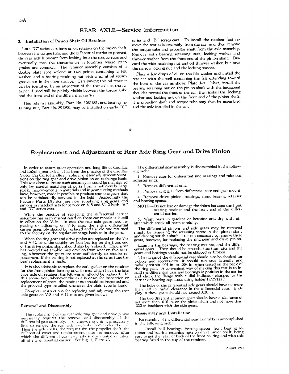
13A
REAR
AXLE—Service
Information
3.
Installation
of Pinion
Shaft
Oil
Retainer
Late
"C" series cars have an oil retainer on the
pinion
shaft
between the torque
tube
and the differential carrier to prevent
the rear axle lubricant
frcm
leaking into the torque
tube
and
eventually into the transmission in localities where
steep
grades
are common. The retainer assembly consists of a
double plate spot welded at two points containing a felt
washer, and a bearing retaining nut
with
a spiral oil return
groove cut in the outer surface. Cars having this oil retainer
can
be identified by an inspection of the rear axle as the re-
tainer if used
will
be
plainly
visible
between the torque
tube
and the front end of the differential carrier.
This
retainer assembly, Part No. 1081881, and bearing re-
taining
nut, Part No. 891890, may be installed on early "C"
series and "B" series cars. To
install
the retainer first re-
move the rear axle assembly from the car, and then remove
the torque
tube
and propellor shaft from the axle assembly.
Remove
both bearing retaining nuts,
locking
washer and
thrower washer from the front end of the
pinion
shaft.
Dis-
card
the wide retaining nut and oil thrower washer, but save
the narrow
locking
nut and the
locking
washer.
Place
a few drops of oil on the felt washer and
install
the
retainer
with
the
well
containing the felt extending toward
the front of the car as shown Plate 3-A. Next,
install
the
bearing retaining nut on the
pinion
shaft
with
the hexagonal
shoulder toward the front of the car, then
install
the
locking
washer and
locking
nut on the front end of the
pinion
shaft.
The propellor shaft and torque
tube
may then be assembled
and the axle installed in the car.
Replacement
and
Adjustment
of Rear Axle Ring Gear and Drive Pinion
In
order to
assure
quiet operation and long
life
of
Cadillac
and
LaSalle
rear axles, it has been the practice of the
Cadillac
Motor
Car Co. to handle
all
replacement and adjustment opera-
tions on the ring gear and drive
pinion
on an exchange basis.
This
was done to insure such accuracy as
could
be maintained
only
by careful matching of.
parts
from a sufficiently large
stock. Improvements in materials and in gear cutting methods
have, however, made it possible to produce rear axle
gears
that
can
be satisfactorily serviced in the
field.
Accordingly
the
Factory
Parts
Division
are now supplying ring
gears
and
pinions
in matched
sets
for service on V-8 and V-12 both "B"
and "C" series cars.
While
the practice of replacing the differential carrier
assembly has been discontinued on
these
car models it is
still
in
effect on the V-16. In
case
the rear axle
gears
need re-
placing
or adjusting on V-16 cars, the entire differential
carrier assembly should be replaced and the old one returned
to the factory on the regular exchange basis as in the
past.
When
the ring gear and drive
pinion
are replaced on the V-8
and V-12 cars, the double-row
ball
bearing on the front end
of
the drive
pinion
shaft should also be replaced. Experience
has proved
that
trouble may develop from wear on this
bear-
ing,
whenever the
gears
are worn sufficiently to require re-
placement, if the bearing is not replaced at the
same
time the
gear replacement is made.
It is also advisable to replace the cork gasket on the retainer
for
the front
pinion
bearing and, in cars
which
have the late
type axle oil retainer, the felt washer should be replaced. In
this connection, whenever the axle is down for inspection or
replacement of gears, the retainer nut should be inspected and
the grooved type installed whenever the
plain
type is found.
Complete
instructions for replacing and adjusting the rear
axle
gears
on V-8 and V-12 cars are given below:
Removal
and
Disassembly
The replacement of the rear axle ring gear and drive
pinion
necessarily requires the removal and disassembly of the
differential
gear assembly. 1 o remove this unit, it is necessary
first
to remove the rear axle assembly from under the car.
Then
the axle shafts, the torque tube, the propeller shaft, the
differential
cover and reinforcement plate are removed, after
which
the differential gear assembly is dismounted or taken
off
of the differential carrier. See big. 1, Plate 5A.
The differential gear assembly is disassembled in the
follow-
ing
order:
1. Remove caps for differential side bearings and take out
adjuster rings.
2.
Remove differential unit.
3.
Remove ring gear from differential
case
and gear mount.
4. Remove drive
pinion,
bearings, front bearing retainer
and bearing spacer.
NOTE—Do
not lose or damage the shims between the front
bearing retainer and the front end of the differ-
ential
carrier.
5. Wash
parts
in gasoline or kerosine and dry
with
air
after
which
check all
parts
carefully.
The differential pinions and side
gears
may be removed
simply
by removing the retaining screw in the
pinion
shaft
and
driving
out this shaft. It is not necessary to remove
these
gears, however, for replacing the ring gear and drive
pinion.
Examine
the bearings, the bearing mounts, and the differ
ential
gears. They should be smooth, free from pits and the
gears
and bearings should not be chipped or broken.
The flange of the differential
case
should also be checked for
wobble
and eccentricity: it should run
true
laterally and
radially
within
.001 in. or .004 in. when
tested
on the back of
the ring
gear.
A convenient way of making this
test
is to in-
stall
the differential
case
and bearings in position in the carrier
and check the flange
with a dial
indicator clamped to the
carrier or bearing cap
studs
using holder
HM91220.
The hubs of the differential side
gears
should have no more
than .005 in. radial clearance in the differential case. Endplay
in
these
gears
should not exceed .020 in.
The two differential
pinion
gears
should have a clearance of
not more than .010 in. on the
pinion
shaft and not more than
.020 in backlash
with
the side gears.
Reassembly and Installation
Reassembly of the differential gear assembly is accomplished
in
the
following
order:
1. Install
ball
bearings, bearing spacer, front bearing re-
tainer and bearing retaining
nuts
on drive
pinion
shaft, being
sure
to get the retainer back of the front bearing and
with
this
bearing fitted in the cup of the retainer.
August
1933
Page 75
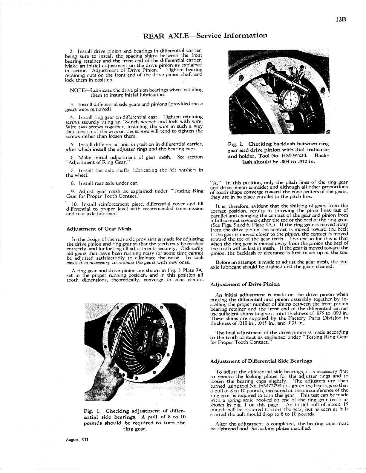
13B
REAR
AXLE—Service
Information
2.
Install drive
pinion
and bearings in differential carrier,
being
sure
to
install
the spacing shims between the front
bearing retainer and the front end of the differential carrier.
Make
an
initial
adjustment on the drive
pinion
as explained
in
section "Adjustment of
Drive
Pinion."
Tighten bearing
retaining
nuts
on the front end of the drive
pinion
shaft and
lock
them in position.
NOTE—Lubricate
the drive
pinion
bearings when installing
them to insure
initial
lubrication.
3.
Install differential side
gears
and pinions (provided
these
gears
were removed).
4. Install ring gear on differential case. Tighten retaining
screws securely using an 18-inch wrench and
lock
with
wire.
Wire
two screws
together,
installing the wire in such a way
that
tension of the wire on the screws
will
tend to tighten the
screws
rather
than loosen them.
5. Install differential unit in position in differential carrier,
after
which
install
the adjuster rings and the bearing caps.
6.
Make
initial
adjustment of gear mesh. See section
"Adjustment of
Ring
Gear."
7. Install the axle shafts, lubricating the felt washers in
the wheel.
8. Install rear axle under car.
9. Adjust gear mesh as explained under "Testing
Ring
Gear
for Proper Tooth Contact."
10.
Install reinforcement plate, differential cover and
fill
differential
to proper
level
with
recommended transmission
and rear axle lubricant.
Adjustment
of Gear Mesh
In
the design of the rear axle provision is made for adjusting
the drive
pinion
and ring gear so
that
the
teeth
may be meshed
correctly,
and for
locking
all adjustments securely.
Ordinarily
old
gears
that
have been running noisy for some time cannot
be adjusted satisfactorily to eliminate the noise. In such
cases
it is necessary to replace the
gears
with
new ones.
A
ring gear and drive
pinion
are shown in Fig. 3 Plate 3A,
set in the proper running position, and in this position all
tooth dimensions, theoretically, converge to cone
centers
Fig.
1. Checking
adjustment
of
differ-
ential
side
bearings.
A pull of 8 to 10
pounds
should
be required to turn the
ring
gear.
Fig.
2. Checking
backlash
between
ring
gear
and
drive
pinion
with
dial
indicator
and
holder,
Tool No.
HM-91220.
Back-
lash
should
be .004 to .012 in.
"A."
In this position, only the pitch lines of the ring gear
and drive
pinion
coincide; and although all other proportions
of
tooth
shape
converge toward the cone
centers
of the gears,
they are in no place parallel to the pitch
line.
It is, therefore, evident
that
the shifting of
gears
from the
correct position, results in throwing the pitch lines out of
parallel
and changing the contact of the gear and
pinion
from
a
full
contact toward either the toe or the heel of the ring
gear.
(Sec
Figs.
5 and 6, Plate 3A.) If the ring gear is moved away
from
the drive
pinion
the contact is moved toward the heel;
i
f the gear is moved closer to the
pinion,
the contact is moved
toward the toe of the gear
teeth.
The reason for this is
that
when
the ring gear is moved away from the
pinion
the heel of
the tooth
will
be last in mesh. I f the gear is moved toward the
pinion,
the backlash or clearance is first taken up at the toe.
Before
an
attempt
is made to adjust the gear mesh, the rear
axle
lubricant should be drained and the
gears
cleaned.
Adjustment
of Drive Pinion
An
initial
adjustment is made on the drive
pinion
when
putting the differential and
pinion
assembly
together
by in-
stalling
the proper number of shims between the front
pinion
bearing retainer and the front end of the differential carrier
use sufficient shims to give a total thickness of .075 to .090 in.
These shims are supplied by the Factory Parts
Division
in
thickness of .010 in., .015 in., and .035 in.
The
final
adjustment of the drive
pinion
is made according
to the tooth contact as explained under "Testing
Ring
Gear
for
Proper Tooth Contact. '
Adjustment
of
Differential
Side
Bearings
To
adjust the differential side bearings, it is necessary first
to remove the
locking
plates for the adjuster rings and to
loosen
the bearing caps
slightly.
The
adjusters
are then
turned, using tool No. hM72799 to tighten the bearings so
that
a
pull
of 8 to 10 pounds, measured at the circumference of the
ring
gear,
is required to turn this
gear.
This
test
can be made
with
a spring scale hooked on one of the ring gear
teeth
as
shown
in Tig. 1 on this page. An
initial
pull
of about 15
pounds
will
be required to
start
the
gear,
but as soon as it is
started the
pull
should drop to 8 to 10 pounds.
After
the adjustment is completed, the bearing caps must
be tightened and the
locking
plates installed.
August
1933
Page 76

13C
REAR
AXLE
Torque
Tube
Oil
Retainer
Cork
Gasket,
Bearing Retainer
Spacer
Differential Carrier
Propeller Shaft
Rivet
ved Retaining
Nui
ims
Drive Pinion Bearings
Drive Pinion
Differential
Case
and
Gear
Mounf
Differential
Side Gear
Axle
Housing^
IS
Locking
Plate
Differential
Pinion
Ring
Gear
Retaining
Screws
Fig. 1
Axle
Gear Assembly
Differential
Side Bearing
Adjuster Ring
MF^8*1^-^
Axle Shaft
Bearing
Cap
Shaft Retaining
Screw
Differential Pinion Shaft
Ring Gear
Backlash-
Fig. 2
Backlash between drive pinion
and
ring
gear
should
be .004
to .012 in.Check
with
dial
indi-
cator
Pitch Line
Face Contact - Ring Gear Tooth.
Correcf
by moving drive pinion
toward ring gear
Ring Gear
Pitch Lines
Ring
Gear
(b)
Reverse
(a)
Driving
Fig.
3-Correcf
Ring Gear Tooth Contact
(a) Driving
(b) Reverse
Pitch Lines
Fig. 5-Excessive Toe Contact — Ring Gear Tooth
To
correct contact increase backlash between gears(keeping
it under .012
in.) by
moving ring gear
away
from drive pinion
Flank
Contact -
Ring
Gear Tooth.
Correct by
moving drive pinion
away
from ring gear
Fig. 4
To
change profile contact
on
ring gear
teeth,
move pinion endwise
by
installing
shims
of
different thickness between
front pinion bearing retainer
and
front
end
of
differential carrier
(a) Driving
(bj Reverse
Fig. 6-Excessive Heel Contact — Ring Gear Tooth
To
correct contact decrease backlash between gears(keeping
it over
.004 in.) by
moving ring gear toward drive pinion
Plate
3A.
Details of
Rear
Axle
Gear
Adjustment
August
1933
Page 77
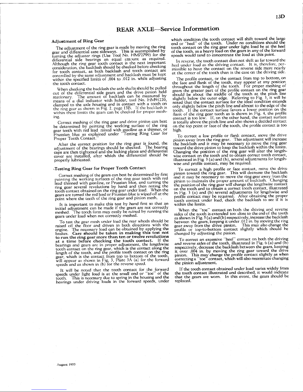
13D
REAR
AXLE—Service
Information
Adjustment
of Ring Gear
The
adjustment of the
ring
gear is made by
moving
the ring
gear and differential case sideways.
This
is accomplished by
turning
the adjuster rings (Use
Tool
No.
HM72799)
for the
differential
side bearings an equal amount as required.
Although
the
ring
gear tooth contact is the next important
consideration,
the backlash should be checked before checking
for
tooth contact, as both backlash and tooth contact are
controlled
by the same adjustment and backlash must be kept
within
the
specified
limits
of .004 to .012 in.
while
adjusting
the tooth contact.
When
checking the backlash the axle shafts should be
pulled
out of the differential side gears and the drive
pinion
held
stationary. The amount of backlash can be measured by
means of a
dial
indicator
with
holder,
tool
No.
HM91220,
clamped
to the axle housing and in contact
with
a tooth on
the
ring
gear as shown in
Fig.
2, page 13B. If the backlash is
within
these
limits
the gears can be checked for proper mesh-
ing.
Correct
meshing of the
ring
gear and drive
pinion
can best
be determined by painting the
working
surface of the
ring
gear teeth
with
red lead
mixed
with
gasoline as a thinner, or
Prussian
blue as explained under "Testing
Ring
Gear for
Proper
Tooth Contact."
After
the correct position for the
ring
gear is found, the
adjustment of the bearings should be checked. The bearing
caps are then tightened and the
locking
plates and differential
cover
are installed, after
which
the differential should be
properly
lubricated.
.Testing
Ring Gear for Proper Tooth Contact
Correct
meshing of the gears can best be determined by first
painting
the
working
surfaces of the
ring
gear teeth
with
red
lead
thinned
with
gasoline, or Prussian blue, and turning the
ring
gear several revolutions by hand and then noting the
tooth contact obtained on the
ring
gear under
load.
When
the
gears are turned the red lead or Prussian blue is
wiped
off at the
point
where the teeth of the
ring
gear and
pinion
mesh. .
It is important to make this
test
by hand first so
that
art
initial
adjustment can be made if the gears are not correctly
meshed. The tooth
form
may easily be ruined by running the
gears under
load
when not correctly meshed.
To
test
the gear mesh under
load
the rear wheels should be
raised
off the
floor
and
driven
in both directions
with
the
engine. The necessary
load
can be obtained by
applying
the
brakes. Care
should
be
taken
in making
this
test
not
to run the ring
gear
more
than
ten or
twelve
revolutions
at a
time
before
checking
the
tooth
contact.
If the
bearings and gears are in proper adjustment, the lengthwise
tooth contact on the
ring
gear,
which
is the contact along the
length
of the tooth, and the
profile
tooth contact on the ring
gear,
which
is the contact
from
top to bottom of the tooth,
will
appear as shown in Fig. 3, Plate 3A (a) for the forward
speeds and as shown in (b) for the reverse speed.
It
will
be noted
that
the tooth contact for the forward
speeds under
light
load
is at the
small
end or "toe" of the
tooth.
This
is necessary due to spring in the housing and the
bearings under
driving
loads in the forward speeds, under
which
condition the tooth contact
will
shift toward the large
end
or "heel" of the tooth. Under no conditions should the
tooth contact on the
ring
gear under
light
load
be at the heel
of
the tooth, as a heavy
load
on the gears in any of the forward
speeds
would
tend to concentrate the
load
at this point.
In
reverse, the tooth contact does not shift as far toward the
heel
under
loud
as the
driving
contact. It is, therefore, per-
missible
to have the contact on the reverse side more nearly
at the center of the tooth than is the case on the
driving
side.
The
profile
contact, or the contact
from
top to bottom, on
the face and
flank
of the tooth, may appear at any position
throughout the length of the tooth. Por proper meshing of
gears the greater part of the
profile
contact on the
ring
gear
should
be about the middle of the tooth at the
pitch
line
slightly
below the outer edge. Referring to Fig. 3, it
will
be
noted
that
the contact surface for the
ideal
condition extends
only
slightly
below the
pitch
line
and almost to the edge of the
tooth.
If the contact surface favors a lower position on the
flank
of the
ring
gear tooth as is shown in Fig. 4, the
profile
contact is too low. If, on the other hand, the contact surface
is
totally above the
pitch
line
and also shows a decided contact
on
the top point or face of the tooth, the
profile
contact is too
high.
To
correct a low
profile
or
flank
contact, move the drive
pinion
away
from
the
ring
gear.
This
adjustment
will
increase
the backlash and it may be necessary to move the
ring
gear
toward
the drive
pinion
to keep the backlash
within
the
limits.
Changing
the position of the
ring
gear
will
alter the length-
wise
contact on the tooth and to obtain correct tooth contact,
illustrated
in
Fig.
3 (a) and (b), several adjustments for length-
wise
and
profile
contact, may be required.
To
correct a
high
profile
or face contact, move the drive
pinion
toward the
ring
gear.
This
will
decrease the backlash
and
it may be necessary to move the
ring
gear away
from
the
pinion
to maintain the proper amount of backlash. Changing
the position of the
ring
gear
will
change the lengthwise contact
on
the tooth and to obtain a correct tooth contact, illustrated
in
Fig. 3 (a) and (b) several adjustments for lengthwise and
profile
contact may be required.
After
obtaining the proper
tooth contact under
load,
check the backlash to see if it is
within
the
limits.
When
the "toe" contact on both the
driving
and reverse
sides of the tooth is extended too close to the end of the tooth
as shown in
Fig.
5 (a) and (b) respectively, increase the backlash
between the gears, keeping it under .012 in. by
moving
the
ring
gear away
from
the drive
pinion.
This
may also change the
profile
or top-to-bottom contact
slightly
which
should he
changed by adjusting the
pinion.
To
correct an excessive "heel" contact on both the
driving
and
reverse sides of the tooth, illustrated in Fig. 6 (a) and (b)
respectively,
decrease the backlash between the gears, keeping
it
over .004 in. by
moving
the
ring
gear toward the drive
pinion.
This
may change the
profile
contact
slightly
as when
correcting
a "toe" contact,
which
will
also necessitate changing
the
pinion
adjustment.
If
the tooth contact obtained under
load
varies
widely
from
the tooth contact illustrated and described, it
would
indicate
that
the gears are
worn.
In this event, the gears should be
replaced.
August
1933
Page 78
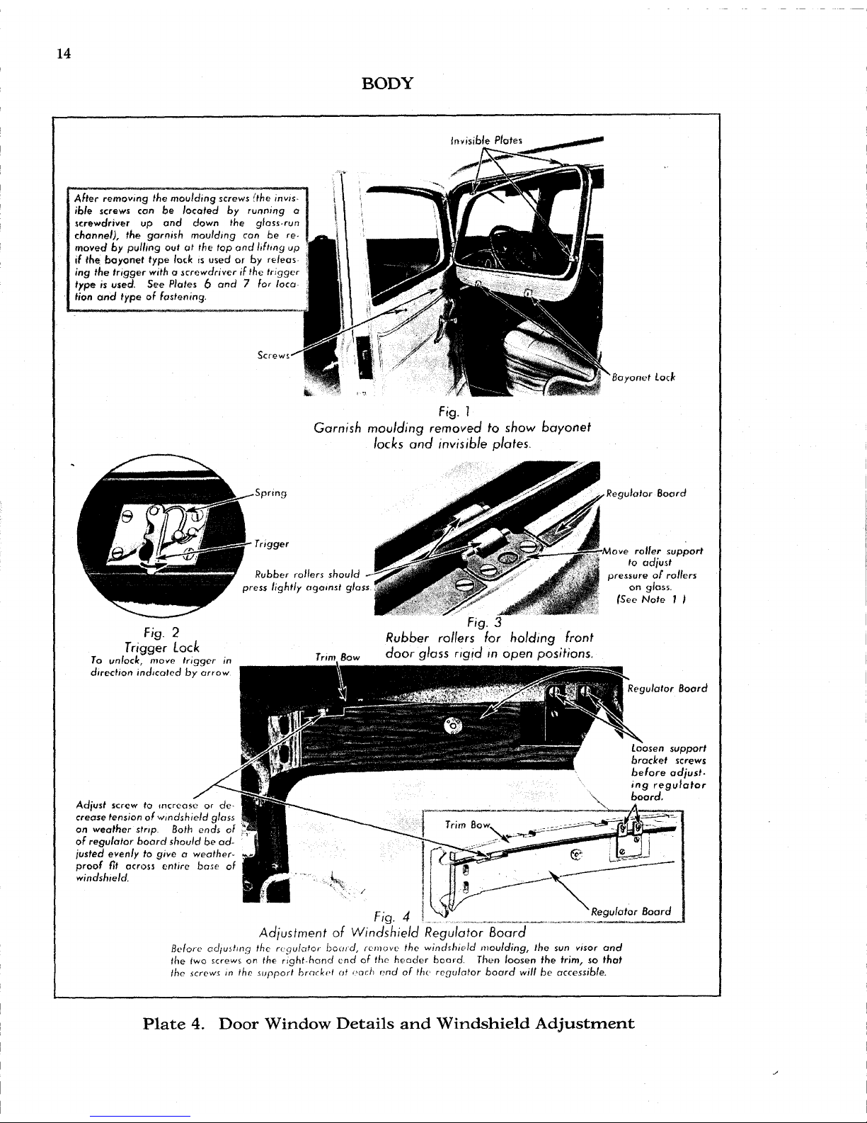
14
BODY
Invisible
Plates
After
removing the
moulding screws
(the
invis-
ible screws
can be
located
by
running
o
screwdriver up and down the
glass-run
channel),
the
garnish moulding
can be re-
moved
by
pulling
out at the top and
lifting up
if
the
bayonet
type
loclt is
used
or by
re/eas
ing
the
trigger
with a screwdriver
if
the trigger
type
is
used.
See
Plates
6 and 7 for
loco
Hon
and
type
of
fastening.
Screws
Bayonet
Lock
Fig.
I
Garnish moulding removed to show bayonet
locks and invisible
plates.
Spring
Trigger
Fig.
2
Trigger
Lock
To
unlock, move trigger
in
direct/on
indicated
by
arrow
Rubber rollers should
press lightly against glass
Trim
Bow
Regulator Board
•Move roller support
to adjust
pressure
of
rollers
on glass.
(See Note ) )
Fig.
3
Rubber rollers (or holding front
door
glass rigid in open positions.
Adjust
screw to
increase
or de-
crease
tension
of
windshield glass
on
weather strip. Both ends
of
of
regulator board should
be ad-
justed evenly
to
give a weather-
^
proof
fit
across entire base
of
windshield.
Regulator Board
loosen
support
bracket screws
before
adjust-
ing
regulator
board.
Fig.
4
Adjustment
of
Windshield Regulator Board
Before adjusting
the
regulator
board,
remove
the
windshield
moulding, the sun visor and
the
two
screws
on the
right-hand
end of the
header
board. Then loosen the trim, so
that
the screws
in the
support bracket
at
each
end of the
regulator board
will
be accessible.
Plate
4.
Door
Window
Details and
Windshield
Adjustment
Page 79
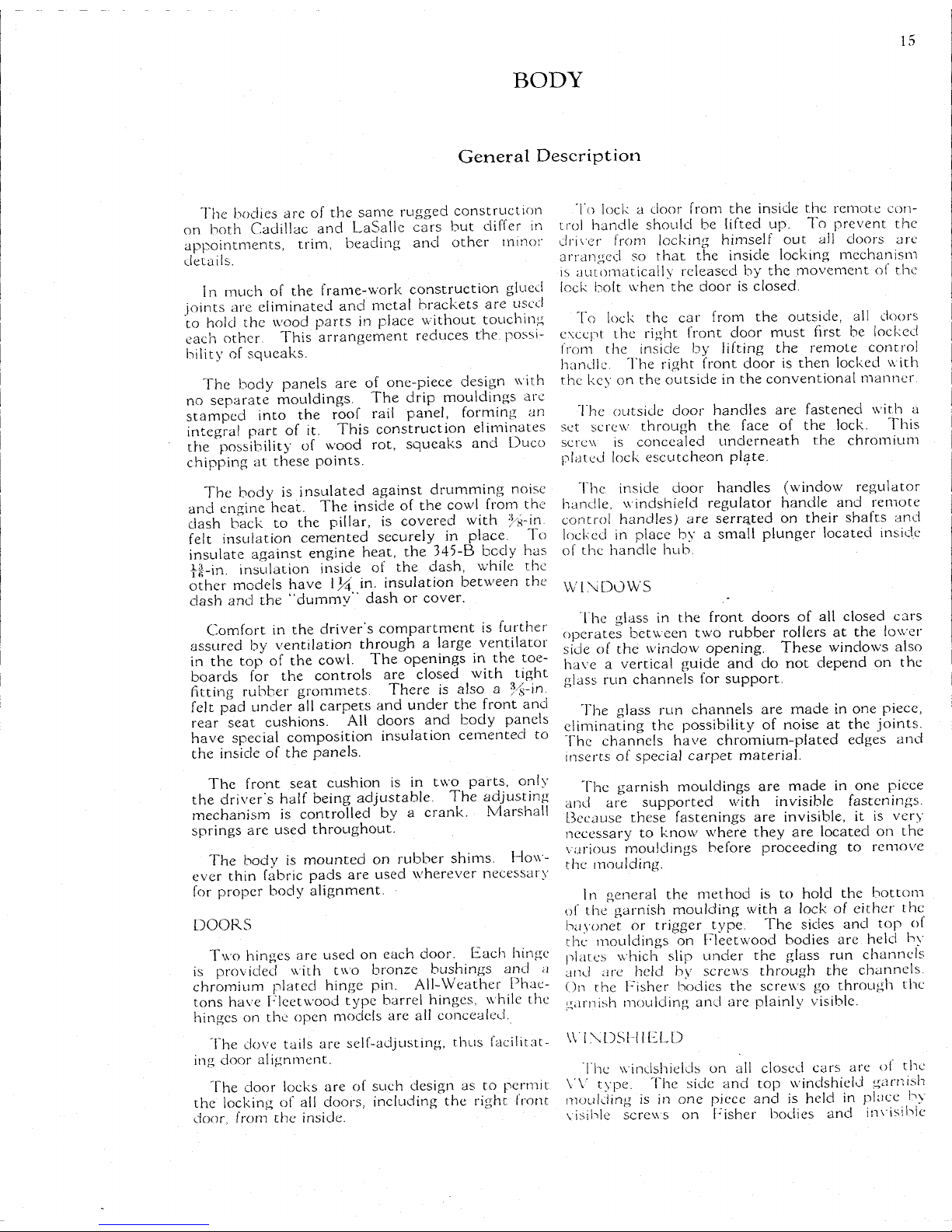
BODY
15
General
Description
The
bodies are of the
same
rugged construction
on
both
Cadillac
and
LaSalle
cars but
differ
in
appointments,
trim,
beading and other minor
details.
In
much of the frame-work construction glued
joints
are eliminated and metal brackets are used
to
hold
the wood
parts
in place without touching
each other.
This
arrangement reduces the. possi-
bility
of squeaks.
The
body panels are of one-piece design
with
no
separate
mouldings. The drip mouldings are
stamped into the
roof
rail
panel, forming an
integral
part
of it.
This
construction eliminates
the
possibility
of wood rot, squeaks and Duco
chipping
at
these
points.
The
body is insulated against drumming noise
and engine
heat.
The inside of the
cowl
from
the
dash back to the
pillar,
is covered
with
%-in.
felt
insulation cemented securely in place. To
insulate against engine
heat,
the 345-B body has
yg-in.
insulation inside of the dash,
while
the
other models have 1¼ in. insulation between the
clash
and the "dummy" dash or cover.
Comfort
in the driver's compartment is further
assured by ventilation through a large ventilator
in
the top of the
cowl.
The openings in the toe-
boards for the controls are closed
with
tight
fitting
rubber grommets. There is also a %-in.
felt
pad under all
carpets
and under the front and
rear
seat
cushions. All doors and body panels
have special composition insulation cemented to
the inside of the panels.
The
front
seat
cushion is in two parts,
only
the driver's
half
being adjustable. The adjusting
mechanism
is controlled by a crank.
Marshall
springs are used throughout.
The
body is mounted on rubber shims.
How-
ever thin fabric
pads
are used wherever necessary
for
proper body alignment.
DOORS
Two
hinges are used on each door.
Each
hinge
is
provided
with
two bronze bushings and a
chromium
plated hinge pin.
All-Weather
Phae-
tons
have Fleetwood type barrel hinges,
while
the
hinges on the open models are ail concealed.
1 he dove tails are self-adjusting,
thus
facilitat-
ing
door alignment.
1 he door locks are of such design as to permit
the
locking
of all doors,
including
the right front
door,
from
the inside.
1 o lock
a door
from
the inside the remote con-
trol
handle should be
lifted
up. To prevent the
driver
from
locking
himself
out ail doors are
arranged so
that
the inside
locking
mechanism
is
automatically released by the movement of the
lock
bolt when the door is closed.
To
lock
the car
from
the outside, all doors
except the right front door must first be
locked
from
the inside by
lifting
the remoLe control
handle. The right front door is then
locked
with
the key on the outside in the conventional manner.
"I
he outside door handles are fastened
with
a
set screw through the face of the
lock.
This
screw
is concealed underneath the chromium
plated
lock
escutcheon plate.
The
inside door handles (window regulator
handle, windshield regulator handle and remote
control
handles) are serrated on their shafts and
locked
in place by a
small
plunger located inside
of
the handle hub.
WINDOWS
The
glass in the front doors of all closed cars
operates
between two rubber rollers at the lower
side of the window opening. These windows also
have a vertical guide and do not depend on the
glass run channels for support.
The
glass run channels are made in one piece,
eliminating
the
possibility
of noise at the joints.
The
channels have chromium-plated
edges
and
inserts of special carpet material.
The
garnish mouldings are made in one piece
and are supported
with
invisible
fastenings.
Because
these
fastenings are
invisible,
it is very
necessary to know where they are located on the
various
mouldings before proceeding to remove
the moulding.
In
general the method is to
hold
the bottom
of
the garnish moulding
with a lock
of either the
bayonet or trigger type. The sides and top of
the mouldings on Fleetwood bodies are held by
plates
which
slip
under the glass run channels
and are held by screws through the channels.
On
the Fisher bodies the screws go through the
garnish
moulding and are
plainly
visible.
WINDS I HELD
The
windshields on all closed cars are ol the
VV
type. The side and top windshield garnish
moulding
is in one piece and is held in place by
visible
screws on lusher bodies and
invisible
Page 80

16
BODY
Chfomiuni
Plated
Hm
qo
Pin
Typical Body Mountings
Tighten body bolt
(ust
enough
to
flatten
lock
washer.
Chock alignment
of doo
during
this operation
Use
thtn fahrtc
shims
on top of
rubber shims when necessary
to
ohgn
doors.
Fig.
2
View
of
door hinge with insert
showing bronze bushings.
Window Regulator Handle
Remote Control Handle
\
Escutcheon
Plate
Fig.
3
Set scrr-w
for
oulsidi- door
/><;,,,.'/.-
i-srutrheon plate
Plate
must
hi- i
umli-
doo,
SeJ'Screw
Fig. 4
Removing
Inside
Door Handle
The
trr.lHe door handles
and
w,nd:,h't.-ler
II-QUIOU
hanrjle
are
serrated
on
their shafts
::nd
tod.*,-!
,
,,lrjce
by o
sn:all plunger
heateJ
,ns„l-
of th
i-ernllu
hub lo
remove
the
hand-u
-.1
>,
ti---f
;:oi
to release
//.,.
phir.rjei
«r.ffl »/>. •:.:1
,*>r,w
ob,ove
Plate
5.
Body
Mounting
and
Door
Details
Page 81

17
BODY—General
Description—Service Information
plates on Fleetwood bodies. The top and back
panels on both body types are held in place by
invisible
fastenings.
The
windshield cleaner is of the swinging arm
type
with
two arms operated in tandem by a
single
motor on the outside of the windshield
regulator board. The tandem linkage is between
the windshield regulator board and the steel
header.
The
rear
view
mirror is of the ball-joint type
and is fastened to the lower
edge
of the windshield
regulator board on the closed cars.
Service
Information
1.
Adjusting
Window
Guide
Roller
1
he guide rollers at the lower
edge
of the front door
windows are adjusted by removing the garnish moulding and
moving
the inside
roller
closer to or farther away
from
the
window
glass. When properly adjusted the
roller
should
press against the glass just enough to
hold
it. If the
roller
is
adjusted so tight
that
it slides instead of turning, the glass
may
be marked. In some
cases
when the
roller
must be
backed
off, it
will
necessitate cutting some material
from
the
garnish
moulding to
allow
sufficient clearance for the roller.
2.
Body
Bolts
for Service
In
order to
minimize
the number of body bolt sizes necessary to stock, the body bolts for service are supplied in standard
lengths of 3½, 5½ and 7% inches. Not all bolts used in
production
are of
these
lengths. Therefore, when replacing
body
bolts, it is necessary to measure the old bolts and select
new ones of corresponding lengths or of lengths
nearest
to
that,
of the old bolts. The bolts selected should be
long
enough
to permit proper adjustment
which
is necessary
with
the
rubber body shims.
3.
Care of Top Coverings
The
only
attention required by top coverings, aside
from
periodic
inspection for checks and possible leaks, is an occas-
ional
cleaning
with
clear water.
The
use of top dressings on the top is not recommended,
either to restore the lustre or to prevent leaks. Neither is a
top dressing recommended as a preventive of deterioration,
as most dressings contain some sort of solvent
that
causes
the top covering to deteriorate.
Grease and oil
will
also damage top material. It is im-
portant therefore to
avoid
the use of
oils
of any nature,
including
kerosene, mineral
oils,
vegetable
oils,
animal
oils
or
waxes. For this reason also,
avoid
the use of oil in
elim-
inating
squeaks in the
roof
construction.
4.
Cleaning
Khaki
Top Materials
Top
dressing of any
kind
and cleaning
fluids
containing
oil,
naptha, gasoline, energine, strong chemicals, or any other
liquid
which
will
dissolve rubber, should never be used on
the
khaki
top material of convertible and open models. As
these
tops are made of double texture material impregnated
with
rubber, such preparations
would
disintegrate the rubber
content and
ruin
the fabric.
The
safest cleaning method is to use warm water and a
sponge or brush; if necessary,
ivory
soap may be applied
sparingly,
but care must be taken
that
all the soap is washed
off.
Most
of the
soiled
spots can be cleaned up by using
only
a piece of clean art gum or pure gum rubber.
It is also important to see
that
the top material is thor-
oughly
dry before the top is lowered.
5.
Cleaning
Car Upholstery
Care
must be exercised in cleaning upholstery material
and
floor
carpets used in car interiors. Some ol the fabrics
arc impregnated
with
a rubber backing,
originally
applied as a
solution,
which
binds the nap securely. Use of too much
cleaning
fluid
tends
to dissolve this backing,
thus
loosening
the nap.
lo
avoid
this, cleaning
fluids
should be used sparingly on
any upholstery, especially
pile.
An additional safeguard is the
use of factory-approved
fluids
which
are selected for their
factor
of safety as
well
as for
efficiency
in cleaning.
Water
stains on upholstery material can easily be removed
by
brushing off the material thoroughly and then cleaning it
with a cloth
dampened
with
Cadillac
cleaner. The cleaner
should
be used sparingly. Let the upholstery dry and smooth
over
lightly
with
a very hot
iron
applied through a damp
cloth.
6. Cleaning Chromium-Plated
Parts
While
chromium-plated
parts
do not require repeated
polishing
like
nickel,
they should be cleaned occasionally to
restore the lustre and protect the plating
from
deterioration.
It is particularly important to clean the plated
parts
on
the chassis,
which
are exposed to the road elements. In
winter,
salt and
calcium
chloride, used on the
streets
to remove
ice
,are splashed upon the car, and in summer, the same is
true
of dust-laying chemicals. Frequent cleaning
will
prevent
these
chemicals
from
acting on the plating.
Chromium-plated
parts
which
have been subjected to the
action
of chemicals of this sort may require more than clean-
ing,
depending upon the length of time and the strength of
the chemicals. In such cases,
polishing
with
a good metal
polish
will
usually remove the discoloration and restore the
iustre.
Wiping
with a cloth
dampened in kerosene
will
help to protect the plating
from
further deterioration.
Discoloration
of chromium-plated
parts
under the action
of
chemicals used on roads and pavements, is not an abnormal
condition
and is not an indication of defective plating.
7. Door Bumper
Adjustment
Adjustment
of the doors is made by means of different
lengths of rubber bumpers. Three lengths of bumpers are
available
and can be used interchangeably as necessary to
suit
each
individual
case.
On
the first cars shipped, no bumper plates are provided
on
the doors and the
following
bumpers must be used:
Identification
Number
l-irst-tvpe
Bumper on Bumper Part No.
Short
bumper
I
OVA
400233«
Medium
bumper 107C 40235b8
Long
bumper 107B 4024073
Later
cars have bumper plates, Part No. 4220157, on the
doors to increase the tension of the bumper on the doors in
the closed position.
The
second-type bumpers listed below must, be used
with
i
hese
plates:
Identification
Number
Second-tvpc
Bumper on Bumper Parr No.
Short
bumper 208 4018317
Medium
bumper 209 4(103348
Long
bumper 210 402o(144
Second-type bumpers may be used on early cars by
installing
bumper plates on the doors. These may be installed where
ihc,
bumper strikes the door by
drilling
the screw hole using
Page 82

18
BODY—Service
Information
the bumper plate as a template and attaching the plate
with
the screws provided
with
the plate under Part No. 4220157.
Bumpers
of the length suitable lor the particular cars should
be selected.
No
attempt
should be made to use the first-type bumpers
on
later cars
with
the bumper plates as a different shaped
bumper is required. Neither should the second-type bumper
be used on early cars without the bumper plate as they
will
not have the proper tension on the doors.
8. Installing
Cowl
Bead
The
cowl
bead is attached by concealed fastenings. Two
types of
these
fastenings have been used.
On
the first bodies assembled the bead is held at each end
by a long
bolt
which
goes
through the
sill
and screws into a
tapped plate close to the end of the bead. On later bodies a
stud is used
which
is a
part
of the bead itself.
This
stud
goes
through the
same
hole in the
sill
that
was used for the
bolt
on the first type bead and is anchored
with
a nut.
When
installing
a new
cowl
bead
only
the second type
should
be used. The bolt or nut holding the bead in place
can
be reached
with
a universal wrench. 1 f the stud extends
through the nut too far, it should be cut off.
When
installing
a bead, the bolt or nut should be drawn
up just enough to
hold
the bead snugly in place. If drawn
too tight, the end of the bead may buckle or break.
9. Installing Outside
Door
Handles
When
the door handles are installed on a car, a
small
spring
washer, Part number 4023713, is installed on the shaft
to take up end play.
Ordinarily,
when the handle is removed,
the washer remains in place on the end of the handle, but in
some
cases
it may remain inside and drop down in a crevice.
If
the door handle is removed for any reason, care should
be taken to see
that
the washer is in place when the handle is
reinstalled,
or a new washer should be installed.
10. Installing
Hood
Corner Protectors
When
installing
the rubber hood corner protectors it is
important
that
the button be
pulled
all the way through the
hole
in the hood. The proper method of
installing
these
protectors is first to
slip
the flange over the
edge
of the hood
and then
pull
the button through the hole in the hood
with
a
pair
of narrow long-nosed pincers.
Both
edges
of the button
should
be squeezed
together
when
pulling
the button through
the hole. If
only
one
edge
of the button is grasped, the
edge
may
be torn as it is
pulled
through.
11.
Installing
Window
Regulator Handle on
Left
Front
Door
I
he proper position lor the window regulator handle on
the left front door is parallel
with
the remote control handle
in
the unlocked position when the window is turned all the
way
up.
This
is necessary
with
first type cars to eliminate
the
possibility
of interference between the driver's hand on
the steering wheel and the knob of the window regulator
handle.
If
it is found
that
the window regulator handle is not in
this position, it should be removed and properly reinstalled.
Before
taking the handle off, run the window up as far as it
will
go. Release the spring retaining pin in the handle using
tool
number
B-127.
Reinstall
the handle in such a position
that
it
will
be parallel
with
the remote control handle when it
is
in the unlocked position.
12.
Removing
Windshield
Weather Strip
The
rubber strip in
which
the windshield is imbedded in
the closed position has a chromium plated bead
rolled
on to
its front
edge
and this bead is attached to the bead running
around the entire windshield by a piece of connecting wire
inserted in the ends. A
part
of the rubber strip
itself
is held
in a recess
in the top of the
cowl
bar.
If
this rubber is to be removed for any reason, first remove
the ash receiver and the windshield moulding above the
instrument panel. Then raise the windshield to clear the
rubber and insert a flat
tool
under the rubber at about the
center of the strip and
from
the front side of the car.
Raise
the strip carefully and
pull
the chromium plated bead
away
from
the wire
which
holds it to the bead on the sides of
the windshield. Use particular care not to
kink
the bead
when
lifting
it in this manner.
To
reinstall the rubber strip, keep the bead bowed
slightly
and insert the corner wires in the
ends
of the bead, gently
pressing the strip into place. When the strip is in place,
seal
the
ends
securely against the side windshield panels
with
a sufficient amount of "rubber dough" to prevent
leakage.
13.
Door
Garnish
Moulding
Fastenings on
AU-Weather
Phaeton and Convertible Coupes
On
all-weather phaetons, the door garnish mouldings are
held
in place by
three
trigger locks on the front doors and by
two
trigger locks on the rear doors.
The
door garnish mouldings on Convertible Coupes are
held
in place by
three
trigger
locks.
Page 83

BODY—Type
and Job Numbers
19
FISHER
AND
FLEETWOOD
BODY TYPE
AND JOB
NUMBERS
When
ordering chassis
parts
affected by wheelbase, the
BODY
JOB
NUMBER
must
be given the
same
as when ordering body
parts
Body
Type
•Job
Number Wheelbase
345-B
(LaSalle)
Fisher
Bodies
2-Pass. Coupe
2-Pass. Convertible Coupe.
5-Pass.
Town
Coupe
5-Pass.
Sedan
5-Pass.
Town
Sedan
7-Pass. Sedan
7-Pass. Imperial Sedan. . . .
355-B
(Cadillac)
Fisher
Bodies
2-Pass. Roadster
2-Pass. Coupe
2-Pass. Convertible Coupe
5-Pass.
Sedan
5-Pass.
Phaeton
5-Pass.
Phaeton
with
Sliding
Windshield
5-Pass.
AU-Weather
Phaeton...
5-Pass.
Sport Phaeton
5-Pass.
Coupe
5-Pass.
Sedan
5-Pass.
Town
Sedan
7-Pass. Sedan
7-Pass. Imperial Sedan
Fleetwood
Bodies
5-Pass.
Two-Door
Close
Coupled
Town
Coupe
5-Pass.
Sedan
5 Pass.
Town
Car
with
Opera
Seats—leather
back
7-Pass. Sedan
t7-Pass. Transformable Cabriolet
7-Pass. Imperial Sedan
*7-Pass. Imperial Sedan
f7-Pass.
Imperial Sedan
7-Pass.
Town
Car—leather back.
7-Pass.
Town
Car—metal back..
370-B
(Cadillac)
Fisher
Bodies
2-Pass. Roadster
2-Pass. Coupe
2-Pass. Convertible Coupe
5-Pass.
Sedan
5-Pass.
Phaeton
5-Pass.
Phaeton
with
Sliding
Windshield
5-Pass.
AU-Weather
Phaeton.. . .
5-Pass.
Sport Phaeton
5-Pass.
Coupe
5-Pass.
Sedan
5-Pass.
Town
Sedan
7-Pass. Sedan
7-Pass. Imperial Sedan
Fleetwood
Bodies
5-Pass.
Two-Door
Close
Coupled
j
32-678
32-668
32-672
32-659
32-b52
32-662
32-663
32-8-155
32-8-178
32-8-168
32-8-159
32-8-256
32-8-280
32-8-273
32-8-279
32-8-272
32-8-259
32-8-252
32-8-262
32-8-263
32-8-222
32-8-209
32-8-225
32-8-212
4925
32-8-213
4975-H-4
4985
32-8-227
32-8-226
32-
12
•155
134"
32-
12
178
134"
32-
12 168
134"
32-
12 159
134"
32-
12
25b
140"
32-
12
280
140"
32-
12
273
140"
32-
12
279
140"
32-
12 272
140"
32-
12
259
140"
32-
12
252
1
40"
32-
12
2b2
140?
32-
12
203
!
40"
130"
130"
130"
130"
136"
136"
136"
134"
134"
134"
134"
140"
140"
140"
140"
140"
140"
140"
140"
140"
140"
140"
140"
140"
140"
140"
140"
140"
140"
140"
Body
Type
ijob
Number
jWheelbase
fown
Coupe.
32-12-222
140"
Fleetwood
Bodies-
Continued
t5-Pass
Convertible Coupe
5-Pass.
Sedan
t5-Pass. Imperial Cabriolet
f5-Pass.
Sedan-—metal back
5-Pass.
Town
Car
with
Opera
Seats—leather
back
f5-Pass.
Imperial Sedan
with
Solid
Rear Quarter—leather
back
t5-Pass. Imperial Sedan
with
Fold-
ing
Rear Quarter—leather back
t5-Pass. Imperial Sedan—metal
back
f7-Pass.
Phaeton
7-Pass. Sedan
t7-Pass. Imperial Sedan
f7-Pass.
Imperial Sedan
7-Pass. Imperial Sedan
*7-Pass. Imperial Sedan
7-Pass.
Town
Car-—leather back.
7-Pass
Town
Car-—metal back..
f7-Pass.
Imperial Cabriolet
452-B
(Cadillac)
Fisher
Bodies
2-Pass, Roadster
2-Pass. Coupe.
2-Pass. Convertible Coupe
5-Pass.
Sedan
5-Pass.
Phaeton
5-Pass
Phaeton
with
Sliding
Windshield
5-Pass.
AU-Weather
Phaeton. . . .
5-Pass.
Sport Phaeton
Fleetwood
Bodies
5-Pass.
Two-door
Close
Coupled
Town
Coupe
t5-Pass. Convertible Coupe
f5-Pass.
Imperial Sedan
f5-Pass.
Imperial Cabriolet
5-Pass.
Sedan
f
5-Pass.
Sedan—metal back
t5-Pass.
Special
Sedan
5-Pass.
Town
Car
with
Opera
Seats—leather
back
|5-Pass. Imperial Sedan — metal
back
•(•5-Pass. Imperial Sedan
with
Solid
Rear
Quarter—leather back.. .
•(5-Pass. Imperial Sedan
with
Fold-
ing
Rear Quarter—leather back
t5-Pass. Imperial Cabriolet
7-Pass. Sedan
7-Pass. Imperial Sedan
*7-Pass. Imperial Sedan
7-Pass.
Town
Car-—leather back.
7-Pass.
Town
Car—metal back..
t7-Pass. Transformable Cabriolet.
f7-Pass.
Imperial Landaulet
f8-Pass.
Imperial Sedan
5085
32-12-209
5030FL
503 IS
32-12-225
5055
5055C
5031
5057
32-12-212
5030
5065
32-12-213
5075H4
32-12-227
32-12-226
5075FL
32-16-222
5185
5129
5130FL
32-16-209
5I3IS
5140B
32-16-225
5131
5155
5155C
515bC
32-16-212
32-16-213
5175H4
32-16-227
32-16-220
5125
5165
5177
1
40"
140"
140"
I
40"
140"
140"
140"
140"
140"
140"
140"
140"
140"
140"
140"
140"
140"
32-16-155
143"
32-
16-178
143"
32-
16-108
143"
32-
16-159
143"
32-
16-256
149"
32-
16-280
149"
32-
16-273
149"
32-
16-279
149"
149"
149"
149"
149"
149"
149"
149"
149"
I
49"
149"
149"
149"
149"
I
49"
149'
149"
149"
149"
I
49"
U-o"
*Same as regular Fleetwood bodies but
with
4 inches more headroom.
fSpecial
bodies.
Page 84
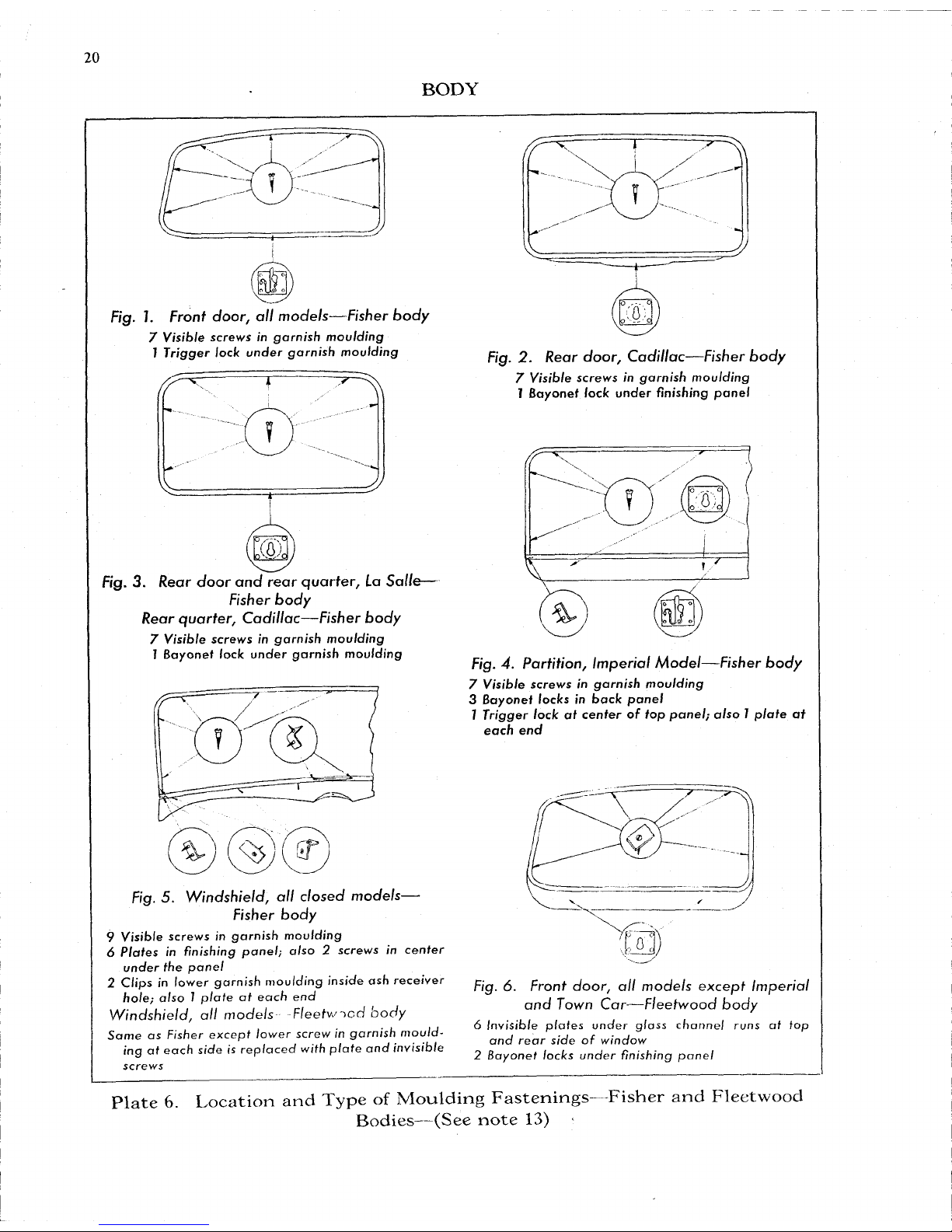
20
BODY
Fig.
I.
Front door,
all
models—Fisher body
7 Visible screws
in
garnish moulding
1
Trigger lock under garnish moulding
Fig.
3
Rear door and rear quarter,
La
Salle—
Fisher body
Rear
quarter,
Cadillac—Fisher body
7 Visible screws
in
garnish moulding
7 Bayonet lock under garnish moulding
Fig.
5.
Windshield,
all
closed models—
Fisher body
9 Visible screws
in
garnish moulding
6
Plates
in
finishing
panel}
also 2 screws
in
center
under
the
panel
2
Clips
in
lower garnish moulding inside
ash
receiver
hole; also 1 plate
at
each
end
Windshield,
all
models Fleetwood body
Same
as
Fisher except lower
screw in
garnish mould-
ing
at
each
side
is
replaced with
plate
and
invisible
screws
Fig.
2.
Rear door, Cadillac—Fisher body
7 Visible screws
in
garnish moulding
7 Bayonet lock under finishing panel
o
,-, o
.',0).
fig. 4.
Partition,
Imperial Model—Fisher body
7 Visible screws
in
garnish moulding
3
Bayonet locks in back panel
7
Trigger lock
at
center
of top
panel;
also 7 plate
at
each
end
Fig.
6.
Front door,
all
models except Imperial
and Town Car—Fleetwood body
6
Invisible
plates under glass
channel
runs
at top
and rear side
of
window
2 Bayonet locks under finishing panel
Plate
6.
Location
and
Type
of
Moulding
Fastenings- Fisher
and
Fleetwood
Bodies—(See
note
13)
Page 85

21
BODY
Fig.
7.
Front
door,
Imperial
and Town
Car—
Fleetwood
body
6
Invisible
plates under glass channel runs
at top and
rear side
of
window
1
Trigger lock under garnish moulding
Fig. 2.
Rear
door,
all models—Fleetwood
bodies
4
Invisible
plates under glass channel runs
2 Bayonet locks under finishing panel
Fig. 3.
Rear
quarter,
all models—Fleetwood
body
4
Invisible
plates under glass channel runs
2 Bayonet locks under finishing panel
Fig. 5. Arm
rest,
all models—Fleetwood body
1
Bayonet lock
at
center;
also small brad
in
lower
corner of
panel.
To
remove panel drive brad
through panel
and
lift
up
Fig. 4.
Partition,
Imperial
Model—Fleetwood
body
9
Invisible
plates under glass channel
run
3
Bayonet locks under back panel
7
Trigger lock
at
center
of top
panel;
also 7 plate
at
each
end
Fig. 6. Front
seat,
all models—Fleetwood body
3
Bayonet locks under back panel
3
Trigger locks under
top
panel
Plate 7.
Location
and
Type
of
Moulding
Fastenings—Fleetwood Bodies
Page 86

21A
BODY-—Type
and Job
Numbers
FISHER
AND
FLEETWOOD
BODY
TYPE
AND JOB
NUMBERS
FOR
SERIES
CARS
345-C
(LaSalle)
Fisher
Bodies
2-Pass.
Coupe
2-Pass.
Convertible Coupe
5-Pass.
Town
Coupe
5-Pass.
Sedan
5-Pass.
Town
Sedan
7-Pass. Sedan
7-Pass. Imperial Sedan...
355-C
(Cadillac)
Fisher
Bodies
2-Pass. Roadster
2-Pass.
Coupe
2-Pass.
Convertible Coupe...
5-Pass.
Phaeton
5-Pass.
All-Weather
Phaeton.
5-Pass.
Coupe
5-Pass.
Sedan
5-Pass.
Town
Sedan
7-Pass. Sedan
7-Pass. Imperial Sedan
Fleetwood
Bodies
Opera
5-Pass.
Sedan
5-Pass.
Town
Car
with
Seats—leather
back
7-Pass. Sedan
7-Pass. Imperial Sedan
7-Pass.
Town
Car—leather back
7-Pass.
Town
Car—metal back.
370-C
(Cadillac)
Fisher
Bodies
2-Pass.
Roadster.
2-Pass.
Coupe... .
33-678
130"
33-668
130"
33-672
130"
33-659
130"
33-652
136"
33-662
136"
33-663
136"
33-8-155
134"
33-8-178
134"
33-8-168
134"
33-8-256
140"
33-8-273
140"
33-8-272
140"
33-8-259
140"
33-8-252
140"
33-8-262
140"
33-8-263
140"
33-8-209
140"
33-8-225
33-8-212
33-8-213
33-8-227
33-8-226
33-12-155
33-12-178
140"
140"
140"
140"
140"
134"
134"
Fisher
Bodies—Continued
2-Pass. Convertible Coupe... .
5-Pass.
Phaeton
5-Pass.
All-Weather
Phaeton..
5-Pass.
Coupe
5-Pass.
Sedan
5-Pass.
Town
Sedan
7-Pass. Sedan
7-Pass. Imperial Sedan
Fleetwood
Bodies
Opera
1
5-Pass.
Sedan
5-Pass.
Town
Car
with
Seats—leather
back
7-Pass. Sedan
7-Pass. Imperial Sedan.. .
7-Pass.
Town
Car—leather back.
7-Pass.
Town
Car—metal back
452-C
(Cadillac)
Fisher
Bodies
2-Pass. Roadster
2-Pass. Coupe
2-Pass. Convertible Coupe.. .
5-Pass.
Phaeton
5-Pass.
All-Weather
Phaeton
Fleetwood
Bodies
Opera
5-Pass.
Sedan
5-Pass.
Town
Car
with
Seats—leather
back
7-Pass. Sedan
7-Pass. Imperial Sedan...
7-Pass.
Town
Car—leather back.
7-Pass.
Town
Car—metal back.
33-12-168
134"
33-12-256
140"
33-12-273
140"
33-12-272
140"
33-12-259
140"
33-12-252
140"
33-12-262
140"
33-12-263
140"
33-12-209
140"
33-12-225
140"
33-12-212
140"
33-12-213
140"
33-12-227
140"
33-12-226
140"
33-16-155
33-16-178
33-16-168
33-16-256
33-16-273
33-16-209
149"
33-16-225
149"
33-16-212
149"
33-16-213
149"
33-16-227
149"
33-16-226
149"
143"
143"
143"
149"
149"
August
1933
Page 87
21B
BODY—General
Description—Service
Information
4i
General
Description
The bodies on the "C" series cars are of the
same
rugged construction but differ in appoint-
ments
and other minor details. They embody a
number of new
features
including the Fisher No-
Draft
(I. C. V.) ventilating system.
The No-Draft ventilating system includes
pivoting
glass panels in the front door and rear
quarter windows on all 5-and
7-passenger
sedans
and the rear doors on
Town
sedans
and
Town
cars,
and the
cowl
ventilator
which
is baffled and
drained in such a way as to be completely rainproof. The ventilating panels are controlled by
handles or cranks conveniently located just below
the window. The rear quarter windows are
stationary. All window ventilator controls are
worm-geared for easy operation.
There are two types of front doors,
which
differ
in
the window and ventilator construction.
With
the first type doors, it is necessary to lower the
window
glass far enough to disengage it from the
Ventilating
panel before the ventilating panel can
be opened or closed. The window glass, however,
can
be raised or lowered as desired.
The second type doors have a stationary
division
channel between the ventilator and the
window
glass so
that
the ventilating panels can be
opened or closed independently of the window
glass.
The garnish mouldings are
similar
to
those
used
on
the "B" cars but the method of retaining them
in
place differs in
that
there
are no
invisible
fastenings at the sides and top.
Visible
screws are
used at
these
points for holding the garnish
mouldings
in position.
The trigger type
lock
is employed at the lower
side of the garnish mouldings on all door windows
while
a bayonet
lock
is used at the rear quarter
windows.
The garnish moulding
finishing
panels are
separate
from the garnish mouldings on the "C"
series
Cadillac
bodies. These panels on early cars
are held in place by bayonet locks such as used on
the garnish mouldings. On later cars, hanger
plates are also used in addition to the bayonet
locks
for fastening the
finishing
panels in place.
Service
Information
14.
Replacing
Ventilator
Glass
Replacement of the ventilator glass is the
same
on all cars
and can be accomplished without removing the ventilator
assembly or disturbing the garnish moulding or control handle.
Since
the glass is a tight
press
fit in the channel, special tools
should
be used for removing and installing it.
The removal of the ventilator glass requires the use of a
puller,
Part No.
B-176.
If the
ventilator glass
is to he rein-
stalled
or used again,
friction
tape
should be used between the
puller
clamp and the glass to prevent the clamp from marring
or
scratching the glass surface.
The glass is installed by pushing it into the channel using the
replacing
tool,
Part No.
B-175.
Before installing a ventilator
glass, first place 2-inch strips of glass
filler
over the top and
bottom
edges
of the glass, arranging the strips at the rear end
of
the
edge
so
that
they
will
come under the
ends
of the
channel when the glass is installed in position. Then wrap
the
three
edges
of the glass
that
go in the channel
with
a
single
strip of the glass
filler.
This
filler
is a special
tape
ob-
tainable from the Factory Parts
Division
in rolls of any
length desired. Two thicknesses of this
filler
tape
are
avail-
able.
Thin
filler
can be secured under Part No. 4035726 and
medium
filler
under Part No. 4035727. If necessary, in ex-
treme
cases, two thicknesses of thin
filler
can be tised.
After
wrapping the glass
with
the
filler,
spring the two
ends
of
the glass channel slightly
together
or toward each other and
start
the glass in the channel a few inches by hand, placing the
glass in the lower end first and then forcing it into the upper
end.
If
cither the top or the bottom
edge
of the glass feeds in
faster than the other one when forcing the glass into the
channel, the replacing
tool
should be adjusted up or down to
change the
pressure
point, bringing it closer to the
edge
which
is
lagging. The lagging
edge
should also be tapped gently
with
a block of wood and hammer to assist in forcing the glass
evenly
into the channel. The glass should be pressed in even
with
both
ends
of the glass channel.
The
ends
of the channel arc then pressed down on the glass
and the
ends
of the glass
filler
trimmed off even
with
the
edge
of
the channel.
If
the weather strip loosens from the retainer, it should be
cemented in place
with
FS-681 ventilator cement and allowed
to dry for at least an hour under pressure.
15.
Removing
Ventilator
Control Handle
Two
different types of control handles arc used for operating
the No-Draft ventilators. The early handles arc of the T-type
while
the later handles are of the crank type. Two methods
of
mounting
these
handles are used. One type of mounting
is
used when the regulator control shaft
passes
through the
belt
finishing
panel and the other type is used on cars where
the
finishing
panel is omitted.
With
the first type mounting the handle is fastened to the
finishing
panel by
means
of lugs or wood screws and merely
slides
on the regulator shaft when the panel is installed in
position.
This handle is, therefore, removed and installed
with
the
finishing
panel.
August
Page 88

21C
BODY
Weather Strip
Retainer-
Weather
Strip-
Lock
Board-
Lower window glass
when working on-^
ventilator
Retqining
Screws
in Lift Cam
To
adjust
ventilator,
remove garnish moulding
and trim and tighten or loosen adjusting screw
as necessary
Remove
damaged
ventila-
tor glass
with
puller,
Part
No.
B-176.
Install
venti-
lator glass
with
replacing
tool,
Part
No. B-175
Regulator
Fig. '
First
Type
Fronf
Door
with
garnish
moulding
and trim removed
To
remove
regulator
without
removing
lock
board, drill two IJ2 in. holes in lock
board
to gain access to lower screws
hold-
ing
regulator in place
Stationary
Division
Channel
Glass Run Channel
Fig. 2
Second
Type
Fronf
Door
with
garnish moulding and trim removed
Retaining
Screws
in Lift Cam
When
removing window glass, loosen lower end of stationary
divi-
sion
channel
and
swing
out of
position
to get
glass
out of
channel
Plate
7A.
Front
Door
Details—"C"
Series
Cars
August
1933
Page 89

21D
BODY—Servic
The removal of this type handle from the
finishing
panel is
only a matter
of straightening out or grinding off the lugs or
removing
the screws and
pulling
it out of the panel.
With
the second type mounting the handle locks to the
regulator control shaft
with
a small plunger located inside the
hub. The removal of this type handle requires the use of the
same
special tool No.
HMB-127
for releasing the
lock
plunger,
as for the inside door handles.
16.
Fastenings
for Door Finishing
Panels
The door
finishing
panels used on later "C" series
Cadillac
cars are held in place by two hangar plates in addition to the
bayonet type fastenings used on earlier cars. These hangar
plates are attached by
means
of screws to the rear face of the
finishing
panel and over the regulator board, and the screws
holding
the plates to this board must be removed to take out
the panel. This construction
assures
against loosening.
In
any
case
of the door
finishing
panel loosening up on early
cars
these
hangars
can be easily installed. The
parts
required
for
each panel are as
follows:
No.
Req. Name Part No.
2
Hangar plate 4038003
6 Screws 129186
17.
Position
of Door
Handles
v
Attention should be given to the position of the various
handles on the doors for the
greatest
convenience of the
operator.
All
handles should be placed so
that
they
lock
in the closed
position
on the downward swing. This gives the operator the
most advantageous leverage in
locking
the ventilators to
prevent leaks.
The door window regulator handles should be placed in
such
a position
that
they point away from the I. C. V. handle
when
the window is all the way up. This position affords
more clearance between the ventilator handle and the window
regulator handle when the window is all the way up or down.
18.
Replacing
Ventilator
Assembly
The replacement of the ventilator assembly necessarily requires the removal of the old ventilator from the car and the
installation
of the new one. This
necessitates
the removal and
installation
of the garnish moulding, the belt
finishing
panel
(on
cars using
finishing
panels) and the
trim.
It is not
necessary, however, to remove the
trim
panel entirely but
merely
to loosen it around the window and
lock
board, or
regulator board as in the
case
of the rear quarter windows,
and
pull
it away from the door or body far enough to provide
easy access to the ventilator and board assemblies.
19.
Replacing
Door
Ventilators
The removal and installation of the door ventilator and
regulator assemblies are practically the
same
on all cars.
There are, however, slight differences in operation between
the first and second type front doors and also between the
second type front doors and the rear doors. The removal and
installation
of
these
assemblies should be performed in the
following
way. See Plates 7A and 7B.
1. Remove garnish moulding. This includes the auxiliary
moulding
strip between the ventilator and the window glass
on
rear doors.
2.
Remove belt
finishing
panel. (Cars provided
with
finishing
panels.)
3.
Remove ventilator control handle. (Cars not provided
with
belt
finishing
panels.)
4. Remove inside door handles.
August
1933
Information
5. Loosen
trim
around window and slightly below
lock
board and
pull
away from door far enough to make
lock
board
accessible.
6. Remove
filler
board at top of
lock
board. (Front doors
only.)
7. Remove
nail
in each end of rubber weather strip. (First
type front doors only.)
8. Remove retaining screws in weather strip retainer (ten
screws in front door and six in rear door). Screws are indicated
by
short arrows in Fig. 1.
9. Remove ventilator assembly by
pulling
out at the top
and
lifting
up to disengage drive shaft from regulator.
10.
Remove
lock
board, including corner blocks, and
regulator.
The installation of the ventilator assemblies and regulators
is
accomplished in the opposite order of their removal.
When
installing the first type front door ventilator assembly,
be
sure
to
install
the metal
clip
at the top end of the weather
strip and to
nail
both
ends
of the weather strip in place.
Also
seal the ventilator assembly in place
with
FS-745 rubber
dough.
When
installing the garnish moulding, it is necessary to
work
the lip or flange of the ventilator weather strip out over
the garnish moulding. This is
rather
difficult
to do without
damaging the weather strip or moulding except by the use ol
a
heavy string or cord. See
Fig.
3, Plate 7B. T o use the string,
a
knot is first tied in each end and the string then wrapped
around the weather strip inside of the flange close to the re-
tainer. The garnish moulding is next installed and pressed
firmly
against the weather strip.
With
the garnish moulding
held
in this position, the string is pulled out starting at one
end,
pulling
the flange out over the garnish moulding. Care
should
be exercised to remove the string gently; otherwise the
weather strip may be damaged.
20.
Replacing
Rear Quarter
Window
Ventilator
The removal and installation of the rear quarter window
ventilators is practically the
same
as on the doors. The
ventilator regulator, however, is more accessible as it is
mounted on a small board
which
is easily removed, See Fig.
2,
Plate 7B. The ventilator assembly and regulator are re-
moved
as
follows:
1.. Remove garnish moulding and belt
finishing
panel.
(Cars provided
with
finishing
panels.)
2.
Remove ventilator control handle.
3.
Loosen
trim
around window and regulator board
directly
below window.
4. Remove weather strip from vertical channel between
ventilator and window glass,
pulling
it out from the center
first.
5. Remove four retaining screws in weather strip retainer.
Screws are indicated by short arrows.
6. Remove ventilator assembly by
pulling
out at top and
lifting
up to disengage drive shaft from regulator.
7. Remove regulator mounting board and take off regulator
if
necessary.
The regulator and ventilator assemblies are installed in the
reverse order of their removal.
The ventilator assembly should be sealed in place
with
FS-745
rubber dough.
To
install
the weather strip between the ventilator glass
and the window glass,
install
the
ends
first and then force the
remainder of the strip in position, keeping the
ends
in line
with
those
of the ventilator weather strip.
When
installing the garnish moulding, the weather strip
flange around both the ventilator and the window must be
worked
out over the moulding. This can be accomplished by
using
a heavy string in the
same
manner as on the front and
rear door ventilators, as explained in Note 19.
Page 90

21E
BODY
Ventilator Adjusting
Screw
•
Glass
Run
Channel
•Lock Board
Fig.
7
Rear
door
wifh
garnish moulding and trim removed
Retaining
Screws
for
Rear Quarter
Window Glass Channel
Press garnishing moulding firmly against
weather strip while removing string
Weather
_/f
Strip
Ventilator Adjusting
Screw
Regulator Board
Fig.
2
Rear
quarter window with garnish
moulding
and
trim removed
Fig. 3
When
installing garnish moulding use string or cord to
pull
Range
of
weather strip
out
over moulding. Pull string
gently
to
avoid damaging garnish moulding
Plate 7B. Rear Door
and
Rear
Quarter
Window Details—"C" Series Cars
Page 91

21F
BODY—!
21.
Replacing
Window
Glass
The construction of the door and body windows differ somewhat from each other, making it necessary to use a different
procedure for removing and installing them. Their removal
and installation, however, is not
difficult
when the proper
procedure is known and
followed.
The replacement of the window glass can be performed
without disturbing the No-Draft ventilator assembly.
Front Door
Windows
To
remove the window glass from both the first and second
type front doors, proceed as
follows:
1. Remove garnish moulding, belt
finishing
panel and in-
side door handles, including the ventilator control handle.
2.
Loosen
trim
around window and slightly below
lock
board
filler
board.
3.
Remove
filler
board and
lock
pillar
corner block at top
of
board.
4. Loosen
trim
at bottom of door just far enough up to
reach the window
lift
cam (See
Figs.
1 and 2, Plate 7A) at the
lower
edge
of the glass
with
the glass in its lowest position.
Removal
of the
trim
entirely is not recommended as it
would
then be necessary to relocate the
trim
on the door when in-
stalling
it.
5. Remove retaining screws in
lift
cam and
pull
cam
slightly
away from bracket on glass channel.
6. Remove first screw at lower end of glass run channel.
(First
type front doors only.)
7. Remove glass run channel from second type front doors;
Also
loosen vertical
division
channel at bottom end and swing
out slightly to clear glass.
8. Raise glass all the way up out of the window opening,
pulling
the top
edge
out just enough to clear the door.
9. Remove metal channel from old glass for installation on
new glass whenever the glass is to be replaced.
Install
the front door glass in the opposite order of its re-
moval.
Install the garnish moulding as explained in Note 19.
Rear Door
Windows
The removal and installation of the rear door window glass
can
be accomplished simply by removing the garnish moulding
and the glass run channel, running the glass up and disengaging the glass channel from the window regulator operating
arm.
If
the glass is to be replaced, the metal channel should be
removed from the old glass and installed on the new glass.
The glass is installed in the opposite way from its removal.
The garnish moulding, however, should be installed as ex-
plained
in Note 19.
Rear Quarter
Windows
The rear quarter windows are stationary and their replace-
ment is merely a
matter
of removing and installing the glass
and channel assembly. The removal of the glass and channel
assembly is accomplished by
pulling
it out of the window
opening through the inside of the body after first removing the
garnish moulding, loosening the
trim
around the window and
removing
the retaining screws in the glass channel. These
screws are indicated by the short arrows in Fig. 2, Plate 7B.
The glass is installed in the reverse order of its removal
except
that
the glass channel should be sealed in place
with
:
Information
FS-745
rubber dough. The garnish moulding should also be
installed
as explained in Note 19.
Back
Window
The back window glass and channel assembly is retained in
place by the garnish moulding
which
is installed under
pressure. To remove the glass, therefore, it is simply a
matter
of
removing the garnish moulding after turning the retaining
screws all the way out, and
pulling
the window and channel
assembly out towards the front of the car. Before doing this
be
sure
to remove the rear
seat
cushion to avoid damaging it.
The glass channel should be removed from the old glass for
installation
on the new glass whenever the glass is to be re-
placed.
When
installing the rear window glass and channel assembly
seal it in place
with
No. 60 more-tite bedding putty.
Also
make
sure
that
the rubber weather strip showing outside of
the car is even all around the window opening. Any uneveness
can be corrected by shimming on the inside. The
garnish moulding is then installed and pressed
firmly
against
the glass while fastening it in place.
Tool,
Part No.
B-I77,
should be used to
press
the garnish
moulding
firmly
in place while installing the retaining screws.
Care
should be taken when using this tool not to exert too
much
pressure
against the
pillar
posts
as they may be sprung,
preventing the doors from closing properly.
22.
Replacing
Windshield
Glass
The windshield is of the
solid,
non-adjustable type on all
closed
bodies. The glass is carried in a rubber weather strip
which
is held in place by the garnish moulding. The
wind-
shield
glass is removed as
follows:
1. Remove garnish moulding. (Do not disturb lower panel
on
top rear face of instalment board.)
2.
Remove metal
clips
on
pillars,
which
hold
windshield
glass in place.
3.
Pull
top of glass back to clear
header
board and
lift
out
of
lower weather strip.
The windshield glass is installed in the
following
manner:
1. Place a little vaseline on the lower
edge
of the glass and
install
it in the lower weather strip.
Additional
help may be required to
enter
the glass in the
weather strip channel as it is necessary to open the channel
from
both sides of the glass
with
screw drivers or some other
form
of flat
tool.
2.
Push top of glass forward into position and
install
metal
clips
to keep it in place.
3.
Seal lower right and left corners of windshield where
cutouts are made for wiper
tube
and aerial lead-in wire. To
do this plug the openings
with
cotton, pressing it
firmly
in
place.
Also
pack some additional cotton in back of the weather
stripping
for about two inches up from the lower
edge
of the
glass. '1 hen coat the cotton
with
FS-745 rubber dough. It is
also advisable to seal the windshield glass in position by
coating
the front side and
edges
of the glass channel
with
rubber dough.
4. Install garnish moulding.
In
order to make the windshield leak-proof, the garnish
moulding
must be pressed
firmly
against the weather strip
while
fastening it in place. This can be accomplished by using
tool.
Part No. B-177 braced against the front side of the door.
Too
much
pressure
should not be applied against the garnish
moulding
as it might damage the moulding or the pillars or
break the glass.
August
1933
Page 92
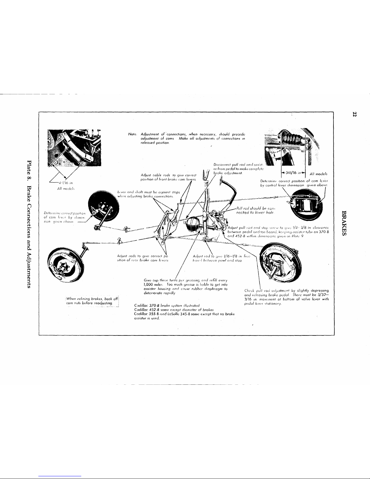
to
*0
rt
re
03
SB
**
re
O
0
3
3
re
o
rt
0
3
3
a
>
en
re
3
rt
s
w
CO
•When
relining brakes, back off
com
nuts before readjusting.
Give
cup
three turns
per
greasing
and
refill
every
1,000 miles. Too much
grease
is
liable
to get
info
assister housing and
cause rubber diaphragm
to
deteriorate
rapidly
Cadillac
370-B
brake
system illustrated
Cadillac
452-B
some except
diameter
of
brakes
Cadillac
355
Band
LaSalle
345-B
same
except
that
no
brake
ossisfer
is
used.
Check
pull
rod
adjustment
by
slightly
depressing
and releasing brake pedal There must
be 5/32—
3/)6
in.
movement
ot
bottom
of
valve lever
with
pedal lever stationary.
Page 93
BRAKES
23
General
Description
Caclillac-LaSalle
brakes are of the internal
type
with
two self-energizing shoes on each of the
four
brakes. The
floating
or upper brake shoes
are energized
with
the forward motion of the car.
For
this reason they do most of the braking and
are made of
alluminum
alloy.
The anchored or
lower
shoes are energized
with
the backward
movement of the car. Therefore, they do less
braking
and are made of steel.
The
aluminum
alloy
shoes naturally expand
more than the steel shoes under the
heat,
gener-
ated by the use of the brakes.
This
compen-
sates
for the tendency of the drums to expand
away
from
the shoes. The result is
that
Cadillac
brakes are just as effective toward the bottom
of a long
hill
as they are when first applied at
the top.
The
cam operating the shoes, is mounted on a
pivoted
bracket so as to be self-centralizing and
thereby compensate for unequal wear on the
brake
linings.
The
cam end of each brake shoe has a pivoted
link
which
rests
against the brake operating cam..
Thus,
instead of a
sliding
contact between the
cam
and the brake shoes,
there
is a
rolling
con-
tact between the cam and the pivoted
links.
This
construction
prevents wear on the cam and the
ends
of the brake shoes.
The
cam has a splined shaft on
which
is mounted
an
especially designed operating lever. The hub
of
this lever is broached to fit over the splined
shaft and is connected to the casing of the cam
lever
by an adjustable
link.
When
the nut on
the outer end of the
link
is turned, the hub turns
with
relation to the lever itself, thereby changing
the position of the brake operating cam.
This
construction
permits the simplest
known
method
of
brake adjustment.
The
front brakes are operated by a cable
extending
through the frame side bars to the
brake assembly on the wheels.
This
cable is
carried
in a reinforced,
flexible
casing or conduit,
and
is connected at the rear to a short
pull
rod
which
in turn is connected to a lever on the rocker
shaft.
The
foot pedal
operates
the brakes on four
wheels,
while
the hand brake lever
operates
the
rear brakes
only.
Thus
only
one set of shoes is
needed for both braking systems.
The
service operations and adjustments ol
the brakes are the same on all cars except the
370-B
and
452-B
cars. The
only
difference is
that
these
cars are equipped
with
a vacuum
brake assister.
VACUUM
BRAKE
ASSISTER
A
vacuum brake assister is used on the
370-B
and
452-B
cars. It is connected at the rear to
the center cross member of the frame, and at the
front
end to a lever on the pedal shaft and is
operated by vacuum
from
the intake manifolds.
The
force
thus
developed is applied to the lever
on
the pedal shaft, and is added to the force
applied
by the driver to the pedal.
Although
the
assister is connected to the brake pedal, it does
not interfere
with
the pedal action, and the foot
brakes can be applied whether the engine is
running
or not.
Also,
the assister does not affect
the adjustments of the brakes or any of the brake
connections up to the pedal.
The
control is positive, the valves being regu-
lated
by the movement of the pedal itself. The
assister develops power
only
while
the brake
pedal
is
moving
forward. As soon as the pedal
stops, the assister
ceases
to
build
up any lorce
and
merely helps to
hold
the position
which
has
been reached. The assister releases automatically
when
the pedal is released.
The
general design of the brake assister and the
various
stages
of its operation are shown on Page
26.
Service
Information
1.
Regrinding
Brake Drums
Cast-iron
brake drums supplied by the Parrs
Division,
lor
all
model cars
with
the shoe type brakes, arc finish-machined
at the Factory before being shipped.
This
eliminates the
necessity of finish-machining the drum alter
installing
it on
the wheel.
Careful
alignment of the drum on the hub,
however,
is of particular importance.
I
here
is a
limit
to the amount of metal
that
can
saicly
be removed
irom
a drum when regrinding. I he drums must
not be ground out more than .030
inch
over the
original
limit,
ol
the inside diameter.
When
brake drums are ux>
thin,
the excessive
heat
that,
frequently develops
will
cause them
to distort and warp
Also
the enlarged inner diameter ol the
drum
may prevent proper action of the cams.
Page 94
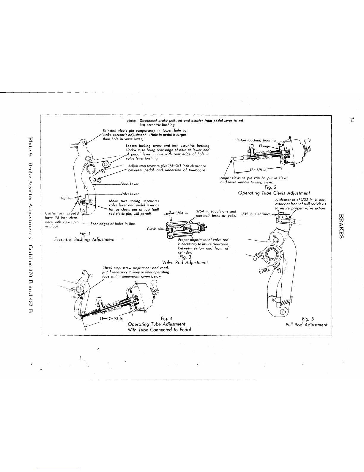
1/8
Coffer
pin should
have 1/8 inch
clear-
ance
with clevis pin
in place.
Note:
Disconnect brake pull
rod and
assister from pedal lever
to ad-
just eccentric bushing.
Reinstall
clevis pin temporarily in lower hole to
make eccentric adjustment.
(Hole
in
pedal is larger
thon
hole in valve leverj. p
)sfon
toucn;ng nouS(ng
^
loosen
locking screw
and
turn eccentric bushing
clockwise
to
bring rear edge
of
hole
at
lower
end
of
pedal lever
in
line
with
rear edge
of
hole
in
valve
lever
bushing.
Adjust stop screw
to
give
1/4—3/8
inch clearance
between pedal
and
underside
of
toe-board
Pedal Lever
Valve Lever
Adjust clevis
so pin can be put in clevis
and lever without turning
clevis.
Fig.
2
Operating Tube Clevis Adjustment
Mob
sure
spring separates
valve
lever
and
pedal lever
as
far
as
clevis
pin at top
(pull
rod
clevis
pin)
will
permit.
-3/64
Rear edges
of
holes
in
line.
Fig. 1
Eccentric
Bushing Adjustment
Clevis
pin
3/64 in.
equals
one and
one-half
turns
of
yoke.
1/32
in.
clearance
Proper adjustment
of
valve
rod
is necessary
to
insure
clearance
between
piston
and
front
of
cylinder.
Fig. 3
Valve Rod Adjustment
Check stop screw adjustment
and
read-
just
if
necessary
to
keep assister operating
tube within dimensions given
below:
Fig.
4
Operating Tube Adjustment
With
Tube Connected to Pedal
A
clearance
of
1/32
in. is
nec-
essary
at
front
of
pull
rod
clevis
to insure proper
valve
action.
Fig.
5
Pull Rod Adjusfmenf
Page 95
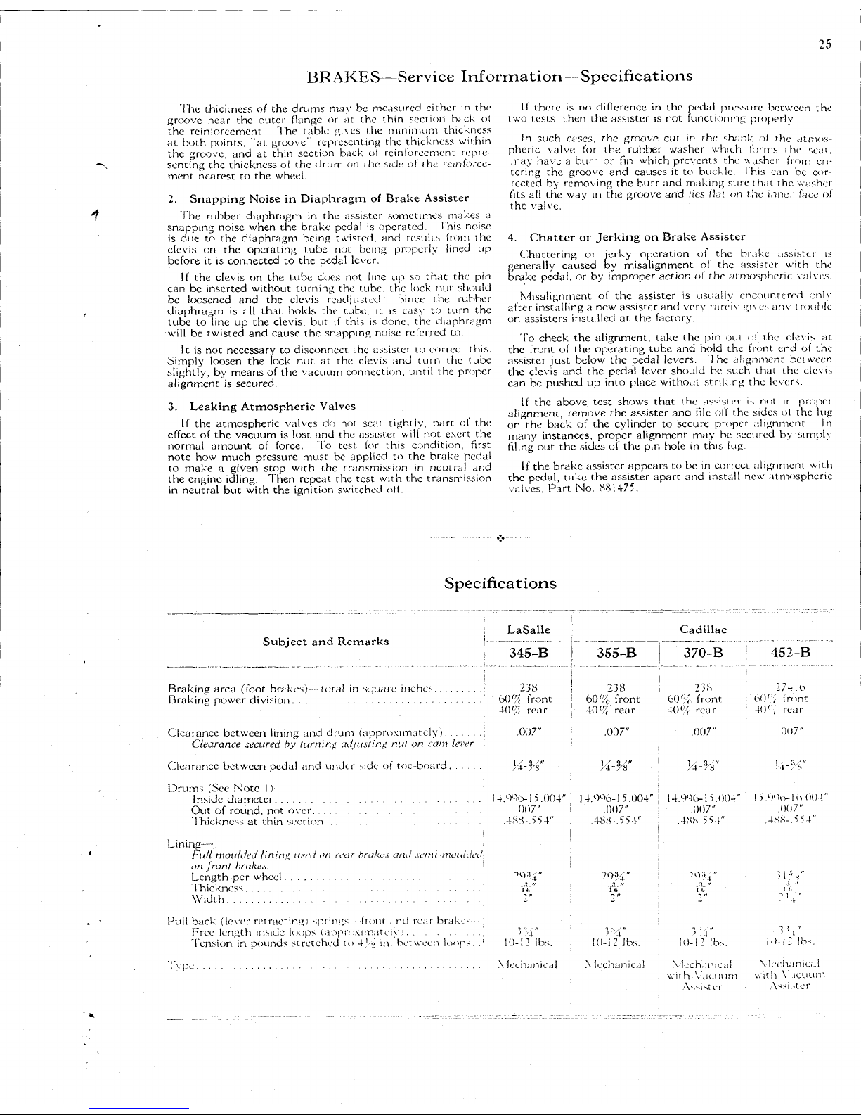
BRAKES—Service
Information—Specifications
25
The thickness of the drums may be measured cither in the
groove
near
the outer flange or at the thin section back ol
the reinforcement. The table gives the minimum thickness
at both points, "at groove" representing the thickness
within
the groove, and at thin section
Kick
ol rcinlorcemcnt repre-
senting the thickness of the drum on the side of the
reinforce-
ment
nearest
to the wheel.
2.
Snapping Noise in Diaphragm of Brake Assister
The rubber diaphragm in the assister sometimes makes a
snapping noise when the brake pedal is operated. This noise
is
due to the diaphragm being twisted, and results I rum the
clevis
on the operating
tube
not being properly
lined
up
before it is connected to the pedal lever.
If
the clevis on the rube docs not line up so
that
the pin
can
be inserted without turning the tube, the
lock
nut should
be loosened and the clevis readjusted. Since the rubber
diaphragm is all
that
holds the tube, it is easy to turn the
tube
to line up the
clevis,
but. if this is done, the diaphragm
will
be twisted and
cause
the snapping noise referred to.
It is not necessary to disconnect the assister to correct this.
Simply
loosen the
lock
nut at the clevis and turn the
tube
slightly,
by
means
of the vacuum connection,
until
the proper
alignment is secured.
3.
Leaking
Atmospheric
Valves
II the atmospheric valves do not
seat
tightly,
part,
ol the
effect of the vacuum is lost and the assister
will
not exert the
normal
amount of force. To
test
for this condition, first
note
how much
pressure
must, be applied to the brake pedal
to make a given stop
with
the transmission in neutral and
the engine
idling.
Then
repeat
the
test
with
the transmission
in
neutral but
with
the
ignition
switched off.
If
there
is no difference in the pedal
pressure
between the
two
tests,
then the assister is not functioning properly.
In
such cases, the groove cut in the shank of the atmos-
pheric valve for the rubber washer
which
forms the
seat,
may have a burr or fin
which
prevents the washer from en-
tering the groove and
causes
it to buckle. 1 his can be cor-
rected by removing the burr and making
sure
that
the washer
fits
all the way in the groove and lies flat on the inner lace ol
the valve.
4. Chatter or Jerking on Brake Assister
Chattering or jerky operation of the brake assister is
generally caused by misalignment of the assister
with
the
brake pedal, or by improper action of the atmospheric valves.
Misalignment
of the assister is usually encountered only
after installing a new assister and very rarely gives anv t rouble
on
assisters
installed at the factory.
To
check the alignment,
take
the pin out of the clevis at
the front of the operating
tube
and
hold
the front end of the
assister just below the pedal levers. I he alignment between
the clevis and the pedal lever should be such
that
the clevis
can
be pushed up into place without striking the levers.
If
the above
test
shows
that
the assisier is not in proper
alignment, remove the assister and
file
off the sides of the lug
on
the back of the cylinder to secure proper alignment. In
many instances, proper alignment may be secured by simply
filing
out the sides of the pin hole in this lug
If
the brake assister
appears
to be in correct alignment
with
the pedal,
take
the assister
apart
and
install
new atmospheric
valves.
Part No.
«81475.
Specifications
Subject and Remarks
LaSalle
345-B
355-B
Cadillac
370-B
452-B
Braking
area (foot brakes)—total in
square
inches.
Braking
power
division
Clearance between
lining
and drum (approximately)
Clearance
secured
by
turning
adjusting
nut on cam lever
Clearance between pedal and tinder side of toe-board
Drums
(See Note 1)—
Inside diameter
Out
of round, not over. . .
Thickness
at thin section.
238
60%
front
40%
rear
.007"
14.1)90-15.004"
.(107"
.4S8-.554"
238
60%
front
40%,'
rear
.007"
14.996-1 5.004"
.007"
.488-.554"
238
60%.
front
40%
rear
.007"
}4-H"
14.99(1-1
5,004"
.007"
.488-5 54"
274.o
b()% front
40";
rear
.007"
l5.99o-lo
004"
.007"
.488-.554"
Lining—
Full
moulded
lining
used
on rear brakes and
semi-moulded
on
Jront brakes.
Length
per wheel
Thickness
Width
Pull
back (lever retracting] springs -Iront and
rear
brakes -
Free length inside loops (approximately
Tension
in pounds stretched to 4'.> in. between loops. .
1
1 y pe .
29¾"
3¾"
10-12 lbs.
\
lechanical
29 -V,
3¾"
10-12 lbs.
X
lechanical
10-12 lbs.
Mechanical
with
Vacuum
Assister
31V
>
' i
10-12 lbs.
X
lechanical
with
Vacuum
Assizer
Page 96
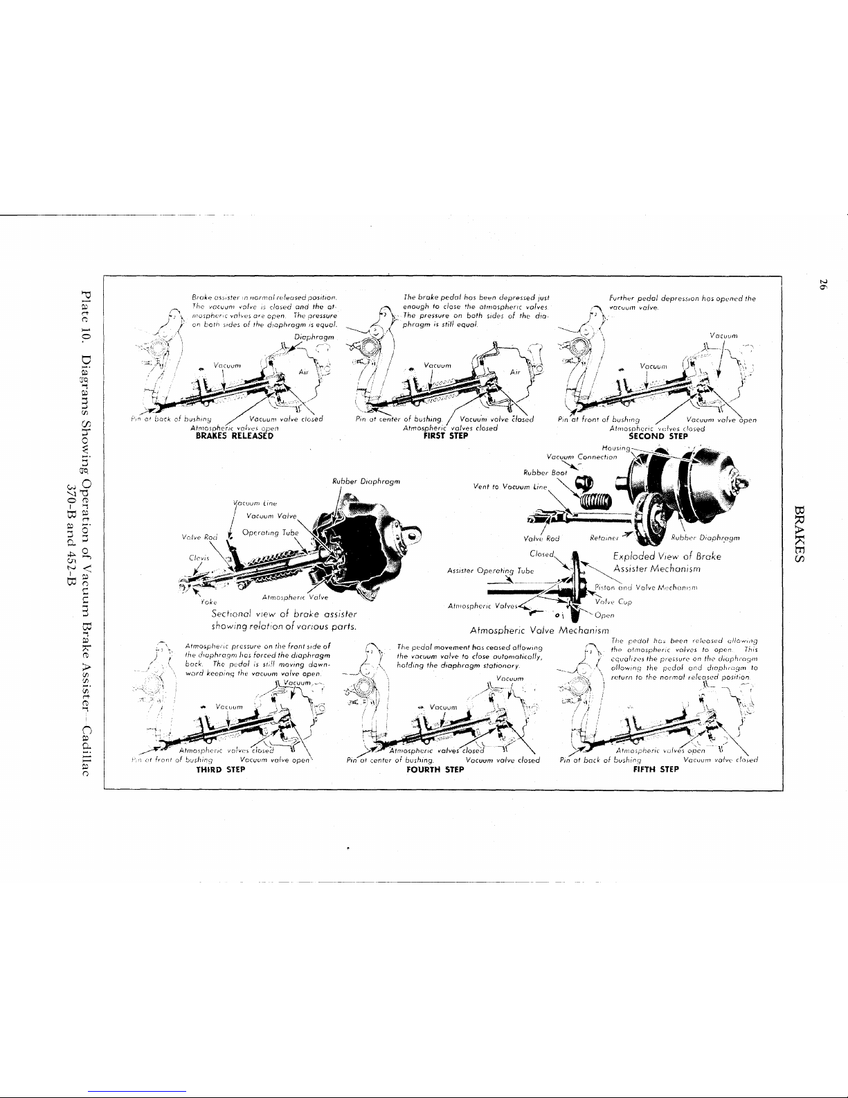
Broke assister
in
normal released position.
The vacuum valve
is
dosed
and the at-
mospheric
vofves are
open..
The
aressure
on both sides
of the
diaphragm
is
equal.
Diaphragm
The brake pedal
has
bean depressed just
enough
to
close
the
atmospheric valves
The pressure
on
both sides
of the
dia-
phragm
is
still
equal
a1 back
ol
bushing
Vacuum
valve closed
Atmospheric valves
open
BRAKES
RELEASED
Further pedal depression
has
opened
the
vacuum
valve.
Vacuum
\
center
of
bushing,
f Vacuum
Atmospheric valves closed
FIRST STEP
Rubber Diaphragm
Pin
at
front
of
bushing
Afmosohenc
valves
closed
SECOND STEP
Housing-
Vacuum Connection
Rubber Boot
Vacuum valve open
Vjocuum tine
Valve
Rod
Vent
to Vacuum
Line
\
ill®
Valve
Rod
Closed^
Retainc
laphragn
Assister
Operating Tube
*
Atmospheric
Vaive
Sectional
view
of
broke assister
showing relation
of
various
parts.
Atmospheric pressure
on the
front side
of
the diaphragm
has
forced
the
diaphragm
back.
The
pedal
is
still
moving
down-
ward
keeping
the
vacuum valve open.
\\ Vacuum,--.
Atmoipheetc vahes close6
\^
t
front
of
bushing Vacuum valve
open1*
THIRD STEP
Atmospheric Valves
Exploded View
of
Brake
Assister Mechanism
isfon
and Valve Mechonn-in
Valve
Cup
Open
Atmospheric
Valve
Mechanism
/
The pedal
movement
has
ceased
a/fowing
the vacuum valve
to
close automatically,
holding
the
diaphragm stationary.
Vacuum
.A
/
The
pedal
hai
been released allowing
the atmospheric valves
to
open. This
equalizes
the
pressure
on the
diaphragm
allowing
the
pedal
and
diaphragm
to
return
to the
normal released position
Atmospheric valves^closed
Pin
at
center
of
bushing. Vacuum valve closed
FOURTH
STEP
Atmospheric valves open
V>
Pin
at
back
of
buahing
Vacuum
valve closed
FIFTH
STEP
Page 97

BRAKES
27
Fig. I
Typical Front
Brake
Fig. 2
Typical
Rear
Brake
Cam
Lever
Fig. 3
Front
Brake
Adjustment
loosen
cam
bracket
locking
nut
and
apply
brakes
firmly to
centralize cam bracket. Tight-'
en nut before releasing brakes.
ck for equalization between right and
left,
turn down all four adjusting nuts
same
of turns until pedal travel is
approxi-
2-1/4
inches.
'1-1/6
turns equals 1
pedal
travel).
If equalization is not O.K., first turn down nuts
until all four brakes just drag; then back off
nuts same number of turns to give proper
pedal
travel.
Recheck for equalization and
make further adjustment if necessary.
Cam
Lever
Fig. 4
Rear
Brake
Adjustment
•Adjusting
Nut
Fig. 5
Cam Lever
With
Half of Casing Removed
Plate
11.
Brake
Details
and
Adjustments
Page 98

2
rt
P
era
O
5
05
CD
3*
H=
0
8
1
at
TO
£°
on
>-s
p
rt
0
0
)-1¾
n
r
p
p
r—'
Ol
P
I o
C
C
3
w
p
rt
>
CO
co
rt
Broke
assister in normal released position. The
}
vacuum
and atmospheric
valve
is
a//
Hie
way
forward
uncovering
fhe
poisoge
in
the operating lube and
opening the front chamber to Ihe intake
vacuum
tine
Vacuum line
the brolce pedal
hast been depressed
;'usl
\enough
for Ihe
valve
to
close
the
passage
between
the
fronl
and rear chambers.
The assister cannot
function
as
the
fronl
chamber
is no! yet
open
to
the
I
atmosphere
Passage Open
fo
Rear
Chamber
Pin
at
Back
Bushing
Rod
BRAKES
RELEASED
Air
Passage
Further pedal movement has
moved
the
valve
^baci
far enough to uncover again the passage in the
operating tube
keeping
dosed the passage between
the two chambers, and thus opening the front chamber
\
to
fhe atmosphere
Vacuum
Pin
af
Fronf
FIRST
STEP
rung
SECOND
STEP
Vacuum
Front Chamber
Air
Passage I Vacuum Line
Vacuum
and
A'tr Passage
Valve Rod —' Rubber Soot
Operating Tube
•*
^tiair Piston
^Rear
Chamber
Sectional
view
of
brake assister showing relation of various parts
Atmospheric pressure in the front
chamber
is
/
forcing the piston bock as indicated by the large
arrow.
The pedal
is
still
moving
downward so as to keep the
\
valve
back,
leaving the atmospheric passage open
Ihe pedai movement has
ceased,
allowing the
valve
to close the atmospheric passage automatically.
As the air m the front chamber
cannot
escape,
it
pre-
vents the piston
from
moving
forward and keeps the
I
piston
in
the position fust reached
Vacuum
Valve Spring
•
Valve
Vacuum
and
Atmospheric Valve Mechanism
The
pedol
has
been
released, permitting the
valve
to
return
to
its
forward
portion
opening
fhe
passage
between
the
two
chambers.
This
equalizes
the vacuum pressure on both sides
of
the piston allow
|
ing the piston and pedal
to
return
to the
norma)
re-
'
teased
positions
Passage Ogenjo
Rear
Chamber-
THIRD
STEP
FOURTH
STEP
Vacuum
Pin
ai
Back
of
Bushing
FIFTH
STEP
Vacuum
>
Page 99

27B
BRAKES—General
Description—Service
Information
General
Description
The brakes on the "C" series cars are the
same
as on the corresponding "B" cars
with
the ex-
ception
that
a brake assister is used on the
Cadillac
355-C
and the
LaSalle
345-C.
A
coil
spring also surrounds each brake drum
on
all "C" cars to give additional
cooling
surface
and to absorb any noise produced by vibration in
the drum.
Because of a difference in the length of the
operating tube, the 355-C assister unit is not interchangeable
with
that
used on the 345-C.
Aside
from the brake assister on the 355-C and
345-C
cars, all adjustments of the brakes and
brake connections remain the
same
as on the 'B"
cars.
Service
Information
5. Lubrication of Brake
Assister
Early
V-12 and V-16 cars are
provided
with
a ratchet type
grease cup for
lubricating
the brake assister.
With
this
ratchet type grease cup,
lubrication
is necessary every 1000
miles.
To
lubricate the assister,
simply
fill
the grease cup
with
•light
cup grease
(G-2|^)
and turn
down
a few turns every 1000
miles.
It is extremely important that the G-2J-3 cup grease
be used during
cold
weather.
When
wheel bearing lubricant
is
used at this point,
difficulty
is sometimes experienced in
extremely
cold
weather
with
the lubricant hardening and
interfering
with
the smooth operation of the assister.
Later
cars are equipped
with a wick
oiler
for
lubricating
the
brake assister.
With
this type
oiler
the
lubrication
require-
ments are different, an engine oil of S. A. E.
viscosity
20 being
required
every 6000
miles.
This
new type
wick
oiler,
part No. 885268 can be used on
any
370 and 452 brake assister. To
install,
simply
remove
the grease cup and screw the
oiler
in place, tightening the hex
securely.
The brake assister
pull
rod should be removed and
cleaned
of all the old grease.
After
reassembling, the
oiler
reservoir
should be
filled
with
S. A. E. 20 engine oil and
screwed
in place.
Lubrication
is then required
only
on the
regular
number 6 and 12
lubrication
operations.
The
brake assister on the
345-C
and
355-C
cars requires the
same
lubrication
as the
clutch
power
cylinder
on the "B"
models.
That is, one ounce of S. A. E. No. 10 oil or
light
machine
oil of weight
similar
to shock absorber oil should be
injected
in the front chamber of the
cylinder
through the
plugged
opening in the
cylinder
head every 6000
miles.
To
Intake Manifold
Piston
touching
housing
at front side
'
Pedal
Lever
. . , .
\
Asstster
Unit
'Valve
Rod
l
Remove
pfug
to
lubricate
cylinder
^Ad\ust
valve
rod by
turning
cfavis
out
against
pin
(use
straight
pin)and
then
backing
off
1-)/2
turns
Fig.
1
Brake Assister Connections
Operating
Tube Adjustment
Plate
11B. Brake
Assister
Adjustments—Cadillac
355-C—LaSalle
345-C
August
I'm
Page 100

28
CLUTCH
Ventilator
Release
tever.
Release Bearing.
Starter
Ring
Gear
~Flywheel
Spring
Pressure
-
Plate
Driving
Pin
Driving
Plates
Clutch
Connection
Spring
Pressure
Plate
Driving pins
are
press
fit in
center
plate;
free
sliding
fit in
front
and
rear plates.
Release Studs
for
Front Driving
Plate
Release
Leva
Pivot
Bolt
Clutch
Hub
Driven
Discs
Front Driving
Plate
Clutch
Spring
(12
used!
'
Fig.
1
Sectional View
of
Cadillac 355-B Clutch
and
Flywheel.
Typical
of ail
models.
Rear Driving
Plate-
Center Driving
Plate
Fig. 2
Clutch
Disassembled
Do
not
touch these Starter Ring Gear
on
nuts
to
remove
or
Center ^Driving
Plate
disassemk
Driving
Pin
Cadillac
452-B
Double
Release Lever
Cadillac
355-6, 370-8-
La
Salle
345-B
pjg 3
Rear
view
of
clutch showing double-lever release
mechanism.
^Release finger yoke bolt
to spring pressure plate
Release Lever
Pivot
Bolt
Release
Stud;
for
Front
Driving Plate
Release
Lever Pivot Bolt
Fig.
4
View
of
Clutch
Release
Mechanism
Inner
Release Lever
Hole
in
inner lever
is
larger than
pin to
compensate
for
springing
or
variation
in
parts.
F<g-
5
Clufch
Release
Lever
Assembly
Plate
12.
Clutch
Details
 Loading...