

Page 1
CADILLAC
OPERATOR'S
MANUAL
FILE
COPY
DO
mr
REMOVE
&
^
liMTlON NO. 370-1
lit mitring </ duplicate »/ this Mtinmil, specif} the
above number or the engine number oj the c?r.
Page 2
Table
of
Contents
CHAPTER
\--Cadillac
Service
'
Cadillac-La Salle Service Stations—Service card—Service contractService charges—Repair parts—The owner's obligation- Lubrication—
Inspection.
CiiAFrER
II—Operation
8 1
Locks—Ignition switch lock—Gasoline gauge—Throttle control
- '
Carburetor choke control—Spark control—Starter pedal-
Oil
pressure
gauge—Ammetei—Clutch pedal—Transmission control -Coasting
Brakes—Lighting switch- -Danger
of
running engine
in
closed garage.
CHAPTER
311—Equipment 21
Windshield
and
ventilation- Windshield cleaner Adjustable seats
Cigar lighters—Tools—TIKES—Inllation pressure- Spare wheel carrier
—Spare tire carrier—Use
of
jack
in
changing tires—Changing tires
-
Tire balancing marks.
CHAPTER
IV—Lubrication 29
Lubrication schedule—Lubrication Notice—Lubrication chart-
LUBRICANTS— Engine oil — Gear lubricant — Chassis grease—Wheel
bearing grease—Water pump grease—ENGINE LUBRICATION—Oil
I
level—Crankcase ventilating system and oil filter—Replacing engine oil.
,
CHAPTER
V—Cold
Weather Operation
36 S
PREPARING
FOR
COLD WEATHER—Anti-freezing solutions
j
Capacity
ol
cooling system—Winter lubrication-Storage battery-
Gasoline system—STARTING
THE
ENGINE—Choke button
-
Priming
the
carburetor—Position
of
throttle hand lever—Position of
spark control—Use
of
starter—Use
of
accelerator before engine is warm.
CHAPTER
VI—
General
Care
43
Storage battery—Cooling system—Gasoline filter—Temporary brake
adjustment—BODY—Care
of
finish—Care
of the
top—Cleaning
up-
holstery—Door hardware.
CHAPTER
VII—Storing Car 49 j
Engine—Storage battery—Tires—Body
and
top—Taking
car out of ,
storage.
[
CHAPTER
VIII—Specifications
and
License Data
. . • ^ i
W
CHAPTER
lbQ m,t- £.
CADILLAC
SERVICE
HPHE
owner
of a
Cadillac
car has
purchased
not
simply a line
1
piece
of
machinery, ingeniously designed
and
carefully
built—he
has
purchased a pleasant
and
dependable mode
of
transportation.
The
car
itself
is
only
one
factor
in
securing this
transportation—the
other factor
is
Cadillac Service, which
is
built
upon a standard policy, clearly defined
to the car
owner
and
guaranteeing
him
efficient
service everywhere
at
standard prices under
factory
regulation.
Cadillac-La
Salle Service Stations
Cadillac
Service extends wherever Cadillac
and
La Salle cars
are
sold. Service stations
conducted
by
Cadillac distrib-
utors
and
dealers
are
designa-
ted
as
"Authorized Cadillac-
La
Salle Service Stations"
and
are
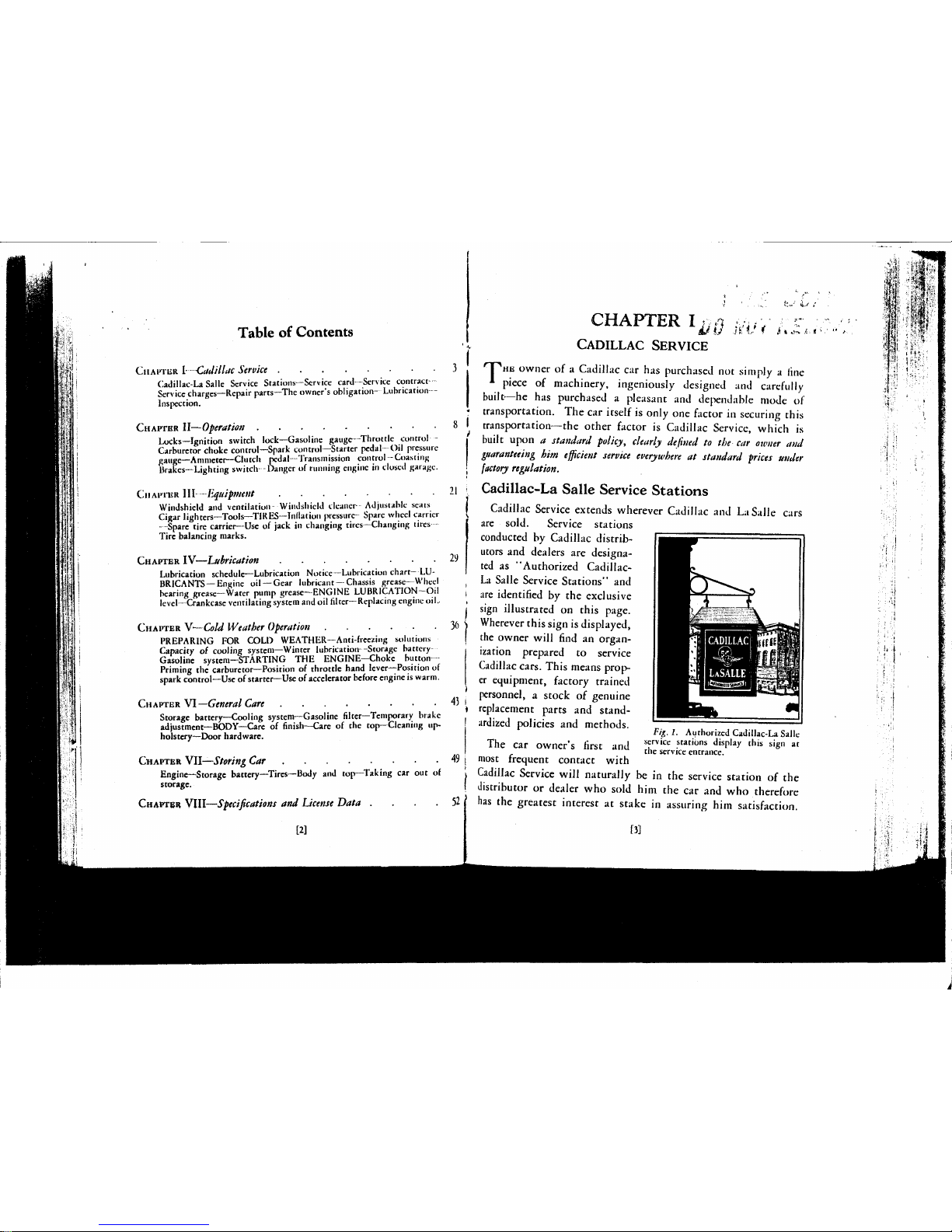
identified
by the
exclusive
sign
illustrated
on
this page.
Wherever
this sign is displayed,
the
owner will find
an
organ-
ization
prepared
to
service
Cadillac
cars. This means prop-
er
equipment, factory trained
personnel, a stock
of
genuine
replacement
parts
and
stand-
ardized
policies
and
methods. c- , , k • ,^ ,„ , o ,.
1
rig. 1.
Authorized Cadillac-La Salle
The
car
owner's first
and sf
rvicc .statibns display this sign
at
iiic
t,di
uwnci » nisi
aim the
service entrance.
most
frequent contact with
Cadillac
Service will naturally
be in the
service station
of the
distributor
or
dealer
who
sold
him the car and who
therefore
has
the
greatest interest
at
stake
in
assuring
him
satisfaction.
[3]
Page 3
CADILLAC SERVICE CARD
Th4*i.te«.r<lfy that
Mr. Joseph Brow
Nevertheless,
he
may
feel perfectly free
to
use
his car for
ex-
tended travel without depriving himself
of
the
service benefits
to which
he is
entitled
at
his
local service station.
He
will find
other Authorized Cadillac-La Salle Service Stations able
and
willing
to
render
the
same service.
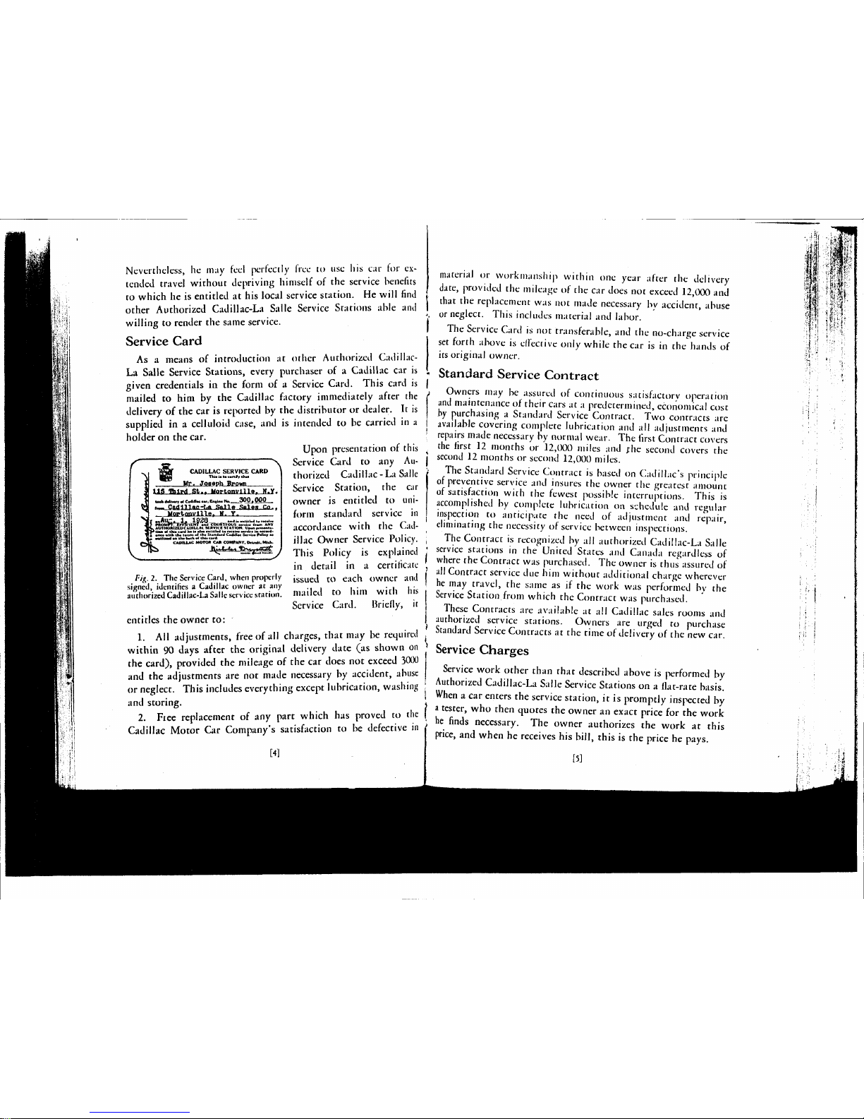
Service Card
As a means
of
introduction
at
other Authorized Cadillac-
La Salle Service Stations, every purchaser
of a
Cadillac
car
is
given credentials
in
the
form
of a
Service Card. This card
is
mailed
to
him
by the
Cadillac factory immediately after
the
delivery
of the car is
reported
by the
distributor
or
dealer.
It is
supplied
in a
celluloid case,
and
is
intended
to
be
carried
in a
holder
on the car.
Upon presentation
of
this
Service Card
to any Au-
thorized Cadillac
- La
Salle
Service Station,
the car
owner
is
entitled
to
uni-
form standard service
in
accordance with
the
Cadillac Owner Service Policy.
This Policy
is
explained
in detail
in a
certificate
issued
to
each owner
and
mailed
to him
with
his
Service Card. Briefly,
it
entitles
the
owner
to:
1.
All
adjustments, free
of all
charges, that
may
be
required
within
90
days after
the
original delivery date
(as
shown
on
the card), provided
the
mileage
of
the car
does
not
exceed 3000
and
the
adjustments
are not
made necessary
by
accident, abuse
or neglect. This includes everything except lubrication, washing
and storing.
2.
Fiee replacement
of
any
part which
has
proved
to the
Cadillac Motor
Car
Company's satisfaction
to be
defective
in
[41
ta*fc
Mwy
id
Cadillac
«ar,
EntlM No.__300j QQQ ...
i~_.CedlUaarLA_SaHe.Sales
Co-*
.. Mortonville,
N.
Y.
sfe »i,Altl« 1. XQfSQ _ andiaaniiikd tarantna
if f*OMPT7TmCli:Nf
an
d
COURTfOUS «r.i« (torn ANV
JV AOTHORUEDCAOtLLACSeUVKtSTATIOft. VnMpr.i~.i9TP tte> af tfcta card ha •• ••» •milled to racain rank* it. ward«1 aixa -Ilk th*
I*TH»
"I itw Standard Cadillac Sw.i»
FBIM*
aa
*' ' - 1 an tha
fcack
«( thU card.
CADILLAC MOTOR CAR COMPANY, Onraii. Mid..
ML
Fig.
2.
Tlic Service Card, when properly
signed, identifies a Cadillac owner
at
any
authorized Cadillac-La Salle service station.
material
or
work mans hip within
one
year after
the
delivery
date,
provided
the
mileage
of
the car
does
not
exceed 12,000
and
that
the
replacement
was not
made necessary
by
accident, abuse
or neglect. This includes material
and
labor.
The Service Card
is
not
transferable,
and the
no-charge service
set forth above
is
effective only while
the car
is in
the
hands
of
its original owner.
Standard Service Contract
Owners
may
be
assured
of
continuous satisfactory operation
and maintenance
of
their cars
at a predetermined, economical cost
by purchasing a Standard Service Contract.
Two
contracts
are
available covering complete lubrication
and
all
adjustments
and
repairs made necessary
by
normal wear.
The
first Contract covers
the first
12
months
or
12,000 miles
and the
second covers
the
second
12
months
or
second 12,000 miles.
The Standard Service Contract
is
based
on
Cadillac's principle
of preventive service
and
insures
the
owner
the
greatest amount
of satisfaction with
rhe
fewest possible interruptions. This
is
accomplished
by
complete lubrication
on
schedule
and
regular
inspection
to
anticipate
the
need
of
adjustment
and
repair,
eliminating
the
necessity
of
service between inspections.
The Contract
is
recognized
by all
authorized Cadillac-La Salle
service stations
in the
United States
and
Canada regardless
of
where
the
Contract
was
purchased.
The
owner
is
thus assured
of
all Contract service
due him
without additional charge wherever
he
may
travel,
the
same
as if
the
work
was
performed
by the
Service Station from which
the
Contract
was
purchased.
These Contracts
are
available
at all
Cadillac sales rooms
and
authorized service stations. Owners
are
urged
to
purchase
Standard Service Contracts
at
the
time
of
delivery
of
the new car.
Service Charges
Service work other than that described above
is
performed
by
Authorized Cadillac-La Salle Service Stations
on a flat-rate basis.
When a car
enters
the
service station,
it
is
promptly inspected
by
a tester,
who
then quotes
the
owner
an
exact price
for the
work
he finds necessary.
The
owner authorizes
the
work
at
this
price,
and
when
he
receives
his
bill, this
is the
price
he
pays.
[5]
Page 4
Charges prevailing at Authorized Cadillac-La Salle Service
, .» Sta£jrpn$ are based on standard schedules furnished by the Cadillac
S'^y « Motor Car Company. These schedules call for methods and
tools approved by the same engineers who designed and built
the car, assuring the highest quality of work at the lowest
possible price. Standard Price Schedules are open to inspection
by owners at any Authorized Cadillac-La Salle Service Station.
Repair Parts
Genuine Cadillac parts, manufactured to the same rigid
specifications as the parts entering into the original assembly of
the car, are carried in stock by Authorized Cadillac-La Salle
Service Stations. They are sold at uniform prices throughout
the United States, and are not subject to the addition of hand-
ling, excise or other supplementary charges. Printed price lists,
published by the Cadillac Motor Car Company, are open to
inspection by owners at any authorized Cadillac distributor's
or dealer's establishment.
The Owner's Obligation
All of these service facilities are placed at the disposal of the
Cadillac owner, in order that his car may be a continuous source
of satisfaction and utility. This result cannot be guaranteed,
however, unless the owner fulfills certain definite obligations
himself,
as follows:
1.
To drive the car at moderate speeds for the first 500 miles.
2.
To operate the car in accordance with the instructions
contained in this manual.
3.
To check the engine oil level every 100 to 150 miles, and
add oil as often as necessary to keep the indicator at "full."
4.
To check the tire pressure at least every week, and keep
it up to the recommended pressure—40 pounds in front and rearon cars driven at high speeds, 45 pounds in front.
5.
To add distilled water to the storage battery every 1000
[6]
miles,
and in warm weather every 500 miles, or at least every
two weeks.
6. To have the car lubricated every 1000 miles, or once a
v month, in accordance with the lubrication schedule on page 28.
I 7. To take the car to an Authorized Service Station for
inspection every 1000 miles, or at least once a month.
Lubrication
<
I The first five items above are details which do not necessarily
) warrant a visit to the service station. For lubrication, however,
the owner is urged to patronize Authorized Cadillac-La Salle
I Service Stations, because they are prepared to furnish this service
• in a manner that cannot be duplicated elsewhere. Only approved
lubricants are used, the specifications of which have been worked
j out by Cadillac engineers to give the best possible results.
Workmen who specialize on Cadillac cars know exactly where
lubrication points are located and how much lubricant to apply.
The charge for this lubrication service is only about half a cent
a mile, which includes the cost of the lubricants.
Inspection
Preventive service is a fundamental principle of Cadillac
' Service. "Preventive service" is the practice of inspecting the
car at regular intervals and making those adjustments that need
attention before the need becomes an emergency. Inspections
should be made every 1000 miles, in order to insure transportation satisfaction. Authorized Cadillac-La Salle Service Stations
( will make such inspections without charge, provided no disI mantling of units is necessary.
| The Cadillac owner is urged to take full advantage of this,
not only while the car is new, but throughout its entire life.
i Preventive service rendered every 1,000 miles or once
i a month by an Authorized Cadillac-La Salle Service
| Station, is the surest guarantee of long life and com' plete motoring satisfaction at the least possible
expense.
W
Page 5
CHAPTER II
OPERATION
O
NE
of the first things the driver of a new car should do is
to familiarize himself with the various controls described
in the following chapter.
Locks
Each car is equipped with two each of two different keys.
The handles of one set of keys are hexagonal in shape: these
keys unlock the combination ignition switch and transmission
lock, the lock on the front door, the spare wheel carrier and thfe
battery box. The keys in the other set have oval handles: these
keys unlock the rear doors of chauffeur driven cars, the rear decks
of roadsters and coupes, and the various package compartments.
The lock number is stamped on each key, but not upon the
face of the lock. The owner should make a record of the key
numbers as soon as he takes delivery of his car, so that in the
event both keys are lost, a duplicate key can easily be obtained
from a Cadillac distributor or dealer.
The right front door can be locked from the inside to prevent
intruders from forcing their way into the car. This can be
accomplished simply by turning the key to the locked position
on the outside before entering the car. The door will then be
locked from the outside, although it can be opened from the
inside in the usual manner.
Ignition Switch
Lock
The lock in the center of the instrument panel controls both
the ignition switch and the transmission lock. When the key
is turned, the cylinder of the lock will slide out about half an
[8]
inch, turning on the ignition and unlocking the transmission
by means of a cable connection to the shifter shafts. To shut
off the ignition and lock the transmission, turn the key to the
locked position and push the lock cylinder all the way in. The
car can be locked when the transmission is in neutral or in reverse.
Do not attempt to shut off" the ignition when the transmission is
in any forward gear. Be sure to remove the key before leaving
the car.
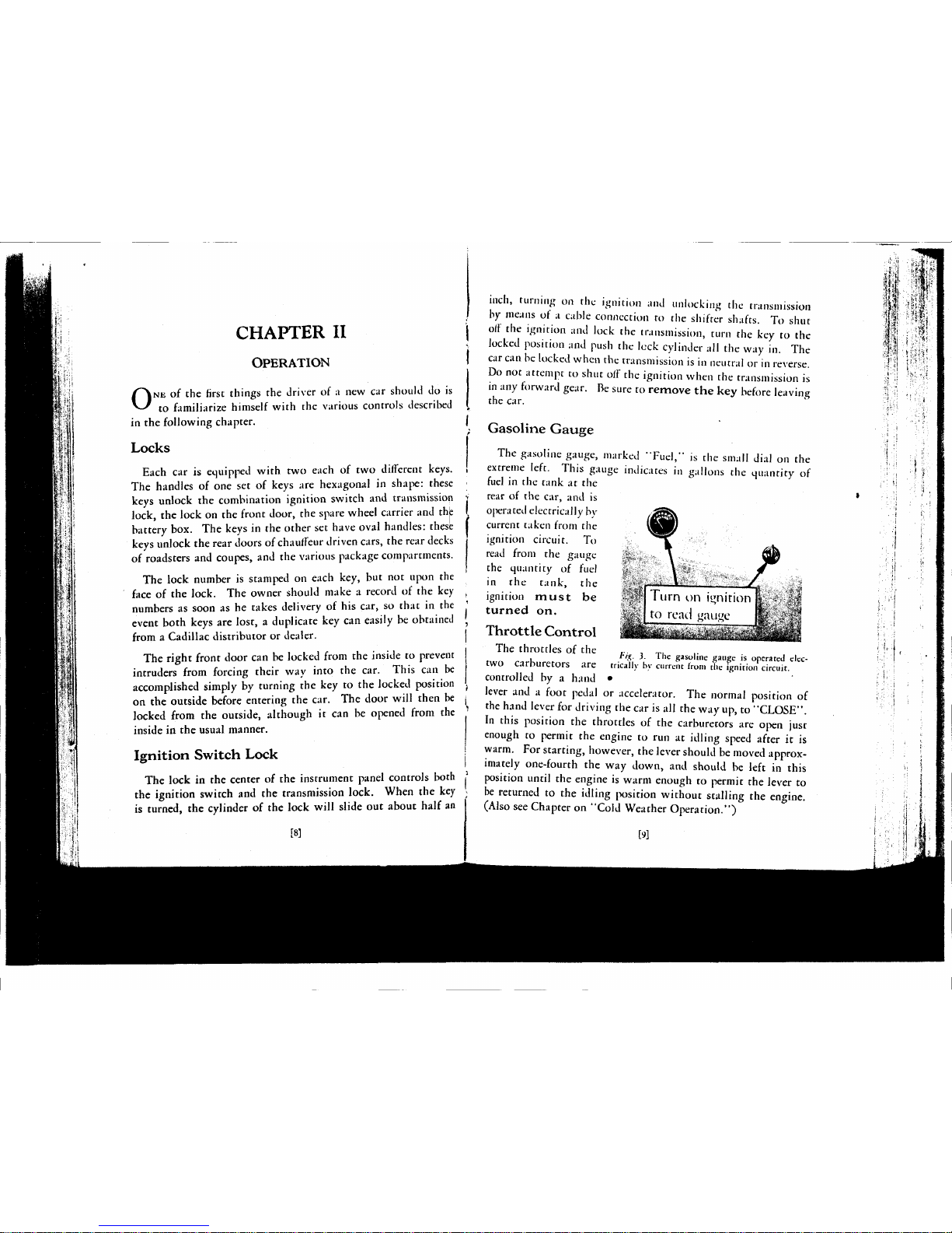
Gasoline
Gauge
The gasoline gauge, marked "Fuel," is the small dial on the
extreme left. This gauge indicates in gallons the quantity of
fuel in the tank at the
rear of the car, and is
operated electrically by
current taken from the
ignition circuit. To
read from the gauge
the quantity of fuel
in the tank, the
ignition must be
turned
on.
Throttle
Control
The throttles of the
two carburetors are
controlled by a hand •
lever and a foot pedal or accelerator. The normal position of
the hand lever for driving the car is all the way up, to "CLOSE".
In this position the throttles of the carburetors are open just
enough to permit the engine to run at idling speed after it is
warm. For starting, however, the lever should be moved approximately one-fourth the way down, and should be left in this
position until the engine is warm enough to permit the lever to
be returned to the idling position without stalling the engine.
(Also see Chapter on "Cold Weather Operation.")
^ iw>iminhi
Turn on i«nirion
to re;ul "au^e
/7¾.
3. The gasoline gauge is operated elec-
trically by current iron) the ignition circuit.
M
Page 6
Carburetor Choke Control
Correct use of the choke control is essential not only to quick
starting of the engine, but also to the life of the engine. The
button must be pulled our far enough in starting to provide an
explosive mixture quickly so that the battery is not unnecessarily discharged by useless cranking. The button must also be
left out far enough during the warming-up period so that the
engine will run without missing and "popping back."
On the other hand, it should not be pulled out any further or
left out any longer than is necessary to accomplish these results,
because some of the excess liquid gasoline in the enriched mixture
does not burn and may wash off the oil on the cylinder walls,
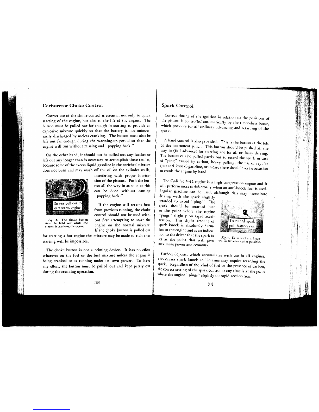
interfering with proper lubrication of the pistons. Push the button all the way in as soon as this
can be done without causing
"popping back."
If the engine still retains heat
from previous running, the choke
control should not be used with-
Fig. 4. The choke button out first attempting to start the
must be held out while the . , .
starter is cranking the engine. engme on the normal mixture.
If the choke button is pulled out
for starting a hot engine the mixture may be made so rich that
starting will be impossible.
The choke button is not a priming device. It has no effect
whatever on the fuel or the fuel mixture unless the engine is
being cranked or is running under its own power. To have
any effect, the button must be pulled out and kept partly out
during the cranking operation.
[10]
Spark Control
Correct timing of the ignition in relation to the positions of
the pistons is controlled automatically by the timer-distributor,
which provides for all ordinary advancing and retarding of the
spark.
A hand control is also provided. This is the button at the left
on the instrument panel. This button should be pushed all the
way in (full advance) for starting and for all ordinary driving.
The button can be pulled partly out to retard the spark in case
of "ping" caused by carbon, heavy pulling, the use of regular
(not anti-knock) gasoline, or in case there should ever be occasion
to crank the engine by hand.
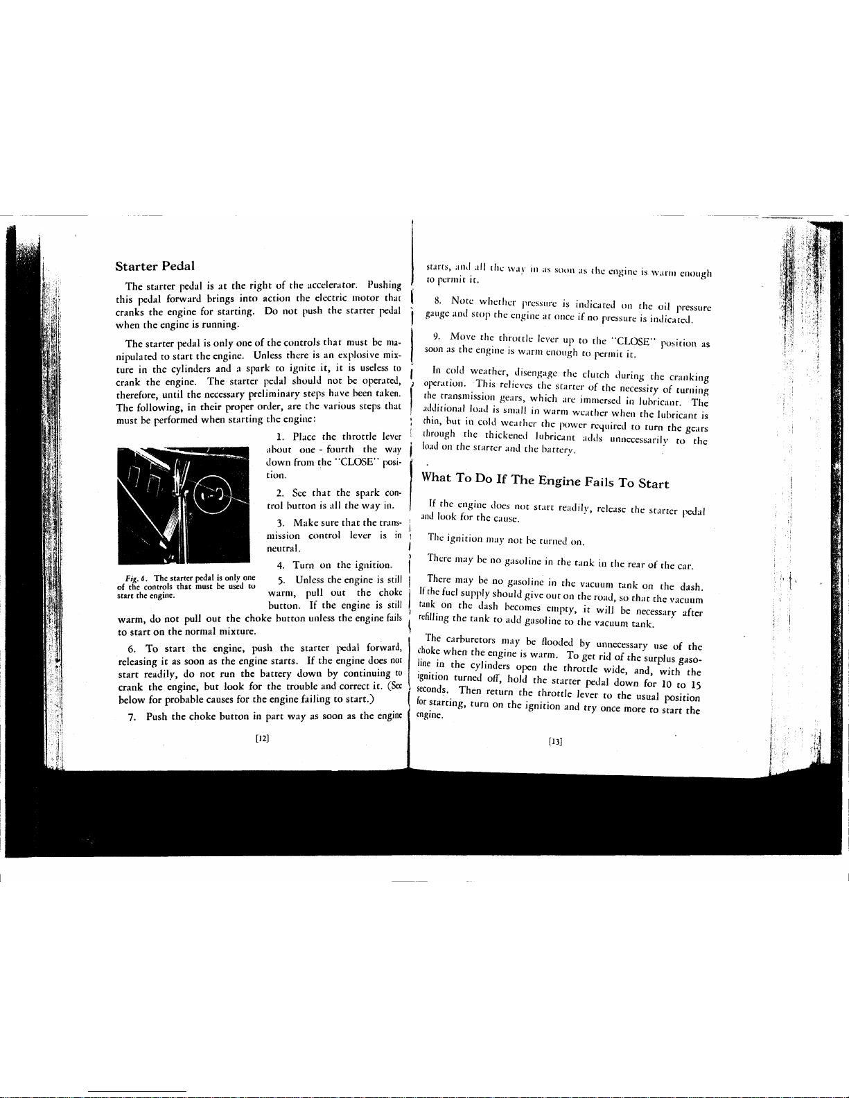
The Cadillac V-12 engine is a high compression engine and it
will perform most satisfactorily when an anti-knock fuel is used.
Regular gasoline can be used, although this may necessitate
driving with the spark slightly
retarded to avoid "ping." The -v ,/
spark should be retarded just i
'••
__^ \
to the point where the engine
"'pings"
slightly on rapid acceleration. This slight amount of
spark knock is absolutely harmless to the engine and is an indication to the driver that the spark is
F>g y Drjve wjth spark con
.
set at the point that will give trol as far advanced as possible.
maximum power and economy. :
Carbon deposit, which accumulates with use in all engines,
also causes spark knock and in time may require retarding the
spark. Regardless of the kind of fuel or the presence of carbon,
the correct setting of the spark control at any time is at the point
where the engine "pings" slightly on rapid acceleration.
["I
Page 7
Starter Pedal
The starter pedal is at the right of the accelerator. Pushing
this pedal forward brings into action the electric motor that
cranks the engine for starting. Do not push the starter pedal
when the engine is running.
The starter pedal is only one of the controls that must be manipulated to start the engine. Unless there is an explosive mix-
ture in the cylinders and a spark to ignite it, it is useless to
crank the engine. The starter pedal should not be operated,
therefore, until the necessary preliminary steps have been taken.
The following, in their proper order, are the various steps that
must be performed when starting the engine:
1.
Place the throttle lever
about one - fourth the way
down from the "CLOSE" position.
2.
See that the spark con-
trol button is all the way in.
3.
Make sure that the transmission control lever is in
neutral.
4.
Turn on the ignition.
F/£. «. The starter pedal is only one 5 Unless the engine is Still
of the controls that must be used to °
start the engine. warm, pull out the choke
button. If the engine is still
warm, do not pull out the choke button unless the engine fails
to start on the normal mixture.
6. To start the engine, push the starter pedal forward,
releasing it as soon as the engine starts. If the engine does not
start readily, do not run the battery down by continuing to
crank the engine, but look for the trouble and correct it. (See
below for probable causes for the engine failing to start.)
7.
Push the choke button in part way as soon as the engine
[12]
stairs,
and all the wav 111 as soon as the engine is warm enough
to permit it.
8. Note whether pressure is indicated on the oil pressure
gauge ami stop the engine at once if no pressure is indicated.
9. Move the throttle lever up to the "CLOSE" position as
soon as the engine is warm enough to permit it.
In cold weather, disengage the clutch during the cranking
; operation. This relieves the starter of the necessity of turning
I the transmission gears, which are immersed in lubricant. The
J additional load is small in warm weather when the lubricant is
j thin, but in cold weather the power required to turn the gears
j through the thickened lubricant adds unnecessarily to the
j load on the starter and the battery.
What To Do If The Engine Fails To Start
If the engine does not start readily, release the starter pedal
and look for the cause.
1
i
' The ignition may not be turned on.
There may be no gasoline in the tank in the rear of the car.
There may be no gasoline in the vacuum tank on the dash.
If the fuel supply should give out on the road, so that the vacuum
tank on the dash becomes empty, it will be necessary after
refilling the tank to add gasoline to the vacuum tank.
The carburetors may be flooded by unnecessary use of the
choke when the engine is warm. To get rid of the surplus gasoline in the cylinders open the throttle wide, and, with the
ignition turned off, hold the starter pedal down for 10 to 15
> seconds. Then return the throttle lever to the usual position
I for starting, turn on the ignition and try once more to start the
I engine.
[13]
Page 8
Oil Pressure Gauge
The small dial at the left of the
clock is the oil pressure gauge.
This gauge does not indicate the
quantity of oil in the engine. It
indicates only the
pressure
under
which the oil is forced to the
engine bearings.
Fig.7. The oil gauge does not
indicate ijuantity; it only shows
the pressure under which oil is
forced to the engine bearings.
I
When the engine is not running,
the pointer on the oil pressure
gauge should remain at zero, but
as soon as the engine is started and as long as it runs, the gauge
should show pressure. If no pressure is indicated when the
engine is running, stop the engine at once and determine the 1
cause. Serious damage may be done if the engine is run without
oil pressure.
Ammeter
The ammeter shows how much current the generator is furnishing the battery when the motor is running and how much the
lights and ignition are drawing from the battery when the generator is not charging. It does not register the current drawn by
the starting motor when starting the engine nor the total output
of the generator when the lights
are on.
The ammeter should indicate ,
on the "Charge" side most of '
the time, otherwise, more current
will be taken out of the battery
than is put into it and the battery
will eventually become fully dis-
charged, j
Fi%.
S.
The ammeter indicates
the amount of electrical current
flowing to or from the battery.
are in use, the ammeter should show "Charge" as soon as the
car is running ten or twelve miles per hour in high gear. If
the ammeter should show "Discharge" with all lights off,
either when the engine is not running or when the car is running
more than twelve miles per hour, the cause should be investigated.
Clutch Pedal
The clutch has two uses: First, to enable the car to be started
gradually and without jerk or jar; second, to permit shifting of
the transmission gears. The operation of the clutch is discussed
below in connection with the transmission control. Further
comment is unnecessary at this point, except the following sug-
gestions to the driver:
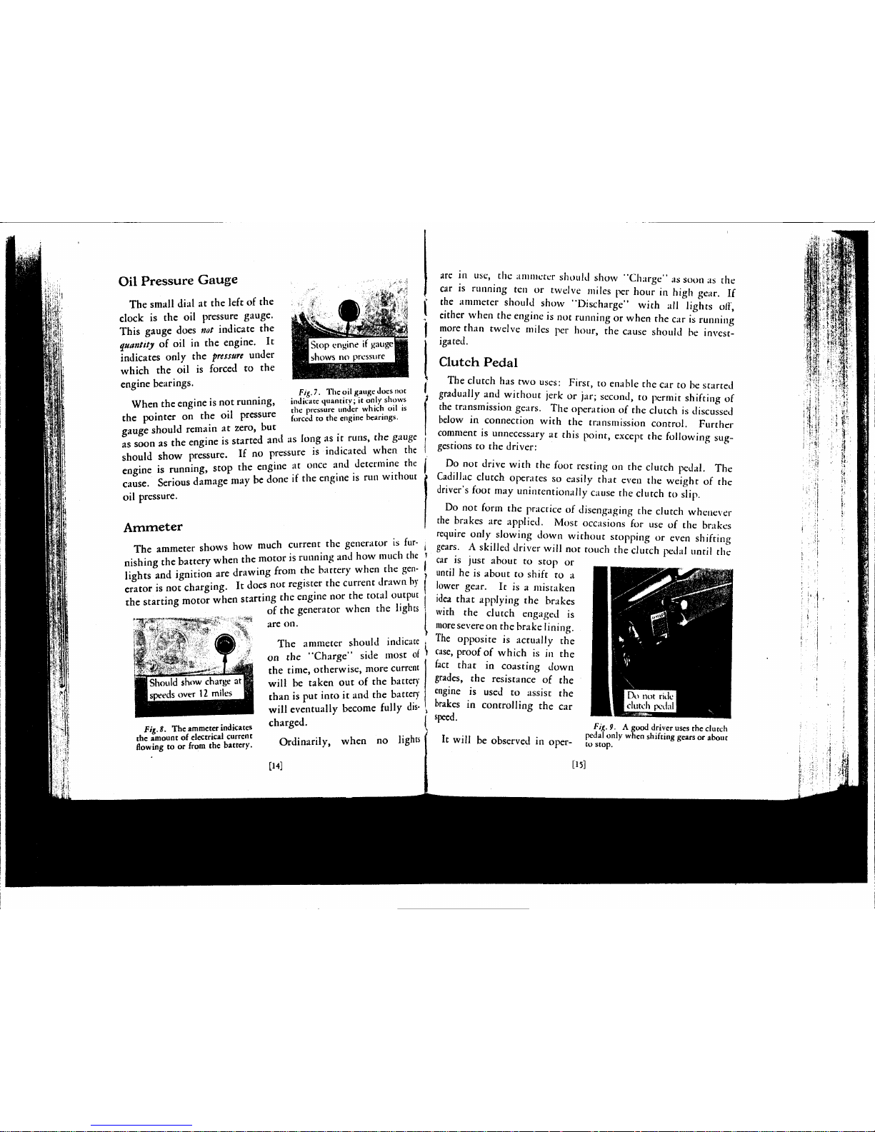
Do not drive with the foot resting on the clutch pedal. The
Cadillac clutch operates so easily that even the weight of the
driver's foot may unintentionally cause the clutch to slip.
Do not form the practice of disengaging the clutch whenever
the brakes are applied. Most occasions for use of the brakes
require only slowing down without stopping or even shifting
gears.
A skilled driver will not touch the clutch pedal until the
car is just about to stop or
until he is about to shift to a
lower gear. It is a mistaken
idea that applying the brakes
with the clutch engaged is
more
severe on the brake lining.
The opposite is actually the
case,
proof of which is in the
fact that in coasting down
grades, the resistance of the
engine is used to assist the
brakes in controlling the car
speed.
Ordinarily, when no lights
[H]
It will be observed in oper-
Fig.9. A good driver uses the clutch
pedal only when shifting gears or about
to stop.
[15]
m
' e?8
&l>i
tm
U3
.1»
• *
i +
$H*
;i
w
1..1
I
1 <t-
i a,
Page 9
ating the clutch pedal that the pedal oilers almost no resistance until it has been moved about one inch. It is at this >
point that it actually begins to disengage the clutch. It is J
important that the pedal have this "lost motion." If the full pressure of the clutch springs is felt just as soon as
the control pedal is moved, the control rod should be read-
justed. Failure to make this adjustment will result in the
clutch slipping.
Transmission Control
The operation of the Cadillac Syncro-mesh transmission is,
in general, the same as the operation of the conventional selective sliding-gear type of transmission. The positions of the i
control lever for the various speed combinations are the same t
and the directions in which the control lever is moved are the |
same. It is also necessary to disengage the clutch before moving
the control lever, the same as with the conventional transmission.
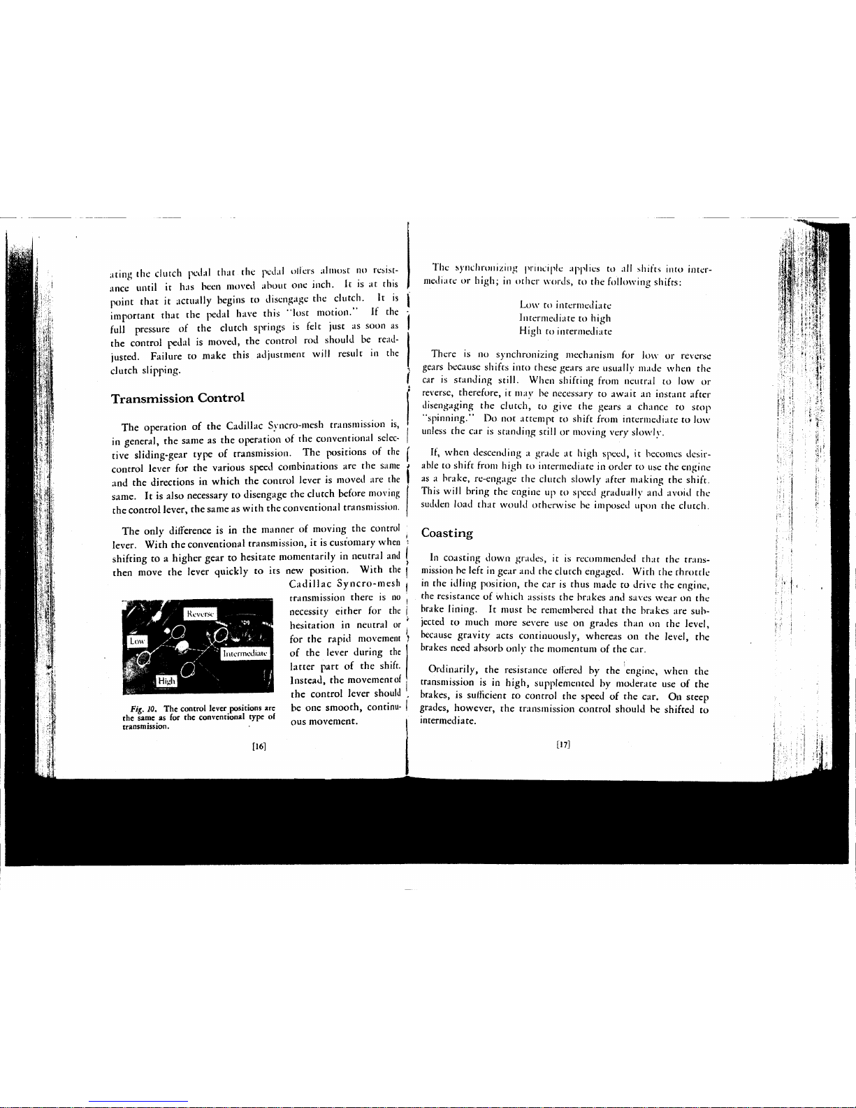
The only difference is in the manner of moving the control
lever. With the conventional transmission, it is customary when •
shifting to a higher gear to hesitate momentarily in neutral and I
then move the lever quickly to its new position. With the I
Cadillac Syncro-mesh j
transmission there is no
necessity either for the j
hesitation in neutral or
for the rapid movement ?
of the lever during the
latter part of the shift.
Instead, the movement
of
the control lever should ,
Fig.
10.
The control lever positions are be one smooth, Continu- |
the same as for the conventional type of
transmission. . ous movement. I
[161
The synchronizing principle applies to all shifts into inter-
mediate or
high;
in other words, to the following shifts:
Low to intermediate
Intermediate to high
High to intermediate
There is no synchronizing mechanism for low or reverse
gears because shifts into these gears are usually made when the
car is standing still. When shifting from neutral to low or
reverse, therefore, it may be necessary to await an instant after
disengaging the clutch, to give the gears a chance to stop
"spinning." Do not attempt to shift from intermediate to low
unless the car is standing still or moving very slowly.
If, when descending a grade at high speed, it becomes desir-
able to shift from high to intermediate in order to use the engine
as a brake, re-engage the clutch slowly after making the shift.
This will bring the engine up to speed gradually and avoid the
sudden load that would otherwise be imposed upon the clutch.
Coasting
In coasting down grades, it is recommended that the transmission be left in gear and the clutch engaged. With the throttle
in the idling position, the car is thus made to drive the engine,
the resistance of which assists the brakes and saves wear on the
brake lining. It must be remembered that the brakes are subjected to much more severe use on grades than on the level,
because gravity acts continuously, whereas on the level, the
brakes need absorb only the momentum of the car.
Ordinarily, the resistance offered by the engine, when the
transmission is in high, supplemented by moderate use of the
brakes, is sufficient to control the speed of the car. On steep
grades, however, the transmission control should be shifted to
intermediate.
[17]
Page 10
Do not turn oil the ignition when coasting with the car
driving the engine. Contrary to a common impression, this
does not appreciably increase the resistance, and is likely to
cause damage to the engine. Even with the throttle closed,
some fuel is admitted to the cylinders, and if this is not burned,
it condenses on the cylinder walls and washes away the oil
which lubricates the pistons.
Brakes
The foot brakes are internal brakes of the shoe type, applied
on all four wheels through a mechanical linkage.
When applying the brakes while driving on wet asphalt streets
or slippery roads more care should be exercised and more time
should be allowed for stopping the car than is necessary on dry
pavements. The brakes should be applied gently while the
clutch is still
engaged.
The clutch should not be released until
the car has almost stopped.
Do not attempt sudden stops. Cadillac four-wheel brakes
minimize the possibility of skidding under slippery conditions,
but their effectiveness should not induce anyone to drive less
carefully.
As the brake lining wears, the pedal must be pushed farther
down to apply the brakes. Do not wait until the pedal goes all
the way to the floor board before having the brakes readjusted.
Readjustment is recommended as soon as the pedal must be
pushed down to within one inch of the floor board. A temporary
adjustment of the brakes is explained on page 46.
For parking, the brakes are operated by the hand lever at the
right of the transmission control lever.
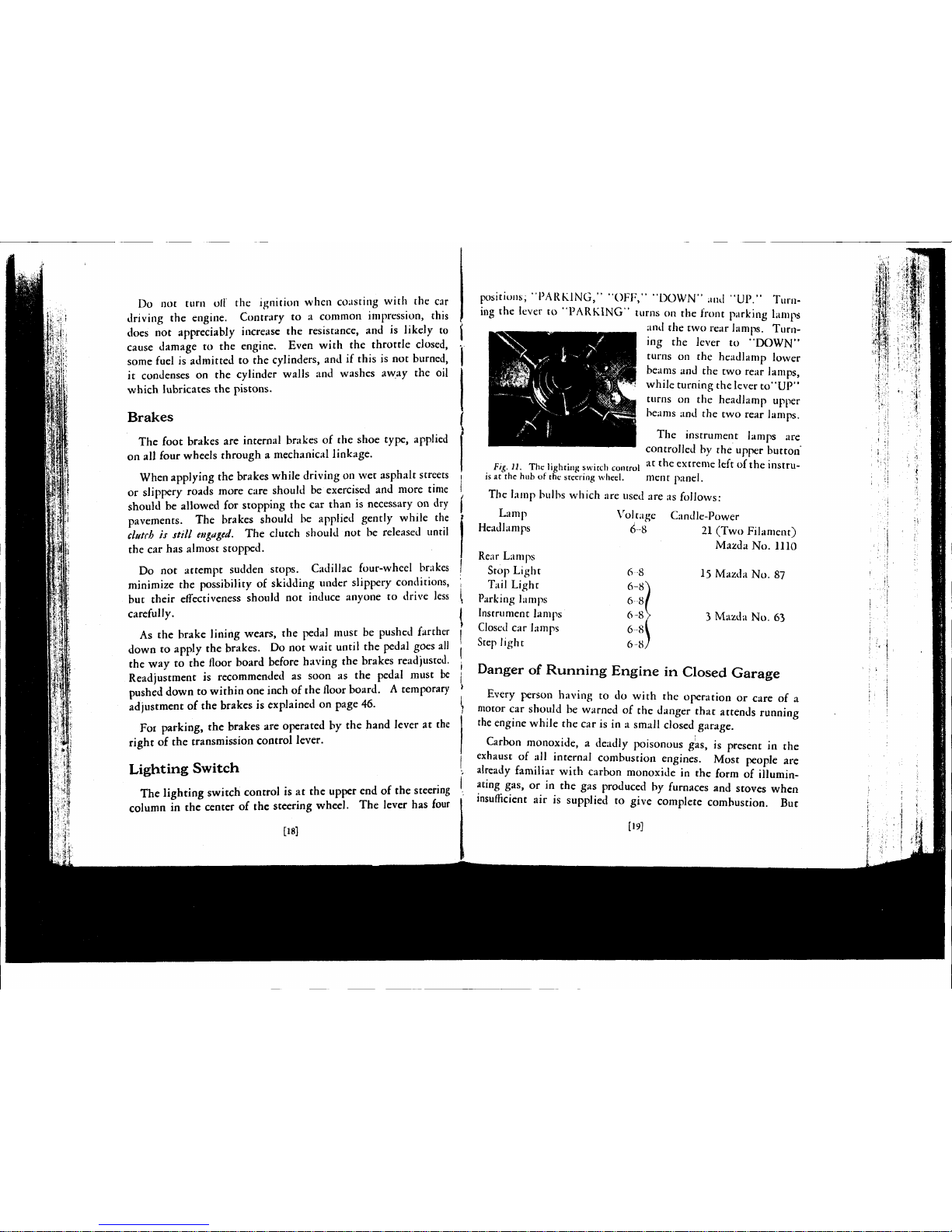
Lighting Switch
The lighting switch control is at the upper end of the steering
column in the center of the steering wheel. The lever has four
[18]
positions, -PARKING," "OFF," "DOWN" and "UP." Turn-
ing the lever to "PARKING" turns on the front parking lamps
and the two rear lamps. Turning the lever to "DOWN"
turns on the headlamp lower
beams and the two rear lamps,
while turning the lever to"UP"
turns on the headlamp upper
beams and the two rear lamps.
The instrument lamps are
controlled by the upper button
_.,,_.,... • , i at the extreme left of the instru-
Fig. )1. The lighting switch control
is at the hub of the steering wheel. ment panel.
The lamp bulbs which are used are as follows:
Lamp
Headlamps
Rear Lamps
Stop Light
Tail Light
Parking lamps
Instrument lamps
Closed car lamps
Step light
Vol tage
u
6-8
6-a\
6 8/
6-8V
6-81
6-8/
Candle-Power
21 (Two Filament)
Mazda No. 1110
15 Mazda No. 87
3 Mazda No. 63
Danger of Running Engine in Closed Garage
Every person having to do with the operation or care of a
motor car should be warned of the danger that attends running
the engine while the car is in a small closed garage.
Carbon monoxide, a deadly poisonous gas, is present in the
exhaust of all internal combustion engines. Most people are
already familiar with carbon monoxide in the form of illuminating gas, or in the gas produced by furnaces and stoves when
insufficient air is supplied to give complete combustion. But
[19]
Page 11
illuminating gas and coal gas have an unpleasant odor, which
serves as a warning, whereas carbon monoxide, as produced in
the internal combustion engine, is colorless, tasteless and almost
odorless, so that the victim may be overcome before he is aware
of the.danger. When the engine exhausts into the open air,
the carbon monoxide is so diluted that it has no effect. It is
when the engine is run for a time in a closed room that the proportion of carbon monoxide in the air may increase to the point
at which continued breathing of it would be fatal. The United
States Public Health Service advises that the average automobile
engine warming up in a single car garage will give off enough
carbon monoxide in three minutes to endanger life.
Proper precaution must be taken in cold weather when the
natural tendency is to keep the garage doors and windows
closed. The practice of letting the engine warm up in a closed
garage before opening the doors is unsafe. The risk is made
greater By the fact that the enriching of the mixture by manipulation of the carburetor choke increases the amount of carbon
monoxide formed.
[201
CHAPTER III
EQUIPMENT
I
N
addition to the controls and instruments used in driving,
the car is equipped with various devices which are for the
convenience and comfort of the occupants, and are used only as
occasion demands. It is suggested that the driver anticipate his
use of such equipment by becoming familiar at once with the
directions contained in this chapter.
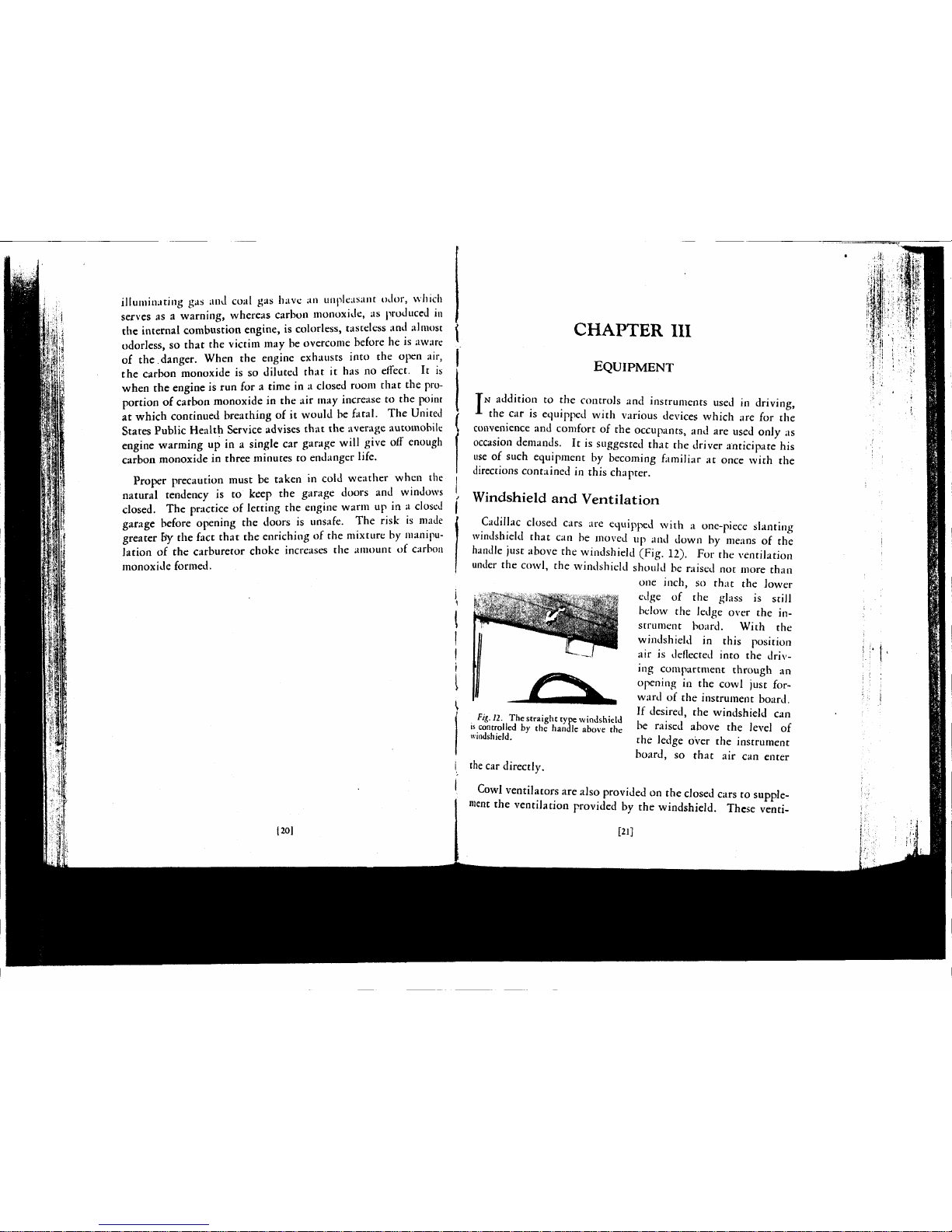
Windshield and Ventilation
Cadillac closed cars are equipped with a one-piece slanting
windshield that can be moved up and down by means of the
handle just above the windshield (Fig. 12). For the ventilation
under the cowl, the windshield should be raised not more than
one inch, so that the lower
edge of the glass is still
below the ledge over the in-
strument board. With the
windshield in this position
air is deflected into the driving compartment through an
opening in the cowl just forward of the instrument board.
If desired, the windshield can
be raised above the level of
the ledge over the instrument
board, so that air can enter
Fig.
12.
The straight type windshield
is controlled by the handle above the
windshield.
the car directly.
Cowl ventilators are also provided on the closed cars to supple-
ment the ventilation provided by the windshield. These venti-
[21]
Page 12
lators are at the sides of the cowl compartment and open toward
the rear, serving as outlets for the air entering under the windshield.
In warm weather, satisfactory ventilation in the front com-
partment cannot be expected unless the hood doors are open.
Ordinarily, these should be opened at the beginning of warm
weather and left open for the season. The temperature in the
front compartment can thereafter be controlled by the windshield
and ventilators.
Windshield Cleaner
The windshield cleaner consists of two wiper blades, operated
by the suction or vacuum in the intake manifold on the engine.
The cleaner is controlled by the lower button at the extreme lefthand end of the instrument board. This button, when pulled
all the way out, will cause one blade to work on each half of the
windshield, cleaning the entire glass. Pulling the button half
way out will cause both blades to operate on the left hand half
of the windshield, cleaning only the part in front of the driver.
To park both blades at the extreme left of the windshield when
they are not needed to clean the glass, pull the control button
half way out, wait until the left-hand blade travels over to meet
the right-hand blade and returns with it to the left-hand side;
then push the button all the way in.
Adjustable Seat
The front seat is adjustable on all Cadillac closed cars, except
those that are intended to be chauffeur-driven. Except on the
five passenger coupe, the entire front seat can be moved forward
or backward. This adjustment is controlled by a handle on the
center of the seat base, just above the floorboards. As the front
seat on the five-passenger coupe is divided, only the driver's
half of the seat is adjustable.
[22]
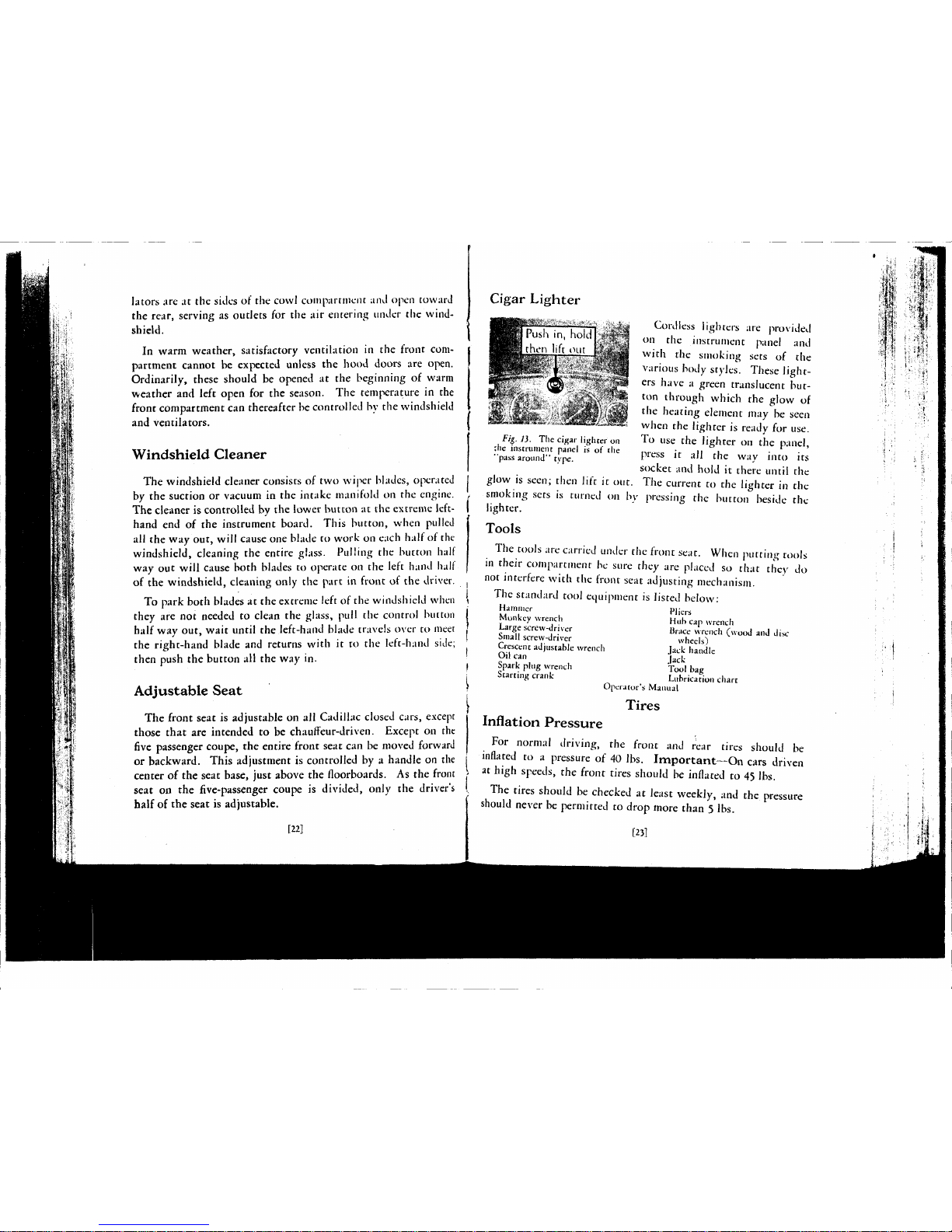
Cigar Lighter
[Push in, hold
lift out
aa^Wi"
i, - • ?,>. ':*•»
-,¾¾¾¾
}
'^- ^mw-*^
I!<KIMII;
Cordless lighters are provided
on the instrument panel and
with the smoking sets of the
various body styles. These light-
ers have a green translucent button through which the glow of
the heating element may be seen
when the lighter is ready for use.
To use the lighter on the panel,
press it all the way into its
socket and hold it there until the
The current to the lighter in the
pressing the button beside the
Fig. 1). The
cigar
lighter
on
;he
instrument
panel
is of the
"pass
around"
type.
glow is seen; then lift it out.
smoking sets is turned on b\
lighter.
Tools
The tools are carried under the front scat. When putting tools
in their compartment be sure they are placed so that they do
not interfere with the front seat adjusting mechanism.
The standard tool equipment is listed below:
Hammer
Pliers
Monkey wrench
Huh cap
wrench
Large screw-driver Brace
wrench
(wood
and
disc
Small
screw-driver wheels)
Crescent
adjustable
wrench
Jack
handle
Oil can
Jack
Spark plug
wrench
Tool
bag
Starting
crank Lubrication
chart
Operator's
Manual
Tires
Inflation Pressure
For normal driving, the front and rear tires should be
inflated to a pressure of 40 lbs. Important—On cars driven
at high speeds, the front tires should be inflated to 45 lbs.
The tires should be checked at least weekly, and the pressure
should never be permitted to drop more than 5 lbs.
,1¼
•iV
[23]
Page 13
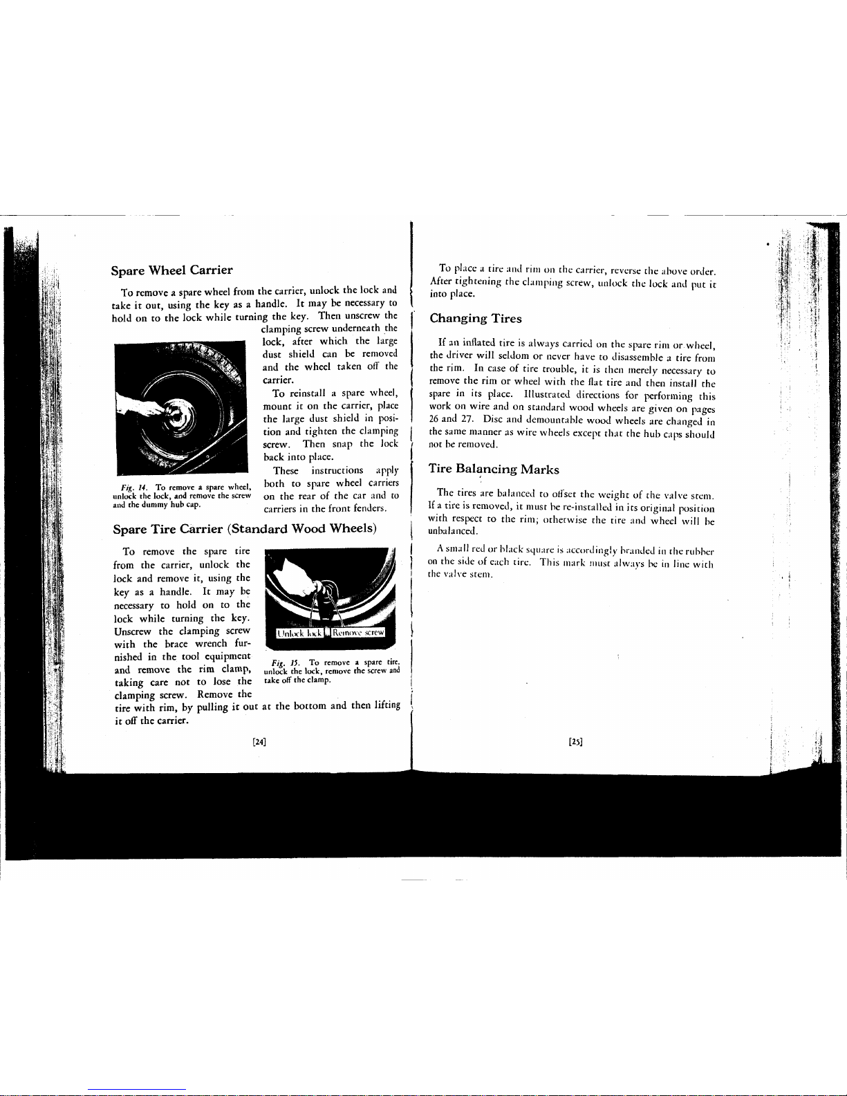
Spare Wheel Carrier
To remove a spare wheel from the carrier, unlock the lock and
take it out, using the key as a handle. It may be necessary to
hold on to the lock while turning the key. Then unscrew the
clamping screw underneath the
lock, after which the large
dust shield can be removed
and the wheel taken off the
carrier.
To reinstall a spare wheel,
mount it on the carrier, place
the large dust shield in position and tighten the clamping
screw. Then snap the lock
back into place.
These instructions apply
both to spare wheel carriers
on the rear of the car and to
carriers in the front fenders.
Fig. 14. To remove a spare wheel,
unlock the lock, and remove the screw
and the dummy hub cap.
Spare Tire Carrier (Standard Wood Wheels)
To remove the spare tire
from the carrier, unlock the
lock and remove it, using the
key as a handle. It may be
necessary to hold on to the
lock while turning the key.
Unscrew the clamping screw
with the brace wrench furnished in the tool equipment
and remove the rim clamp,
taking care not to lose the
clamping screw. Remove the
tire with rim, by pulling it out
it off the carrier.
Fig. 15. To remove a spare tire,
unlock the lock, remove the screw and
take off the clamp.
at the bottom and then lifting
[24]
To place a tire and rim on the carrier, reverse the above order.
After tightening the clamping screw, unlock the lock and put it
into place.
Changing Tires
If an inflated tire is always carried on the spare rim or wheel,
the driver will seldom or never have to disassemble a tire from
the rim. In case of tire trouble, it is then merely necessary to
remove the rim or wheel with the flat tire and then install the
spare in its place. Illustrated directions for performing this
work on wire and on standard wood wheels are given on pages
26 and 27- Disc and demountable wood wheels are changed in
the same manner as wire wheels except that the hub caps should
not be removed.
Tire Balancing Marks
The tires are balanced to offset the weight of the valve stem.
If a tire is removed, it must be re-installed in its original position
with respect to the rim; otherwise the tire and wheel will be
unbalanced.
A
small red or black square is accordingly branded in the rubber
on the side of each tire. This mark must always be in line with
the valve stem.
[25]
Page 14
,1
!
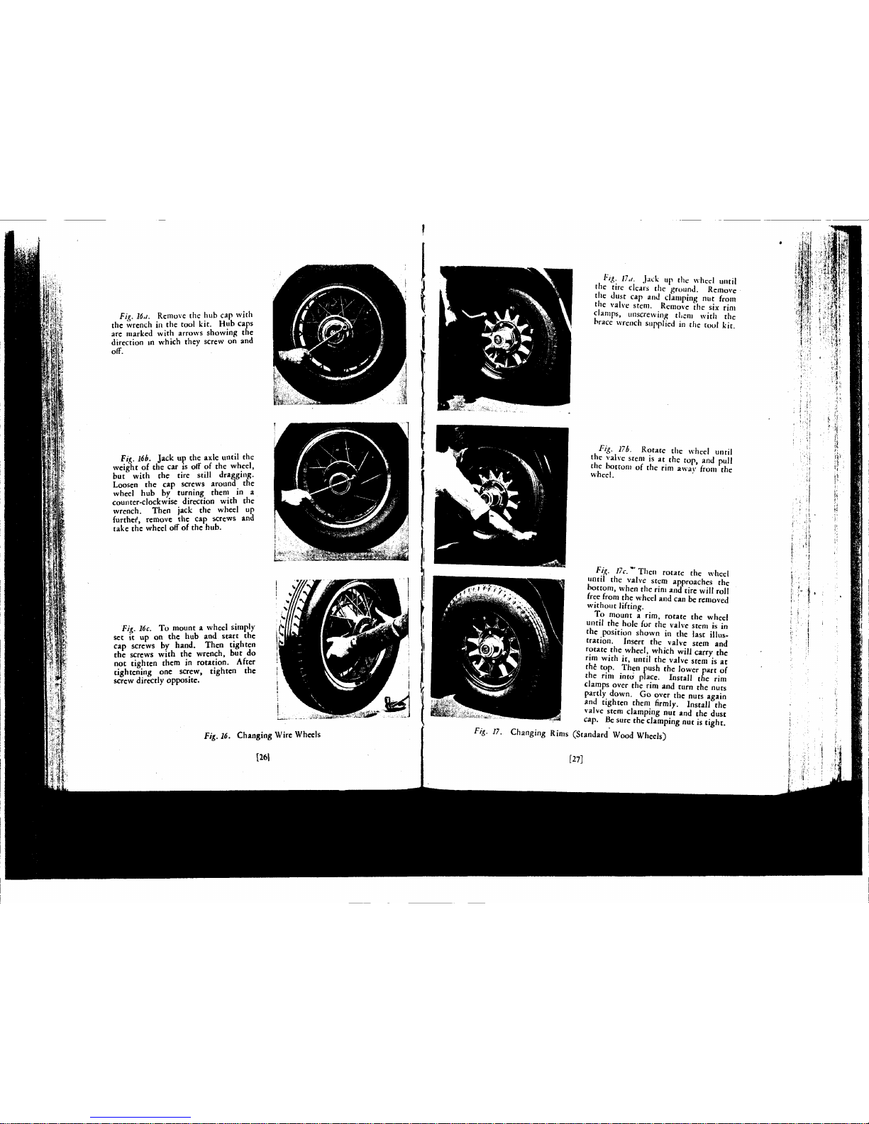
Fig. 16a. Remove the hub cap with
the wrench in the tool kit. Hub caps
are marked with arrows showing the
direction in which they screw on and
off.
Fig.
16b.
Jack up the axle until the
weight of the car is off of the wheel,
but with the tire still dragging.
Loosen the cap screws around the
wheel hub by turning them in a
counter-clockwise direction with the
wrench. Then jack the wheel up
further, remove the cap screws and
take the wheel off of the hub.
Fig.
16c.
To mount a wheel simply
sec it up on the hub and start the
cap screws by hand. Then tighten
the screws with the wrench, but do
not tighten them in rotation. After
tightening one screw, tighten the
screw directly opposite.
Fig. 16. Changing Wire Wheels
[261
tig- 17u. Jack up the wheel until
the tire clears the ground. Remove
the dust cap and clamping nut from
the valve stem. Remove the six rim
clamps, unscrewing them with the
brace wrench supplied in the tool kit.
Fig. 17b. Rotate the wheel until
the valve stem is at the top, and pull
the bottom of the rim away from the
wheel.
Fig. 17c."Then rotate the wheel
until the valve stem approaches the
bottom, when the rim and tire will roll
free from the wheel and can be removed
without lifting.
To mount a rim, rotate the wheel
until the hole for the valve stem is in
the position shown in the last illustration. Insert the valve stem and
rotate the wheel, which will carry the
rim with it, until the valve stem is at
th£ top. Then push the lower part of
the rim into place. Install the rim
clamps over the rim and turn the nuts
partly down. Go over the nuts again
and tighten them firmly. Install the
valve stem clamping nut and the dust
cap.
fie sure the clamping nut is tight.
(Standard Wood Wheels)
[27]
Page 15
LUBRICATION SCHEDULE
CADILLAC
370
ENGINE
NO.
DATE DELIVERED
OO
NOT
WAIT
POR
SCHEDULE LUBRICATIONS
BEFORE ADDING ENGINE
OIL.
THE
OIL
LEVEL
SHOULD
BE
CHECKED EVERY MO
TO IM
MILES
ANO
OIL
ADDED
IF THE
INDICATOR BALL
IS
•
CLOW ••PULL." THIS
IS
ESPECIALLY
IM-
PORTANT
ON
CARS DRIVEN
AT
MICH SPEEDS.
N
0
z
<
w
(A
0
z
z
g
<
U
£
3
01
Q
Z
<
n
tf)
0
Z
z
0
h
<
o
5
a
3
J
PR
O
0
2
<
•
t
z
z
0
<
u
E
0
3
J
0
Z
<
f-
«•>
i
z
z
0
<
u
£
c
3
J
ADD LIQUID
TO
ADD ENGINE
OIL
AS NECESSARY
STARTER. GENERATOR AND
BRAKE PINS
AND
CONNECTIONS
DOOR HARDWARE
GREASE
GUN
WATER PUMP
CLUTCH RELEASE BEARING
AND BRAKE A SSI ST ER
•ADO WATER
TO
STORAGE BATTERY
CHECK TIRE INFLATION
DRAIN
AND
REPLACE
TEST
OIL
FILTER
TRANSMISSION—ADO LUBRICANT
RE
STI
EER1NG GEAR—ADO
ONT
BRAKE TRUNNIONS
AND
SPEEDOMETER DRIVE SHAFT
FAN
••REFILL SHOCK ABSORBERS
••REPLACE
OIL
FILTER CARTRIDGE
AND CLEAN
OIL PAN
AND SCREEN
LUBRICANT
WATER
OR
ANTI-PREC2E
ENGINE
OIL
ENGINE
OIL
ENGINE
OIL
ENGINE
OIL
CHASSIS
GREASE
WATER PUMP
GREASE
WHEEL BEARING
GREASE
Dl STILLED
WATER
ENGINE
OIL
GEAR
LUBRICANT
GEAR
LUBRICANT
GEAR
LUBRICANT
LIGHT
ENGINE
OH.
CHASSIS
GREASE
WHEEL BEARING
GREASE
CHASSIS
GREASE
CHASSIS
QREASB
SPECIAL ON.
LUBRICATION
NO. AND
MILEAGE
AT
WHICH
DUE
1
I
o
o
o
o
o
o
o
o
o
o
t
i
o
o
o
o
o
o
o
o
o
o
o
1
?
o
o
o
o
o
o
o
o
o
o
o
o
o
o
I
§
o
o
o
o
o
o
o
o
o
o
o
I
1
0
o
0
o
o
o
o
o
o
o
•
1
o
o
o
o
o
o
o
o
o
o
o
o
o
o
o
o
o
o
o
o
J
I
o
o
o
o
o
o
o
o
o
o
•
I
o
o
o
o
o
o
o
o
o
o
o
•
1
o
o
o
o
o
o
o
o
o
o
o
o
o
o
10
I
o
o
o
o
u
o
o
o
o
o
o
EVERY 12.000 MILES
II
1
o
o
o
o
o
o
o
o
o
o
11
1
o
o
u
u
o
o
o
o
o
o
o
u
o
o
o
o.
o
o
o
o
o
•IN
SUMMER INSPECT BATTERY EVERY
see
MILES
OR
AT
LEAST
EVERT t WEEKS.
•*RECOfcmFNDED BUT NOT INCLUOEO IN LUBRICATIONS 0 AND 11.
THE FOLLOWING OPERATIONS CANNOT
BE
PLACED
ON A
MILEAGE BASIS
AND ARE NOT
INCLUDED
IN
THE ABOVE SCHEDULE
THIN REAR AXLE AND TRANSMISSION LUBRICANT-AS REQUfREQ
f>OR
LOW TEMPERATURES.
DRAIN
AND
REPLACE REAR AXLE
AND
TRANSMISSION LUBRICANT—AT BEGINNING
OP
MILD WEATHER
IN SPRING.
RECORD
ON
OTHER SIDE
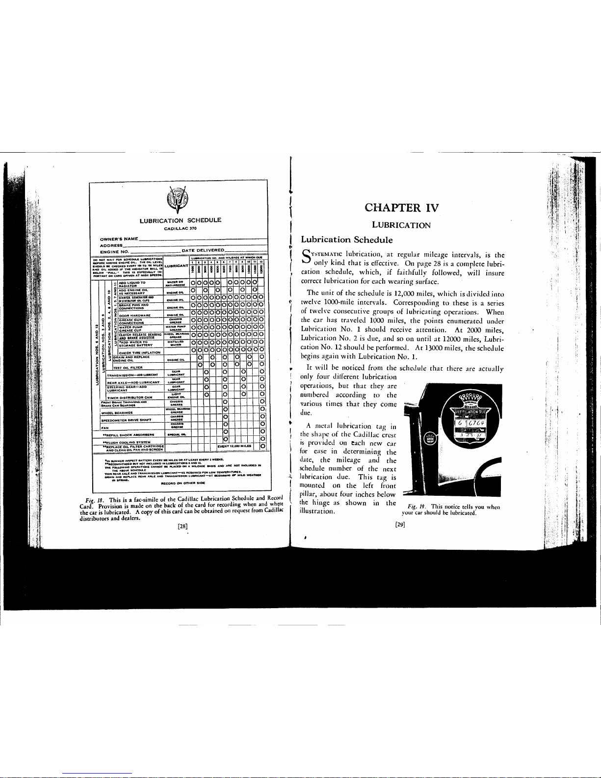
Fig.
18.
This
is a
fac-simile
of the
Cadillac Lubrication
Schedule
and
Record
Card.
Provision
is
made
on the
back
of the
card
for
recording
when
and
where
the
car
is
lubricated. A copy
of
this
card
can be
obtained
on
request
from
Cadillac
distributors
and
dealers.
[28]
CHAPTER
IV
LUBRICATION
Lubrication Schedule
S
YSTEMATIC
lubrication,
at
regular mileage intervals,
is the
only kind that
is
effective.
On
page
28 is a
complete lubri-
cation schedule, which,
if
faithfully followed, will insure
correct lubrication
for
each wearing surface.
The unit
of the
schedule
is
12,000 miles, which
is
divided into
twelve 1000-mile intervals. Corresponding
to
these
is a
series
of twelve consecutive groups
of
lubricating operations. When
the
car has
traveled
1000
miles,
the
points enumerated under
Lubrication
No. 1
should receive attention.
At
2000 miles,
Lubrication
No.
2 is
due,
and so on
until
at
12000 miles, Lubri-
cation
No. 12
should
be
performed.
At
13000 miles,
the
schedule
begins again with Lubrication
No.
1.
It will
be
noticed from
the
schedule that there
are
actually
only four different lubrication
operations,
but
that they
are
JttKKKKtBSBBtEKL
numbered according the
^^^^I^K^KUS^BH
various times that they come
J-^^^^H^H^E^^BHSI
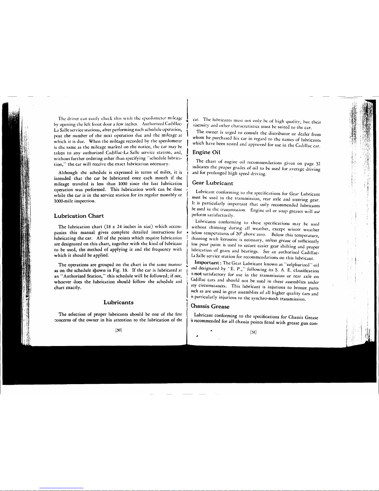
A metal lubrication
tag in
HHH ^•liUailiO^Br
the shape
of the
Cadillac crest Hui^M
^¾
«>iIIIMR
mmW
is provided
on
each
new car
^MS_§Sj ^^gjgppV^
for ease
in
determining
the
fll^^l
date,
the mileage and the
^BBBI
^^
schedule number
of the
next
HBRH
j^'
lubrication
due.
This
tag is
wK^m^JM»'s-t^^^^mmm1mWM
mounted
on the
left JpH^Hsfl^BBR^HsBR^Lfl
pillar, about four inches below
:^"»MBB^B^^E^B^BB»T4^^B«
the hinge
as
shown
in the
Fig M_ This noticc
Kl|s you
when
illustration.
your
car
should
be
lubricated.
[29]
I
Page 16
The driver can easily check this with the speedometer mileage
by opening the left front door a few inches. Authorized CadillacLa Salle service stations, after performing each schedule operation,
post the number of the next operation due and the mileage at
which it is due. When the mileage recorded by the speedometer
is the same as the mileage marked on the notice, the car may be
taken to any authorized Cadillac-La Salle service station, and,
without further ordering other than specifying "schedule lubrication," the car will receive the exact lubrication necessary.
Although the schedule is expressed in terms of miles, it is
intended that the car be lubricated once each month if the
mileage traveled is less than 1000 since the last lubrication
operation was performed. This lubrication work can be done
while the car is in the service station for its regular monthly or
1000-mile inspection.
Lubrication Chart
The lubrication chart (18 x 24 inches in size) which accompanies this manual gives complete detailed instructions for
lubricating the car. All of the points which require lubrication
are designated on this chart, together with the kind of lubricant
to be used, the method of applying it and the frequency with
which it should be applied.
The operations are grouped on the chart in the same manner
as on the schedule sfrown in Fig. 18. If the car is lubricated at
an "Authorized Station," this schedule will be followed; if not,
whoever does the lubrication should follow the schedule and
chart exactly.
Lubricants
The selection of proper lubricants should be one of the first
concerns of the owner in his attention to the lubrication of the
[301
car. The lubricants must not only be of high quality, but their
i viscosity and other characteristics must be suited to the car.
t The owner is urged to consult the distributor or dealer from
whom he purchased his car in regard to the names of lubricants
J which have been tested and approved for use in the Cadillac car.
I Engine Oil
f
I The chart of engine oil recommendations given on page 32
I indicates the proper grades of oil to be used for average driving
) and for prolonged high speed driving.
Gear Lubricant
Lubricant conforming to the specifications for Gear Lubricant
must be used in the transmission, rear axle and steering gear.
It is particularly important that only recommended lubricants
be used in the transmission. Engine oil or soap greases will not
perform satisfactorily.
Lubricants conforming to these specifications may be used
without thinning during all weather, except winter weather
below temperatures of 20° above zero. Below this temperature,
thinning with kerosene is necessary, unless grease of sufficiently
low pour point is used to secure easier gear shifting and proper
lubrication of gears and bearings. See an authorized CadillacLa Salle service station for recommendations on this lubricant.
Important: The Gear Lubricant known as "sulphurized" oil
and designated by "E. P.," following its S. A. E. classification
is not satisfactory for use in the transmission or rear axle on
Cadillac cars and should not be used in these assemblies under
any circumstances. This lubricant is injurious to bronze parts
such as are used in gear assemblies of all higher quality cars and
is particularly injurious to the synchro-mesh transmission.
Chassis Grease
Lubricant conforming to the specifications for Chassis Grease
is recommended for all chassis points fitted with grease gun con-
[31]
' '"I
IAI?^
Page 17
nections. Do not use ordinary cup grease, as such greases are
not effective enough to lubricate satisfactorily over the 1000mile interval.
Wheel Bearing Grease
Greases approved under the specifications for Wheel Bearing
Grease are suitable for lubricating the wheel bearings and the
clutch release bearing.
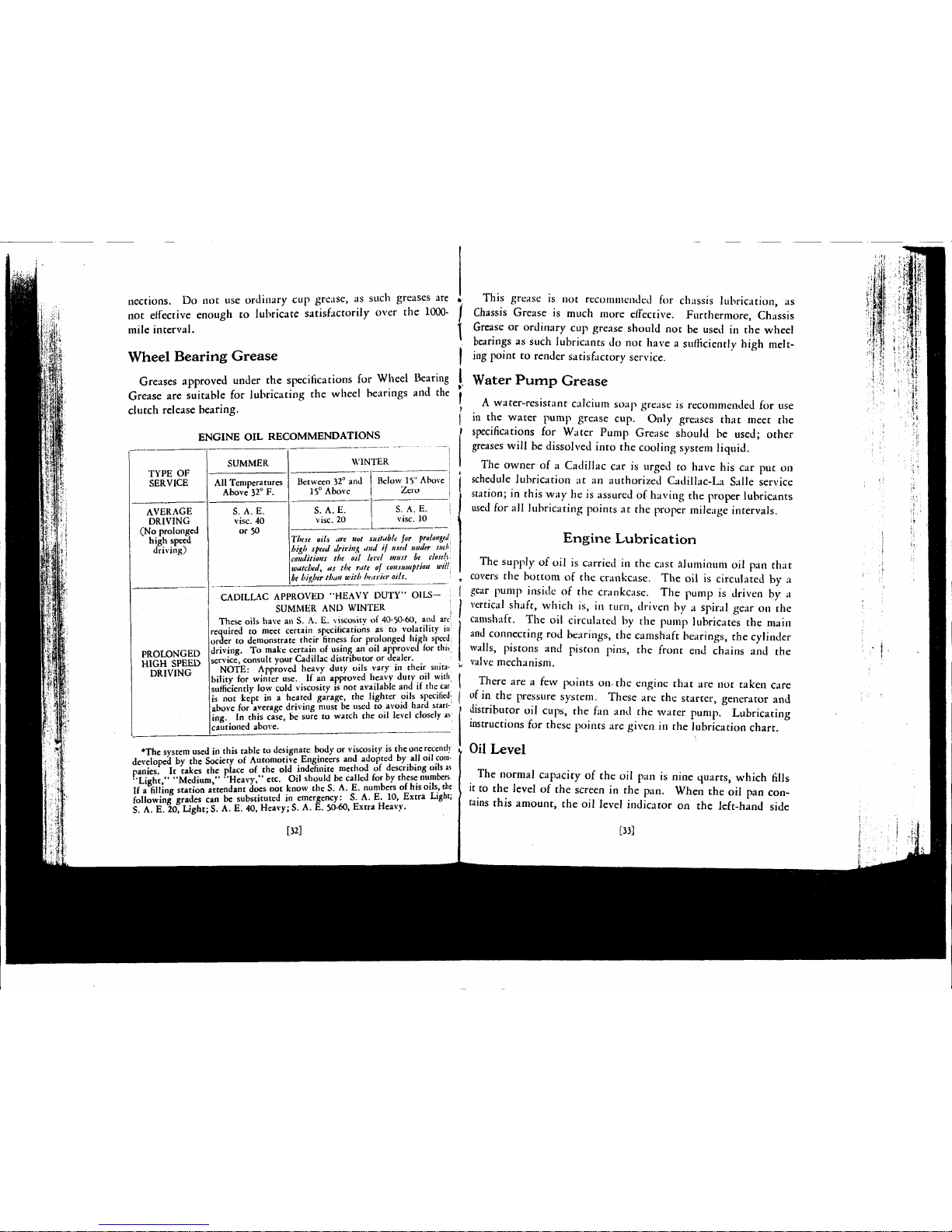
ENGINE OIL RECOMMENDATIONS
TYPE OF
SERVICE
AVERAGE
DRIVING
(No prolonged
high speed
driving)
PROLONGED
HIGH SPEED
DRIVING
SUMMER
All Temperatures
Above 32° F.
S. A. E.
vise.
40
or 50
WINTER
Between 32° and
15° Above
S. A. E.
vise.
20
Below 15° Above
Zero
S. A. E.
vise.
10
Ttiese oils are Hot suitable for
prolonged
high
speed
driving and if used
under such
conditions the oil level must be closely
watched^
as the rate of
consumption
will
be higher
than with
heavier
oils.
CADILLAC APPROVED 'HEAVY DUTY" OILS- j
SUMMER AND WINTER ;
These oils have an S. A. E. viscosity of 40-50-60, and arc'
required to meet certain specifications as to volatility in
order to demonstrate their fitness for prolonged high speed
driving. To make certain of using an oil approved for this;
service, consult your Cadillac distributor or dealer.
NOTE: Approved heavy duty oils vary in their suita-
bility for winter use. If an approved heavy duty oil with
|
sufficiently low cold viscosity is not available and if the car
is not kept in a heated garage, the lighter oils specified:
above for average driving must be used to avoid hard start-!
ing. In this case, be sure to watch the oil level closely as
cautioned above.
•The system used in this table to designate body or viscosity is the one recently
developed by the Society of Automotive Engineers and adopted by all oil companies. It takes the place of the old indefinite method of describing oils as
"Light," "Medium," "Heavy," etc. Oil should be called for by these numbers.
If a filling station attendant does not know the S. A. E. numbers of his oils, the
following grades can be substituted in emergency: S. A. E. 10, Extra Light;
S. A. E. 20, Light; S. A. E. 40, Heavy; S. A. E. 50-60, Extra Heavy.
[32]
This grease is not recommended for chassis lubrication, as
Chassis Grease is much more effective. Furthermore, Chassis
Grease or ordinary cup grease should not be used in the wheel
bearings as such lubricants do not have a sufficiently high melting point to render satisfactory service.
Water Pump Grease
A water-resistant calcium soap grease is recommended for use
in the water pump grease cup. Only greases that meet the
specifications for Water Pump Grease should be used; other
greases will be dissolved into the cooling system liquid.
The owner of a Cadillac car is urged to have his car put on
schedule lubrication at an authorized Cadillac-La Salle service
station; in this way he is assured of having the proper lubricants
used for all lubricating points at the proper mileage intervals.
Engine Lubrication
The supply of oil is carried in the cast aluminum oil pan that
covers the bottom of the crankcase. The oil is circulated by a
gear pump inside of the crankcase. The pump is driven by a
vertical shaft, which is, in turn, driven by a spiral gear on the
camshaft. The oil circulated by the pump lubricates the main
and connecting rod bearings, the camshaft bearings, the cylinder
walls,
pistons and piston pins, the front end chains and the
valve mechanism.
There are a few points on-the engine that are not taken care
of in the pressure system. These are the starter, generator and
distributor oil cups, the fan and the water pump. Lubricating
instructions for these points are given in the lubrication chart.
Oil Level
The normal capacity of the oil pan is nine quarts, which fills
it to the level of the screen in the pan. When the oil pan contains this amount, the oil level indicator on the left-hand side
[33]
Page 18
I'l^'r
a. T
ff
(I
IP'
|V J'
ih
n
4
P
r 1
h
M
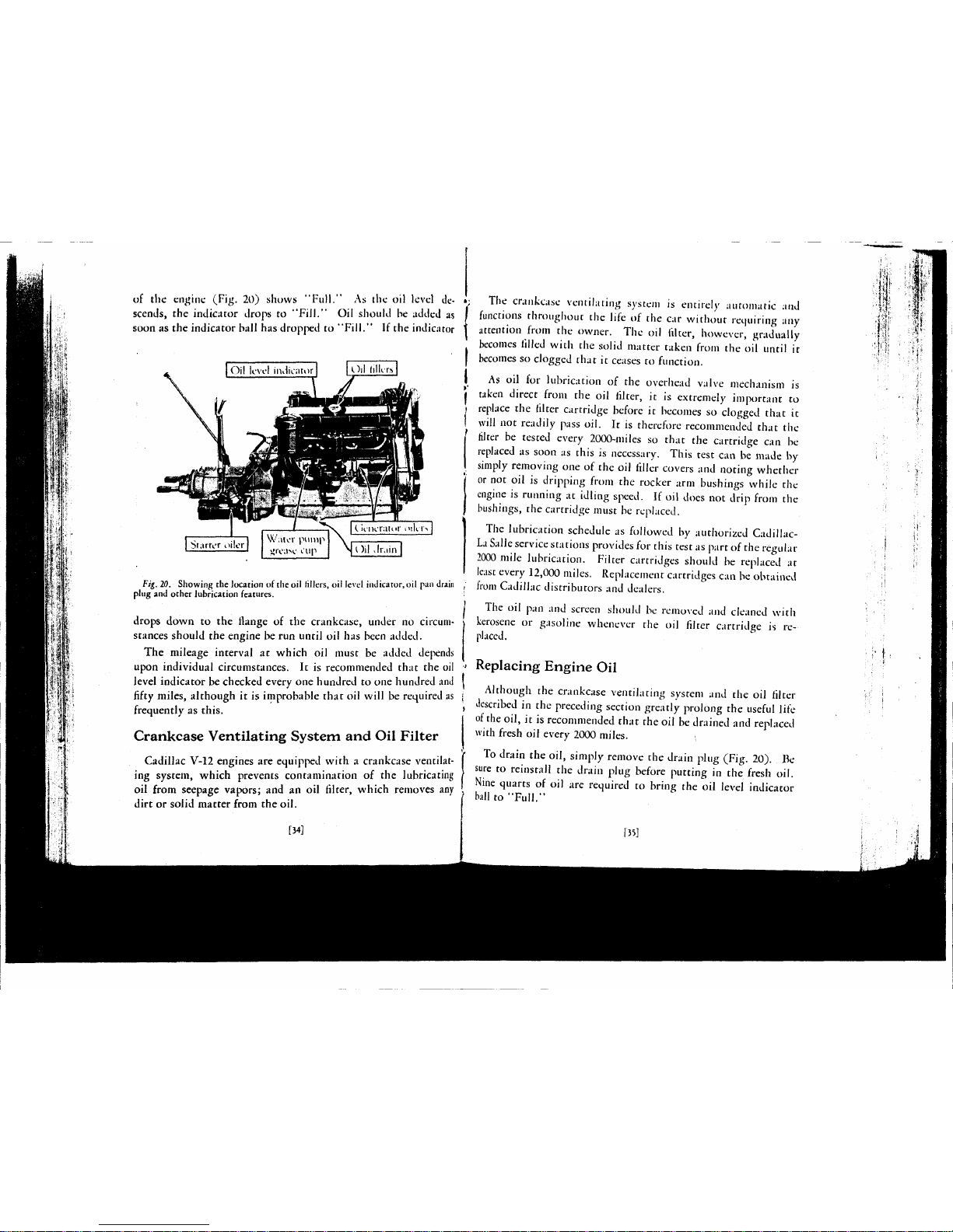
of the engine (Fig. 20) shows "Full." As the oil level descends, the indicator drops to "Fill." Oil should be added as
soon as the indicator ball has dropped to "Fill." If the indicator
Oil tillers
Starrer oiler
Wntvr ptunp
«re;iM' I'up
Oil Jr.iin
Fig. 20. Showing the location of the oil fillers, oil level indicator, oil pan drain
plug and other lubrication features.
drops down to the flange of the crankcase, under no circumstances should the engine be run until oil has been added.
The mileage interval at which oil must be added depends
upon individual circumstances. It is recommended that the oil
level indicator be checked every one hundred to one hundred and
fifty miles, although it is improbable that oil will be required as
frequently as this.
Crankcase Ventilating System and Oil Filter
Cadillac V-12 engines are equipped with a crankcase ventilating system, which prevents contamination of the lubricating
oil from seepage vapors; and an oil filter, which removes any
dirt or solid matter from the oil.
[34]
The crankcase ventilating system is entirely automatic and
functions throughout the life of the car without requiring any
attention from the owner. The oil filter, however, gradually
becomes filled with the solid matter taken from the oil until it
becomes so clogged that it ceases to function.
As oil for lubrication of the overhead valve mechanism is
taken direct from the oil filter, it is extremely important to
replace the filter cartridge before it becomes so clogged that it
will not readily pass oil. It is therefore recommended that the
filter be tested every 2000-miles so that the cartridge can be
replaced as soon as this is necessary. This test can be made by
simply removing one of the oil filler covers and noting whether
or not oil is dripping from the rocker arm bushings while the
engine is running at idling speed. If oil does not drip from the
bushings, the cartridge must be replaced.
The lubrication schedule as followed by authorized CadillacLa Salle service stations provides for this test as part of the regular
2000 mile lubrication. Filter cartridges should be replaced at
least every 12,000 miles. Replacement cartridges can be obtained
from Cadillac distributors and dealers.
The oil pan and screen should be removed and cleaned with
kerosene or gasoline whenever the oil filter cartridge is replaced.
Replacing Engine Oil
Although the crankcase ventilating system and the oil filter
described in the preceding section greatly prolong the useful life
of the oil, it is recommended that the oil be drained and replaced
with fresh oil every 2000 miles.
To drain the oil, simply remove the drain plug (Fig. 20). Be
sure to reinstall the drain plug before putting in the fresh oil.
Nine quarts of oil are required to bring the oil level indicator
ball to "Full."
135]
H
Page 19

CHAPTER V
COLD
WEATHER
OPERATION
OATISFACTORY
operation of the car in freezing weather depends
^-^ upon having the car prepared for cold weather and in giving
it the special attention which is required at that time. In this
chapter has been grouped all the information relating to care
and operation of the car during cold weather. It should be
reviewed just prior to the beginning of the winter season.
Preparing
for
Cold
Weather
Anti-Freezing
Solutions
The available commercial materials for preparing anti-freezing
solutions for automobile radiators are denatured alcohol, methanol (synthetic wood alcohol), distilled glycerine, and ethylene
glycol.
Denatured alcohol and methanol solutions are, at present, the
most generally used anti-freezing solutions. These preparations
are widely distributed, afford protection against freezing, and are
not injurious to the cooling system.
There are two principal objections to denatured alcohol and
methanol—they are lost by evaporation, and are harmful to the
car finish. Any material accidentally spilled on the finish should
be flushed off immediately with a large quantity of water.
Solutions of these materials in the radiator must be tested
periodically and sufficient methanol or alcohol should be added to
replace the loss by evaporation. Otherwise, the engine or radiator, or both, are likely to be damaged by freezing. Evaporation
is much more rapid on heavy runs, and the solution should be
tested more often under such circumstances.
Methanol, for aiiti-Jrceze purposes, is sold in the United States
in the correct concentration to give the same protection against
freezing as denatured alcohol. The table below may be used for
both denatured alcohol and methanol.
Lowest
Temperature
Ex-pec tcJ
10 F.
0 F.
-10 F.
—20 F.
-30 F.
Per cent
In
Volume
30
38
45
51
57
Specific <-i
1,at 60"
Ocuamrct AKi>lml
.9668
.9567
.9475
.9350
.9260
ravitv
IV) •
MdllJH,"
.972
.964
.957
.950
.944
Qts.
Alcohol
required to make
6 pals, solution
Vx
9)
A
10?
4
12
13*.,
I
Distilled glycerine and ethylene glycol solutions are, in first
cost, more expensive than alcohol, but as they are not lost by
evaporation, only water need be added to replace evaporation
' losses, except that any solution lose mechanically, by leakage,
foaming,
etc.,
must be replaced by additional new anti-freezing
solution. These solutions under ordinary conditions are not
injurious to the car finish.
! The principal objections to glycerine and ethylene glycol arc
I the tendency of these solutions to loosen the scale and iron rust
| which forms in the water passages of the cylinder block and head,
and the difficulty of securing and maintaining tight, leak proof
connections. It is absolutely necessary to thoroughly clean and
, Hush the entire cooling system before glycerine or ethylene
glycol is used.
I It is also necessary to tighten or replace the cylinder head
I
gaskets and pump packing. The cylinder head gaskets must be
kept tight to prevent the solution from leaking into the crank-
case where it might cause gumming and sticking of the moving
( parts. The pump packing must be kept tight to prevent air
\ from being drawn into the cooling system in order to avoid
I foaming and other difficulties which may result when air is
j present.
[361
!37l
Page 20

Ethylene glycol, sold in the U. S. for anti-freezing purposes, is
chemically treated to overcome the principal difficulties men-
tioned in the above paragraph, and under normal operating conditions with tight hose connections and cylinder head gaskets
should be satisfactory for use in the cooling systems.
Glycerine or ethylene glycol should be used in accordance
with the instructions and in the proportions recommended by
the anti-freeze manufacturer.
In using a hydrometer to determine the temperature at which
a solution will freeze, the test must be made at the temperature
at which the hydrometer is calibrated. If the solution is warmer
or colder, it must be brought to this temperature or correction
must be made for the difference in temperature, otherwise large
errors may result. Freezing point hydrometers can not be used
interchangeably, a different float being required for denatured
alcohol, methanol, glycerine and ethylene glycol. In some cases
these errors may be as large as 30 degrees Fahrenheit.
Salt solutions, such as calcium or magnesium chloride, sodium
silicate, etc., honey, glucose and sugar solutions and oils are not
satisfactory for use in automobile radiators.
Capacity of Cooling System
The capacity of the cooling system is 6½ gallons when filled
to the level of the overflow pipe. The cooling system may be
filled to this level since the overflow pipe is connected to a condenser tank which operates automatically to prevent excessive
loss of the cooling liquid.
It is important that there are no leaks in the cooling system
and that the radiator cap is turned down so that it is air tight,
to insure proper operation of the condenser.
Winter Lubrication
Lubrication of the car requires special attention in winter, not
only to insure proper lubrication of the moving parts, but to
[38]
secure the same ease of operation in starting, steering and shifting
gears as during warm weather.
The chart of engine oil recommendations on page 32 gives the
proper grade of oil to be used for cold weather driving. It will
be noted that lighter oils can be used for cold weather providing
no prolonged high speed driving is done. For prolonged high
speed driving, "Heavy duty" oils must be used. Authorized
Cadillac-La Salle Service Stations are prepared with full information on winter lubrication.
The lubricant in the transmission and rear axle should be
thinned with kerosene as soon as the weather is so cold that the
transmission gears are hard to shift. If a sufficient amount of
kerosene is added to provide for the lowest winter temperature
expected, it will not be necessary to add kerosene again there-
after during the winter. Ten per cent (a little over half a pint)
of kerosene, if added, will take care of temperatures down to ten
below zero.
There are several lubricants on the market which have a low
enough pour point so that they will not require thinning. See an
authorized Cadillac-La Salle Service Station for information on
these lubricants. If one has been regularly used, no kerosene
should be added. Thinning of such a lubricant is not only unnecessary, but defeats the purpose of using it because it would
have to be drained and replaced on return of warm weather.
Steering gear lubricant, in any case, should not be thinned as
the pressure between the worm and sector will force out the
thinned lubricant, resulting in excessive wear. A lubricant of
low enough cold test so as not to require thinning should be used.
Storage Battery
The electrical system of an automobile has much more to do
in winter than in summer. The engine is harder to crank and
must usually be cranked longer before it starts. The lights are
also used to much greater extent than during the long days of
[39]
Page 21

summer. All this means that the battery must be ready for
increased demands.
It is therefore a good plan in preparing for the winter season
to see that the battery is fully charged, that the battery connections are clean and tight, and that the charging rate is sufficient
to take care of the requirements of the system.
Gasoline System
The carburetors on the Cadillac engine have automatic com- •
pensation for temperature. Nevertheless it is a good plan to
have the carburetor adjustment checked when cold weather
arrives. This inspection should give special attention to the
carburetor choke control to make sure that the enriching device
is fully effective at each carburetor when the choke button is
operated.
In warm weather, a small amount of water in the gasoline has
little or no effect on the running of the engine. In freezing
weather, however, even a small amount of water may freeze
and stop the entire flow of fuel to the carburetors. One of the
things to be done in preparing for winter weather, therefore, is
to clean the gasoline filter and the sediment chambers in the
gasoline system.
Starting the Engine
Choke Button
The first difference between starting the engine in cold weather
and starting the engine in warm weather is in the greater use ot
the choke necessary in cold weather. Gasoline does not vaporize
as readily at low temperatures, and in order to supply the cylinders with a gaseous mixture rich enough to be ignited, the
proportion of liquid gasoline to air must be increased.
At the same time, it is important not to apply the choke more
than is necessary. The unvaporized gasoline collects on the
[40]
cylinder walls and works down past the pistons, washing off
the lubricant as it goes. Although dilution of the oil supply
with this unburned gasoline is minimized by the crankcase
ventilating system, it is best to avoid an excess of liquid gasoline
in the combustion chambers by careful and judicious use of the
choke.
The following rule should govern the use of the choke in
winter weather: Pull the choke back just as far as it is necessary
to start the engine, but as soon as the engine starts, return the
button as far as possible without causing the engine to stop or
slow down. Then push the button all the way in as soon as the
engine is warm enough to permit doing so.
Priming the Carburetors
In extremely cold weather, if the engine does not start after
cranking for a few seconds with the choke button fully applied,
release the starter pedal. Then prime the carburetors by opening
and closing the throttle once or twice rather rapidly with the
accelerator. Opening and closing the throttle operates a throttle
pump on each carburetor and raises the level of the gasoline in
the carburetors. The carburetors should never be primed in
warm weather and should not be primed unnecessarily in cold
weather. Excessive priming is likely to make starting difficult
rather than easy.
Position of Throttle Hand Lever
The correct position of the throttle hand lever for starting in
cold weather is the same as for starting under other conditions,
that is, about one-fourth the way down from the idling position.
In warm weather, however, the lever may be returned to the
idling position almost as soon as the engine is started. In cold
weather the throttle must be left slightly open until the engine
becomes warm.
[41]
Page 22

Position of Spark Control
It is the practice of some drivers to retard the spark all the way
whenever starting the engine. This is the correct position if the
engine is to be cranked by hand, but if the engine is to be cranked
with the starter, the spark button should be left all the way in or
in the fully advanced position.
Use of Starter
In extremely cold weather, when the car has been standing
long enough to become thoroughly chilled, it is a good plan to
disengage the clutch during the cranking operation. If this is
not done, the starter is called upon to turn the jackshaft gears
in the transmission in addition to cranking the engine. At
ordinary temperatures, the additional energy required is negligible, but in extremely cold weather, the lubricant in the
transmission offers sufficient resistance to rotation of the transmission gears to increase considerably the demand upon the
battery and to retard the cranking speed.
Use of Accelerator before Engine is Warm
In cold weather, after the engine has been started and before
it has run long enough to become warm, the engine cannot
deliver its normal power, and it should not be called upon to do
so.
In accelerating the engine to start the car and in accelerating
the car after the transmission is in gear, do not open the throttle
suddenly or too far. To do so is not only to invite "popping
back" in the carburetors, but to increase the amount of excess
unvaporized gasoline in the combustion chambers, both of
which results are undesirable.
1 CHAPTER VI
GENERAL
CARE
TVT° attempt has been made to include in this manual direc-
•L^
tions for making adjustments or repairs to the car. Most
Cadillac owners prefer to depend for such work on authorized
Cadillac-La Salle service stations, as these stations can invariably perform the work more conveniently and economically.
Every owner should, however, know how to perform the few
simple operations of general care described in this chapter.
These operations are not difficult enough to necessitate a visit
to the service station, although this work can also be done in
the service station, if desired.
I Storage Battery
The storage battery is carried in a compartment in the righthand front fender. This compartment is enclosed by a metal
cover held down by four screws.
| The battery is filled with an acid solution from which the
water slowly evaporates, and fresh distilled water must be added
! to each of the three cells at regular intervals to bring the level
up to the bottom of the filling tubes. Distilled water should
be added at least every 1000 miles, and in warm weather, every
500 miles, or at least every two weeks. If distilled water is not
available, melted artificial ice or rain water caught in an earthenware receptacle may be used. Hydrant water or water that
has been in contact with metallic surfaces will cause trouble if
used. Acid must never be added to the battery.
[42]
[43]
Page 23

After adding water to the storage battery in freezing weather,
the car should immediately be run far enough to mix the water
and acid solution thoroughly. If the car is parked immediately '
after adding water, the water is likely to stay on top of the acid
solution and may freeze, causing extensive damage.
As the storage battery is charged and discharged, the solution
reacts chemically with the plates of the battery, the specific
gravity of the solution changing as the reaction proceeds. The
state of charge of the battery is thus indicated by the specific
gravity of the solution. As the battery is charged, the specific
gravity of the solution increases, reaching 1.270 to 1.285 when
the battery is fully charged. The specific gravity of the solution decreases as the battery is discharged. A fully discharged
battery has a specific gravity of 1.150 to
1.165.
A hydrometer is the instrument used to measure the specific
gravity of a solution. A hydrometer syringe is a hydrometer
especially designed for convenience in testing the specific gravity
of the acid solution in the storage battery. A hydrometer
syringe can be obtained at any battery service station. Be sure
and get a reliable instrument, for cheap ones may be in error as
much as 25 or 30 points.
The specific gravity of the acid solution should never be
tested immediately after adding distilled water. If the solution
is below the plates, so that it cannot be reached with the syringe,
add the necessary amount of water, then drive the car for a few
hours before taking the hydrometer reading.
Cooling System
The cooling system should be kept rilled with 6½ gallons
of
water, except in freezing weather, when a suitable anti-freezing
solution, such as those described on page 36, must be used.
[44]
The drain valve lor the cooling system is in.the water inlet
elbow at the bottom of the water pump on the right side of the
crankcase.
The cooling system should be
drained and flushed every 6000
miles.
If possible, this should
be done at a Cadillac service
station, or where there are facilities for reversing the How of
water through the radiator. If
this is not possible, use the following method:
F/g. 21. The entire cooling
system can be drained by opening this one valve.
Run the engine until the open-
ing of the radiator shutters indi-
cates that the engine is warm.
Stop the engine and immediately open the drain valve.
After the liquid has drained off, refill the cooling system with
hot water and repeat the operation described above. If, in
draining the second time, the water is very dirty, it may be
advisable to repeat the flushing operation a third time, placing
one or two handfuls of sal-soda in through the radiator filler.
The sal-soda must not be permitted to get on the finish of the
hood or radiator. If sal-soda is used, the cooling system must
be drained and flushed again before refilling for use.
Gasoline Filter
A gasoline filter (Fig. 22) is provided at the bottom of the
vacuum tank. The filter has a glass bowl through which the
accumulation of water and sediment can be easily seen. The bowl
should be removed and the gauze screen should be cleaned as soon
[45]
Page 24

as any accumulation appears in the bowl. This can be done as
follows:
First shut off the gasoline by turning clockwise the small
T-handle valves at each side of the filter. Then unscrew the
thumb nut under the bowl, after which the yoke supporting the
bowl can be swung to one side and the bowl can be removed. If
the screen does not come off with the bowl, it can be removed
by pulling it straight down.
In putting back the bowl,
make sure that it seats properly against the cork gasket in
the top of the filter before
tightening the thumb screw.
Do not forget to turn the
gasoline on by opening both
valves.
be removed and cleansed regularly.
There is also a strainer in
the vacuum tank at the point
where the gasoline enters the
inner chamber. This strainer should be removed and cleaned
occasionally. It is accessible after disconnecting the feed pipe
and unscrewing the inlet elbow.
Temporary Brake Adjustment
It is recommended that all adjustments of the brakes be done
at an authorized Cadillac-La Salle service station. In an emergency, however, the following temporary adjustment can be
made by the driver.
Each brake is fitted with an adjusting nut on the cam lever,
as shown in Fig. 23. To tighten the brake adjustment turn all
[46]
• four adjusting nuts half a turn clockwise. These adjusting nuts
lock each sixth of a turn.
fig. 22. The gasoline filter should
F/j.
23. A temporary brake adjustment can be secured by turning the adjusting
j nut on each brake clockwise one-halt turn. The front brake is shown above at
the left, the rear brake at the right.
Body
Care of Finish
The lacquer finish of Cadillac bodies can be kept new and
lustrous with the simplest care. The car should merely be
wiped off every few days with a soft dry cloth. An occasional
polishing with some recognized lacquer polish (for sale by all
Cadillac distributors and dealers) will prove beneficial.
If the finish receives this attention at regular intervals, it
will not need to be washed, except when it. has accumulated
a considerable amount of mud or dust. When washing the car,
use
plenty of clean cold water. Do not use hot water, and do not
wash the hood while it is hot, as this will in time destroy the
luster. Do not use soap.
If a hose is used in washing, do not use a nozzle, but let the
water flow gently from the hose and flush off the dirt gradually.
A
soft wool sponge can be used to advantage in removing dirt.
After the washing is completed, squeeze the sponge as dry as
possible and pick up all water from crevices. Then thoroughly
[47]
Page 25

wet a clean soft chamois, wring it as dry as possible and dry the
finish. The finish can then be rubbed with a clean soft cloth to
bring out the luster.
Care of the Top
Ordinary dust can be removed from the top with a soft dry
cloth. Grease spots, stains and dirt film can be removed by
washing with a mild, neutral soap. Rinse thoroughly with
clear water to remove all traces of the soap, then dry with a
chamois or cloth. Gasoline, naphtha, kerosene and fabric cleaners should not be used for cleaning the top, as such preparations
are likely to dull the luster and damage the fabric, causing leaks.
(
CHAPTER VII
STORING CAR
Cleaning Upholstery
To keep the upholstery in closed cars in the best condition, it
should be cleaned thoroughly at least once a month with a
whisk broom and vacuum cleaner. Dirt and grit accumulating
in the fabric wear it out faster than use.
Spots on the upholstery may be cleaned with any good dry
cleaner but care should be taken not to apply too much. The
use
of too much or too strong a cleaner may dissolve the rubber back-
ing of plush upholstery, causing the nap to loosen. When the
cleaner has thoroughly evaporated, apply a hot Jlatiron wrappd
in a wet cloth. Steaming the fabric and rubbing lightly against
the nap will raise the nap on plush fabrics to its normal position
Door Hardware
Many owners who give careful attention to lubrication of
the
chassis do not give the same attention to the lubrication of
door
locks and hinges. If the door hardware is to operate properly,
it must be lubricated regularly. Directions for this lubrication
are included in the lubrication chart, and these directions should
be followed as faithfully as the rest of the chart.
[48]
\
TF
THE
car is not to be used for a period of several months, it
I •»• should be protected from deterioration during the period
when it is not in use by carefully preparing it for storage.
Engine
To prepare the engine for storage, proceed as follows: Run
the engine until opening of the radiator shutters indicates that
the engine is warm. This may be done by driving on the road
or by running the engine idle. In the latter case, care should be
taken that there is sufficient ventilation to avoid personal injury
from carbon monoxide poisoning. (See page 19). After the
engine is warm, place the car where it is to be stored and stop the
engine.
Remove the spark plugs. Inject two or three tablespoonfuls
of engine oil into each spark plug hole, and before replacing the
plugs,
crank the engine three or four revolutions with the
ignition switched off. This will tend to distribute the oil over
the cylinder walls. The engine should not be started again after
injecting the oil. If it is started, it will be necessary to repeat
the treatment.
Drain the cooling system.
Storage Battery
If the car is to be stored during the winter, the storage battery
j should have special treatment in order to protect it against
' freezing.
Shortly before the car is used for the last time, distilled water
should be added to bring the level of the solution up to the
[49]
Page 26

bottom of the filling tubes. (See page 43.) After the water
added has had an opportunity to mix thoroughly with the acid
solution by running the car or engine, the specific gravity should
be tested with a hydrometer. If the specific gravity of the
solution is above
1.270,
there will be no danger of the acid
solution freezing. If, however, the specific gravity is below
1.270,
the battery should be removed and charged. Unless the
battery is fully charged, or nearly so, it is probable that the
acid solution will freeze and cause extensive damage.
The battery ground connection should in all cases be discon-
nected during storage, as a slight leak in the wiring will dis-
. charge the battery and lower the specific gravity to the point
where the solution may freeze.
If possible, the storage battery should be removed and charged
from an outside source every two months during the storage
period.
Tires
During the storage of the car, it is best to remove the tires
from the rims and to keep the casings and tubes in a fairly warm
atmosphere away from the light. The tubes should be inflated
slightly after the tires have been removed.
If it is not convenient to remove the tires from the car, and
the car is stored in a light place, cover the tires to protect them
from strong light, which has a deteriorating effect on rubber.
The weight of the car should not be allowed to rest on tires
during the storage period. If tires are not removed, the car
should be blocked up, so that no weight is borne by the tires.
The tires should also be partly deflated.
Body and Top
A cover should be placed over the entire car to protect it from
dust. In storing an open car, the top should be up.
j.
Taking Car out of Storage
( In putting into use again a car that has been stored, it is
; advisable, unless the storage battery has been removed and
charged at periodic intervals, to remove the battery from the
car and give it a fifty-hour charge at a four-ampere rate. If the
battery has received periodic charges, or if the specific gravity
J is above
1.200,
simply add distilled water to the proper level
I and connect the leads. If there is a greenish deposit on the
• terminals of the battery, remove this with a solution of bicarbonate of soda (common cooking soda) and water. Do not
allow any of this solution to get into the battery.
(
Before starting the engine, drain the oil from the oil pan and
remove and clean the oil pan and screen. After reinstalling the
I oil pan, add eight quarts of fresh engine oil. Fill the cooling
system, being sure to use anti-freezing solution in freezing
weather. Remove the spark plugs and inject two or three tablespoonfuls of engine oil into each cylinder. Reinstall the spark
plugs and, with the ignition switched off, crank the engine a
, few seconds with the starter to distribute the oil over the cylin-
j der walls.
f Start the engine in the usual manner. As soon as the engine
starts,
push the choke button as far forward as possible without
causing the engine to stop or slow down materially, and then
open the throttle until the ammeter reads approximately 10
I with all lights switched off. Release the choke button entirely
' as soon as the engine is warm enough to permit it.
[50]
[51]
Page 27

CHAPTER VIII
SPECIFICATIONS
AND
LICENSE DATA
Type
of
engine
12 cyl.
V-type
Diameter
of
cylinder bore 31
s in.
Length
of
stroke
4 in.
Piston displacement
368 cu. in.
Horsepower
(N. A. C. C.
rating)
46.9
Engine number
See
below
Capacity
of
gasoline tank
21
gals.
Capacity
of
engine lubricating system
9 qts.
Capacity
of
cooling system
6½
gals.
Capacity
of
transmission
3 qts.
Capacity
of
rear axle
3 qts.
Wheelbase 140-143
in.
Tires,
standard wood wheels
7-00 x 19
Tires,
demountable wheels 7-50-18
Spark plug setting 025-.028
in.
Contact point setting 018-.024
in.
_
\ 15-17
amps, cold
Generator charging rate, maximum
•) ,
o
° » i g.jQ
;inlpS
.
hot
Engine and Unit Assembly Numbers
Each Cadillac
car,
when shipped, carries
an
engine number,
which
is
also a serial number. This
is the
number
to be
used
in
rilling out license
and
insurance applications
and in
general
reference
of the car. The
engine number
is
stamped
on the
right
hand side
of the
crankcase just below
the
water inlet.
The various units, such
as the
transmission, steering gear,
etc.,
also carry unit assembly numbers. These
are
located
as
describeJ
below.
It is
important
in
ordering parts
to
give,
not
only
the
[52]
engine number
of the car, but
also
the
unit assembly number
of
the unit
to
which
the
part belongs.
Transmission number—on
the
upper left-hand edge
of the
flange
by which
the
transmission
is
bolted
to the
crankcase.
Steering
gear number
on the
steering gear housing next
to the
grease plug.
Generator
number
on the
right-hand side
of the
generator.
Starting motor number-on
the
right-hand side
of the
starter,
just below
the
switch.
Front
axle number—on
the
upper surface
of the
right-hand spring
pad, just outside
of the car
spring.
Rear
axle number—on
the
rear surface
of the
axle housing just
to
the right
of the
cover plate.
Chassis
(frame) number—on
the
flange
of the
first channel cross-
member, next
to the
left front engine support.
[53]
Page 28

INDEX
A
Accelerator 9
Accelerator, use in cold weather. . . .42
Adding water to battery 49
Adjustable seats 22
Alcohol for anti-freeze 36
Ammeter 14
Anti-freeze solutions 36
Authorized service stations 3-4
D
Balancing marks on tires 25
Battery 43
Battery, preparing for storage 49
Brake adjustment 46
Brakes 18
c
Cadillac service 3-4
Carbon monoxide poisoning 19
Carburetor flooded 13
Carburetor, to prime 41
Card, service 4
Changing engine oil 33
Changing tires 25
Charging rate 14, 51
Charges for service 5
Chart, lubrication 30
Chassis grease 31
Choke button 10
Cigar lighters 23
Clutch pedal 15
Clutch, use of 15
Coasting 17
Coincidental lock 8
Cold weather lubrication 38
Cold weather operation 36
Compartment for tools 23
Contract, Service 5
Cooling system 38, 44
Crankcase ventilating system 34
D
Danger from carbon monoxide.,.... 19
Driver's seat adjustment 22
Driving speed when new 6
H
Headlamps.
I
Ignition control 11,4Ignition switch lock *
Inflation pressure 21
Inspections i
K
Keys.
E
Eirect of Alcohol on finish 35
Engine fails to start 13
Engine lubrication 33
Engine number 52
Engine oil 31-32
Engine oil, changing 35
Engine oil, thinning 38
Engine, preparing for storage 4V
Engine, running in garage 19
Equipment 21
Filter for gasoline 45
Filter for oil 34
Flat-rate service charges 5
Flooded carburetor 1)
Flushing cooling system 4¾
Foot brakes Is
Gasoline filter 4i
Gasoline gauge V
Gasoline system, cold weather 4<'
Gear lubricant 31-19
General care 41
Glycerine for anti-freeze IT
Greases 1-
l.iccusc
data 52
Lighting switch IS
Locks 8
Locks for spare tires 24
Lubricants 30
Lubrication 6, 29
Lubrication, chart
.
30
Lubrication, cold weather 38
Lubrication, engine 33
Lubrication notice 29
Lubrication, schedule 28-29
C)
Obligations ol owner (1
Oil filler 34
Oil level 33
Oil pressure 14
l)|x:ratiun 8, 36
P
Paris,
uniform prices 5
Preventive service 7
Criming carburetor 41
R
Kcpair parts s,
Replacing engine oil 35
Replacing filler cartridge 35
S
Schedule lubrication 28-29
Scat adjustments 22
Service card 4
Service charges 5
Service contract 5
Service stations 3-4
Shifting gears 16
[54]
Spare tire carriers 24
Spark control 11, 42
Specifications 52
Specific gravity of battery 44
Starting the engine 12
Starting the engine in cold weather.40
Storage battery 43, 49
Storing car 49
Syncro-mesh transmission \6
T
Throttle control 9, 12
Tire balancing marks 25
Tire carrier 24
Tire pressure 6,2
3
Tires,
changing 25
Tires,
preparing lor storage 50
'Tools 23
'Tourists, service to 4
Transmission control Id
Transmission lock 8
u
Unit assembly numbers 52
Use ol accelerator betore engine is
warm 42
V
YcnttlittiHs 2}
w
Water pump grease 33
Wheel bearing grease 32
Windshield 21
Windshield cleaner 22
Winter lubrication 38
Winter operation 36
Wire wheel carrier 24
Copyright 1930 by
Cadillac Motor Car Company
[55]
370-110
2SKH-3-J1
Printed in U.S. A.
Page 29

/93/
PRELIMINARY
SERVICE INFORMATION
SERIES 370
FILE
€OFY
DO
NOT
REMOVE
FILE COPY
DO
NOT
REMOVE
October, 1930
Service Department
CADILLAC MOTOR CAR COMPANY
DETROIT. MICHIGAN
Page 30

CONTENTS
Page
Axles 3
Body 3
Brakes 4
Clutch 5
Cooling System., 6
Electrical 6
Generator 6
Horns 6
Ignition 6
Wiring Diagram 8
Starting
Motor.
9
Storage Battery 9
Wiring 10
Engine 10
Exhaust System 13
Gasoline System 13
Carburetor 13
Intake MuMer 14
Springs 15
Shock
Absorbers
15
Steering Gear 16
Adjustments 16
Gear
Complaints 17
Transmission 18
Speedometer
Pinions 18
Wheels 18
Tire Sizes 18
Copyright,
1930
Cadillac Motor Car Co.,
Detroit,
Mich.,
V S. A.
Page 31

Cadillac V-12
Preliminary
Service Information
Series 370
Axles
Front Axle
The V-12 front axle is similar to the 355 but is
not interchangeable with it because the springs
used on the V-12 are 234" wide while those on the
355 are only 2" wide.
The caster on the V-12 is from 2½° to 3 Y%°, the
same as the 345 and 355, and is obtained by using a
1° wedge plate with the thick end toward the rear.
All parts of the V-12 front axle except the I-beam
and steering knuckles are interchangeable with
those on the 355 type and the same service operations apply to both axles.
Rear Axle
The V-12 rear axle is the same as the 355 and is
interchangeable with it. Although the V-12 springs
are wider than those on the 355, this does not affect
the interchangeability of the housings.
The differential gear ratios are :
Nominal Actual
4-00 to 1 4.07 to 1
4.50 to 1 4.54 to 1
5.00 to 1 4.91 to 1
These ratios are the same as are now used on the
355 and the 345, and the differential carrier assembly is interchangeable with the 355, 345 and 340.
Body
The bodies on the V-12 are of the same construc-
tion and design as those on the Cadillac 355.
The floor boards are heat insulated by a heavy
felt mat in addition to the Celotex lining on the
••••iMfVHBaBBnc
^^^^B
Adjustable
al^^^M
^^^•STrifcerPJotej^^^H
W 1 'ill nl 1 IIIIIIII I'IIIIII
^^^^^B
^^^^^HSerrotions^^^^^^^H
To adjust the striker plate, loosen the screws and
move the plate one notch at a time.
floor boards themselves, and the dash has two layers
of heavy felt, one on each side, held in place by dash
covers.
The windshield header-board is held in place by
screws located the same as in previous models, but
concealed by the upholstery. To get at these
screws, simply take off the chromium plated strip
along the bottom of the header-board and pull out
An Ozite mat is used in addition to the Celotex
lined floor boards to insulate the body from the heat
of the engine.
the tacks holding the upholstery so that it can be
lifted away from the screw heads.
The striker plates on the steel center pillars are
adjustable. Serrations on the back of the plate
and on the pillar hold the plate firmly in position.
The cowl and front pillar are in one piece with a
heavy reinforcement welded in place at the base of
the pillar. This will eliminate the possibility of Duco
chipping at this point. At the front corners of the
roof,
the header-board, top bracket and pillar brace
are welded into one piece and are fastened in place
so that they cannot get loose.
Page 32

4
Cadillac V-12 Preliminary Service Information
Brakes
The arrangement of the brakes on the V-12 is
practically the same as on the V-16.
The inside diameter of the brake drums on the
V-12 is 15" and the brake lining is 2¼^ wide, the
same as on the 355.
The brake drums are made of a special formula
gray cast-iron that is much less liable to score than
steel. This drum also dissipates the heat more
readily than the steel drum. Hycoe semi-moulded
lining is used on the V-12 as on the 355 and 345.
Brake Assister
The vacuum brake assister is the same as on the
V-16 and is fully interchangeable with it. Because
of the smaller diameter of the brakes and the lighter
weight of the V-12, however, only one intake manifold, the one on the left, is connected to the assister.
The brake assister is provided with a grease cup
to lubricate the operating rod bearings. This
grease cup should be turned down about three turns
and refilled every 1000 miles. Too much grease
used at this point is liable to get into the assister
housing and cause the rubber diaphragm to deteriorate rapidly.
Brake Adjustment
The adjustment of the brakes is the same as on
the V-16. Before attempting to adjust the assister,
disconnect the "brake pull rod and the assister
operating rod from the pedal lever and check up
the brake rods and cam levers to see that they
are in proper adjustment and that the levers are
all the way back against the stops.
I Center of
clevis
hole]
After the clevis has been adjusted, make sure the
pin can be put in place in the clevis and lever without
turning the clevis.
When adjusting the brake assister the following
instructions should be followed:
1.
Adjust the clevis on the assister operating rod
so that the center of the clevis pin hole is exactly
10^"
from the flange on the front of the assister
housing when the rod is pulled all the way forward
with the piston touching the inside of the housing.
Be careful when tightening the clevis lock nut
on the operating tube to see that the clevis pin hole
lines up with the hole in the pedal lever so that the
pin will go into place easily without turning the
Yoke
BB
r»crU
Inrnr
'
Kubb"r
^^H|.
Operating
Rod
\
rJ[Valve Lever / ^|
1
Clevis
.¾ /
_^^HP0
Valve Rod Vacuum Valve
Diaphragm '
W^^B^^
1
Atmospheric Valves
This sectional view of the brake assister shows
the relation of the various parts such as valves, rods,
diaphragms, etc.
operating rod. This is important, because if the
operating rod is turned it will distort the rubber
diaphragm in the assister and cause a snapping
noise when the brakes are used.
pj/oTi
3/64 in. equals pne and one half
furns of the yoke on the rod.
I Clevis Pin h
This adjustment must be made carefully to insure
clearance between the piston and the front of the
cylinder.
2.
Adjust the valve rod so that there is A"
clearance between the valve rod yoke and the clevis
pin. This adjustment must be made with the
assister disconnected. Put the pin in place in the
clevis and after loosening the yoke lock nut on the
valve rod, turn the rod until the yoke just touches
the pin. Then remove the pin and while holding
the rod stationary, turn the yoke exactly one and
one half turns farther onto the rod. If this adjustment is made correctly it will give the required
•ii" clearance between the yoke and the pin.
3.
Reconnect the brake assister to the pedal
lever and adjust the pedal stop screw so that the
distance from the center of the clevis pin to the
flange on the assister housing is lO^" to 10^"-
Page 33

Cadillac V-12 Preliminary Service Information.
5
4.
Adjust the clevis on the pull rod so that there
is A" clearance at the front of the slot in the clevis
to permit the necessary free movement at the lower
end of the valve lever.
the pull rod adjustment by alternately depressing
and releasing the brake pedal slightly. There should
be A to YS" forward and backward movement at
the bottom of the valve lever, while the pedal lever
is stationary.
When the pedal stop screw is properly adjusted,
there should be J^ in. to % in. clearance between the
pedal and the toe board.
5.
The pull rod should be connected at the lowest
hole in the upper end of the pedal lever. Check
0
mor
REMOVE
There must be at least if in. clearance at the front
of the pull rod clevis to insure proper valve action.
Clutch
The V-12 clutch is similar to the latest V-16 type
with the heavier driving plates and new driven disc
facings, but is not interchangeable with it because
of the heavier clutch springs used on the V-16.
Circular
C«n/f Ditc [
I
fira
Type
Cap
Screw
Htadt |
The first type is the earlier V-16 clutch and the second
type is the V-12 and the later V-16 clutch.
The new facing on the driven discs, together with
the heavier driving plates and their improved heat
dissipation, will effectively prevent scoring and
warping.
The illustration on this page shows that the V-12
type clutch can be identified by the narrower lugs
on the front driving plate and by the circular center
driving plate.
It will be noted in the illustration that on the
V-12 type clutch the heads of the cap screws holding
the discs to the hub are toward the flywheel. This
is necessary with the greater thickness of this
clutch, to provide clearance between the cap screws
and the flywheel retaining studs. When installing
new driven discs in these clutches, always be sure,
therefore, to put these cap screws in place with the
heads toward the flywheel.
The bearing for the clutch release yoke has a
grease cup instead of an Alemite fitting as in the
past. This grease cup should be turned down about
three turns and refilled every 1000 miles. This will
prevent over-lubricating the yoke and injury to the
clutch, due to an excess of grease getting into the
flywheel housing and onto the clutch discs.
Page 34

6 Cadillac V-12 Preliminary Service Information
Cooling System
f
The arrangement of the cooling system is similar
to that on the V-16. The capacity of the cooling
system is 6½¾ gallons. The radiator is shaped like
the V-16 but it is not interchangeable with it.
The pump is slightly smaller than that on the
V-16 because of the smaller V-12 engine, but has
ample capacity for proper circulation of water. The
pump is located in the same place as on the V-16—
just back of the right-hand carburetor—and is
lubricated by a grease cup close to the carburetor
intake pipe.
Caution—When taking up the water pump
gland nut, it should never be drawn up so tight
that the pump shaft cannot be rocked by hand.
If the packing is too tight on the pump shaft,
the springs in the laminated generator drive
are liable to twist or break.
The fan belt is adjusted in the same manner as on
the V-16. This adjustment is best checked with a
spring scale. When properly adjusted, it should
require a pull of eight to ten pounds, midway be^
tween the pulleys, to bring one side of the b
distance of 5" from the other side.
The condenser in the cooling system is of a
different shape from that on the V-16 and is
mounted farther back on the frame, on account of
the wheel carrier support and the new location for
the battery.
condenser tank is between the dust shield and
the frame on the left side of the car.
*
Eledjl&cal System
Generator
The generator is the same as the later type V-16
and is interchangeable with it. It is driven through
a laminated spring driver attached to the armature
shaft in the same manner as on the later V-16 type
engine. With this type of generator drive the
The features shown here make the high tension
circuit proof against weather and loose connections.
laminated driving springs can be replaced by simply
removing the generator. On the earlier V-16's
having the laminated drive installed through the
generator drive sprocket, it was necessary to remove
the front cover to replace the driving springs.
Horns
Two horns, similar to those on the V-16 but a
little smaller, are used on the V-12. Service operations on these horns are exactly the same as on the
V-16.
Ignition System
The ignition system is similar to that on the V-16
excepting that it is arranged for a twelve cylinder
engine instead of a sixteen.
Ignition—Distributor
The distributor is similar to the V-16 type and
has the same type of automatic advance mechanism.
The pilot on the lower end of the distributor cam
shaft is longer than on the V-16 distributor and
extends down into the hollow main shaft about
\hA",
insuring proper alignment of the shafts at
all times.
(
Page 35

Cadillac V-12 Preliminary Service Information
7
The distributor head is in one piece, and all high
tension terminals at the head and at the coils are
of the screw type, eliminating the possibility of
loose connections at these points. Rubber nipples
are used on all of these connections, at both the
distributor and the coils, and these nipples together
with the one piece distributor head make the entire
high tension circuit weather
proof.
The contacts at the end of the distributor rotor
are not exactly 180° apart, because of the alternate
45° and 75° firing intervals of this engine. A 45°
interval (on the crankshaft) comes after each of the
right-hand cylinders fires and a 75° interval comes
after each of the left-hand cylinders fires.
Firing Order
The cylinders are numbered in the same manner
as on the V-16, with the odd numbered cylinders
on the left-hand side and the even numbered
cylinders on the right-hand side, as shown below.
„ , R.H.— 2 4 6 8 10 12
The firing order as well as the high tension con-
nections are shown on the distributor
head.
The firing order is given on the top of the distributor head as shown in the accompanying
illustration, and the numbers found there refer to
the location of the cylinders.
This firing order is: 1-4-9-8-5-2-11-10-3-6-7-12
Breaker Mechanism
The breaker cam on the V-12 has only six lobes,
of course, instead of eight as on the V-16. The
shape of this cam has been designed to give better
operation and longer life to the rubbing blocks on
the contact arms. The breaker contacts are
arranged the same as on the V-16 and operate
alternately. The right-hand arm and left-hand coil
furnish ignition for the left-hand or odd numbered
cylinders. This arm is on the stationary post while
the left-hand arm which, with the right-hand coil
furnishes ignition for the right-hand cylinders, is
carried on the adjustable plate.
The contact gap on the V-12 is .018 in. to .024 in.
The correct contact gap on the V-12 is .018" to
.024".
The condensers and breaker contacts are
interchangeable with those on the V-16.
Ignition Timing
Before attempting to time the ignition, see that
the contacts are in good condition and properly adjusted for a gap of .018" to .024*. The distributor
should be removed from the engine and the contacts
synchronized. Synchronizing tool, 109224, for the
eight cylinder engines can be adapted to the V-12
as well as to the V-16, by marking the quadrant
properly.
The Service Man for October 15, 1930 contains a
template and full instructions for adapting this
tool.
When synchronizing the points on the V-12,
adjust the synchronizing fixture so that the righthand or stationary contacts just separate when the
pointer is moved away from the farthest indicating point on the quadrant. Synchronize the
left-hand contacts so that they separate just as
the pointer passes the "12 L. H." mark, which is
37½° from the point at which the right-hand contacts separate. Moving the pointer still further
Page 36

,'>' V <~>
/
J
Stop
Lamp
15C.RSCNo.87
Ground
on
Frame ^m
The V-12 Electrical Circuits are arranged as shown in this Wiring Diagram.
Page 37

Cadillac V-12 Preliminary Service Information
9
the right-hand contacts should separate again at
the "12 R. H." mark, just below the center indicating point on the quadrant. This mark is 60°
from the farthest point.
The markings shown on this sketch are for the
V-12 and the V-16 as well as for the V-8 engines.
To insure accuracy in the synchronizing operation
the test lamp should be used in the same manner as
on the V-16, connecting one lamp to the ground and
the other to the binding post for the contacts being
timed.
After synchronizing the points, reinstall the
distributor and time the ignition in the same
manner as on the V-16. The IG/A marks on the
V-12 flywheel, are different, however, and do not
specify the cylinder numbers to which they apply.
Each mark is
iff*
ahead of center and in bringing
the IG/A mark for No. 1 cylinder in line with the
indicator at the timing inspection opening, turn
Q
the engine until the mark 2^2 can be seen in the
opening and No. 1 piston is coming up on the com-
pression stroke. The IG/A mark for No. 1 cylinder
is 3tt" beyond this mark. Continue to turn the
engine very carefully until this IG/A mark appears
in line with the indicator.
When timing the ignition, the distributor should
be at the fully advanced position. Be sure that the
control rod is properly adjusted so that when the
spark control button on the dash is pushed all the
way in, the rear stop screw on the distributor is at
the extreme right-hand end of its slot in the
quadrant. Loosen the set screw in the middle of
the breaker cam and turn the cam clockwise until
the right-hand contacts just separate, with the
terminal from the center of the rotor in line with
No.
1 insert on the distributor head.
Ignition Coils
The ignition coils are of the same type as those
on the V-16 but are not interchangeable with them
because of the difference in the high tension connections. The V-12 coils, are mounted with
their binding posts vertical instead of horizontal, and have their posts connected by a wire
instead of strap, as on the V-16. The connections
from these coils to the distributor are the same as
on the V-16, with the "A" or left-hand coil con-
nected to a ring contact in the distributor, while the
"B"
or right-hand coil is connected to the center
contact in the cover.
Spark Control
The manual control is the same as on the Cadillac
V-16 and is operated by a rod and rocker arm
mounted on the dash. The spark control button
on the instrument panel is held in position by a
ratchet and spring as on the 355.
To install the battery correctly, remember that the
positive binding post must always be at the front.
Spark Plugs
The spark plugs and wires are concealed by a
cover plate over the "V" between the cylinder
blocks, in the same manner as on the V-16. The
connections at the spark plugs are of the "slip-on"
type.
The same spark plugs, AC Type G-8, are used as
on the V-16. The standard spark gap for these
plugs is
.025*
to .028" on both cars.
Starting Motor
The starting motor is the same type as used on
the V-16 and is interchangeable with it.
Storage Battery
The storage battery is located between the frame
and the right-hand front fender, just in front of the
dash. The cover over the battery is held in place
by two slotted cap screws at the frame side bar
and one at the front outside corner of the cover.
The battery is an Exide type 3-LX-15-1R, of the
same capacity, 130 amp. hr. as on the V-16. The
cells in this battery are of the same size as on the
V-16 but are arranged side by side, instead of end
to end. The nut on the clamping bolt that holds
the storage battery in its support is accessible from
the outside of the battery box.
The storage battery on this car is connected in a
different manner from that on previous models,
having a laminated strap connector between the
Page 38

10 Cadillac V-12 Preliminary Service Information
negative binding post and the starter cable. These
are connected together through the upper flange of
the frame at the side of the engine, as shown in the
accompanying illustration, and are insulated from
the frame by a fibre block and washers.
Because of the use of two flexible straps there is a
possibility of connecting the battery incorrectly.
To eliminate this possibility, remember that the
positive or grounded binding post should always
be toward the front of the car.
Wiring
The arrangement of the chassis wiring is shown
in the accompanying wiring diagram. These
En
The engine is a 12-cylinder "V" type engine with
the cylinder blocks mounted at 45° allowing the use
of the same type of overhead valve mechanism
which has proven so satisfactory on the V-16. It
also permits mounting the carburetors and mani-
The V-12 engine is similar to the V-16 and many
of the parts are interchangeable.
folds on the outside of each block as on the V-16
without making the hood as bulky as it would be if
the cylinders were at 60° which is the theoretically
correct angle. With the greater number of cylinders
on this engine overlapping far more than on any
8-cylinder engine, the difference in the intervals
between the power impulses is not noticeable.
The principal specifications of the V-12 engine are;
Bore 3ys"
Stroke 4"
N.
A. C. C. Rating 46.9 H. P.
Actual Brake H. P. 135 at 3400 R. P. M.
Piston Displacement 368 cu. in.
The V-12 engine is mounted in the same manner
as the V-16, with one support at each side of the
front cover, one at each side of the flywheel housing
and one at the rear of the transmission.
circuits are practically the same as on the V-16.
This diagram shows the latest hook-up of the cigar
lighter, which is now attached direct to the lead
from the ammeter instead of at the circuit breaker.
In making the connections at the ammeter, the
fuel gauge on the instrument panel and the tank
unit of the fuel gauge, make sure that the connections are made exactly according to the diagram,
with the smaller terminals on the smaller posts and
the larger terminals on the larger posts. These
terminals and binding posts are of different sizes
so that it will be easier to make^hese^connections
correctly. , *- .,
i'f. s
gine
DQm
. ..--"*
Engine Supports
The supports at the front cover are exactly the
same as on the V-16. The adjustment of the
support bolts should be made in the same manner
by turning the nuts down until there is no more play
in the bolts and then turning them down exactly
one and one-half turns further before putting the
cotter pins in place. The supports at the flywheel
housing are of the same design as those on the
Cadillac 355. The rear support at the ball joint
socket back of the transmission is the same as on
the V-16 and the 355.
Crankcase Ventilator
The crankcase ventilator is the same type as used
on the V-16. It is thermostatically controlled,
closing at 180° and opening at 1/0°.
The intake screen which prevents particles of
dust and dirt from entering the crankcase should
be removed for cleaning about every 6000 miles.
This screen can be lifted out after removing the
cover holding it in place.
Crankshaft, Connecting Rods and
Pistons
The crankshaft has four main bearings of the
same steel backed interchangeable type as used on
the V-16. The front and rear main bearings are
the same dimensions as on the V-16 and are inter-
changeable with them. The intermediate main
bearings are the same dimension as the center main
bearing on the V-16 and are interchangeable with it.
This interchangeability of bearings is but another
step toward reducing the actual number of parts
necessary to properly service Cadillac and La Salle
cars.
Page 39

Cadillac V-12 Preliminary Service ]information 11
The crank pins each take two connecting rods
side by side, the same as on the V-16. The lubrication of the connecting rod and piston pin bearings
is taken care of in exactly the same manner as on
the V-16.
The steel-back bearings for the V-12 crankshaft
are interchangeable with V-16 main bearings.
Excepting for the diameter of the piston and the
length of the piston pin, the piston and connecting
rod assembly is the same on both models, with three
compression rings above the piston pin and one oil
ring below. All service operations on the connecting rods and pistons are the same as on the V-16
and the same precautions must be observed when
reinstalling the connecting rods on the crankshaft,
to see that the flanged side of the rods are next to
the crankshaft cheeks. Make sure the pistons are
assembled to the rods so that the piston pin lock
screw is on the same side of the rod as the flange,
as on the V-16.
The harmonic balancer on the V-12 is identically
the same as that of the later V-16 and the same
service operations apply on both models.
Cylinders
The general arrangement of the cylinders and
cylinder heads is identical with that on the V-16.
The method of attaching them to the crankcase is
the same on both cars and the service operations are
identical.
The right-hand and left-hand cylinder heads on
the V-12 are interchangeable as on the V-16 provided the cover for the water and ventilator outlet
is installed at the rear. The right-hand and lefthand cylinder blocks are also interchangeable if the
plug in the oil hole leading to the valve mechanism
is installed at the front.
Manifolds
Each intake manifold is in one piece as on the
V-16 while the exhaust manifolds are in two sections,
connected with an expansion joint. The
front section of the exhaust manifold also carries a
part of the intake header, the other part being cast
integrally with the intake manifold. The method
of removing and installing the manifolds is the same
as on the V-16.
Camshaft and Timing Chain
The V-12 camshaft has four bearings. These
bearings are the same dimensions as those used on
the V-16 and are interchangeable with them. The
timing chain arrangement on the V-12 is exactly
the same as on the later type V-16. The V-12
timing chain is the same width as the V-16, but is
shorter. It is a No. 766 Duplex with 112 links. The
same automatic chain adjuster is used on the V-12
as on the V-16 and the service operations on this
adjuster are identical on both cars.
With this combination wrench and screw-driver, a
complete adjustment of a valve can be made while the
engine is running without moving the
tool.
No manual adjustment is provided for the timing
chain. The generator mounting flange and the
sprocket support flange no longer have the slotted
holes as used on the first V-16 model. The automatic takeup will maintain proper adjustment
throughout the life of the chain. When the takeup reaches the end of its travalj it «ktkne to install
anewchain. .,, £• yQrt
Valves
*'
LtS-
&£i^
£
The valves ai|^lljg4pw or the valve mechanism
except the rocleer shafts are identically the same as
on the V-16, and are interchangeable on both cars.
All service operations on the V-12 should be performed in exactly the same manner as on the V-16.
The accompanying illustration shows the correct
method of adjusting the rocker arms for proper
tappet clearance. In these illustrations, the special
tool No. 109627-T is used for making these adjustments. This tool is a combination wrench and screw
driver and was fully described in the Service Man
for June 1.5, 1930. With this tool it is possible to
unlock the adjustment, make any necessary changes
and relock the adjustment without removing the
tool. The same general instructions for valve adjustments should be observed as on the V-16, using Tool
Page 40

12
Cadillac V-12 Preliminary Service Information
109624 to hold the plunger down at the bottom of
the dash pot while adjusting the valves. The
clearance between the rocker arm and the valve
stem should be .030" when the plunger is held down
The adjustment lock nuts should be drawn
up tight after stopping the engine.
as described. Make all valve adjustments while
the engine is running, and then stop the engine and
tighten the lock nuts one at a time, while holding
the adjusting screw from turning by means of the
knob at the top of the tool.
Front Cover
The removal of the front cover is the same as on
the V-16. After removing the front support bolts
the rear motor support must be disconnected by-
removing the through bolts holding the rear support (
arms to the support shaft, before the front end of
the engine can be jacked up enough so that the
cover can be taken off.
As on the V-16, the harmonic balancer must also
be removed before the front cover is taken off.
The oil filter and the oil gauge are on the
left-hand side of the engine.
Lubrication
The lubricating system on the V-12 engine is
exactly the same as on the V-16 except for the
location of the oil filter. On the V-12 engine the
filter is mounted on the crankcase at the left side
of the engine, just below the carburetor. The filter
is similar to that used on the V-16, and uses the
same refill cartridge.
Page 41

Cadillac V-12 Preliminary Service Information
13
Exhaust System
The arrangement of the exhaust system on the
V-12 is the same as on the V-16. The V-12 exhaust
manifolds, however, have only two sections instead
of three. These sections are connected by tight
fitting leak-proof sleeves that allow for expansion.
The exhaust pipes are connected to the muffler
by a new type of compression coupling as shown in
the accompanying illustration. As will be seen,
the studs holding the muffler to the front bracket
also hold the compression sleeve for this connection.
The nut on each side of the muffler flange and
bracket should be drawn up tight and the nuts next
to the flange on the compression sleeve should be
drawn up evenly, to compress the asbestos ring
within the joint and make the joint
leak-proof.
After drawing up these nuts, the lock nuts should
be tightened against them and locked, to pi event
the flange from loosening up.
Rubber cushions are used between the muffler
support brackets and the frame to prevent the
vibrations of the exhaust being transmitted to the
body. These rubber cushions are shown in the
accompanying illustration. The nuts on the support
bolts should be tightened only enough to partially
flatten the lockwashers. It is better to have these
nuts a little loose than too tight.
The muffler is rubber insulated from the frame
and has a compression connection at the front.
Gasoline System
ut
The general arrangement of the V-12 gasoline
system is similar to that on the V-16. An intake
muffler is used on each carburetor, however, and
there is only one vacuum tank on the V-12.
The V-12 intake mufflers are similar to those
used on the 355 and 345 but are smaller.
The vacuum pump for the fuel system is the same
as on the V-16 and is interchangeable with it. The
fuel tank at the rear of the car has a capacity of 21
gallons and the gas line from the fuel tank to the
vacuum tank is carried inside of the left-hand frame
side bar.
u
VIREMO¥L
Carburetors ~
Two carburetors are used on the V-12, the same
as on the V-16. They are the same general type as
those on the V-16, but are turned around with the
auxiliary air valves toward the dash to peimit the
installation of the intake mufflers at the rear,
where there is sufficient space without making the
hood wider.
The auxiliary air valve chamber on these carburetors is designed differently to take care of the
intake elbow and muffler mounting. These carburetors are not interchangeable with any other
carburetors, or with each other.
A Number 19 spray nozzle is used in each car-
buretor. The method of adjusting the carburetors
is the same as on the V-16 and is described in detail
under "Carburetor Adjustments."
Vacuum Tank
Because of the smaller piston displacement on the
V-12,
only one vacuum tank is necessary.
This vacuum tank is mounted in the center of
the dash and is of special design, having a supplementary chamber in the center of the lower tank
from which the fuel for the right-hand block of
cylinders is taken. The fuel for the left-hand
cylinders is taken from the main section of the lower
tank. This arrangement insures an initial supply of
Page 42

14 Cadillac V-12 Preliminary Service Information
fuel to either carburetor,
in
the event that the other
carburetor should flood
and
drain
off all of its
available supply
of
gasoline.
V
The vacuum tank on the cen ter of the dasjfisX\y
of a special design. jj* \ ,
K
S t$
The fuel from the supplementary chamber n&ss%!
through
the
strainer
and
sediment bulb €fcp)the
bottom
of
the vacuum tank. The outer portion of
the tank from which fuel
is
taken
for
the left-hand
cylinders,
is fed by the
overflow from
the
supple-
mentary chamber.
This chamber acts as a sediment bulb, and on all
but
a few of the
first cars shipped, a strainer
is
provided above
it
through which the fuel must pass
to the outer portion
of
the tank.
Intake Mufflers
The intake mufflers used
on
the V-12 are
of the
same design
as
those
on the
355 and 345,
but are
smaller. As there are
no
moving parts, nor baffle
plates to become clogged on these mufflers, they re-
quire no attention
in
service.
Carburetor Adjustments
The carburetor adjustments are made
in
exactly
the same manner as on the V-16. Both carburetors
must
not
only
be
carefully adjusted
but
must
be
equalized also. To make the complete adjustment
proceed
as
follows:
Check the adjustment
of
the choke rods to make
sure that when
the
choke button
is
pulled
all the
way out, the levers on both carburetors are against
the stops.
Check the adjustment
of
the auxiliary
air
valve
after removing the intake muffler and elbow. Note
the free opening
of
the valve
to
see that
it is it" to
A" when
the
choke
is
held
all the
way on. This
must be done
at
room temperature.
Adjust
the
accelerator pedal stop screw
so
that
when
the
throttle levers
are in the
wide open
position,
and
against the stops
on the
carburetor,
the accelerator pedal rests against the screw.
The
adjustment
of
this stop screw
is
very important
because
if
the accelerator pedal
is
pushed down too
far,
it
will bend
or
break the throttle levers on the
carburetor.
Air Valve and Throttle Adjustment
The
use of
equalizing gauge, 109626,
is
recom-
mended
for
making carburetor adjustments.
It is
practically impossible
to
satisfactorily adjust
and
equalize the carburetor without this gauge.
Before adjusting the carburetor,
run the
engine
unlA
it is
thoroughly warmed
up and
disconnect
Ifthrp^SJe
rod to the
right-hand carburetor,
the brake assister vacuum line from the
and temporarily replace
the
'•screw plug in the right-hand manifold with a fitting
ftKcogft
left-ftand manifold
The equalizing gauge should be used when
adjusting the
V-12
carburetors.
to which the equalizing gauge may
be
connected.
Hang the equalizing gauge
on
one
of the
radiator
tie rods near the dash and connect the gauge to the
fitting on the intake manifolds with the longer hose
connected to the farther manifold. The gauge must
hang straight
so
that
the
mercury columns
are at
the same level when the engine is not running.
Make a preliminary adjustment
of
the air valves
and throttles
on
both carburetors
in the
same
manner
as
on the 353,
to
bring the idling speed
at
approximately 320
R. P. M.
(To determine whether
or not the
engine
is
running
at
the correct idling speed, remove the
oil
filler cap from one
of
the valve covers and hold
a
finger on one
of
the valve rocker arms
so
that
the
movements
of
the rocker arm may be counted.
At
Page 43

Cadillac V-12 Preliminary Service Information
15
320 R. P. M. the valve will open forty times in
fifteen seconds.)
Make sure that the gauge hangs straight and
check the level of the mercury in the tube. When
the air valves and throttle stop screws are properly
adjusted, both columns of mercury should be at the
same height and the engine should run smoothly
at 320 R. P. M.
If the columns of mercury are not at the same
level and the engine speed is too fast, reduce the
speed by backing off the throttle stop screw on the
side on which the mercury column is the lower. If
the speed is too slow, turn the throttle stop screw
in a little on the side on which the mercury column
is higher.
If the mercury columns are at the same level and
the engine speed is too fast or too slow, adjust both
throttle stop screws, turning them exactly the same
amount to secure the correct idling speed and at the
same time keeping the mercury columns at the same
level.
Re-check the air valve adjustment on each
carburetor. (For accurate results be sure to use
the following method: turn the adjusting screw
clockwise, until the engine slows down from a rich
mixture, then turn it counter-clockwise, counting
the number of notches carefully until the engine
slows down from a lean mixture, and finally turn
the screw clockwise again just one-half the number
of notches counted.)
After this adjustment has been made on both
carburetors, recheck the idling speed, making sure
that the mercury columns are maintained at the
same level.
Adjust the right-hand throttle control rod to
exactly the right length so that the clevis pin can
be slipped into place without changing the engine
speed.
A further check should be made on the throttle
adjustment by running the engine at approxi-
mately 1000 R. P. M. and noting the mercury level
in the gauge. If the columns are not practically
level, a slight readjustment of the right-hand
throttle control rod will be necessary. Finally run
the engine again at idling speed and check the
mercury columns again. A very slight readjustment of the throttle control rods may be necessary
to bring them to the proper level again.
After a satisfactory adjustment of both carburetors has been made, reconnect the brake
assister vacuum line to the left-hand intake manifold and install the screw plug in the right-hand
manifold.
Springs
The general arrangement of the V-12 springs is
the same as on the Cadillac 355. All of the springs
are 2*4" wide, and have metal spring covers with a
rebound clip near each end.
attached under the spring clip nuts. The available
metering pin and relief valve equipment for the
V-12 shock absorbers is as follows:
Metering Pins
Front Bumper
Front Snubber
Rear Bumper..
Rear Snubber.
Relief Valves
Front Bumper.
Front Snubber
Rear Bumper.
Rear Snubber.
Very
Soft
.26
.24
.27
.25
G
G
J
G
Soft
33
34
27
36
E
J
G
J
Std.
33
34
27
36
E
L
G
L
Hard
33
34
26
35
G
L
G
P
Very
Hard
33
38
26
37
L
P
L
P
The rear springs are directly underneath the
frame as on the 355.
The left front spring has the same reinforcement
at the front end as the Cadillac 355, and the rear
springs are directly beneath the frame.
Shock Absorbers
The shock absorber mounting on the V-12 is the
same as on the 355, with the front shock absorbers
While the standard equipment will take care of
the average requirements, special equipment to
meet individual needs will be furnished where
necessary.
Ordinarily it should not be necessary to check the
oil level in the shock absorbers more often than
every 6,000 miles. When adding oil, use only enough
to bring the level to the lower edge of the filler hole.
Page 44

16 Cadillac V-12 Preliminary Service Information
Steering Gear
The V-12 steering gear is of the hour-glass worm
and sector type used on the other current models of
Cadillac, and La Salle cars, but is not interchangeable with them." This gear has an automatic
take-up for the worm and sector back-lash.
While this automatic take-up does not eliminate
entirely the need for manual adjustment of the
back-lash, it makes such frequent adjustments un-
The steering gear is of the hour-glass type with an
automatic take-up for the worm and sector backlash.
necessary. Ordinarily it should not be necessary
to make a manual adjustment of the back-lash more
often than 20,000 or 25,000 miles. This automatic
take-up provides the same easy steering and
freedom from steering wheel nervousness throughout the entire period between adjustments. A brief
description of the automatic take-up will give the
service man a better idea of its operation, so that he
can make the necessary adjustments more satisfactorily.
The inner bushing for the sector shaft is reamed
out .004" larger than the shaft
itself,
and a spring
actuated plug below the sector keeps the worm and
sector in contact at all times. In making a manual
adjustment of the back-lash, the sector support is
moved toward the worm by means of an eccentric,
as on the earlier type gears, until the sector shaft
rests against the bottom of the bushing and all the
clearance is above the shaft. As wear takes place
between the worm and the sector, the spring and
plunger keep raising the sector until it rests against
the top of the bushing. During this period a perfect
adjustment of the back-lash is maintained so that
the steering gear is free from nervousness.
As further wear takes place it will be necessary
to readjust the eccentric to raise the sector shaft
support so that the shaft again rests against the
bottom of its bushing.
Spring pressure on the bottom of the sector is
controlled by two gaskets under the head of the
screw plug which holds the spring in place. When
the contact surfaces of the worm and sector are
new, the normal pressure of the spring would cause
hard steering. To prevent this a steel washer is
used in addition to the two gaskets at this point
when the steering gear is originally adjusted at the
factory. After the first 1000 miles the worm and
sector will have become worn sufficiently to permit
full spring pressure on the bottom of the sector, and
this steel washer should therefore be removed.
1000-Mile Inspection
The removal of the steel washer under the adjusting plug should be made a part of the first 1000
mile inspection. To remove this steel washer, first
The automatic take-up holds the sector against the
worm throughout the period between adjustments.
unfasten the rear end of the left-hand splash pan
and unscrew the hex head plug below the adjusting
spring. Be careful not to allow the adjusting plug
to drop out also, as this would allow the lubricant
to run out of the housing. Remove and discard the
steel washer, making sure that both copper gaskets
are under the head of the plug when it is put back
and tightened up.
Steering Gear Adjustment
The adjustment of this steering gear is made in
practically the same manner as on the previous
type without the automatic feature. Before attempting to adjust the steering gear, however, be
sure to disconnect the steering connecting rod from
the steering gear arm and back off the screw plug
below the adjusting spring far enough to relieve all
Page 45

Cadillac V-12 Preliminary Service Information
17
spring pressure on the adjusting plug. If any adjustment of the sector shaft end-play is necessary,
it should be made in the same manner as on V-16
and 355 gears.
Adjusting Plug
Remove Steel Washer
of 7000 Miles
Screw Plug
The steel washer should be used only when the
worm and sector are new and must be removed at the
end of the Arst 1000 miles.
The method of adjusting the worm up-and down
play is the same as on the 355 and V-16. The
amount of drag on the steering wheel is different,
however, than on either of these models. The
worm adjusting nut should be tightened until it
requires a pull of 2 to 3 pounds to turn the steer-
ing wheel when the sector is well off the high spot.
Be sure to recheck the pull with the spring scale
after tightening the clamping bolt.
Although the worm and sector back-lash adjustment is made in a slightly different manner than
before, this adjustment is controlled by a split
eccentric, the same as on the later type V-16 gears
and the 355 gears. Turn the eccentric until it
requires more than a 3 pound pull on the spring
scale to turn the steering wheel through the high
spot of the sector and then back off the eccentric
very carefully to a point where the pull on the
spring scale is 2 to 3 pounds. When adjusted in
this manner the worm and sector are just touching
each other and there should be no perceptible backlash between them. After tightening the lock bolt
on the eccentric, the drag on the steering wheel
should again be checked to make sure that it has
not changed.
After completing the eccentric adjustment, the
screw plug should be tightened again, making sure
that the two copper gaskets are in place under its
head, and that the steel washer originally installed
at the factory has been removed. This steel washer
is used only when the worm and sector are new.
With the plug tightened to bring the automatic
adjustment into operation again it should require
a pull of four to six pounds to turn the steering
wheel through the high spot. If the spring scale
registers more than six pounds, an additional
copper gasket should be installed under the head
of the plug to reduce the spring tension slightly.
When reconnecting the steering connecting rod
to the steering gear arm, check the length of the
rod in the usual manner to make sure that the front
wheels are exactly in the straight ahead position
when the sector is on the high spot. If necessary,
readjust the length of the steering connecting rod
in the same manner as before, by means of the interchange of spacers.
[ Worm Up-and-down Adjustment |
I Housing Studs
Sector
End-play
Adjustment
Pivot Bolt
Lack Bolt
and Nut
I Cccentric Bushing |
The adjustments for the steering gear are the same as
on the 355 and the later V-16 types.
Steering Gear Complaints
In case of complaints on hard steering or nervous-
ness,
always check the front tires to see that they
are properly inflated.
Hard steering is more often caused by incorrectly
adjusted steering connections than by improper
steering gear adjustment. Therefore, before adjusting the steering gear to take care of a complaint
of hard steering, be sure to check the steering
knuckles and connections to make sure that they
are perfectly free.
Steering wheel nervousness is in many cases due
to improper adjustment of the steering modulator.
In a case of this complaint, therefore, always
inspect this adjustment before attempting to adjust
the steering gear
itself.
Page 46

18 Cadillac V-12 Preliminary Service Information
To check up on the steering modulator action,
jack up the front axle so that both wheels are off the
ground and turn the steering wheel to the straight
The steering modulator shackle should move
freely but the steering gear arm should be practicallystationary when the front wheel is rocked in this
manner.
ahead position. Then grasp the left front tire with
one hand at the front and the other hand at the
rear, and wiggle the wheel from right to left noting
the action of the modulator shackles and the steering gear arm. Under this test the modulator shackle
should move readily but the steering gear arm
should remain practically stationary.
If any of the modulator springs are weak or
broken, a complete new set of four should be installed. The nuts on the modulator spring studs
should be turned up just flush with the ends of the
studs.
If the modulator appears to be properly adjusted,
check also to see that the steel washer has been
removed from under the head of the plug, as
directed under the 1000 mile inspection.
If either of these operations do not correct the
difficulty, the steering gear should be readjusted as
directed under "Steering Gear Adjustments."
Transmission
The V-12 transmission is the same as that used on
the V-16, the 355 and the 345 and it is fully inter-
changeable with them. The transmission gear
ratios are the same on all these models and all transmissions ordered from the Parts Division for service
will be shipped without the ball joint socket at the
rear end.
Speedometer Pinions
On a few of the first cars shipped, the 4.40 to 1
ratio was used in place of the 4.50 to 1 and the 4.75
to 1 was used in place of the 5.00 to 1. In each case
only the later type will be furnished for service.
It is always necessary to make sure when installing
the new differential carrier assembly, that the
correct speedometer drive pinion is used.
The speedometer drive pinions for the various
rear axle gear ratios on the V-12 are as follows:
Tire Size
Gear Ratio 7.00 x 19 7.50 x 18
4.00 to 1 18 18
4.40 to 1 19 19
4.50 to 1 20 20
4.75 to 1 21 21
5.00 to 1 22 21
Wheels
Wood wheels with demountable rims are standard
equipment on the V-12. 7.00 x 19 tires are used on
these wheels. Demountable wood, wire or disc
wheels are optional equipment at extra cost.
7.50 x 18 tires are used on all cars with demountable
wheel equipment.
The V-12 demountable wheels have 6" rims.
The tire inflation pressure is the same as on all
current models; 45 lbs. for the front tires and 40
lbs.
for the rear.
f|LE
f%
ftU
:^:0^
100—10-30
PRiNTEO IN U. S. A.
Page 47

ENGINE
LaSalle
345
Number of Cylinders
Valve arrangement
Bore and Stroke
Engine Mounting
Number of Points of Suspension
Make
Cylinder arrangement
Cylinder Bore finish
Cylinder Head finish
Number of Cylinders Cast Enbloc
Crankcase Integral
Crankcase Material, upper half
Crankcase Material, lower half
8
LHead
3%'
x <vw
Bolts thru
rubber
3
Own
90° Vee
Honed
Cast
4
No
SiliconAluminum
Pressed Steel
Piston Displacement (cu in.) 353
Taxable Horse Power 36.45
Maximum Brake Horse Power at RPM 95 @ 3000
Brake Horse Power
cu.
in.
Displacement .269.
Maximum Brake Torque at RPM 225' lbs. @
1000
Maximum B.M.E.P. at RPM 97 lbs. sq. in.
@1000
Cadillac
355
1
LHead
3%"x4W
Bolt* thru
rubber
5
Own
90°Vee
Honed
Cast
4
No
SiliconAluminum
Pressed Steel
353
36.45
95 @ 3000
.269
225'
lbs. @
1000
97 lbs. sq. in.
©1000
Cadillac
370
__
Overhead
3^"x4*
Bolts thru
rubber
5
Own
45° Vee
Honed
Machined
6
No
SiliconAluminum
Pressed Steel
368
46.9
135 @ 3400
RPM
.366
250'
lbs. ©
1200
102 lbs. sq. in.
©1200
Cadillac
452
~16
Overhead
3"x4"
Bolts thru
rubber
5
Own
45° Vee
Honed
Machined
8
No
SiliconAluminum
Aluminum
Alloy
452
57.5
165 © 3400
RPM
.366
300'
lbs.
@
1400
102
lbs.
sq.
in.
@ 1400
Page 48

ENGINE (Continued)
LaSalle
345
Compression Pressure at RPM
Standard Compression Ratio
Optional Compression Ratio
Engine Weight dry with Flywheel less
Transmission and Clutch all acces-
sories in place
Extra cost for optional Head
108 lbs. sq. in.
@1000
5.35 to 1
5.26 to 1
700 lbs.
None
Cadillac
355
108 lbs; sq. in.
@1000
5.35 to 1
5.26 to 1
700 lbs.
None
PISTONS AND RINGS
Piston Make
Piston Material
Piston Weight, ounces (without rings,
pin or bushing)
Number of Piston Rings used
Is lower OO Groove drilled radially?
Number of Oil Rings used per Piston
Width of Oil Ring
Number of Compression Rings
Width of Compression Rings
Own
Molybdenum
Cast Iron
24 oz.
4
Yes
2
One *A'
OneJ?'
2
One
«4
One
Own
Molybdenum
Cast Iron
24 oz.
4
Yes
2
One»/f,»
One J*'
2
Cta»*A'
OneJ?'
Cadillac
370
111 lbs. sq. in.
@1000
5.27 to 1
880 lbs.
None available
Own
Molybdenum
Cast Iron
21½ oz.
4 '
Yes
1
One*/
Two
%"•
Cadillac
452
108
lbs.
sq. in.
©1000
5.11 to 1
5.36 to 1
1080 lbs.
None
Own
Molybdenum
Cast Iron
1911/6 oz.
4
Yes
1
w
3
One *A'
TwoJ*»
PISTONS AND RINGS (Continued)
LaSalle
345
Piston Ring make
Number of Rings above Pin
Perfect oircle
3
Cadillac
355
Perfect circle
3
Cadillac
370
Perfect circle
3
CONNECTING RODS AND WRIST PINS
Wrist Pin dia.
Is Wrist Pin locked in Rod or Piston or
floating?
Wrist Pin locking method
Wrist Pin Hole finish
Connecting Rod length, center to center
Connecting Rod material
Connecting Rod Bearing material
Connecting Rod Bearing finish
Connecting Rod Bearing type of shim
Connecting Rod Bearing Poured or
Separate Poured
Crank Pin Journal diameter and length
%' W
Cadillac
452
Perfect circle
3
%"
Locked in
Piston
Lock screw
Diamond
Bored
10^'
Dropped
Forged Chrome
Molybdenum
Steel
Babbitt
Diamond
Bored
None
Poured
2^'xl^'
Locked in
Piston
Lock screw
Diamond
Bored
10M"
Dropped
Forged Chrome
Molybdenum
Steel
Babbitt
Diamond
Bored
None
Poured
2%'%\%"
Locked in
Piston
Lock screw
Diamond
Bored
9H'
Dropped
Forged Chrome
Molybdenum
Steel
Babbitt
Diamond
Bored
None
Poured
2H"*lH'
Locked in
Piston
Lock screw
Diamond
Bored
9H'
Dropped
ForgedChrome
Molybdenum
Steel
Babbitt
Diamond
Bored
None
Poured
2H"*iys'
Page 49

CRANKSHAFT
Vibration Dampener used?
Front Flywheel used?
Is Crankshaft completely machined?
Vibration Dampener type
Crankshaft Counter Weights
used,
No.
of
Length of Crankshaft to Outer Ends of
front and rear Bearings
Which Main Bearing takes thrust?
Main Bearing material
Main Bearing, No.
of
Main Bearing, Interchangeable?
No. 1 Main Bearing dia. and length
No. 2 Main Bearing dia. and length
No. 3 Main Bearing dia. and length
No. 4 Main Bearing dia. and length
No. 5 Main Bearing dia. and length
Crankshaft material
Crankshaft Weight
LaSalle
345
No
No
Yes
4 bolted
to
shaft
23%'
Rear
BabbittBronze backed
3
Yet
2%"x\%"
2*A'x\W
2H'x2H'
No.
1045 Steel
68¾ lbs.
Cadillac
353
No
No
Yes
4 bolted
to
shaft
23%»
Rear
BabbittBronze backed
3
Yes
2%'xlH'
2H"xl$i'
2H"x2W
No.
1045 Steel
68H lbs-
Cadillac
370
Yes
No
Yes
Spring con-
trolled inertia
4 Fbrged
integral
31»
No.t
Babbitt
Steel backed
4
Yes
2H' x
%'
2H'xlH'
2H'xiH'
2Wx&Ar
No.
1045 Steel
83½ lbs.
Cadillac
452
Yes
No
Yes
Spring controlled inertia
4 Forged
integral
39¼ '
Center
Babbitt
Steel backed
5
Yes
25*'
x 2%*
2Wx\%"
2Wx\W
2H"xl%'
25*» x 3%'
No.
1045 Steel
130 lbs.
CAMSHAFT
Camshaft Drive
Camshaft Bearings, No.
of
Timing Chain make
Timing Chain width
Timing Chain pitch
Timing Chain adjustment
Camshaft location
Valve Action
Intake Valve make
Exhaust Valve make
Intake Valve material
Exhaust Valve material
Intake Valve clear dia.
Exhaust Valve clear dia.
Angle
of
Intake Valve Seat
LaSalle
345
Chain
4
Morse
\H'
a
Cadillac
355
Chain
4
Morse
\w
one
At top of
crankcasein
center
of
Vee
8
one
At top of
crankcasein
center
of
Vee
VALVES
Thru roller
cam slide
follower
Thru roller
cam slide
follower
Thompson- Thompson-
Rich Rich
Thompson- Thompson-
Rich Rich
Tungsten Steel Tungsten Steel
SiKchrome
Steel
IH'
30°
Cadillac
370
Chain
4
Morse
¥
Automatic
At top of
crankcasein
center
of
Vee
Roller cam follower, push
rods
and
rocker arms
ThompsonRich
ThompsonRich
Silichrome
Steel
SiKchrome
Steel
1%'
1%'
45°
Cadillac
452
Chain'
5
Morse
IH'
W
Automatic
At top of
crankcase
in
center
of
Vee
Roller cam follower, push
rods
and
rocker arms
ThompsonRich
ThompsonRich
Silichrome
Steel
Silichrome
Steel
1%'
»*'
45°
Page 50

VALVES (Continued)
Angle of Exhuast Valve Seat
Valve Stem end style
Valve Lift, Intake and Exhaust
Are Valve Guides removable?
Operating Tappet Clearance, Intake
at 35 MPH
Operating Tappet Clearance, Exhaust
Valve Timing Intake Opens
Valve Timing Exhaust Opens
Valve Timing Intake Closes
Valve Timing Exhaust Closes
LaSalle
345
45°
Split tapered
keeper
€
.006'
.004'
9°BTC
46.5° BBC
58° ABC
7°ATC
Cadillac
355
45°
Split tapered
keeper
«%
r
Yes
.006'
.004'
9°BTC
46.5° BBC
58° ABC
7°ATC
Cadillac
370
45°
Split tapered
keeper
Yes
0
0
TDC
39° BBC
44° ABC
5°ATC
Cadillac
452
45°
Split tapered
keeper
"4t*
Yes
0
0
TDC
39° BBDC
44° ABC
5° ATDC
LUBRICATION
Lubricating System type Pressure Pressure
Oil Pressure to Main Bearings? Yes Yes
Oil Pressure to Connecting Rod Bear-
ings? Yes Yes
Oil Pressure to Wrist Pins? Yes Yes
Oil Pressure to Camshaft Bearings Yes Yes
Pressure
Yes
Yes
Yes
Yes
Pressure
Yes '
Yes
Yes
Yes
LUBRICATION (Continued)
Timing Gear Lubrication
Oil Pump type
Oil Grade recommended (S.A.E. Vise.)
Summer
Winter
Normal Oil Pressure, lbs. @ MPH
Capacity of Oil Reservoir, Qts.
Oil Pressure Gauge make
Change Oil every—
Type of Oil Dram
Oil Reservoir Gauge type
External Oil Filter make
Chassis lubrication type
Chassis lubrication make
Crankcase Ventilating System
Gasoline Tank make
Gasoline Tank Capacity, Gallons
LaSalle
345
Overflow from
pressure
regulator
Gear
40-50
20
30 lbs. @ 30
MPH
8
AC
2000 miles
Plug
Float
AC
High pressure
Alemite
Yes
Cadillac
355
Overflow from
pressure
regulator
Gear
40-50
20
30
lbs.
@ 30
MPH
8
AC
2000 miles
Plug
Float
AC
High pressure
Alemite
Yes
FUEL
Own
23 Gals.
Own
21-22 Gals.
Cadillac
370
Overflow from
pressure
regulator
Gear
40-50
20
30 lbs. @ 60
MPH
9
AC
2000 miles
Hu*
Float
AC
High pressure
Alemite
Yes—Thermo-
static control
Own
21-22 Gals.
Cadillac
452
Overflow from
pressure
regulator
Gear
40-50
20
30 lbs. @ 60
MPH
10
AC
2000 miles
H"*
Float
AC
High pressure
Alemite
Yes—Thermo-
static control
Own
25 Gals.
Page 51

FUEL (Continued)
Fuel Feed type
Fuel Feed make
Gasoline Filter make
Carburetor make
Carburetor size
Carburetor type
Intake Mixture heated, how?
Heat adjustment
Carburetor Muffler make
Exhaust Pipe dia.
Muffler make
Manifolds: Intake—
Exhaust—
Cooling Circulation, type
Water Pump type
LaSalle
345
Vacuum Tank
and Auxiliary
Pump
Stewart-Warner
Vac. Tank and
own Pump
Gascolator
Own
2'
Air valve
Manifold
Header
Automatic
AC
2H'
Oldberg
2-2 Port Cast
Iron IH'
2-4 Port Cast
Iron"Y"
Connection
Cadillac
355
Vacuum Tank
and Auxiliary
Pump
Stewart-Warner
Vac. Tank and
own Pump
Gascolator
Own
2'
Air valve
Manifold
Header
Automatic
AC
2H'
Oldberg
2-2 Port Cast
Ironl^*
2-4 Port Cast
Iron "Y"
Connection
Cadillac
370
Cadillac
452
COOLING
Vacuum Tank
and Auxiliary
Pump
Stewart-Warner
Vac. Tank and
own Pump
Gascolator
Own
2-1H'
Air valve
Exhaust
hot-spot
None
AC
2H'
Oldberg
2-1%*
3 Port
Cast
Aluminum
2-2 Piece 6
Port Cast Iron
Vacuum Tank
and Auxiliary
Pump
Stewart-War'r
Vac. Tank and
own Pump
Gascolator
Own
Air valve
Exhaust
hot-spot
None
None
2^'
Oldberg
2-1%'
4 Port
Cast
Aluminum
2-3 Piece 8
Port Cast Iron
Pump
Centrifugal
Pump
Centrifugal
Pump
Centrifugal
Pump
Centrifugal
COOLING (Continued)
Water Pump Drive
Radiator Shutter make
Radiator Shutter Control
Radiator Core type
Radiator Core make
Cooling System Capacity, Gallons
Fan make
Fan dia.
Ignition Unit make
Ignition Coil make
Distributor, Manual Advance
Distributor, Automatic Advance
Distributor Breaker Gap
Distributor Number of Contact Arms
Spark Plug Thread
Spark Plug make
Spark Plug Gap
LaSalle
345
Chain
Own
Thermostatic
Cellular
Harrison
6 Gals.
Own—Six
Blades
21'
Cadillac
355
Chain
Own
Thermostatic
Cellular
Harrison
6 Gals.
Own—Six
Blades
21'
IGNITION
Delco Remy
Delco Remy
19°
28°
.018-.022
Two—4 lobe
Cam
18 mm Metric
Type G 10 AC
.025-.028
Delco Remy
Delco Remy
19°
28°
.018-.022
Two—4 lobe
Cam
18 mm Metric
Type G 10 AC
.025-.028
Cadillac
370
Chain
Own
Thermostatic
Cellular
Harrison
6½ Gals.
Own—Six
Blades
21'
Delco Remy
Delco Remy
14°
30°
.018-.024
Two—6 lobe
Cam
18 mm Metric
Type G 10 AC
.025-.028
Cadillac
452
Chain
Own
Automatic
Cellular
Harrison
7 Gals.
Own—Six
Blades
21'
Delco Remy
Delco Remy
9°
32°
.015-.020
Two—8 lobe
Cam
18 mm Metric
Type G 10 AC
.025-.028
Page 52

Battery make
Battery Capacity, Ampere Hours
Battery Voltage
Battery, which Terminal is Grounded
Battery Case
Battery location
Candle Power of Headlights
Candle Power of Fender lights
Candle Power of Tail lights
Candle Power of Stop lights
Candle Power of Dash lights
No.
of Tail lights
No.
of Stop lights
Are double Filament Bulbs used?
How are headlights dimmed?
Headlight reflector type
BATTERY
LaSalle
345
Delco
120
6
Positive
Moulded
composition
Under Rt. Fr.
Seat
Cadillac
355
Delco
120
6
Positive
Moulded
composition
Under Rt. Fr.
Seat
LAMPS
21 Mazda
3 Mazda
3 Mazda
IS Mazda
3 Mazda
1
1
Yes
Depressed
beam
Parabolic
21 Mazda
3 Mazda
3 Mazda
15 Mazda
3 Mazda
2
2
Yes
Depressed
beam
Parabolic
Cadillac
370
Exide
130
6
Positive
Moulded
composition
In Rt. Fr.
Fender
21 Mazda
3 Mazda
3 Mazda
15 Mazda
3 Mazda
2
2
Yes
Depressed
beam
Parabolic
Cadillac
452
Exide
130
6
Positive
Moulded
composition
In Rt. Dust
Shield
21 Mazda
3 Mazda
3 Mazda
15 Mazda
3 Mazda
2
2
Yes
Depressed
beam
Parabolic
LAMPS (Continued)
Are Tail and Dash lights in Series?
Horn type
Horn make
No.
of Horns used
Generator make
Generator Driven by
Generator Voltage Regulation, type of
Generator Thermostat Opening tem-
perature
Cutout Relay make
Voltage at Cutout closing
Car speed at Cutout closing
Generator Maximum Normal Charging
Rate, Cold
Car speed for Maximum Normal
Charging
Voltage at Maximum Normal Charging
Ratio of Generator RPM to Engine
RPM
Ammeter make
LaSalle
345
No
Vibrator
Delco Remy
1
Cadillac
355
No
Vibrator
Delco Remy
2
GENERATOR
Delco Remy
(2 Pole)
Front end
Chain
3rd brush
175°
Delco Remy
7.5 amps.
approx.
8 to 10 MPH
18 amps.
19 MPH
7.3-7.7
Volts
l^tol
AC
Delco Remy
(2 Pole)
Front end
Chain
3rd brush
175°
Delco Remy
7.5 amps.
approx.
8 to 10 MPH
18 amps.
19 MPH
7.3-7.7
Volts
l^tol
AC
Cadillac
370
No
Vibrator
Delco Remy
2
Delco Remy
(2 Pole)
Front end
Chain
3rd brush
175°
Delco Remy
7.5 amps.
approx.
8 to 10 MPH
18 amps.
28 MPH
7.3-7.7
Volts
l^tol
AC
Cadillac
452
No
Vibrator
Delco Remy
2
Delco Remy
(2 Pole)
Front end
Chain
3rd brush
175°
Delco Remy
7.5 amps.
approx.
8 to 10 MPH
18 amps.
30 MPH
7.3-7.7
Volts
AC^
1
Page 53

STARTING MOTOR
LaSalle
345
Starting Motor make
Starting Motor type of drive
Flywheel Teeth integral, or Steel Ring
Gear Ratio between Starter Armature
and Flywheel
Normal Engine Cranking speed, RPM
Delco Remy
(4 Pole)
Overrunning
Clutch
Steel Ring
25 to 1 approx.
90-100 RPM
Cadillac
355
Delco Remy
(4 Pole)
Overrunning
Clutch
Steel Ring
25 to 1 approx.
90-100 RPM
CLUTCH
Clutch make Own Own
Clutch type 2 Plata 2 Plate
Clutch vibration installation or neu-
tralizer None None
Number of Clutch Driving Discs 3 3
Number of Clutch Driven Discs 2 2
Clutch operates in Oil or Dry Dry Dry
Clutch Facing inside dia. 7 * "
Clutch Facing outside dia. 10' 10*
No.
of Clutch Facings required 4 4
Total Area of Clutch Facing 226.20 sq. in. 226.20 sq. in.
Cadillac
370
Delco Remy
(6 Pole)
Overrunning
Clutch
Steel Ring
25 to 1 approx.
80 RPM
Own
2 Plate
None
3
2
Dry
7'
10»
4
Cadillac
452
Delco Remy
(6 Pole)
Overrunning
Clutch
Steel Ring
25 to 1 approx.
75 RPM
Own
2 Plate
None
3
2
Dry
7'
10»
4
226.20 sqs in. 226.20 sq. in.
CLUTCH (Continued)
Is Clutch adjustable?
Is Clutch Brake fitted?
Transmission make
Transmission location
Number of forward speeds
Gear Ratio in high, standard
5-Pass.
4-Door
Sedan
Transmission, ratio in second
Transmission, ratio in low
Transmission, ratio in reverse
Transmission Oil Capacity pounds or
quarts
Torque taken through
Drive taken through
Rear Axle make
Rear Axle type
LaSalle
345
No
No
Cadillac
355
No
No
TRANSMISSION
Own
Unit power
plant
3
4.54
1.5 to 1
2.5 to 1
3.0 to 1
3qts.
Torque tube
and radius rods
Torque tube
Own
Unit power
plant
3
4.54
1.5 to 1
2.5 to 1
3.0 to 1
3qts.
Torque tube
and radius rods
Torque tube
REAR AXLE
Own
% Floating
Own
% Floating
Cadillac
370
No
No
Own
Unit power
plant
3
4.54
1.5 to 1
2.5 to 1
3.0 to 1
3 qts.
Torque tube
and radius rods
Torque tube
Own
% Floating
Cadillac
452
No
No
Own
Unit power
plant
3
4.39
1.5 to 1
2.5 to 1
3.0 to 1
3 qts.
Torque tube
and radius rods
Torque tube
Own
M Floating
Page 54

REAR AXLE (Continued)
LaSsJIe
345
Minimum road clearance under center
of axle—tires inflated
Rear Axle Oil capacity, pounds or quarts
Type of final Gearing
Gear ratio standard
5-Pass.
4-Door
Sedan
Optional Gear ratios
How is Pinion adjusted
Wheels, type, std.
Wheels, type, optional
Rim dia. std.
Rim width, std.
Rim width, wire wheels only
Tire make
Tire Size, std.
Tire Size, optional wheel equipment
7%'
3 qts.
Spiral bevel
4.54
4.07 and 4.91
Shims
Artillery
Wire, Disc,
Demountable
Wood
19'
5'
5'
U.S.
6.50 x 19
6.50 x 19 except
on seven passenger closed cars
which take 7.00
x!8
Cadillac
355
7%»
3 qts.
Spiral bevel
4.54
4.07 and 4.91
Shims
Artillery
Wire, Disc,
Demountable
Wood
19'
5'
5'
U.S.,
Firestone,
Goodyear
6.50 x 19
7.00 x 18
Cadillac
370
7%'
3 qts.
Spiral bevel
Cadillac
452
m'
3 qts.
Spiral bevel
4.54
4l07 and 4.91
Shims
Artillery^
Wire, Disc,
Demountable
Wood
19'
5'
6'
U.S.,
Firestone,
Goodyear
7.00 x 19
7.50 x 18
4.39
4.07 and 4.75
Shims
Artillery
Wire, Disc,
Demountable
Wood
19'
5'
6'
U.S.,Fire8tone,
Goodyear
7.50 x 19
7.50 x 19
REAR AXLE (Continued)
No.
of Plies in Tire
Front Tire inflation pressure
Rear Tire inflation pressure
Front Spring type
Front Spring length
Front Spring width
Front Spring number of leaves,
5-Pass.
Sedan
Front Spring shackled front or rear
Rear Spring type
Rear Spring length
Rear Spring width
Rear Spring number of leaves
5-Pass.
Sedan
Spring Leaves lubricated with
Spring Shackles (rear) type
Spring Shackles make
Spring Cover, type—(make)
LaSalle
345
6
45 lbs.
40 lbs.
Cadillac
355
6
45 lbs.
40 lbs.
SPRINGS
Semi-elliptic
38'
2'
9
Rear
Semi-elliptic
58'
2'
11
Graphite &
Grease
Compression
Own
Metal
(Anderson)
Semi-elliptic
38'
2'
9
Rear
Semi-elliptic
58'
2'
11
Graphite &
Grease
Compression
Own
Metal
(Anderson)
Cadillac
370
6
45 lbs.
40 lbs.
Semi-elliptic
40'
2H'
9
Rear
Semi-elliptic
58'
2H
r
11
Graphite &
Grease
Compression
Own
Metal
(Anderson)
Cadillac
452
6
45 lbs.
40 lbs.
Semi-elliptic
42'
2H'
10
Rear
Semi-elliptic
60'
m'
10
Graphite &
Grease
Tension
Own
Metal
(Anderson)
Page 55

Steering Wheel, dia.
Steering Gear, type
Steering Gear Ratio
Car turning dia., tire wall, right
left
Car turning dia., fender sweep, right
left
Castor Angle
Camber Angle
Toe In
Front Axle make
Front Axle section type
Front Axle end type
Foot Brakes make
Number of complete Brakes
Foot Brake, type of mechanism
Foot Brake, method of application
STEERING
LaSaUe
345
18'
Hour Glass
Worm & Sector
17tol
48'9'
44'6*
50'
9"
46'6'
1¼
0
1½
0
Own
I-Beam
Reverse Effiot
Cadillac
355
18'
Hour Glass
Worm & Sector
17tol
51'9'
46'6'
53'8'
48'8'
1¾°
1½°
Own
I-Beam
Reverse Elliot
BRAKES
Own
4
Internal articulatedshoe
Mechanical
Own
4
Internal artic-
ulated shoe
Mechanical
Cadillac
370
15'
Hour Glass
Worm & Sector
l7tol
53'
8'
53'3*
56'1*
55'8»
2^--3½
0
Own
I-Beam
Reverse Elliot
Own
4
Internal articulated shoe
Mechanical
with Vacuum
assister
Cadillac
45¾
19'
Hour Glass
Worm & Sector
17tol
55'
54'5*
56'2'
55'7'
2½°
Di°
W
Own
I-Beam
Reverse Elliot
Own
4
Internal articulated shoe
Mechanical
with Vacuum
assister
BRAKES (Continued)
Location of Service Brakes
Brake Lining make
Rear Brake Drum dia.
Rear Brake, internal or external
Rear Brake Lining width
Front Brake Drum dia.
Front Brake, internal or external
Front Brake Lining width
Per cent Braking power on Rear Wheeb
Hand Brake location
Hand Brake
Frame material
Frame depth
Frame thickness
Frame Flange width
Wheelbase
LaSaUe
345
Front & Rear
Hycoe Semimoulded
15'
Internal
2'
15*
Internal
2'
50%
Rear
Rear Service
Cadillac
355
Front & Rear
Hycoe Semimoulded
15'
Internal
2'
15'
Internal
2'
50%
Rear
Rear Service
FRAME
Carbon Steel
8'
3*
at Top—
2%'at bottom
134'
Carbon Steel
8'
»4'
3*
at Top—
2¾ 'bottom
134'
Cadillac
370
Front & Rear
Hycoe Semimoulded
15'
Internal
2'
15'
Internal
2'
50%
Rear
Rear Service
Carbon Steel
8'
s
4'
3*
at Top—
2½'bottom
140'—143*
Cadillac
452
Front & Rear
Hycoe Semimoulded
16^'
Internal
!&•
Internal
2
HL*
50%
Rear
Rear Service
Carbon Steel
9'
3M' at Top—
2½'bottom
148'
Page 56

FRAME (Continued)
LaSalle
345
Tread, front
Tread, rear
Overall length of
car
with Bumpers and
Spare Tires in Fenderwells
Cadillac
355
57¾ '
59½ '
202%'
203%'
with
rear tire carrier
57>£'
59½'
202%'
203%'
with
rear tire carrier
Cadillac
370
57¾ '
59H»
Cadillac
452
57&'
59H'
210
'—213 ' 219¾ ' appro*.
215H"~218H'
222^ with
with fenderwells rear tire carrier
and trunk rack
Page 57

La Salle V-8, Series 345
(.134-inch Wheelbase)
Style List Delivered
2-Passenger Coupe $2195.00
2-Passenger Roadster 2245.00
2-Passenger Convertible Coupe... 2295.00
5-Passenger Coupe 2295.00
5-Passenger Sedan 2295.00
5-Passenger Town Sedan 2345.00
7-Passenger Touring 2345.00
7-Passenger Sedan 2475.00
7-Passenger Imperial 2595.00 _
5-Passenger Sedanet 3245.00
5-Passenger Sedanet Cabriolet... 3245.00
5-Passenger All-Weather Phaeton. 3245.00
Chassis 134-inch Wheelbase 1900.00
Standard wheel equipment: Wood; tire size 6.50 x 19.
Extras
5 Wire wheels $ 60.00
6 Wire wheels, fender wells, 2 spare tires and
trunk rack 190.00
5 Demountable wood wheels 50.00
6 Demountable wood wheels, fender wells, 2
spare tires and trunk rack 190.00
5 Disc wheels 50.00
6 Disc wheels, fender wells, 2 spare tires and
trunk rack 190.00
Above extra equipment carries 6.50 x 19 tires except
La Salle 7-Passenger Touring, 7-Passenger Sedan and
Imperial. For La Salle 7-Passenger Touring, 7-Passen-
ger Sedan and Imperial use Cadillac V-8 extra equip-
ment prices and tire sizes. Black side wall tires.
Cadillac V-8, Series 355
(134-inch Wheelbase)
Style List Delivered
2-Passenger Coupe $2695.00
5-Passenger Coupe 2795.00
5-Passenger Sedan 2795.00
2-Passenger Roadster 2845.00
5-Passenger Town Sedan 2845.00
2-Passenger Convertible Coupe... 2945.00
5-Passenger Phaeton...,,.. 2945.00
7-Passenger Sedan 2945.00
7-Passenger Imperial. 3095.00
5-Passenger All-Weather Phaeton. 3795.00
Chassis 134-inch Wheelbase .. 2000.00
Chassis 152-inch Wheelbase. 2200.00
Standard wheel equipment: Wood; tire size 6.50 x 19.
Extras
5 Wire wheels $ 70.00
6 Wire wheels, fender wells, 2 spare tires and
trunk rack 210.00
5 Demountable wood wheels 50.00
6 Demountable wood wheels, fender wells, 2
spare tires and trunk rack 190.00
5 Disc wheels 50.00
6 Disc wheels, fender wells, 2 spare tires and
trunk rack 190.00
Above extra equipment carries 7.00 x 18 tires. Black
side wall tires.
Cadillac V-12, Series 370
(140—143-inch Wheelbase)
Style List Delivered
2-Passenger Coupe $3795.00
5-Passenger Coupe 3895.00
5-Passenger Sedan 3895.00
2-Passenger Roadster 3945.00
5-Passenger Town Sedan 3945.00
5-Passenger Phaeton 4045.00
2-Passenger Convertible Coupe... 4045.00
7-Passenger Sedan 4195.00
7-Passenger Imperial 4345.00
5-Passenger All-Weather Phaeton. 4895.00
Chassis 140-inch Wheelbase 3100.00
Chassis 143-inch Wheelbase . 3200.00
Interiors
all
body
styles by Fleetwood.
Standard wheel equipment: Wood; tire size 7.00 x 19.
Black side wall tires.
Extras
5 Wire wheels $ 70.00
6 Wire wheels, fender wells, 2 spare tires and
trunk rack 240.00
5 Demountable wood wheels 50.00
6 Demountable wood wheels, fender wells, 2
spare tires and trunk rack 230.00
Above extra equipment carries 7.50 x 18 tires, white
side wall, with black side wall tires optional.
Page 58

Cadillac V-16, Series 452
(.148-inch Wheelbase)
Fleetwood Custom Bodies
Style
No.
List Delivered
4302 2-Passenger Roadster $5350.00
4260 5-Passenger Phaeton 6500.00
4380 All-Weather Phaeton 5750.00
4476 2-Passenger Coupe 5800.00
4276 2-Passenger Coupe 6850.00
4381 5-Passenger Coupe 5950.00
4235 2-Passenger Convertible
Coupe 6900.00
4361-S 5-Passenger Club Sedan. . . 5950.00
4161-S 5-Passenger Club Sedan... 6950.00
4330-S 5-Passenger Sedan 5950.00
4330 5-Passenger Imperial (opera
seats) 6300.00
4130-S 5-Passenger Sedan 6950.00
4130 5-Passenger Imperial (opera
seats) 7300.00
4355-S 5-Passenger Sedan Cabriolet 6125.00
4355 5-Passenger Imperial
Cabriolet (opera seats). 6350.00
4155-S 5-Passenger Sedan Cabriolet 7125.00
4155 5-Passenger Imperial
Cabriolet (opera seats). 7350.00
4375-S 7-Passenger Sedan (FF aux.
seats) 6225.00
4375 7-Passenger Imperial
(FF aux. seats) 6525.00
4175-S 7-Passenger Sedan (FF aux.
7225.00
Cadillac V-16—Continued
Style
No.
List Delivered
4175 7-Passenger Imperial
(FF aux. seats) $7525.00
4312 Town Cabriolet (opera seats) 6525.00
4212 Town Cabriolet (opera seats) 8750.00
4320 Town Cabriolet (quar. win-
dows)—(FF aux. seats).. 6525.00
4220 Town Cabriolet (quar. win-
dows)—(FF
aux.
seats).. 8750.00
4325 Town Cabriolet (full leather
quar.)—(FFaux.seats).. 6525.00
4225 Town Cabriolet (full leather
quar.)—(FF aux. seats). 8750.00
4391 Limousine Brougham (FF
aux. seats) 6525.00
4291 Limousine Brougham (FF
aux. seats) 8750.00
4264 Town Brougham (opera
seats) 9200.00
4264-B Town Brougham (special
cane work) 9700.00
Standard wheel equipment: Wood; tire size 7.50 x 19.
White side wall tires standard.
Extras
5 Wire wheels $ 70.00
6 Wire wheels, fender wells, 2 spare tires and
trunk rack 300.00
5 Demountable wood wheels 50.00
6 Demountable wood wheels, fender wells, 2
spare tires and trunk rack 280.00
5 Disc wheels 50.00
6 Disc wheels, fender wells, 2 spare tires and
trunk rack 280.00
PRICE LIST
La Salle V-8
Cadillac V-8
Cadillac V-12
Cadillac V-16
October 15,1930
All prices f.o.b. Detroit
Subject to change without notice
CADILLAC MOTOR CAR COMPANY
Detroit, Michigan, U.S.A.
Page 59

102
THE BOOK Or FLEETWOOD
All fenders and chassis black.
In addition, Fleetwood bodies in a variety of
rich colors, lighter in shade, will be brought
through periodically for stock. Bulletins will
announce these.
Colors available on open types, All-Weather
types,
and Sedanette types will be announced
periodically.
UPHOLSTERY
E
IGHT
rich exclusive Fleetwood Doeskin
Suede broadcloths by Wiese in subdued
colorings harmonizing with any exterior color.
*
Exclusive Fleetwood Wiese
broadcloths:
Weise 2969 ---------- Green Gray
Weise 2970 --------- Maroon Taupe
Weise 2971 ------------ Tan
Weise 2972 ---------- Silver Gray
Weise 2973 ---------- Blue Gray
Weise 2994 - -.-. Tan Taupe
Wiese 3288 ---------- Dark Gray
Wiese 3363 --------- -DarkTaupe
Optional in all enclosed drive and transformable
types.
Three special Venetian mohairs of short nap.
Exclusive Fleetwood Venetian
mohairs:
108-T ------------- Green
109-T ------------- Gray
110-T ------------- Taupe
Optional in all enclosed drive and transformable
types.
THE BOOK Or FLEETWOOD 103
The first two blend well with complementary body colors, Taupe, because of its
neutral shade, going well with any color.
Fifteen special exclusive Fleetwood Aero
leathers by Radel. These are lightweight, soft,
pliable,
and luxurious, four being specified for
stock with the balance optional without extra
charge,
with a reasonable added time allow-
ance.
Special Radel Aero
leathers:
5885 ----------- -Silver Gray
451------------
Pearl Gray
2646 ------------ Blue Gray
5897 ------------ Green Blue
68 - -- -- -- -- - Blue (Standard)
6016 ------------ Dark Blue
9205 ----------- Deep Maroon
5875 ----------- Rich Maroon
4339 ---------- Green (Standard)
/
Vanity cases are designed exclusively for Fleetwood bodies
and contain
8-day
clock, mirror, leather cigarette
case,
and two ash receivers
Page 60

104
THE
BOOK
OF
FLEETWOOD
0019 ------------ Soft Green
6012 ------------ Dark Green
9128 ----------- Light Brown
9131 -.--.---.-- Dark Brown
743 -.-.--.-.-
Tan
(Standard)
2645 -.-------- Black (Standard)
Optional
in
All-Weather Phaeton, Sedanette,
and
open types.
This picture shows a hood with damaskeen finish,
a unique and attractive treatment
Six weatherproof Bedford cords by Wiese.
The corded fabrics are used for seats with plain
material to match for head linings. The waterproof feature of these materials makes them
especially desirable for All-Weather types.
Special ivaterproof Wiese Bedford cords:
Wiese 2659-F, 2759-F -- - -- - - Green Gray
Wiese 2661-F, 2761-F
------
Brown Gray
THE BOOK
Of
FLEETWOOD
105
Wiese 2662-F, 2762-F -------- -Gray
Wiese 2663-F, 2763-F ------- Blue Gray
\V1Cse 2665-F, 2765-F ------ Maroon Taupe
Wiese 2666-F, 2766-F -------
Tan
Taupe
Optional
in
All-Weather Phaeton
and
Sedanette
types.
With the wide variety offered in the regular
exclusive Fleetwood upholstery materials, we
recommend that cloths be selected from Wiese
collection No. 61 only when absolutely necessary,
as there will be delays involved in securing
curtains and other trimming materials to
match. These delays are avoided in the case of
the regular Fleetwood materials.
Enclosed drive types and transformable types.
Eight exclusive Fleetwood Wiese broadcloths—optional.
Three exclusive Venetian mohairs—optional.
Any material
in
current Wiese Collection
No. 61—
optional.
All-Weather
and
Sedanette types:
Fifteen Fleetwood Radel Aero leathers—optional.
Six weatherproof Fleetwood Wiese Bedford cords—
optional.
Open types:
Fifteen Fleetwood Radel Aero leathers—optional.
(In
the
case
of
All-Weather Phaetons, Sedanettes,
and
open types, four
of the
exclusive Fleetwood Radel Aero
leathers
in the
sample book will
be
specified
for
stock.
The balance
are
optional with reasonable added time
allowance.)
-X
"J*!.
*^t
r^yywryK^y-ag^PT^jv^-TB
> *.
M'-T,!*
.J" '. n
Page 61

CADILLAC
370 •
CONDENSED
SPECIFICATIONS
POWER
PLANT
ENGINE—Compensated,
twelve-cylinder, valve-in-head,
V-type.
Forty-five-degree
angle
between
cylinder
blocks.
Engine
and
transmission
in
unit;
five-point
suspension;
all
supports mounted in rubber. Piston displacement,
368 cubic inches.
Bore,
3¾ inches. Stroke, 4 inches.
Horsepower,
N.A.C.C.
rating,
46.9; actually, 135.
CRANKCASE—Aluminum
alloy.
CRANKSHAFT—Diameter,
2¾
inches; length to outer
ends
of
front and rear bearings, 31
tV
inches. Supported on
four
steel-backed babbitt
main
bearings.
Crank
throws,
120
degrees
apart. Provided with compensators and
vibration
dampener.
CYLINDERS—Cast
in
blocks
of
six, with detachable heads.
High-compression
heads
standard.
PISTONS—Molybdenum
cast
iron;
four
rings,
three above
wrist
pin and
one below; two lower
rings,
special
oil
regu-
lating type.
CONNECTING
RODS—Chrome
molybdenum
steel;
side
by
side, two on each crank pin. Rods are gun drilled for
pressure lubrication of wrist pins. Bearings,
2¾
inches
by
1H
inches. Babbitt
in
rods
at lower
ends.
CAMSHAFT—Single,
hollow shaft with 24 cams, supported
on
four
bearings.
Driven
from
crankshaft by
silent
chain.
VALVES—Intake,
lxV
inches
clear diameter, silichrome
steel;
exhaust, 1 xV
inches
clear
diameter, silichrome
steel,
J|-inch
lift.
Mechanism
enclosed, fitted with automatic
valve silencers. Valve
stems
automatically lubricated.
GASOLINE SYSTEM
CARBURETORS—Two
separate
induction
systems,
one for
each bank of cylinders, Cadillac design and manufac-
ture, equipped with intake mufflers.
Uniform
distribu-
tion with
maximum
efficiency
and
economy.
Automatic
thermostatic mixture control. Intake headers
exhaust
heated.
SUPPLY—
Twenty-two
gallon
tank.
Vacuum
feed.
Vacuum
created by a special vacuum pump to insure positive
feed
under all conditions.
Large
accessible
strainer on
vacuum
tank.
COOLING SYSTEM
WATER
COOLING—Capacity,
gallons.
Forced
circula-
tion by centrifugal pump driven by a
silent
chain from
the crankshaft.
Cylinder
blocks independently fed from
double-outlet
pump.
TEMPERATURE
CONTROL—Thermostatically
controlled
by
radiator
shutters
with vertical balanced shutter blades.
RADIATOR—Copper
with
cellular
core
of
latest
design with
short fins and deflected centers. Casing, chromium
plated
on
polished nickel.
FAN—Diameter,
20¾ inches; six blades; belt driven by
pulley mounted on end of crankshaft. Fan bearing
lubricated
through high-pressure alemite fitting.
LUBRICATING SYSTEM
ENGINE
LUBRICATION—Pressure
system
with gear pump
conveys
oil
under
pressure to
all
main
bearings, connect-
ing
rod bearings, wrist pins, camshaft bearings and
valve gear. Pressure is controlled by an automatic
pressure regulator.
Oil
level
indicator
is located on
left-
hand
side
of
crankcase at center.
CRANKCASE
VENTILATION—An
exclusive
Cadillac
thermo-
statically controlled
system
which prevents dilution of
lubricating
oil from unburned
gasoline
and from con-
densation of water vapors produced in combustion.
Ventilator
discharges
below
engine
mud
pans.
OIL
FILTER—An
effective
filtering
device which
removes
from
the
oil
any
impurities
in
solid
form.
ELECTRICAL
SYSTEM
IGNITION—Incorporates
two circuits, one for each block
of
cylinders.
Cadillac-Delco-Remy
high-tension
system
with two timer contact arms actuated by six-lobed
cam.
Jump-spark
distributor.
IGNITION
LOCK—Coincidental
theftproof
ignition
and
transmission lock, operated from instrument board.
GENERATOR—Two-pole
Cadillac-Delco-Remy type,
mounted at the front of the
engine
at the right of the
crankcase. Positive drive by chain from crankshaft.
Thermostatic and
third
brush control of charging
current.
STARTING
MOTOR—Cadillac-Delco-Remy
separate
six-
pole unit; double reduction
between
motor and fly-
wheel.
Mounted
along right
side
of transmission.
BATTERY—Delco,
130-ampere hour,
15-plate,
six-volt,
three-cell. Mounted on right
side
of
car
in battery box
set into front fender alongside frame
side
member.
HORNS—Two
high-frequency vibrator horns of
excep-
tional
tone
carried
on head lamp brackets at each
side
of
radiator.
Concealed
connections.
LIGHTING
EQUIPMENT—Two
head lamps with
til
table fight
beams
controlled from steering wheel, fluted
lenses,
21-c.p. double-filament bulbs. Parking lamps, 3-c.p.
bulbs.
Parking
lamps mounted on top of front fenders.
Two
combination
stop
and tail lamps at rear, one
located on each rear fender.
Step
lights
light auto-
matically with opening
of
doors.
1931
Page 62

OPERATING CONTROLS
CLUTCH—Dry
disc plate type. Two
steel
driven discs,
ten inches
in
diameter, faced with compressed
asbestos
fabric,
driven
by
three cast-iron
plates
to
which
are
attached
all
springs, levers,
and
other parts of
clutch,
with exception
of
clutch thrust bearing, which
is
supported by a
sleeve
bolted
to
the transmission
case.
TRANSMISSION—Special
Cadillac
Syncro-Mesh trans-
mission, giving
noiseless,
smooth gear shifting
at all
speeds.
Selective
type with three
speeds
forward and
one reverse.
Nickel
steel
gears
and
shafts.
Faces
of
gear
teeth
ground on special grinding machine
to
obtain
silent
operation.
Mechanism
contained
in
cast-iron
case.
GEAR
SHIFT—Center
gear
shift.
SERVICE
BRAKES—Safety-mechanical
brakes.
Special
de-
sign.
Entirely
enclosed, giving
maximum
efficiency
in all
weather.
Mechanically
operated, mechanism mounted
on
15
roller
bearings, internal on both front and rear
wheels.
Division
of
pedal
pull
automatically propor-
tioned
between
front and rear
systems.
Front
brakes
equalized
when
straight
ahead,
outer
brake
released on
turn.
All brakes are
15
inches
in
diameter.
Vacuum
brake
assister.
HAND
BRAKES—Internal
on
rear
wheels.
STEERING
GEAR—Cadillac
design, hourglass worm-and-
sector, completely adjustable. Mounted
on
tapered
roller
bearings.
Reduction,
17
to
1.
Steering wheel,
19
inches in diameter, of
special
safety
type,
employing
a
die-cast
aluminum
rim and
spider with
steel
reinforce-
ment,
pyralin
finish. Steering
system
completely har-
monized by
means
of
special
modulator
at the
forward
end of the
left
front
spring,
consisting
of a flexible shackle
held
by
four coil springs, completely eliminating
all
shimmy,
front
end
tramp,
and
road
shocks.
ENGINE
CONTROLS—Accelerator
at
right
of
brake
pedal.
Hand
throttle built into central portion
of
steering
wheel.
Spark
control,
pull
type
on
instrument
board.
MISCELLANEOUS
AXLES—Rear
axle:
Cadillac
make,
-^-floating with special
alloy
steel
axle
shafts
and gears; spiral bevel
gears
mounted on large bearings.
Front
axle: reverse Elliott
type, drop-forged steering spindles and arms; steering
spindles have adjustable
bearings
at
both
ends.
Parallel
rod
has
spring compensated ball-and-socket connec-
tions
at end.
DRIVE—Hollow
steel
drive shaft,
2J^-inch
diameter
in
center, tapering
to
inches
at
each end, turns
in
torque
tube
which
completely
seals
assembly.
Rear
end
of
drive
shaft
rigidly
connected to
rear
axle
by splined
sleeve;
front end
to
transmission shaft through
uni-
versal
joint.
Torque
tube
is
bolted
to differential
carrier
at
rear,
and front
end
pivoted in ball-and-socket joint
at rear
of the
transmission. Transmits drive
of
rear
wheels
to
chassis
and absorbs torque reactions due
to
acceleration
and
brakes.
FRAME
—Side
bar
channel
section
with wide top flange,
carbon
steel;maximum
depth, 8 inches;
width,
29
inches
in
front,
44¼
inches
in
rear;
flange
width
at
top,
3
inches;
at
bottom,
2½
inches.
SPRINGS—Semielliptic
system
of
suspension with rear
springs underslung.
All
shackles
of
rear springs, com-
pression type.
Front
springs,
40
inches by
2¾
inches;
rear,
58
inches by
2¾
inches. Double-action shock ab-
sorbers
of
hydraulic
type, front and rear, with both
upward
and
downward
dampening
action,
give
greatly
improved
riding
qualities.
GEAR
RATIOS
—Standard,
4.54
to 1.
Optional,
4.91
to 1
and 4.07
to 1.
WHEELS—Artillery
type,
twelve
hickory
spokes
with
steel
felloe. Adjustable
ball
bearings
at
front, demountable
hot-rolled,
split-type
rim
with
six lugs.
Large
steel
hub
with
twelve
bolts. Disc, wire,
or
demountable wood
wheels
obtainable
at
additional
cost.
TURNING
RADIUS—At
tires,
26
feet 8 inches.
WHEEL BASES—140
inches and 143 inches.
Tread:
rear,
59½
inches;
front,
57¾
inches.
TIRES—7.00-19.
(Disc, wire, and demountable wood
wheels,
7.50-18.)
TOOLS
—Complete set of
tools
in special fabric holder,
placed
in
rainproof box.
INSTRUMENT
BOARD—Instruments
arranged
in
group
assembly. Fitted with windshield wiper
control,
spark
control,
oil-pressure
gauge,
button-controlling car-
buretor
enriching device, switch for instrument board
lighting independent
of
switch
on
steering column,
speedometer,
ammeter, electrically operated
gasoline
gauge,
8-day
clock, coincidental transmission
and
igni-
tion lock,
engine
temperature indicator,
and
cigar
lighter.
FENDERS—One-piece,
full-crown,
wide type.
SECURITY-PLATE
GLASS—Is
fitted
in
all
models,
both
open
and
closed,
for all
windshields,
doors,
and
windows.
The
Cadillac
Motor
Car
Company
reserves
the
right
io
make
changes
in
specifications
at
any
time
without
incurring
any
obligation
to install
same
on
cars
previously
sold
CADILLAC
MOTOR
CAR
COMPANY
• • •
DETROIT, MICHIGAN
1931
Page 63

Float Unitl
on
Tank
KEY
TO
WIRE
COLORS
B-
Black
BO-
BlackOak
BR-Black
RuL
G-
Green
GB- GrtenBlack
R-
Red
S-
BlackNo.O
Y-
Yellow
I
Tail
Lamp!
I Cigar Lighter)—Hdflfl"^-
I
Instrument
LarnpL
4c.fi,s!cT,
No.eJ
I
Ammeter r-
11,
erminal
Block!
BR
R G
Closed
Body
Feed
Horn
Button
Lighting
Switch
To*A*(LHjCoih
I Breaker
Mechanisml
11 yq.ru
coii
1
High
Tension
Distributor
nr
15CP,SCNo-87
I Starting Motor ^--r.
iParkintfLamol
3C.P,&CNoi63
'
Y-
Hornsl
21-21
CP.
No.
1110
Driving
Beam
(Lower
Filament)
I Parking
Lampl
t*
3C.R.SC,
Ntt«>3
• 4
Ground
on
Frame
The V-12 Electrical Circuits are arranged as shown in this
Wiring
Diagram.
1931
 Loading...