

Cadet CEH-003MB, CEH-005R, CEH-005MB, CEH-003P, CEH-003M User Manual
...
WARNING
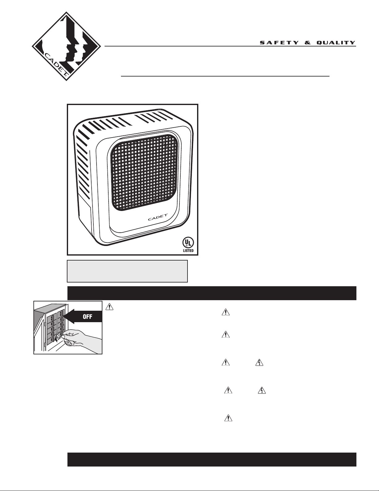
Turn the electrical power off at the electrical
panel board (circuit breaker or fuse box) and lock
or tag the panel board door to prevent someone from
turning on power while you are working on the
heater. Failure to do so could result in serious
electrical shock, burns, or possible death.
1. Read all instructions before using this heater.
2. Read all information labels. Verify that the electrical supply
wires are the same voltage as the heater.
3. All electrical work and materials must comply with the
National Electric Code (NEC), the Occupational Safety and
Health Act (OSHA), and all state and local codes.
4. If you need to install a new circuit or need additional wiring
information, consult a qualified electrician.
5. Protect electrical supply from kinks, sharp objects, oil,
grease, hot surfaces or chemicals.
6. Do not install heater below an electrical convenience
receptacle.
7. WARNING
Overheating or fire may occur. DO NOT place the heater
behind doors.
8. WARNING
Fire or explosion may occur. DO NOT place heater in any
area where combustible vapors, gases, liquids, or excessive
lint or dust are present.
9. WARNING
Burn Hazard. This heater is hot when in use. To avoid burns,
do not let bare skin touch hot surfaces. Use extreme caution
when any heater is used by or near children or invalids.
10. WARNING
Risk of Electrical Shock. Connect grounding lead to ground-
ing terminal provided. Keep all foreign objects out of
heater.
11. WARNING
Risk of Fire. Do not block heater. Heater must be kept clear
of all obstructions: maintain a 3 feet minimum clearance in
front, 12 inches on each side, and 6 inches from the rear.
Heater must be kept clean of lint, dirt and debris (See
Maintenance Instructions)
IMPORTANT INSTRUCTIONS
SAVE THESE INSTRUCTIONS
TEL: 360-693-2505 Fax: 360-694-8668 P.O. Box 1675 Vancouver, WA 98668-1675
Tools Required:
Appropriate Fasteners
Crescent Wrench
Phillips Screwdriver
Straight Screwdriver
Strain Relief Connector
Wire Strippers
OWNER’S GUIDE
The CEH Industrial Unit Heater
Models:
CEH-003M
CEH-003MB
CEH-003P
CEH-003PB
CEH-003RB
CEH-003R
CEH-003SB
CEH-005M
CEH-005MB
CEH-005P
CEH-005PB
CEH-005R
CEH-005SB
• Commercial grade high temperature
manual reset
• High mass, tubular element for longer life
• Fan delay eliminates cold draft on startup and
disperses residual heat on shutdown
• Rugged die formed construction for durability
• Wire single or three phase to suit the application
• Vertical or horizontal delivery
• 5 Year Warranty
Features & Benefits
• Recommended for elevations under 7500 feet

2
Installation Instructions
READ ALL INSTRUC-
TIONS AND SAFETY
INFORMATION.
WARNING!
When working
with electricity,
turn the electrical
power off at the
electrical panel
board and lock or
tag the circuit
breaker door.
Failure to do so
could result in
serious electrical
shock, burns, or
possible death.
WARNING!
Risk of Fire. Heaters
must be kept clean
of lint, dirt and
debris.
Failure to follow
warnings may
cause heater to
eject sparks, ignite
materials, or cause
electrical shock.
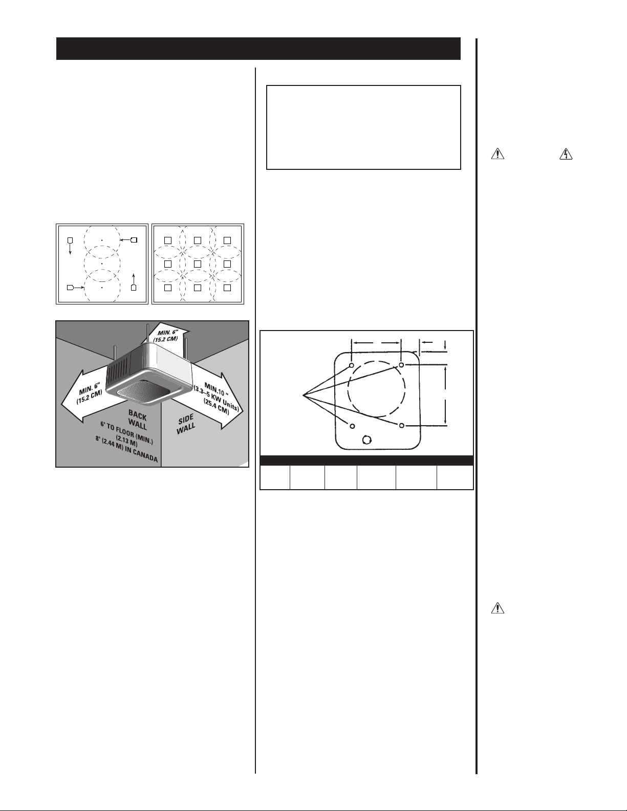
Horizontal Delivery
Heaters should be located so that the air streams
of the individual units "wipe" the exposed walls of
the building without blowing directly against the
wall. Recommended spacing between the units
is 12 feet. Locate heaters so their air streams are
not subjected to interference from columns,
partitions, machinery, etc.
(See Figure 1)
Figure 1.
PLACEMENT:Install the CEH unit heater vertically or horizontally. Brackets are also available for ceiling mount
or wall mount applications.
THERMOSTAT: A line voltage OR low voltage thermostat is required for operation. A Cadet wall thermostat is
recommended for ultimate control and comfort.
HORIZONTAL VERTICAL
MODEL DISCHARGE DISCHARGE
CEH-003 9' 10'
CEH-005 9' 10'
Figure 2. Horizontal mounting clearances with
optional bracket (CEK-M1).
MAXIMUM MOUNTING HEIGHT
(TO BOTTOM OF UNIT)
MIN. 6"
(15.2 CM)
MIN. 6"
(15.2 CM)
MIN. 10"
(3.3–5 KW Units)
(25.4 CM)
OPTIONAL
MOUNTING
BRACKET
1/2"
MOUNTING
BOLT
6
' TO FLOOR (MIN.
)
(2.13 M)
8' (2.44 M)
IN
CANADA
BACK
WALL
SIDE
WALL
CEILING
In an area where the air temperature will be maintained at less than 68˚F, the heater should be mounted in a postion that will not blow directly on people
working in the area.
A minimum clearance for each heater (both horizontal and vertical mount) is listed in Figure 2.
Please follow these recommendations to avoid
potential problems with the function and safety of the
heater.
Mounting the CEH Unit Heater
CAUTION:
THE CEILING OR WALL MOUNTING
STRUCTURE AND ANCHORING PROVISIONS
MUST BE OF SUFFICIENT STRENGTH TO
SUPPORT THE COMBINED WEIGHT OF THE
HEATER AND MOUNTING BRACKETS
Horizontal Discharge
(See Figure 2 for minimum clearances)
1. Mounting with rod from ceiling or superstructure:
(Figure 3)
a. Remove the four factory installed bolts from
the top of the unit and screw them into the
threaded holes in the back.
b. Install four 5/16-18 threaded rods in holes
and secure in place using lock (jam) nuts.
(Figure 3)
c. Attach the four mounting rods to the ceiling
or overhead structure and anchor securely.
2. Mounting with optional bolt-on ceiling
brackets:
(Figure 2)
a. Bolt mounting bracket on top of unit using
the four factory installed bolts.
b. Suspend the unit from ceiling or overhead
structure using a 1/2 inch threaded rod or
bolt, allowing a minimum 6 inches clearance
from the ceiling. Using lock (jam) nut, anchor
securely.
3. Mounting with optional wall hanger arm and
mounting bracket:
(See Parts List items #10 & #11)
a. Bolt mounting bracket on top of unit using
four factory installed bolts.
b. Attach the wall hanger arm to wall using
four 3/8 inch bolts or masonry fasteners.
c. Suspend the unit from hanger arm using
1/2 inch bolt. Place the rubber washer
provided between the mounting brackets.
General Safety Information
The ceiling or wall on which the heater is to be
mounted must be of adequate strength to support the
heater. Plaster or suspended ceilings will not support this type of heater. For greater stability, we
recommend the use of threaded rods.
Do not mount the heater where volatile liquids or
gases will be present or where it will be exposed
to rain or mist. All combustible materials should
be kept at least 3 feet away from front of the heater.
A
C
D
B
FRONT
5/16-18
Threaded
Mounting
Holes
UNIT KW ROD THREAD A B C D
3.3, 5.0 5/16-18 6" (15.2CM) 6.75" 4.04" 0.75"
Figure 3. Horizontal discharge rod spacing
MOUNTING ROD DIMENSIONS
3
Installation Instructions
WARNING!
Risk of Electrical
Shock. Turn off all
power at the electrical panel board supplying power to the
heater before doing
any electrical
wiring.
WARNING!
Overheating or fire
may occur. DO NOT
place the heater
behind doors.
Vertical Delivery
In buildings with high ceilings or bays, vertical
delivery unit heaters are recommended to produce
comfort in central areas. They are best used when
the perimeter heat loss is adequately controlled. In
combination with horizontally discharged units,
they aid in providing good air mixture (See Figure 4).
Vertical discharging units are mounted high above
machinery, assembly lines, etc.
In an application where only vertical discharging
units will be used, the air streams must overlap to
blanket outside walls and provide good heat distribution (See Figure 5).
Mounting the CEH Unit Heater
CAUTION:
THE CEILING OR WALL
MOUNTING STRUCTURE AND ANCHORING
PROVISIONS MUST BE OF SUFFICIENT
STRENGTH TO SUPPORT THE COMBINED
WEIGHT OF THE HEATER AND MOUNTING
BRACKETS
Vertical Discharge
(See Figure 6 for minimum clearances)
1. Install four 5/16-18 threaded rods into the
threaded holes in the back of the heater and
secure in place using lock (jam) nuts (Figure 7).
2. Attach the four mounting rods to ceiling or overhead structure and anchor securely.
NOTE: When mounting for vertical discharge,
position unit so that access door opens away
from nearest wall. This permits maximum
access to wiring compartment (Figures 2 & 6).
Figure 4.
Figure 5.
Figure 6. Ceiling mount. Vertical mounting clearances.
General Safety Information
The ceiling or wall on which the heater is to be
mounted must be of adequate strength to support
the heater. Plaster or suspended ceilings will not
support this type of heater. For greater stability, we
recommend the use of threaded rods.
Do not mount the heater where volatile liquids or
gases will be present or where it will be exposed to
rain or mist. All combustible materials should be
kept at least 3 feet away from front of the heater.
In an area where the air temperature will be maintained at less than 68˚F, the heater should be mounted in a position that will not blow directly on people
working in the area.
A minimum clearance for each heater (both horizontal and vertical mount) is listed in Figure 6.
Please follow these recommendations when
mounting to avoid potential problems with the function and safety of the heater.
E
H
G
F
5/16-18
Threaded
Mounting
Holes
BACK
Figure 7.
Vertical discharge rod spacing
UNIT KW
ROD THREAD
EF G H
3.3, 5.0 5/16-18 6" (15.2 CM) 9.63" (24.5 CM) 4.04" (10.3 CM) 2.10" (5.3 CM)
MOUNTING ROD DIMENSIONS
Operation and Maintenance
How to operate your heater
Turn your built-in or wall thermostat to the desired
setting. The heater will run for approximately
twenty seconds before the fan comes on. The
heater will then run until the thermostat setting is
reached. Fan will continue to run with elements
shut off for approximately seventy seconds and
then will shut off. This cycle will continue as needed based on thermostat setting. Do not use breaker panel or fuse box to control heater. Be sure
power to heater is constant all the time.
Maintenance
1. Shut off circuit breaker to heater.
2. Remove front diffuser grill or 3 of the center
louvers in front of fan area.
3. Using a compressor, blow air through the outer
cabinet louvers and finned element areas.
(Do not touch sharp surfaces on elements).
While holding fan blade (to avoid damage or
bending) carefully blow inside the fan motor
area.
4. Carefully wipe off the fan blade without
damaging or bending it.
5. Reinstall front diffuser or air vanes.
6. Restore power to heater.
 Loading...