

Cadence ORCAD PCB DESIGNER EXPLORER SIGNAL INTEGRITY TECHNOLOGY, OrCAD SIGNAL EXPLORER SIGNAL INTEGRITY TECHNOLOGY Datasheet
Page 1
DATASHEET
CADENCE ORCAD SIGNAL
EXPLORER SIGNAL INTEGRITY
TECHNOLOGY
Cadence® OrCAD® Signal Explorer helps engineers address
signal integrity issues throughout the design process—from the
conceptual schematic through placement and final routing. It
enables pre- and post-route topology exploration, signal analysis,
and validation, allowing designers to increase circuit reliability and
drive known-good interconnect requirements throughout the PCB
design flow.
Cadence OrCAD signal integrity
technology is available in the
following products:
• OrCAD Signal Explorer
Increasing design density, complexity, and
faster edge rates create a multitude of
signal integrity issues, which can lead to
time-consuming and frustrating simulatefix-simulate iterations and increased
production costs. Cadence OrCAD Signal
Explorer helps engineers address these
issues throughout the design process—
from the very beginning of the cycle
through placement and final routing.
The same signal integrity issues increase
the need for an integrated design flow
that enables designers to easily perform
post-layout extraction and verification of
complex PCB interconnect. An integrated
design and analysis environment eliminates
the need to translate design databases to
run simulations and analysis. Seamless integration with Cadence OrCAD PCB Editor
eliminates database conversion and possible translation issues. Engineers can now
perform signal integrity analysis or topology exploration at any stage of the design
cycle—when the board is partially or fully
placed, partially or fully routed, and even
when no netlist or PCB database exists.
Figure 1: O rCAD Signal Explorer ana lyzes and
validates topologies and interconnect to help
minimize potential SI-related issues for fewer respins and shorter lab debug time
Cadence OrCAD Signal Explorer provides
a SPICE-based simulation environment for
PCB signal integrity analysis. It consists of
the Tlsim simulation engine, the SigWave
waveform display, the device modeling
language (DML), translators from other
modeling formats, and a library model
editing/management subsystem.
Page 2
OrCAD Signal Explorer provides a SPICEbased simulation environment for PCB
signal integrity analysis. It consists of the
Tlsim simulation engine, the SigWave
waveform display, the device modeling
language (DML), translators from other
modeling formats, and a library model
editing/management subsystem.
BENEFITS
• Enablespre-andpost-layoutsignalintegrity analysis at any stage of the design
cycle, ensuring constraint adherence
• Allowsexploration,analysis,anddesign
of interconnect topologies to increase
circuit reliability, improve circuit performance, and reduce prototype re-spins
• Eliminatestheneedtotranslatedesign
databases to run simulations by importing extracted topologies directly from
OrCAD PCB Editor
• Providesaneasy-to-usemodelediting
environment that creates, manipulates, and validates a variety of models,
quickly improving model/simulation
performance
FEATURES
SIGXPLORER MODULE
OrCAD Signal Explorer provides an
electrical view of the physical interconnect
and a simulation cockpit for analysis of
critical high-speed signals. Users can
explore a net before schematics are
created by using the SigXplorer module
in a standalone mode. SigXplorer
provides various stripline and microstrip
models–lossy or lossless–to get started
with the exploration. Since OrCAD Signal
Explorer integrates seamlessly with OrCAD
PCB Editor, users can extract a net in the
pre-route or post-route stage right into
SigXplorer. Users can then quickly analyze
the signal using SPICE-based simulation.
SIGWAVE
The SigWave waveform display can
present simulation results in multiple
formats. The oscilloscope mode allows the
display of individual waveforms on and
off, and provides markers for on-screen
measurement. The logic analyzer mode
presents waveforms alongside one
another, so logic behavior and bus
transactions are easier to observe. The
spectrum analyzer mode displays signal
behavior in the frequency domain using
one of several FFT techniques. The eyediagram mode is useful for viewing
patterns in long simulation sequences.
SigWave also allows import of waveform
data directly from various standard test
equipment formats as well as from the
output formats of popular signal integrity
analysis tools.
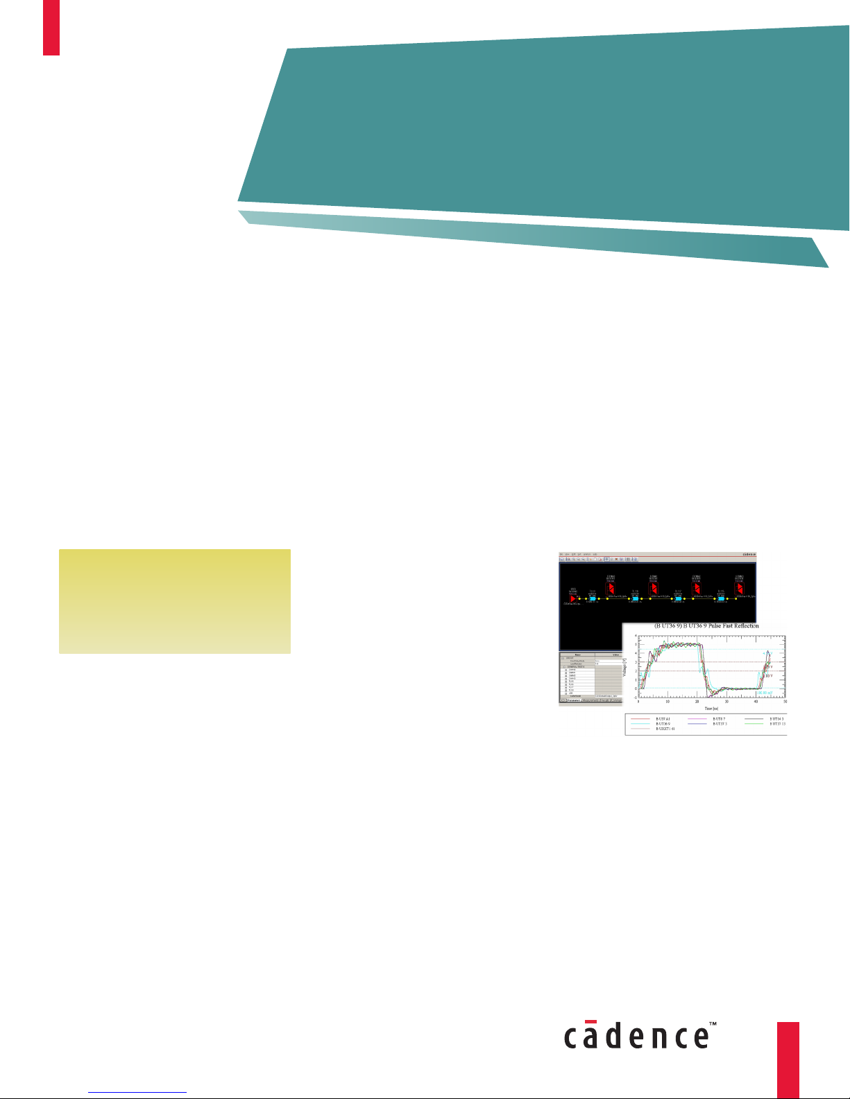
Figure 2: View and analyze simulation results in
SigWave
MODEL INTEGRITY
The Model Integrity module provides
an editing environment within OrCAD
Signal Explorer that allows the creation,
manipulation, and validation of models
quickly and easily. This module includes
a model browser and syntax checker
for models written in IBIS as well as for
advanced models written in DML.
OrCAD Signal Explorer accepts device
models from a variety of digital modeling
formats—including support for the
IBIS modeling standard—which means
models created by most semiconductor
manufacturers can be used. In addition,
OrCAD Signal Explorer provides DML,
a next-generation modeling language
for more complex devices. This flexible
macromodeling extension language
augments IBIS and allows state-of-the-art
I/O functionality to be modeled quickly
and accurately.
SPICE-BASED SIMULATION
ENVIRONMENT
The Tlsim simulation engine combines
the advantages of traditional SPICE-based
structural modeling with the speed of
behavioral analysis. It includes an IBIS-style
behavioral driver element that models
I/O behavior based on the V-I and V-T
data provided by behavioral modeling
techniques.
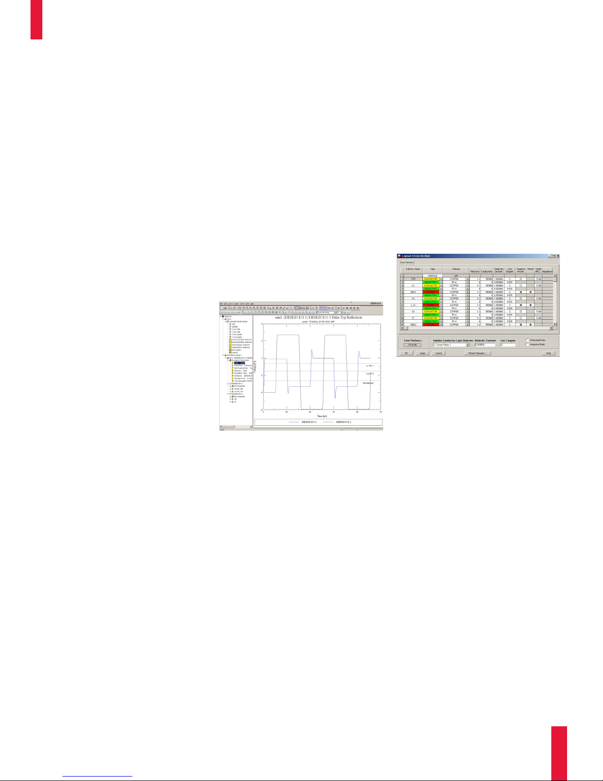
Figure 3: Users can change topologies or stack-up
information and perform quick, iterative tradeoffs
By combining both structural and
behavioral modeling techniques, Tlsim
enables accurate and efficient modeling
of complex device behavior. It includes a
lossy, frequency-dependent transmissionline model that accurately predicts the
distributed behavior of PCB traces up to
several gigahertz. An integrated electrical
field solver determines the electrical
characteristics of routed etch and creates
electrical models of PCB vias.
www.cadence.com
CADENCE OrCAD SIGNAL EXPLORER SIGNAL INTEGRITY TECHNOLOGY
2
Page 3

SALES, TECHNICAL
SUPPORT, AND TRAINING
The OrCAD product line is owned by
Cadence Design Systems, Inc., and
supported by a worldwide network of
Cadence Channel Partners.
For sales, technical support, or training, contact your local Cadence Channel
Partner. For a complete list of authorized
Cadence Channel Partners, visit
www.cadence.com/Alliances/
channel_partner
© 2008 Cadence Design Systems, Inc. All rights reserved. Cadence and OrCAD are registered trademarks and the Cadence logo is a trademark of Cadence
Design Systems, Inc. All others are properties of their respective holders.
20806/20458 11/08 MK/MVC/CS/PDF
 Loading...