

Page 1

HiFi 3 DSP
User’s Guide
Cadence Design Systems, Inc.
2566 Seely Ave.
San Jose, CA 95134
www.cadence.com
For Xtensa HiFi 3 DSP
Page 2

HiFi 3 DSP User's Guide
© 2007- 2017 Cadence Design Systems, Inc.
All Rights Reserved
This publication is provided “AS IS.” Cadence Design Systems, Inc. (hereafter “Cadence") does not make any warranty of any
kind, either expressed or implied, including, but not limited to, the implied warranties of merchantability and fitness for a
particular purpose. Information in this document is provided solely to enable system and software developers to use our
processors. Unless specifically set forth herein, there are no express or implied patent, copyright or any other intellectual
property rights or licenses granted hereunder to design or fabricate Cadence integrated circuits or integrated circuits based on
the information in this document. Cadence does not warrant that the contents of this publication, whether individually or as one
or more groups, meets your requirements or that the publication is error-free. This publication could include technical
inaccuracies or typographical errors. Changes may be made to the information herein, and these changes may be incorporated
in new editions of this publication.
Cadence, the Cadence logo, Allegro, Assura, Broadband Spice, CDNLIVE!, Celtic, Chipestimate.com, Conformal, Connections,
Denali, Diva, Dracula, Encounter, Flashpoint, FLIX, First Encounter, Incisive, Incyte, InstallScape, NanoRoute, NC-Verilog,
OrCAD, OSKit, Palladium, PowerForward, PowerSI, PSpice, Purespec, Puresuite, Quickcycles, SignalStorm, Sigrity, SKILL,
SoC Encounter, SourceLink, Spectre, Specman, Specman-Elite, SpeedBridge, Stars & Strikes, Tensilica, TripleCheck,
TurboXim, Vectra, Virtuoso, VoltageStorm, Xplorer, Xtensa, and Xtreme are either trademarks or registered trademarks of
Cadence Design Systems, Inc. in the United States and/or other jurisdictions.
OSCI, SystemC, Open SystemC, Open SystemC Initiative, and SystemC Initiative are registered trademarks of Open SystemC
Initiative, Inc. in the United States and other countries and are used with permission. All other trademarks are the property of
their respective holders.
PD-17-8530-10-06
RG-2017.7
Issue Date: 08/2017
ii CADENCE DESIGN SYSTEMS, INC.
Page 3

HiFi 3 DSP User's Guide
Contents
1. Introduction .................................................................................................................. 1
1.1 Purpose of this User Guide .................................................................................... 1
1.1.1 Conventions ........................................................................................................ 2
1.2 Installation Overview .............................................................................................. 2
1.3 HiFi 3 Architecture Overview .................................................................................. 2
1.4 Prefetching .............................................................................................................. 4
1.4.1 Software Prefetching .......................................................................................... 5
1.5 HiFi 3 Instruction Set Overview .............................................................................. 6
2. HiFi 3 Features ............................................................................................................. 7
2.1 Instruction Naming Conventions ........................................................................... 13
2.2 Fixed Point Values and Fixed Point Arithmetic .................................................... 14
2.2.1 Representation of Fixed Point Values .............................................................. 14
2.2.2 Arithmetic with Fixed Point Values ................................................................... 15
2.2.3 Other Fixed Point Representations .................................................................. 16
2.3 VLIW Slots and Formats ....................................................................................... 16
2.4 Load and Store Operations .................................................................................. 17
2.4.1 Aligning Loads and Stores ................................................................................ 17
2.4.2 Circular Buffer ................................................................................................... 20
2.4.3 Load and Store Naming Scheme ..................................................................... 22
2.4.4 Load Operations ............................................................................................... 25
2.4.5 Store Operations ............................................................................................... 38
2.5 Multiply and Accumulate Operations .................................................................... 48
2.5.1 24x24-bit Multiplication Operations .................................................................. 49
2.5.2 32x32-bit Multiplication Operations .................................................................. 54
2.5.3 32x16-bit Multiplication Operations .................................................................. 58
2.5.4 16x16-bit Multiplication Operations .................................................................. 64
2.5.5 16x16-bit Legacy Multiplication Operations ...................................................... 67
2.5.6 32x16-bit Legacy Multiplication Operations ...................................................... 68
2.5.7 HiFi 2 EP 32x24-bit Multiplication Operations .................................................. 71
2.6 Add, Subtract, and Compare Operations ............................................................. 72
2.7 Shift Operations .................................................................................................... 85
2.8 HiFi 2 Shift Operations ......................................................................................... 98
2.9 Normalization ...................................................................................................... 101
2.10 Divide Step Operation ........................................................................................ 102
2.11 Truncate, Round, Saturate, Convert, and Move Operations .............................. 102
2.12 Selection and Permutation Operations ............................................................... 119
2.13 Bitwise Logical Operations ................................................................................. 122
2.14 Bit Reversal ........................................................................................................ 123
2.15 Zero Operation .................................................................................................... 124
2.16 Optional Floating Point Unit ................................................................................ 124
CADENCE DESIGN SYSTEMS, INC. iii
Page 4

HiFi 3 DSP User's Guide
2.16.1 Notes on Not a Number (NaN) Propagation ............................................... 140
2.16.2 Floating Point Intrinsics .............................................................................. 140
2.17 Bitstream and Variable-Length Encode and Decode Instructions ...................... 146
2.17.1 Codebook Formats ..................................................................................... 156
3. Programming the DSP ............................................................................................. 159
3.1 Data Types ......................................................................................................... 160
3.1.1 Example C to Load, Store and Convert Fractions and Other Memory Types 164
3.1.2 Changing Types .............................................................................................. 165
3.2 Xtensa Xplorer Display Format Support ............................................................. 165
3.3 Programming Styles ........................................................................................... 166
3.4 Auto-Vectorization of Standard C/C++ ............................................................... 167
3.5 ITU-T/ETSI Intrinsics .......................................................................................... 170
3.6 Operator Overloading ......................................................................................... 171
3.6.1 Operator Overloading: Energy Calculation Example ...................................... 180
3.6.2 Operator Overloading: 32X16-bit Dot Product Example ................................ 183
3.7 Intrinsic-Based Programming ............................................................................. 183
3.8 HiFi 2 and HiFi Mini Code Portability .................................................................. 185
3.9 Important Compiler Switches .............................................................................. 186
4. Variable Length Encode and Decode ...................................................................... 187
4.1 Overview of Huffman Instructions ....................................................................... 187
4.1.1 Reading and Writing a Sequence of Raw Bits ............................................... 187
4.2 Encoding ............................................................................................................. 188
4.2.1 What Encoding a Symbol Looks Like ............................................................. 188
4.2.2 The Encoding Table Lookup Instruction Sequence ........................................ 189
4.3 Decoding ............................................................................................................. 189
4.3.1 The Decoding Table Lookup Instruction Sequence ....................................... 191
4.4 Examples for Encode/Decode ............................................................................ 191
5. Audio DSP Examples ............................................................................................... 193
5.1 Correlation/Convolution/FIR Coding Example .................................................... 193
5.2 Floating Point FIR Example ................................................................................ 196
5.3 FFT Example ...................................................................................................... 198
6. HiFi 3 NatureDSP Signal Library ............................................................................. 203
7. Implementation Methodology ................................................................................... 204
7.1 Configuring a HiFi 3 ............................................................................................ 204
7.2 XPG Estimation for HiFi 3 Size, Performance and Power.................................. 206
7.3 Basic HiFi 3 Characteristics ................................................................................ 206
7.4 Extending a HiFi 3 with User TIE ........................................................................ 207
7.4.1 Utilizing HiFi 3 Resources .............................................................................. 208
7.4.2 Name Space Restrictions for User TIE........................................................... 209
7.5 Optional Configuration Templates for HiFi 3 ..................................................... 210
7.6 Synthesis and Place-and-Route ......................................................................... 211
iv CADENCE DESIGN SYSTEMS, INC.
Page 5

HiFi 3 DSP User's Guide
Figures
Figure 1-1 HiFi 3 DSP Components ....................................................................................... 3
Figure 2-1 AE_DR Register .................................................................................................... 7
Figure 7-1 Configuring Hardware Prefetch ......................................................................... 205
Tables
Table 2-1 DSP Subsystem State Registers ........................................................................... 8
Table 2-2 Bitstream and Variable-length Encode/Decode Support Subsystem State
Registers .............................................................................................................. 8
Table 2-3 Circular Buffer Support State Registers ................................................................. 9
Table 2-4 Floating Point Support State Registers .................................................................. 9
Table 2-5 State Register Access Instructions ...................................................................... 10
Table 2-6 Operand Register Types ...................................................................................... 12
Table 2-7 Operand Immediate Types ................................................................................... 12
Table 2-8 Operation Mnemonics .......................................................................................... 13
Table 2-9 Circular Buffer States ........................................................................................... 20
Table 2-10 Load/Store Operation Sizes ............................................................................... 22
Table 2-11 Load/Store Operation Suffixes ........................................................................... 23
Table 2-12 Load Overview ................................................................................................... 25
Table 2-13 Store Overview ................................................................................................... 38
Table 2-14 AE_SEL16 Operation Values ........................................................................... 121
Table 2-15 CONST.S Immediates ...................................................................................... 131
Table 3-1 HiFi 3 C Types .................................................................................................... 161
Table 3-2 HiFi 3 Display Types .......................................................................................... 165
Table 3-3 HiFi 3 C/C++ Operators ..................................................................................... 171
Table 3-4 HiFi 3 C/C++ Floating Point Operators .............................................................. 177
Table 3-5 Legacy HiFi 2 C/C++ Operators ......................................................................... 178
CADENCE DESIGN SYSTEMS, INC. v
Page 6

HiFi 3 DSP User's Guide
Version
Changes
RG.7
The following changes (denoted with change bars) were made to this
document for the Cadence Tensilica RG-2017.7 release of the HiFi3 DSP:
Added information in section 2.4.2 that CBEGIN need not be less
than CEND
Updated information in Chapter 6 HiFi 3 NatureDSP Signal Library
RG.5
The following changes (denoted with change bars) were made to this
document for the Cadence Tensilica RG-2017.5 release of the HiFi3 DSP:
Enhanced the description of floating point operations
Corrected the intrinsic for AE_L16_IP
Corrected round instructions that were documented as returning
integer types instead of fractional types
Corrected AE_PKSR24 as returning a fractional type instead of an
integer type
RG.4
The following changes were made to this document for the Cadence Tensilica
RG-2016.4 release of the HiFi3 DSP:
Minor corrections to the (NaN) description
Enhanced conversions between variables of different types in section
3.1.
Clarified the usage restrictions for AE_DIV64
Clarified for converting HiFi 2 legacy types to and from HiFi 3 vector
types
Clarified rules on conversions from float to and from ae_int32x2
Corrected an inaccuracy in output type name for AE_MOVPA24x2
RG.3
Amended several instructions in Chapter 2, including:
Included required alignments
Amended the note for AE_MOVDA32X2 in Section2.11.
Updated Section 2.16.1.
Added information about conversions being applied to intrinsic
invocations in Section 3.1.
Updated Table 3-3 HiFi 3 C/C++ Operators.
Document Change History
vi CADENCE DESIGN SYSTEMS, INC.
Page 7

HiFi 3 DSP User's Guide
1.2
Minor clarifications re AE_SA16x4, as well as in Table 3-2 HiFi 3 Display
Types.
1.1
Added information regarding HiFi Mini in Section 3.8.
Corrected HiFi 3 Coprocessor number to 1 in Section 7.1
1.0
Initial customer release.
CADENCE DESIGN SYSTEMS, INC. vii
Page 8

HiFi 3 DSP User's Guide
viii CADENCE DESIGN SYSTEMS, INC.
Page 9

HiFi3 DSP User's Guide
1. Introduction
Cadence’s HiFi 3 DSP is a highly optimized audio processor geared for efficient execution of
audio and voice codecs, and pre- and post-processing modules. It goes beyond the two MAC,
two issue, HiFi 2/EP architecture with four multipliers, three VLIW slots, good support for
32x16-bit and 32x32-bit multiplication, a true 64-bit data path and native support for ITUT/ETSI intrinsics. There is an optional floating point unit available, providing for a
2-way SIMD, single-precision IEEE floating point MAC or ALU operation every cycle. The
extra resources provide for significant performance improvements compared to HiFi 2/EP,
particularly on pre/post-processing algorithms as well as voice codecs. The support for 32bit audio as well as ITU-T/ETSI intrinsics, including automatic vectorization, provides much
better performance on out-of-the-box C programs and voice algorithms.
HiFi 3 is backward compatible at the C/C++ source level with HiFi 2/EP. Any algorithm written
in C/C++, including all HiFi 2/EP packages from Cadence, can simply be recompiled on HiFi
3 to get modest performance improvements. For maximum performance, key kernels may
need to be retuned for the HiFi 3 architecture.
The HiFi 3 DSP is a configuration option that can be included with the Xtensa LX 4 (and later
versions) processor. All HiFi 3 DSP operations can be used as intrinsics in standard C/C++
applications. In addition, when compiling with automatic vectorization or with the –mcoproc
option, the compiler will automatically use HiFi 3 operations when compiling standard C code.
Cadence’s HiFi 3 DSP consists of two main components: a DSP subsystem and a subsystem
to assist with bitstream access, and variable-length (Huffman) encoding and decoding. These
are covered in detail in Chapter 2.
1.1 Purpose of this User Guide
This guide provides an overview of the HiFi 3 architecture and its instruction set. It will help
programmers using HiFi 3 by identifying some of the techniques that are commonly used to
optimize algorithms. It provides guidelines to achieve improved performance by using HiFi
3’s instructions, intrinsics, protos, and primitives. This guide also serves as a C/C++ usage
reference for the appropriate way to use HiFi 3 features in a C/C++ software development.
This guide will also assist Xtensa HiFi 3 users who wish to add additional instructions to the
HiFi 3 architecture.
To use this guide most effectively, a basic level of familiarity with the Xtensa software
development flow is highly recommended. For more details, see the Xtensa Software
Development Toolkit User’s Guide.
CADENCE DESIGN SYSTEMS, INC. 1
Page 10

HiFi 3 DSP User's Guide
1.1.1 Conventions
Throughout this guide, the symbol <xtensa_root> refers to the installation directory of a
user's Xtensa configuration. For example, <xtensa_root> might refer to the directory
\usr\xtensa\XtDevTools\install\builds\RF-2015.2-win32\<s1> if <s1> is the
name of your Xtensa configuration. In the examples in this guide, replace <xtensa_root>
with the installation directory of your Xtensa distribution.
1.2 Installation Overview
To install a HiFi 3 configuration, follow the same procedures described in the Xtensa
Development Tools Installation Guide. The HiFi 3 include files are in the following directories
and files:
<xtensa_root>/xtensa-elf/arch/include/xtensa/config/defs.h
<xtensa_root>/xtensa-elf/arch/include/xtensa/tie/xt_hifi3.h
For easier migration of existing HiFi codes, you can use either xt_hifi2.h or
_
xt
hifi3.h.
For floating point usage with the optional floating point unit, include the following file:
<xtensa_root>/xtensa-elf/arch/include/xtensa/tie/xt_FP.h
1.3 HiFi 3 Architecture Overview
The HiFi 3 DSP, a SIMD (single-instruction/multiple-data) processor, can work in parallel on
two 24/32-bit data items or four 16-bit data items. For example, it allows for one operation to
perform two 32-bit additions in parallel, with each addition occupying half of a 64-bit AE_DR
register. The HiFi 3 multipliers support multiplication of four 24-bit, or four 32x16-bit, or four
16x16-bit operands per cycle. They support two 32x32-bit multiplies per cycle. There are
operations for single, dual, and quad multiplication. Single or dual multiply operations can be
dual issued using VLIW instructions. Quad multiply operations cannot be issued together
with other multiplies. The HiFi 3 DSP can only be configured to use a little-endian byte
ordering.
With the optional floating point unit, HiFi 3 supports two IEEE-754 floating point MACs per
cycle.
In general, 16-bit support is geared towards efficient support of the ITU-T/ETSI intrinsic
model, while 32x16-bit and 24-bit support is provided for both integer and fixed-point
computation.
HiFi 3 is a VLIW architecture, supporting the execution of three operations in parallel. DSP
loads and stores, bitstream and Huffman operations, and core operations are available in
slot 0 of a VLIW instruction. DSP MAC and ALU operations are typically available in slot 1
2 CADENCE DESIGN SYSTEMS, INC.
Page 11

HiFi 3 DSP User's Guide
AR Base
Register File
Slot 2
Misc
Function
Slot 2
ALU MAC
Slot 2
Misc
Function
Slot 1
ALU
MAC
Slot 2
Slot 0
Variable
Length
Enc/Dec &
Bitstream
Misc
Function
Load /
Store
Unit
ALU
Register MUX
AE_DR
Register File
16 x 64 bits
32 bits
32 bits
Optional
FPU
and slot 2. The optional floating point operations are generally available in slot 1 of a twoslot format.
HiFi 3 supports either caches or local memories with the full flexibility provided by Xtensa
configurations. You can have either or both, and can make different choices for instruction
and data. Audio packages supplied by Cadence do not use DMA. Hence, most customers
either use caches or make local memories sufficiently large to cover desired applications.
The following diagram illustrates the main custom state, register file, and execution units
added to an Xtensa LX processor by the HiFi 3 DSP.
Figure 1-1 HiFi 3 DSP Components
The main hardware resources in the DSP subsystem are two 2-multiplier multiply/accumulate
units, an option for a 2-way SIMD single-precision IEEE floating point unit, a 16-entry register
file AE_DR to hold 64-bit, pairs of 32-bit or quads of 16-bit data items, an arithmetic/logic
unit, and a shift unit to operate on the AE_DR values. The multiplier units support two 32x32bit or 24x32-bit MACs or four 24x24, 16x32, or 16x16-bit MACs per cycle. The multiplies are
supported through single-instruction quad multiplies or through parallel-issued dual or single
multiply instructions.
The load/store unit is capable of loading or storing up to two 24-bit or 32-bit SIMD elements,
four 16-bit SIMD elements, or single elements up to 64 bits in size. 24-bit data can either be
contained inside 32-bit envelopes, or can be packed together into 24 bits of memory. Eight
packed elements can be loaded or stored in three instructions. The load/store unit supports
unaligned accesses, whereby a stream is first primed and afterwards 64 unaligned bits can
be loaded or stored in every cycle.
The DSP subsystem can be issued in several VLIW formats—two 3-slot VLIW formats
(ae_format and ae_format1), one 2-slot format (ae_format2), and one 2-slot mini format
(ae_mini0). The operations for the 3-slot VLIW formats can be issued in one of the three
slots. In each execution cycle, zero or one operation from each slot can be executed
independently according to the static bundling expressed in the machine code. For example,
load operations can execute concurrently with multiply/accumulate operations because loads
CADENCE DESIGN SYSTEMS, INC. 3
Page 12

HiFi 3 DSP User's Guide
are in ae_slot0 and multiply/accumulate operations are in ae_slot1 or ae_slot2_0. The two
slot format contains multiply instructions that produce more than one register result or use
extra operands as well as some legacy operations. For better code size, many operations
(not including integer or fixed point multiplies) are also available in single issue 16- and 24bit formats. Most floating point operations are available in the 24-bit formats.
1.4 Prefetching
HiFi 3 includes a prefetch option geared for systems with long memory latency. When the
HiFi 3 processor detects a positive stride-1 stream of cache misses (either data or
instruction), it can speculatively prefetch ahead up to four cache lines and place them in a
buffer close to the processor, or on the data side optionally into the L1 data cache (there is
no support for prefetching directly into the L1 instruction cache). In addition, you can manually
issue prefetch instructions.
Hardware prefetching is enabled by default in the reset code provided by Cadence with a low
setting. By default, on configurations that support it, data prefetches are placed into the L1
data cache. You can use the following HAL calls to explicitly disable prefetching or to increase
its aggressiveness in different sections of your code. With more aggressive prefetching, the
hardware will prefetch earlier when detecting a stream and will prefetch more lines ahead.
Assuming sufficient bus bandwidth, performance will improve with more aggressive prefetch,
but the system will require more bandwidth. Prefetching instructions and data can be
controlled separately.
#include <xtensa/hal.h>
int xthal_set_cache_prefetch(unsigned long long mode);
The value returned is not meant for direct use or interpretation; however, it is suitable for
passing to a subsequent call to xthal
_
set_cache
_
prefetch().
The mode parameter can be one of the following:
The value returned from a previous call to xthal
xthal_get_cache
One of the following constants, which apply to both instruction and data caches:
XTHAL
XTHAL
A bit-wise OR of two cache prefetch mode constants, one for the instruction cache:
XTHAL
XTHAL
XTHAL
_
prefetch()
_
PREFETCH
_
PREFETCH
_
ICACHE_PREFETCH
_
ICACHE_PREFETCH
_
ICACHE_PREFETCH
_
ENABLE(enable cache prefetch)
_
DISABLE(disable cache prefetch)
_
OFF(disable instruction cache prefetch)
_
LOW(enable, less aggressive prefetch)
_
MEDIUM(enable, midway aggressive
_
set_cache
_
prefetch() or
prefetch)
XTHAL
_
ICACHE_PREFETCH
_
HIGH(enable, more aggressive prefetch)
4 CADENCE DESIGN SYSTEMS, INC.
Page 13

HiFi 3 DSP User's Guide
XTHAL
_
ICACHE
_
PREFETCH(n) (explicitly set the InstCtl field of the
PREFCTL register to 0..15. See the Prefetch Architectural Additions
section of the Prefetch Unit Option chapter in the Xtensa
Microprocessor Data Book for details.
A bit-wise OR of two cache prefetch mode constants, one for the data cache:
XTHAL
XTHAL
XTHAL
_
DCACHE_PREFETCH
_
DCACHE_PREFETCH
_
DCACHE_PREFETCH
_
OFF (disable data cache prefetch)
_
LOW (enable, less aggressive prefetch)
_
MEDIUM (enable, midway aggressive
prefetch)
XTHAL
XTHAL
_
DCACHE_PREFETCH
_
DCACHE
_
PREFETCH(n) (explicitly set the DataCtl field of the
_
HIGH (enable, more aggressive prefetch)
PREFCTL register to 0..15. See the Prefetch Architectural Additions
section of the Prefetch Unit Option chapter in the Xtensa
Microprocessor Data Book for details.
XTHAL
_
DCACHE_PREFETCH_L1
_
OFF (prefetch data to prefetch buffers
only)
XTHAL
_
DCACHE_PREFETCH
_
L1 (on configurations that support it,
prefetch directly to L1 data cache)
For easier simulation, prefetching can also be disabled in the simulator using the xt-run -
-prefetch=0 flag. Disabling prefetching from the simulation command line will override any
HAL calls.
1.4.1 Software Prefetching
Prefetching can also be individually controlled via software using the following GCC
extension:
__builtin_prefetch(addr);
Software prefetches can be used for either data or instructions. They can be used in addition
to, or instead of hardware prefetching. If hardware prefetching is disabled, the software
prefetches are still enabled.
For configurations that do not prefetch into the cache, but instead use a small, 8- to 16-entry
buffer outside of the cache, you must be careful not to prefetch too far ahead. Otherwise, the
data will be overwritten before it is needed by the processor.
Consider a simple example that does an energy calculation. You might choose to place a
few explicit prefetch instructions before the loop to seed the hardware prefetcher. Otherwise,
depending on the mode, the hardware prefetch might delay prefetching until after the second
miss.
__builtin_prefetch(&ap[0]);
__builtin_prefetch(&ap[XCHAL_DCACHE_LINESIZE]);
__builtin_prefetch(&ap[2*XCHAL_DCACHE_LINESIZE]);
CADENCE DESIGN SYSTEMS, INC. 5
Page 14

HiFi 3 DSP User's Guide
for (i=0; i<n; i++) {
sum += ap[i]*ap[i];
}
You might also want to put prefetch instructions directly inside the loop. Doing so allows you
to prefetch more aggressively than the hardware prefetcher and allows you to prefetch
patterns other than the stride-1 references that are detected by the hardware prefetcher. On
the other hand, placing prefetch instructions inside the loop incurs instruction overhead
whether or not the loop actually suffers from cache misses.
In general, given the effectiveness of the hardware prefetcher, software prefetches should
be used judiciously. Carefully compare performance between using and not using software
prefetching on a loop-by-loop basis.
1.5 HiFi 3 Instruction Set Overview
The HiFi 3 DSP is built on the baseline Xtensa RISC architecture, which implements a rich
set of generic instructions optimized for efficient embedded processing. The power of HiFi 3
comes from a comprehensive DSP and audio instruction set. A wide variety of load/store
operations support multiple addressing modes, with support for 16/24/32-bit scalar and
vector data types together with 56/64-bit scalar. Vector data management is supported with
select operations and shifting.
Multiply operations include 32x32-bit, 32x24-bit, 24x24-bit, 32x16-bit and 16x16-bit. Multiply
operations come in fixed-point and integer variants. They come in high precision and low
precision variants. High-precision multiplies utilize a 64-bit accumulator. Since an
accumulator can only hold one result, HiFi 3 supports dual multiplies where the results of two
multiplies are added or subtracted together before being added into the accumulator. For
example, a single operation might compute the following operation where H and L refer to
the high bits or low bits respectively of an operand.
acc = acc – d0.L*d1.L + d0.H*d1.H.
Low-precision multiplies accumulate in 32-bits. Since each register can hold two 32-bit
accumulators, these instructions can perform two independent SIMD multiplies.
A set of bitstream and variable length instructions allow for efficient access of serial
bitstreams, including Huffman encode and decode.
The optional floating point unit supports 2-way SIMD units of IEEE-754 single precision
floating point operations. Refer to the Xtensa Instruction Set Architecture (ISA) Reference
Manual for more details about the core single precision floating point support, on which the
2-way SIMD units are based.
6 CADENCE DESIGN SYSTEMS, INC.
Page 15
HiFi 3 DSP User's Guide
H
L
2
1
0
31 … 0
31 … 0
15 … 0
15 … 0
15 … 0
15 … 0
63 … 0
3
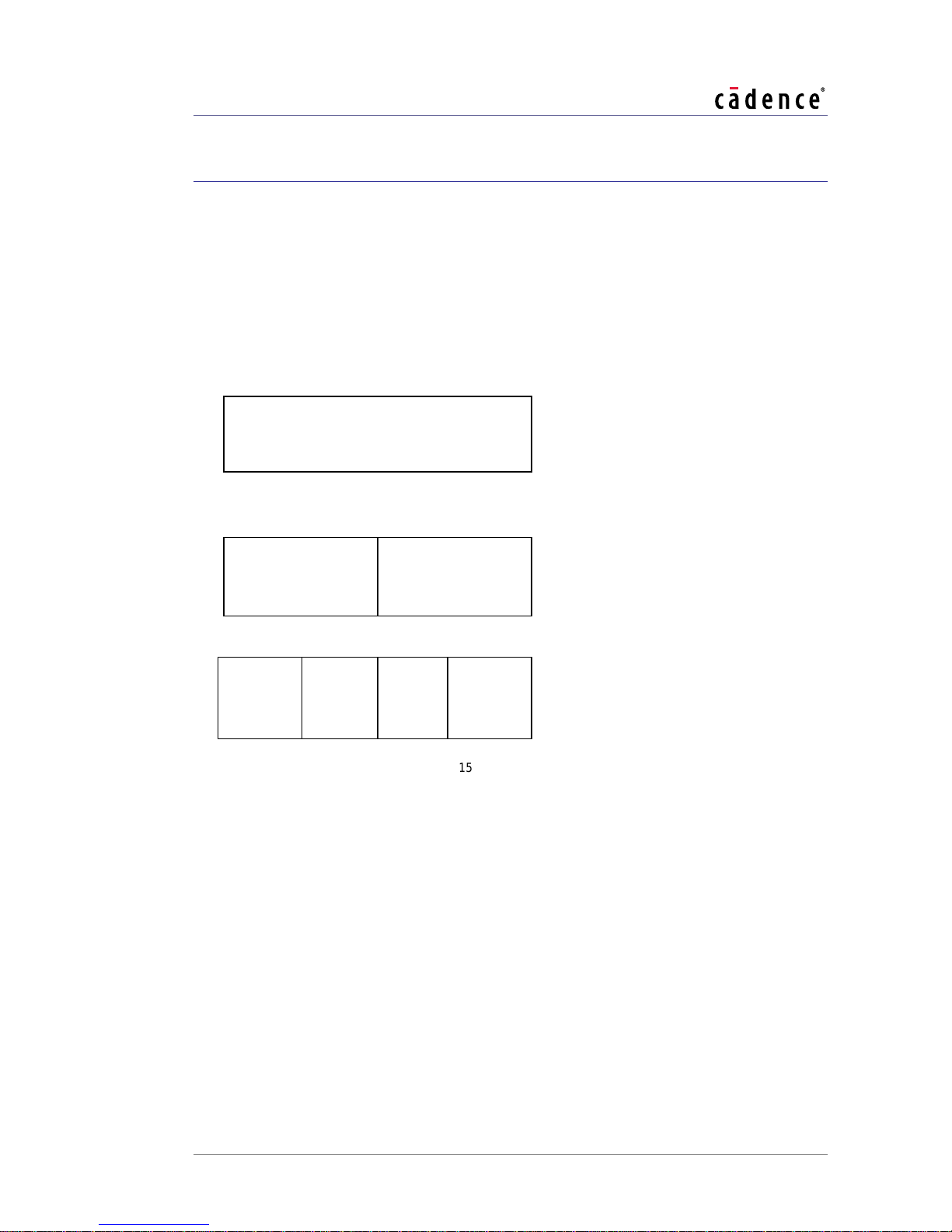
2. HiFi 3 Features
The HiFi 3 DSP contains a 16-entry, 64-bit register file, AE_DR. Each register can hold one
or two, 24 or 32-bit operands, one or four 16-bit operands or one 56- or 64-bit operand as
shown in Figure 2-1. 24-bit and 56-bit operands are sign extended to fill their 32- or 64-bit
container. The separate halves or quarters of the register are always separate data items.
For example, if you shift a 32-bit element to the left, the L element does not spill over into the
high element.
Figure 2-1 AE_DR Register
When a register is stored to memory, the high half of the register is always stored in the
lower memory address. This enables the same source code to work on all configurations,
including big-endian HiFi2 cores. Operations that access individual 24- or 32-bit elements
of AE_DR registers refer to the elements with selectors L and H in the mnemonics.
Operations that access individual 16-bit elements refer to the elements with sectors 3, 2, 1
and 0 in the mnemonics.
For legacy HiFi 2/EP instructions, a 32-bit data item might occupy the middle of an entire
AE_DR register and a 16-bit data item might occupy the middle of a 32-bit half register.
When using such legacy instructions, a register holds half as many elements, hence the
instruction exploits less parallelism. Such instructions should only be used in legacy code.
CADENCE DESIGN SYSTEMS, INC. 7
Page 16

HiFi 3 DSP User's Guide
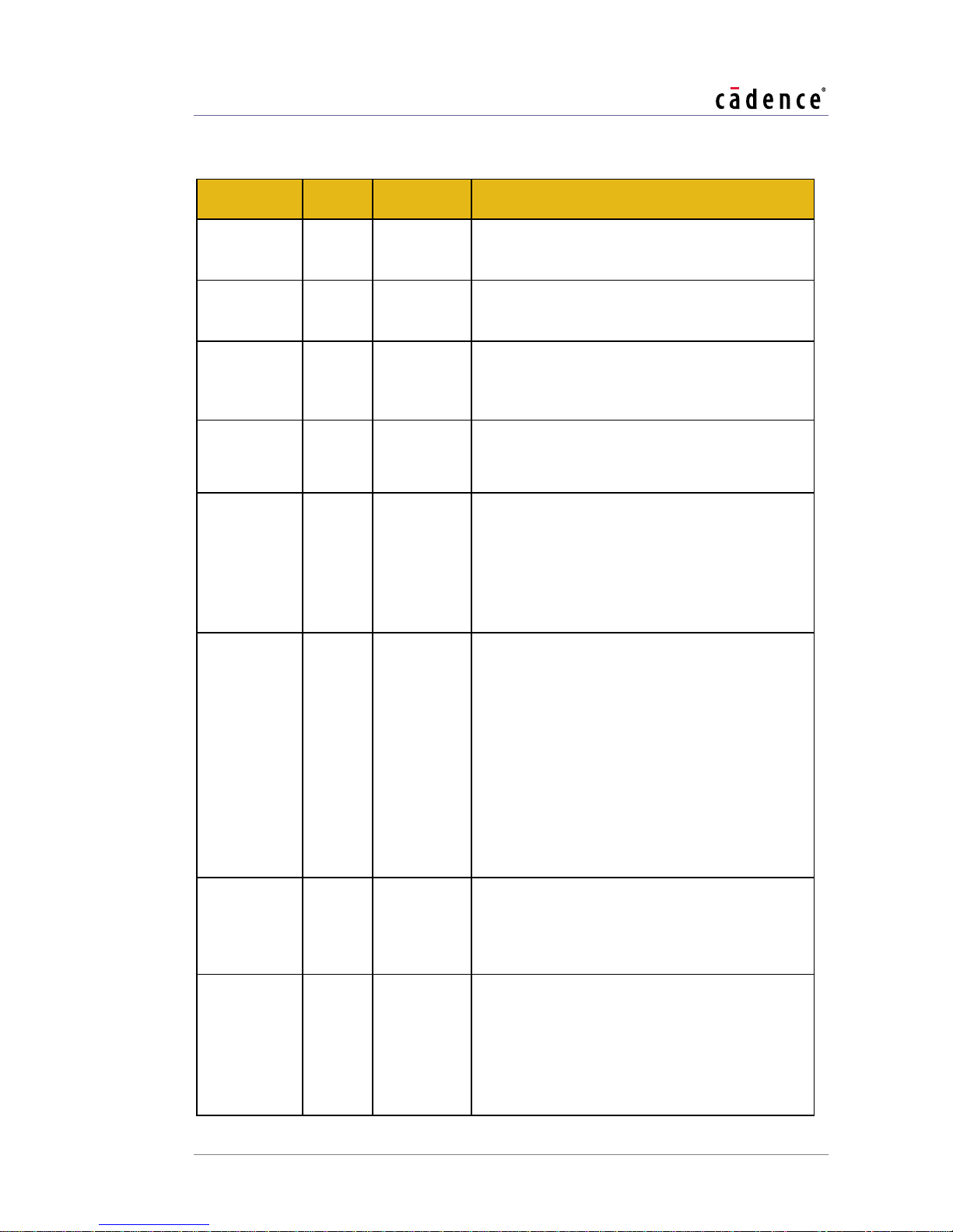
State Register
Bit Size
Description
AE_OVERFLOW
1
Indicates whether any arithmetic operation has saturated
since the time when AE_OVERFLOW was last reset to zero.
AE_SAR
7
Contains the shift amount for various DSP shift operations.
State Register
Bit
Size
Description
AE_BITHEAD
32
Contains the bits at the head of the bitstream. The high half
has the current 16 bits and the low half has the next 16 bits.
Only the high half is used for output bitstreams.
AE_BITPTR
4
Offset within the 16 most-significant bits of the bitstream
head. For an input bitstream, this value signifies the number
of most significant bits of AE_BITHEAD that have been
consumed already by the application. For an output
bitstream, this value signifies the number of most significant
bits of AE_BITHEAD that have already been initialized.
AE_BITSUSED
4
Contains the number of bits consumed or produced in the
last table lookup by a variable-length encode/decode
instruction. This value is coded in binary, with the exception
that all zeroes are interpreted as the value 16.
AE_TABLESIZE
4
Contains one less than the base-2 logarithm of the current
decoding table size for variable-length decode. 0
corresponds to a 2-entry table; 15 corresponds to a 65536entry table.
AE_FIRST_TS
4
Contains the correct value of AE_TABLESIZE for the first
level in the lookup-table hierarchy. This state is an
optimization so that no AE_VLDSHT instruction is needed
between consecutive decoding operations using the same
codebook.
AE_NEXTOFFSET
27
This state is used for three different things.
In variable-length decode: Before an AE_VLDL16T or
AE_VLDL32T instruction, AE_NEXTOFSET is the index
HiFi 3 supports a 4-entry, 64-bit alignment register, AE_VALIGN. Using this register allows
the hardware to load or store a SIMD stream that is not 64-bit aligned at a rate of 64-bits
per cycle. It also allows 24-bit data to be packed densely into 24-bit containers. These
mechanisms are described in more detail In Section 2.4.1.
Table 2-1 lists the the TIE state registers in the HiFi 3 DSP.
Table 2-1 DSP Subsystem State Registers
The state registers listed in Table 2-2 pertain to the bitstream and variable-length
encode/decode support subsystem of the HiFi 3 DSP. Programmers generally will not need
to concern themselves with the details of how each of these state registers is used by the
instructions. However, the state registers (understandable for those familiar with the variablelength encode/decode instructions) are documented here for completeness.
Table 2-2 Bitstream and Variable-length Encode/Decode Support Subsystem State Registers
8 CADENCE DESIGN SYSTEMS, INC.
Page 17

HiFi 3 DSP User's Guide
State Register
Bit
Size
Description
of the table entry corresponding to the current bitstream
prefix to look up.
After an AE_VLDL16T or AE_VLDL32T instruction,
AE_NEXTOFFSET is the offset of the base of the next
decoding lookup table.
In variable-length encode: After an AE_VLEL16T or
AE_VLEL32T instruction, the low bits of
AE_NEXTOFFSET hold the codeword bits produced by
the most recent lookup.
AE_SEARCHDONE
1
This state tells the AE_VLDL16C instruction to prepare
AE_NEXTOFFSET (using AE_FIRST_TS) for a fresh
decoding search starting with the first table in the decoding
hierarchy. This state is an optimization so that no
AE_VLDSHT instruction is needed between consecutive
decoding operations using the same codebook.
State Register
Bit
Size
Description
AE_CBEGIN0
32
Contains the start address of the circular buffer.
AE_CEND0
32
Contains the end address of the circular buffer.
AE_CWRAP
1
Indicates whether any circular buffer operation has wrapped
around since the time when AE_CWRAP was last reset to zero.
State Register
Bit Size
Description
RoundMode
2
Control the rounding mode of floating point operations. A
value of 0 rounds to nearest, a value of 1 rounds toward
0, a value of 2 rounds towards infinite and a value of 3
rounds toward negative infinite.
InvalidFlag
1
Invalid exception flag.
DivZeroFlag
1
Divide-by-zero flag.
OverflowFlag
1
Overflow exception flag.
UnderflowFlag
1
Underflow exception flag.
InexactFlag
1
Inexact exception flag.
The following state registers pertain to the circular buffer support and are shared between
the DSP subsystem and the bitstream and variable-length encode/decode support
subsystem of the DSP.
Table 2-3 Circular Buffer Support State Registers
The following state registers pertain to the optional floating point support.
Table 2-4 Floating Point Support State Registers
CADENCE DESIGN SYSTEMS, INC. 9
Page 18

HiFi 3 DSP User's Guide
Instruction
Intrinsic
Description
RUR.AE_OVERFLOW
RUR_AE_OVERFLOW,
RAE_OVERFLOW
Read state register
AE_OVERFLOW
RUR.AE_SAR
RUR_AE_SAR,
RAE_SAR
Read state register
AE_SAR
RUR.AE_TABLESIZE
RUR_AE_TABLESIZE,
RAE_TABLESIZE
Read state register
AE_TABLESIZE
RUR.AE_FIRST_TS
RUR_AE_FIRST_TS,
RAE_FIRST_TS
Read state register
AE_FIRST_TS
RUR.AE_BITHEAD
RUR_AE_BITHEAD,
RAE_BITHEAD
Read state register
AE_BITHEAD
RUR.AE_BITSUSED
RUR_AE_BITSUSED,
RAE_BITSUSED
Read state register
AE_BITSUSED
The TIE state registers are grouped as follows into six user registers for the purposes of
efficient save and restore operations:
user_register AE_OVF_SAR 240 { AE_SAR[6],
AE_OVERFLOW[0],
AE_SAR[5:0] }
user_register AE_BITHEAD 241 AE_BITHEAD[31:0]
user_register AE_TS_FTS_BU_BP 242 { AE_TABLESIZE[3:0],
AE_FIRST_TS[3:0],
AE_BITSUSED[3:0],
AE_BITPTR[3:0] }
user_register AE_CW_SD_NO 243 { AE_CWRAP[0],
AE_SEARCHDONE[0],
AE_NEXTOFFSET[26:0] }
user_register AE_CBEGIN0 246 AE_CBEGIN0[31:0]
user_register AE_CEND0 247 AE
_
CEND0[31:0]
With the floating point option, use the following user register to control and detect rounding
and exception behavior. Refer to Chapter 4 of the Xtensa Instruction Set Architecture (ISA)
Reference Manual for more details.
user_register FCR
_
FSR
{RoundMode,InvalidFlag,DivZeroFlag,OverflowFlag,UnderflowFlag,InexactFlag}
In addition to specialized instructions sequences used to save and restore entire user
registers efficiently from memory, instructions are provided to read and write individual
state registers. Both types are listed in Table 2-5.
Table 2-5 State Register Access Instructions
10 CADENCE DESIGN SYSTEMS, INC.
Page 19

HiFi 3 DSP User's Guide
Instruction
Intrinsic
Description
RUR.AE_BITPTR
RUR_AE_BITPTR,
RAE_BITPTR
Read state register
AE_BITPTR
RUR.AE_SEARCHDONE
RUR_AE_SEARCHDONE,
RAE_SEARCHDONE
Read state register
AE_SEARCHDONE
RUR.AE_NEXTOFFSET
RUR_AE_NEXTOFFSET,
RAE_NEXTOFFSET
Read state register
AE_NEXTOFFSET
RUR.AE_CBEGIN0
RUR_AE_CBEGIN0,
RAE_CBEGIN0,
AE_GETBEGIN
Read state register
AE_CBEGIN0
.
AE_GETCBEGIN0
returns a
void *
value.
RUR.AE_CEND0
RUR_AE_CEND0,
RAE_CEND0,
AE_GETCEND0
Read state register
AE_CEND0. AE_GETCEND0
returns a
void *
value.
RUR.AE_CWRAP
RUR_AE_CWRAP,
RAE_CWRAP
Read state register
AE_CWRAP
RUR.FCR
RUR_FCR
Read register FCR containing state RoundMode
RUR.FSR
RUR_FSR
Read register FSR corresponding to state
registers InvalidFlag, DivZeroFlag,
OverflowFlag, and UnderflowFlag
AE_MOVVFCRFSR
AE_MOVVFCRFSR
Copy user register FCR_FSR into a vector
register which can be stored to memory.
WUR.AE_OVERFLOW
WUR_AE_OVERFLOW,
WAE_OVERFLOW
Write state register
AE_OVERFLOW
WUR.AE_SAR
WUR_AE_SAR,
WAE_SAR
Write state register
AE_SAR
WUR.AE_TABLESIZE
WUR_AE_TABLESIZE,
WAE_TABLESIZE
Write state register
AE_TABLESIZE
WUR.AE_FIRST_TS
WUR_AE_FIRST_TS,
WAE_FIRST_TS
Write state register
AE_FIRST_TS
WUR.AE_BITHEAD
WUR_AE_BITHEAD,
WAE_BITHEAD
Write state register
AE_BITHEAD
WUR.AE_BITSUSED
WUR_AE_BITSUSED,
WAE_BITSUSED
Write state register
AE_BITSUSED
WUR.AE_BITPTR
WUR_AE_BITPTR,
WAE_BITPTR
Write state register
AE_BITPTR
WUR.AE_SEARCHDONE
WUR_AE_SEARCHDONE,
WAE_SEARCHDONE
Write state register
AE_SEARCHDONE
WUR.AE_NEXTOFFSET
WUR_AE_NEXTOFFSET,
WAE_NEXTOFFSET
Write state register
AE_NEXTOFFSET
WUR.AE_CBEGIN0
WUR_AE_CBEGIN0,
WAE_CBEGIN0,
AE_SETCBEGIN0
Write state register
AE_CBEGIN0
.
AE_SETCBEGIN0
take a
void *
value.
CADENCE DESIGN SYSTEMS, INC. 11
Page 20

HiFi 3 DSP User's Guide
Instruction
Intrinsic
Description
WUR.AE_CEND0
WUR_AE_CEND0,
WAE_CEND0,
AE_SETCEND0
Write state register
AE_CEND0 AE_SETCEND0
take a
void *
value.
WUR.AE_CWRAP
WUR_AE_CWRAP,
WAE_CWRAP
Write state register
AE_CWRAP
WUR.FCR
WUR_FCR
Write register FCR containing state RoundMode
WUR.FSR
WUR_FSR
Write register FSR corresponding to state
registers InvalidFlag, DivZeroFlag,
OverflowFlag, and UnderflowFlag
AE_MOVFCRFSRV
AE_MOVFCRFSRV
Set user register FCR_FSR from a vector
register which can be loaded from memory.
Placeholder
Register file
Legal values
Example
A, ah, al, a0, a1, ax
AR
a0 – a15
a3
q, q0, q1, d, d0, d1, dh, dl
AE_DR
aed0 – aed15
aed2
b
BR
b0 – b15
b3
bhl
BR2
b0 – b14 (even)
b0
b3210
BR4
b0-b16 (multiple of 4)
b0
u
AE_VALIGN
u0-u3
u0
Placeholder
Value Range
Stride
i16
-16..14
2
i16pos
0..14
2
i32
-32..28
4
i32pos
0..28
4
i64
-64..56
8
i64pos
0..56
8
i
Operation-dependent
1
In the operation descriptions in Sections 2.4 through 2.17, each mnemonic is listed with
assembly syntax showing placeholders for its operands. The register files of the operands
are implied by the placeholders, as in Table 2-6.
Table 2-6 Operand Register Types
Each operation description is annotated with the name(s) of the slot(s) where that operation
can be issued. Each operation description is also annotated with the C syntax showing the
intrinsic name and prototype for the operation. A discussion of using C data types and
intrinsics to program the HiFi 3 DSP is included in Chapter 3.
12 CADENCE DESIGN SYSTEMS, INC.
Table 2-7 Operand Immediate Types
Page 21

HiFi 3 DSP User's Guide
Mnemonic
Meaning
ASYM
Denotes asymmetric rounding (e.g., AE_ROUND32X2F64SASYM)
F
Denotes fractional arithmetic (e.g., AE_MULZAAFD24.HH.LL) or the value False in
a conditional move (e.g., AE_MOVF64).
H
and L
Combinations of H and L are used to refer to halves of registers (e.g.,
AE_MULZAAFD24.HH.LL).
0,1,2,3
Combinations of 0, 1, 2 and 3 are used to refer to quarters of registers (e.g.
AE_MULF32X16.L0)
I
Denotes use of an immediate operand (e.g., AE_SRAIP32)
S
Denotes saturating arithmetic (e.g., AE_MULF32S.LL) or the use of the AE_SAR
state register as a shift amount (e.g., AE_SRASP32), depending on the context
SYM
Denotes symmetric rounding (e.g., AE_ROUND32X2F64SSYM)
T
Denotes the value True in a conditional move (e.g., AE_MOVT64)
U
Denotes unsigned arithmetic (e.g., AE_MULS32U.LL)
X
Denotes use of an index register in an address computation (e.g., AE_L64.XP)
X2
Denotes a 2-way SIMD operation in contexts (e.g., AE_L32X2.I) where scalar
operations are also available
X4
Denotes a four-way SIMD operation (e.g., AE_L16X4.XC)
All HiFi 2 C types and intrinsics are available in HiFi 3 to ensure C/C++ source code
portability. Notes on HiFi 2 code portability and matching intrinsics are included in the
operation description for the relevant operations as well as in Chapter 3.
2.1 Instruction Naming Conventions
All HiFi 3 DSP operation mnemonics begin with the string AE_ to avoid colliding with any
other space of names. The optional floating point instructions use the standard Xtensa
floating point intrinsic names that add an XT_ prefix to the operation name and replace the
.S with _S.
Following the AE_ prefix, each mnemonic has a string of one or more characters signifying
the type of operation such as load, shift, add, etc. For example, AE_L is the prefix denoting
DSP loads.
The remaining portion of each operation mnemonic typically includes reminders of various
aspects of the operation’s details. Multiplies and loads and stores have more regular naming
conventions that are described in their respective sections.
Table 2-8 Operation Mnemonics
CADENCE DESIGN SYSTEMS, INC. 13
Page 22

HiFi 3 DSP User's Guide
Signed Integer (1 bit)
Fractional (23 bits)
0
100 0000 0000 0000 0000 0000
0x0
0x40 0000
Signed Integer (17 bit)
Fractional (47 bits)
1 1111 1111 1111 1110
100 0000 0000 0000 0000 0000 0000 0000 0000 0000 0000 0000
0x1fffe
0x4000 0000 0000
2.2 Fixed Point Values and Fixed Point
Arithmetic
The HiFi 3 DSP contains instructions for implementing fixed point arithmetic. This section
describes the representation and interpretation of fixed point values as well as some
operations on fixed-point values.
2.2.1 Representation of Fixed Point Values
A fixed point data type m.n contains a sign bit, some number of bits m-1, to the left of the
decimal and some number of bits n, to the right of the decimal. When expressed as a binary
value and stored into a register file, the least significant n bits are the fractional part, and
the most significant m bits are the integer part expressed as a signed 2’s complement
number. If the binary value is interpreted as a 2’s complement signed integer, converting
from the binary value to a fixed point number requires dividing the integer by 2n.
Thus, for example, the 24-bit 1.23 number 0.5 is represented as 0x400000.
And the 64-bit 17.47 number -1.5 is represented as (-2 + 0.5 = 0xff 4000 0000 0000)
14 CADENCE DESIGN SYSTEMS, INC.
Page 23

HiFi 3 DSP User's Guide
HiFi 3 fractional instructions use fractional operations on 1.15, 1.23, 9.23, 1.31, 17.47, and
1.63, described in more details as follows.
1.15 16-bit fixed point data type with 1 sign bit and 15 bits to the right of the
decimal. The largest positive value 0x7fff is interpreted as 1.0 – 2
-15
. The smallest
negative value 0x8000 is interpreted as -1.0. The value 0 is interpreted as 0.0.
9.23 32-bit fixed point data type with a 9-bit integer and 23 bits to the right of the
decimal. The largest positive value 0x7fffffff is interpreted as 256.0 – 2
-23
. The
smallest negative value 0x80000000 is interpreted as -256.0. The value 0 is
interpreted as 0.0.
1.23 24-bit fixed point data type with 1 sign bit and 23 bits to the right of the
decimal. The largest positive value 0x7fffff is interpreted as 1.0 – 2
-23
. The smallest
negative value 0x800000 is interpreted as -1.0. The value 0 is interpreted as 0.0.
Since register halves hold 32 bits, not 24 bits, typical 24-bit fractional variables are
9.23. However, 24-bit fixed-point multiply instructions ignore the upper 8-bits,
thereby treating them as 1.23.
1.31 32-bit fixed point data type with 1 sign bit and 31 bits to the right of the
decimal. The largest positive value 0x7fffffff is interpreted as 1.0 – 2
-31
. The
smallest negative value 0x80000000 is interpreted as -1.0. The value 0 is
interpreted as 0.0.
17.47 64-bit fixed point data type with a 17-bit integer and 47 bits to the right of
the decimal. The largest positive value 0x7fff ffff ffff ffff is interpreted as 65536.0 –
-47
2
. The smallest negative value 0x8000 0000 0000 0000 is interpreted as -
65536.0. The value 0 is interpreted as 0.0.
1.63 64-bit fixed point data type with 1 sign bit and 63 bits to the right of the
decimal. The largest positive value 0x7fff ffff is interpreted as 1.0 – 2
-63
. The
smallest negative value 0x8000 0000 0000 0000 is interpreted as -1.0. The value 0
is interpreted as 0.0.
2.2.2 Arithmetic with Fixed Point Values
When multiplying fixed point numbers m.n0 * m.n1, with a standard signed integer multiplier,
the natural result of the multiple will be an m.n data type where n = n0+n1 and m = m0+m1.
For example, multiplying a 1.23 typed variable by a 1.23 typed variable generates a 2.46
typed variable. Since HiFi 3 supports the 17.47 data type, the fixed point multiply instructions
shift the 2.46 result to the left by 1 bit and then sign extends it by 15 bits. In general, highprecision fixed-point multiplications shift their results to the left by 1 bit.
HiFi 3 contains both saturating and non-saturating instructions. Overflowing the supplied
guard bits with a non-saturating instruction is a program error that will cause the result to
wrap around. For saturating operations, the processor also sets the overflow state, which
can later be checked programmatically. In the instruction descriptions that follow, it is
explicitly stated if an operation saturates.
CADENCE DESIGN SYSTEMS, INC. 15
Page 24

HiFi 3 DSP User's Guide
2.2.3 Other Fixed Point Representations
Programmers are free to use fixed-point representations other than the ones listed in Section
2.2.2. Most HiFi 3 operations are independent of fixed-point representation; e.g., a fixed point
add is equivalent to an integer one. Even for multiplies, the multiply instructions are
compatible with any representations that expect the result to be shifted left by one bit. So, if
the input data is actually a 2.22 data type rather than a 1.23 data type, the 24-bit fixed point
multiply instructions will correctly produce an 11.45 typed variable. The programmer is
responsible for knowing what type of data is in what variables, and if manual conversions are
needed, you can always use shift instructions.
2.3 VLIW Slots and Formats
HiFi 3 can issue up to three operations in a single 64-bit instruction bundle using Xtensa LX
FLIX (VLIW) technology. HiFi 3 supports four different formats ae_format, ae_format1,
ae_format2 and ae_mini0. Every instruction belongs to one format, but different formats may
pack different numbers of operations in a single instruction.
Formats ae_format and ae_format1 both support three parallel operations. The two formats
are logically equivalent, allowing the exact same operations in the first two slots and disjoint
operations in the third. The reason for splitting the format in two is for encoding space. The
first format is 60 bits while the second is 59 bits, allowing a total size of 60.5 bits, something
that is not possible to attain with a single format. The rest of this guide treats the format as a
single format containing the slots ae_slot0, ae_slot1, and ae_slot2.
Format ae_format2 is a 2-slot format with slots ae2_slot0 and ae2_slot1. Using this format
allows for individual operations with more operands or larger immediates than can be used
in the 3768 slot format.
Format ae_mini0, with slots ae_minislot0 and ae_minislot2, is a specialized format that
allows operations that read an AR register operand to execute in parallel with operations that
have at most one AR read and one AR write operand. In particular, this format allows the
parallel execution of some simple core operations such as MOVI and ADDI together with
immediate loads and stores.
For the 3-slot format, the first slot contains all of the HiFi 3 load/store instructions and some
miscellaneous operations. The second slot contains all of the regular multiply and DSP ALU
operations. The third slot contains all the shifts and DSP ALU operations as well as a subset
of the multiply operations.
A subset of the operations as well as all the bitstream operations are available in a single
issue, 24-bit format called Inst. The compiler will automatically use the 24-bit format when
it is not possible (or beneficial) to bundle a relevant operation together with an operation that
can go in another slot. A subset of the core Xtensa operations is also available in the first
VLIW slot, allowing some parallelism between DSP operations and core Xtensa operations.
For ae_format2, the first slot contains all of the load and store operations as well as many
operations from the third slot of the 3-slot format. This slot also contains variants of the core
16 CADENCE DESIGN SYSTEMS, INC.
Page 25

HiFi 3 DSP User's Guide
branch instructions with large immediates that do not fit into other formats. The second slot
contains all of the multipliers including specialized multipliers that do not fit into the 3-slot
format.
For the optional floating point unit, most floating point operations are available in the second
slot of ae_format2, allowing the machine to issue, for example, one SIMD floating-point load
in parallel with one, 2-way SIMD, multiply-accumulation operation.
Understanding the slotting is important when optimizing code for HiFi 3. Often a loop is limited
by operations that can only go in one slot or another. For example, it is never possible to
issue more than one (possible SIMD) load or store per cycle. If a loop is limited by the
operations in one slot, there is no point in trying to optimize the operations in another slot.
All HiFi 2 instructions available in the Inst slot share opcode space (but do not overlap)
with the MAC16 Option.
The available slotting for the different operations are listed next to the operation descriptions
in the remainder of this chapter.
2.4 Load and Store Operations
HiFi 3 supports loading and storing scalars or vectors of 16, 24, 32, and 64 bits. Each scalar
load/store accesses 16, 24, 32, or 64 bits. Each vector accesses 64 bits or 48 bits for packed
24-bit data. For vector loads and stores, the high address in memory is always stored in the
least significant bits in the register. This enables the same source code to work on both little
and big endian systems. Reverse vector loads and stores reverse the elements in a register
so that the low address in memory is stored in the least significant bits in the register. This
way, whether accessing data in a stride one or stride negative one fashion, the earliest data
to be accessed is always in the same position in the register.
Special support is provided for retaining full throughput when vectors of data are not aligned
to 64-bits. HiFi 3 also supports a single circular buffer that can be used with either aligned or
unaligned data.
2.4.1 Aligning Loads and Stores
HiFi 3 has support for loading or storing vector streams of data 64 bits at a time even if the
data is not aligned to 64 bits. Note that while the vector variables need not be aligned to 64
bits, they must still be aligned according to the requirements of each scalar element, i.e., 32
bits for vectors of ints.
Such loads and stores are called aligning loads and stores. Support is available for 16-, 24-,
and 32-bit data. The aligning vector load and store instructions use the HiFi 3 alignment
register file to provide a throughput of one aligning load or store operation per instruction.
A special priming instruction, AE
of unaligned data. This instruction loads the alignment register with data from the start of the
stream. The subsequent aligning load instruction loads from the next location in memory,
CADENCE DESIGN SYSTEMS, INC. 17
_
LA64.PP, is used to begin the process of loading an array
Page 26

HiFi 3 DSP User's Guide
merging it with the data already in the alignment register. The exact details of how the aligning
instructions work are not relevant to the programmer. Simply invoke the AE
priming intrinsic with the first address (aligned or not) to be loaded and continue loading with
the appropriate aligning loads to achieve a subsequent throughput of one aligning load per
instruction.
The design of the priming load and aligning load instructions is such that they can be used
in situations where the alignment of the address is unknown. The load sequence works
whether the starting address is aligned or not.
Consider a simple example that adds up the 32-bit elements in an array.
void add(int * a, int n)
{
ae_int32x2 *ap=(ae_int32x2 *) &a[0];
ae_int32x2 tmp;
ae_valign align;
int i;
align = AE_LA64_PP(ap); // prime the stream
for(i = 0; i < n; i = i + 2)
{
AE_LA32X2_IP(tmp,align,ap); // load the next element
V = V + tmp;
}
}
_
LA64
_
PP
Similarly, when accessing the data with a stride of negative one, prime the stream by passing
in the address of the first scalar element to be loaded (a[n-1]), as follows.
void add(int * a, int n)
{
ae_int32x2 *ap=(ae_int32x2 *) &a[n-1];
ae_int32x2 tmp;
ae_valign align;
int i;
align = AE_LA64_PP(ap); // prime the stream
for(i = 0; i < n; i = i + 2)
{
AE_LA32X2_RIP(tmp,align,ap); // load the next element
V = V + tmp;
}
}
Note that in the negative stride case, the start of the stream is handled differently in the
aligned versus the non-aligned case. With aligned loads, one passes in the address of
a[n-2] because that is the address of the first 64-bit word being loaded. With aligning
loads, one passes in the address of the first 32-bit scalar being loaded, a[n-1], because
18 CADENCE DESIGN SYSTEMS, INC.
Page 27

HiFi 3 DSP User's Guide
the priming load loads from memory the aligned 64-bit envelope containing its argument and
a[n-2]might not be in the same 64-bit envelope as a[n-1].
HiFi 3 supports storing 24-bit data in a packed format that requires only 24-bits per data
element. Using this support can potentially save 25% of the memory required for a 24-bit
variable. Support for this packed data is implemented using the alignment mechanism. In the
examples above, simply use AE_LA24X2 intrinsics instead of AE_LA32X2 as shown below.
Note that we have used char * for the pointer type. While not strictly necessary, it is helpful
to indicate that the packed stream is an unaligned byte stream.
void add(int * a, int n)
{
char *ap=(char *) &a[0];
ae_int24x2 tmp;
ae_valign align;
int i;
align = AE_LA64_PP(ap); // prime the stream
for(i = 0; i < n; i = i + 2)
{
AE_LA24X2_IP(tmp,align,ap); // load the next element
V = V + tmp;
}
}
For packed data, even scalar streams are unaligned, so support is also available for
_
AE
LA24 intrinsics. Because the memory format for packed data is different, packed data
can only be used in cases where all loads and stores of a stream are done using the packing
loads and stores. While the packing loads and stores can be used on any 24-bit variable,
since a priming load and a finalizing store is required for every stream, it is often only efficient
to use them on stride one or stride negative one streams. Similarly, since there are only four
alignment registers, it is only efficient to use them on loops that have at most four streams.
Aligning stores operate in a slightly different manner. Before starting a stream, the alignment
variable needs to be zeroed using the AE_ZALIGN64() intrinsic. On an unaligned store,
each aligning store instruction merges some of the data with data already in the alignment
register and writes the result to memory. The remaining data is written into the alignment
register for use in the next aligning store. If the data happens to be aligned, each aligning
store simply writes its data to memory. After completing the stream, you must finalize the
stream using a finalization instruction. If the data happens to be unaligned, that finalization
instruction writes out the remaining data from the alignment register. The finalization
instruction also zeroes the alignment register so that a follow-on stream can skip the use of
the AE_ZALIGN64() intrinsic.
Following is a simple example that zeroes an n element array of ints named a.
ae_int32x2 V_con = (ae_int32x2)(0);
ae_int32x2 *addr = (ae_int32x2 *) a;
ae_valign align = AE_ZALIGN64(); // zero alignment reg
for(i = 0; i <= n; i = i + 2)
CADENCE DESIGN SYSTEMS, INC. 19
Page 28

HiFi 3 DSP User's Guide
State
Description
AE_CBEGIN0
The start address of the circular buffer.
AE_CEND0
The end address of circular buffer, i.e., the start address plus the byte
size of the buffer.
{
AE_SA32X2_IP(V_con, align, addr); // store
}
AE_SA64POS_FP(align, addr); // finalize the stream
Negative strided streams work analogously to the case of loads, with the use of RIP
intrinsics. Note that there are separate flush instructions for the positive stride and negative
stride streams.
2.4.2 Circular Buffer
HiFi 3 has support for a single circular buffer, which can be accessed in either the forward or
the backward direction.
The circular buffer boundaries are specified through two 32-bit states:
Table 2-9 Circular Buffer States
Use the following intrinsic functions to read from the circular buffer states in C:
void * AE_GETCBEGIN0 (void);
void * AE_GETCEND0 (void);
Use the following intrinsic functions to write to the circular buffer states in C:
void AE_SETCBEGIN0 (const void * addr);
void AE_SETCEND0 (const void * addr);
All circular buffer operations follow a “post-increment” convention; that is, in every case the
effective address is the base address while the updated base address is formed by adding
the register offset to the base address with circular wrap-around.
The address increment is specified in terms of number of bytes and must be less than or
equal to the buffer byte size. The increment can be either positive (wrap-around at the end
of the buffer), or negative (wrap-around at the beginning of the buffer).
Both aligned and unaligned accesses are supported. However, for unaligned accesses
_
AE
CBEGIN0 and AE_CEND0 must be aligned to 64 bits. For aligned accesses,
_
AE
CBEGIN0 and AE_CEND0 must be aligned to the size of the data being loaded or
stored. Unaligned accesses use the alignment mechanism described in Section 2.4.1.
Priming loads use the PC suffix with separate instructions for positive and negative stride.
For unaligned references, only stride one and stride negative one are supported. Packed 24bit loads are supported.
20 CADENCE DESIGN SYSTEMS, INC.
Page 29

HiFi 3 DSP User's Guide
_
AE
CBEGIN0 need not be smaller than AE_CEND0. If an instruction accesses data past
_
the AE
whether it is before or after AE
Circular buffer support is available for DSP loads and stores to the AE_DR register file, as
well as bitstream loads and stores to the AR register file.
Following is an example C code snippet demonstrating how to initialize and use the circular
buffer. The buffer is used to store 24-bit vector data in the 24 MSBs of each 32-bit word with
a negative stride starting from the last element of the buffer.
CEND0 boundary, data will continue to be accessed at AE_CBEGIN0 regardless of
_
CEND0.
/* Allocate the buffers. */
void *buf = malloc(buf_size);
/* Initialize the circular buffer boundaries. */
AE_SETCBEGIN0(buf);
AE_SETCEND0(buf + buf_size);
/* Point to the first element to be loaded/stored. */
ae_f24x2 *buf_ptr = (ae_f24x2 *)(buf + buf_size –
sizeof(ae_f24x2));
…
for (…) {
ae_f24x2 p;
…
AE_S32X2F24_XC(p, buf_ptr, -sizeof(ae_f24x2));
…
}
CADENCE DESIGN SYSTEMS, INC. 21
Page 30

HiFi 3 DSP User's Guide
Size
Definition
Description
16
16-bit scalar
This operation accesses an aligned 16 bit quantity.
24
24-bit scalar
This operation accesses a 24-bit quantity that is
packed into memory so as to occupy only 24 bits in
memory.
32
32-bit scalar
This operation accesses an aligned 32-bit quantity.
This size is also used for legacy 24-bit integers which
are stored in a 32-bit memory location right-justified
and with 8 bits of sign extension.
32F24
Left-justified 24bit fraction
This operation accesses a 24-bit fraction, which is
stored left-justified in a 32-bit memory location. It shifts
the value right by 8 bits and sign extends on the left by
8 bits. The address must be 32-bit aligned.
64
64-bit scalar
This operation accesses an aligned 64-bit quantity.
24X2
Vector of 24-bit
This operation accesses two of the size “24” above,
occupying 48 bits in memory.
32X2
Vector of 32-bit
This operation accesses two of the size “32” above.
Some instructions need the pair to be 64-bit aligned
while others do not.
32X2F24
Vector of leftjustified 24-bit
fraction
This operation accesses two of the size “32F24”
above. Some instructions need the pair to be 64-bit
aligned, while others do not.
16X4
Vector of 16 bit
This operation accesses four of the size “16” above.
Some instructions need the quartet to be 64-bit
aligned, while others do not.
2.4.3 Load and Store Naming Scheme
The mnemonic of most load and store operations contains a size indicating the size of
operands it will load or store. The sizes are listed in the following table.
Table 2-10 Load/Store Operation Sizes
The mnemonic of most load and store operations contains a suffix indicating how the effective
address is computed and whether the base address register is updated. The suffixes are
listed in the following table.
Operations with suffix IP, XP, IC, or XC follow a “post-increment” convention where the
effective address is the base AR register, and the base address register is updated by adding
an immediate, constant or register offset. Operations with suffix IU or XU follow a “pre-
increment” convention where the effective address is the result of adding the immediate or
register offset to the base address register’s contents and the base address register is
updated with the effective address. Operations with suffix I or X do not increment, but create
an effective address which is the sum of the base address register and an immediate or offset
register.
22 CADENCE DESIGN SYSTEMS, INC.
Page 31
HiFi 3 DSP User's Guide
Suffix &
Definition
Effective
Address
Base Reg
Update
Description
I
Immediate
Reg +
immed
[none]
The effective address is a base AR register
plus an immediate value. The base AR register
is not updated.
X
Indexed
Reg +
Reg
[none]
The effective address is a base AR register
plus an index AR register value. The base AR
register is not updated.
IP
Post Update
Immediate
Reg
Reg +
Immed
The effective address is a base AR register.
The base AR register is updated with the base
AR register plus an immediate or constant
value.
XP
Post Update
Indexed
Reg
Reg + Reg
The effective address is a base AR register.
The base AR register is updated with the base
AR register plus an offset AR register value.
IC
Post Update
Implied
Immediate
with Circular
buffer
Reg
Reg +
Const
folded back
into circular
buffer
The effective address is base AR register. The
base AR register is updated with the base AR
register plus a positive constant value equal to
one element. If the address is less than AE_
CEND0 and the updated value is greater than
or equal to AE_CEND0, then AE_CEND0-
AE_CBEGIN0 is subtracted from it.
XC
Post Update
Indexed with
Circular
Buffer
Reg
Reg + Reg
folded back
into circular
buffer
The effective address is base AR register. The
base AR register is updated with the base AR
register plus an offset AR register value. For
positive updates, if the address is less than
AE
_
CEND0 and the updated value is greater
than or equal to AE
_
CEND0, then
AE_CEND0-AE
_
CBEGIN0 is subtracted from
it. For negative updates, if the address is
greater than or equal to AE
_
CBEGIN0 and the
updated value is less than AE
_
CBEGIN0,
then AE
_
CEND0-AE
_
CBEGIN0 is added to
it.
RIP
Reverse
Post Update
Reg
Reg
The effective address is a base AR register.
The base AR register is updated with the base
AR register minus the size of the element
being loaded or stored. The vector elements in
the result register are also swapped.
RIC
Reverse
Post Update
Implied
Immediate
with Circular
buffer
Reg
Reg +
Const
folded back
into circular
buffer
The effective address is base AR register. The
base AR register is updated with the base AR
register minus a positive constant value equal
to one element. If the address is greater than
or equal to AE
_
CBEGIN0 and the updated
value is less than AE
_
CBEGIN0, then
AE_CEND0-AE
_
CBEGIN0 is added to it. The
Table 2-11 Load/Store Operation Suffixes
CADENCE DESIGN SYSTEMS, INC. 23
Page 32

HiFi 3 DSP User's Guide
Suffix &
Definition
Effective
Address
Base Reg
Update
Description
vector elements in the result register are also
swapped.
PP
Prime
See
Instruction
See
Instruc-tion
This addressing mode is used for priming
instructions which set up the beginning of an
unaligned load sequence
PC
Circular
Prime
See
Instruction
See
Instruc-tion
This addressing mode is used for priming
instructions which set up the beginning of an
unaligned load sequence in a circular buffer
FP
Flush
See
Instruction
See
Instruc-tion
This addressing mode is used for flushing the
last part of an unaligned store sequence
IU
Immediate
with Update
Reg +
Immed
Reg +
Immed
The effective address is a base AR register
plus an immediate value. The base AR register
is updated with the effective address. These
instructions are used for legacy HiFi 2/EP
operations only.
XU
Indexed with
Update
Reg +
Reg
Reg + Reg
The effective address is a base AR register
plus an offset AR register value. The base AR
register is updated with the effective address.
These instructions are used for legacy HiFi
2/EP operations only.
24 CADENCE DESIGN SYSTEMS, INC.
Page 33

HiFi 3 DSP User's Guide
Instruction
Size <sz>
Suffix <adr>
Purpose
AE_L<sz>.<adr>
64, 32, 32F24, 16
I, X, IP, XP, XC
Aligned loads of scalars
AE_L<sz>.<adr>
32X2, 32X2F24, 16X4
I, X, IP, RIP,
XP, XC, RIC
Aligned loads of vectors
AE_LA<sz>.<adr>
64
PP
Prime for Unaligned
loads using IP
AE_LA<sz>POS.<adr>
32X2, 16X4, 24, 24X2
PC
Prime for Unaligned
loads using IC with
positive stride
AE_LA<sz>NEG.<adr>
32X2, 16X4, 24, 24X2
PC
Prime for Unaligned
loads using IC with
negative stride
AE_LA<sz>.<adr>
32X2, 32X2F24, 16X4,
24, 24X2
IP, IC
Unaligned Loads for
accessing vectors of
aligned scalars with
positive update
AE_LA<sz>.<adr>
32X2, 32X2F24, 16X4,
24, 24X2
RIP, RIC
Unaligned Loads for
accessing vectors of
aligned scalars with
negative update
AE_LALIGN64.I
Load of alignment
register
AE_L<sz>M.<adr>
16X2, 32, 16
I, X, XC, IU, XU
Legacy Loads
2.4.4 Load Operations
The following table gives an overview of the various types of load operations. The first column
indicates a set of load operations which includes all those with the size <sz> and the address
mode <adr> replaced by any of the values in the second and third columns. The fourth
column summarizes the purpose of that group of operations.
Table 2-12 Load Overview
CADENCE DESIGN SYSTEMS, INC. 25
Page 34

HiFi 3 DSP User's Guide
AE_L64.I, AE_L64.IP, AE_L64.X Operations:
AE_L64.I d, a, i64 [ae_slot0, ae2_slot0, Inst, ae_minislot0]
AE_L64.IP d, a, i64 [ae_slot0, ae2_slot0, Inst]
AE_L64.X (.XP, .XC) d, a, ax [ae_slot0, ae2_slot0, Inst]
Required alignment: 8 bytes
Load a 64-bit value from memory into the AE_DR register d. See Table 2-3 for the meanings
of the address mode suffixes.
Note: C intrinsics AE_LQ56_I (_X, _C, _IU, _XU) are provided to ensure HiFi 2 EP code
portability. They are implemented through operations AE_L64.I (.X, .XC, .I, .I), respectively.
C syntax:
ae_int64 AE_L64_I (const ae_int64 * a, immediate i64);
ae_int64 AE_L64_X (const ae_int64 * a, int ax);
void AE_L64_IP (ae_int64 d /*out*/,
const ae_int64 *a /*inout*/, immediate i64);
void AE_L64_XP (ae_int64 d /*out*/,
const ae_int64 *a /*inout*/, int ax);
void AE_L64_XC (ae_int64 d /*out*/,
const ae_int64 *a /*inout */, int ax);
ae_q56s AE_LQ56_I (const ae_q56s * a, immediate i64);
void AE_LQ56_IU (ae_q56s d /*out*/,
const ae_q56s * a /*inout*/, immediate i64);
ae_q56s AE_LQ56_X (const ae_q56s * a, int ax);
void AE_LQ56_XU (ae_q56s d /*out*/,
const ae_q56s * a /*inout*/, int ax);
void AE_LQ56_C (ae_q56s d /*out*/,
const ae_q56s * a /*inout*/, int ax);
AE_L32X2.I, AE_L32X2.IP, AE_L32X2.RIP, AE_L32X2.X Operations:
AE_L32X2.I d, a, i64 [ae_slot0, ae2_slot0, Inst , ae_minslot0]
AE_L32X2.IP d, a, i64pos [ae_slot0, ae2_slot0, Inst]
AE_L32X2.RIP ( .RIC) d, a [ae_slot0, ae2_slot0, Inst]
AE_L32X2.X (.XP, .XC) d, a, ax [ae_slot0, ae2_slot0, Inst]
Required alignment: 8 bytes
Load a pair of 32-bit values from memory into the AE_DR register d. Refer to Table 2-3 for
the meanings of the address mode suffixes.
Note: C intrinsics AE_LP24X2_I (_X, _C, _IU, _XU) are provided to ensure HiFi 2 EP code
portability. They are implemented through operations AE_LP32X2.I (.X, .XC, .I, .I),
respectively.
26 CADENCE DESIGN SYSTEMS, INC.
Page 35

HiFi 3 DSP User's Guide
C syntax:
ae_int32x2 AE_L32X2_I (const ae_int32x2 * a, immediate i64);
ae_int32x2 AE_L32X2_X (const ae_int32x2 * a, int ax);
void AE_L32X2_IP (ae_int32x2 d /*out*/,
const ae_int32x2 *a /*inout*/, immediate i64pos);
void AE_L32X2_XP (ae_int32x2 d /*out*/,
const ae_int32x2 *a /*inout*/, int ax);
void AE_L32X2_XC (ae_int32x2 d /*out*/,
const ae_int32x2 *a /*inout*/, int ax);
void AE_L32X2.RIP (ae_int32x2 d /*out*/,
const ae_int32x2 *a /*inout*/);
void AE_L32X2.RIC (ae_int32x2 d /*out*/,
const ae_int32x2 *a /*inout*/);
ae_p24x2s AE_LP24X2_I (const ae_p24x2s * a, immediate i64);
void AE_LP24X2_IU (ae_p24x2s d /*out*/,
const ae_p24x2s * a /*inout*/, immediate i64);
ae_p24x2s AE_LP24X2_X (const ae_p24x2s * a, int ax);
void AE_LP24X2_XU (ae_p24x2s d /*out*/,
const ae_p24x2s * a /*inout*/, int ax);
void AE_LP24X2_C (ae_p24x2s d /*out*/,
const ae_p24x2s * a /*inout*/, int ax);
AE_L16X4.I, AE_L16X4.IP, AE_L16X4.RIP, AE_L16X4.X Operations:
AE_L16X4.I d, a, i64 [ae_slot0, ae2_slot0, Inst, ae_minislot0]
AE_L16X4.IP d, a, i64pos [ae_slot0, ae2_slot0, Inst]
AE_L16X4.RIP (.RIC) d, a [ae_slot0, ae2_slot0, Inst]
AE_L16X4.X (.XP, .XC) d, a, ax [ae_slot0, ae2_slot0, Inst]
Required alignment: 8 bytes
Load four 16-bit values from memory into the AE_DR register d. See Table 2-3 for the
meanings of the address mode suffixes.
C syntax:
ae_int16x4 AE_L16X4_I (const ae_int16x4 * a, immediate i64);
ae_int16x4 AE_L16X4_X (const ae_int16x4 * a, int ax);
void AE_L16X4_IP (ae_int16x4 d /*out*/,
void AE_L16X4_XP (ae_int16x4 d /*out*/,
const ae_int16x4 *a /*inout*/, int ax);
void AE_L16X4_XC (ae_int16x4 d /*out*/,
const ae_int16x4 *a /*inout*/, int ax);
void AE_L16X4_RIP (ae_int16x4 d /*out*/,
const ae_int16x4 *a /*inout*/);
void AE_L16X4_RIC (ae_int16x4 d /*out*/,
const ae_int16x4 *a /*inout*/);
const ae_int16x4 *a /*inout*/, immediate i64pos);
CADENCE DESIGN SYSTEMS, INC. 27
Page 36

HiFi 3 DSP User's Guide
AE_L32X2F24.I, AE_L32X2F24.IP, AE_L32X2F24.RIP, AE_L32X2F24.X
Operations:
AE_L32X2F24.I d, a, i64 [ae_slot0, ae2_slot0, Inst, ae_minislot0]
AE_L32X2F24.IP d, a, i64pos [ae_slot0, ae2_slot0, Inst]
AE_L32X2F24.RIP (.RIC) d, a [ae_slot0, ae2_slot0, Inst]
AE_L32X2F24.X (.XP, .XC) d, a, ax [ae_slot0, ae2_slot0, Inst]
Required alignment: 8 bytes
Load a pair of 24-bit values, each from the most significant 24 bits of a 32-bit half of the 64
bits in memory, sign-extends them to 32 bits and stores the values into the two 32-bit
elements of AE_DR register d. Refer to Table 2-3 for the meanings of the address mode
suffixes. The intent here is that the values in memory represent 32-bit (1.31) fractions that
get truncated and placed in the two elements of the AE_DR register as 9.23-bit fractions.
Note: C intrinsics AE_LP24X2F_I (_X, _C, _IU, _XU) are provided to ensure HiFi 2 EP code
portability. They are implemented through operations AE_LP32X2F24.I (.X, .XC, .I, .I),
respectively.
C syntax:
ae_f24x2 AE_L32X2F24_I (const ae_f24x2 * a, immediate i64);
ae_f24x2 AE_L32X2F24_X (const ae_f24x2 *a, int ax);
void AE_L32X2F24_IP (ae_f24x2 d /*out*/,
i64pos);
void AE_L32X2F24_XP (ae_f24x2 d /*out*/,
const ae_f24x2 * a /*inout*/, int ax);
void AE_L32X2F24_XC (ae_f24x2 d /*out*/,
const ae_f24x2 * a /*inout*/, int ax);
void AE_L32X2F24_RIP (ae_f24x2 d /*out*/,
const ae_f24x2 *a /*inout*/);
void AE_L32X2F24_RIC (ae_f24x2 d /*out*/,
const ae_f24x2 *a /*inout*/);
ae_p24x2s AE_LP24X2F_I (const ae_p24x2f * a, immediate i64);
void AE_LP24X2F_IU (ae_p24x2s d /*out*/,
const ae_p24x2f * a /*inout*/, immediate i64);
ae_p24x2s AE_LP24X2F_X (const ae_p24x2f * a, int ax);
void AE_LP24X2F_XU (ae_p24x2s d /*out*/,
void AE_LP24X2F_C (ae_p24x2s d /*out*/,
const ae_f24x2 * a /*inout*/, immediate
const ae_p24x2f * a /*inout*/, int ax);
const ae_p24x2f * a /*inout*/, unsigned ax);
28 CADENCE DESIGN SYSTEMS, INC.
Page 37

HiFi 3 DSP User's Guide
AE_L32.I, AE_L32.IP, AE_L32.X Operations:
AE_L32.I d, a, i32 [ae_slot0, ae2_slot0, Inst, ae_minislot0]
AE_L32.IP d, a, i32 [ae_slot0, ae2_slot0, Inst]
AE_L32.X (.XP, .XC) d, a, ax [ae_slot0, ae2_slot0, Inst]
Required alignment: 4 bytes
Load a 32-bit value from memory and replicate the value into the two elements of the AE_DR
register d. See Table 2-3 for the meanings of the address mode suffixes.
Note: C intrinsics AE_LP24_I (_X, _C, _IU, _XU) are provided to ensure HiFi 2 EP code
portability. They are implemented through operations AE_L32.I (.X, .XC, .I, .I), respectively.
C syntax:
ae_int32x2 AE_L32_I (const ae_int32 * a, immediate i32);
ae_int32x2 AE_L32_X (const ae_int32 * a, int ax);
void AE_L32_IP(ae_int32x2 d /*out*/,
const ae_int32 * a /*inout*/, immediate off);
void AE_L32_XP(ae_int32x2 d /*out*/,
const ae_int32 * a /*inout*/, int ax);
void AE_L32_XC(ae_int32x2 d /*out*/,
const ae_int32 * a /*inout*/, int ax);
ae_p24x2s AE_LP24_I (const ae_p24s * a, immediate i32);
void AE_LP24_IU (ae_p24x2s d /*out*/,
const ae_p24s * a /*inout*/, immediate i32);
ae_p24x2s AE_LP24_X (const ae_p24s * a, int ax);
void AE_LP24_XU (ae_p24x2s d /*out*/,
const ae_p24s * a /*inout*/, int ax);
void AE_LP24_C (ae_p24x2s d /*out*/,
const ae_p24s * a /*inout*/, int ax);
AE_L32F24.I, AE_L32F24.IP, AE_L32F24.X Operations:
AE_L32F24.I d, a, i32 [ae_slot0, ae2_slot0, Inst, ae_minislot0]
AE_L32F24.IP d, a, i32 [ae_slot0, ae2_slot0, Inst]
AE_L32F24.X (.XP, .XC) d, a, ax [ae_slot0, ae2_slot0, Inst]
Required alignment: 4 bytes
Load a 24-bit value from the most significant 24 bits of the 32-bit word from memory, sign-
extend to 32 bits and replicate the value into the two 32-bit elements of the AE_DR register
d. See Table 2-3 for the meanings of the address mode suffixes. The intent here is that the
value in memory represents a 32-bit (1.31) fraction that gets truncated and replicated into the
two elements of d as 9.23-bit fractions.
Note: C intrinsics AE_LP24X2F_I (_X, _C, _IU, _XU) are provided to ensure HiFi 2 EP code
portability. They are implemented through operations AE_L32F24.I (.X, .XC, .I, .I),
respectively.
CADENCE DESIGN SYSTEMS, INC. 29
Page 38

C syntax:
ae_f24x2 AE_L32F24_I (const ae_f24 * a, immediate i32);
ae_p24s AE_L32F24_X (const ae_f24 * a, int ax);
void AE_L32F24_IP (ae_f24x2 d /*out*/,
const ae_f24 * a /*inout*/, immediate i32);
void AE_L32F24_XP (ae_f24x2 d /*out*/,
const ae_f24 * a /*inout*/, int ax);
void AE_L32F24_XC (ae_f24x2 d /*out*/,
const ae_f24 * a /*inout*/, int ax);
ae_p24x2s AE_LP24F_I (const ae_p24f * a, immediate i32);
void AE_LP24F_IU (ae_p24x2s d /*out*/,
const ae_p24f * a /*inout*/, immediate i32);
ae_p24x2s AE_LP24F_X (const ae_p24f * a, int ax);
void AE_LP24F_XU (ae_p24x2s d /*out*/,
const ae_p24f * a /*inout*/, int ax);
void AE_LP24F_C (ae_p24x2s d /*out*/,
const ae_p24f * a /*inout*/, int ax);
void AE_LP24X2_C(ae_p24x2s d /*out*/,
const ae_p24x2s * a /*inout*/, int ax);
void AE_LP24X2F_C(ae_p24x2s d /*out*/,
const ae_p24x2f * a /*inout*/, int ax);
HiFi 3 DSP User's Guide
AE_L16.I, AE_L16.IP, AE_L16.X Operations:
AE_L16.I d, a, i16 [ae_slot0, ae2_slot0, Inst, ae_minislot0]
AE_L16.IP d, a, i16 [ae_slot0, ae2_slot0, Inst]
AE_L16.X (.XP, .XC) d, a, ax [ae_slot0, ae2_slot0, Inst]
Required alignment: 2 bytes
Load a 16-bit value from memory and replicate the value into the four elements of AE_DR
register d. Refer to Table 2-3 for the meanings of the address mode suffixes.
C syntax:
ae_int16x4 AE_L16_I (const ae_int16 * a, immediate i16);
ae_int16x4 AE_L16_X (const ae_int16 * a, int ax);
void AE_L16_IP (ae_int16x4 d /*out*/,
const ae_int16 * a /*inout*/, immediate i16);
void AE_L16_XP (ae_int16x4 d /*out*/,
const ae_int16 * a /*inout*/, int ax);
void AE_L16_XC (ae_int16x4 d /*out*/,
const ae_int16 * a /*inout*/, int ax);
AE_LA64.PP Operation:
AE_LA64.PP u, a [ae_slot0, ae2_slot0]
Required alignment: 1 byte (but the following instructions have alignment requirements).
30 CADENCE DESIGN SYSTEMS, INC.
Page 39

HiFi 3 DSP User's Guide
Load a 64-bit value from memory to AE_VALIGN register u. The effective address is (a &
0xFFFFFFF8). No update is done to the address register.
This instruction is used to prime the unaligned access stream for all AE_LA<size>.IP and
AE_LA<size>.RIP instructions regardless of size or direction.
C syntax:
ae_valign AE_LA64_PP (void *a);
AE_LA32X2POS.PC, AE_LA32X2NEG.PC Operations:
AE_LA32X2POS.PC u, a [ae_slot0, ae2_slot0]
AE_LA32X2NEG.PC u, a [ae_slot0, ae2_slot0]
Required alignment: 4 bytes
This operation loads a 64-bit value from memory into AE_VALIGN register u. The effective
address is (a & 0xFFFFFFF8).
This instruction AE_LA32X2POS.PC is used to prime the unaligned access stream for
AE_LA32X2.IC and AE_LA32X2F24.IC instructions. The instruction AE_LA32X2NEG.PC is
used to prime the unaligned access stream for AE_LA32X2.RIC and AE_LA32X2F24.RIC
instructions.
Note: C intrinsic AE_LA32X2F24POS_PC is implemented using operation
AE_LA32X2POS.PC. C intrinsic AE_LA32X2F24NEG_PC is implemented using operation
AE_LA32X2NEG.PC.
C syntax:
void AE_LA32X2POS_PC (ae_valign u /*out*/, ae_int32x2 *a /*inout*/);
void AE_LA32X2F24POS_PC (ae_valign u /*out*/,ae_f24x2 *a /*inout*/);
void AE_LA32X2NEG_PC (ae_valign u /*out*/, ae_int32x2 *a /*inout*/);
void AE_LA32X2F24NEG_PC (ae_valign u/*out*/, ae_f24x2 *a /*inout*/);
AE_LA16X4POS.PC, AE_LA16X4NEG.PC Operations:
AE_LA16X4POS.PC u, a [ae_slot0, ae2_slot0]
AE_LA16X4NEG.PC u, a [ae_slot0, ae2_slot0]
Required alignment: 2 bytes
Load a 64-bit value from memory into AE_VALIGN register u. The effective address is (a &
0xFFFFFFF8).
The instruction AE_LA16X4POS.PC is used to prime the unaligned access stream for
AE_LA16X4.IC instructions. The instruction AE_LA16X4NEG.PC is used to prime the
unaligned access stream for AE_LA16X4.RIC instructions.
CADENCE DESIGN SYSTEMS, INC. 31
Page 40

HiFi 3 DSP User's Guide
C syntax:
void AE_LA16X4POS_PC (ae_valign u /*out*/, ae_int16x4 *a /*inout*/);
void AE_LA16X4NEG_PC (ae_valign u /*out*/, ae_int16x4 *a /*inout*/);
AE_LA24POS.PC, AE_LA24NEG.PC Operations:
AE_LA24POS.PC u, a [ae_slot0, ae2_slot0]
AE_LA24NEG.PC u, a [ae_slot0, ae2_slot0]
Required alignment: 1 byte
Load a 64-bit value from memory to AE_VALIGN register u. The effective address is (a &
0xFFFFFFF8).
The instruction AE_LA24POS.PC is used to prime the unaligned access stream for
AE_LA24.IC instructions. The instruction AE_LA24NEG.PC is used to prime the unaligned
access stream for AE_LA24.RIC instructions.
C syntax:
void AE_LA24POS_PC (ae_valign u /*out*/, void *a /*inout*/);
void AE_LA24NEG_PC (ae_valign u /*out*/, void *a /*inout*/);
AE_LA24X2POS.PC, AE_LA24X2NEG.PC Operations:
AE_LA24X2POS.PC u, a [ae_slot0, ae2_slot0]
AE_LA24X2NEG.PC u, a [ae_slot0, ae2_slot0]
Required alignment: 1 byte
Load a 64-bit value from memory to AE_VALIGN register u. The effective address is (a &
0xFFFFFFF8).
The instruction AE_LA24X2POS.PC is used to prime the unaligned access stream for
AE_LA24X2.IC instructions. The instruction AE_LA24X2NEG.PC is used to prime the
unaligned access stream for AE_LA24X2.RIC instructions.
C syntax:
void AE_LA24X2POS_PC (ae_valign u /*out*/, void a */*inout*/);
void AE_LA24X2NEG_PC (ae_valign u /*out*/, void a */*inout*/);
AE_LA32X2.IP Operation:
AE_LA32X2.IP (.IC, .RIP, .RIC) d, u, a [ae_slot0, ae2_slot0]
Required alignment: 4 bytes
Load a pair of 32-bit values from effective address (a) in memory into the AE_DR register d.
Instructions AE_LA32X2.IP (.IC) are used if the direction of the load operations is positive.
Instructions AE_LA32X2.RIP (.RIC) are used if the direction of the load operations is
negative.
32 CADENCE DESIGN SYSTEMS, INC.
Page 41

HiFi 3 DSP User's Guide
C syntax:
void AE_LA32X2_IP (ae_int32x2 d /*out*/, ae_valign u /*inout*/,
ae_int32x2 *a /*inout*/);
void AE_LA32X2_IC (ae_int32x2 d /*out*/, ae_valign u /*inout*/,
ae_int32x2 *a /*inout*/);
void AE_LA32X2_RIP (ae_int32x2 d /*out*/, ae_valign u /*inout*/,
ae_int32x2 *a /*inout*/);
void AE_LA32X2_RIC (ae_int32x2 d /*out*/, ae_valign u /*inout*/,
ae_int32x2 *a /*inout*/);
AE_LA32X2F24.IP Operation:
AE_LA32X2F24.IP (.IC, .RIP, .RIC) d, u, a [ae_slot0, ae2_slot0]
Required alignment: 4 bytes
Load a pair of 24-bit values, each from the most significant 24 bits of a 32-bit half of the 64
bits in memory, sign-extend them to 32 bits and store the values into the two 32-bit elements
of AE_DR register d. Instructions AE_LA32X2F24.IP (.IC) are used if the direction of the load
operations is positive. Instructions AE_LA32X2F24.RIP (.RIC) are used if the direction of the
load operations is negative.
C syntax:
void AE_LA32X2F24_IP (ae_f24x2 d /*out*/, ae_valign u /*inout*/,
ae_f24x2 *a /*inout*/);
void AE_LA32X2F24_IC (ae_f24x2 d /*out*/, ae_valign u /*inout*/,
ae_f24x2 *a /*inout*/);
void AE_LA32X2F24_RIP (ae_f24x2 d /*out*/, ae_valign u /*inout*/,
ae_f24x2 *a /*inout*/);
void AE_LA32X2F24_RIC (ae_f24x2 d /*out*/, ae_valign u /*inout*/,
ae_f24x2 *a /*inout*/);
AE_LA16X4.IP Operation:
AE_LA16X4.IP (.IC, .RIP, .RIC) d, u, a [ae_slot0, ae2_slot0]
Required alignment: 2 bytes
Load four 16-bit values from effective address (a) in memory into the AE_DR register d.
Instructions AE_LA16X4.IP (.IC) are used if the direction of the load operations is positive.
Instructions AE_LA16X4.RIP (.RIC) are used if the direction of the load operations is
negative.
CADENCE DESIGN SYSTEMS, INC. 33
Page 42

HiFi 3 DSP User's Guide
C syntax:
void AE_LA16X4_IP (ae_int16x4 d /*out*/, ae_valign u /*inout*/,
ae_int16x4 *a /*inout*/);
void AE_LA16X4_IC (ae_int16x4 d /*out*/, ae_valign u /*inout*/,
ae_int16x4 *a /*inout*/);
void AE_LA16X4_RIP (ae_int16x4 d /*out*/, ae_valign u /*inout*/,
ae_int16x4 *a /*inout*/);
void AE_LA16X4_RIC (ae_int16x4 d /*out*/, ae_valign u /*inout*/,
ae_int16x4 *a /*inout*/);
AE_LA24.IP Operation:
AE_LA24.IP (.IC, .RIP, .RIC) d, u, a [ae_slot0, ae2_slot0]
Required alignment: 1 byte
Load a 24-bit value from effective address (a) in memory into the AE_DR register d.
Instructions AE_LA24.IP (.IC) are used if the direction of the load operations is positive.
Instructions AE_LA24.RIP (.RIC) are used if the direction of the load operations is negative.
C syntax:
void AE_LA24_IP (ae_int24x2 d /*out*/, ae_valign u /*inout*/,
void *a /*inout*/);
void AE_LA24_IC (ae_int24x2 d /*out*/, ae_valign u /*inout*/,
void *a /*inout*/);
void AE_LA24_RIP (ae_int24x2 d /*out*/, ae_valign u /*inout*/,
void *a /*inout*/);
void AE_LA24_RIC (ae_int24x2 d /*out*/, ae_valign u /*inout*/,
void *a /*inout*/);
AE_LA24X2.IP Operation:
AE_LA24X2.IP (.IC, .RIP, .RIC) d, u, a [ae_slot0, ae2_slot0]
Required alignment: 1 byte
Load a pair of 24-bit values from effective address (a) in memory into the AE_DR register d.
Instructions AE_LA24X2.IP (.IC) are used if the direction of the load operations is positive.
Instructions AE_LA24X2.RIP (.RIC) are used if the direction of the load operations is
negative.
C syntax:
void AE_LA24X2_IP (ae_int24x2 d /*out*/, ae_valign u /*inout*/,
void *a /*inout*/);
void AE_LA24X2_IC (ae_int24x2 d /*out*/, ae_valign u /*inout*/,
void *a /*inout*/);
void AE_LA24X2_RIP (ae_int24x2 d /*out*/, ae_valign u /*inout*/,
void *a /*inout*/);
void AE_LA24X2_RIC (ae_int24x2 d /*out*/, ae_valign u /*inout*/,
void *a /*inout*/);
34 CADENCE DESIGN SYSTEMS, INC.
Page 43

HiFi 3 DSP User's Guide
AE_LALIGN64.I Operation:
AE_LALIGN64.I u, a, imm [ae_slot0, ae2_slot0]
Required alignment: 8 bytes
Load a 64-bit value from effective address (a + imm) in memory into the AE_VALIGN register
u.
C syntax:
ae_valign AE_LALIGN64_I (void *a, immediate imm);
AE_L16X2M.I, AE_L16X2M.IU, AE_L16X2M.X Operations:
AE_L16X2M.I d, a, i32 [ae_slot0, ae2_slot0, Inst, ae_minislot0]
AE_L16X2M.IU d, a, i32 [ae_slot0, ae2_slot0, Inst]
AE_L16X2M.X (.XU, .XC) d, a, ax [ae_slot0, ae2_slot0, Inst]
Required alignment: 4 bytes
Load a pair of 16-bit values from memory, pad 8-bit zeroes at the low end and sign-extend
to 32 bits and store the values into the two 32-bit elements of AE_DR register d. Refer to
Table 2-3 for the meanings of the address mode suffixes.
Note: C intrinsics AE_LP16X2F_I (_IU, _X, _XU, _C) are provided to ensure HiFi 2 EP code
portability. They are implemented through operations AE_L16X2M.I (.IU, .X, .XU, and .XC),
respectively.
C syntax:
ae_int32x2 AE_L16X2M_I (const ae_p16x2s * a, immediate i32);
void AE_L16X2M_IU (ae_int32x2 d /*out*/,
const ae_p16x2s * a /*inout*/, immediate i32);
ae_int32x2 AE_L16X2M_X (const ae_p16x2s * a, int ax);
void AE_L16X2M_XU (ae_p16x2s d /*out*/,
const ae_p16x2s * a /*inout*/, int ax);
void AE_L16X2M_XC (ae_int32x2 d /*out*/,
const ae_p16x2s * a /*inout*/, int ax);
ae_p24x2s AE_LP16X2F_I (const ae_p16x2s * a, immediate i32);
void AE_LP16X2F_IU (ae_p24x2s d /*out*/,
const ae_p16x2s * a /*inout*/, immediate i32);
ae_p24x2s AE_LP16X2F_X (const ae_p16x2s * a, int ax);
void AE_LP16X2F_XU (ae_p24x2s d /*out*/,
const ae_p16x2s * a /*inout*/, int ax);
void AE_LP16x2F_C (ae_p24x2s d /*out*/,
const ae_p16x2s * a /*inout*/, int ax);
CADENCE DESIGN SYSTEMS, INC. 35
Page 44

HiFi 3 DSP User's Guide
AE_L32M.I, AE_L32M.IU, AE_L32M.X Operations:
AE_L32M.I d, a, i32 [ae_slot0, ae2_slot0, Inst , ae_minislot0]
AE_L32M.IU d, a, i32 [ae_slot0, ae2_slot0, Inst]
AE_L32M.X (.XU, .XC) d, a, ax [ae_slot0, ae2_slot0, Inst]
Required alignment: 4 bytes
Load 32-bit values from memory, pad 16-bit zeroes at the low end and sign-extend to 64 bits
and store the values into AE_DR register d. Refer to Table 2-3 for the meanings of the
address mode suffixes.
Note: C intrinsics AE_LQ32F_I (_IU, _X, _XU, _C) are provided to ensure HiFi 2 EP code
portability. They are implemented through operations AE_L32M.I (.IU, .X, .XU, .XC),
respectively.
C syntax:
ae_int64 AE_L32M_I (const ae_q32s * a, immediate i32);
void AE_L32M_IU (ae_int64 d /*out*/,
const ae_q32s * a /*inout*/, immediate i32);
ae_int64 AE_L32M_X (const ae_q32s * a, int ax);
void AE_L32M_XU (ae_int64 d /*out*/,
const ae_q32s * a /*inout*/, int ax);
void AE_L32M_XC (ae_int64 d /*out*/,
const ae_q32s * a /*inout*/, int ax);
ae_p56s AE_LQ32F_I (const ae_q32s * a, immediate i32);
void AE_LQ32F_IU (ae_p56s d /*out*/,
const ae_q32s * a /*inout*/, immediate i32);
ae_p56s AE_LQ32F_X (const ae_q32s * a, int ax);
void AE_LQ32F_XU (ae_p56s d /*out*/,
const ae_q32s * a /*inout*/, int ax);
void AE_LQ32F_C (ae_p56s d /*out*/,
const ae_q32s * a /*inout*/, int ax);
36 CADENCE DESIGN SYSTEMS, INC.
Page 45

HiFi 3 DSP User's Guide
AE_L16M.I, AE_L16M.IU, AE_L16M.X Operations:
AE_L16M.I d, a, i16 [ae_slot0, ae2_slot0, Inst, ae_minislot0]
AE_L16M.IU d, a, i16 [ae_slot0, ae2_slot0, Inst]
AE_L16M.X (.XU, .XC) d, a, ax [ae_slot0, ae2_slot0, Inst]
Required alignment: 2 bytes
Load a 16-bit value from memory, pad 8-bit zeroes at the low end and sign-extend to 32 bits
and store the value into both halves of AE_DR register d. Refer to Table 2-3 for the meanings
of the address mode suffixes.
Note: C intrinsics AE_LP16F_I (_IU, _X, _XU, _C) are provided to ensure HiFi 2 EP code
portability. They are implemented through operations AE_L16M.I (.IU, .X, .XU, .XC),
respectively.
C syntax:
ae_int32x2 AE_L16M_I (const ae_p16s * a, immediate i16);
void AE_L16M_IU (ae_int32x2 d /*out*/,
const ae_p16s * a /*inout*/, immediate i16);
ae_int32x2 AE_L16M_X (const ae_p16s * a, int ax);
void AE_L16M_XU (ae_int32x2 d /*out*/,
const ae_p16s * a /*inout*/, int ax);
void AE_L16M_XC (ae_int32x2 d /*out*/,
const ae_p16s * a /*inout*/, int ax);
ae_p24x2s AE_LP16F_I (const ae_p16s * a, immediate i16);
void AE_LP16F_IU (ae_p24x2s d /*out*/,
const ae_p16s * a /*inout*/, immediate i16);
ae_p24x2s AE_LP16F_X (const ae_p16s * a, int ax);
void AE_LP16F_XU (ae_p24x2s d /*out*/,
const ae_p16s * a /*inout*/, int ax);
void AE_LP16F_C (ae_p24x2s d /*out*/,
const ae_p16s * a /*inout*/, int ax);
CADENCE DESIGN SYSTEMS, INC. 37
Page 46

HiFi 3 DSP User's Guide
Instruction
Size <sz>
Suffix <adr>
Purpose
AE_S<sz>.<adr>
64
I, X, IP, XP, XC
Aligned stores of scalars
AE_S<sz>.<adr>
32X2, 16X4, 32X2F24
I, X, IP, XP, XC,
RIP, RIC
Aligned stores of vectors
AE_S<sz>.L.<adr>
32, 32F24, 16
I, X, IP, XP, XC
Aligned stores of scalars
from the low part of a
register
AE_S<sz>.<adr>
32RA64S, 24RA64S
I, IP, X, XP, XC
Aligned stores of scalars
from the middle part of a
register with rounding and
saturation
AE_S<sz>.<adr>
32X2RA64S,
24X2RA64S
IP
Aligned Stores of two
scalars from the middle
part of a register with
rounding and saturation
AE_SA<sz>.<adr>
32X2, 32X2F24, 16X4,
24, 24X2,
IP, IC, RIP, RIC
Unaligned stores for
accessing vectors of
aligned scalars
AE_SA64POS.FP
Flush after unaligned store
with positive stride
AE_SA64NEG.FP
Flush after unaligned store
with negative stride
AE_SALIGN64.I
Store of alignment register
AE_ZALIGN64
Zero alignment register
AE_S<sz>M.<adr>
16X2, 32, 16
I, X, XC, IU, XU
Legacy Stores
2.4.5 Store Operations
The following table gives an overview of the various types of store instructions. The first
column indicates a set of store instructions which include all those with the size <sz> and the
address mode <adr> replaced by any of the values in the second and third columns. The
fourth column summarizes the purpose of that group of instructions.
Table 2-13 Store Overview
AE_S64.I, AE_S64.IP, AE_S64.X Operations:
AE_S64.I d, a, i64 [ae_slot0, ae2_slot0, Inst, ae_minislot0]
AE_S64.IP d, a, i64 [ae_slot0, ae2_slot0, Inst]
AE_S64.X (.XP, .XC) d, a, ax [ae_slot0, ae2_slot0, Inst]
Required alignment: 8 bytes
Store the 64 bits of the AE_DR register d to memory. See Table 2-3 for the meanings of the
address mode suffixes.
Note: C intrinsics AE_SQ56S_I (_X, _C, _IU, _XU) are provided to ensure HiFi 2 EP code
portability. They are implemented through operations AE_SQ64.I (.X, .XC, .I, .I), respectively.
38 CADENCE DESIGN SYSTEMS, INC.
Page 47

HiFi 3 DSP User's Guide
C syntax:
void AE_S64_I (ae_int64 d, ae_int64 * a, immediate i64);
void AE_S64_X (ae_int64 d, ae_int64 * a, int ax)
void AE_S64_IP (ae_int64 d, ae_int64 * a /*inout*/, immediate i64);
void AE_S64_XP (ae_int64 d, ae_int64 * a /*inout*/, int ax);
void AE_S64_XC (ae_int64 d, ae_int64 * a /*inout*/, int ax);
void AE_SQ56S_I (ae_q56s d, ae_q56s * a, immediate i64);
void AE_SQ56S_IU (ae_q56s d, ae_q56s * a /*inout*/, immediate i64);
void AE_SQ56S_X (ae_q56s d, ae_q56s * a, int ax)
void AE_SQ56S_XU (ae_q56s d, ae_q56s * a /*inout*/, int ax);
void AE_SQ56S_C (ae_q56s d, ae_q56s * a /*inout*/, int ax);
AE_S32X2.I, AE_S32X2.IP, AE_S32X2.RIP, AE_S32X2.X Operations:
AE_S32X2.I d, a, i64 [ae_slot0, ae2_slot0, Inst, ae_minislot0]
AE_S32X2..IP d, a, i64pos [ae_slot0, ae2_slot0, Inst]
AE_S32X2.RIP (.RIC) d, a [ae_slot0, ae2_slot0, Inst]
AE_S32X2.X (.XP, .XC) d, a, ax [ae_slot0, ae2_slot0, Inst]
Required alignment: 8 bytes
Store a pair of 32-bit values from the AE_DR register d to memory. Refer to Table 2-3 for the
meanings of the address mode suffixes.
Note: C intrinsics AE_SP24X2S_I (_X, _C, _IU, _XU) are provided to ensure HiFi 2 EP code
portability. They are implemented through operations AE_SP32X2.I (.X, .XC, .I, .I),
respectively.
C syntax:
void AE_S32X2_I (ae_int32x2 d, ae_int32x2 * a, immediate i64);
void AE_S32X2_X (ae_int32x2 d, ae_int32x2 * a, int ax);
void AE_S32X2_IP (ae_int32x2 d,
ae_int32x2 * a /*inout*/, immediate i64);
void AE_S32X2_XP (ae_int32x2 d,
ae_int32x2 * a /*inout*/, int ax);
void AE_S32X2_XC (ae_int32x2 d,
ae_int32x2 * a /*inout*/, int ax);
void AE_S32X2_RIP (ae_int32x2 d, ae_int32x2 * a /*inout*/);
void AE_S32X2_RIC (ae_int32x2 d, ae_int32x2 * a /*inout*/);
void AE_SP24X2S_I (ae_p24x2s d, ae_p24x2s * a, immediate i64);
void AE_SP24X2S_IU (ae_p24x2s d,
ae_p24x2s * a /*inout*/, immediate i64);
void AE_SP24X2S_X (ae_p24x2s d, ae_p24x2s * a, int ax);
void AE_SP24X2S_XU (ae_p24x2s d,
ae_p24x2s * a /*inout*/, int ax);
void AE_SP24X2S_C (ae_p24x2s d,
ae_p24x2s * a /*inout*/, int ax);
CADENCE DESIGN SYSTEMS, INC. 39
Page 48

HiFi 3 DSP User's Guide
AE_S16X4.I, AE_S16X4.IP, AE_S16X4.RIP, AE_S16X4.X Operations:
AE_S16X4.I d, a, i64 [ae_slot0, ae2_slot0, Inst, ae_minislot0]
AE_S16X4.IP d, a, i64pos [ae_slot0, ae2_slot0, Inst]
AE_S16X4.RIP (.RIC) d, a [ae_slot0, ae2_slot0, Inst]
AE_S16X4.X (.XP, .XC) d, a, ax [ae_slot0, ae2_slot0, Inst]
Required alignment: 8 bytes
Store four 16-bit values from AE_DR register d to memory. Refer to Table 2-3 for the
meanings of the address mode suffixes.
C syntax:
void AE_S16X4_I (ae_int16x4 d, ae_int16x4 * a, immediate i64);
void AE_S16X4_X (ae_int16x4 d, ae_int16x4 * a, int ax);
void AE_S16X4_IP (ae_int16x4 d,
ae_int16x4 * a /*inout*/, immediate i64);
void AE_S16X4_XP (ae_int16x4 d,
ae_int16x4 * a /*inout*/, int ax);
void AE_S16X4_XC (ae_int16x4 d,
ae_int16x4 * a /*inout*/, unsigned ax);
void AE_S16X4_RIP (ae_int16x4 d, ae_int16x4 * a /*inout*/);
void AE_S16X4_RIC (ae_int16x4 d, ae_int16x4 * a /*inout*/);
AE_S32X2F24.I, AE_S32X2F24.IP, AE_S32X2F24.RIP, AE_S32X2F24.X
Operations:
AE_S32X2F24.I d,a, 4 [ae_slot0, ae2_slot0, Inst, ae_minislot0]
AE_S32X2F24.IP d, a, i64pos [ae_slot0, ae2_slot0, Inst]
AE_S32X2F24.RIP (.RIC) d, a [ae_slot0, ae2_slot0, Inst]
AE_S32X2F24.X (.XU, .XP, .XC) d, a, ax [ae_slot0, ae2_slot0, Inst]
Required alignment: 8 bytes
Store the 24 LSBs of the two 32-bit elements of AE_DR register d with each value padded
on the right with zeroes to 32 bits and placed in half of the 64 bits in memory. Refer to Table
2-3 for the meanings of the address mode suffixes. The intent here is that the values in the
register d represent 9.23-bit values that get padded to a 1.31-bit memory representation.
Note: C intrinsics AE_SP24X2F_I (_X, _C, _IU, _XU) are provided to ensure HiFi 2 EP code
portability. They are implemented through operations AE_S32X2F24.I (.X, .XC, .I, .I),
respectively.
C syntax:
void AE_S32X2F24_I (ae_f24x2 d, ae_f24x2 *a, immediate i64);
void AE_S32X2F24_X (ae_f24x2 d, ae_f24x2 * a, int ax);
void AE_S32X2F24_IP (ae_f24x2 d,
ae_f24x2 * a /*inout*/, immediate i64);
40 CADENCE DESIGN SYSTEMS, INC.
Page 49

HiFi 3 DSP User's Guide
void AE_S32X2F24_RIP (ae_f24x2 d, ae_f24x2 * a /*inout*/);
void AE_S32X2F24_RIC (ae_f24x2 d, ae_f24x2 * a /*inout*/);
void AE_S32X2F24_XP (ae_f24x2 d,
ae_f24x2 * a /*inout*/, int ax);
void AE_S32X2F24_XC (ae_f24x2 d,
ae_f24x2 * a /*inout*/, int ax);
void AE_SP24X2F_I (ae_p24x2s d, ae_p24x2f * a, immediate i64);
void AE_SP24X2F_IU (ae_p24x2s d,
ae_p24x2f * a /*inout*/, immediate i64);
void AE_SP24X2F_X (ae_p24x2s d, ae_p24x2f * a, int ax);
void AE_SP24X2F_XU (ae_p24x2s d,
ae_p24x2f * a /*inout*/, int ax);
void AE_SP24X2F_C (ae_p24x2s d,
ae_p24x2f * a /*inout*/, int ax);
AE_S32.L.I, AE_S32.L.IP, AE_S32.L.X Operations:
AE_S32.L.I d, a, i32 [ae_slot0, ae2_slot0, Inst ae_minislot0]
AE_S32.L..IP d, a, i32 [ae_slot0, ae2_slot0, Inst]
AE_S32.L.X (.XP, .XC) d, a, ax [ae_slot0, ae2_slot0, Inst]
Required alignment: 4 bytes
Store the 32-bit L element of the AE_DR register d to memory. For operations with suffix .I,
the effective address is (a + i32). Refer to Table 2-3 for the meanings of the address mode
suffixes.
Note: C intrinsics AE_SP24S_L_I (_X, _C, _IU, _XU) are provided to ensure HiFi 2 EP code
portability. They are implemented through operations AE_S32.L.I (.X, .XC, .I, .I), respectively.
C syntax:
void AE_S32_L_I (ae_int32x2 d, ae_int32 * a, immediate i32);
void AE_S32_L_X (ae_int32x2 d, ae_int32 * a, int ax)
void AE_S32_L_IP (ae_int32x2 d,
ae_int32 * a /*inout*/, immediate i32);
void AE_S32_L_XP (ae_int32x2 d,
ae_int32 * a /*inout*/, int ax);
void AE_S32_L_XC (ae_int32x2 d,
ae_int32 * a /*inout*/, int ax);
void AE_SP24S_L_I (ae_p24x2s d, ae_p24s * a, immediate i32);
void AE_SP24S_L_IU (ae_p24x2s d,
ae_p24s * a /*inout*/, immediate i32);
void AE_SP24S_L_X (ae_p24x2s d, ae_p24s * a, int ax)
void AE_SP24S_L_XU (ae_p24x2s d,
ae_p24s * a /*inout*/, int ax);
void AE_SP24S_L_C (ae_p24x2s d,
ae_p24s * a /*inout*/, int ax);
CADENCE DESIGN SYSTEMS, INC. 41
Page 50

HiFi 3 DSP User's Guide
AE_S32F24.L.I, AE_S32F24.L.IP, AE_S32F24.L.X Operations:
AE_S32F24.L.I d, a, i32 [ae_slot0, ae2_slot0, Inst, ae_minislot0]
AE_S32F24.L.IP d, a, i32 [ae_slot0, ae2_slot0, Inst]
AE_S32F24.L.X (.XP, .XC) d, a, ax [ae_slot0, ae2_slot0, Inst]
Required alignment: 4 bytes
Store the 24 LSBs from the L element of the AE_DR register d, padded with zeroes on the
right, to the 32 bits in memory. Refer to Table 2-3 for the meanings of the address mode
suffixes.
Note: C intrinsics AE_SP24F_L_I (_X, _C, _IU, _XU) are provided to ensure HiFi 2 EP code
portability. They are implemented through operations AE_S32F24.L.I (.X, .XC, .I, .I),
respectively.
C syntax:
void AE_S32F24_L_I (ae_f24x2 d, ae_f24 * a, immediate i32);
void AE_S32F24_L X (ae_f24x2 d, ae_f24 * a, int ax);
void AE_S32F24_L IP (ae_f24x2 d,
ae_f24 * a /*inout*/, immediate i32);
void AE_S32F24_L_XP (ae_f24x2 d,
ae_f24 * a /*inout*/, int ax);
void AE_S32F24_L_XC (ae_f24x2 d,
ae_f24 * a /*inout*/, int ax);
void AE_SP24F_L_I (ae_p24x2s d, ae_p24f * a, immediate i32);
void AE_SP24F_L_IU (ae_p24x2s d,
ae_p24f * a /*inout*/, immediate i32);
void AE_SP24F_L_X (ae_p24x2s d, ae_p24f * a, int ax);
void AE_SP24F_L_XU (ae_p24x2s d,
ae_p24f * a /*inout*/, int ax);
void AE_SP24F_L_C (ae_p24x2s d,
ae_p24f * a /*inout*/, int ax);
AE_S16.0.I, AE_S16.0.IP, AE_S16.0.X Operations:
AE_S16.0.I d, a, i16 [ae_slot0, ae2_slot0, Inst, ae_minislot0]
AE_S16.0.IP d, a, i16 [ae_slot0, ae2_slot0, Inst]
AE_S16.0.X (.XP, .XC) d, a, ax [ae_slot0, ae2_slot0, Inst]
Required alignment: 2 bytes
Store the 16-bit 0 element of the AE_DR register d to memory. Refer to Table 2-3 for the
meanings of the address mode suffixes.
42 CADENCE DESIGN SYSTEMS, INC.
Page 51

HiFi 3 DSP User's Guide
C syntax:
void AE_S16_0_I (ae_int16x4 d, ae_int16 * a, immediate i16);
void AE_S16_0_X (ae_int16x4 d, ae_int16 * a, int ax);
void AE_S16_0_IP (ae_int16x4 d,
ae_int16 * a /*inout*/, immediate i16);
void AE_S16_0_XP (ae_int16x4 d, ae_int16 * a, int ax);
void AE_S16_0_XC (ae_int16x4 d, ae_int16 * a, int ax);
AE_SA16X4.IP Operation:
AE_SA16X4.IP (.IC, .RIP, .RIC) d, u, a [ae_slot0, ae2_slot0]
Required alignment: 2 bytes
Store four 16-bit values from AE_DR register d to memory with effective address (a).
Instructions AE_SA16X4.IP (.IC) are used if the direction of the store operations is positive.
Instructions AE_SA16X4.RIP (.RIC) are used if the direction of the store operations is
negative.
C syntax:
void AE_SA16X4_IP (ae_int16x4 d, ae_valign u /*inout*/,
ae_int16x4 * a /*inout*/);
void AE_SA16X4_IC (ae_int16x4 d, ae_valign u /*inout*/,
ae_int16x4 * a /*inout*/);
void AE_SA16X4_RIP (ae_int16x4 d, ae_valign u /*inout*/,
ae_int16x4 * a /*inout*/);
void AE_SA16X4_RIC (ae_int16x4 d, ae_valign u /*inout*/,
ae_int16x4 * a /*inout*/);
AE_SA32X2.IP Operation:
AE_SA32X2.IP (.IC, .RIP, .RIC) d, u, a [ae_slot0, ae2_slot0]
Required alignment: 4 bytes
Store a pair of 32-bit values from AE_DR register d to memory with effective address (a).
Instructions AE_SA32X2.IP (.IC) are used if the direction of the store operations is positive.
Instructions AE_SA32X2.RIP (.RIC) are used if the direction of the store operations is
negative.
C syntax:
void AE_SA32X2_IP (ae_int32x2 d, ae_valign u /*inout*/,
ae_int32x2 * a /*inout*/);
void AE_SA32X2_IC (ae_int32x2 d, ae_valign u /*inout*/,
ae_int32x2 * a /*inout*/);
void AE_SA32X2_RIP (ae_int32x2 d, ae_valign u /*inout*/,
ae_int32x2 * a /*inout*/);
void AE_SA32X2_RIC (ae_int32x2 d, ae_valign u /*inout*/,
ae_int32x2 * a /*inout*/);
CADENCE DESIGN SYSTEMS, INC. 43
Page 52

HiFi 3 DSP User's Guide
AE_SA32X2F24.IP Operation:
AE_SA32X2F24.IP (.IC, .RIP, .RIC) d, u, a [ae_slot0, ae2_slot0]
Required alignment: 4 bytes
Store the 24 LSBs of the two 32-bit elements of AE_DR register d, with each value padded
on the right with zeroes to 32 bits and placed in half of the 64 bits in memory with effective
address (a). Instructions AE_SA32X2F24.IP (.IC) are used if the direction of the store
operations is positive. Instructions AE_SA32X2F24.RIP (.RIC) are used if the direction of the
store operations is negative.
C syntax:
void AE_SA32X2F24_IP (ae_f24x2 d, ae_valign u /*inout*/,
ae_ f24x2 * a /*inout*/);
void AE_SA32X2F24_IC (ae_ f24x2 d, ae_valign u /*inout*/,
ae_ f24x2 * a /*inout*/);
void AE_SA32X2F24_RIP (ae_ f24x2 d, ae_valign u /*inout*/,
ae_ f24x2 * a /*inout*/);
void AE_SA32X2F24_RIC (ae_ f24x2 d, ae_valign u /*inout*/,
ae_ f24x2 * a /*inout*/);
AE_SA24.L.IP Operation:
AE_SA24.L.IP (.IC, .RIP, .RIC) d, u, a [ae_slot0, ae2_slot0]
Required alignment: 1 byte
Store the 24 LSBs of AE_DR register d to 24 bits in memory with effective address (a).
Instructions AE_SA24.IP (.IC) are used if the direction of the store operations is positive.
Instructions AE_SA24.RIP (.RIC) are used if the direction of the store operations is negative.
C syntax:
void AE_SA24_L_IP (ae_int24x2 d, ae_valign u /*inout*/,
void * a /*inout*/);
void AE_SA24_L_IC (ae_int24x2 d, ae_valign u /*inout*/,
void * a /*inout*/);
void AE_SA24_L_RIP (ae_int24x2 d, ae_valign u /*inout*/,
void * a /*inout*/);
void AE_SA24_L_RIC (ae_int24x2 d, ae_valign u /*inout*/,
void * a /*inout*/);
44 CADENCE DESIGN SYSTEMS, INC.
Page 53

HiFi 3 DSP User's Guide
AE_SA24X2.IP Operation:
AE_SA24X2.IP (.IC, .RIP, .RIC) d, u, a [ae_slot0, ae2_slot0]
Required alignment: 1 byte
Store the 24 LSBs of the two 32-bit elements of AE_DR register d to 48 bits in memory with
effective address (a). Instructions AE_SA24X2.IP (.IC) are used if the direction of the store
operations is positive. Instructions AE_SA24X2.RIP (.RIC) are used if the direction of the
store operations is negative.
C syntax:
void AE_SA24X2_IP (ae_int24x2 d, ae_valign u /*inout*/,
void * a /*inout*/);
void AE_SA24X2_IC (ae_int24x2 d, ae_valign u /*inout*/,
void * a /*inout*/);
void AE_SA24X2_RIP (ae_int24x2 d, ae_valign u /*inout*/,
void * a /*inout*/);
void AE_SA24X2_RIC (ae_int24x2 d, ae_valign u /*inout*/,
void * a /*inout*/);
AE_SALIGN64.I Operation:
AE_SALIGN64.I u, a, imm [ae_slot0, ae2_slot0]
Required alignment: 8 bytes
Stores a 64-bit value from AE_VALIGN register u to memory with effective address (a + imm).
C syntax:
void AE_LALIGN64_I (ae_valign u, void *a, immediate imm);
AE_SA64POS.FP Operation:
AE_SA64POS.FP u, a [ae_slot0, ae2_slot0]
Required alignment: varies depending on the data type in the AE_VALIGN register u.
Flushes the value in AE_VALIGN register u to memory with effective address (a). The
AE_VALIGN register u is updated with a value of zero. This operation is used when the
direction of the store operation is positive.
C syntax:
void AE_SA64POS_FP (ae_valign u /*inout*/, void *a);
void AE_SA64POS_FC (ae_valign u /*inout*/, void *a);
CADENCE DESIGN SYSTEMS, INC. 45
Page 54

HiFi 3 DSP User's Guide
AE_SA64NEG.FP Operation:
AE_SA64NEG.FP u, a [ae_slot0, ae2_slot0]
Required alignment: varies depending on the data type in the AE_VALIGN register u.
Flushes the value in AE_VALIGN register u to memory with effective address (a). The
AE_VALIGN register u is updated with a value of zero. This operation is used when the
direction of the store operation is negative.
C syntax:
void AE_SA64NEG_FP (ae_valign u /*inout*/, void *a);
void AE_SA64NEG_FC (ae_valign u /*inout*/, void *a);
AE_ZALIGN64 Operation:
AE_ZALIGN64 u [ae_slot0, ae2_slot0]
Initialize the AE_VALIGN register u with zero.
C syntax:
ae_valign AE_ZALIGN64 ();
AE_S16X2M.I, AE_S16X2M.X Operations:
AE_S16X2M.I (.IU) d, a, i32 [ae_slot0, ae2_slot0, Inst]
AE_S16X2M.X (.XU, .XC) d, a, ax [ae_slot0, ae2_slot0, Inst]
Required alignment: 4 byte.
Store the middle 16-bit element of each 32-bit half of AE_DR register d into 32 bits in memory.
Refer to Table 2-3 for the meanings of the address mode suffixes.
Note: C intrinsics AE_SP16X2F_I (_IU, _X, _XU, _C) are provided to ensure HiFi 2 EP code
portability. They are implemented through operations AE_S16X2M.I (.IU, .X, .XU, .XC),
respectively.
C syntax:
void AE_S16X2M_I (ae_int32x2 d, ae_p16x2s *a, immediate i32);
void AE_S16X2M_IU (ae_int32x2 d, ae_p16x2s *a /*inout*/, immediate i32);
void AE_S16X2M_X (ae_int32x2 d, ae_p16x2s *a, int ax);
void AE_S16X2M_XU (ae_int32x2 d, ae_p16x2s *a /*inout*/, int ax);
void AE_S16X2M_XC (ae_int32x2 d, ae_p16x2s *a /*inout*/, int ax);
void AE_SP16X2F_I (ae_p24x2s d, ae_p16x2s *a, immediate i32);
void AE_SP16X2F_IU (ae_p24x2s d, ae_p16x2s *a /*inout*/, immediate i32);
void AE_SP16X2F_X (ae_p24x2s d, ae_p16x2s *a, int ax);
void AE_SP16X2F_XU (ae_p24x2s d, ae_p16x2s *a /*inout*/, int ax);
void AE_SP16X2F_C (ae_p24x2s d, ae_p16x2s *a /*inout*/, unsigned ax);
46 CADENCE DESIGN SYSTEMS, INC.
Page 55

HiFi 3 DSP User's Guide
AE_S32M.I, AE_S32M.IU, AE_S32M.X Operations:
AE_S32M.I d, a, i32 [ae_slot0, ae2_slot0, Inst, ae_minislot0]
AE_S32M.IU d, a, i32 [ae_slot0, ae2_slot0, Inst]
AE_S32M.X (.XU, .XC) d, a, ax [ae_slot0, ae2_slot0, Inst]
Required alignment: 4 bytes
Store the middle 32-bit element of AE_DR register d into 32 bits in memory. See Table 2-3
for the meanings of the address mode suffixes.
Note: C intrinsics AE_SQ32F_I (_IU, _X, _XU, _C) are provided to ensure HiFi 2 EP code
portability. They are implemented through operations AE_S32M.I (.IU, .X, .XU, .XC),
respectively.
C syntax:
void AE_S32M_I (ae_int64 d, ae_q32s *a, immediate i32);
void AE_S32M_IU (ae_ int64 d, ae_q32s *a /*inout*/, immediate i32);
void AE_S32M_X (ae_ int64 d, ae_q32s *a, int ax);
void AE_S32M_XU (ae_ int64 d, ae_q32s *a /*inout*/, int ax);
void AE_S32M_XC (ae_ int64 d, ae_q32s *a /*inout*/, int ax);
void AE_SQ32F_I (ae_q56s d, ae_q32s *a, immediate i32);
void AE_SQ32F_IU (ae_q56s d, ae_q32s *a /*inout*/, immediate i32);
void AE_SQ32F_X (ae_q56s d, ae_q32s *a, int ax);
void AE_SQ32F_XU (ae_q56s d, ae_q32s *a /*inout*/, int ax);
void AE_SQ32F_C (ae_q56s d, ae_q32s *a /*inout*/, int ax);
AE_S16M.L.I, AE_S16M.L.IU, AE_S16M.L.X Operations:
AE_S16M.L.I d, a, i16 [ae_slot0, ae2_slot0, Inst, ae_minislot0]
AE_S16M.L.IU d, a, i16 [ae_slot0, ae2_slot0, Inst]
AE_S16M.L.X (.XU, .XC) d, a, ax [ae_slot0, ae2_slot0, Inst]
Required alignment: 2 bytes
Store the middle 16-bit element of the low-order 32-bit element of AE_DR register d into 16
bits in memory. Refer to Table 2-3 for the meanings of the address mode suffixes.
Note: C intrinsics AE_SP16F_L_I (_IU, _X, _XU, _C) are provided to ensure HiFi 2 EP
code portability. They are implemented through operations AE_S16M.L.I (.IU, .X, .XU, .XC),
respectively.
C syntax:
void AE_S16M_L_I (ae_int32x2 d, ae_p16s *a, immediate i16);
void AE_S16M_L_IU (ae_int32x2 d, ae_p16s *a /*inout*/, immediate i16);
void AE_S16M_L_X (ae_int32x2 d, ae_p16s *a, int ax);
void AE_S16M_L_XU (ae_int32x2 d, ae_p16s *a /*inout*/, int ax);
void AE_S16M_L_XC (ae_int32x2 d, ae_p16s *a /*inout*/, int ax);
CADENCE DESIGN SYSTEMS, INC. 47
Page 56

HiFi 3 DSP User's Guide
void AE_SP16F_L_I (ae_p24x2s d, ae_p16s *a, immediate i16);
void AE_SP16F_L_IU (ae_p24x2s d, ae_p16s *a /*inout*/, immediate i16);
void AE_SP16F_L_X (ae_p24x2s d, ae_p16s *a, int ax);
void AE_SP16F_L_XU (ae_p24x2s d, ae_p16s *a /*inout*/, int ax);
void AE_SP16F_L_C (ae_p24x2s d, ae_p16s *a /*inout*/, int ax);
2.5 Multiply and Accumulate Operations
The HiFi 3 ISA supports a rich collection of single, dual, and quad multiply/accumulate
operations with different input and output precision, scaling, rounding and saturation modes.
HiFi 3 supports four 24x24-bit, 32x16-bit, or 16x16-bit multiplies per cycle or two 32x24-bit or
32x32-bit multiplies per cycle. Individual operations perform one, two, or four multiplies.
Single or dual-multiply operations can typically be dual-issued in a VLIW bundle.
HiFi 3 MAC operations are named using the following convention:
AE_MUL<accum_type>[F][DPC]<size>{R,RA}[S][U].specifier
The operations use a specifier of an L or H suffix to select input operands from the two 32bit AE_DR elements or a 0, 1, 2, 3 suffix for 16-bit data.
The two and four MAC operations have two forms—dual MACs take the results of two MACs
and add or subtract them together, as in the example below.
acc = acc – d0.L*d1.L + d0.H*d1.H.
SIMD MACs do not combine the results of different multiplies. They instead perform the
sample multiply operation on different portions of the data, as in the example below.
acc.h = acc.h – d0.h*d1.h
acc.l = acc.l – d0.l*d1.l
The dual MACs use a D in the name. Most of the SIMD MACs pack their results into 32 or 16
bits and hence use a P in their name. By adding or subtracting two multiply results together,
the dual MAC instructions are able to maintain high precision for their accumulation without
needing to write multiple output registers.
Complex multiply operations are quad-MAC operations that pack their two results down to
32-bits after combining the two terms comprising each real and imaginary component. They
are designated with a C rather than a P.
Among the single-multiply and SIMD multiply operations, each family of multiply/accumulate
operations has a multiply-only variant, a multiply/add variant, and a multiply/subtract variant,
denoted by having accum_type set to nothing, A or S respectively. With the MUL variant, the
accumulator contents are overwritten with the result of the multiplication. With the MULA
variant, the result of the multiplication is added to the accumulator contents and written back
to the accumulator. With the MULS variant, the result of the multiplication is subtracted from
the accumulator contents and written back to the accumulator.
48 CADENCE DESIGN SYSTEMS, INC.
Page 57

HiFi 3 DSP User's Guide
Dual MAC operations with an accum_type starting with Z do their accumulation against
zero; in other words, the initial contents of the accumulator are discarded. Operations without
a Z accumulate against the initial contents of the accumulator. Following the optional Z there
are two letters that indicate addition or subtraction, one for each of the two multiplication
results.
HiFi 3 supports both integral and fractional multiplication. Fractional multiply instructions have
an F immediately following the accum_type.
The size of a multiply instruction is 16, 24, 32, or 32X16 for 16 bit, 24 bit, 32 bit and 32 times
16 bit respectively. For SIMD multipliers, there is an X2 or X4 suffix added to the size to
signify the number of SIMD elements.
Integral SIMD multiply instructions throw away the upper bits of their results, just like standard
C/C++ multiplies. Fractional SIMD multiply instructions round away the lower bits using either
a symmetric or asymmetric rounding. They are signified with R or RA in the name. With
asymmetric rounding, halves are rounded upward, i.e., 0.5 times the least significant result
bit is rounded up to 1.0 and -0.5 times the least significant result bit is rounded up to 0. With
symmetric rounding, halves are rounding away from zero, i.e., -0.5 times the least significant
result bit is rounded down to -1.0. In the instruction descriptions, symmetric rounds are
referred to as round while asymmetric are referred to as round+∞.
MAC operations without guard bits, 1.31x1.31 into 1.63, 1.31x1.15 into 1.31 and 1.15x1.15
into 1.15 or 1.31, saturate their results. All other MAC operations have guard bits and do not
saturate. Saturating multiplies have an S following the size or the rounding designation.
Some 16x16-bit multipliers are designed to be bit exact with the ITU-T/ETSI intrinsics and
therefore do multiple saturations in series. These instructions have SS in the name.
Unsigned multiplies have a U preceding the specifier.
All MAC operations appear in slot ae_slot1 or ae_slot2 of the 3-slot format or ae2_slot1 of
the 2-slot format. Any multiply operation appearing in ae_slot2 will have a
C/C++ programmer can ignore the suffix. The compiler will automatically convert a normal
multiply into a
HiFi 2/EP had a different naming scheme for multipliers. Compatibility intrinsics are provided
for all the old HiFi 2/EP intrinsics and are listed in the following sections.
_
S2 multiply when needed.
_
S2 suffix. The
2.5.1 24x24-bit Multiplication Operations
HiFi 3 supports dual and quad 24x24-bit multiplication operations. SIMD variants compute
two or four products that are individually accumulated in 32-bit precision. Non-SIMD variants
compute the sum or difference of two 48-bit products added or subtracted to a 64-bit
accumulator. There is no support for single 24x24-bit multiplication; use 32x32-bit
instructions instead. To ensure compatibility with HiFi 2 and consistency with the dual multiply
instructions, 24-bit single multiplication intrinsics are provided. However, these intrinsics are
implemented using the higher precision 32x32-bit multipliers.
CADENCE DESIGN SYSTEMS, INC. 49
Page 58

HiFi 3 DSP User's Guide
AE_MULZAAFD24.HH.LL, AE_MULZSSFD24.HH.LL, AE_MULZASFD24.HH.LL,
AE_MULZSAFD24.HH.LL, AE_MULAAFD24.HH.LL, AE_MULSSFD24.HH.LL,
AE_MULASFD24.HH.LL, AE_MULSAFD24.HH.LL Operations:
AE_MULZAAFD24.HH.LL (.HL.LH) d, d0, d1 [ae_slot1, ae_slot2, ae2_slot1]
AE_MULZSSFD24.HH.LL (.HL.LH) d, d0, d1 [ae_slot1, ae_slot2, ae2_slot1]
AE_MULZASFD24.HH.LL (.HL.LH) d, d0, d1 [ae_slot1, ae_slot2, ae2_slot1]
AE_MULZSAFD24.HH.LL d, d0, d1 [ae_slot1, ae_slot2, ae2_slot1]
AE_MULAAFD24.HH.LL (.HL.LH) d, d0, d1 [ae_slot1, ae_slot2, ae2_slot1]
AE_MULSSFD24.HH.LL (.HL.LH) d, d0, d1 [ae_slot1, ae_slot2, ae2_slot1]
AE_MULASFD24.HH.LL (.HL.LH) d, d0, d1 [ae_slot1, ae_slot2, ae2_slot1]
AE_MULSAFD24.HH.LL d, d0, d1 [ae_slot1, ae_slot2, ae2_slot1]
Dual 1.23x1.23-bit into 17.47-bit signed MAC:
d [d
17.47
] ± d0.H
× d1.H
1.23
1.23
± d0.L
1.23
× d1.L
1.23
Note: C intrinsics with ae_p24x2s input operand types and ae_q56s accumulator operand
types are provided to ensure HiFi 2 code portability and are implemented through the
operations above.
C syntax:
ae_f64 AE_MULZAAFD24_HH_LL (ae_f24x2 d0, ae_f24x2 d1);
void AE_MULAAFD24_HH_LL (ae_f64 d /*inout*/,
ae_f24x2 d0, ae_f24x2 d1);
ae_q56s AE_MULZAAFP24S_HH_LL (ae_p24x2s d0, ae_p24x2s d1);
void AE_MULAAFP24S_HH_LL (ae_q56s q /*inout*/,
ae_p24x2s d0, ae_p24x2s d1);
AE_MULFD24X2.FIR.H, AE_MULAFD24X2.FIR.H Operations:
AE_MULFD24X2.FIR.H (.L) q0, q1, d0, d1, c [ae2_slot1]
AE_MULAFD24X2.FIR.H (.L) q0, q1, d0, d1, c [ae2_slot1]
Quad 1.23x1.23-bit multiplications into two 17.47-bit signed MAC with operands selected to
accelerate FIR computations.
For the .H version
q0 [q0
q1 [q1
17.47
17.47
For the .L version
q0 [q0
50 CADENCE DESIGN SYSTEMS, INC.
q1 [q1
17.47
17.47
] + d0.H
] + d0.L
] + d0.L
] + d1.H
1.23
1.23
1.23
1.23
× c.H
× c.H
× c.H
× c.H
1.23
1.23
1.23
1.23
+ d0.L
+ d1.H
+ d1.H
+ d1.L
1.23
1.23
1.23
1.23
× c.L
× c.L
× c.L
× c.L
1.23
1.23
1.23
1.23
Page 59

HiFi 3 DSP User's Guide
C syntax:
void AE_MULFD24X2_FIR_H (ae_f64 q0 /*out*/, ae_f64 q1 /*out*/,
ae_f24x2 d0,ae_f24x2 d1, ae_f24x2 c);
void AE_MULAFD24X2_FIR_H(ae_f64 q0 /*inout*/,
ae_f64 q1 /* inout*/
ae_f24x2 d0,ae_f24x2 d1,ae_f24x2 c);
AE_MULZAAD24.HH.LL, AE_MULZSSD24.HH.LL, AE_MULZASD24.HH.LL,
AE_MULZSAD24.HH.LL, AE_MULAAD24.HH.LL, AE_MULSSD24.HH.LL,
AE_MULASD24.HH.LL, AE_MULSAD24.HH.LL Operations:
AE_MULZAAD24.HH.LL (.HL.LH) d, d0, d1 [ae_slot1, ae_slot2, ae2_slot1]
AE_MULZSSD24.HH.LL (.HL.LH) d, d0, d1 [ae_slot1, ae_slot2, ae2_slot1]
AE_MULZASD24.HH.LL (.HL.LH) d, d0, d1 [ae_slot1, ae_slot2, ae2_slot1]
AE_MULZSAD24.HH.LL d, d0, d1 [ae_slot1, ae_slot2, ae2_slot1]
AE_MULAAD24.HH.LL (.HL.LH) d, d0, d1 [ae_slot1, ae_slot2, ae2_slot1]
AE_MULSSD24.HH.LL (.HL.LH) d, d0, d1 [ae_slot1, ae_slot2, ae2_slot1]
AE_MULASD24.HH.LL (.HL.LH) d, d0, d1 [ae_slot1, ae_slot2, ae2_slot1]
AE_MULSAD24.HH.LL d, d0, d1 [ae_slot1, ae_slot2, ae2_slot1]
Dual 24x24-bit into 64-bit signed integer MAC with no saturation:
d [d] ± d0.H × d1.H ± d0.L × d1.L
Note: C intrinsics with ae_p24x2s input operand types and ae_q56s accumulator operand
types are provided to ensure HiFi 2 code portability and are implemented through the
operations above.
C syntax:
ae_int64 AE_MULZAAD24_HH_LL (ae_int24x2 p0, ae_int24x2 p1);
void AE_MULAAD24_HH_LL (ae_int64 d /*inout*/,
ae_int24x2 p0, ae_int24x2 p1);
ae_q56s AE_MULZAAP24S_HH_LL (ae_p24x2s p0, ae_p24x2s p1);
void AE_MULAAP24S_HH_LL (ae_q56s q /*inout*/,
ae_p24x2s p0, ae_p24x2s p1);
AE_MULFC24RA, AE_MULAFC24RA Operations:
AE_MULFC24RA d, d0, d1 [ae_slot1, ae2_slot1]
AE_MULAFC24RA d, d0, d1 [ae_slot1, ae2_slot1]
Complex quad-mac 1.23x1.23-bit into 9.23-bit signed MAC with asymmetric rounding of the
product.
d.H [d.H
d.L [d.L
CADENCE DESIGN SYSTEMS, INC. 51
+] round
9.23
+] round
9.23
+∞
+∞
9.23
9.23
(d0.H
(d0.H
1.23
1.23
× d1.H
× d1.L
1.23
1.23
- d0.L
+ d0.L
1.23
1.23
× d1.L
× d1.H
1.23
1.23
)
)
Page 60

HiFi 3 DSP User's Guide
C syntax:
ae_f32x2 AE_MULFC24RA (ae_f24x2 d0, ae_f24x2 d1);
void AE_MULAFC24RA (ae_f32x2 d /*inout*/,
ae_f24x2 d0, ae_f24x2 d1);
AE_MULC24, AE_MULAC24 Operations:
AE_MULC24 d, d0, d1 [ae_slot1, ae2_slot1]
AE_MULAC24 d, d0, d1 [ae_slot1, ae2_slot1]
Complex quad-mac 24x24 bit into 32-bit signed integer MAC with no saturation:
d.H [d.H +] d0.H × d1.H - d0.L × d1.L
d.L [d.L +] d0.H × d1.L + d0.L × d1.H
C syntax:
ae_int32x2 AE_MULC24 (ae_int24x2 d0, ae_int24x2 d1);
void AE_MULAC24 (ae_int32x2 d /*inout*/,
ae_int24x2 d0, ae_int24x2 d1);
AE_MULFP24X2R, AE_MULAFP24X2R, AE_MULSFP24X2R Operations:
AE_MULFP24X2R d, d0, d1 [ae_slot1, ae_slot2, ae2_slot1]
AE_MULAFP24X2R d, d0, d1 [ae_slot1, ae_slot2, ae2_slot1]
AE_MULSFP24X2R d, d0, d1 [ae_slot1, ae_slot2, ae2_slot1]
2-way SIMD 1.23x1.23 bit into 9.23-bit signed MAC with symmetric (away from zero)
rounding of the product.
d.H [d.H
d.L [d.L
C syntax:
ae_f32x2 AE_MULFP24X2R (ae_f24x2 d0, ae_f24x2 d1);
void AE_MULAFP24X2R (ae_f32x2 d /*inout*/,
ae_f24x2 d0, ae_f24x2 d1);
void AE_MULSFP24X2R (ae_f32x2 d /*inout*/,
ae_f24x2 d0, ae_f24x2 d1);
±] round
9.23
±] round
9.23
9.23
9.23
(d0.H
(d0.L
1.23
× d1.L
1.23
× d1.H
1.23
1.23
)
)
52 CADENCE DESIGN SYSTEMS, INC.
Page 61

HiFi 3 DSP User's Guide
AE_MULFP24X2RA, AE_MULAFP24X2RA, AE_MULSFP24X2RA Operations:
AE_MULFP24X2RA d, d0, d1 [ae_slot1, ae_slot2, ae2_slot1]
AE_MULAFP24X2RA d, d0, d1 [ae_slot1, ae_slot2, ae2_slot1]
AE_MULSFP24X2RA d, d0, d1 [ae_slot1, ae_slot2, ae2_slot1]
2-way SIMD 1.23x1.23-bit into 9.23-bit signed MAC with asymmetric rounding of the product.
+∞
+∞
9.23
9.23
(d0.H
(d0.L
9.23
9.23
× d1.H
× d1.L
9.23
9.23
)
)
d.H [d.H
d.L [d.L
±] round
9.23
±] round
9.23
C syntax:
ae_f32x2 AE_MULFP24X2RA (ae_f24x2 d0, ae_f24x2 d1);
void AE_MULAFP24X2RA (ae_f32x2 d /*inout*/,
ae_f24x2 d0, ae_f24x2 d1);
void AE_MULSFP24X2RA (ae_f32x2 d /*inout*/,
ae_f24x2 d0, ae_f24x2 d1);
AE_MULP24X2, AE_MULAP24X2, AE_MULSP24X2 Operations:
AE_MULP24X2 d, d0, d1 [ae_slot1, ae_slot2, ae2_slot1]
AE_MULAP24X2 d, d0, d1 [ae_slot1, ae_slot2, ae2_slot1]
AE_MULSP24X2 d, d0, d1 [ae_slot1, ae_slot2, ae2_slot1]
2-way SIMD 24x24-bit into 32-bit signed integer MAC with no saturation:
d.H [d.H ±] d0.H × d1.H
d.L [d.L ±] d0.L × d1.L
C syntax:
ae_int32x2 AE_MULP24X2 (ae_int24x2 d0, ae_int24x2 d1);
void AE_MULAP24X2 (ae_int32x2 d /*inout*/,
ae_int24x2 d0, ae_int24x2 d1);
void AE_MULSP24X2 (ae_int32x2 d /*inout*/,
ae_int24x2 d0, ae_int24x2 d1);
CADENCE DESIGN SYSTEMS, INC. 53
Page 62

HiFi 3 DSP User's Guide
2.5.2 32x32-bit Multiplication Operations
HiFi 3 supports four 24x24 or 32x16-bit multiplications per cycle, but only two 32x32-bit ones.
The input operands for 32x32-bit multiplication are elements of AE_DR registers. Each
AE_DR register holds two 32-bit elements for each AE_DR register operand to a
multiplication, one of the two elements must be selected as the input to the multiplication
through an H or an L suffix. The result of each multiply/accumulate operation goes into an
AE_DR register.
AE_MULF32S.LL, AE_MULAF32S.LL, AE_MULSF32S.LL Operations:
AE_MULF32S.LL (.LH .HH) d, d0, d1 [ae_slot1, ae_slot2, ae2_slot1]
AE_MULAF32S.LL (.LH .HH) d, d0, d1 [ae_slot1, ae_slot2, ae2_slot1]
AE_MULSF32S.LL (.LH .HH) d, d0, d1 [ae_slot1, ae_slot2, ae2_slot1]
Single 1.31x1.31-bit into 1.63-bit signed MAC with 64-bit saturation:
d saturate
1.63
([d
1.63
±] d0.L
1.31
× d1.L
1.31
)
Note: In ae_slot2, only AE_MULF32S.LL and AE_MULAF32S.LL are available.
Note: C intrinsics AE_MUL[AS]F32S_HL are provided and implemented through the .LH
operations above. C intrinsics with ae_f24x2 input operands are implemented through the
above operations. C intrinsics with ae_p24x2s input operand types and ae_q56s accumulator
operand types are provided to ensure HiFi 2 code portability and are implemented through
the operations above. The HiFi 2 intrinsics that perform 56-bit accumulator saturation
(AE_MUL[AS]FS56*) instantiate an additional AE_SATQ56S operation.
C syntax:
ae_f64 AE_MULF32S_LL (ae_f32x2 d0, ae_f32x2 d1);
void AE_MULAF32S_LL (ae_f64 d /*inout*/,
ae_f32x2 d0, ae_f32x2 d1);
void AE_MULSF32S_LL (ae_f64 d /*inout*/,
ae_f32x2 d0, ae_f32x2 d1);
ae_f64 AE_MULF24S_LL (ae_f24x2 d0, ae_f24x2 d1);
void AE_MULAF24S_LL (ae_f64 d /*inout*/,
ae_f24x2 d0, ae_f24x2 d1);
void AE_MULSF24S_LL (ae_f64 d /*inout*/,
ae_f24x2 d0, ae_f24x2 d1);
ae_q56s AE_MULFP24S_LL (ae_p24x2s d0, ae_p24x2s d1);
void AE_MULAFP24S_LL (ae_q56s q /*inout*/, [TU]
ae_p24x2s d0, ae_p24x2s d1);
void AE_MULSFP24S_LL (ae_q56s q /*inout*/,
ae_p24x2s d0, ae_p24x2s d1);
void AE_MULAFS56P24S_LL (ae_q56s q /*inout*/,
ae_p24x2s d0, ae_p24x2s d1);
void AE_MULSFS56P24S_LL (ae_q56s q /*inout*/,
ae_p24x2s d0, ae_p24x2s d1);
54 CADENCE DESIGN SYSTEMS, INC.
Page 63

HiFi 3 DSP User's Guide
AE_MUL32.LL, AE_MULA32.LL, AE_MULS32.LL Operations:
AE_MUL32.LL (.LH .HH) d, d0, d1 [ae_slot1, ae_slot2, ae2_slot1]
AE_MULA32.LL (.LH .HH) d, d0, d1 [ae_slot1, ae_slot2, ae2_slot1]
AE_MULS32.LL (.LH .HH) d, d0, d1 [ae_slot1, ae_slot2, ae2_slot1]
Single 32x32-bit into 64-bit signed integer MAC with no saturation:
d [d ±] d0.L × d1.L
Note: In ae_slot2, only AE_MUL32.LL and AE_MULA32.LL are available.
Note: C intrinsics AE_MUL[AS]32S_HL are provided and implemented through the .LH
operations above. C intrinsics with ae_int24x2 input operands are implemented through the
above operations. C intrinsics with ae_p24x2s input operand types and ae_q56s
accumulator operand types are provided to ensure HiFi 2 code portability and are
implemented through the operations above. The HiFi 2 intrinsics that perform 56-bit
accumulator saturation instantiate an additional AE_SATQ56S operation.
C syntax:
ae_int64 AE_MUL32_LL (ae_int32x2 d0, ae_int32x2 d1);
void AE_MULA32_LL (ae_int64 d /*inout*/,
ae_int32x2 d0, ae_int32x2 d1);
void AE_MULS32_LL (ae_int64 d /*inout*/,
ae_int32x2 d0, ae_int32x2 d1);
ae_int64 AE_MUL24_LL (ae_int24x2 d0, ae_int24x2 d1);
void AE_MULA24_LL (ae_int64 d /*inout*/,
ae_int24x2 d0, ae_int24x2 d1);
void AE_MULS24_LL (ae_int64 d /*inout*/,
ae_int24x2 d0, ae_int24x2 d1);
ae_q56s AE_MULP24S_LL (ae_p24x2s d0, ae_p24x2s d1);
void AE_MULAP24S_LL (ae_q56s d /*inout*/,
ae_p24x2s d0, ae_p24x2s d1);
void AE_MULSP24S_LL (ae_q56s d /*inout*/,
ae_p24x2s d0, ae_p24x2s d1);
void AE_MULAS56P24S_LL (ae_q56s q /*inout*/,
ae_p24x2s d0, ae_p24x2s d1);
void AE_MULSS56P24S_LL (ae_q56s q /*inout*/,
ae_p24x2s d0, ae_p24x2s d1);
CADENCE DESIGN SYSTEMS, INC. 55
Page 64

HiFi 3 DSP User's Guide
AE_MULF32R.LL, AE_MULAF32R.LL, AE_MULSF32R.LL Operations:
AE_MULF32R.LL (.LH .HH) d, d0, d1 [ae_slot1, ae_slot2, ae2_slot1]
AE_MULAF32R.LL (.LH .HH) d, d0, d1 [ae_slot1, ae_slot2, ae2_slot1]
AE_MULSF32R.LL (.LH .HH) d, d0, d1 [ae_slot1, ae_slot2, ae2_slot1]
Single 1.31x1.31-bit into 17.47-bit signed MAC with symmetric (away from 0) rounding of the
product:
d [d
±] round
17.47
17.47
(d0.L
1.31
× d1.L
1.31
)
Note: In ae_slot2, only the LL versions are available.
Note: C intrinsics AE_MUL[AS]F32R_HL and AE_MULF32R_HL are provided and
implemented through the .LH operations above.
C syntax:
ae_f64 AE_MULF32R_LL (ae_f32x2 d0, ae_f32x2 d1);
void AE_MULAF32R_LL (ae_f64 d /*inout*/,
ae_f32x2 d0, ae_f32x2 d1);
void AE_MULSF32R_LL (ae_f64 d /*inout*/,
ae_f32x2 d0, ae_f32x2 d1);
AE_MUL32U.LL, AE_MULA32U.LL, AE_MULS32U.LL Operations:
AE_MUL32U.LL d, d0, d1 [ae_slot1, ae2_slot1]
AE_MULA32U.LL d, d0, d1 [ae_slot1, ae2_slot1]
AE_MULS32U.LL d, d0, d1 [ae_slot1, ae2_slot1]
Single 32x32-bit into 64-bit unsigned integer MAC with no saturation:
d [d ±] d0.Lu × d1.Lu
C syntax:
ae_int64 AE_MUL32U_LL (ae_int32x2 d0, ae_int32x2 d1);
void AE_MULA32U_LL (ae_int64 d /*inout*/,
ae_int32x2 d0, ae_int32x2 d1);
void AE_MULS32U_LL (ae_int64 d /*inout*/,
ae_int32x2 d0, ae_int32x2 d1);
56 CADENCE DESIGN SYSTEMS, INC.
Page 65

HiFi 3 DSP User's Guide
AE_MULFP32X2RS, AE_MULAFP32X2RS, AE_MULSFP32X2RS Operations:
AE_MULFP32X2RS d, d0, d1 [ae_slot1, ae2_slot1]
AE_MULAFP32X2RS d, d0, d1 [ae_slot1, ae2_slot1]
AE_MULSFP32X2RS d, d0, d1 [ae_slot1, ae2_slot1]
2-way SIMD 1.31x1.31-bit into 1.31-bit signed MAC with symmetric (away from zero)
rounding of the product and 32-bit saturation of the final result:
d.H saturate
d.L saturate
1.31
1.31
([d.H
([d.L
±] round
1.31
±] round
1.31
1.31
1.31
(d0.H
(d0.L
1.31
1.31
× d1.H
× d1.L
1.31
1.31
))
))
C syntax:
ae_f32x2 AE_MULFP32X2RS (ae_f32x2 d0, ae_f32x2 d1);
void AE_MULAFP32X2RS (ae_f32x2 d /*inout*/,
ae_f32x2 d0, ae_f32x2 d1);
void AE_MULSFP32X2RS (ae_f32x2 d /*inout*/,
ae_f32x2 d0, ae_f32x2 d1);
AE_MULFP32X2RAS, AE_MULAFP32X2RAS, AE_MULSFP32X2RAS
Operations:
AE_MULFP32X2RAS d, d0, d1 [ae_slot1, ae2_slot1]
AE_MULAFP32X2RAS d, d0, d1 [ae_slot1, ae2_slot1]
AE_MULSFP32X2RAS d, d0, d1 [ae_slot1, ae2_slot1]
2-way SIMD 1.31x1.31 bit into 1.31-bit signed MAC with asymmetric rounding of the product
and 32-bit saturation of the final result:
+∞
+∞
1.31
1.31
(d0.H
(d0.L
1.31
1.31
× d1.H
× d1.L
1.31
1.31
))
))
d.H saturate
d.L saturate
1.31
1.31
([d.H
([d.L
±] round
1.31
±] round
1.31
C syntax:
ae_f32x2 AE_MULFP32X2RAS (ae_f32x2 d0, ae_f32x2 d1);
void AE_MULAFP32X2RAS (ae_f32x2 d /*inout*/,
ae_f32x2 d0, ae_f32x2 d1);
void AE_MULSFP32X2RAS (ae_f32x2 d /*inout*/,
ae_f32x2 d0, ae_f32x2 d1);
CADENCE DESIGN SYSTEMS, INC. 57
Page 66

HiFi 3 DSP User's Guide
AE_MULP32X2, AE_MULAP32X2, AE_MULSP32X2 Operations:
AE_MULP32X2 d, d0, d1 [ae_slot1, ae2_slot1]
AE_MULAP32X2 d, d0, d1 [ae_slot1, ae2_slot1]
AE_MULSP32X2 d, d0, d1 [ae_slot1, ae2_slot1]
2-way SIMD 32x32-bit into 32-bit signed integer MAC with no saturation:
d.H [d.H ±] d0.H × d1.H
d.L [d.L ±] d0.L × d1.L
C syntax:
ae_int32x2 AE_MULP32X2 (ae_int32x2 d0, ae_int32x2 d1);
void AE_MULAP32X2 (ae_int32x2 d /*inout*/,
ae_int32x2 d0, ae_int32x2 d1);
void AE_MULSP32X2 (ae_int32x2 d /*inout*/,
ae_int32x2 d0, ae_int32x2 d1);
2.5.3 32x16-bit Multiplication Operations
The input operands for 32x16-bit multiplication operations are elements of AE_DR registers.
The first multiplicand holds two 32-bit elements. The second multiplicand holds four 16-bit
elements. For operations that allow operand selection within a register, each 32-bit operand
is specified through an H or L suffix and each 16-bit operand is selected through a 3, 2, 1,
or 0 suffix.
AE_MULF32X16.L0, AE_MULAF32X16.L0, AE_MULSF32X16.L0 Operations:
AE_MULF32X16.L0 (.L1 .L2 .L3 .H0 .H1 .H2 .H3) d, d0, d1 [ae_slot1, ae_slot2, ae2_slot1]
AE_MULAF32X16.L0 (.L1 .L2 .L3 .H0 .H1 .H2 .H3) d, d0, d1 [ae_slot1, ae_slot2, ae2_slot1]
AE_MULSF32X16.L0 (.L1 .L2 .L3 .H0 .H1 .H2 .H3) d, d0, d1 [ae_slot1, ae_slot2, ae2_slot1]
Single 1.31x1.15-bit into 17.47-bit signed MAC without saturation:
d [d
C syntax:
ae_f64 AE_MULF32X16_L0 (ae_f32x2 d0, ae_f16x4 d1);
void AE_MULAF32X16_L0 (ae_f64 d /*inout*/,
ae_f32x2 d0, ae_f16x4 d1);
void AE_MULSF32X16_L0 (ae_f64 d /*inout*/,
ae_f32x2 d0, ae_f16x4 d1);
17.47
±] d0.L
1.31
× d1.0
1.15
58 CADENCE DESIGN SYSTEMS, INC.
Page 67

HiFi 3 DSP User's Guide
AE_MULZAAFD32X16.H1.L0, AE_MULZASFD32X16.H1.L0,
AE_MULZSAFD32X16.H1.L0, AE_MULZSSFD32X16.H1.L0,
AE_MULAAFD32X16.H1.L0, AE_MULASFD32X16.H1.L0 ,
AE_MULSAFD32X16.H1.L0] AE_MULSSFD32X16.H1.L0 Operations:
AE_MULZAAFD32X16.H1.L0 (.H3.L2 .H2.L3 .H0.L1) d, d0, d1 [ae_slot1, ae_slot2, ae2_slot1]
AE_MULZASFD32X16.H1.L0 (.H3.L2) d, d0, d1 [ae_slot1, ae_slot2, ae2_slot1]
AE_MULZSAFD32X16.H1.L0 (.H3.L2) d, d0, d1 [ae_slot1, ae_slot2, ae2_slot1]
AE_MULZSSFD32X16.H1.L0 (.H3.L2) d, d0, d1 [ae_slot1, ae_slot2, ae2_slot1]
AE_MULAAFD32X16.H1.L0 (.H3.L2 .H2.L3 .H0.L1) d, d0, d1 [ae_slot1, ae_slot2, ae2_slot1]
AE_MULASFD32X16.H1.L0 (.H3.L2) d, d0, d1 [ae_slot1, ae_slot2, ae2_slot1]
AE_MULSAFD32X16.H1.L0 (.H3.L2) d, d0, d1 [ae_slot1, ae_slot2, ae2_slot1]
AE_MULSSFD32X16.H1.L0 (.H3.L2) d, d0, d1 [ae_slot1, ae_slot2, ae2_slot1]
Dual 1.31x1.15-bit into 17.47-bit signed MAC without saturation:
d [d
17.47
] ± d0.H
1.31
× d1.1
1.15
± d0.L
1.31
× d1.0
1.15
The extra .H3.L2 and .H0.L1 specifiers are meant for computing half of a complex
multiplication.
C syntax:
ae_f64 AE_MULZAAFD32X16_H1_L0 (ae_f32x2 d0, ae_f16x4 d1);
ae_f64 AE_MULZASFD32X16_H1_L0 (ae_f32x2 d0, ae_f16x4 d1);
ae_f64 AE_MULZSAFD32X16_H1_L0 (ae_f32x2 d0, ae_f16x4 d1);
ae_f64 AE_MULZSSFD32X16_H1_L0 (ae_f32x2 d0, ae_f16x4 d1);
void AE_MULAAFD32X16_H1_L0 (ae_f64 d /*inout*/,
ae_f32x2 d0, ae_f16x4 d1);
void AE_MULASFD32X16_H1_L0 (ae_f64 d /*inout*/,
ae_f32x2 d0, ae_f16x4 d1);
void AE_MULSAFD32X16_H1_L0 (ae_f64 d /*inout*/,
ae_f32x2 d0, ae_f16x4 d1);
void AE_MULSSFD32X16_H1_L0 (ae_f64 d /*inout*/,
ae_f32x2 d0, ae_f16x4 d1);
AE_MULFD32X16X2.FIR.LL, AE_MULAFD32X16X2.FIR.LL Operations:
AE_MULFD32X16X2.FIR.LL (.HH .HL .LH) q0, q1, d0, d1, c [ae2_slot1]
AE_MULAFD32X16X2.FIR.LL (.HH .HL .LH) q0, q1, d0, d1, c [ae2_slot1]
Quad 1.31x1.16-bit multiplications into two 17.47-bit signed MAC with operands selected to
accelerate FIR computations.
For the .HH version
q0 [q0
q1 [q1
17.47
17.47
CADENCE DESIGN SYSTEMS, INC. 59
+] d0.H
+] d0.L
1.31
1.31
× c.3
× c.3
1.15
1.15
+ d0.L
+ d1.H
1.31
1.31
× c.2
× c.2
1.15
1.15
Page 68

HiFi 3 DSP User's Guide
For the .HL version
q0 [q0
q1 [q1
17.47
17.47
+] d0.H
+] d0.L
1.31
1.31
× c.1
× c.1
1.15
1.15
+ d0.L
+ d1.H
1.31
1.31
× c.0
× c.0
1.15
1.15
For the .LH version
q0 [q0
q1 [q1
17.47
17.47
+] d0.L
+] d1.H
1.31
1.31
× c.3
× c.3
1.15
1.15
+ d1.H
+ d1.L
1.31
1.31
× c.2
× c.2
1.15
1.15
For the .LL version
q0 [q0
q1 [q1
17.47
17.47
+] d0.L
+] d1.H
1.31
1.31
× c.1
× c.1
1.15
1.15
+ d1.H
+ d1.L
1.31
1.31
× c.0
× c.0
1.15
1.15
C syntax:
void AE_MULFD32P16X2_FIR_H (ae_f64 q0 /*out*/, ae_f64 q1 /*out*/,
ae_f32x2 d0,ae_f32x2 d1, ae_f16x4 c);
void AE_MULAFD32X16X2_FIR_H(ae_f64 q0 /*inout*/,
ae_f64 q1 /* inout*/
ae_f32x2 d0,ae_f32x2 d1,ae_f16x4 c);
AE_MUL32X16.L0, AE_MULA32X16.L0, AE_MULS32X16.L0 Operations:
AE_MUL32X16.L0 (.L1 .L2 .L3 .H0 .H1 .H2 .H3) d, d0, d1 [ae_slot1, ae_slot2, ae2_slot1]
AE_MULA32X16.L0 (.L1 .L2 .L3 .H0 .H1 .H2 .H3) d, d0, d1 [ae_slot1, ae_slot2, ae2_slot1]
AE_MULS32X16.L0 (.L1 .L2 .L3 .H0 .H1 .H2 .H3) d, d0, d1 [ae_slot1, ae_slot2, ae2_slot1]
Single 32x16-bit into 64-bit signed MAC without saturation:
d [d] ± d0.L × d1.0
C syntax:
ae_int64 AE_MUL32X16_L0 (ae_int32x2 d0, ae_f16x4 d1);
void AE_MULA32X16_L0 (ae_int64 d /*inout*/,
ae_int32x2 d0, ae_f16x4 d1);
void AE_MULS32X16_L0 (ae_int64 d /*inout*/,
ae_int32x2 d0, ae_int16x4 d1);
60 CADENCE DESIGN SYSTEMS, INC.
Page 69

HiFi 3 DSP User's Guide
AE_MULZAAD32X16
.H1.L0,
AE_MULZASD32X16.H1.L0,
AE_MULZSAD32X16.H1.L0, AE_MULZSSD32X16.H1.L0,
AE_MULAAD32X16.H1.L0, AE_MULASD32X16.H1.L0,
AE_MULSAD32X16.H1.L0, AE_MULSSD32X16.H1.L0 Operations:
AE_MULZAAD32X16
AE_MULZASD32X16.H1.L0 (.H3.L2) d, d0, d1 [ae_slot1, ae_slot2, ae2_slot1]
AE_MULZSAD32X16.H1.L0 (.H3.L2) d, d0, d1 [ae_slot2, ae2_slot1]
AE_MULZSSD32X16.H1.L0 (.H3.L2) d, d0, d1 [ae_slot1, ae_slot2, ae2_slot1]
AE_MULAAD32X16.H1.L0 (.
AE_MULASD32X16.H1.L0 (.H3.L2) d, d0, d1 [ae_slot1, ae_slot2, ae2_slot1]
AE_MULSAD32X16.H1.L0 (.H3.L2) d, d0, d1 [ae_slot2, ae2_slot1]
AE_MULSSD32X16.H1.L0 (.H3.L2) d, d0, d1 [ae_slot1, ae_slot2, ae2_slot1]
Dual 32x16-bit into 64-bit signed MAC without saturation:
d [d] ± d0.H × d1.1 ± d0.L × d1.0
The extra .H3.L2 and .H0.L1 specifiers are meant for computing half of a complex
multiplication.
C syntax:
.H1.L0 (.H3.L2 .H2.L3 .H0.L1
H3.L2 .H2.L3 .H0.L1)
.
) d, d0, d1 [ae_slot1, ae_slot2, ae2_slot1]
d, d0, d1 [ae_slot1, ae_slot2, ae2_slot1]
ae_int64 AE_MULZAAD32X16_H1_L0 (ae_int32x2 d0, ae_int16x4 d1);
ae_int64 AE_MULZASD32X16_H1_L0 (ae_int32x2 d0, ae_int16x4 d1);
ae_int64 AE_MULZSAD32X16_H1_L0 (ae_int32x2 d0, ae_int16x4 d1);
ae_int64 AE_MULZSSD32X16_H1_L0 (ae_int32x2 d0, ae_int16x4 d1);
void AE_MULAAD32X16_H1_L0 (ae_int64 d /*inout*/,
ae_int32x2 d0, ae_int16x4 d1);
void AE_MULASD32X16_H1_L0 (ae_int64 d /*inout*/,
ae_int32x2 d0, ae_int16x4 d1);
void AE_MULSAD32X16_H1_L0 (ae_int64 d /*inout*/,
ae_int32x2 d0, ae_int16x4 d1);
void AE_MULSSD32X16_H1_L0 (ae_int64 d /*inout*/,
ae_int32x2 d0, ae_int16x4 d1);
CADENCE DESIGN SYSTEMS, INC. 61
Page 70

HiFi 3 DSP User's Guide
AE_MULFP32X16X2RS.L, AE_MULAFP32X16X2RS.L,
AE_MULSFP32X16X2RS.L Operations:
AE_MULFP32X16X2RS.L (.H) d, d0, d1 [ae_slot1, ae_slot2, ae2_slot1]
AE_MULAFP32X16X2RS.L (.H) d, d0, d1 [ae_slot1, ae_slot2, ae2_slot1]
AE_MULSFP32X16X2RS.L (.H) d, d0, d1 [ae_slot1, ae_slot2, ae2_slot1]
2-way SIMD 1.31x1.15-bit into 1.31-bit signed MAC with saturation and symmetric (away
from zero) rounding of the product. When the suffix .H is specified, the upper two 16-bit
elements of d1 are used. When the suffix .L is specified, the lower two 16-bit elements are
used.
d.H saturate
d.L saturate
1.31
1.31
([d.H
([d.L
±] round
1.31
±] round
1.31
1.31
1.31
(d0.H
(d0.L
1.31
1.31
× d1.1
× d1.0
1.15
1.15
))
))
C syntax:
ae_f32x2 AE_MULFP32X16X2RS (ae_f32x2 d0, ae_f16x4 d1);
void AE_MULAFP32X16X2RS (ae_f32x2 d /*inout*/,
ae_f32x2 d0, ae_f16x4 d1);
void AE_MULSFP32X16X2RS (ae_f32x2 d /*inout*/,
ae_f32x2 d0, ae_f16x4 d1);
AE_MULFP32X16X2RAS.L, AE_MULAFP32X16X2RAS.L,
AE_MULSFP32X16X2RAS.L Operations:
AE_MULFP32X16X2RAS.L (.H) d, d0, d1 [ae_slot1, ae_slot2, ae2_slot1]
AE_MULAFP32X16X2RAS.L (.H) d, d0, d1 [ae_slot1, ae_slot2, ae2_slot1]
AE_MULSFP32X16X2RAS.L (.H) d, d0, d1 [ae_slot1, ae_slot2, ae2_slot1]
2-way SIMD 1.31x1.15-bit into 1.31-bit signed MAC with saturation and asymmetric rounding
of the product. When the suffix .H is specified, the upper two 16-bit elements of d1 are used.
When the suffix .L is specified, the lower two 16-bit elements are used.
d.H saturate
1.31
([d.H
±] round
1.31
+∞
1.31
(d0.H
1.31
× d1.1
1.15
))
d.L saturate
C syntax:
ae_f32x2 AE_MULFP32X16X2RAS_L (ae_f32x2 d0, ae_f16x4 d1);
void AE_MULAFP32X16X2RAS_L (ae_f32x2 d /*inout*/,
ae_f32x2 d0, ae_f16x4 d1);
void AE_MULSFP32X16X2RAS_L (ae_f32x2 d /*inout*/,
ae_f32x2 d0, ae_f16x4 d1);
62 CADENCE DESIGN SYSTEMS, INC.
1.31
([d.L
±] round
1.31
+∞
1.31
(d0.L
1.31
× d1.0
1.15
))
Page 71

HiFi 3 DSP User's Guide
AE_MULP32X16X2.L, AE_MULAP32X16X2.L, AE_MULSP32X16X2.L
Operations:
AE_MULP32X16X2.L (.H) d, d0, d1 [ae2_slot1]
AE_MULAP32X16X2.L (.H) d, d0, d1 [ae2_slot1]
AE_MULSP32X16X2.L (.H) d, d0, d1 [ae2_slot1]
2-way SIMD 32x16-bit into 32-bit signed MAC without saturation. When the suffix .H is
specified, the upper two 16-bit elements of d1 are used. When the suffix .L is specified, the
lower two 16-bit elements are used.
d.H [d.H ±] d0.H
d.L [d.L ±] d0.L
1.31
1.31
× d1.1
× d1.0
C syntax:
ae_int32x2 AE_MULP32X16X2_L (ae_int32x2 d0, ae_int16x4 d1);
void AE_MULAP32X16X2_L (ae_int32x2 d /*inout*/,
ae_int32x2 d0, ae_int16x4 d1);
void AE_MULSSP32P16X2_L (ae_int32x2 d /*inout*/,
ae_int32x2 d0, ae_int16x4 d1);
AE_MULFC32X16RAS.L, AE_MULAFC32X16RAS.L Operations:
AE_MULFC32X16RAS.L (.H) d, d0, d1 [ae_slot1, ae2_slot1]
AE_MULAFC32X16RAS.L (.H) d, d0, d1 [ae_slot1, ae2_slot1]
Complex quad-mac 1.31x1.15-bit into 1.31-bit signed MAC with asymmetric rounding of the
product and 32-bit saturation of the final result. When the suffix .H is specified, the upper
two 16-bit elements of d1 are used. When the suffix .L is specified, the lower two 16-bit
elements are used.
+∞
+∞
3.31
3.31
(d0.H
(d0.H
1.31
1.31
× d1.1
× d1.0
1.15
1.15
- d0.L
+ d0.L
1.31
1.31
× d1.0
× d1.1
1.15
1.15
))
))
d.H saturate
d.L saturate
1.31
1.31
([d.H
([d.L
+] round
1.31
+] round
1.31
C syntax:
ae_f32x2 AE_MULFC32X16RAS_L (ae_f32x2 d0, ae_f16x4 d1);
void AE_MULAFC32X16RAS_L (ae_f32x2 d /*inout*/,
ae_f32x2 d0, ae_f16x4 d1);
AE_MULC32X16.L, AE_MULAC32X16.L Operations:
AE_MULC32X16.L (.H) d, d0, d1 [ae_slot1, ae2_slot1]
AE_MULAC32X16.L (.H) d, d0, d1 [ae_slot1, ae2_slot1]
Complex quad-mac 32x16-bit into 32-bit signed integer MAC with no saturation. When the
suffix .H is specified, the upper two 16-bit elements of d1 are used. When the suffix .L is
specified, the lower two 16-bit elements are used.
CADENCE DESIGN SYSTEMS, INC. 63
Page 72

HiFi 3 DSP User's Guide
d.H [d.H +] d0.H × d1.1 - d0.L × d1.0
d.L [d.L +] d0.H × d1.0 + d0.L × d1.1
C syntax:
ae_int32x2 AE_MULC32X16_L (ae_int32x2 d0, ae_f16x4 d1);
void AE_MULAC32X16_L (ae_int32x2 d /*inout*/,
ae_int32x2 d0, ae_f16x4 d1);
2.5.4 16x16-bit Multiplication Operations
The input operands for 16x16-bit multiplication operations are elements of AE_DR registers.
Each AE_DR register holds four 16-bit elements; for each AE_DR register operand to a
multiplication, one of the four elements must be selected as the input to the multiplication
through a 3, 2, 1, or 0 suffix.
AE_MULF16SS.00, AE_MULAF16SS.00, AE_MULSF16SS.00 Operations:
AE_MULF16SS.00 (.33 .22 .32 .21 .31 .30 .10 .20 .11) d, d0, d1 [ae_slot1, ae_slot2, ae2_slot1]
AE_MULAF16SS.00 (.33 .22 .32 .21 .31 .30 .10 .20 .11) d, d0, d1 [ae_slot1, ae_slot2, ae2_slot1]
AE_MULSF16SS.00 (.33 .22 .32 .21 .31 .30 .10 .20 .11) d, d0, d1 [ae_slot1, ae_slot2, ae2_slot1]
Single 1.15x1.15-bit into 1.31-bit signed MAC with 32-bit intermediate product and
accumulator saturation.
d
saturate
1.31
1.31
([d
1.31
±] saturate
1.31
(d0.0
1.15
× d1.0
1.15
))
These MAC operations are bit-exact with the ITU-T L_mul, L_mac and L_msu basic
primitives.
Note: In ae_slot1 and ae_slot2, only the .00 versions are available
C syntax:
ae_f32x2 AE_MULF16SS_00 (ae_f16x4 d0, ae_f16x4 d1);
void AE_MULAF16SS_00 (ae_f32x2 d /*inout*/,
ae_f16x4 d0, ae_f16x4 d1);
void AE_MULSF16SS_00 (ae_f32x2 d /*inout*/,
ae_f16x4 d0, ae_f16x4 d1);
64 CADENCE DESIGN SYSTEMS, INC.
Page 73

HiFi 3 DSP User's Guide
AE_MULZAAFD16SS.11.00, AE_MULZSSFD16SS.11.00,
AE_MULAAFD16SS.11.00, AE_MULSSFD16SS.11.00 Operations:
AE_MULZAAFD16SS.11.00 (.33.22 .13.02) d, d0, d1 [ae_slot1, ae_slot2, ae2_slot1]
AE_MULZSSFD16SS.11.00 (.33.22 .13.02) d, d0, d1 [ae_slot1, ae_slot2, ae2_slot1]
AE_MULAAFD16SS.11.00 (.33.22 .13.02) d, d0, d1 [ae_slot1, ae_slot2, ae2_slot1]
AE_MULSSFD16SS.11.00 (.33.22 .13.02) d, d0, d1 [ae_slot1, ae_slot2, ae2_slot1]
Dual 1.15x1.15-bit into a single 1.31-bit signed MAC with 32-bit saturation after each product
and after each accumulation.
tmp saturate
d
saturate
1.31
([d
1.31
1.31
] ± saturate
1.31
(tmp ± saturate
1.31
1.31
(d0.0
(d0.1
1.15
1.15
× d1.1
× d1.0
1.15
1.15
))
))
These MAC operations are bit-exact with a pair of ITU-T L_mul, L_mac and L_msu basic
primitives.
C syntax:
ae_f32x2 AE_MULZAAFD16SS_11_00 (ae_f16x4 d0, ae_f16x4 d1);
ae_f32x2 AE_MULZSSFD16SS_11_00 (ae_f16x4 d0, ae_f16x4 d1);
void AE_MULAAFD16SS_11_00 (ae_f32x2 d /*inout*/,
ae_f16x4 d0, ae_f16x4 d1);
void AE_MULSSFD16SS_11_00 (ae_f32x2 d /*inout*/,
ae_f16x4 d0, ae_f16x4 d1);
AE_MULF16X4SS, AE_MULAF16X4SS, AE_MULSF16X4SS Operations:
AE_MULF16X4SS d0, d1, d2, d3 [ae2_slot1]
AE_MULAF16X4SS d0, d1, d2, d3 [ae2_slot1]
AE_MULSF16X4SS d0, d1, d2, d3 [ae2_slot1]
Four way SIMD 1.15x1.15-bit into 1.31-bit signed MAC with 32-bit intermediate product and
accumulator saturation.
d0.H saturate
d0.L saturate
d1.H saturate
d1.L saturate
These MAC operations are bit-exact with the ITU-T L_mul, L_mac and L_msu basic
primitives.
CADENCE DESIGN SYSTEMS, INC. 65
1.31
1.31
1.31
1.31
([d0.H
([d0.L
([d1.H
([d1.L
±] saturate
1.31
±] saturate
1.31
±] saturate
1.31
±] saturate
1.31
1.31
1.31
1.31
1.31
(d2.3
(d2.2
(d2.1
(d2.0
1.15
1.15
1.15
1.15
× d3.3
× d3.2
× d3.1
× d3.0
1.15
1.15
1.15
1.15
))
))
))
))
Page 74

HiFi 3 DSP User's Guide
C syntax:
void AE_MULF16X4SS (ae_f32x2 d0 /*out*/, ae_f32x2 d1 /*out*/
ae_f16x4 d2, ae_f16x4 d3);
void AE_MULAF16X4SS (ae_f32x2 d0 /*inout*/,
ae_f32x2 d1 /*inout*/,
ae_f16x4 d2, ae_f16x4 d3);
void AE_MULSF16X4SS (ae_f32x2 d0 /*inout*/,
ae_f32x2 d1 /*inout*/,
ae_f16x4 d2, ae_f16x4 d3);
AE_MUL16X4, AE_MULA16X4, AE_MULS16X4 Operations:
AE_MUL16X4 d0, d1, d2, d3 [ae2_slot1]
AE_MULA16X4 d0, d1, d2, d3 [ae2_slot1]
AE_MULS16X4 d0, d1, d2, d3 [ae2_slot1]
Four way SIMD 16x16-bit into 32-bit integer signed MAC without saturation.
d0.H [d0.H ± ] d2.3 × d3.3
d0.L [d0.L ± ] d2.2 × d3.2
d1.H [d1.H ± ] d2..1 × d3.1
d1.L [d1.L ± ] d2.0 × d3.0
C syntax:
void AE_MUL16X4 (ae_int32x2 d0 /*out*/, ae_int32x2 d1 /*out*/
ae_int16x4 d2, ae_int16x4 d3);
void AE_MULAA16X4 (ae_int32x2 d0 /*inout*/,
ae_int32x2 d1 /*inout*/,
ae_int16x4 d2, ae_int16x4 d3);
void AE_MULSS16X4 (ae_int32x2 d0 /*inout*/,
ae_int32x2 d1 /*inout*/,
ae_int16x4 d2, ae_int16x4 d3);
AE_MULFP16X4S Operation:
AE_MULFP16X4S d, d0, d1 [ae2_slot1]
Four way SIMD multiply 1.15x1.15-bit into 1.15-bit signed multiply with saturation.
d.3 saturate
1.15
(d0.3
1.15
× d1.3
1.15
)
d.2 saturate
d.1 saturate
d.0 saturate
66 CADENCE DESIGN SYSTEMS, INC.
1.15
1.15
1.15
(d0.2
(d0.1
(d0.0
1.15
1.15
1.15
× d1.2
× d1.1
× d1.0
1.15
1.15
1.15
)
)
)
Page 75

HiFi 3 DSP User's Guide
This operations is bit-exact with the ITU-T mult basic primitives.
C syntax:
ae_f16x4 AE_MULFP16X4S (ae_f16x4 d0, ae_f16x4 d1);
AE_MULFP16X4RAS Operation:
AE_MULFP16X4RAS d, d0, d1 [ae2_slot1]
Four way SIMD 1.15x1.15-bit into 1.15-bit signed multiply with saturation and rounding.
d.3 saturate
d.2 saturate
d.1 saturate
d.0 saturate
1.15
1.15
1.15
1.15
(round
(round
(round
(round
+∞
+∞
+∞
+∞
2.15
2.15
2.15
2.15
(d0.3
(d0.2
(d0.1
(d0.0
1.15
1.15
1.15
1.15
× d1.3
× d1.2
× d1.1
× d1.0
1.15
1.15
1.15
1.15
))
))
))
))
The operation is bit-exact with the ITU-T mult_r basic primitives.
C syntax:
ae_f16x4 AE_MULFP16X4RAS (ae_f16x4 d0, ae_pf16x4 d1);
2.5.5 16x16-bit Legacy Multiplication Operations
The input operands for legacy 16x16-bit multiplication operations are elements of AE_DR
registers. Each AE_DR register holds two 16-bit elements; for each AE_DR register operand
to a multiplication, one of the two elements must be selected as the input to the multiplication
through an H or an L suffix. The result of each multiply/accumulate operation goes into an
AE_DR register.
AE_MULS32F48P16S.LL, AE_MULAS32F48P16S.LL,
AE_MULSS32F48P16S.LL Operations:
AE_MULS32F48P16S.LL (.LH .HH) q, d0, d1 [ae_slot1, ae_slot2, ae2_slot1]
AE_MULAS32F48P16S.LL (.LH .HH) q, d0, d1 [ae_slot1, ae_slot2, ae2_slot1]
AE_MULSS32F48P16S.LL (.LH .HH) q, d0, d1 [ae_slot1, ae_slot2, ae2_slot1]
Single 1.15x1.15-bit into 1.31-bit signed MAC with 32-bit intermediate product and
accumulator saturation. The input 32-bit AE_DR elements are treated as 9.23-bit values and
the result is formatted as a 17.47-bit value.
q
saturate
17.47
These MAC operations are bit-exact with the ITU-T L_mul, L_mac and L_msu basic
primitives.
CADENCE DESIGN SYSTEMS, INC. 67
1.31
([q
17.47
±] saturate
(d0.L[23:8]
1.31
× d1.L[23:8]
1.15
1.15
))
Page 76

HiFi 3 DSP User's Guide
Note: C intrinsics AE_MUL[AS]S32F48P16S_HL are provided and implemented through the
.LH operations above. C intrinsics with ae_p24x2s input operand types and ae_q56s
accumulator operand types are provided to ensure HiFi 2 code portability and are
implemented through the operations above.
C syntax:
ae_q56s AE_MULS32F48P16S_LL (ae_p24x2s d0, ae_p24x2s d1);
void AE_MULAS32F48P16S_LL (ae_q56s q /*inout*/,
ae_p24x2s d0, ae_p24x2s d1);
void AE_MULSS32F48P16S_LL (ae_q56s q /*inout*/,
ae_p24x2s d0, ae_p24x2s d1);
ae_q56s AE_MULFS32P16S_LL (ae_p24x2s d0, ae_p24x2s d1);
void AE_MULAFS32P16S_LL (ae_q56s q /*inout*/,
ae_p24x2s d0, ae_p24x2s d1);
void AE_MULSSFS32P16S_LL (ae_q56s q /*inout*/,
ae_p24x2s d0, ae_p24x2s d1);
2.5.6 32x16-bit Legacy Multiplication Operations
HiFi 3 provides a basic set of legacy 32x16-bit MAC operations for efficient execution of HiFi
2 target code. The legacy 32- and 16-bit operand formats can only store half as many
elements in a register and are therefore less efficient than the HiFi 3-specific 32x16-bit
operations. The 32-bit input operand comes from bits 47 through 16 of the AE_DR register.
The 16-bit input operand comes from bits 23 through 8 of the L 32-bit AE_DR element.
The following intrinsics are provided to ensure HiFi 2 code compatibility and are implemented
through a sequence of one or more of the multiplication operations described in this section:
void AE_MULAFQ32SP16S_H (_L) (ae_q56s q /* inout */,
ae_q56s d0, ae_p24x2s d1);
void AE_MULAFQ32SP16U_H (_L) (ae_q56s q /* inout */,
ae_q56s d0, ae_p24x2s d1);
void AE_MULAQ32SP16S_H (ae_q56s q /* inout */,
ae_q56s d0, ae_p24x2s d1);
void AE_MULAQ32SP16U_H (ae_q56s q /* inout */,
ae_q56s d0, ae_p24x2s d1);
ae_q56s AE_MULFQ32SP16S_H (_L) (ae_q56s d0, ae_p24x2s d1);
ae_q56s AE_MULFQ32SP16U_H (_L) (ae_q56s d0, ae_p24x2s d1);
ae_q56s AE_MULQ32SP16S_H (ae_q56s d0, ae_p24x2s d1);
ae_q56s AE_MULQ32SP16U_H (ae_q56s d0, ae_p24x2s d1);
void AE_MULSFQ32SP16S_H (_L) (ae_q56s q /* inout */,
ae_q56s d0, ae_p24x2s d1);
void AE_MULSFQ32SP16U_H (_L) (ae_q56s q /* inout */,
ae_q56s d0, ae_p24x2s d1);
void AE_MULSQ32SP16S_H (ae_q56s q /* inout */,
ae_q56s d0, ae_p24x2s d1);
void AE_MULSQ32SP16U_H (ae_q56s q /* inout */,
68 CADENCE DESIGN SYSTEMS, INC.
Page 77

HiFi 3 DSP User's Guide
ae_q56s d0, ae_p24x2s d1);
ae_q56s AE_MULZAAFQ32SP16S_HH (_LH _LL) (ae_q56s q0, ae_p24x2s p0,
ae_q56s q1, ae_p24x2s p1);
ae_q56s AE_MULZAAFQ32SP16U_HH (_LH _LL) (ae_q56s q0, ae_p24x2s p0,
ae_q56s q1, ae_p24x2s p1);
ae_q56s AE_MULZAAQ32SP16S_HH (_LH _LL) (ae_q56s q0, ae_p24x2s p0,
ae_q56s q1, ae_p24x2s p1);
ae_q56s AE_MULZAAQ32SP16U_HH (_LH _LL) (ae_q56s q0, ae_p24x2s p0,
ae_q56s q1, ae_p24x2s p1);
ae_q56s AE_MULZASFQ32SP16S_HH (_LH _LL) (ae_q56s q0, ae_p24x2s p0,
ae_q56s q1, ae_p24x2s p1);
ae_q56s AE_MULZASFQ32SP16U_HH (_LH _LL) (ae_q56s q0, ae_p24x2s p0,
ae_q56s q1, ae_p24x2s p1);
ae_q56s AE_MULZASQ32SP16S_HH (_LH _LL) (ae_q56s q0, ae_p24x2s p0,
ae_q56s q1, ae_p24x2s p1);
ae_q56s AE_MULZASQ32SP16U_HH (_LH _LL) (ae_q56s q0, ae_p24x2s p0,
ae_q56s q1, ae_p24x2s p1);
ae_q56s AE_MULZSAFQ32SP16S_HH (_LH _LL) (ae_q56s q0, ae_p24x2s p0,
ae_q56s q1, ae_p24x2s p1);
ae_q56s AE_MULZSAFQ32SP16U_HH (_LH _LL) (ae_q56s q0, ae_p24x2s p0,
ae_q56s q1, ae_p24x2s p1);
ae_q56s AE_MULZSAQ32SP16S_HH (_LH _LL) (ae_q56s q0, ae_p24x2s p0,
ae_q56s q1, ae_p24x2s p1);
ae_q56s AE_MULZSAQ32SP16U_HH (_LH _LL) (ae_q56s q0, ae_p24x2s p0,
ae_q56s q1, ae_p24x2s p1);
ae_q56s AE_MULZSSFQ32SP16S_HH (_LH _LL) (ae_q56s q0, ae_p24x2s p0,
ae_q56s q1, ae_p24x2s p1);
ae_q56s AE_MULZSSFQ32SP16U_HH (_LH _LL) (ae_q56s q0, ae_p24x2s p0,
ae_q56s q1, ae_p24x2s p1);
ae_q56s AE_MULZSSQ32SP16S_HH (_LH _LL) (ae_q56s q0, ae_p24x2s p0,
ae_q56s q1, ae_p24x2s p1);
ae_q56s AE_MULZSSQ32SP16U_HH (_LH _LL) (ae_q56s q0, ae_p24x2s p0,
ae_q56s q1, ae_p24x2s p1);
AE_MULF48Q32SP16S.L, AE_MULAF48Q32SP16S.L,
AE_MULSF48Q32SP16S.L Operations:
AE_MULF48Q32SP16S.L q, d0, d1 [ae_slot1, ae_slot2, ae2_slot1]
AE_MULAF48Q32SP16S.L q, d0, d1 [ae_slot1, ae_slot2, ae2_slot1]
AE_MULSF48Q32SP16S.L q, d0, d1 [ae_slot1, ae_slot2, ae2_slot1]
Single 1.31x1.15-bit into 17.47-bit signed MAC without saturation:
q [q
Note: C intrinsic AE_MUL[AS]F48Q32SP16S.H are provided and implemented through the
.L operations above.
CADENCE DESIGN SYSTEMS, INC. 69
17.47
±] d0[47:16]
× d1[23:8]
1.31
1.15
Page 78

HiFi 3 DSP User's Guide
C syntax:
ae_int64 AE_MULF48Q32SP16S_L (ae_int64 d0, ae_f32x2 d1);
void AE_MULAF48Q32SP16S_L (ae_int64 q /*inout*/,
ae_int64 d0, ae_f32x2 d1);
void AE_MULSF48Q32SP16S_L (ae_int64 q /*inout*/,
ae_int64 d0, ae_f32x2 d1);
AE_MULF48Q32SP16U.L, AE_MULAF48Q32SP16U.L,
AE_MULSF48Q32SP16U.L Operations:
AE_MULF48Q32SP16U.L qd, d0, d1 [ae_slot1, ae_slot2, ae2_slot1]
AE_MULAF48Q32SP16U.L qd, d0, d1 [ae_slot1, ae_slot2, ae2_slot1]
AE_MULSF48Q32SP16U.L qd, d0, d1 [ae_slot1, ae_slot2, ae2_slot1]
Single 1.31x1.15u-bit into 17.47-bit MAC without saturation. Note that the 32-bit operand is
treated as a signed value while the 16-bit operand is treated as an unsigned value.
qd [qd
±] d0[47:16]
17.47
× d1[23:8]
1.31
1.15u
C syntax:
ae_int64 AE_MULF48Q32SP16U_L (ae_int64 d0, ae_f32x2 d1);
void AE_MULAF48Q32SP16U_L (ae_int64 qd /*inout*/,
ae_int64 d0, ae_f32x2 d1);
void AE_MULSF48Q32SP16U_L (ae_int64 qd /*inout*/,
ae_int64 d0, ae_f32x2 d1);
AE_MULQ32SP16S.L, AE_MULAQ32SP16S.L, AE_MULSQ32SP16S.L
Operations:
AE_MULQ32SP16S.L q, d0, d1 [ae_slot1, ae_slot2, ae2_slot1]
AE_MULAQ32SP16S.L q, d0, d1 [ae_slot1, ae_slot2, ae2_slot1]
AE_MULSQ32SP16S.L q, d0, d1 [ae_slot1, ae_slot2, ae2_slot1]
Single 32x16-bit into 64-bit signed integer MAC with no saturation:
q [q ±] d0[47:16] × d1[23:8]
C syntax:
ae_q56s AE_MULQ32SP16S_L (ae_q56s d0, ae_p24x2s d1);
void AE_MULAQ32SP16S_L (ae_q56s q /*inout*/,
ae_q56s d0, ae_p24x2s d1);
void AE_MULSQ32SP16S_L (ae_q56s q /*inout*/,
ae_q56s d0, ae_p24x2s d1);
70 CADENCE DESIGN SYSTEMS, INC.
Page 79

HiFi 3 DSP User's Guide
AE_MULQ32SP16U.L, AE_MULAQ32SP16U.L, AE_MULSQ32SP16U.L
Operations:
AE_MULQ32SP16U.L qd, d0, d1 [ae_slot1, ae_slot2, ae2_slot1]
AE_MULAQ32SP16U.L qd, d0, d1 [ae_slot1, ae_slot2, ae2_slot1]
AE_MULSQ32SP16U.L qd, d0, d1 [ae_slot1, ae_slot2, ae2_slot1]
Single 32x16u-bit into 64-bit integer MAC with no saturation. Note that the 32-bit operand is
treated as a signed value, while the 16-bit operand is treated as an unsigned value.
qd [qd ±] d0[47:16] × d1[23:8]u
C syntax:
ae_q56s AE_MULQ32SP16U_L (ae_q56s d0, ae_p24x2s d1);
void AE_MULAQ32SP16U_L (ae_q56s qd /*inout*/,
ae_q56s d0, ae_p24x2s d1);
void AE_MULSQ32SP16U_L (ae_q56s qd /*inout*/,
ae_q56s d0, ae_p24x2s d1);
2.5.7 HiFi 2 EP 32x24-bit Multiplication Operations
HiFi 3 provides a basic set of 32x24-bit MAC operations for efficient execution of HiFi 2 EP
target code. The 32-bit input operand comes from bits 47 through 16 of the AE_DR register.
The 24-bit input operand comes from the 24 LSBs of the L or H 32-bit AE_DR elements.
AE_MULFQ32SP24S.L, AE_MULAFQ32SP24S.L, AE_MULSFQ32SP24S.L
Operations:
AE_MULFQ32SP24S.L (.H) q, d0, d1 [ae_slot1, ae_slot2, ae2_slot1]
AE_MULAFQ32SP24S.L (.H) q, d0, d1 [ae_slot2, ae2_slot1]
AE_MULSFQ32SP24S.L (.H) q, d0, d1 [ae_slot2,ae2_slot1]
Single 1.31x1.23-bit to 3.47-bit signed MAC without saturation. The 56-bit (2.54) possibly
negated product ± d0×d1.[LH] is truncated towards −∞ and sign-extended to 50 bits (3.47).
The product is then written or added to the 50 LSBs of q, and the final 50-bit result is signextended to a 64-bit (17.47) fixed-point value.
q sext
C syntax:
ae_q56s AE_MULFQ32SP24S_L (ae_q56s d0, ae_p24x2s d1);
void AE_MULAFQ32SP24S_L (ae_q56s q /*inout*/,
ae_q56s d0, ae_p24x2s d1);
void AE_MULSFQ32SP24S_L (ae_q56s q /*inout*/,
ae_q56s d0, ae_p24x2s d1);
17.47
([q
3.47
±] truncate
(d0[47:16]
3.47
× d1[23:0]
1.31
1.23
))
CADENCE DESIGN SYSTEMS, INC. 71
Page 80

HiFi 3 DSP User's Guide
AE_MULRFQ32SP24S.L, AE_MULARFQ32SP24S.L, AE_MULSRFQ32SP24S.L
Operations:
AE_MULRFQ32SP24S.L (.H) q, d0, d1 [ae_slot2, ae2_slot1]
AE_MULARFQ32SP24S.L (.H) q, d0, d1 [ae_slot2, ae2_slot1]
AE_MULSRFQ32SP24S.L (.H) q, d0, d1 [ae_slot1, ae_slot2]
Single 1.31x1.23-bit to 3.31-bit signed MAC with rounding and no saturation. The 56-bit
(2.54) product d0×d1.[LH] is asymmetrically rounded, truncated and sign-extended to 34 bits
(3.31). The product is then written to, added to or subtracted from q[49:16] (i.e., the 17.47bit fixed-point value in q is truncated to a 3.31-bit fixed-point value). The final 34-bit (3.31)
result is sign-extended and padded with zeros to a 64-bit (17.47) fixed-point value.
q sext
([q[49:16]
17.47
±] round
3.31
+∞
3.31
(d0[47:16]
× d1[23:0]
1.31
1.23
))
C syntax:
ae_q56s AE_MULRFQ32SP24S_L (ae_q56s d0, ae_p24x2s d1);
void AE_MULARFQ32SP24S_L (ae_q56s q /*inout*/,
ae_q56s d0, ae_p24x2s d1);
void AE_MULSRFQ32SP24S_L (ae_q56s q /*inout*/,
ae_q56s d0, ae_p24x2s d1);
2.6 Add, Subtract, and Compare Operations
AE_ADD32, AE_SUB32, AE_ADDSUB32, AE_SUBADD32 Operations:
AE_ADD32 d, d0, d1 [ae_slot1, ae_slot2, ae2_slot0, ae2_slot1]
AE_SUB32 d, d0, d1 [ae_slot1, ae_slot2, ae2_slot0, ae2_slot1]
AE_ADDSUB32 d, d0, d1 [ae_slot1, ae_slot2, ae2_slot0, ae2_slot1]
AE_SUBADD32 d, d0, d1 [ae_slot1, ae_slot2, ae2_slot0, ae2_slot1]
Add/subtract 32-bit elements of two AE_DR register d0 and d1 without saturation. The results
are placed in d. For AE_ADDSUB32 the high half of each register is added together and the
low half is subtracted. For AE_SUBADD32 the high half of each register is subtracted and
the low half is added together.
d.H d0.H ± d1.H
d.L d0.L ± d1.L
Note: C intrinsics AE_ADDP24 and AE_SUBP24 are provided to ensure HiFi 2 code
portability. They are implemented through operations AE_ADD32 and AE_SUB32,
respectively.
72 CADENCE DESIGN SYSTEMS, INC.
Page 81

HiFi 3 DSP User's Guide
C syntax:
ae_int32x2 AE_ADD32 (ae_int32x2 d0, ae_int32x2 d1);
ae_int32x2 AE_SUB32 (ae_int32x2 d0, ae_int32x2 d1);
ae_int32x2 AE_ADDSUB32 (ae_int32x2 d0, ae_int32x2 d1);
ae_int32x2 AE_SUBADD32 (ae_int32x2 d0, ae_int32x2 d1);
ae_p24x2s AE_ADDP24 (ae_p24x2s d0, ae_p24x2s d1);
ae_p24x2s AE_SUBP24 (ae_p24x2s d0, ae_p24x2s d1);
AE_ADD32_HL_LH Operation:
AE_ADD32_HL_LH d, d0, d1 [ae_slot1, ae_slot2, ae2_slot0, ae2_slot1]
Generalized reduction add. Add 32-bit elements of two AE_DR register d0 and d1 without
saturation. Add the low half of one register to the high half of the other.
d.H d0.H + d1.L
d.L d0.L + d1.H
C syntax:
ae_int32x2 AE_ADD32_HL_LH (ae_int32x2 d0, ae_int32x2 d1);
AE_ADD32S, AE_SUB32S, AE_ADDSUB32S, AE_SUBADD32S Operations:
AE_ADD32S d, d0, d1 [ae_slot1, ae_slot2, ae2_slot0, ae2_slot1]
AE_SUB32S d, d0, d1 [ae_slot1, ae_slot2, ae2_slot0, ae2_slot1]
AE_ADDSUB32S d, d0, d1 [ae_slot1, ae_slot2, ae2_slot0, ae2_slot1]
AE_SUBADD32S d, d0, d1 [ae_slot1, ae_slot2, ae2_slot0, ae2_slot1]
Add/subtract 32-bit elements signed, saturating two AE_DR registers d0 and d1. For
AE_ADDSUB32S, the high half of each register is added together and the low half is
subtracted. For AE_SUBADD32S, the high half of each register is subtracted and the low
half is added together. The results are placed in d. In case of saturation, state
AE_OVERFLOW is set to 1.
d.H saturate
d.L saturate
C syntax:
ae_f32x2 AE_ADD32S (ae_f32x2 d0, ae_f32x2 d1);
ae_f32x2 AE_SUB32S (ae_f32x2 d0, ae_f32x2 d1);
ae_int32x2 AE_ADDSUB32S (ae_int32x2 d0, ae_int32x2 d1);
ae_int32x2 AE_SUBADD32S (ae_int32x2 d0, ae_int32x2 d1);
(d0.H ± d1.H)
1.31
(d0.L ± d1.L)
1.31
CADENCE DESIGN SYSTEMS, INC. 73
Page 82

HiFi 3 DSP User's Guide
AE_ADD24S, AE_SUB24S Operations:
AE_ADD24S d, d0, d1 [ae_slot1, ae_slot2, ae2_slot0, ae2_slot1]
AE_SUB24S d, d0, d1 [ae_slot1, ae_slot2, ae2_slot0, ae2_slot1]
Add/subtract 32-bit elements with 24-bit (9.23) signed saturation of two AE_DR registers d0
and d1. The results are placed in d. In case of saturation, state AE_OVERFLOW is set to 1.
d.H sext
d.L sext
(saturate
9.23
(saturate
9.23
1.23
1.23
(d0.H
(d0.L
9.23
9.23
± d1.H
± d1.L
9.23
9.23
))
))
Note: C intrinsics AE_ADDSP24S and AE_SUBSP24S are provided to ensure HiFi 2 code
portability. They are implemented through operations AE_ADD24S and AE_SUB24S,
respectively.
C syntax:
ae_f24x2 AE_ADD24S (ae_f24x2 d0, ae_f24x2 d1);
ae_f24x2 AE_SUB24S (ae_f24x2 d0, ae_f24x2 d1);
ae_p24x2s AE_ADDSP24S (ae_p24x2s d0, ae_int24x2 d1);
ae_p24x2s AE_SUBSP24S (ae_p24x2s d0, ae_int24x2 d1);
AE_ADD16, AE_SUB16 Operations:
AE_ADD16 d, d0, d1 [ae_slot1, ae_slot2, ae2_slot0, ae2_slot1]
AE_SUB16 d, d0, d1 [ae_slot1, ae_slot2, ae2_slot0, ae2_slot1]
Add/subtract signed 16-bit elements from two AE_DR registers d0 and d1.
C syntax:
ae_int16x4 AE_ADD16 (ae_int16x4 d0, ae_int16x4 d1);
ae_int16x4 AE_SUB16 (ae_int16x4 d0, ae_int16x4 d1);
AE_ADD16S, AE_SUB16S Operations:
AE_ADD16S d, d0, d1 [ae_slot1, ae_slot2, ae2_slot0, ae2_slot1]
AE_SUB16S d, d0, d1 [ae_slot1, ae_slot2, ae2_slot0, ae2_slot1]
Add/subtract signed 16-bit elements, saturating from two AE_DR registers d0 and d1. The
results are placed in d. In case of saturation, state AE_OVERFLOW is set to 1.
C syntax:
ae_f16x4 AE_ADD16S (ae_f16x4 d0, ae_f16x4 d1);
ae_f16x4 AE_SUB16S (ae_f16x4 d0, ae_f16x4 d1);
74 CADENCE DESIGN SYSTEMS, INC.
Page 83

HiFi 3 DSP User's Guide
AE_NEG32 Operation:
AE_NEG32 d, d0 [ae_slot1, ae_slot2, ae2_slot0, ae2_slot1]
Negate 32-bit elements of AE_DR register d0 without saturation, with result placed in d.
d.H −d0.H
d.L −d0.L
Note: C intrinsic AE_NEGP24 is provided to ensure HiFi 2 code portability. It is
implemented through operation AE_NEG32.
C syntax:
ae_int32x2 AE_NEG32 (ae_int32x2 d0);
ae_p24x2s AE_NEGP24 (ae_p24x2s d0);
AE_NEG32S Operation:
AE_NEG32S d, d0 [ae_slot1, ae_slot2, ae2_slot0, ae2_slot1]
Negate, saturating. 32-bit element of an AE_DR register d0, with result placed in d.
d.H saturate
d.L saturate
1.31
(−d0.L)
1.31
(−d0.H)
C syntax:
ae_f32x2 AE_NEG32S (ae_f32x2 d0);
AE_NEG24S Operation:
AE_NEG24S d, d0 [ae_slot1, ae_slot2, ae2_slot0, ae2_slot1]
Negate 32-bit element with 24-bit (9.23) saturation of an AE_DR register d0, with result
placed in d. In case of saturation, state AE_OVERFLOW is set to 1.
d.H sext
d.L sext
Note: C intrinsic AE_NEGSP24S is provided to ensure HiFi 2 code portability. It is
implemented through operation AE_NEG24S.
C syntax:
ae_f24x2 AE_NEG24S (ae_f24x2 d0);
ae_p24x2s AE_NEGSP24S (ae_p24x2s d0);
(saturate
9.23
(saturate
9.23
1.23
1.23
(−d0.H
(−d0.L
9.23
9.23
))
))
CADENCE DESIGN SYSTEMS, INC. 75
Page 84

HiFi 3 DSP User's Guide
AE_NEG16S Operation:
AE_NEG16S d, d0 [ae_slot1, ae_slot2, ae2_slot0, ae2_slot1]
Negate 16-bit, saturating, of an AE_DR register d0, with result placed in d.
C syntax:
ae_int16 AE_NEG16S (ae_int16 d0);
AE_ABS32 Operation:
AE_ABS32 d, d0 [ae_slot1, ae_slot2, ae2_slot0, ae2_slot1]
Absolute value of 32-bit element of an AE_DR register d0 without saturation, with result
placed in d.
d.H |d0.H|
d.L |d0.L|
Note: C intrinsic AE_ABSP24 is provided to ensure HiFi 2 code portability. It is implemented
through operation AE_ABS32.
C syntax:
ae_int32x2 AE_ABS32 (ae_int32x2 d0);
ae_p24x2s AE_ABSP24 (ae_p24x2s d0);
AE_ABS32S Operation:
AE_ABS32S d, d0 [ae_slot1, ae_slot2, ae2_slot0, ae2_slot1]
Absolute value, saturating, of a 32-bit element of an AE_DR register d0 with result placed in
d.
d.H saturate
d.L saturate
1.31
(|d0.L|)
1.31
(|d0.H|)
C syntax:
ae_int32x2 AE_ABS32S (ae_int32x2 d0);
AE_ABS24S Operation:
AE_ABS24S d, d0 [ae_slot1, ae_slot2, ae2_slot0, ae2_slot1]
Absolute value, with 24-bit (9.23) saturation of a 32-bit element of an AE_DR register d0 with
result placed in d. In case of saturation, state AE_OVERFLOW is set to 1.
d.H sext
d.L sext
76 CADENCE DESIGN SYSTEMS, INC.
(saturate
9.23
(saturate
9.23
1.23
1.23
(|d0.H
(|d0.L
9.23
9.23
|))
|))
Page 85

HiFi 3 DSP User's Guide
Note: C intrinsic AE_ABSSP24S is provided to ensure HiFi 2 code portability. It is
implemented through operation AE_ABS24S.
C syntax:
ae_f24x2 AE_ABS24S (ae_f24x2 d0);
ae_p24x2s AE_ABSSP24S (ae_p24x2s d0);
AE_ABS16S Operation:
AE_ABS16S d, d0 [ae_slot1, ae_slot2, ae2_slot0, ae2_slot1]
Absolute value, saturating, element-wise of 16-bit elements of an AE_DR register d0 with
result placed in d.
C syntax:
ae_f16x4 AE_ABS16S (ae_f16x4 d0);
AE_MAX32, AE_MIN32 Operations:
AE_MAX32 d, d0, d1 [ae_slot2, ae2_slot0]
AE_MIN32 d, d0, d1 [ae_slot2, ae2_slot0]
Get maximum/minimum of two 32-bit elements of AE_DR registers d0 and d1. The results
are placed in d.
Maximum: d.H (d0.H > d1.H) ? d0.H : d1.H
d.L (d0.L > d1.L) ? d0.L : d1.L
Note: C intrinsics AE_MAXP24S and AE_MINP24S are provided to ensure HiFi 2 code
portability. They are implemented through operations AE_MAX32 and AE_MIN32,
respectively. C intrinsics AE_MAXB32/AE_MINB32 are implemented through a sequence of
the AE_MAX32/AE_MIN32 and AE_LT32 operations and set the Boolean result only if the
d0 element is greater/less than the d1 element. C intrinsics AE_MAXBP24S/AE_MINBP24S
are implemented in a similar way and are provided to ensure HiFi 2 code portability.
C syntax:
ae_int32x2 AE_MAX32 (ae_int32x2 d0, ae_int32x2 d1);
ae_int32x2 AE_MIN32 (ae_int32x2 d0, ae_int32x2 d1);
ae_p24x2s AE_MAXP24 (ae_p24x2s d0, ae_p24x2x d1);
ae_p24x2s AE_MINP24 (ae_p24x2s d0, ae_p24x2s d1);
void AE_MAXB32 (ae_int32x2 d /* out */, ae_int32x2 d0,
ae_int32x2 d1, xtbool2 bhl /* out */);
void AE_MINB32 (ae_int32x2 d /* out */, ae_int32x2 d0,
ae_int32x2 d1, xtbool2 bhl/* out */);
void AE_MAXBP24S (ae_p24x2s d /* out */, ae_p24x2s d0,
ae_p24x2s d1, xtbool2 bhl /* out */);
void AE_MINBP24S (ae_p24x2s d /* out */, ae_p24x2s d0,
ae_p24x2s d1, xtbool2 bhl /* out */);
CADENCE DESIGN SYSTEMS, INC. 77
Page 86

HiFi 3 DSP User's Guide
AE_MAXABS32S, AE_MINABS32S Operations:
AE_MAXABS32S d, d0, d1 [ae_slot2, ae2_slot0, ae2_slot1]
AE_MINABS32S d, d0, d1 [ae_slot2, ae2_slot0, ae2_slot1]
Get maximum/minimum of absolute value of two signed 32-bit elements of AE_DR registers
d0 and d1. The two element-wise results are saturated to 32 bits and placed in d. In case of
saturation, state AE_OVERFLOW is set to 1.
Maximum: d.H saturate
d.L saturate
(|d0.H| > |d1.H| ? |d0.H| : |d1.H|)
1.31
(|d0.L| > |d1.L| ? |d0.L| : |d1.L|)
1.31
Note: C intrinsics AE_MAXBABSSP24S and AE_MINABSSP24S are provided to ensure
HiFi 2 EP code portability. They are implemented through operations AE_MAXABS32S and
AE_MINABS32S.
C syntax:
ae_f32x2 AE_MAXABS32S (ae_f32x2 d0, ae_f32x2 d1);
ae_f32x2 AE_MINABS32S (ae_f32x2 d0, ae_f32x2 d1);AE
_
LT32 Operation:
AE_LT32 bhl, d0, d1 [ae_slot2, ae2_slot0]
Compare, signed less-than, two 32-bit elements of AE_DR registers d0 and d1; results go to
a pair bhl of adjacent Boolean registers.
bhl[1] (d0.H < d1.H) ? 1 : 0
bhl[0] (d0.L < d1.L) ? 1 : 0
Note: C intrinsic AE_LTP24S is provided to ensure HiFi 2 code portability. It is implemented
through operation AE_LT32.
C syntax:
xtbool2 AE_LT32 (ae_int32x2 d0, ae_int32x2 d1);
xtbool2 AE_LTP24S (ae_p24x2s d0, ae_p24x2s d1);
AE_LE32 Operation:
AE_LE32 bhl, d0, d1 [ae_slot2, ae2_slot0]
Compare, less-than-or-equal, two 32-bit signed elements of AE_DR registers d0 and d1;
results go to a pair bhl of adjacent Boolean registers.
bhl[1] (d0.H ≤ d1.H) ? 1 : 0
bhl[0] (d0.L ≤ d1.L) ? 1 : 0
Note: C intrinsic AE_LEP24S is provided to ensure HiFi 2 code portability. It is implemented
through operation AE_LE32.
78 CADENCE DESIGN SYSTEMS, INC.
Page 87

HiFi 3 DSP User's Guide
C syntax:
xtbool2 AE_LE32 (ae_int32x2 d0, ae_int32x2 d1);
xtbool2 AE_LEP24S (ae_p24x2s d0, ae_p24x2s d1);
AE_EQ32 Operation:
AE_EQ32 bhl, d0, d1 [ae_slot2, ae2_slot0]
Compare, equal, two 32-bit elements of AE_DR registers d0 and d1; results go to a pair bhl
of adjacent Boolean registers.
bhl[1] (d0.H == d1.H) ? 1 : 0
bhl[0] (d0.L == d1.L) ? 1 : 0
Note: C intrinsic AE_EQP24 is provided to ensure HiFi 2 code portability. It is implemented
through operation AE_EQ32.
C syntax:
xtbool2 AE_EQ32 (ae_int32x2 d0, ae_int32x2 d1);
xtbool2 AE_EQP24 (ae_p24x2s d0, ae_p24x2s d1);
AE_LT16 Operation:
AE_LT16 b321, d0, d1 [ae_slot2, ae2_slot0]
Compare, less-than, two 16-bit signed elements of AE_DR registers d0 and d1; results go to
a four element Boolean register.
b3210[3] (d0.3 < d1.3) ? 1 : 0
b3210[2] (d0.2 < d1.2) ? 1 : 0
b3210[1] (d0.1 < d1.1) ? 1 : 0
b3210[0] (d0.0 < d1.0) ? 1 : 0
C syntax:
xtbool4 AE_LT16 (ae_int16x4 d0, ae_int16x4 d1);
AE_LE16 Operation:
AE_LE16 b3210, d0, d1 [ae_slot2, ae2_slot0]
Compare, less-than-or-equal, two 16-bit signed elements of AE_DR registers d0 and d1;
results go to a four element Boolean register.
b3210[3] (d0.3 <= d1.3) ? 1 : 0
b3210[2] (d0.2 <= d1.2) ? 1 : 0
b3210[1] (d0.1 <= d1.1) ? 1 : 0
b3210[0] (d0.0 <= d1.0) ? 1 : 0
CADENCE DESIGN SYSTEMS, INC. 79
Page 88

HiFi 3 DSP User's Guide
C syntax:
xtbool4 AE_LE16 (ae_int16x4 d0, ae_int16x4 d1);
AE_EQ16 Operation:
AE_EQ16 b3210, d0, d1 [ae_slot2, ae2_slot0]
Compare, equal, two AE_DR registers d0 and d1; results go to a four element Boolean
register.
b321[3] (d0.3 == d1.3) ? 1 : 0
b321[2] (d0.2 == d1.2) ? 1 : 0
b321[1] (d0.1 == d1.1) ? 1 : 0
b321[0] (d0.0 == d1.0) ? 1 : 0
C syntax:
xtbool4 AE_EQ16 (ae_int16x4 d0, ae_int16x4 d1);
AE_ADD64, AE_SUB64 Operations
AE_ADD64 d, d0, d1 [ae_slot1, ae_slot2, ae2_slot0]
AE_SUB64 d, d0, d1 [ae_slot1, ae_slot2, ae2_slot0]
Add/Subtract two 64-bit AE_DR registers d0 and d1 without saturation, with result placed in
d.
d d0 ± d1
Note: C intrinsics AE_ADDQ56 and AE_SUBQ56 are provided to ensure HiFi 2 code
portability. They are implemented through operations AE_ADD64 and AE_SUB64,
respectively.
C syntax:
ae_int64 AE_ADD64 (ae_int64 d0, ae_int64 d1);
ae_int64 AE_SUB64 (ae_int64 d0, ae_int64 d1);
ae_q56s AE_ADDQ56 (ae_q56s d0, ae_q56s d1);
ae_q56s AE_SUBQ56 (ae_q56s d0, ae_q56s d1);
AE_ADD64S, AE_SUB64S Operations:
AE_ADD64S d, d0, d1 [ae_slot1, ae_slot2, ae2_slot0, ae2_slot1]
AE_SUB64S d, d0, d1 [ae_slot1, ae_slot2, ae2_slot0, ae2_slot1]
Add/Subtract, saturating, two 64-bit signed AE_DR registers d0 and d1, with result placed in
d. In case of saturation, state AE_OVERFLOW is set to 1.
d saturate
80 CADENCE DESIGN SYSTEMS, INC.
(d0 ± d1)
1.63
Page 89

HiFi 3 DSP User's Guide
C syntax:
ae_f64 AE_ADD64S (ae_f64 d0, ae_f64 d1);
ae_f64 AE_SUB64S (ae_f64 d0, ae_f64 d1);
AE_ADDSQ56S, AE_SUBSQ56S Operations:
AE_ADDSQ56S d, d0, d1 [ae_slot1, ae_slot2, ae2_slot0, ae2_slot1]
AE_SUBSQ56S d, d0, d1 [ae_slot1, ae_slot2, ae2_slot0, ae2_slot1]
Add/Subtract (56-bit (9.55) saturation), two 64-bit signed AE_DR registers d0 and d1, with
the result placed in d. In case of saturation, state AE_OVERFLOW is set to 1.
d sext
((saturate
9.55
1.55
(d0
9.55
± d1
9.55
))
Note: These are legacy instructions meant to support HiFi 2 code portability.
C syntax:
ae_q56s AE_ADDSQ56S (ae_q56s d0, ae_q56s d1);
ae_q56s AE_SUBSQ56S (ae_q56s d0, ae_q56s d1);
AE_NEG64 Operation:
AE_NEG64 d, d0 [ae_slot1, ae_slot2, ae2_slot0, ae2_slot1]
Negate 64-bit AE_DR register d0 without saturation, with result placed in d.
d −d0
Note: C intrinsic AE_NEGQ56 is provided to ensure HiFi 2 code portability. It is implemented
through operation AE_NEG64.
C syntax:
ae_int64 AE_NEG64 (ae_int64 d0);
ae_q56s AE_NEGQ56 (ae_q56s d0);
AE_NEG64S Operation:
AE_NEG64S d, d0 [ae_slot1, ae_slot2, ae2_slot0, ae2_slot1]
Negate, saturating, 64-bit AE_DR register d0, with result placed in d. In case of saturation,
state AE_OVERFLOW is set to 1.
d saturate
C syntax:
ae_f64 AE_NEG64S (ae_f64 d0);
CADENCE DESIGN SYSTEMS, INC. 81
1.63
(−d0)
Page 90

HiFi 3 DSP User's Guide
AE_NEGSQ56S Operation:
AE_NEGSQ56S d, d0 [ae_slot1, ae_slot2, ae2_slot0, ae2_slot1]
Negate, with 56-bit (9.55) saturation, 64-bit AE_DR register d0, with result placed in d. In
case of saturation, state AE_OVERFLOW is set to 1.
d sext
(saturate
9.55
1.55
(−d0
9.55
))
Note: These are legacy instructions meant to support HiFi 2 code portability.
C syntax:
ae_q56s AE_NEGSQ56S (ae_q56s d0);
AE_ABS64 Operation:
AE_ABS64 d, d0 [ae_slot1, ae_slot2, ae2_slot0, ae2_slot1]
Get absolute value of 64-bit AE_DR register d0 without saturation, with result placed in d.
d |d0|
Note: C intrinsic AE_ABSQ56 is provided to ensure HiFi 2 code portability. It is implemented
through operation AE_ABS64.
C syntax:
ae_int64 AE_ABS64 (ae_int64 d0);
ae_q56s AE_ABSQ56 (ae_q56s d0);
AE_ABS64S Operation:
AE_ABS64S d, d0 [ae_slot1, ae_slot2, ae2_slot0, ae2_slot1]
Get absolute value, saturating, of 64-bit AE_DR register d0, with result placed in d. In case
of saturation, state AE_OVERFLOW is set to 1.
d saturate
1.63
(|d0|)
C syntax:
ae_q64 AE_ABS64S (ae_q64 d0);
AE_ABSSQ56S Operation:
AE_ABSSQ56S d, d0 [ae_slot1, ae_slot2, ae2_slot0, ae2_slot1]
Get absolute value, with 56-bit (9.55) saturation of 64-bit AE_DR register d0, with result
placed in d. In case of saturation, state AE_OVERFLOW is set to 1.
d sext
Note: These are legacy instructions meant to support HiFi 2 code portability.
82 CADENCE DESIGN SYSTEMS, INC.
((saturate
9.55
1.55
(|d0
9.55
|))
Page 91

HiFi 3 DSP User's Guide
C syntax:
ae_q56s AE_ABSSQ56S (ae_q56s d0);
AE_MAX64, AE_MIN64 Operations:
AE_MAX64 d, d0, d1 [ae_slot2, ae2_slot0]
AE_MIN64 d, d0, d1 [ae_slot2, ae2_slot0]
Get maximum/minimum of two signed 64-bit AE_DR registers d0 and d1, with result placed
in d.
Maximum: d (d0 > d1) ? d0 : d1
Note: C intrinsics AE_MAXQ56S and AE_MINQ56S are provided to ensure HiFi 2 code
portability. They are implemented through operations AE_MAX64 and AE_MIN64,
respectively. C intrinsics AE_MAXB64/AE_MINB64 are implemented through a sequence of
the AE_MAX64/AE_MIN64 and AE_LT64 operations and set the Boolean result only if the
d0 value is greater/less than the d1 value. C intrinsics AE_MAXBQ56S/AE_MINBQ56S are
implemented in a similar way and are provided to ensure HiFi 2 code portability.
C syntax:
ae_int64 AE_MAX64 (ae_int64 d0, ae_int64 d1);
ae_int64 AE_MIN64 (ae_int64 d0, ae_int64 d1);
ae_q56s AE_MAXQ56S (ae_q56s d0, ae_q56s d1);
ae_q56s AE_MINQ56S (ae_q56s d0, ae_q56s d1);
void AE_MAXB64 (ae_int64 d /* out */, ae_int64 d0, ae_int64 d1,
xtbool b /* out */);
void AE_MINB64 (ae_int64 d /* out */, ae_int64 d0, ae_int64 d1,
xtbool b /* out */);
void AE_MAXBQ56S (ae_q56s d /* out */, ae_q56s d0, ae_q56s d1,
xtbool b /* out */);
void AE_MINBQ56S (ae_q56s d /* out */, ae_q56s d0, ae_q56s d1,
xtbool b /* out */);
AE_MAXABS64S, AE_MINABS64S Operations:
AE_MAXABS64S d, d0, d1 [ae_slot2, ae2_slot0]
AE_MINABS64S d, d0, d1 [ae_slot2, ae2_slot0]
Get maximum/minimum of absolute value of two 64-bit signed AE_DR registers d0 and d1.
The result is saturated to 64 bits and placed in d. In case of saturation, state AE_OVERFLOW
is set to 1.
Maximum: d saturate
((|d0| > |d1|) ? |d0| : |d1|)
1.63
Note: C intrinsics AE_MAXBSSQ56S and AE_MINABSSQ56S are provided to ensure HiFi
2 EP code portability. They are implemented through operations AE_MAXABS64S and
AE_MINABS64S.
CADENCE DESIGN SYSTEMS, INC. 83
Page 92

HiFi 3 DSP User's Guide
C syntax:
ae_f64 AE_MAXABS64S (ae_f64 d0, ae_f64 d1);
ae_f64 AE_MINABS64S (ae_f64 d0, ae_f64 d1);
AE_LT64 Operation:
AE_LT64 b, d0, d1 [ae_slot2, ae2_slot0]
Compare, less-than, two signed 64-bit AE_DR registers d0 and d1; result goes to a Boolean
register b.
b (d0 < d1) ? 1 : 0
Note: C intrinsic AE_LTQ56S is provided to ensure HiFi 2 code portability. It is implemented
through operation AE_LT64.
C syntax:
xtbool AE_LT64 (ae_int64 d0, ae_int64 d1);
xtbool AE_LTQ56S (ae_q56s d0, ae_q56s d1);
AE_LE64 Operation:
AE_LE64 b, d0, d1 [ae_slot2, ae2_slot0]
Compare, less-than-or-equal, two 64-bit signed AE_DR registers d0 and d1; result goes to a
Boolean register b.
b (d0 ≤ d1) ? 1 : 0
Note: C intrinsic AE_LEQ56S is provided to ensure HiFi 2 code portability. It is implemented
through operation AE_LE64.
C syntax:
xtbool AE_LE64 (ae_int64 d0, ae_int64 d1);
xtbool AE_LEQ56S (ae_q56s d0, ae_q56s d1);
AE_EQ64 Operation:
AE_EQ64 b, d0, d1 [ae_slot2, ae2_slot0]
Compare, equal, two 64-bit AE_DR registers d0 and d1; result goes to a Boolean register b.
b (d0 == d1) ? 1 : 0
Note: C intrinsic AE_EQQ56 is provided to ensure HiFi 2 code portability. It is implemented
through operation AE_EQQ64.
C syntax:
xtbool AE_EQ64 (ae_int64 d0, ae_int64 d1);
xtbool AE_EQQ56 (ae_q56s d0, ae_q56s d1);
84 CADENCE DESIGN SYSTEMS, INC.
Page 93

HiFi 3 DSP User's Guide
2.7 Shift Operations
HiFi 3 comes with a large variety of shift operations, supporting 16-, 24-, 32-, and 64-bit shifts,
as well as legacy HiFi 2 shift operations. The shift amount can come from an immediate, an
AR register, or the AE_SAR shift register. Variable shifts are bidirectional, meaning that the
direction of the shift changes if the shift amount is negative. Variable shifts using the AR shift
register can do a shift without having to set the AE_SAR shift register, but the AE_SAR
variants are available in ae_slot2 and hence can be issued in parallel with both a load and
store and a multiply. Shift instructions using an AR register or the AE_SAR state will truncate
the shift amount based on the size of the data being shifted. For example, shifting a 16-bit
element by 17 will truncate the shift amount from 17 down to 1.
All shift operations start with the prefix AE
whether the primary shift direction is left or right. The next letter is either L or R signifying
whether a shift is logical (fill in 0’s on a right shift) or arithmetic (sign-extend on a right shift).
The next letter is I for immediate shifts, A for AR shifts and S for AE_SAR shifts. Following
is a number signifying the size of the element being shifted and an optional R for right shifts
that round rather than truncate, and an optional S for left shifts that saturate.
_
S. The following letter is either L or R signifying
AE_SRAI16 Operation:
AE_SRAI16 d, d0, i [ae_slot2, ae2_slot0]
Shift right arithmetic (sign-extending), element-wise, 16-bit elements of AE_DR register d0
by immediate value, with result placed in d.
C syntax:
ae_int16x4 AE_SRAI16 (ae_int16x4 d0, immediate i);
AE_SRAI16R Operation:
AE_SRAI16R d, d0, i [ae_slot2, ae2_slot0]
Shift right arithmetic (sign-extending), element-wise, 16-bit elements of AE_DR register d0
by immediate, with result placed in d. Result is rounded corresponding to ITU intrinsic shr_r.
C syntax:
ae_int16x4 AE_SRAI16R (ae_int16x4 d0, immediate i);
AE_SRAA16RS Operation:
AE_SRAA16RS d, d0, a0 [ae2_slot0, ae_minislot2]
Shift right or left arithmetic (sign-extending), saturating, element-wise, four 16-bit signed
elements of AE_DR register d0 by AR register a0, with result placed in d. For a positive shift
amount, the value is shifted to the right. For a negative shift amount, the value is shifted to
the left. When shifted to the right, result is rounded corresponding to ITU intrinsic shr_r. In
case of saturation, state AE_OVERFLOW is set to 1.
CADENCE DESIGN SYSTEMS, INC. 85
Page 94

HiFi 3 DSP User's Guide
C syntax:
ae_f16x4 AE_SRAA16RS (ae_f6x4 d0, int32 a0);
AE_SRAA16S Operation:
AE_SRAA16S d, d0, a0 [ae2_slot0,, ae_minislot2]
Shift right or left arithmetic, (sign-extending), saturating, element-wise, four 16-bit elements
of AE_DR register d0 by AR register a0, with result placed in d. For a positive shift amount,
the value is shifted to the right. For a negative shift amount, the value is shifted to the left. In
case of saturation, state AE_OVERFLOW is set to 1.
C syntax:
ae_f16x4 AE_SRAA16S (ae_f16x4 d0, int32 a0);
AE_SLAI16S Operation:
AE_SLAI16S d, d0, i [ae_slot2, ae2_slot0]
Shift left arithmetic, saturating, element-wise, four 16-bit signed elements of AE_DR register
d0 by immediate value, with result placed in d. In case of saturation, state AE_OVERFLOW
is set to 1.
C syntax:
ae_f16x4 AE_SLAI16S (ae_f16x4 d0, immediate i);
AE_SLAA16S Operation:
AE_SLAA16S d, d0, a0 [ae2_slot0, Inst ae_minislot2]
Shift left or right, saturating, element-wise, four 16-bit signed elements of AE_DR register by
AR register a0, with result placed in d. For a positive shift amount, the value is shifted to the
left. For a negative shift amount, the value is shifted to the right and sign-extended. In case
of saturation, state AE_OVERFLOW is set to 1.
C syntax:
ae_f16x4 AE_SLAA16S (ae_f16x4 d0, int32 a);
AE_SLAI24 Operation:
AE_SLAI24 d, d0, i [ae_slot2, ae2_slot0]
Shift left element-wise, two 24-bit elements of AE_DR register d0 by immediate value, with
result placed in d.
d.L = sext24(d0.L[23:0] << i);
d.H = sext24(d0.H[23:0] << i).
Note: C intrinsic AE_SLLIP24 is implemented through operation AE_SLAI24.
86 CADENCE DESIGN SYSTEMS, INC.
Page 95

HiFi 3 DSP User's Guide
C syntax:
ae_int24x2 AE_SLAI24 (ae_int24x2 d0, immediate i);
ae_p24x2s AE_SLLIP24 (ae_p24x2s d0, immediate i);
AE_SRLI24 Operation:
AE_SRLI24 d, d0, i [ae_slot2, ae2_slot0]
Shift right logical (zero-extending), element-wise, two 24-bit elements of AE_DR register d0
by immediate, with result placed in d. Note that the sign of the result will be zero for any nonzero shift amount.
d.L = sext24(d0.L[23:0] >>u i);
d.H = sext24(d0.H[23:0] >>u i).
Note: C intrinsic AE_SRLIP24 is implemented through operation AE_SRLII24.
C syntax:
ae_int24x2 AE_SRLI24 (ae_int24x2 d0, immediate i);
ae_p24x2s AE_SRLIP24 (ae_p24x2s d0, immediate i);
AE_SRAI24 Operation:
AE_SRAI24 d, d0, i [ae_slot2, ae2_slot0]
Shift right arithmetic (sign-extending), element-wise, two 24-bit elements of AE_DR register
d0 by immediate value, with result placed in d.
d.L = sext24(d0.L[23:0] >>s i);
d.H = sext24(d0.H[23:0] >>s i).
Note: C intrinsic AE_SRAIP24 is implemented through operation AE_SRAII24.
C syntax:
ae_int24x2 AE_SRAI24 (ae_int24x2 p0, immediate i);
ae_p24x2s AE_SRAIP24 (ae_p24x2s d0, immediate i);
AE_SLAI24S Operation:
AE_SLAI24S d, d0, i [ae_slot2, ae2_slot0]
Shift left, saturating, element-wise, two 24-bit signed elements of AE_DR register d0 by
immediate, with result placed in d. In case of saturation, state AE_OVERFLOW is set to 1.
d.L = sext24(saturate24(d0.L[23:0] << i));
d.H = sext24(saturate24(d0.H[23:0] << i)).
Note: C intrinsic AE_SLLISP24S is implemented through operation AE_SLAI24S.
CADENCE DESIGN SYSTEMS, INC. 87
Page 96

HiFi 3 DSP User's Guide
C syntax:
ae_f24x2 AE_SLAI24S (ae_f24x2 d0, immediate i);
ae_p24x2s AE_SLLISP24S (ae_p24x2s d0, immediate i);
AE_SLAS24 Operation:
AE_SLAS24 d, d0 [ae_slot2, ae2_slot0]
Shift left or right arithmetic, (sign-extending), element-wise two 24-bit elements of AE_DR
register d0 by shift amount register AE_SAR, with result placed in d. For a positive shift
amount, the value is shifted to the left. For a negative shift amount, the value is shifted to the
right and sign-extended. Note that in the case of a negative shift amount, this intrinsic
performs an arithmetic right shift.
d.L = sext24((SAR ≥ 0) ? (d0.L[23:0] << SAR) : (d0.L[23:0] >>s −SAR));
d.H = sext24((SAR ≥ 0) ? d0.H[23:0] << SAR) : (d0.H[23:0] >>s −SAR)).
Note: C intrinsic AE_SLLSP24 is implemented through operation AE_SLAS24.
C syntax:
ae_int24x2 AE_SLAS24 (ae_int24x2 d0);
ae_p24x2s AE_SLLSP24 (ae_p24x2s d0);
AE_SRLS24 Operation:
AE_SRLS24 d, d0 [ae_slot2, ae2_slot0]
Shift right or left, logical (zero-extending), element-wise two 24-bit elements of AE_DR
register d0 by shift amount register AE_SAR, with result placed in d. For a positive shift
amount, the value is shifted to the right. In case of a negative shift amount, the value is
shifted to the left.
Note: C intrinsic AE_SRLSP24 is implemented through operation AE_SRLS24.
d.L = sext
((SAR ≥ 0) ? (d0.L[23:0] >>
24
SAR) : (d0.L[23:0] << −SAR));
u
d.H = sext24((SAR ≥ 0) ? (d0.H[23:0] >>u SAR) : (d0.H[23:0] << −SAR)).
C syntax:
ae_int24x2 AE_SRLS24 (ae_int24x2 d0);
ae_p24x2s AE_SRLSP24 (ae_p24x2s d0);
AE_SRAS24 Operation:
AE_SRAS24 d, d0 [ae_slot2, ae2_slot0]
Shift right or left arithmetic (sign-extending), element-wise two 24-bit elements of AE_DR
register d0 by shift amount register AE_SAR, with result placed in d. For a positive shift
amount, the value is shifted to the right. In case of a negative shift amount, the value is shifted
to the left.
88 CADENCE DESIGN SYSTEMS, INC.
Page 97

HiFi 3 DSP User's Guide
d.L = sext24((SAR ≥ 0) ? (d0.L[23:0] >>s SAR) : (d0.L[23:0] << −SAR));
d.H = sext24((SAR ≥ 0) ? (d0.H[23:0] >>s SAR) : (d0.H[23:0] << −SAR)).
Note: C intrinsic AE_SRASP24 is implemented through operation AE_SRAS24.
C syntax:
ae_int24x2 AE_SRAS24 (ae_int24x2 d0);
ae_p24x2s AE_SRASP24 (ae_p24x2s d0);
AE_SLAS24S Operation:
AE_SLAS24S d, d0 [ae_slot2, ae2_slot0]
Shift left or right, arithmetic (sign-extending), saturating, element-wise, two 24-bit elements
of AE_DR register d0 by shift amount register AE_SAR, with result placed in d. For a positive
shift amount, the value is shifted to the left. In case of a negative shift amount, the value is
shifted to the right. In case of saturation, state AE_OVERFLOW is set to 1.
d.L = sext24((SAR ≥ 0) ? saturate24(d0.L[23:0] << SAR) : (d0.L[23:0] >>s −SAR));
d.H = sext24((SAR ≥ 0) ? saturate24(d0.H[23:0] << SAR) : (d0.L[23:0] >>s −SAR)).
Note: C intrinsic AE_SLLSSP24S is implemented through operation AE_SLAS24S. Note that
in the case of a negative shift amount, this intrinsic performs an arithmetic right shift.
C syntax:
ae_f24x2 AE_SLAS24S (ae_f24x2 d0);
ae_p24x2s AE_SLLSSP24S (ae_p24x2s d0);
AE_SLAI32 Operation:
AE_SLAI32 d, d0, i [ae_slot2, ae2_slot0]
Shift left, element-wise, two 32-bit elements of AE_DR register d0 by immediate value, with
result placed in d.
d.L = d0.L << i;
d.H = d0.H << i.
C syntax:
ae_int32x2 AE_SLAI32 (ae_int32x2 d0, immediate i);
AE_SRLI32 Operation:
AE_SRLI32 d, d0, i [ae_slot2, ae2_slot0]
Shift right logical (zero-extending), element-wise, two 32-bit elements of AE_DR register d0
by immediate value, with result placed in d.
CADENCE DESIGN SYSTEMS, INC. 89
Page 98

HiFi 3 DSP User's Guide
d.L = d0.L >>u i;
d.H = d0.H >>u i.
C syntax:
ae_int32x2 AE_SRLI32 (ae_int32x2 d0, immediate i);
AE_SRAI32 Operation:
AE_SRAI32 d, d0, i [ae_slot2, ae2_slot0]
Shift right arithmetic (sign-extending), element-wise, two 32-bit elements of AE_DR register
d0 by immediate value, with result placed in d.
d.L = d0.L >>s i;
d.H = d0.H >>s i.
C syntax:
ae_int32x2 AE_SRAI32 (ae_int32x2 d0, immediate i);
AE_SRAI32R Operation:
AE_SRAI32R d, d0, i [ae_slot2, ae2_slot0]
Shift right arithmetic, (sign-extending), element-wise, two 32-bit elements of AE_DR register
d0 by immediate, with result placed in d. Result is rounded corresponding to ITU intrinsic
L_shr_r.
C syntax:
ae_int32x2 AE_SRAI32R (ae_int32x2 d0, immediate i);
AE_SLAI32S Operation:
AE_SLAI32S d, d0, i [ae_slot2, ae2_slot0]
Shift left, saturating, element-wise, two signed 32-bit elements of AE_DR register d0 by
immediate value, with result placed in d. In case of saturation, state AE_OVERFLOW is set
to 1.
d.L = saturate32(d0.L << i);
d.H = saturate32(d0.H << i).
C syntax:
ae_f32x2 AE_SLAI32S (ae_f32x2 d0, immediate i);
90 CADENCE DESIGN SYSTEMS, INC.
Page 99

HiFi 3 DSP User's Guide
AE_SLAA32 Operation:
AE_SLAA32 d, d0, a0 [ae2_slot0, Inst, ae_minislot2]
Shift left or right arithmetic (sign-extending), element-wise, two 32-bit elements of AE_DR
register d0 by AR register a0, with result placed in d. For a positive shift amount, the value is
shifted to the left. In case of a negative shift amount, the value is shifted to the right and signextended.
d.L = (a0 ≥ 0) ? (d0.L << a0) : (d0.L >>s −a0);
d.H = (a0 ≥ 0) ? (d0.H << a0) : (d0.H >>s −a0).
C syntax:
ae_int32x2 AE_SLAA32 (ae_int32x2 d0, int32 sa);
AE_SRLA32 Operation:
AE_SRLA32 d, d0, a0 [ae2_slot0]
Shift right or left logical (zero-extending), element-wise, two 32-bit elements of AE_DR
register d0 by AR register a0, with the result placed in d. For a positive shift amount, the
value is shifted to the right. In case of a negative shift amount, the value is shifted to the left.
d.L = (a0 ≥ 0) ? (d0.L >>u a0) : (d0.L << −a0);
d.H = (a0 ≥ 0) ? (d0.H >>u a0) : (d0.H << −a0).
C syntax:
ae_int32x2 AE_SRLA32 (ae_int32x2 d0, int32 a0);
AE_SRAA32 Operation:
AE_SRAA32 d, d0, a0 [ae2_slot0, Inst, ae_minislot2]
Shift right or left arithmetic (sign-extending), element-wise, two 32-bit elements of AE_DR
register d0 by AR register a0, with the result placed in d. For a positive shift amount, the
value is shifted to the right. In case of a negative shift amount, the value is shifted to the left.
d.L = (a0 ≥ 0) ? (d0.L >>s a0) : (d0.L << −a0);
d.H = (a0 ≥ 0) ? (d0.H >>s a0) : (d0.H << −a0).
C syntax:
ae_int32x2 AE_SRAA32 (ae_int32x2 d0, int32 sa);
CADENCE DESIGN SYSTEMS, INC. 91
Page 100

HiFi 3 DSP User's Guide
AE_SLAA32S Operation:
AE_SLAA32S d, d0, a0 [ae2_slot0, Inst, ae_minislot2]
Shift left or right arithmetic (sign-extending), saturating, element-wise, two 32-bit elements of
AE_DR register by AR register a0, with the result placed in d. For a positive shift amount, the
value is shifted to the left. In case of a negative shift amount, the value is shifted to the right
and sign-extended. In case of saturation, state AE_OVERFLOW is set to 1.
d.L = (a0 ≥ 0) ? saturate32(d0.L << a0) : (d0.L >>s −a0);
d.H = (a0 ≥ 0) ? saturate32(d0.H << a0) : (d0.H >>s −a0).
C syntax:
ae_f32x2 AE_SLAA32S (ae_f32x2 d0, int32 a0);
AE_SLAS32 Operation:
AE_SLAS32 d, d0 [ae_slot2, ae2_slot0]
Shift left or right arithmetic (sign-extending), element-wise, two 32-bit elements of AE_DR
register d0 by the shift amount register AE_SAR, with the result placed in d. For a positive
shift amount, the value is shifted to the right. For a negative shift amount, the value is shifted
to the right and sign-extended.
d.L = (SAR ≥ 0) ? (d0.L << SAR) : (d0.L >>s −SAR);
d.H = (SAR ≥ 0) ? (d0.H << SAR) : (d0.H >>s −SAR).
C syntax:
ae_int32x2 AE_SLAS32 (ae_int32x2 d0);
AE_SRAA32RS Operation:
AE_SRAA32RS d, d0, a0 [ae2_slot0, ae_minislot2]
Shift right or left arithmetic (sign-extending), element-wise, 32-bit elements of AE_DR register
d0 by AR register a0, with the result placed in d. For a positive shift amount, the value is
shifted to the right. For a negative shift amount, the value is shifted to the right and rounded
corresponding to ITU intrinsic L_shr_r.
C syntax:
ae_f32x2 AE_SRAA32RS (ae_f32x2 d0, int32 a0);
92 CADENCE DESIGN SYSTEMS, INC.
 Loading...