

Cadel aquos 15, ibis 11, ibis 15, ibis 22, ibis 22 h2o Installation, Use And Maintenance Manual
...
©2014 CADEL srl | All rights reserved – tutti i diritti riservati
en
PELLET THERMOSTOVE
installation, use and maintenance manual
aquos
15 -
aquos
22 -
aquos 22 h
2
o
ibis
11 -
ibis
15 -
ibis
22 -
ibis 22 h
2
o
idron
11 -
idron
15 -
idron
22 -
idron 22 h
2
o

2
AQUOS - IBIS - IDRON
EN
Summary
1 INTRODUCTION ................................................4
1.1 DEAR CUSTOMER ..........................................4
1.2 REVISIONS TO THE PUBLICATION .................4
1.3 CARE OF THE MANUAL AND HOW TO
CONSULT IT ...........................................................4
1.4 SYMBOLS USED IN THE MANUAL ..................4
2 WARNINGS ......................................................4
2.1 INFORMATION: ..............................................5
2.2 INTENDED USE ...............................................5
2.3 INTERVENTION REQUEST ...............................5
2.4 SPARE PARTS .................................................6
3 WARNINGS FOR THE CORRECT DISPOSAL OF
THE PRODUCT ...........................................................6
4 WARRANTY CONDITIONS ................................6
5 INSTALLATION INSTRUCTIONS ..........................7
5.1 PELLETS ...........................................................7
5.2
PRECAUTIONS REGARDING INSTALLATION ...
8
5.3 THE OPERATING ENVIRONMENT ..................8
5.4 MINIMUM DISTANCES ...................................8
5.5
CONNECTION OF THE FUME EXHAUST PIPE ....
9
5.6 CONNECTIONS ...........................................10
5.7 OPERATING PROBLEMS RELATED TO
DRAUGHT DEFECTS IN THE CHIMNEY ...............11
6
TECHNICAL DRAWINGS AND CHARACTERISTICS ....
12
6.1 DIMENSIONS ................................................12
7 INSTALLATION AND ASSEMBLY ......................19
7.1 PREPARATION AND UNPACKING ..............19
7.2 CERAMIC AND METAL SIDES INSERTION
(AQUOS) .............................................................21
7.3 METAL SIDES INSERTION (IDRON) ..............22
7.4 METAL FRAME INSERTION (IBIS)..................22
8 PLUMBING CONNECTION ..............................23
8.1 PLUMBING SYSTEM CONNECTION ............23
8.2 CONNECTION DIAGRAM STOVE (AQUOS 15
- 22 / IBIS 15 - 22 / IDRON 15 -22) .....................23
8.3
CONNECTION DIAGRAM FOR HYDRO STOVE EQUIPPED
WITH KIT FOR DOMESTIC HOT WATER PRODUCTION (AQUOS
22 H2O / IBIS 22 H2O / IDRON 22 H2O) ...........................
23
8.4 CONNECTION DIAGRAM FOR HYDRO STOVE
(IBIS 11 / IDRON 11) ...........................................24
8.5 SYSTEM CONNECTIONS .............................24
8.6 SYSTEM FILLING ...........................................25
8.7
DOMESTIC HOT WATER PRODUCTION KIT (AQUOS 22
H2O / IBIS 22 H2O / IDRON 22 H2O STOVES ONLY) .....
26
8.8 WATER CHARACTERISTICS .........................26
9 ELECTRICAL CONNECTIONS ..........................27
9.1 GENERAL PRECAUTIONS ............................27
9.2 ELECTRICAL CONNECTION........................27
10 INITIAL START-UP .............................................28
10.1 GENERAL PRECAUTIONS ...........................28
10.2 OPENING/CLOSING THE DOOR ...............29
10.3 SETTINGS TO BE CARRIED OUT BEFORE THE
INITIAL START-UP .................................................29
10.4 LOADING THE PELLETS ...............................29
11 MENU ITEMS ....................................................29
11.1 CONTROL PANEL DISPLAY ........................29
11.2 MAIN MENU................................................30
11.3 SETTINGS MENU ..........................................30
11.4 ADJUSTMENTS MENU .................................33
12 PRELIMINARY NOTIONS .................................34
12.1 SYSTEM CONFIGURATIONS DEPENDING ON
THE MODEL .........................................................34
13 OPERATION .....................................................37
13.1 OPERATING MODE ....................................37
13.2
EXTERNAL THERMOSTAT CONNECTION (E) ....
38
13.3 START-UP .....................................................39
13.4 POWER OUTPUT .........................................39
13.5
PROGRAMMED MODE (TIMER) - MAIN MENU ...
39
13.6 PROGRAMMING EXAMPLES: ....................40
13.7 NOTES FOR TIMER OPERATION .................40
13.8 AUTO ECO MODE (SEE SECTION F-G) .....40
13.9 SLEEP FUNCTION (MAIN MENU) ...............40
13.10 AUXILIARY BOILER (SEE SECTION I) .........41
13.11 PELLETS RECIPE (SEE SECTION J) .............41
13.12
SMOKE RPM VARIATION (SEE SECTION K) ....
41
13.13 PUMP ON T (EXPERIENCED USERS ONLY) -
SEE SECTION H ...................................................41
13.14 MAXIMUM POWER (EXPERIENCED USERS
ONLY) - SEE SECTION L ......................................41
13.15
CHIMNEY SWEEP FUNCTION (FOR MAINTENANCE
TECHNICIANS ONLY) - SEE SECTION N .....................
41
13.16 SEASON FUNCTION (SEE SECTION P) .....41
13.17 FEED SCREW (SEE SECTION D) ................42
13.18 COMPONENTS TEST (SEE SECTION M) ....42
14 SAFETY DEVICES AND ALARMS .....................42
14.1 SAFETY DEVICES .........................................42
14.2 PRESSURE SWITCH ......................................42
14.3 SMOKE TEMPERATURE PROBE ...................42
14.4 CONTACT THERMOSTAT IN THE FUEL
HOPPER ..............................................................42
14.5
CONTACT THERMOSTAT IN THE BOILER ....
42
14.6 WATER TEMPERATURE PROBE ...................42

3
AQUOS - IBIS - IDRON
EN
14.7 ELECTRICAL SAFETY ...................................42
14.8 SMOKE FAN ................................................42
14.9 GEAR MOTOR ............................................42
14.10 TEMPORARY POWER CUT .......................42
14.11 FAILED START-UP ......................................42
14.12 ANTIFREEZE FUNCTION ............................43
14.13 PUMP ANTI-SEIZURE FUNCTION ...............43
14.14 ALARM ALERTS .........................................43
14.15 ALARM RESET............................................44
14.16 NORMAL SHUTDOWN (ON THE PANEL: OFF
WITH FLASHING FLAME) ....................................44
14.17 BLACKOUT WITH THE BOILER ON ............44
14.18 BLACKOUT ABOVE 10” WITH BOILER IN
SHUTDOWN STAGE ............................................44
15 MAINTENANCE AND CLEANING ...................44
15.1 DAILY OR WEEKLY CLEANING PERFORMED
BY THE USER ........................................................45
15.2 BEFORE EACH START-UP ............................45
15.3 CLEANING THE GLASS ...............................45
15.4 CLEAN THE EXCHANGER AND THE
UNDERGRATE SPACE EVERY 2/3 DAYS. ...........45
15.5 PERIODIC CLEANING PERFORMED BY A
QUALIFIED TECHNICIAN ....................................46
15.6 CLEANING THE HEAT EXCHANGER ..........46
15.7
CLEANING THE EXCHANGER AND PIPE UNIT (AQUOS 15-
22-22 H2O / IBIS 15-22-22 H2O / IDRON 15-22-22 H2O) ......
46
15.8 CLEANING THE UPPER COMPARTMENT ...46
15.9
CLEANING THE LOWER COMPARTMENT ...
47
15.10 CLEANING THE EXCHANGER AND PIPE UNIT
(IBIS 11 / IDRON 11) ...........................................47
15.11
CLEANING THE UPPER COMPARTMENT ...
47
15.12
CLEANING THE LOWER COMPARTMENT
...47
15.13 CLEANING THE SMOKE DUCT AND GENERAL
CHECKS: .............................................................48
15.14 END-OF-SEASON SHUTDOWN .................49
16 PROBLEMS/CAUSES/SOLUTIONS ...................50
16.1
CHECKING THE INTERNAL COMPONENTS ....
50

4
AQUOS - IBIS - IDRON
EN
1
INTRODUCTION
1.1 DEAR CUSTOMER
Thank you for having chosen our product.
To allow for optimal operation and for you to enjoy the warmth and sense of wellbeing that the re can convey
in your home, we advise you to read this manual carefully before starting up the product for the rst time.
1.2 REVISIONS TO THE PUBLICATION
The content of this manual is strictly technical and property of CADEL srl.
No part of this manual can be translated into another language and/or altered and/or reproduced, even
partially, in another form, by mechanical or electronic means, photocopied, recorded or similar, without prior
written approval from CADEL srl.
The company reserves the right to make changes to the product at any time without prior notice. The proprietary
company reserves its rights according to the law.
1.3 CARE OF THE MANUAL AND HOW TO CONSULT IT
• Take care of this manual and keep it in an easily accessible place.
• Should the manual be misplaced or ruined, request a copy from your retailer or directly from the authorised
Technical Assistance Department.
1.4 SYMBOLS USED IN THE MANUAL
ATTENTION:
carefully read and understand the relative message because failure to comply with what is
written can cause serious damage to the product and put the user’s safety at risk.
INFORMATION:
failure to comply with these provisions will compromise the use of the product.
OPERATING SEQUENCES:
sequence of buttons to be pressed to access the menus or make adjustments.
MANUAL
carefully read this manual or the relative instructions.
2
WARNINGS
• Installation, electrical connection, functional verication and maintenance must only be performed by
qualied or authorised personnel.
• Install the product in accordance with all the local and national laws and Standards applicable in the relative
place, region or country.
• This product is not intended for use by persons (including children) with reduced physical, sensory or mental
• capabilities, or lack of experience and knowledge, unless they are supervised or trained on how to use the
product by a person responsible for their safety.
• Only use fuel recommended by the company. The product must not be used as an incinerator. It is strictly
forbidden to use liquid fuel.
• The instructions provided in this manual must always be complied with to ensure the product and any
electronic appliances connected to it are used correctly and accidents are prevented.
• The user, or whoever is operating the product, must read and fully understand the contents of this installation
and use guide before performing any operation. Errors or incorrect settings can cause hazardous conditions

5
AQUOS - IBIS - IDRON
EN
and/or poor operation.
• Do not use the product as a ladder or supporting structure.
• Do not place laundry on the product to dry. Any clothes horses or similar objects must be kept at a safe
distance from the product.
• Fire hazard.
• All liability for improper use of the product is entirely borne by the user and relieves the Manufacturer from any
civil and criminal liability.
• Any type of tampering or unauthorised replacement with non-original spare parts could be hazardous for the
operator’s safety and relieve the company from any civil and criminal liability.
• Most of the surfaces of the product are very hot (door, handle, glass, smoke outlet pipes, etc.). Avoid contact
with these parts unless adequate protective clothing is worn or appropriate means are used, such as heat
protective gloves or cold handle type operating systems.
• It is forbidden to operate the product with the door open or the glass broken.
• The product must be powered by a system that is equipped with an effective earth system.
• Switch the product off in the event of a fault or malfunctioning.
• Accumulated unburned pellets in the burner after each “failed start-up” must be removed before starting
up again.
• Do not wash the product with water. The water could get inside the unit and damage the electrical insulation
and cause electric shocks.
• Do not stand in front of the product for a long time. Do not overheat the room where the product is installed.
This could cause injuries and health problems.
• Do not put any fuel other than wood pellets in the hopper.
• Install the product in rooms that are adequately protected against re and equipped with all the utilities such
as supplies (air and electricity) and smoke outlets.
• If a re breaks out inside the chimney, switch the appliance off, disconnect it from the mains and do not open
the door. Then contact the competent authorities.
• The product and the ceramic/serpentine cladding must be stored in a place where there is no humidity and
must not be exposed to the elements.
• It is recommended not to remove the feet that support the product in order to guarantee adequate insulation,
especially if the ooring is made of ammable material.
• If the ignition system is faulty, do not force ignition with ammable materials.
• Special maintenance must only be performed by authorised and qualied personnel.
• Assess the static conditions of the surface on which the weight of the product will rest and provide suitable
insulation if it is made of ammable material (e.g. wood, tted carpet or plastic).
2.1 INFORMATION:
Please contact the retailer or qualied personnel authorised by the company to resolve a problem.
• only fuel stipulated by the company must be used.
• Check and clean the smoke outlet pipes regularly (connection with the product).
• The product is not a cooking appliance.
• Always keep the cover of the fuel hopper closed.
• Keep this instruction manual in a safe place as it must accompany the product throughout its working life. If it
is sold or transferred to another user, always make sure that the manual accompanies the product.
• According to (EU) No. 305/2011 regulation, the “ Declaration of Performance” is available online at the web
sites www.cadelsrl.com / www.free-point.it.
2.2 INTENDED USE
The product only works with wood pellets and must be installed indoors.
2.3 INTERVENTION REQUEST
The company declines all liability if the product and any other accessory is used incorrectly
or altered without authorisation.
All parts must be replaced with original spare parts.
The request must be sent to the retailer who will forward it to the Technical Assistance Service.

6
AQUOS - IBIS - IDRON
EN
2.4 SPARE PARTS
Only use original spare parts. The retailer or service centre can provide all the useful information regarding spare
parts.
It is recommended not to wait for the parts to be worn before having them replaced. It is important to perform
regular maintenance.
3
WARNINGS FOR THE CORRECT DISPOSAL OF THE PRODUCT
The owner is the sole party responsible for demolishing and disposing of the product. This must be performed in
compliance with laws related to safety and environmental protection in force in his/her country.
At the end of its working life, the product must not be disposed of as urban waste.
It must be taken to a special differentiated waste collection centre set up by the local authorities or to a retailer
that provides this service.
Separating and recycling prevents potential negative effects on the environment and health (often caused by
inappropriately disposing of product parts). It also allows materials to be recovered in order to obtain signicant
savings in energy and resources.
4
WARRANTY CONDITIONS
The company guarantees the product, with the exception of elements subject to normal wear listed below, for
a period of 2 (two) years from the date of purchase attested by:
• a document to serve as proof of purchase (invoice and/or receipt) that shows the name of the vendor and
the date on which the purchase was made;
• forwarding of the completed certicate of guarantee within 8 days of purchase.
Furthermore, the product must be installed and started by specialised personnel who must, where provided,
issue a declaration of conformity of the plant and of the proper functioning of the product, for the warranty to
be valid and effective.
We recommend testing the product before completion with the relative nishes (claddings, painting of walls,
etc.).
Installations not meeting the current standards, improper use and lack of maintenance as expected by the
manufacturer, void the product warranty.
The guarantee is valid on the condition that the instructions and warnings contained in the use and maintenance
manual are observed, and therefore the product is used correctly.
The replacement of the entire system or the repair of one of its components does not extend the guarantee
period, and the original expiry date remains unchanged.
The guarantee covers the replacement or free repair of parts recognised as being faulty at source due to
manufacturing defects.
To benet from the guarantee, in the event of a fault, the customer must have the guarantee certicate and
present it with the proof of purchase document to the Technical Assistance Ofce.
The guarantee does not cover malfunctions and/or damage to the appliance that arise due to the following
causes:
• Damage caused during transportation or relocation.
• All parts that develop faults due to negligence or improper use, incorrect maintenance, installation that does
not comply with the manufacturer’s instructions (always refer to the installation and use manual provided with
the appliance).
• Incorrect dimensioning with regards to the use or faults in the installation or failure to adopt the necessary
devices to guarantee proper execution.
• Improper overheating of the equipment, use of fuels not conforming to the types and quantities indicated in
the instructions provided.
• Further damage caused by incorrect user interventions in an attempt to x the initial fault.
• Worsening of the damage due to the continued use of the equipment by the user, once the defect has been
noticed.
• In the presence of a boiler, any corrosions, incrustations or breaks caused by water ow, condensation,
hardness or acidity of the water, improperly performed descaling treatments, lack of water, mud or limescale
deposits.
• Inefciency of chimneys, ues or parts of the plant affecting the equipment.
• Damage caused by tampering with the appliance, atmospheric agents, natural disasters, vandalism,
electrical discharges, res, faults in the electric and/or hydraulic system.
Also excluded from this guarantee are:
• Parts subject to normal wear such as gaskets, glass, claddings and cast iron grids, painted, chrome-plated or
gilded parts, handles and electric cables, bulbs, indicator lights, knobs, all parts which can be removed from

7
AQUOS - IBIS - IDRON
EN
the hearth.
• Variations in colour of the painted or ceramic/serpentine parts and craquelure ceramics as they are natural
characteristics of the material and product use.
• Masonry work.
• Plant parts (if present) not supplied by the manufacturer.
Any technical interventions on the product to eliminate the above-said defects and consequent damages must
be agreed upon with the Technical Assistance Centre, who reserves the right to accept the relative appointment
or not. However, said interventions will not be carried out under warranty but as technical assistance to be
granted at part of any eventual and specic agreed conditions and in accordance with the fee in force for the
work to be carried out.
The user will also be charged for any costs incurred to remedy the incorrect technical interventions, tampering
or damage to the appliance, not attributable to original faults.
Save for the legal or regulatory limits, the guarantee does not cover the containment of atmospheric and
acoustic pollution.
The company declines all liability for any damage which may be caused, directly or indirectly, to persons,
animals or objects as a consequence of non compliance with any prescription specied in the manual, especially
warnings regarding installation, use and maintenance of the appliance.
5
INSTALLATION INSTRUCTIONS
The requirements in this chapter refer to the regulations of the Italian installation Standard UNI 10683. In any case,
always comply with the regulations in force in the country of installation
5.1 PELLETS
Wood pellets are manufactured by hot-extruding compressed sawdust which is produced during the processing
of natural dried wood (without paints). The compactness of the material is guaranteed by the lignin contained
in the wood itself and allows pellets to be produced without glue or binders.
The market offers different types of pellets with characteristics that vary according to the wood mixtures used.
The diameter varies between 6 and 8 mm, with a standard length ranging from 5 to 30 mm. Good quality pellets
have a density that varies between 600 and over 750 kg/m3, with a moisture content that ranges from 5% to 8%
of its weight.
Pellets have technical advantages besides being an ecological fuel, as the wood residue is used completely,
thereby achieving cleaner combustion than that of fossil fuels.
Good-quality wood has a caloric value of 4.4 kW/kg (15% moisture, after about 18 months of seasoning),
whereas that of pellets is 4.9 kW/kg. To ensure good combustion, the pellets must be stored in a dry place and
protected from dirt. Pellets are usually supplied in 15 kg bags, therefore, storing them is very convenient.
Good quality pellets guarantee good combustion, thereby decreasing harmful emissions into the atmosphere.
Fig. 1 - Pellet’s bag
The poorer the quality of the fuel, the more often the internal parts of the brazier and
combustion chamber must be cleaned.
DINplus, Ö-Norm M7135 and Pellet gold are examples of the major quality certications of pellets in the European
market and guarantee that the following are complied with:
• caloric value: 4.9 kWh/kg.
• Water content: max 10% of the weight.
• Percentage of ash: max 0.5% of the weight.
• Diameter: 5 – 6 mm.
• Length: max 30 mm.
8
AQUOS - IBIS - IDRON
EN
• Content: 100% untreated wood with no added binding agents (max percentage of bark: 5%).
• Packaging: in bags made from environmentally friendly or biologically decomposable material.
The company strongly recommends using certied fuel for its products (DINplus, Ö-Norm
M7135 or Pellet Gold).
Poor quality pellets or others that do not comply with that specied previously compromises
the operation of your product and can therefore render the warranty and product liability
null and void.
5.2 PRECAUTIONS REGARDING INSTALLATION
IMPORTANT!
Product installation and assembly must be carried out by qualied personnel.
The product must be installed in a suitable place for it to be regularly opened and routine maintenance to be
performed.
The site must be:
• compliant for proper operation.
• Equipped with an adequate smoke expulsion system.
• Equipped with ventilation intake from outside.
• Equipped with 230V 50 Hz power supply with an EC compliant earth system.
The product must be connected to a chimney or an internal or external vertical duct that complies with the
regulations in force. The product must be positioned in such a way that the electrical socket is accessible.
IMPORTANT!
The product must be connected to a chimney or a vertical duct that can expel the smoke
at the highest point of the building.
In any case smoke derives from combustion of types of wood and if it comes in contact with
or close to walls, these can become dirty. Moreover, utmost attention is required as they are
almost invisible but very hot and can cause burns. The holes of the external air inlet and the
smoke outlet pipe must be drilled before positioning the product.
5.3 THE OPERATING ENVIRONMENT
In the case of presence of other heating appliances, appropriate air inlets must provide appropriate air ow for
the proper running of each appliance.
In case that in the place where the appliance is installed, other extraction funs (for example exhaust fans) are
present and running, disease can be caused because of the lack of combustion air.
The installation of the product is not allowed in bedrooms, bathrooms or in rooms where
it has already been installed another heating appliance without independent air inlet
(replace, stove, etc.).
It is forbidden to install the product in places with explosive athmosfere.
The oor where the appliance is installed must be properly dimensioned in order to bear its
weight.
The ambient ventilation can be adjusted towards the rear wall only in case of the presence
of a proper duction insulated from hot air ow.
5.4 MINIMUM DISTANCES
If the walls are not ammable place the stove at a minimum rear distance of at least 10 cm. In case of ammable
walls keep the stove at a minimum rear distance (A) of 5 cm, lateral (B) of 10 cm, minimum distance from the
pipe to the wall (E) 50 and front distance of 100 cm.
In case of presence of object considered ammable such as pieces of furniture, curtains and sofas the distance
from the stove must considerably be increased,

9
AQUOS - IBIS - IDRON
EN
If the oor is made of wood, it is recommended to place a oor protection in accordance
with the Standards in force in the country of installation.
Fig. 2 - Distances to follow
TYPE NON-FLAMMABLE WALLS FLAMMABLE WALLS
AQUOS 15-22-22 H2O A = 5 cm / B = 5 cm A = 10 cm / B = 10 cm
IBIS 11-15-22-22 H2O A = 5 cm / B = 5 cm A = 10 cm / B = 10 cm
IDRON 11-15-22-22 H2O A = 5 cm / B = 5 cm A = 10 cm / B = 10 cm
5.5 CONNECTION OF THE FUME EXHAUST PIPE
When making the hole for the passage of the smoke discharge pipe, one must take into account the possible
presence of ammable materials. If the hole must be made through a wooden wall or thermolabile material,
the INSTALLER MUST rst of all use the appropriate wall tting (minimum diameter 13 cm) and suitably insulate the
pipe of the product that passes through it using adequate insulating materials (1.3 - 5 cm thick with minimum
thermal conductivity 0.07 W/m°K).
The same minimum distance must be applied if the pipe of the product must pass through vertical or horizontal
sections near the thermolabile wall.
It is recommended to use an insulated double-wall pipe in external sections in order to prevent condensation
from forming.
The combustion chamber works with depression. The fume pipe for fume exhaust will be in depression when
conncted to an efcient chimney ow.
Always use pipes and ttings with appropriate seals that guarantee tightness.
It must be possible to inspect all sections of the ue duct and they must be removable for
periodic internal cleaning (T-tting with inspection hole).
Position the product considering all the above requirements and instructions.
IMPORTANT!
All 90° angles (max. 3) in the smoke exhaust duct must be preferably tted with the relative
T-ttings with inspection hole.
TO THE CONNECTION WITH THE CHIMNEY FLUE THERE CANNOT BE USED MORE THAN 2-3 mt
(WITH INCLINATION BELOW 3%) OF HORIZONTAL PIPE AND THERE MUST NOT BE USED MORE
THAN 3 CURVES WITH ANGLE \x3e 90°. IT IS FURTHER ADVISABLE NOT TO EXCEED THE LENGHT
OF 6 METERS WITH THE Ø 80 mm PIPE.

10
AQUOS - IBIS - IDRON
EN
Fig. 3 - Pellet stove installation example
5.6 CONNECTIONS
CONNECTION TO THE FLUE PIPE
CONNECTION TO AN EXTERNAL DUCT
WITH AN INSULATED OR DOUBLE-WALL PIPE
CONNECTION TO THE FLUE PIPE
The internal dimensions of the chimney
pipe must not exceed 20x20 cm or
20 cm in diameter; in the event of
bigger sizes or bad chimney conditions
(e.g. cracks, poor insulation, etc.), it is
advisable to t a stainless steel pipe
of suitable diameter throughout the
length of the chimney right to the top.
The minimum internal dimensions of the
external duct must be 10x10 cm or 10 cm
in diameter and must not exceed 20x20
cm or 20 cm in diameter. Only stainless
steel insulated (double-wall) pipes must
be used, which are smooth on the inside
and xed to the wall. Flexible stainless
steel pipes must not be used.
The connection between the product
and the ue or the smoke duct must
not have an inclination below 3% in the
horizontal sections, which must have a
maximum overall length of 2/3 m. The
vertical section between one T-tting
and another (angle) must not be less
than 1.5 m.

11
AQUOS - IBIS - IDRON
EN
LEGEND
1 Windproof
2 Flue
3 Inspection
Use adequate instruments to verify that there is a minimum draught of 5 Pa.
Set-up an inspection hole at the bottom of the chimney to perform periodic checks and
cleaning, which must be done annually.
The connection to the chimney must be sealed and the ttings and pipes recommended
by us must be used (CE marked in accordance with EN1856-2 with the minimum requisites:
T200 and P1).
You must ensure that a windproof chimneypot is installed in accordance with the regulations
in force.
This type of connection guarantees smoke expulsion even in the event of a temporary
power cut.
5.7 OPERATING PROBLEMS RELATED TO DRAUGHT DEFECTS IN THE CHIMNEY
Among all the weather and geographical conditions that affect chimney operation (rain, fog, snow, altitude
a.s.l., exposure to sunlight, orientation to the cardinal points, etc.), the wind is certainly the most determinant.
In fact, besides the thermal depression caused by the difference in temperature between inside and outside
the chimney, there is another type of depression (or overpressure): dynamic pressure caused by the wind. An
updraft always increases depression and therefore the draught. A horizontal wind increases depression provided
the chimneypot has been installed properly. A downdraft always decreases depression, at times inverting it.
Fig. 4 - Example of depression
LEGEND
A Less favourable points
B Most favourable position
Besides the direction and force of the wind, the position of the chimney and the chimneypot with respect to the
roof of the building and the surrounding landscape is also important.
The wind also affects chimney operation indirectly by creating overpressure and depression zones within the
building as well as outside. An internal overpressure can be created in rooms that are directly exposed to the
wind (2), which can enhance the draught in stoves and replaces, however, it can be counteracted by the
external overpressure if the chimneypot is situated on the side exposed to the wind (1). On the other hand, a
dynamic depression can be created in rooms that are opposite the wind direction (3), which competes with the
natural thermal depression generated by the chimney, however, this can be compensated for (sometimes) by
placing the smoke duct opposite the wind direction (4).
IMPORTANT!
The operation of the pellet product is signicantly affected by the chimney layout and
position.
Hazardous conditions can only be resolved by qualied personnel setting the product
appropriately.

12
AQUOS - IBIS - IDRON
EN
Fig. 5 - Wind inuence
6
TECHNICAL DRAWINGS AND CHARACTERISTICS
6.1 DIMENSIONS
Fig. 6 - Aquos 15 - Aquos 22 - Aquos 22 H2O dimensions

13
AQUOS - IBIS - IDRON
EN
Fig. 7 - Ibis 11 dimensions

14
AQUOS - IBIS - IDRON
EN
Fig. 8 - Ibis 15 - Ibis 22 - Ibis 22 H2O dimensions

15
AQUOS - IBIS - IDRON
EN
Fig. 9 - Idron 11 dimensions

16
AQUOS - IBIS - IDRON
EN
Fig. 10 - Idron 15 - Idron 22 - Idron 22 H2O dimensions

17
AQUOS - IBIS - IDRON
EN
TECHNICAL CHARACTERISTICS
AQUOS 15 AQUOS 22
(Max) total thermal power:
15,4 kW (13244 Kcal/h) / 13
kW (11180 Kcal/h)
21 kW (18060 Kcal/h) / 17 kW
(14620 Kcal/h)
(Max) total thermal power:
4,4 kW (3784 Kcal/H) / 3 kW
(2580 Kcal/h)
4,4 kW (3784 Kcal/h) / 3 kW
(2580 Kcal/h)
(Max) Introduced power: 16,6 kW 22,6 kW
Efciency at Max 92,1 % 92,5 %
Efciency at Min 95,0 % 95 %
Temperature of exhaust
smoke at Max
145 °C 160 °C
Temperature of exhaust
smoke at Min
71 °C 71 °C
Particulate/OGC/Nox (13%
O
2
)
1,5 mg/Nm
3
- 0,32 mg/Nm3 -
123 mg/Nm
3
(13% O2)
1,7 mg/Nm
3
- 0,15 mg/Nm3 -
132 mg/Nm
3
(13% O2)
CO at 13% O
2
at Min and at
Max
0,040 - 0,011 % 0,040 - 0,012 %
CO
2
at Min and at Max 7,03% - 11% 7,0 % - 12,5 %
Recommended draught at
Max power
0,10 mbar - 10 Pa 0,10 mbar - 10 Pa
Recommended draught at
Min power
0,05 mbar - 5 Pa 0,05 mbar - 5 Pa
Mass of smoke at Min and
at Max
4,5 - 10,4 g/sec 4,5 - 12,6 g/sec
Hopper capacity 44 litri 44 litri
Type of pellet fuel Pellet d.6-8 x 5-30 mm Pellet d.6-8 x 5-30 mm
Pellet hourly consumption *
Min ~ 0,9 kg/h - Max ~ 3,4
kg/h
Min ~ 0,9 kg/h - Max ~ 4,9
kg/h
Autonomy * Min ~ 32 h - Max ~ 9 h Min ~ 28 h - Max ~ 5 h
Heatable volume m
3
** 332/40 - 379/35 - 443/30 452/40 - 516/35 - 602/30
Combustion air inlet External diameter 50 mm External diameter 50 mm
Smoke outlet External diameter 80 mm External diameter 80 mm
Nominal electrical power Max 420 W - Med 120 W Max 420 W - Med 120 W
Supply voltage and
frequency
230 Volt / 50 Hz 230 Volt / 50 Hz
Net weight 156 - 166 kg 157 - 167 kg / 160 - 170 kg
Weight with packaging 166 - 176 kg 167 - 177 kg / 170 - 180 kg

18
AQUOS - IBIS - IDRON
EN
TECHNICAL CHARACTERISTICS
IBIS 11 IBIS 15 IBIS 22 - IBIS 22 H2O
(Max) total thermal power:
11,6 kW (9976 kcal/h) / 10
kW (8600 kcal/h)
15,4 kW (13244 Kcal/h) / 13
kW (11180 Kcal/h)
21 kW (18060 Kcal/h) / 17 kW
(14620 Kcal/h)
(Max) total thermal power:
3,6 kW (3096 kcal/h) / 2,5 kW
(2150 kcal/h)
4,4 kW (3784 Kcal/H) / 3 kW
(2580 Kcal/h)
4,4 kW (3784 Kcal/h) / 3 kW
(2580 Kcal/h)
(Max) Introduced power: 12,6 kW 16,6 kW 22,6 kW
Efciency at Max 91,5 % 92,1 % 92,5 %
Efciency at Min 96 % 95,0 % 95 %
Temperature of exhaust
smoke at Max
140 °C 145 °C 160 °C
Temperature of exhaust
smoke at Min
70 °C 71 °C 71 °C
Particulate/OGC/Nox (13%
O
2
)
11 mg/Nm
3
- 2,5 mg/Nm3 -
181 mg/Nm
3
(13% O2)
1,5 mg/Nm
3
- 0,32 mg/Nm3 -
123 mg/Nm
3
(13% O2)
1,7 mg/Nm
3
- 0,15 mg/Nm3 -
132 mg/Nm
3
(13% O2)
CO at 13% O
2
at Min and at
Max
0,034 - 0,011 % 0,040 - 0,011 % 0,040 - 0,012 %
CO
2
at Min and at Max 6,7% – 8,7% 7,03% - 11% 7,0 % - 12,5 %
Recommended draught at
Max power
0,10 mbar – 10 Pa 0,10 mbar - 10 Pa 0,10 mbar - 10 Pa
Recommended draught at
Min power
0,05 mbar – 5 Pa 0,05 mbar - 5 Pa 0,05 mbar - 5 Pa
Mass of smoke at Min and
at Max
3,6 – 11,0 g/sec 4,5 - 10,4 g/sec 4,5 - 12,6 g/sec
Hopper capacity 37 litri 44 litri 44 litri
Type of pellet fuel Pellet d.6-8 x 5-30 mm Pellet d.6-8 x 5-30 mm Pellet d.6-8 x 5-30 mm
Pellet hourly consumption *
Min ~ 0,8 kg/h - Max. ~ 2,5
kg/h
Min ~ 0,9 kg/h - Max ~ 3,4
kg/h
Min ~ 0,9 kg/h - Max ~ 4,9
kg/h
Autonomy * Min ~ 36 h - Max. ~ 10 h Min ~ 32 h - Max ~ 9 h Min ~ 28 h - Max ~ 5 h
Heatable volume m
3
** 249/40 – 285/35 – 333/30 332/40 - 379/35 - 443/30 452/40 - 516/35 - 602/30
Combustion air inlet External diameter 50 mm External diameter 50 mm External diameter 50 mm
Smoke outlet External diameter 80 mm External diameter 80 mm External diameter 80 mm
Nominal electrical power Max 420 W - Med 120 W Max 420 W - Med 120 W Max 420 W - Med 120 W
Supply voltage and
frequency
230 Volt / 50 Hz 230 Volt / 50 Hz 230 Volt / 50 Hz
Net weight 144 kg 149 kg 150 / 153 kg
Weight with packaging 154 kg 159 kg 160 / 163 kg

19
AQUOS - IBIS - IDRON
EN
TECHNICAL CHARACTERISTICS
IDRON 11 IDRON 15 IDRON 22 - IDRON 22 H2O
(Max) total thermal power:
11,6 kW (9976 kcal/h) / 10
kW (8600 kcal/h)
15,4 kW (13244 Kcal/h) / 13
kW (11180 Kcal/h)
21 kW (18060 Kcal/h) / 17 kW
(14620 Kcal/h)
(Max) total thermal power:
3,6 kW (3096 kcal/h) / 2,5 kW
(2150 kcal/h)
4,4 kW (3784 Kcal/H) / 3 kW
(2580 Kcal/h)
4,4 kW (3784 Kcal/h) / 3 kW
(2580 Kcal/h)
(Max) Introduced power: 12,6 kW 16,6 kW 22,6 kW
Efciency at Max 91,5 % 92,1 % 92,5 %
Efciency at Min 96 % 95,0 % 95 %
Temperature of exhaust
smoke at Max
140 °C 145 °C 160 °C
Temperature of exhaust
smoke at Min
70 °C 71 °C 71 °C
Particulate/OGC/Nox (13%
O
2
)
11 mg/Nm
3
- 2,5 mg/Nm3 -
181 mg/Nm
3
(13% O2)
1,5 mg/Nm
3
- 0,32 mg/Nm3 -
123 mg/Nm
3
(13% O2)
1,7 mg/Nm
3
- 0,15 mg/Nm3 -
132 mg/Nm
3
(13% O2)
CO at 13% O
2
at Min and at
Max
0,034 - 0,011 % 0,040 - 0,011 % 0,040 - 0,012 %
CO
2
at Min and at Max 6,7% – 8,7% 7,03% - 11% 7,0 % - 12,5 %
Recommended draught at
Max power
0,10 mbar – 10 Pa 0,10 mbar - 10 Pa 0,10 mbar - 10 Pa
Recommended draught at
Min power
0,05 mbar – 5 Pa 0,05 mbar - 5 Pa 0,05 mbar - 5 Pa
Mass of smoke at Min and
at Max
3,6 – 11,0 g/sec 4,5 - 10,4 g/sec 4,5 - 12,6 g/sec
Hopper capacity 37 litri 44 litri 44 litri
Type of pellet fuel Pellet d.6-8 x 5-30 mm Pellet d.6-8 x 5-30 mm Pellet d.6-8 x 5-30 mm
Pellet hourly consumption *
Min ~ 0,8 kg/h - Max. ~ 2,5
kg/h
Min ~ 0,9 kg/h - Max ~ 3,4
kg/h
Min ~ 0,9 kg/h - Max ~ 4,9
kg/h
Autonomy * Min ~ 36 h - Max. ~ 10 h Min ~ 32 h - Max ~ 9 h Min ~ 28 h - Max ~ 5 h
Heatable volume m
3
** 249/40 – 285/35 – 333/30 332/40 - 379/35 - 443/30 452/40 - 516/35 - 602/30
Combustion air inlet External diameter 50 mm External diameter 50 mm External diameter 50 mm
Smoke outlet External diameter 80 mm External diameter 80 mm External diameter 80 mm
Nominal electrical power Max 420 W - Med 120 W Max 420 W - Med 120 W Max 420 W - Med 120 W
Supply voltage and
frequency
230 Volt / 50 Hz 230 Volt / 50 Hz 230 Volt / 50 Hz
Net weight 130 kg 134 kg 135 / 138 kg
Weight with packaging 140 kg 144 kg 145 / 148 kg
* Data that may vary depending on the type of pellets used
**Heatable volume based on the requested power per m3 (respectively 40-35-30 Kcal/h per m3)
Tested according to EN 14785 in accordance with Directive 89/106/EEC (Construction Products).
7
INSTALLATION AND ASSEMBLY
7.1 PREPARATION AND UNPACKING
The AQUOS / IBIS / IDRON stoves with steel sides come in 1 pack:
• It contains the stove and also the steel sides with the proles (Fig. 11 page 20)
The AQUOS stoves with ceramics come in 2 packs:
• One contains the stove.

20
AQUOS - IBIS - IDRON
EN
• One contains the ceramics (Fig. 12 page 20). In this case there will be a single pack for the structure (the
box with the ceramics will be placed on top of the pack with the structure).
Fig. 11 - Example of stove + steel sides packaging Fig. 12 - Example of ceramics packaging
Open the pack, remove the four screws that secure the base of the stove to the pallet, two to the right and two
to the left (see Fig. 13 page 20) and position the stove in the selected place, ensuring that it complies with the
above instructions.
Fig. 13 - Removal of packaging screws
The stove body or unit must always be kept in a vertical position when handled and moved by using carts
only. Pay particular attention to the door and its glass, protecting them from mechanical knocks that would
compromise their integrity. Always handle the product with care. If possible, unpack the stove near the chosen
place of installation.
The packaging materials are neither toxic nor harmful, and therefore no particular disposal measures are
required. Therefore, the end user is responsible for product storage, disposal or possible recycling in compliance
with the relative applicable laws.
Do not store the stove unit or its cladding without their packaging.
Position the stove without its cladding and connect it to the ue pipe. Use the four adjustable feet (J) to get
the stove correctly levelled so that the smoke outlet (S) is lined up with the connecting pipe (H). Once the
connection operations are complete, assemble the cladding (ceramics or steel sides).
If the stove needs to be connected to a discharge pipe which goes through the rear wall (to then connect to
the ue), take utmost care not to force the joint.

21
AQUOS - IBIS - IDRON
EN
If the stove smoke outlet is forced or used improperly to lift it or position it, the operation of
the stove can be damaged irreparably.
Fig. 14 - 1. Turn the feet clockwise to lower the stove - 2. Turn the feet counterclockwise to raise the stove
7.2 CERAMIC AND METAL SIDES INSERTION (AQUOS)
Remove, on the upper part, the metal top (A).
Take the ceramic sides (B) or the metal side (B1) from the box and insert them onto the prole (C) in correspondence
of the guide, from the top downwards.
Repeat the same operation for both sides.
Reposition the metal top.
Fig. 15 - Sides insertion
We recommend using small velcro felt disks, to be applied to the ends of the ceramics to
prevent contact between them.
We recommend inserting the ceramics when installation of the stove is complete.

22
AQUOS - IBIS - IDRON
EN
7.3 METAL SIDES INSERTION (IDRON)
Remove, on the upper part, the metal top (A).
Take the side panel (B) and x it to the stove: slide the side hole into the screw xed on the stove (C).
Repeat the same operation for both sides.
Reposition the metal top (A).
Fig. 16 - Metal sides insertion
7.4 METAL FRAME INSERTION (IBIS)
Remove the metal sides (A).
Place the frame (B) and x it trough the screws on its 4 inner points (see detail C).
Repeat the same operation for both sides.
Reposition the metal sides (A).
Fig. 17 - Metal sides insertion

23
AQUOS - IBIS - IDRON
EN
8
PLUMBING CONNECTION
8.1 PLUMBING SYSTEM CONNECTION
IMPORTANT!
If installation of the product involves interaction with another, pre-existing system complete
with heating
equipment (gas boiler, methane boiler, diesel boiler, etc.), contact qualied personnel,
who subsequently will be responsible for conformity of the system in compliance with the
applicable law in force.
The Company declines all responsibility for damage to persons or things in the event of
failed or incorrect operation, if the aforementioned warnings are not complied with.
8.2 CONNECTION DIAGRAM STOVE (AQUOS 15 - 22 / IBIS 15 - 22 / IDRON 15 -22)
Fig. 18 - Plumbing connection
LEGEND
A1 3/4”M heating water delivery
A2 3/4”M heating water return 3/4”M
C 3 bar 1/2” M safety valve
E 3/4”M system draining and emptying
8.3 CONNECTION DIAGRAM FOR HYDRO STOVE EQUIPPED WITH KIT FOR DOMESTIC HOT WATER

24
AQUOS - IBIS - IDRON
EN
PRODUCTION (AQUOS 22 H2O / IBIS 22 H2O / IDRON 22 H2O)
Fig. 19 - Plumbing connection
LEGEND
A1 3/4”M heating water delivery
A2 3/4”M heating water return 3/4”M
C 3 bar 1/2” M safety valve
E 1/2”F system emptying
B1 Domestic hot water delivery
B2 Domestic hot water return
8.4 CONNECTION DIAGRAM FOR HYDRO STOVE (IBIS 11 / IDRON 11)
Fig. 20 - Plumbing connection
LEGEND
A1 3/4”M heating water delivery
A2 3/4”M heating water return 3/4”M
C 3 bar 1/2” M safety valve
E 3/4”M system draining and emptying
8.5 SYSTEM CONNECTIONS
Make the connections to the corresponding ttings shown in the diagram on the previous page. Make sure the
pipes are not placed under tension or undersized.

25
AQUOS - IBIS - IDRON
EN
IT IS STRONGLY RECOMMENDED TO WASH THE ENTIRE SYSTEM BEFORE CONNECTING THE
STOVE IN ORDER TO GET RID OF RESIDUES AND DEPOSITS.
Upstream from the stove, always install gate valves so as to disconnect it from the plumbing
system should it be necessary to move it, or when it requires routine and/or special
maintenance. Connect the stove using hoses so that the stove is not connected too tightly
to the system, and to allow slight movements.
The pressure discharge valve (C) must always be connected to a water drain pipe. The pipe
must be adequate to support the water’s high temperature and pressure.
Fig. 21 - Plumbing connection
LEGEND
A Tap
B Domestic system
C Pressure discharge
D Hoses
8.6 SYSTEM FILLING
To ll the system, the stove can be equipped with an end piece (optional) with a check valve (D), for manual
lling of the heating system (if the optional is not installed, the lling tap on the main boiler will be used). During
this operation, any air in the system is released from the automatic vent valve located under the top.
To allow the valve to vent, it is recommended to loosen the grey cap by one turn and leave the red cap locked
(see gure). The lling pressure of the system WHEN COLD must be 1 bar. If during operation the system pressure
drops (due to evaporation of gases dissolved in the water) to values lower than the minimum ones indicated
above, the user must use the lling tap to bring the pressure back up to its initial pressure.
For proper operation of the stove WHEN HOT, the pressure in the boiler must be 1.5 bar.
To monitor system pressure, the end piece (optional) is equipped with a pressure gauge (M).
Upon completion of this lling operation, always close the tap.
Fig. 22 - End piece with a lling tap (D) and pressure gauge (M)
(Accessory)
Fig. 23 - Vent valve under the top
26
AQUOS - IBIS - IDRON
EN
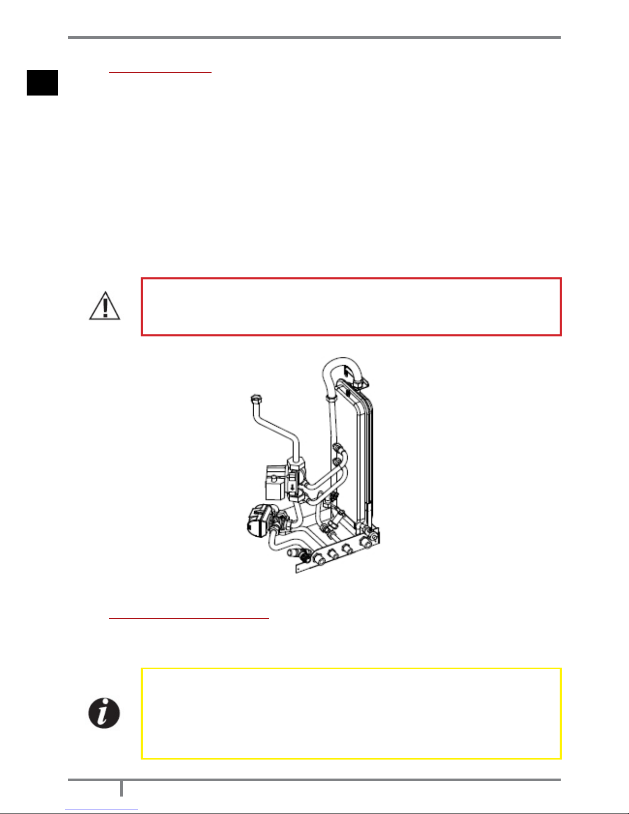
8.7 DOMESTIC HOT WATER PRODUCTION KIT (AQUOS 22 H2O / IBIS 22 H2O / IDRON 22 H2O
STOVES ONLY)
The AQUOS 22 H2O, IBIS 22 H2O and IDRON 22 H2O stoves are equipped with a complete kit for the production
of domestic water made up of:
• Plate heat exchanger
• A 3-way diverter valve
• Flow switch
• Pipes and ttings for connection
The kit comes preassembled by the manufacturer and it is designed to heat domestic water directly from the
home water supply system.
When hot water is required and the tap is turned, the internal water ow switch will send a signal to the diverter
valve to channel the hot water contained in the boiler to the plate heat exchanger. The temperature of
the domestic water highly depends on the temperature of the water inside the heating system. This can be
calculated to a good degree of accuracy by taking 10°-15°C away from the value shown on the stove control
panel (which is the temperature of the water in the boiler).
If hot domestic water is needed while the stove is ‘Switch-Off’ or in ‘ECOSTOP off’ mode, the stove will automatically
and immediately begin the start-up process to heat the water inside the boiler, and then the domestic hot water.
To ensure that the plate heat exchanger continues to work properly over time, one must be aware of the system
water hardness to prevent deposits from forming.
If the water in your home is very hard, you are advised to install a softening system upstream.
You are advised to service the plate exchanger annually to eliminate limescale and mineral
salts sediments or to replace the heating plates with new ones. These spare parts are
supplied by the manufacturer.
Fig. 24 - Domestic water production kit
8.8 WATER CHARACTERISTICS
The characteristics of the water used to ll the system are very important to prevent the build-up of mineral salts
and the formation of incrustations along the pipes, in the boiler and in the heat exchangers.
Therefore, please ASK YOUR PLUMBER FOR HIS ADVICE CONCERNING:
Hardness of water circulating in the system, to prevent problems of incrustation and
limescale, especially in the domestic water heat exchanger. (\x3e 25° French).
Installation of a water softener (if water hardness exceeds 25° French).
Filling the system with treated water (demineralised).
Possibly providing an anti-condensation circuit.
Installation of hydraulic shock absorbers to prevent water hammering along the ttings and
pipes.

27
AQUOS - IBIS - IDRON
EN
If you have very extensive systems (with a large amount of water) or which require frequent relling, the installation
of water softening systems.
It should be remembered that incrustations drastically reduce performance due to their
extremely low thermal conductivity.
9
ELECTRICAL CONNECTIONS
9.1 GENERAL PRECAUTIONS
Electrical safety of the system is ensured only when it is properly connected to an efcient earthing system made
in compliance with the safety standards in force: gas, water or heating systems pipes are not suitable as earth
connections.
One must check this essential safety requirement; if in doubt, request an accurate inspection of the electrical
system to be carried out by qualied personnel, because the boiler manufacturer is not responsible for any
damage caused by failure to earth the system.
Have professionally qualied personnel check the electrical system is suitable for the maximum power absorbed
by the heating system, ensuring in particular that the diameter of cables is appropriate for the power absorbed
by the loads.
The use of any component that is powered by electricity entails compliance with some basic rules such as:
• do not touch the appliance with wet and/or damp body parts and/or bare feet;
• do not pull the electric cables;
• do not leave the appliance exposed to weathering (rain, sun, etc.);
• do not allow the appliance to be used by children or inexperienced persons.
230V electrical power supply connection
Installation of the boiler accessory electrical components requires electrical connection to a 230 V – 50 Hz mains:
This connection must be state of the art according to the CEI standards in force.
Hazard!
Electrical installation must be carried out by a qualied technician only.
Before performing connections or any operation on the electrical parts, always disconnect
the power supply and make sure it cannot be accidentally reconnected.
Please note that the boiler electrical power line must be tted with a bipolar switch with
a contact gap greater than 3 mm, easy to access, in order to make any maintenance
operations quick and safe.
The power cable must be replaced by authorised technical personnel. Failure to comply with the provisions
listed above may compromise the safety of the appliance.
9.2 ELECTRICAL CONNECTION
First connect the power cable to the side of the boiler and then to a wall socket.
The main switch at the side must only be activated to switch the boiler on; otherwise, it is advisable to keep it
switched off.
It is recommended to disconnect the boiler power cable when the boiler is not used.
Fig. 25 - Electrical connection of the stove
28
AQUOS - IBIS - IDRON
EN
10
INITIAL START-UP
10.1 GENERAL PRECAUTIONS
Remove all components that could burn from the brazier and glass (manual, various adhesive labels and any
polystyrene).
Check that the brazier is positioned correctly and rests properly on the base.
Fig. 26 - Check the brazier
After a long period of inactivity, remove any pellets left in the hopper (using a vacuum
cleaner with a long pipe ), as they could have absorbed moisture, thereby altering their
original characteristics and no longer being suitable for combustion.
The rst start-up may not be successful as the feed screw is empty and does not always
manage to load the required amount of pellets in the brazier in time for the re to be
regularly ignited.
CANCEL THE FAILED START-UP ALARM STATUS BY PRESSING AND HOLDING KEY 1 (ESC).
REMOVE THE PELLETS FROM THE BRAZIER AND REPEAT START-UP.
If a ame does not ignite after a number of failed start-ups, even though the pellet supply is correct, make sure
the brazier is set in place correctly, which must be interlocked in its seat and free from any ash deposits. If no
anomaly is found during this inspection, there may be a problem with the product components or installation
may not be correct.
REMOVE THE PELLETS FROM THE BRAZIER AND CONTACT AN AUTHORISED TECHNICIAN.
Avoid touching the boiler during the initial start-up, as the paint in this stage hardens; by
touching the paint, the steel surface may be exposed.
It is good practice to guarantee effective ventilation in the room during the initial start-up,
as the boiler will emit some smoke and smell of paint.
Do not stand close to the product and air the room. The smoke and smell of paint will disappear after about an
hour of operation, however, remember they are not harmful in any case.
The boiler will be subject to expansion and contraction during the start-up and cooling phases, therefore slight
creaking noises may be heard.
This is absolutely normal as the structure is made of laminated steel and must not be considered a defect.
It is extremely important to make sure the boiler is not immediately overheated and the temperature is increased
gradually, initially using low power.
This will prevent damaging the ceramic or serpentine tiles, the welds and the steel structure.

29
AQUOS - IBIS - IDRON
EN
DO NOT EXPECT HEATING EFFICIENCY IMMEDIATELY!!!
10.2 OPENING/CLOSING THE DOOR
ATTENTION!
The door must be closed properly for the boiler to work correctly.
Use suitable protective clothing (such as gloves) to open the boiler door.
10.3 SETTINGS TO BE CARRIED OUT BEFORE THE INITIAL START-UP
Once the power cable is connected in the rear part of the stove, turn the switch, also placed at the rear, to
position (I). To switch the stove on or off press key 1 on the control panel.
Fig. 27 - Key and display
10.4 LOADING THE PELLETS
Fuel is loaded from the upper part of the stove by opening the door. Pour the pellets into the hopper.
To ease the procedure carry out the operation in two steps:
Pour half of the contents into the hopper and wait for the fuel to settle on the bottom.
Then complete the operation by pouring in the rest.
Never remove the protection grille from within the hopper. When loading prevent the pellet
bag from coming into contact with hot surfaces.
No other type of fuel other then pellets, in compliance with above-mentioned specications,
is to be inserted into the hopper.
Store the back-up fuel at a suitable safety distance.
Do not pour the pellets directly onto the brazier but only into the hopper.
Most of the stove surfaces are very hot (door, handle, glass, smoke outlet pipes, hopper
door, etc.). It is therefore recommended to avoid coming into contact with these parts
without adequate protective clothing.
11
MENU ITEMS
11.1 CONTROL PANEL DISPLAY
Menu items.

30
AQUOS - IBIS - IDRON
EN
Fig. 28 - Display
LEGEND
1 Boiler lighting/shutdown
2 Scrolling of programming menu to decrease.
3 Menu
4 Scrolling of programming menu to increase.
5 Decrease set temperature/programming functions.
6 Increase set temperature/programming functions.
7 Display.
11.2 MAIN MENU
It is accessed by pressing key 3 (menu). The items that are accessed are:
• Date and Time
• Timer
• Sleep (only with the stove on)
• Settings
• Info
Date and time setting
To set the date and time act as follows:
• Press the “menu” button.
• Select “Date and Time”.
• Select by pressing “menu”
• Scroll with the arrows and select the variables to be modied one at a time: Day, Hours, Minutes, Day number,
Month, Year.
• Select “menu” to conrm.
• Modify with the + - keys.
• Finally press “menu” to conrm and “esc” to exit.
Timer setting (see relative chapter)
Sleep setting (see relative chapter)
11.3 SETTINGS MENU
The SETTINGS menu allows to act on the boiler operating mode:
A. Language.
B. Cleaning (displayed only when the boiler is switched off).
C. Feed screw loading (displayed only when the boiler is switched off).
D. Tones.
E. External thermostat (activation).
F. Auto Eco (activation).
G. Eco-Shutdown T (default 10 minutes).
H. Pump on T (default 50°C).
I. Auxiliary boiler (default deactivated).
J. Pellet recipe.
K. Smoke rpm % ventilation.
L. Maximum power (1-5 - default 5).

31
AQUOS - IBIS - IDRON
EN
M. Components test (displayed only when the boiler is switched off)
N. “Chimney sweep” function (activated only when the boiler is switched on, for eld emissions test).
O. System conguration.
P. Season.
Q. Technical menu.
NOTE: Some of the items listed above cannot be activated in certain “system congurations”.
a - Language
To select the language act as follows:
• Press the “menu” button.
• Scroll to “Settings” using the arrows
• Press “menu” to conrm.
• Scroll to “language” using the arrows.
• Press “menu” to conrm.
• With the + - keys select the language of interest (IT/EN/DE/FR/ES/NL/PL/DA)
• Press “menu” to conrm and “esc” to exit.
b - Cleaning
To select “Cleaning” (only when the boiler is switched off) act as follows:
• Press the “menu” button.
• Scroll to “Settings” using the arrows
• Press “menu” to conrm.
• Scroll to “Cleaning” using the arrows.
• Press “menu” to conrm.
• Select “On” with the + - keys.
• Press “menu” to conrm and “esc” to exit.
c - Feed screw loading
To select “Feed screw loading” (only when the boiler is switched off) act as follows:
• Press the “menu” button.
• Scroll to “Settings” using the arrows
• Press “menu” to conrm.
• Scroll to “Feed screw loading” using the arrows.
• Press “menu” to conrm.
• Select “Enable” with the + - keys.
• Press “menu” to conrm and “esc” to exit.
d - Tones
This function is disabled by default, so to enable act as follows:
• Press the “menu” button.
• Scroll to “Settings” using the arrows
• Press “menu” to conrm.
• Scroll to “tones” using the arrows.
• Press “menu” to conrm.
• Select “On” with the + - keys.
• Press “menu” to conrm and “esc” to exit.
e - External thermostat (see relative chapter)
f - Auto-Eco activation
To select the Auto-Eco function act as follows:
• Press the “menu” button.
• Scroll to “Settings” using the arrows
• Press “menu” to conrm.
• Scroll to “Auto-Eco” using the arrows.
• Press “menu” to conrm.
• Select “On” with the + - keys.
• Press “menu” to conrm and “esc” to exit.
g - Eco Shutdown t
To select the Eco - shutdown t function act as follows:
• Press the “menu” button.
• Scroll to “Settings” using the arrows
• Press “menu” to conrm.
• Scroll to “Eco - shutdown t” using the arrows.

32
AQUOS - IBIS - IDRON
EN
• Press “menu” to conrm.
• Enter the minutes with the + - keys.
• Press “menu” to conrm and “esc” to exit.
h - Pump On T
To select the Pump On T function act as follows:
• Press the “menu” button.
• Scroll to “Settings” using the arrows
• Press “menu” to conrm.
• Scroll to “Pump On T” using the arrows.
• Press “menu” to conrm.
• Modify the °C with the + - keys.
• Press “menu” to conrm and “esc” to exit
i - Auxiliary boiler
One must install an additional module (optional) to enable start-up of an auxiliary boiler in the event the boiler
is switched off or in alarm conditions. By default this function is deactivated, if needed activate it to access the
settings menu.
l - Pellet Recipe
To change the recipe act as follows:
• Press the “menu” button.
• Scroll to “Settings” using the arrows
• Press “menu” to conrm.
• Scroll to “Pellet recipe” using the arrows.
• Press “menu” to conrm.
• Modify the % with the + - keys.
• Press “menu” to conrm and “esc” to exit
m - Smoke rpm % ventilation
To change the parameter act as follows:
• Press the “menu” button.
• Scroll to “Settings” using the arrows
• Press “menu” to conrm.
• Scroll to “Smoke rpm variation” using the arrows.
• Press “menu” to conrm.
• Modify the % with the + - keys.
• Press “menu” to conrm and “esc” to exit
n - Maximum power
To change the power act as follows:
• Press the “menu” button.
• Scroll to “Settings” using the arrows
• Press “menu” to conrm.
• Scroll to “Maximum power” using the arrows.
• Press “menu” to conrm.
• Change the power from 01 to 05 with the + - keys
• Press “menu” to conrm and “esc” to exit
o - Components test
To activate the “Components test” function (only when the boiler is switched off) act as follows:
• Press the “menu” button.
• Scroll to “Settings” using the arrows
• Press “menu” to conrm.
• Scroll to “Components test” using the arrows.
• Press “menu” to conrm.
• Select the test to be performed with the + - keys
• Press “menu” to conrm and “esc” to exit
p - Chimney sweep function
To activate the “Chimney sweep” function act as follows:
• Press the “menu” button.
• Scroll to “Settings” using the arrows
• Press “menu” to conrm.
• Scroll to the “Chimney sweep” function using the arrows.

33
AQUOS - IBIS - IDRON
EN
• Press “menu” to conrm.
• Select “On” with the + - keys (Off by default)
• Press “menu” to conrm and “esc” to exit
q - System conguration
To change the system conguration act as follows:
• Press the “menu” button.
• Scroll to “Settings” using the arrows
• Press “menu” to conrm.
• Scroll to “System conguration” using the arrows.
• Press “menu” to conrm.
• Change the conguration from 01 to 05 with the + - keys
• Press “menu” to conrm and “esc” to exit.
r - Season
To change the function act as follows:
• Press the “menu” button.
• Scroll to “Settings” using the arrows
• Press “menu” to conrm.
• Scroll to “Season” using the arrows.
• Press “menu” to conrm.
• Select “Summer” or “Winter” with the + - keys.
• Press “menu” to conrm and “esc” to exit.
s - Technical menu
To access the technical menu one must contact an assistance centre as one needs a password to enter.
To intervene on the “technical menu” act as follows:
• Press the “menu” button.
• Scroll to “Settings” using the arrows
• Press “menu” to conrm.
• Scroll to “Technical menu” using the arrows.
• Press “menu” to conrm.
• Select “Product Type”, “Service”, “Parameters”, “DHW Parameters”, “Meters memories”, “Enable fan” and
“Puffer data” with the + - keys.
• Press “menu” to conrm and “esc” to exit
11.4 ADJUSTMENTS MENU
To access the adjustments menu act as follows:
• Press the + - keys
• Scroll with the <> arrows and select “Set Room T” or “Set Water T” or “Exchanger Speed”
• Press “menu” to access the selected option.
• Modify with the + - keys.
• Press “menu” to conrm and “esc” to exit.
Important!
The stoves come in different types, some have a fan and some have domestic hot water
(DHW).
Therefore within the stove functions one must bear in mind the features of the purchased
product.

34
AQUOS - IBIS - IDRON
EN
12
PRELIMINARY NOTIONS
12.1 SYSTEM CONFIGURATIONS DEPENDING ON THE MODEL
Upon installation, the product must be set according to the type of system, selecting the appropriate parameter
in the “SETTINGS” menu.
The possible congurations are 5, as described below:
CONFIGURATION DESCRIPTION
1
Room temperature management via the boiler probe or by enabling the external room
thermostat.
2
2.1 Room temperature management via the boiler probe or by enabling the external room
thermostat; instantaneous DHW production with plate heat exchanger.
2.2 Room temperature management via the boiler probe or by enabling the external room
thermostat; instantaneous hot domestic water production for boiler or storage tank with
thermostat (optional).
3
Room temperature management via boiler probe or enabling the external room thermostat;
boiler hot domestic water production with ntc probe (10 kΩ ß3435).
4 External Puffer management controlled by thermostat.
5 External Puffer management controlled by ntc probe (10 kΩ ß3435).
Fig. 29 - Conguration 1 (factory setting for heating version only)

35
AQUOS - IBIS - IDRON
EN
Fig. 30 - Conguration 2.1 (factory setting for version with domestic hot water - DHW)
Fig. 31 - Conguration 2.2

36
AQUOS - IBIS - IDRON
EN
Fig. 32 - Conguration 3
Fig. 33 - Conguration 4

37
AQUOS - IBIS - IDRON
EN
Fig. 34 - Conguration 5
LEGEND
1 Stove
2 Heating delivery
3 Heating return
4 Zone valves
5 Heating bodies
6 Hot domestic water
7 Cold domestic water
8 Domestic water boiler
9 Diverter valve
10 Boiler thermostat
11 Thermostatic mixing valve
12 Domestic water 10 kΩ β3434 NTC probe
13 Heating puffer
14 Heating system circulator
15 Puffer thermostat
16 Puffer 10 kΩ β3434 NTC probe
17 Safety valve
13
OPERATION
13.1 OPERATING MODE
The operating mode for hydro boilers is AUTOMATIC only (manual mode is not envisioned). Flame modulation is
managed according to the “System conguration” of the room probe placed on the rear of the appliance (see
drawing), by the external thermostat, by the boiler water temperature or by the NTC probes.

38
AQUOS - IBIS - IDRON
EN
Fig. 35 - Operating mode
13.2 EXTERNAL THERMOSTAT CONNECTION (E)
EXTERNAL THERMOSTAT (not included with the boiler, to be provided by the user).
The temperature of the boiler can also be controlled by an external room thermostat. It is located in a central
position of the room where the boiler is installed. It provides a closer match between the heating temperature
requested of the boiler and what it actually provides.
Fig. 36 - Electrical thermostat connection
LEGEND
POS. 1-2 External thermostat
POS. 3-4 Puffer/boiler probe
POS. 5 Earthing
POS. 6-7 Additional boiler

39
AQUOS - IBIS - IDRON
EN
Connect the cables from the external thermostat to points 1-2 of the terminal block on the boiler.
Once the thermostat has been connected one must enable it.
In order to do this, proceed as follows:
• Press the “menu” button.
• Scroll to “Settings” using the arrows.
• Select by pressing “menu”.
• Scroll once again to “External thermostat” using the arrows.
• Select by pressing “menu”.
• Press the - + buttons.
• Select “On” to activate the external thermostat.
• Press the “menu” button to conrm.
• Press the “esc” button to exit.
13.3 START-UP
Press key 1 (esc) to begin start-up, the control panel displays ON with a ashing ame. When the ame stops
ashing the boiler has reached the “power output” operating mode.
The room temperature set by default is 20°C, if one wishes to change it act as instructed in the adjustments
menu; act likewise to set the heating water temperature and the room fan speed (if envisaged). To activate
external thermostat if any see the relative section.
13.4 POWER OUTPUT
Once the start-up stage is complete the control panel will display ON with a xed ame at level 3. The subsequent
ame modulation at lower or higher powers is managed autonomously and upon reaching the temperatures
set in the “System conguration”.
13.5 PROGRAMMED MODE (TIMER) - MAIN MENU
Setting the current day and time is essential for the proper operation of the timer.
There are six TIMER programmes, for each one the user can decide the start-up and shutdown time as well as the
day of the week in which it is active.
When one or more programmes are active, the panel alternately displays the boiler status and TIMER “n” whereby
“n” is the number relating to the activated timer programmes, separated from each other with a dash
Example:
TIMER 1 Timer programme 1 active.
TIMER 1-4 Timer programmes 1 and 4 active.
TIMER 1-2-3-4-5-6 Timer programmes all active.
EXAMPLE OF PROGRAMMING
With boiler on or off:
access the MENU,
scroll to TIMER with the <> arrows,
press the “Menu” key
the system proposes “P1” (Press the <> keys for the subsequent timers P2,P3, P4, P5, P6)
to activate “P1” press the “Menu” key
press + - and select “ON”
conrm with the “Menu” key
At this point it will propose 00:00 as starting time, with key + - adjust the starting time and press the “menu” key
to conrm.
The next step proposes a shutdown time of 10 minutes above that set for start-up: press the + key and adjust the
shutdown time, conrm with the “menu” key.
Subsequently the system proposes the days of the week in which to activate or deactivate the previously set
timer. With the - or + key highlight with the white background the day in which one wishes to activate the timer
and conrm with the “menu” key. If no day of the week is conrmed as active, in turn the timer programme will
not appear active in the status screen.
Continue to program the following days or press “ESC” to exit. Repeat the procedure to program the other
timers.

40
AQUOS - IBIS - IDRON
EN
13.6 PROGRAMMING EXAMPLES:
P1 P2
on off day on off day
08:00 12:00 mon 11:00 14:00 mon
Boiler on from 08:00 to 14:00
on off day on off day
08:00 11:00 mon 11:00 14:00 mon
Boiler on from 08:00 to 14:00
on off day on off day
17:00 24:00 mon 00:00 06:00 tue
Boiler on from 17:00 on monday to 06:00 on tuesday
13.7 NOTES FOR TIMER OPERATION
• Start-up with the timer always takes place with the last temperature and ventilation settings (or with default
20°C and V3 settings in the event they have never been changed).
• Start-up time ranges from 00:00 a 23:50
• If the shutdown time is not already memorised, it proposes a start-up time in + 10 minutes.
• A timer programme switches the boiler off at 24:00 of one day and another programme switches it on at 00:00
of the next day: the boiler stays on.
• A programme proposes a start-up and shutdown in times included within another timer programme: if the
boiler is already on, start will not have any effect, while OFF will switch it off.
• In the boiler on and timer active condition, press the OFF key and the boiler will switch off, it will switch on
automatically at the next time set on the timer.
• In the boiler off and timer active condition, press the ON key and the boiler will switch on, it will switch off at
the time set on the active timer.
13.8 AUTO ECO MODE (SEE SECTION F-G SETTINGS MENU PAGE 30)
To activate the “Auto Eco” mode and adjust the time refer SETTINGS MENU page 30.
The possibility to adjust the “ECO shutdown t” comes from the need to ensure proper operation in the various
rooms the boiler can be installed in and prevent continuous shutdowns and start-ups in the event the temperature
is subject to sudden changes (air currents, poorly insulated rooms, etc.).
The ECO shutdown procedure is activated automatically when all the power demand devices involved in the
“system conguration” are satised: room probe/external thermostat, ow switch, puffer thermostat/ntc (10 kΩ
ß3435) or boiler thermostat/ntc (10 kΩ ß3435). If all devices present are satised the “ECO shutdown t” time
decrease starts (by default 10 minutes, it can be changed within the “Settings menu”). During this stage the
panel displays ON with a small ame and alternately Chrono (of active) - Eco active. The minutes indicating the
countdown for the Eco Stop are shown at the top of the display. The ame goes into P1 and stays there until the
programmed “Eco shutdown t” time has elapsed and if the conditions are still satised, it goes into the shutdown
stage. The ECO switch off countdown resets if one of the devices boosts power again.
When switch off starts the panel displays: Off - Eco Active - small ashing ame.
Once the boiler has reached the off condition, the panel displays OFF-ECO with the extinguished ame symbol.
To restart from ECO the following conditions must be satised simultaneously:
• Power demand
• After 5 minutes from the beginning of shutdown.
• TH2O < TSetH2O.
• If the domestic hot water (DHW) demands power - if envisaged - the rst 5’ are ignored and the boiler restarts
as needed.
NOTE: In conguration 4 - 5 the Auto Eco mode is enabled automatically. Even when one sets the “summer”
function in conguration 2 - 3 it is enabled automatically. In the cases where it is designed to be active, it is not
possible to deactivate the mode.
13.9 SLEEP FUNCTION (MAIN MENU)
The sleep function is activated only when the boiler is switched on and allows to quickly set a time at which the
product must switch off.
To set the Sleep function act as follows:

41
AQUOS - IBIS - IDRON
EN
• Enter MENU
• Scroll to SLEEP with the <> arrows
• Press Menu
• With the + - keys adjust the desired shutdown time.
The panel proposes a shutdown time of 10 minutes from the current time, adjustable with key 4 until the next day
(I can therefore delay the shutdown for up to a maximum of 23 hours and 50 minutes).
If the SLEEP function is active with the TIMER active the rst has priority over the latter, therefore the boiler will not
switch off at the time set on the timer but instead by the time established by the sleep function, even if later than
the time set on the timer.
13.10 AUXILIARY BOILER (SEE SECTION I SETTINGS MENU PAGE 30)
One must install an additional module (optional) to enable start-up of an auxiliary boiler in the event the stove
is switched off or in alarm conditions. By default this function is deactivated, if needed activate it to access the
settings menu.
13.11 PELLETS RECIPE (SEE SECTION J SETTINGS MENU PAGE 30)
This function is for adapting the stove to the pellets that are being used. In fact, as there are several types of
pellets on the market, boiler operation is extremely variable depending on the fuel quality. In the event the
pellets tend to clog the brazier due to an excessive load of fuel or in the event the ame is always high even at
low powers and, vice versa if the ame is low one can decrease/increase the amount of pellets in the brazier:
The available values are:
-3 = Decrease by 30% compared to factory settings.
-2 = Decrease by 20% compared to factory settings.
-1 = Decrease by 10% compared to factory settings.
0 = No variation.
1 = Increase by 5% compared to factory settings.
2 = Increase by 10% compared to factory settings.
3 = Increase by 15% compared to factory settings.
13.12 SMOKE RPM VARIATION (SEE SECTION K SETTINGS MENU PAGE 30)
If the installation presents difculties for smoke evacuation (no draught or no pressure in the duct), the smoke
and ash expulsion speed can be increased. This change resolves all the potential problems related to pellets
clogging in the brazier and deposits forming at the bottom of the brazier itself caused by poor quality fuel or fuel
that produces a lot of ashes. The values available are from -30% to +50% with variations of 10 percentage points
at a time. The variation in negative can be used in case the ame is too low.
13.13 PUMP ON T (EXPERIENCED USERS ONLY) - SEE SECTION H SETTINGS MENU PAGE 30
This menu item allows to adjust the pump activation temperature.
13.14 MAXIMUM POWER (EXPERIENCED USERS ONLY) - SEE SECTION L SETTINGS MENU PAGE
30
It allows to set the maximum ame limit at which the boiler can operate to reach the set temperature target.
13.15 CHIMNEY SWEEP FUNCTION (FOR MAINTENANCE TECHNICIANS ONLY) - SEE SECTION N
SETTINGS MENU PAGE 30
This function can be activated only when the boiler is on and with power output and heating operation power
with parameters P5, with fan (if present) in V5. Any loading/smoke ventilation percentage corrections must be
taken into account. This status lasts 20 minutes, the countdown is displayed on the panel. During this interval the
thermostat/puffer/room set point/H20 set point are not taken into account, only the safety shutdown at 85°C
remains active. At any time the technician can interrupt this stage by quickly pressing the on/off key.
13.16 SEASON FUNCTION (SEE SECTION P SETTINGS MENU PAGE 30)
In congurations 2 and 3, by enabling the “summer” function, the deviation of the 3-way valve to the heating
system is inhibited in order to prevent the radiators from heating up, therefore the ow is always directed towards
the domestic hot water (DHW) - if envisaged.
By activating the “summer” option one automatically enables the auto-eco function (it cannot be deactivated).
The room probe/external thermostat are not taken into account.

42
AQUOS - IBIS - IDRON
EN
13.17 FEED SCREW (SEE SECTION D SETTINGS MENU PAGE 30)
Allows to ll the pellets loading system. It can only be activated with the boiler switched off, it displays an 180”
countdown after which the feed screw stops automatically, as when exiting the menu.
13.18 COMPONENTS TEST (SEE SECTION M SETTINGS MENU PAGE 30)
It can only be carried out with the boiler switched off, it allows to select the components to be tested:
• Spark plug: it is turned on for a xed time of 1 minute during which the panel displays the countdown seconds.
• Feed screw: it is powered for a xed time of 1 minute during which the panel displays the countdown seconds.
• Extractor: it is activated at 2500 rpm for a xed time of 1 minute during which the panel displays the countdown seconds.
• Exchanger: it allows to carry out the test in V5 for a xed time of 1 minute during which the panel displays the
countdown seconds.
• Pump: it is activated for a xed time of 10 seconds during which the panel displays the countdown.
• 3 way: the 3 way valve is activated for a xed time of 1 minute during which the panel displays the countdown seconds.
14
SAFETY DEVICES AND ALARMS
14.1 SAFETY DEVICES
The product is supplied with the following safety devices
14.2 PRESSURE SWITCH
Monitors pressure in the smoke duct. It is designed to shut down the pellets feed screw in the event of an
obstructed ue or signicant back-pressure. (wind)
14.3 SMOKE TEMPERATURE PROBE
Detects the temperature of the smoke, thereby enabling start-up or stopping the product when the temperature
drops below the preset value.
14.4 CONTACT THERMOSTAT IN THE FUEL HOPPER
If the temperature exceeds the preset safety level, it immediately shuts down boiler operation.
14.5 CONTACT THERMOSTAT IN THE BOILER
If the temperature exceeds the preset safety level, it immediately shuts down boiler operation.
14.6 WATER TEMPERATURE PROBE
If the water temperature approaches the shutdown temperature (85°C) the probe makes the boiler perform the
“OFF Stand-by” automatic shutdown.
14.7 ELECTRICAL SAFETY
The product is protected against sudden current surges by a main fuse in the power supply panel on the rear
part of the product. Other fuses that protect the electronic boards are found on the latter.
14.8 SMOKE FAN
If the fan stops, the electronic board promptly shuts off the pellets supply and an alarm message is displayed.
14.9 GEAR MOTOR
If the gear motor stops, the boiler will continue to run until the ame goes out due to lack of fuel and until a
minimum level of cooling is reached.
14.10 TEMPORARY POWER CUT
If the power cut lasts less than 10” the boiler returns to its previous operating status; if it lasts more it carries out a
cooling/restart cycle.
14.11 FAILED START-UP
If during ignition no ame develops, the boiler will go into alarm condition.

43
AQUOS - IBIS - IDRON
EN
14.12 ANTIFREEZE FUNCTION
If the probe in the boiler detects a water temperature of less than 5°C, the circulation pump is automatically
activated to prevent the system from freezing.
14.13 PUMP ANTI-SEIZURE FUNCTION
If the pump is not used for prolonged periods, it is activated periodically for a few seconds to prevent it from
seizing up.
TAMPERING WITH THE SAFETY DEVICES IS PROHIBITED
If the product is NOT used as described in this instruction manual, the manufacturer declines
all liability for any damage caused to persons and property. The manufacturer furthermore
refuses to accept responsibility for damage to persons and property arising from the failure
to observe all the rules contained in the manual and in particular:
• All the necessary measures and/or precautions must be adopted when performing
maintenance, cleaning and repairs.
• Do not tamper with the safety devices.
• Do not remove the safety devices.
• Connect the product to an efcient smoke expulsion system.
• Verify that the room in which the appliance will be installed is adequately ventilated.
The product can be started-up and the automatic function of the probe restored only after
having eliminated the cause that triggered the safety system. This manual will help you
understand which anomaly has occurred, and explain how to intervene according to the
alarm message displayed on the appliance.
14.14 ALARM ALERTS
Whenever an operating condition other than that designed for the regular operation of the boiler occurs, there
is an alarm condition.
The control panel gives information on the reason of the alarm in progress. A sound signal is not envisioned for
alarms A01-A02 only so to PANEL ALERTnot disturb the user in the event of pellets running out in the hopper during
the night.
PANEL ALERT TYPE OF PROBLEM SOLUTION
A01 The re does not ignite.
Check whether the brazier is clean / level of pellets
in the hopper.
A02 The re goes off abnormally. Check the level of pellets in the hopper.
A03 Thermostat
alarms
The temperature of the pellets hopper or the
water temperature exceed the envisioned
safety threshold.
Wait for the cooling stage to end, cancel the alarm
and restart the boiler setting the fuel loading at
minimum (SETTINGS menu - Pellets recipe). If the
alarm persists, contact the service centre. Check if
the room fan works properly (if present).
A04 Smoke overheating.
The set smoke threshold has been exceeded. Reduce
pellets loading (SETTINGS menu - Pellets recipe).
A05 Pressure
switches alarm
Smoke pressure switch intervention or water
pressure insufcient.
Verify chimney obstruction / door opening or
hydraulic system pressure.
A08 Abnormal smoke fan operation. If the alarm persists, contact the service centre.
A09 Smoke probe faulty. If the alarm persists, contact the service centre.
A19 Water probe faulty.
Water probe disconnected / interrupted / defective
/ not recognised.
A20 Puffer probe alarm.
Puffer probe disconnected / interrupted / defective
/ not recognised.
SERVICE
Routine maintenance alert (it does not block
the system).
When this ashing message appears upon start-up, it
means that the preset operating hours have elapsed
before maintenance. Contact the service centre.

44
AQUOS - IBIS - IDRON
EN
14.15 ALARM RESET
To reset the alarm one must press and hold key 1 (ESC) for a few seconds. The boiler performs a check to
determine if the cause of the alarm persists or not.
In the rst case the alarm will still be displayed, in the second case it will go onto OFF.
If the alarm persists, contact the service centre.
14.16 NORMAL SHUTDOWN (ON THE PANEL: OFF WITH FLASHING FLAME)
If the shutdown key is pressed or if there is an alarm signal, the boiler goes into the thermal shutdown phase which
entails the automatic execution of the following stages:
• It stops pellets loading
• The room fan (if provided) maintains the set speed until the smoke T reaches 100°C, then it automatically sets
itself at the minimum speed until it reaches the shutdown temperature
• The smoke fan sets itself at maximum speed and maintains it for a xed time of 10 minutes, at the end of which
if the smoke T has fallen below the shutdown threshold it switches off permanently, otherwise it sets itself at the
minimum speed until it reaches such threshold before switching off.
• If the boiler was shutdown regularly but, due to thermal inertia the smoke temperature exceeds the threshold
again, the shutdown stage restarts at the minimum speed until the temperature goes down.
14.17 BLACKOUT WITH THE BOILER ON
In the event of a power cut (BLACKOUT) the boiler behaves as follows:
• Blackout below 10”: it returns to its operation in progress;
• In the event of a power cut that lasts over 10” with the boiler on or in the start-up stage, when the boiler is
powered again it goes back to the previous operating condition with the following procedure:
1) It cools down activating the smoke extractor at minimum power for 10’ and goes onto the next point;
1) It takes the boiler back to the operating condition before the blackout.
During stage 1 the panel displays ON BLACK OUT.
During stage 2 the panel displays Start-up.
If during stage 1 the boiler receives commands from the panel and thus carried out manually by the user, then
the boiler stops executing the blackout recovery status and proceeds to restart or shutdown as requested by
the command.
14.18 BLACKOUT ABOVE 10” WITH BOILER IN SHUTDOWN STAGE
In the event there is a power cut that lasts MORE THAN 10” with the boiler in the shutdown stage, when the
boiler is powered again it restarts in shutdown mode even if the smoke temperature has fallen under 45°C in the
meanwhile. This last stage can be skipped by pressing key 1 (esc) (it goes into start-up) and by pressing it again
(it recognises that the boiler is switched off).
15
MAINTENANCE AND CLEANING
Fig. 37 - Example of a clean brazier Fig. 38 - Example of a dirty brazier
ATTENTION!
All the cleaning operations of all parts must be performed with a completely cold product
and the plug disconnected.
The product requires little maintenance if used with certied high quality pellets.

45
AQUOS - IBIS - IDRON
EN
15.1 DAILY OR WEEKLY CLEANING PERFORMED BY THE USER
15.2 BEFORE EACH START-UP
Clean the ash and any deposits in the brazier that could clog the air passage holes.
If the pellets in the hopper nish, unburned pellets may accumulate in the brazier. Always empty the residue in
the brazier before startingup.
REMEMBER THAT ONLY A CORRECTLY POSITIONED AND CLEAN BRAZIER CAN GUARANTEE
START-UP AND OPTIMAL OPERATION OF YOUR PELLET PRODUCT.
For the brazier to be cleaned properly, remove it from its housing completely and thoroughly clean all the holes
and the grate on the bottom.
If good quality pellets are used, you will normally only need to use a brush to restore the optimal operating
conditions of the component.
15.3 CLEANING THE GLASS
It is recommended to clean the ceramic glass with a dry brush, or if it is very dirty, spray a little specic detergent
and clean with a cloth.
ATTENTION!
Do not use abrasive products and do not spray the glass spray cleaner on the painted parts
or the door gaskets (ceramic bre cord).
15.4 CLEAN THE EXCHANGER AND THE UNDERGRATE SPACE EVERY 2/3 DAYS.
Cleaning the exchanger and the undergrate space is a simple operation but very important for always
maintaining performance as declared.
Therefore we recommend cleaning the internal exchanger every 2-3 days, performing these simple operations
in sequence:
• Activate the “CLEANING” function – when the stove is switched of press - menu “3”, select“Settings”, with
the <> arrows “2-4” select “Cleaning”, conrm with “Menu” “3”, activate cleaning “ON” by pressing the +-
keys “5-6”. This procedure activates the smoke extraction fan on maximum power to expel the soot that is
dislodged when the exchanger is cleaned.
• Clean the pipe unit – Using the hook provided, shake the rods located under the top (A to Fig. 39 page
46 and Fig. 40 page 46) vigorously 5-6 times. This operation removes the soot that has deposited on the
exchanger smoke ducts during normal stove operation.
• Clean the smoke conveyor compartment see Fig. 39 page 46 for AQUOS 15-22-22 H2O / IBIS 15-22-22 H2O
/ IDRON 15-22-22 H2O models - Stoves are tted with a removable ash pan “C” designed to collect any soot
and ash build-up.
• Clean the smoke conveyor compartment see Fig. 40 page 46 for IBIS 11 / IDRON 11 models - Open the
door, insert the hook onto the rod of the scraper B, shake it vigorously 5-6 times along the entire length.
Remove the hook and reposition the rod B fully in its seat. This will help the fan expel any soot build-up which
may have fallen during the previous pipe unit cleaning process. (After shaking the rods A, always shake the
scraper B too).
• Disable the “CLEANING” function - this function is automatically disabled after two minutes. If one needs to
stop this function in advance press the “Esc” key.
If these cleaning operations are not performed every 2-3 days, the stove could go into
alarm conditions due to ash clogging after several hours of operation.

46
AQUOS - IBIS - IDRON
EN
Fig. 39 - Cleaning the internal pipe unit using scrapers (Aquos
15-22-22 H2O / Ibis 15-22-22 H2O / Idron 15-22-22 H2O)
Fig. 40 - Cleaning the lower drawer (Ibis 11 / Idron 11)
15.5 PERIODIC CLEANING PERFORMED BY A QUALIFIED TECHNICIAN
15.6 CLEANING THE HEAT EXCHANGER
Half-way through the winter season, but especially at the end of it, the compartment through which the exhaust
smoke passes will need to be cleaned. This cleaning process is mandatory in order to facilitate the general
removal of all combustion residue, before it becomes very difcult to remove it due to the humidity compacting
it over time.
ATTENTION: For your safety, the frequency with which the exhaust smoke system is cleaned
depends on the intensity of use of the stove.
15.7 CLEANING THE EXCHANGER AND PIPE UNIT (AQUOS 15-22-22 H2O / IBIS 15-22-22 H2O
/ IDRON 15-22-22 H2O)
15.8 CLEANING THE UPPER COMPARTMENT
When the stove is cold, remove the top, remove the ceramics/sides, by loosening the relative fastening screws
before removing the drivers “B” and then remove the boiler cover “C” At this point, remove the four turbulators
“D” and using a rigid rod or a bottle brush, clean the internal pipe unit and the turbulators, removing all of the
accumulated ash.
Check the cover gasket and replace it if necessary.
ATTENTION: It is advisable to carry out the cleaning of the upper exchanger at the end of
the season and possibly by an authorised technician in order to replace the gasket that is
below plug “C”. (Fig. 41 page 47).

47
AQUOS - IBIS - IDRON
EN
15.9 CLEANING THE LOWER COMPARTMENT
Remove the ash drawer “G”, empty it and using the nozzle of a vacuum cleaner remove any ash and soot that
may have built up under the drawer “G”. Remove the brazier “F” and clean it every 2/3 days.
Remove the drawer “E”, empty it and using the nozzle of a vacuum cleaner remove any ash that may have built
up in the housing of the drawer “E”.
ATTENTION: It is advisable to clean the lower compartment “E” once a week and in any
case according to the fuel consumption.
Fig. 41 - Cleaning the pipe unit, turbulators and lower compartment (Aquos 15-22-22 H2O / Ibis 15-22-22 H2O / Idron 15-22-22 H2O)
15.10 CLEANING THE EXCHANGER AND PIPE UNIT (IBIS 11 / IDRON 11)
15.11 CLEANING THE UPPER COMPARTMENT
When the stove is cold, remove the top, remove the ceramics/sides, by loosening the relative fastening screws
before removing the drivers “B” and then remove the boiler cover “C” At this point, remove the four turbulators
“D” and using a rigid rod or a bottle brush, clean the internal pipe unit and the turbulators, removing all of the
accumulated ash.
Check the cover gasket and replace it if necessary.
ATTENTION: It is advisable to carry out the cleaning of the upper exchanger at the end of
the season and possibly by an authorised technician in order to replace the gasket that is
below plug “C”. (Fig. 42 page 48).
15.12 CLEANING THE LOWER COMPARTMENT
Remove the ash drawer “G”, empty it and using the nozzle of a vacuum cleaner remove any ash and soot that
may have built up under the drawer “G”. Remove the brazier “F” and clean it every 2/3 days.
Loosen the screws and remove the plug “E” and using the nozzle of a vacuum cleaner, remove any ash and soot
that may have built up in the exchanger “H”.

48
AQUOS - IBIS - IDRON
EN
ATTENTION: It is advisable to clean the lower compartment “E” once a week and in any
case according to the fuel consumption.
Check the seal of the ceramic bre gasket on the plug and replace it if necessary. Check the seal of the door
gasket and replace it if necessary.
At the end of the season one must clean the compartment under the brazier and the inside of the heat exchanger.
This general cleaning should be carried out at the end of the season in order to facilitate the general removal of
all combustion residues, without waiting too long, because with time and humidity these residues can become
compacted.
Fig. 42 - Cleaning the pipe unit, turbulators and lower compartment (Ibis 11 / Idron 11)
15.13 CLEANING THE SMOKE DUCT AND GENERAL CHECKS:
Clean the smoke exhaust, especially around the T-ttings, curves and any horizontal sections. For information on
cleaning the ue, contact a chimney sweeper.
Check the seal of the ceramic bre gaskets on the door of the stove. If necessary, order new replacement
gaskets from the retailer or contact an authorized service centre to carry out this task.
Fig. 43 - T-tting

49
AQUOS - IBIS - IDRON
EN
ATTENTION:
The frequency with which the smoke exhaust must be cleaned depends on the use of the
stove and the type of installation.
We recommend contacting an authorised service centre for end-of-season maintenance
and cleaning as the abovementioned operations will be performed together with a general
inspection of the components.
15.14 END-OF-SEASON SHUTDOWN
At the end of each season, before switching the product off, it is recommended to remove all the pellets from
the hopper with a vacuum cleaner that has a long pipe.
The appliance must be disconnected from the mains when it is not used. It is recommended to remove the
power cable for additional safety, especially in the presence of children.
The service fuse may have to be replaced if the control panel display does not go on when the product is next
switched on by pressing the main switch on its side.
There is a fuse compartment on the side of the product, under the power socket. After having disconnected the
plug from the socket, use a screwdriver to open the cover of the fuse compartment and if necessary, replace
them (3.15 A delayed).
Fig. 44 - Fuse compartment

50
AQUOS - IBIS - IDRON
EN
16
PROBLEMS/CAUSES/SOLUTIONS
16.1 CHECKING THE INTERNAL COMPONENTS
ATTENTION!
The internal electromechanical components must only be checked by qualied personnel
whose technical expertise includes combustion and electricity.
It is recommended to perform this routine maintenance annually (with a scheduled service contract), which
focuses on a visual and functional verication of the internal components. The following is a summary of the
necessary checks and/or maintenance for the product to work correctly.
PARTS/INTERVAL EVERY DAY EVERY WEEK 15 DAYS 60-90 DAYS
EVERY
SEASON
Clean the brazier * X
Clean the ash collection
compartment with a vacuum
cleaner *
X
Clean the ash pan X
Clean the glass X
Clean the turbulators X
Clean the lower ash pan X
Clean the “T” exhaust ttings
(outside the stove)
X
Clean the exchangers and remove
ash and incrustations
X
Clean the smoke tting X
Circulation pump inspection X
Hydraulic leaks inspection X
Door gasket inspection X
Start-up spark plug inspection X
* WITH POOR QUALITY PELLETS CLEANING FREQUENCY MUST BE INCREASED.
ATTENTION:
All repairs must only be carried out by a specialised technician, with the product switched
off and the plug disconnected.
If the product is NOT used as described in this instruction manual, the manufacturer declines
all liability for any damage caused to persons and property.
ANOMALY POSSIBLE CAUSES SOLUTIONS
Pellets are not being fed into the
combustion chamber.
The pellet hopper is empty Fill the hopper with pellets.
Sawdust has blocked the feed screw
Empty the hopper and remove the
sawdust from the feed screw by hand.
Faulty gear motor Replace the gear motor.
Faulty electronic board Replace the circuit board.

51
AQUOS - IBIS - IDRON
EN
ANOMALY POSSIBLE CAUSES SOLUTIONS
The re goes out or the appliance
stops automatically.
The pellet hopper is empty Fill the hopper with pellets.
The pellets are not fed See the previous anomaly.
The pellet temperature safety probe
has been triggered
Let the product cool down, restore the
thermostat until the problem is resolved
and switch the product back on. If the
problem persists contact Technical
Assistance.
The door is not closed properly or the
gaskets are worn
Close the door and replace the gaskets
with original ones.
Unsuitable pellets
Change the type of pellets with those
recommended by the manufacturer.
Low pellet supply
Have the fuel ow checked following
the booklet instructions.
The combustion chamber is dirty
Clean the combustion chamber,
following the booklet instructions.
Clogged outlet Clean the smoke duct.
Faulty smoke extraction motor
Check the motor and replace it, if
necessary.
Pressure switch faulty or defective Replace the pressure switch.
The product works for a few minutes
and then switches off.
Start-up phase is not completed Repeat start-up.
Temporary power cut Wait for the automatic restart.
Clogged smoke duct Clean the smoke duct.
Faulty or malfunctioning temperature
probes
Check and replace the probes.
Faulty spark plug
Check the spark plug and replace it, if
necessary.
Pellets accumulate in the brazier, the
glass of the door gets dirty and the
ame is weak.
Insufcient combustion air.
Clean the brazier and check that all
the holes are clear. Perform a general
cleaning of the combustion chamber
and the smoke duct. Check that the air
inlet is not obstructed.
Damp or unsuitable pellets. Change the type of pellets.
Faulty smoke evacuation motor.
Check the motor and replace it, if
necessary.
The smoke evacuation motor does not
work.
No electrical supply to the stove.
Check the mains voltage and the
protection fuse.
The motor is faulty.
Check the motor and capacitor and
replace them, if necessary.
Defective motherboard. Replace the electronic board.
Control panel broken. Replace the control panel.
The convection air fan never stops. (IF
PROVIDED)
Faulty or malfunctioning temperature
control probe.
Check the probe and replace it, if
necessary.
Faulty fan.
Check the operation of the motor and
replace if necessary.
Silencer card of fan defective. Replace silencer card.

52
AQUOS - IBIS - IDRON
EN
ANOMALY POSSIBLE CAUSES SOLUTIONS
In the automatic position the stove
always runs at full power.
Thermostat is set to minimum. Set the thermostat temperature again.
The room thermostat is in the maximum
position.
Set the thermostat temperature again.
Faulty temperature probe.
Check the probe and replace it, if
necessary.
Faulty or malfunctioning control panel.
Check the panel and replace it, if
necessary.
The product does not start.
No power supply.
Check that the plug is inserted and the
main switch is in the “I” position.
Pellet temperature probe triggered. Check recipe parameters.
Blown fuse. Replace the fuse.
Pressure switch broken (lockout
indicated).
Water pressure low in stove.
Water temperature probe triggered. Contact the service centre.
Clogged smoke exhaust or smoke duct.
Clean the smoke exhaust and/or the
smoke duct.
No increase in temperature with stove
in operation.
Incorrect combustion adjustment. Check recipe.
Boiler/system dirty. Check and clean the boiler.
Insufcient stove power.
Check that the stove is properly sized
for the requirements of the system.
Poor pellets quality. Use of manufacturer pellets.
Condensation in boiler.
Incorrect temperature setting. Set the stove to a higher temperature.
Insufcient fuel consumption. Check recipe.
Radiators cold in winter.
Room thermostat (local or remote) set
too low. If remote thermostat, check if
it is defective.
Set it at a higher temperature or
replace it (if remote).
Circulator does not run because
blocked.
Free up the circulator by removing
the plug and turning the shaft with a
screwdriver.
Circulator does not run.
Check the electrical connections of
the circulator; replace if necessary.
Radiators have air in them. Bleed the radiators.
High temperature variability of
domestic water.
Water ow rate too low.
Increase the water ow rate (minimum
3 litres per minute).
Little domestic hot water is provided.
Insufcient mains water pressure.
Check the calibration of the pressure
reducer valve.
Tap or mixer clogged with limescale. Install an autoclave.
Water unit clogged. Check and clean.
Clean or replace the plate heat
exchanger.
Hot water is not provided. Circulator (pump) blocked. Free the circulator (pump).

NOTE

NOTE

NOTE

CADEL srl
FREEPOINT by Cadel
Via Foresto Sud, 7
31025 Santa Lucia di Piave (TV) - ITALY
tel. +39.0438.738669
fax +39.0438.73343
www.cadelsrl.com
Partner of:
pellet stoves· wood stoves· wood cooking stoves
thermostoves· pellet fireplace inserts
Rev.02 - 2014
 Loading...