

Page 1

Installation and operating instructions
for the MAX CADDY WOOD FURNACE
(PF01102 model)
Certified according to CSA B415.1-10, CSA B366.1, UL391,
CSA C22.2 NO.236, UL 1995, CAN/CSA B140.4 and UL 727
FURNACE MODELS INCLUDED IN THIS MANUAL
COMBINATION
WOOD ONLY
20 kW / 25 kW AND OIL
Read these instructions carefully before installing
and operating your furnace.
CONGRATULATIONS!
You have purchased one of the finest wood or combination furnaces available
on the market. We are confident that your furnace will provide years of comfort
and safe operation.
Please keep this document!
This manual is available for free download on the manufacturer’s
Verified and tested for Canada and
the United States by an accredited
laboratory.
Eco-energy at the hearth
of your home
45833A
Printed in Canada 07-06-2016
web site. It is a copyrighted document. Re-sale is strictly
prohibited. The manufacturer may update this manual from time
to time and cannot be responsible for problems, injuries, or
damages arising out of the use of information contained in any
manual obtained from unauthorized sources.
PSG
250, de Copenhague,
St-Augustin-de-Desmaures (Quebec)
CANADA G3A 2H3
Page 2

TABLE OF CONTENT
1. INTRODUCTION ......................................................................................................................................................................... 5
2. APPLIANCE PERFORMANCE
3. GENERAL FEATURES .............................................................................................................................................................. 7
4. SPECIFICATIONS ...................................................................................................................................................................... 8
5. MAX CADDY FURNACE TECHNICAL DATA ........................................................................................................................... 9
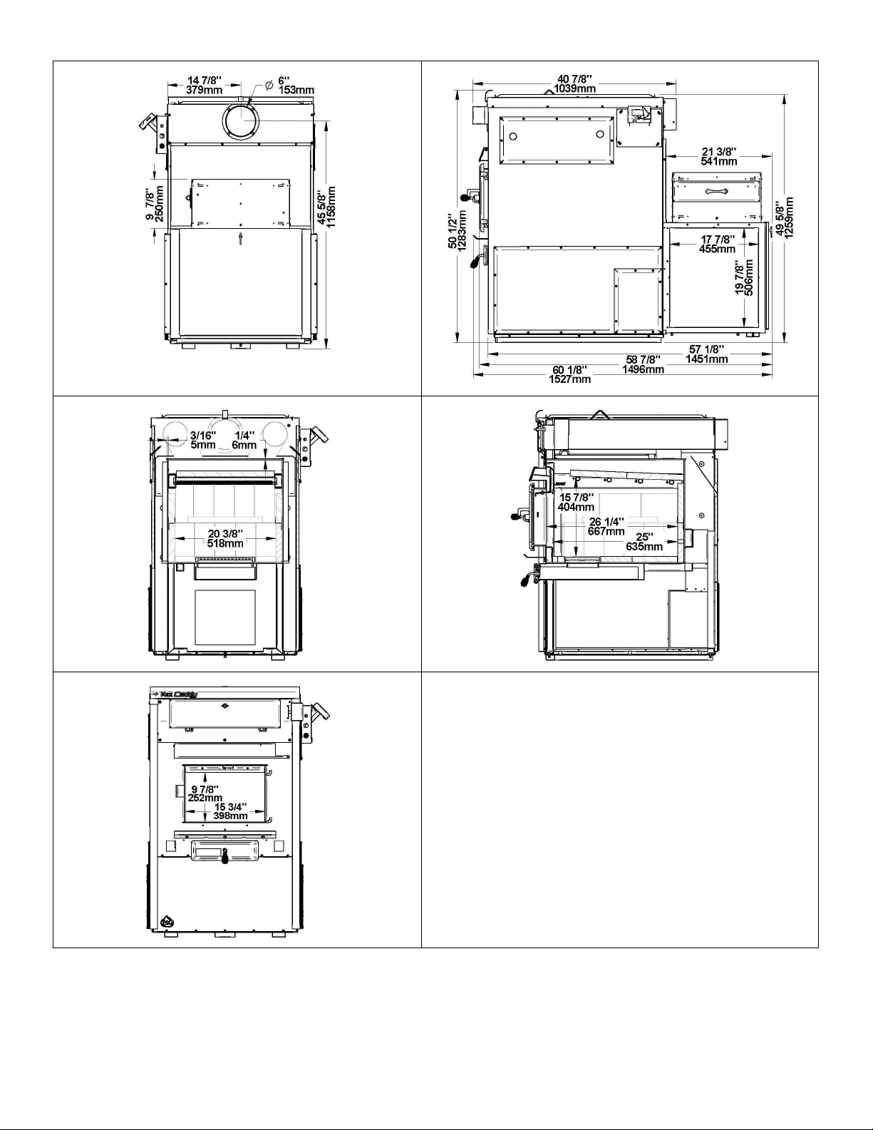
6. FURNACE DIMENSIONS ........................................................................................................................................................... 9
7. CHIMNEY AND DRAFT ............................................................................................................................................................ 11
8. SAFETY RULES ....................................................................................................................................................................... 11
8.1.
GENERAL REQUIREMENTS .......................................................................................................................................... 11
8.2.
ODOUR FROM THE PAINT ............................................................................................................................................. 11
8.3.
ASH DISPOSAL ............................................................................................................................................................... 11
8.4.
CREOSOTE BUILD-UP AND REMOVAL......................................................................................................................... 11
8.5.
SMOKE DETECTOR ....................................................................................................................................................... 12
8.6.
DOOR GLASS ................................................................................................................................................................. 12
8.6.1. GLASS SPECIFICATIONS .............................................................................................................................................. 12
8.7.
ASH DRAWER ................................................................................................................................................................. 12
8.8.
ASH GRATE .................................................................................................................................................................... 12
MAX CADDY WOOD ONLY FURNACE, COMBINED WOOD / ELECTRIC OR PARALLEL ADD-ON PF01102 ............................ 13
9. INSTALLATION INSTRUCTIONS ............................................................................................................................................ 14
9.1.
BLOWER INSTALLATION ............................................................................................................................................... 14
9.2.
LINK BOARD INSTALLATION AND CONNECTION ........................................................................................................ 14
9.3.
TOUCHSCREEN INSTALLATION AND CONNECTION .................................................................................................. 18
9.4.
HOT AIR PLENUM TEMPERATURE PROBE INSTALLATION AND CONNECTION (RTD) ............................................ 19
9.5.
SERVOMOTOR INSTALLATION AND CONNECTION.................................................................................................... 20
9.6.
UNIT LOCATION ............................................................................................................................................................. 21
9.7.
MINIMUM CLEARANCES TO COMBUSTIBLE MATERIALS AND FLOOR PROTECTION ............................................. 21
9.7.1. MINIMUM CLEARANCES TO COMBUSTIBLE MATERIALS .......................................................................................... 22
9.7.2. MINIMUM CLEARANCES TO COMBUSTIBLES MATERIALS FOR AIR RETURN DUCT ............................................... 23
9.7.3. MINIMUM CLEARANCES TO COMBUSTIBLES MATERIALS FOR HOT AIR PLENUM ................................................. 23
9.7.4. FLOOR PROTECTION .................................................................................................................................................... 23
9.8.
FLUE AND BAROMETRIC DRAFT CONTROL CONNECTION ....................................................................................... 24
9.9.
ELECTRICAL CONNECTIONS ....................................................................................................................................... 25
9.10. DAMPER ......................................................................................................................................................................... 25
9.11. COMBUSTION AIR AND FRESH AIR INTAKE ADAPTER INSTALLATION (OPTIONAL) ............................................... 25
9.12. HOT AIR PLENUM ........................................................................................................................................................... 26
9.13. PARALLEL INSTALLATION (US ONLY) .......................................................................................................................... 26
9.14. ELECTRICAL ELEMENT INSTALLATION (OPTIONAL).................................................................................................. 29
9.14.1. INTRODUCTION ............................................................................................................................................................. 29
9.14.2. CONNECTING THE ELECTRICAL ELEMENT ................................................................................................................ 29
10. THERMOSTAT INSTALLATION .............................................................................................................................................. 30
10.1. WOOD FURNACE ONLY................................................................................................................................................. 30
10.1.1. COMBINATION WOOD-ELECTRIC OR WOOD-OIL FURNACE ..................................................................................... 30
10.1.2. COMBINATION WOOD-ELECTRIC-OIL ......................................................................................................................... 30
10.2. INSTALLATION OF AN AIR CONDITIONING UNIT ......................................................................................................... 31
10.3. HEATPUMP INSTALLATION ........................................................................................................................................... 31
10.4. INSTALLATION OF A DOMESTIC WATER PRE-HEATING SYSTEM OR A HUMIDIFIER ............................................. 32
11. CONFIGURATION AND OPERATING INSTRUCTIONS ......................................................................................................... 32
11.1. CONTROLS SYSTEM ..................................................................................................................................................... 32
11.2. SYSTEM CONFIGURATION ........................................................................................................................................... 33
11.3. TOUCH SCREEN ............................................................................................................................................................ 33
11.3.1. ICONS DESCRIPTION .................................................................................................................................................... 33
11.3.2. LANGUAGE SELECTION AND TEMPERATURE UNIT................................................................................................... 34
11.4. ADDING AUXILIARY HEATING SOURCE AND SELECTION OF OPTIONS ................................................................... 34
11.4.1. TRANSITION TO AN AUXILIARY HEAT SOURCE .......................................................................................................... 34
11.4.2. TRANSITION SETTINGS ................................................................................................................................................ 34
11.4.3. AUXILIARY HEAT SOURCE PRIORITIZATION .............................................................................................................. 35
11.4.4. EXTERNAL TEMPERATURE PROBE ............................................................................................................................. 35
11.4.4.1. “BI-ENERGY” FUNCTION ............................................................................................................................................... 35
11.5. DISTRIBUTION BLOWER SPEED CONFIGURATION ................................................................................................... 36
11.5.1. DISTRIBUTION FAN SPEEDS ........................................................................................................................................ 36
11.6. SYSTEM BALANCING .................................................................................................................................................... 36
11.7. OPERATING INSTRUCTIONS ........................................................................................................................................ 37
11.7.1. HEAT M
2
ODE
..................................................................................................................................................................... 37
(1)
................................................................................................................................................ 6
Page 3

11.7.2. COOL M
11.7.3. CIRC M
11.8. WOOD HEATING ............................................................................................................................................................ 38
11.8.1. LIGHTING ........................................................................................................................................................................ 38
11.8.2. PREHEATING ................................................................................................................................................................. 38
11.8.3. HEATING ......................................................................................................................................................................... 38
11.8.4. EARLY SIGNS OF AN OVERFIRED FURNACE: ............................................................................................................. 38
11.8.5. WOOD AS HEATING FUEL ............................................................................................................................................. 39
11.8.6. PROLONGED POWER FAILURE .................................................................................................................................... 39
11.8.7. CHIMNEY FIRES ............................................................................................................................................................. 39
11.8.8. LOCAL FIRE DEPARTMENT ........................................................................................................................................... 39
12. MAINTENANCE ........................................................................................................................................................................ 40
12.1. MAINTENANCE OF THE EXCHANGERS ....................................................................................................................... 40
12.2. CHIMNEY MAINTENANCE ............................................................................................................................................. 41
12.3. SMOKE PIPE INSPECTION ............................................................................................................................................ 41
12.4. BLOWER MOTOR MAINTENANCE ................................................................................................................................ 41
12.5. FILTERS .......................................................................................................................................................................... 41
12.5.1. AIR FILTER DIMENSIONS .............................................................................................................................................. 41
12.6. DOOR GASKET MAINTENANCE .................................................................................................................................... 41
12.6.1. DOOR ADJUSTMENT PROCEDURE ............................................................................................................................. 41
13. REPLACEMENT PARTS .......................................................................................................................................................... 42
13.1. DOOR GLASS ................................................................................................................................................................. 42
13.2. GASKET .......................................................................................................................................................................... 42
14. TROUBLESHOOTING .............................................................................................................................................................. 42
14.1. VALIDATING STATUS OF A COMPONENT .................................................................................................................... 43
14.1.1. DISTRIBUTION BLOWER ............................................................................................................................................... 43
14.1.2. AIR DAMPER, HOT WATER AND HUMIDIFIER .............................................................................................................. 43
14.1.3. TEMPERATURE PROBE (RTD) ...................................................................................................................................... 44
14.2. MAIN ERROR CODES, POSSIBLE CAUSES AND SOLUTIONS .................................................................................... 44
14.2.1. UNIT OVERHEAT ............................................................................................................................................................ 44
14.2.2. NO HEAT ......................................................................................................................................................................... 45
14.2.3. COMMUNICATION ERROR ............................................................................................................................................ 45
14.2.4. SMOKE SMELL ............................................................................................................................................................... 46
14.2.5. THE LCD TOUCH SCREEN DOES NOT LIGHTUP. ........................................................................................................ 46
14.2.6. AUXILIARY OVERRIDE .................................................................................................................................................. 46
15. GENERAL ELECTRICAL DIAGRAM ....................................................................................................................................... 47
16. ELECTRICAL DIAGRAM FOR PARALLEL FURNACE .......................................................................................................... 48
17. ELECTRICAL DIAGRAM FOR ELECTRIC UNIT ..................................................................................................................... 49
WOOD/OIL COMBINATION FURNACE ............................................................................................................................................ 50
18. GENERAL NOTES ................................................................................................................................................................... 52
19. DRAFT AND CHIMNEY ............................................................................................................................................................ 52
20. OIL TANK AND PIPING ........................................................................................................................................................... 52
21. BURNER PUMP........................................................................................................................................................................ 52
22. APPLIANCE INSTALLATION .................................................................................................................................................. 53
22.1. UNIT LOCATION ...................................................................................................................................................................... 53
22.2. PARALLEL INSTALLATION .................................................................................................................................................... 53
22.3. MINIMUM CLEARANCES TO COMBUSTIBLE MATERIALS ................................................................................................. 53
22.4. FLOOR PROTECTION ............................................................................................................................................................. 54
22.5. HOT AIR PLENUM ................................................................................................................................................................... 54
22.6. CONNECTING PIPE AND MANUAL DAMPER ....................................................................................................................... 54
22.7. DIFFERENT INSTALLATION ................................................................................................................................................... 55
22.8. COMBUSTION AIR................................................................................................................................................................... 56
22.9. ELECTRICAL WIRING ............................................................................................................................................................. 56
22.10.
THERMOSTAT ................................................................................................................................................................ 56
23. OPERATION INSTRUCTION ................................................................................................................................................... 56
23.1. FAN SPEED CONTROL ........................................................................................................................................................... 56
23.2. COMBUSTION SAFETY CONTROL ........................................................................................................................................ 56
23.3. PRE-PURGE ............................................................................................................................................................................. 56
23.4. SAFE OPERATION .................................................................................................................................................................. 56
ODE
..................................................................................................................................................................... 37
ODE (AIR CIRCULATION
) ........................................................................................................................................... 37
3
Page 4

23.5. TEMPORARY DISENGAGEMENT OF THE BURNER ............................................................................................................ 56
23.6. COMBUSTION ADJUSTMENT AND VERIFICATION ............................................................................................................. 57
23.6.1. COMBUSTION VERIFICATION PROCEDURE: .............................................................................................................. 57
23.6.2. ELECTRODES SETTING ................................................................................................................................................ 58
23.7. APPLIANCE START-UP .......................................................................................................................................................... 59
23.8. PROLONGED CLOSING .......................................................................................................................................................... 59
24. TECHNICAL DATA ................................................................................................................................................................... 59
24.1. UH –MAX CADDY .................................................................................................................................................................... 59
25. MAINTENANCE ........................................................................................................................................................................ 59
25.1. MAINTENANCE ........................................................................................................................................................................ 59
25.2. SERVICE .................................................................................................................................................................................. 60
25.3. FILTERS ................................................................................................................................................................................... 60
26. ELECTRICAL DIAGRAM BECKETT OIL UNIT ....................................................................................................................... 61
27. ELECTRICAL DIAGRAM RIELLO OIL UNIT ........................................................................................................................... 62
28. LINK BOARD OPTIONS CONNECTIONS ............................................................................................................................... 63
28.1. ELECTRICAL CONSUMPTION ................................................................................................................................................ 63
28.2. OUTDOOR PROBE .................................................................................................................................................................. 63
28.3. HOT WATER ............................................................................................................................................................................ 63
28.4. 24V ADDITIONNAL EQUIPMENT ............................................................................................................................................ 64
28.5. AIR CONDITIONNING DAMPER.............................................................................................................................................. 64
28.6. HUMIDIFIER ............................................................................................................................................................................. 64
28.7. HEAT PUMP ............................................................................................................................................................................. 65
29. EXPLODED VIEW AND PART LIST ........................................................................................................................................ 65
PSG LIMITED LIFETIME WARRANTY (REGULAR) ......................................................................................................................... 78
PSG LIMITED LIFETIME WARRANTY (PRIVILEGE) ....................................................................................................................... 79
4
Page 5

IMPORTANT NOTE:
THE INSTALLATION OF THIS CENTRAL HEATING SYSTEM MUST BE PERFORMED BY A
QUALIFIED TECHNICIAN. PSG RESERVES ITSELF THE RIGHT TO VOID ITS WARRANTY
OR DENY TECHNICAL ADVICE IF THE FURNACE HAS NOT BEEN SOLD OR INSTALLED BY
A PROFESSIONAL.
REGISTER YOU WARRANTY ONLINE
To receive full warranty coverage, you will need to show evidence of the date
you purchased your furnace. Keep your sales invoice. We also recommend
that you register your warranty online at
http://www.caddyfurnaces.com/en/warranty/warranty-registration
Registering your warranty online will help us track rapidly the information we
need on your furnace.
WARNING : THE INSTALLATION OF THIS APPLIANCE REQUIRES THE ADDITION OF A BLOWER ASSEMBLY
(PA08566) NOT INCLUDED.
1. INTRODUCTION
Take note that this furnace operates like an EPA wood burning stove. This applies to the lighting, the ember bed, and
the minimum combustion air intake which was determined based on the use of good seasoned cordwood.
The Max Caddy furnace was tested and approved according to the CSA B415.1-10 Standard.
To optimize the efficiency of your furnace, here is some advice that you should follow when installing or operating your
Max Caddy.
• Respect the local codes (when in doubt, consult your local dealer);
• Make sure your furnace is installed according to the instructions on the certification label;
• All controls and adjustments must be performed by a qualified technician. The blower speed must conform to
the recommendations of local codes and should respect the static pressure ranges in the warm air plenum of
the furnace.
We recommend that our wood burning hearth products be installed and serviced by professionals who are certified in
the United States by NFI (National Fireplace Institute®) or in Canada by WETT (Wood Energy Technical Training) or in
Quebec by APC (Association des Professionnels du Chauffage).
5
Page 6

2. APPLIANCE PERFORMANCE
[*]
[*]
(2)
(3)
(4)
(5)
(6)
(7)
(8)
(5)
(6)
(9)
(10)(11)
(12)
(13)
(1)
(2)
(3)
(4)
(5)
(6)
(7)
(8)
(9)
(10)
(11)
(12)
(13)
(1)
Fuel type Dry cordwood
Recommended heating area
1,500 to 3,500 ft² (139 to 325 m²)
Firebox volume 4.9 ft³ (0.139 m³)
Maximum burn time
Maximum input capacity (dry cordwood)
Overall heat output rate (min. to max.)
17 h
421,000 BTU
19,243 BTU/h to 67,069 BTU/h (5.6 kW to 19.6 kW)
Nominal heat output at 15lb/ft³ fuel loading density 100,000 BTU/h
Average overall efficiency
Delivered heat output rate (min. to max.)
Average delivered efficiency
Optimum efficiency
Average particulate emissions rate
Average CO
13.67 lb/mmBTU (5.88 g/MJ)
Average electrical power consumption
[*]
Recommended heating area and maximum burn time may vary subject to location in home, chimney draft, heat loss factors,
climate, fuel type and other variables. The recommended heating area for a given appliance is defined by the manufacturer as its
capacity to maintain a minimum acceptable temperature considering that the space configuration and the presence of heat
distribution systems have a significant impact in making heat circulation optimum.
Values are as measured per CSA B415.1-10, except for the recommended heating area, firebox volume, maximum burn time
and maximum input capacity. Performances based on a fuel load prescribed by the standard at 10 lb/ft³ and with moisture
content between 18% and 28%.
Input value at 10lb/ft³ fuel loading density and dry energy value of 8,600BTU/lb.
Overall: Radiated and delivered heat together at10lb/ft³ fuel loading density over one total burn cycle.
Efficiency based on delivered heat when allowing cycling from high to low burn to simulate thermostat demand.
Higher Heating Value of the fuel.
Lower Heating Value of the fuel.
78.9% (HHV)
16,109 BTU/h to 54,578 BTU/h (4.7 kW to 16.0 kW)
64.8% (HHV)
85.8%
0.735 lb/mmBTU (0.316 g/MJ)
360 Wh
85 % (LHV)
70.2% (LHV)
Delivered: Remotely provided to other rooms through ducting at 10 lb/ft³ fuel loading density over one total burn cycle.
Efficiency based on radiated and delivered heat when allowing cycling from high to low burn to simulate thermostat demand.
Optimum overall efficiency at a specific burn rate (LHV).
Based on delivered heat output.
This appliance is officially tested and certified by an independent agency.
Carbon Monoxyde. Based on overall heat output at 10lb/ft³ fuel loading density.
Unless stated otherwise, measures were taken directly at the main power source and include all electrical components present in
the appliance.
6
Page 7

3. GENERAL FEATURES
Maximum log length 25 in (635 mm) / north-south*
Diameter of the flue collar 6 in (152 mm)
Recommended connector pipe diameter 6 in (152 mm) if installed as wood only or combined wood-electric
Mandatory connector pipe diameter 7 in (178 mm) if installed as combined wood-oil
Recommended chimney diameter
Mandatory chimney diameter 7 in (178 mm) if installed as combined wood-oil
Required type of chimney CAN/ULC S629, UL 103 HT (2100 °F)
Baffle material C-Cast
Add-on installation US only
Alcove installation Not approved
Mobile home installation‡ Not approved
Appliance weight (without option) 614 lb (279 kg)
Shipping weight (without option) 729 lb (331 kg)
Blower (wood or wood/electric options only) 1/2 HP, direct drive, 4 speeds, 2,100 CFM
Filter – dimensions (Width x Depth x Height)
(included with optional blower assembly)
Filter – quantity 1
Particulate emission standard EPA / CSA B415.1-10
USA standard (safety)
Canadian standard (safety)
6 in (152 mm) if installed as wood only or combined wood-electric
16 in x 20 in x 1 in (406 mm x 508 mm x 25 mm)
UL 391, UL 1995, UL 727
CSA B366.1, CSA C22.2 no 236, CAN/CSA B140.4
** East-west: through the door you see the longitudinal sides of the logs; north-south: through the door you see the tips of the logs.
‡
Mobile home (Canada) or manufactured home (USA): The US department of Housing and Urban Development describes
“manufactured homes” better known as “mobile homes” as followed; buildings built on fixed wheels and those transported on
temporary wheels/axles and set on a permanent foundation. In Canada, a mobile home is a dwelling for which the manufacture and
assembly of each component is completed or substantially completed prior to being moved to a site for installation on a foundation
and connection to service facilities and which conforms to the CAN/CSA-Z240 MH standard.
7
Page 8

4. SPECIFICATIONS
Color Grey
Thermostatic control Yes
Door type Single, glass with cast iron frame
Glass type Ceramic glass
Air return plenum – dimensions (Depth or Height) 17 15/16 in
Air return plenum – dimension (Width) 19 15/16 in
Hot air plenum – dimensions (Depth or Height) 32 1/8 in
Hot air plenum – dimension (Width) 25 3/8 in
Ash pan – dimensions (Width x Depth x Height) 11 15/16 in x 19 5/8 in x 2 5/8 in
Clearance – front 48 in
Clearance – back wall 24 in from the blower housing recommended service clearance
Clearance – side wall 6 in without options installed
Clearance – opposite side wall 24 in recommended service clearance
Clearances – ducts 6 in for the first 6 feet with heat shield and 1 in after
Clearance – recommended for maintenance on
option side
Burner – efficiency Beckett AFG : 85 % / Riello : 87%
Burner – standard Beckett AFG
Burner – other brands approved Riello
Burner – location Left or right
Burner – recommended clearance for maintenance 24 in
Burner – mandatory connector pipe diameter
(Wood-oil)
Burner – mandatory exhaust pipe diameter 5 in
Burner – location of exhaust pipe Left or right
Burner – capacity at input #1 / #2 Beckett 91,000 BTU (27 kW) / 120,000 Btu (35 KW)
Burner – orifice at input #1 / #2 Beckett 0,65 gal/h* 70° W (2,46 l/h) for both inputs
Burner – pump pressure at input #1 / #2 Beckett 100 PSI / 175 PSI
Burner – capacity at input #1 / #2 Riello 91,000 BTU (27 kW) / 120,000 Btu (35 KW)
Burner – orifice at input #1 / #2 Riello 0.50 gal/h* 70° W (1.89 l/h) / 0.65 gal/h* 70° W (2.46 l/h)
Burner – pump pressure at input #1 / #2 Riello 150 PSI / 165 PSI
Electric element – location Left or right
Electric element – clearance recommended for
maintenance
Electric element – recommended (maximum
output)
Electric element – other optional (maximum output) 25 kW
Top cold air plenum option – material Galvanized steel
Top cold air plenum option – dimensions
(Width x Depth x Height)
Top cold air plenum option – smoke pipe diameter 6 in
Fresh air intake adapter option 5 in
Fresh air intake adapter – connection location Left or right
Fresh air intake adapter – connecting pipe
diameter
Tested and listed as per applicable standards By an accredited laboratory (CAN/USA)
Warranty
24 in
7 in
24 in
20 kW
20 in x 18 in x 17 1/4 in
6 in
Limited lifetime
* US Gallon (1 US Gallon = 0,83 Imperial Gallon)
8
Page 9

5. MAX CADDY FURNACE TECHNICAL DATA
WOOD AND WOOD/ELECTRIC
WOOD/OIL
MODEL (DIRECT DRIVE)
VENT MOT. VIT. (CFM) (OF) MIN. MAX. (1)
INCH H2O
MAX CADDY WITH
BLOWER / MAX CADDY
ADD-ON (PARALLEL)
G-10 1/2 4 2,100 100 0,2 0,5 16" x 20" x 1"
6. FURNACE DIMENSIONS
THEORETICAL
DEBIT
TEMP
VAR.
STATIC PRESSURE FILTER
9
Page 10
10
Page 11

7. CHIMNEY AND DRAFT
This furnace must be connected to a chimney certified for use with wood burning heating appliances. A 7-inch chimney
and connector must be installed for the Max Caddy if it is used as a wood-oil unit, a wood-electrical-oil unit or if an oil
option may be installed in the future. If the furnace is to be used as a wood only unit or a wood-electric, then a 6-inch
chimney is recommended.
The unit is not to be connected to a chimney flue serving another appliance. If the chimney draft exceeds 0.06 IN.W.C.,
a barometric draft control should be installed on the smoke pipe. Never install a manual damper. The barometric
control must be adjusted so that the maximum draft measured at the furnace outlet does not exceed -0.06 IN.W.C.
Please note that a draft exceeding 0.06 IN.W.C. could produce an uncontrollable fire. On the other hand, the
minimum draft required is 0.04 IN.W.C. in the evacuation pipe on the wood side, no matter what type of furnace
(WOOD, WOOD/ELECTRIC OR WOOD/OIL). The adjustment should in no case be modified to increase
combustion.
8. SAFETY RULES
WARNING:
THE INFORMATION GIVEN ON THE CERTIFICATION LABEL AFFIXED TO THE APPLIANCE ALWAYS
OVERRIDES THE INFORMATION PUBLISHED, IN ANY OTHER MEDIA (OWNER’S MANUAL, CATALOGUES,
FLYERS, MAGAZINES AND/OR WEB SITES).
8.1. GENERAL REQUIREMENTS
MAKE SURE THE CHIMNEY OUTLET AND THE PIPES ARE CLEAN AND IN GOOD CONDITION.
DO NOT USE CHEMICAL PRODUCTS OR LIQUIDS TO LIGHT THE FIRE.
DO NOT BURN WOOD COATED WITH PAINT, GLUE OR CHEMICAL PRODUCTS.
DO NOT BURN WASTES OR FLAMMABLE LIQUIDS SUCH AS GASOLINE, NAPHTHA, MOTOR OIL, OR OTHER
UNSUITABLE MATTERS.
DO NOT STORE WOOD IN THE VICINITY OF THE FURNACE. RESPECT THE REQUIRED CLEARANCES
BETWEEN COMBUSTIBLE MATERIALS AND THE SOURCE OF HEAT.
WARNING
THE ASH DRAWER AND EXCHANGERS ACCESS PANEL GET VERY HOT. DO NOT MANIPULATE
WITH BARE HANDS.
8.2. ODOUR FROM THE PAINT
It is normal that smoke and odours emanate from the unit when you first light it. It is recommended to burn it at high
rate and ventilate the building until the odours disappear. The smoke is not toxic. This should be done before the
ducts are connected to the furnace to prevent smoke dispersion in the house.
8.3. ASH DISPOSAL
Ashes must be placed in a metal container with a tight fitting lid. The container should be stored outdoor, well away
from combustible materials. This container should not contain any other type of waste. If the ashes are meant to be
buried in soil, wait until all embers have thoroughly cooled before burying.
8.4. CREOSOTE BUILD-UP AND REMOVAL
When wood is burned slowly, it produces tar and other organic vapours which, when combined with moisture, form
creosote. The creosote vapours condensate in a relatively cool chimney flue. As a result, creosote residues
accumulate inside the flue lining and the exchangers.
N.B.: To minimize the frequency of the chimney cleaning, buy your firewood at least one year before using it. Store it
in a dry place in order to obtain the minimum moisture rate and optimize the efficiency. Do not store wood or
combustible materials within the installation minimum clearances or the space required to reload the appliance and
remove ashes.
11
Page 12

When ignited, creosote produces an extremely hot fire inside the chimney.
In the first year of use, inspect the chimney system at regular intervals to determine a cleaning cycle. Depending on
the type of wood used and its quality, a semi-annual cleaning may be required. A yearly cleaning is mandatory. If a
significant layer of creosote has accumulated, it must be removed immediately to eliminate the risk of chimney
fire.
Remember that a small, hot fire is preferable to a large smouldering one to prevent creosote build-ups within the
system. Prepare an emergency procedure in case of a chimney fire. It is recommended to clean the heat
exchangers thoroughly at the end of season in order to prevent corrosion.
8.5. SMOKE DETECTOR
We highly recommend the use of a smoke detector. It must be installed at least 15 feet (4,57 m) from the appliance in
order to prevent undue triggering of the detector when reloading.
8.6. DOOR GLASS
To maintain a clean and safe installation, do not build your fire too close to the glass or allow logs to lean on the glass.
Do not operate your furnace at too low a setting. Keep the air inlet opened long enough during the fire start-up to
prevent the fire from smouldering, which could stain the glass.
An intense fire will help keep the glass clean. However, in the event that your glass gets stained, which should not
occur under normal operating conditions, you will have to clean it using a wet cloth and a fireplace glass cleaner. Clean
the glass ONLY when the unit has cooled down. Do not use abrasive cleanser.
WARNING: Avoid knocking or scratching the glass. It could crack or break.
8.6.1. GLASS SPECIFICATIONS
The glass is made of 3/16" (5mm) thick ceramic glass.
Do not operate your wood furnace with a broken glass, as this could seriously damage your furnace.
You can purchase a replacement glass from your PSG dealer.
8.7. ASH DRAWER
Your furnace is equipped with an ash drawer to collect ashes produced by the combustion of wood. This drawer must
not be left open during combustion as this may cause over firing and serious damages to the furnace. Moreover, the
additional air created could cause the dispersion of ashes in the ventilation system. The drawer must be cleaned
regularly. Use a vacuum cleaner to remove any ashes around the drawer in order to avoid the dispersion of
ashes in the ventilation system.
It is important that the door and the ash drawer be kept closed while the appliance is in use.
Maintain all gaskets in good condition; in case of deterioration, contact your dealer for a genuine
replacement gasket.
8.8. ASH GRATE
You must replace the ash grate if it is damaged and a replacement may be obtained from your dealer.
12
Page 13
INSTALLATION AND OPERATION
MAX
CADD
Y FURNACE
– WOOD ONLY
MAX CADDY
FURNACE
– COM
BINED
INSTRUCTIONS FOR
MAX CADDY WOOD ONLY FURNACE,
COMBINED WOOD / ELECTRIC OR
PARALLEL ADD-ON (US ONLY)
PF01102
WOOD/ELECTRIC
13
Page 14
9. INSTALLATION INSTRUCTIONS
Installation must be made in accordance with the CSA B.365 « Installation code for solid-fuel-burning appliances and
equipment » standard in Canada and NFPA 90B « Standard for the installation of warm air heating and air conditioning
system » in the United States. Moreover, for all electrical connection, the Canadian standard CSA C22.1 « Canadian
electrical code » and in the United-States NFPA 70 standard « National Electrical Code » must be followed.
All controls and adjustments must be performed by a qualified technician. The blower speed must conform to the
recommendations of the Warm Air Heating and Air Conditioning National Association and should respect the static
pressure ranges in the warm air plenum of the furnace
We recommend that our woodburning hearth products be installed and serviced by professionals who are certified in
the United States by NFI (National Fireplace Institute®) or in Canada by WETT (Wood Energy Technical Training) or in
Quebec by APC (Association des Professionnels du Chauffage).
Inspect the furnace to make sure that nothing has been damaged in the shipping. Pull out the wiring kit and the
instructions manual from the firebox of the furnace and the accessories from the flue pipe.
The following section contains installation instructions for the Max Caddy wood only, Max Caddy wood / electric and
Max Caddy add-on parallel configurations.
9.1. BLOWER INSTALLATION
To use the wood only configuration, the blower assembly (PA08566 – sold separately) is required. The installation
instructions are provided with the blower.
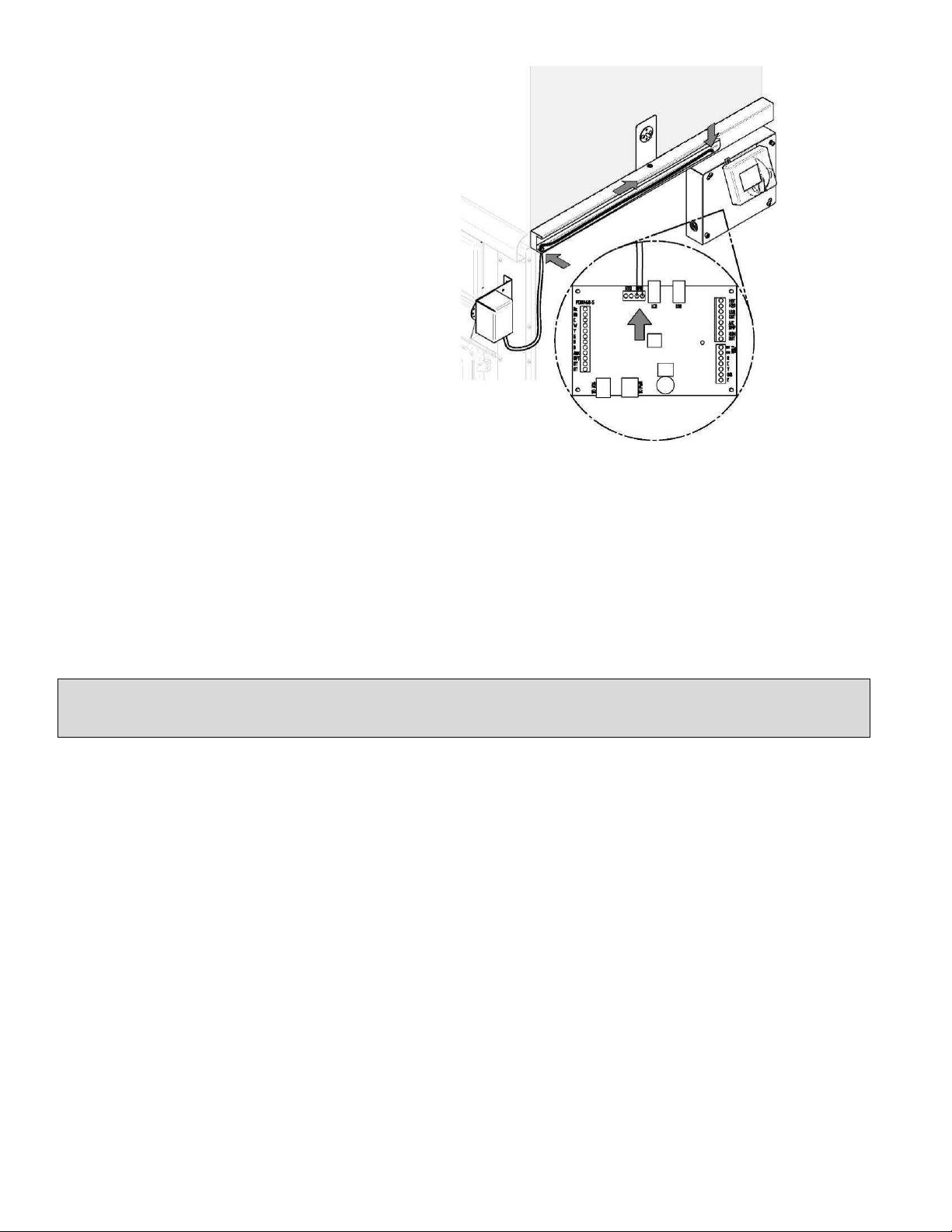
9.2. LINK BOARD INSTALLATION AND CONNECTION
The following installation instructions are identical whether the furnace controls are located on the left or on the right of
the furnace. The most accessible side is preferred to facilitate the connection of auxiliary heating sources or for
servicing.
The components to be installed are in the combustion chamber of the furnace.
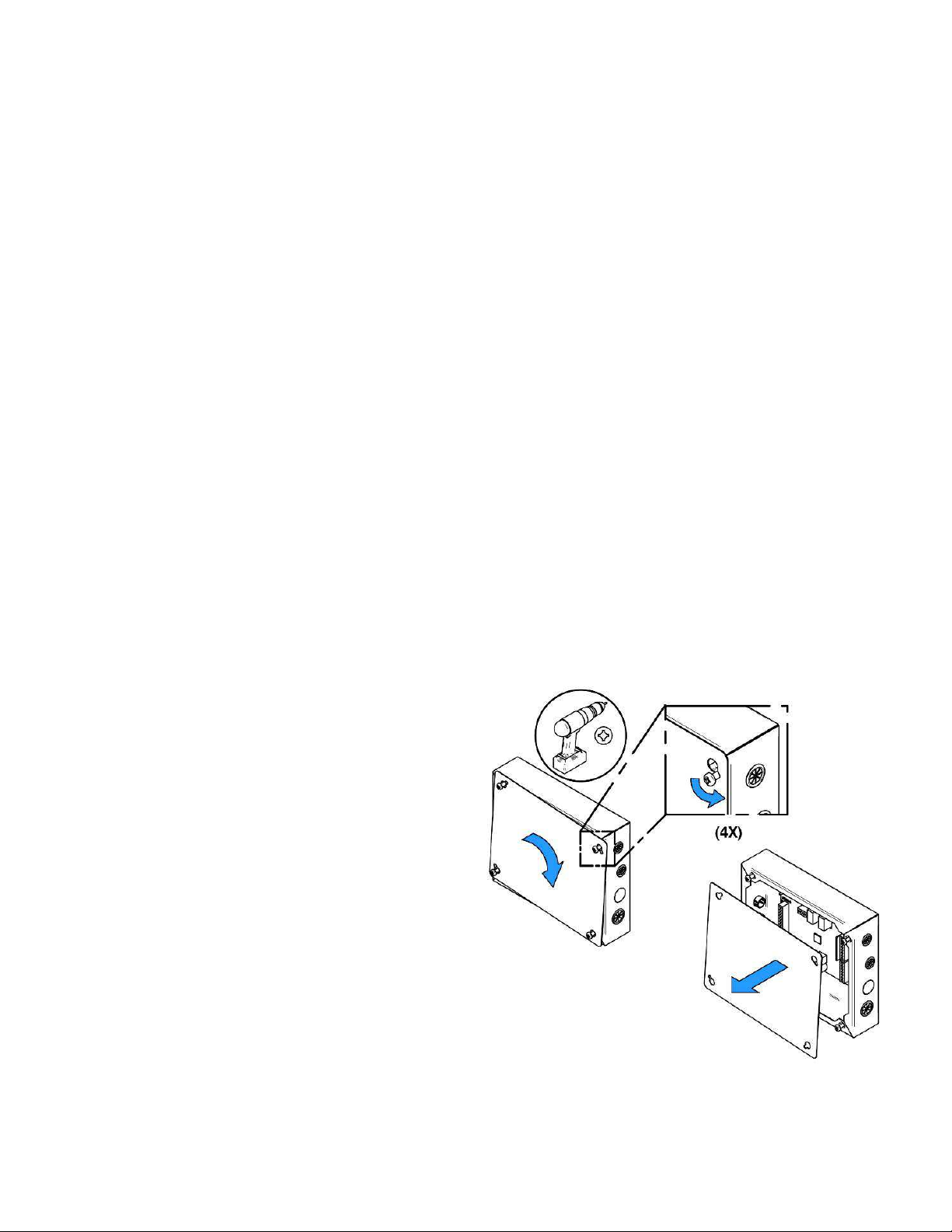
Remove the link board housing cover.
14
Page 15

Remove the four screws on the
furnace, located on the side of the
desired installation.
Align the holes of the board housing
the holes on the side of the furnace.
Use the screws removed in the
previous step to secure the housing to
the furnace.
Once installed, the link board must be
connected to the system with the
telecommunication wire of the power
board. The wire is located in the
blower box. To access it, remove the
air return box.
15
Page 16
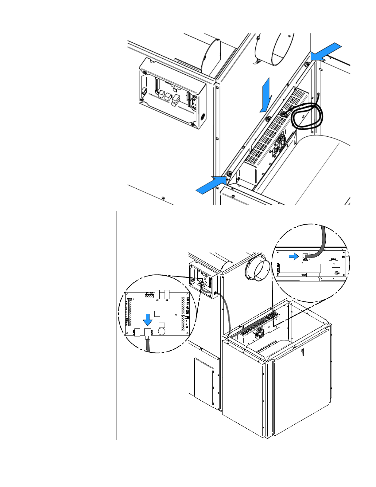
Take the telecommunication
wire and pull it through the
grommet located on the side
where the housing board is
installed.
Once the telecommunication
wire is out on the desired side,
run it along the back of the
furnace and pass it through
the grommet at the bottom of
the link board housing.
Complete the connection by
plugging the 8 strands
telecommunication wire in the
right connector, shown by the
arrow.
16
Page 17
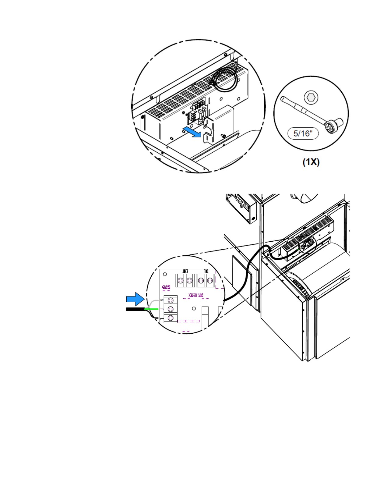
Your furnace should also be
connected to a 115V power
source. To do so, open the
cover of the power board
housing.
Connect the power cord to the
terminals N (Neutral) F
(Ground) L (Line). Refer to
wiring diagram for connecting
components. When done,
secure the wires with a BX
connector (not included) and
replace the blower box cover.
17
Page 18
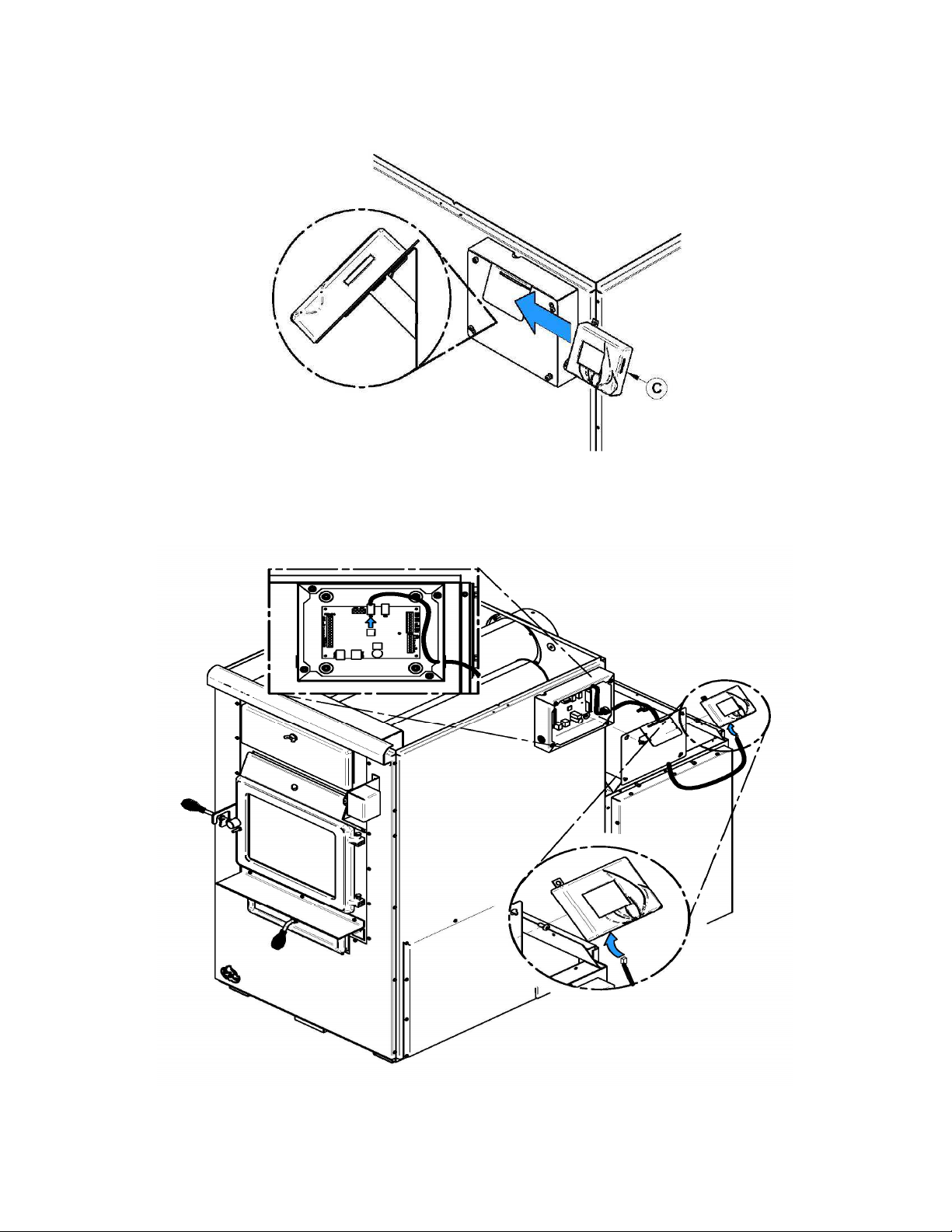
9.3. TOUCHSCREEN INSTALLATION AND CONNECTION
The touch screen is used to operate the system. It must be installed on the support provided at the back of the furnace,
on the same side as the link board housing.
Connect link board with the touch screen using the telecommunication wire provided with the user manual. Plug the
telecommunication wire in connector labeled LCD and pull it out of the board housing through the top grommet. Simply
run the wire on the side of the furnace using the plastic ties supplied with the user manual. Replace the access panel
of the link board. Note that the touch screen is removable if access is restricted.
18
Page 19
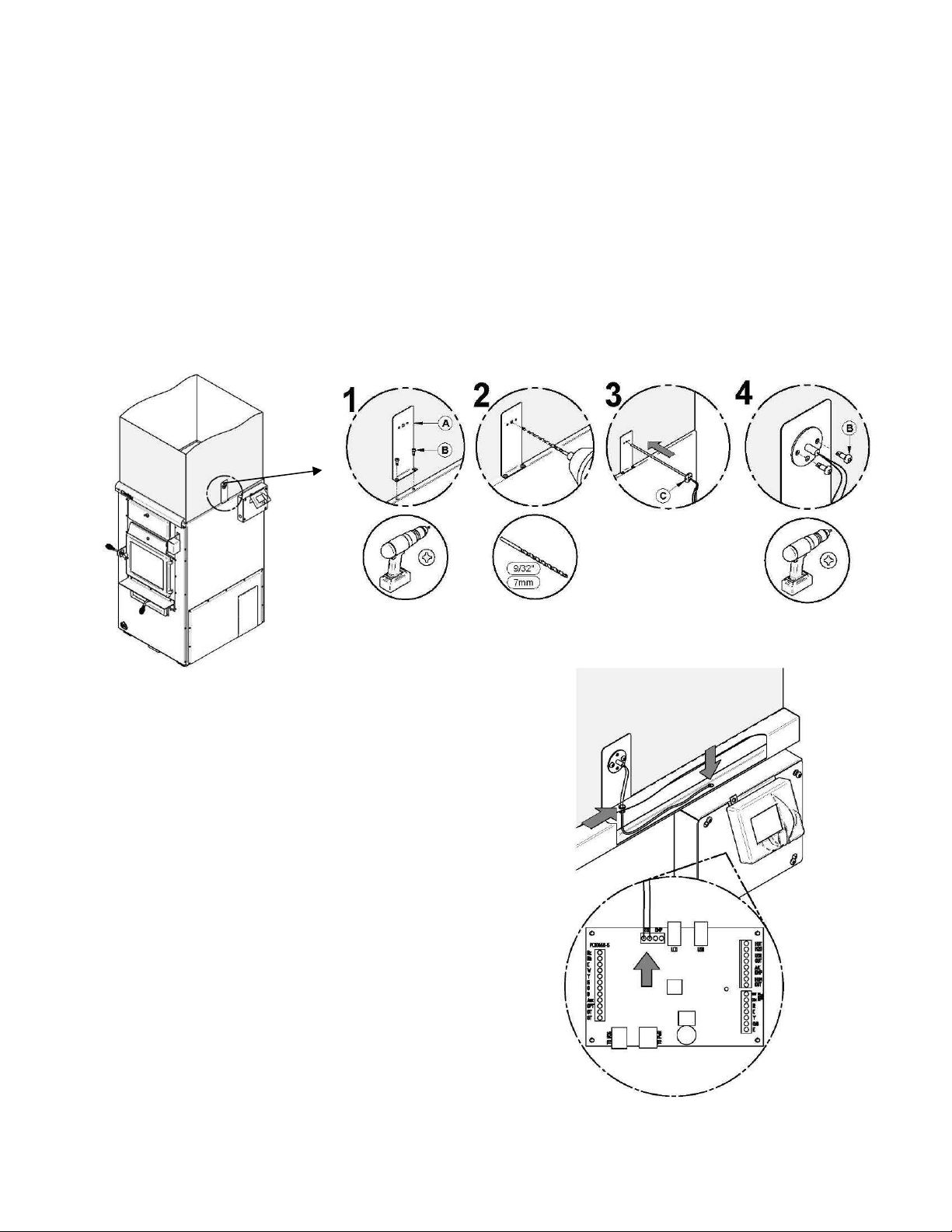
9.4. HOT AIR PLENUM TEMPERATURE PROBE INSTALLATION AND CONNECTION (RTD)
On the Max Caddy, a RTD has to be installed on the side of the furnace using the support provided with the unit. The
RTD is a sensor that reads the temperature inside the hot air plenum. It is critical to the good operation of the furnace.
Refer to electric diagram for connection details. It is important that the RTD and the RTD support be properly fixed onto
the hot air plenum.
WARNING: USE WIRING SUITABLE FOR 75 °C (not included).
STEP 1: Remove the two screws already secured to the furnace (B) on the side where you have chosen to install the
link board. Then, secure the RTD support (A) using the two screws you previously removed.
STEP 2: Using a drill and a 9/32" bit, drill a hole in the hot air plenum so that the RTD rod can pass into it.
STEP 3 and 4: Secure the RTD in place on the hot air plenum using the two self-tapping screws provided with the
owner’s manual.
Once the RTD is installed on the support, proceed to its
connection to the link board. Pass the RTD wires in the
grommet and exit them close to the link board. For board
connections, refer to the wiring diagram.
19
Page 20
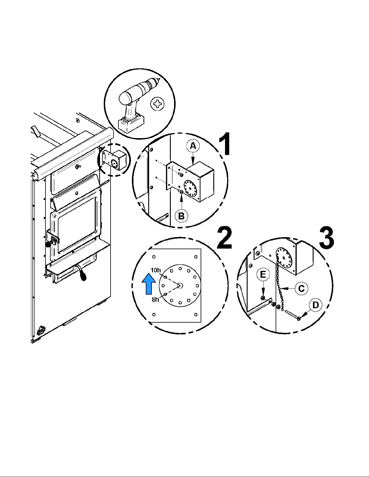
9.5. SERVOMOTOR INSTALLATION AND CONNECTION
Your Max Caddy furnace is equipped with a servomotor. To install it, simply screw it in place in the two pre-drilled holes
in the front of the furnace using two screws as shown below.
Once installed, install the chain linking the servomotor with the air inlet damper as shown above. The chain must have
a set of 1/8". When there is no call for heat, the air inlet damper must be completely closed and the chain must be
hooked to the servomotor at the “8 o’clock” position.
20
Page 21
Then, you must connect the servomotor and the link
board. Take the wires out of the servomotor and enter
the wires in the wire cover through the grommet. Pull
them out through the grommet next to the link board
housing.
For connection, refer to wiring diagram.
WARNING: USE WIRING SUITABLE FOR 75 °C
(not included).
9.6. UNIT LOCATION
For a safe and quiet operation, the furnace must be leveled in both directions and supported evenly to ensure stability.
The furnace must be installed where outside air supply will be sufficient for proper combustion. In airtight houses, it
might be necessary to install an outside air inlet (See Section 9.11 - COMBUSTION AIR AND FRESH AIR INTAKE
ADAPTER INSTALLATION (OPTIONAL))
The furnace must be positioned so that the connector is as short as possible. Minimize the use of 90o elbows.
The owner must ensure a proper installation to allow a safe operation of the appliance.
9.7. MINIMUM CLEARANCES TO COMBUSTIBLE MATERIALS AND FLOOR PROTECTION
N.B.: This appliance must be installed in accordance with the instructions on the certification plate
applied on the unit.
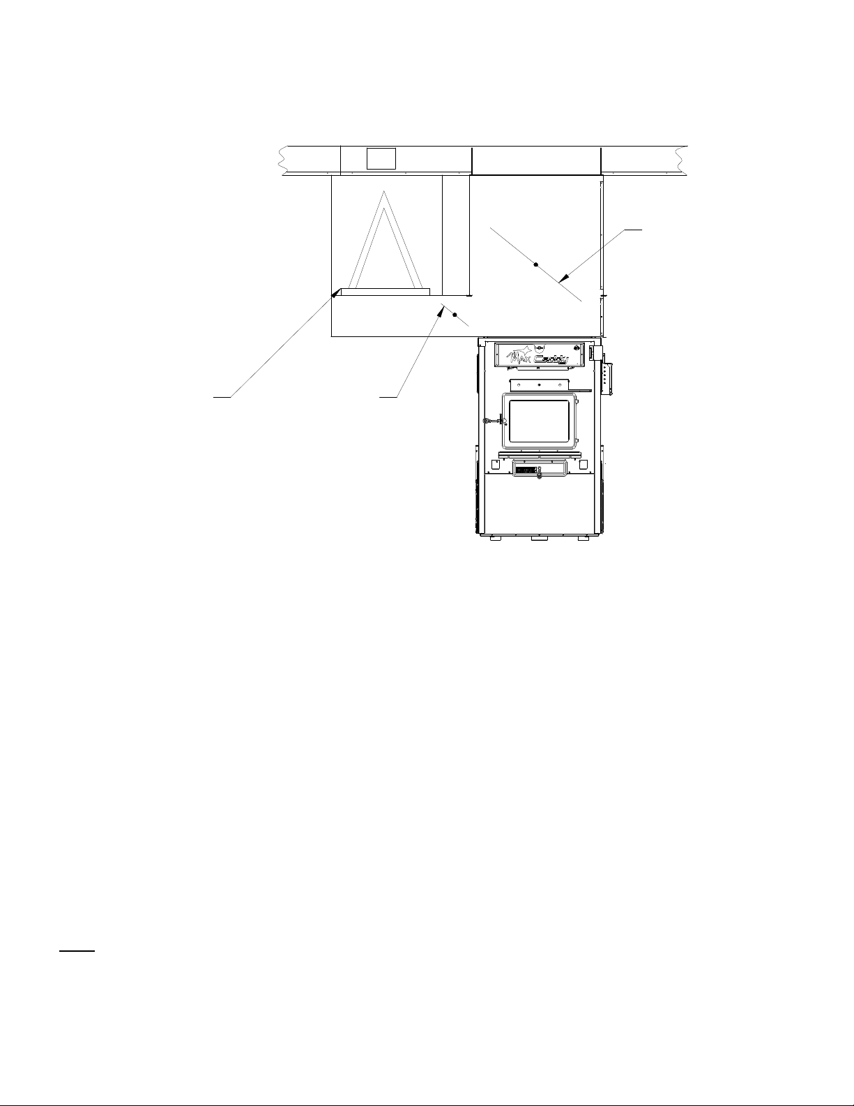
THE INSTALLATION OF THE HEAT SHIELD (-1-) PROVIDED WITH THE FURNACE IS
MANDATORY.
21
Page 22
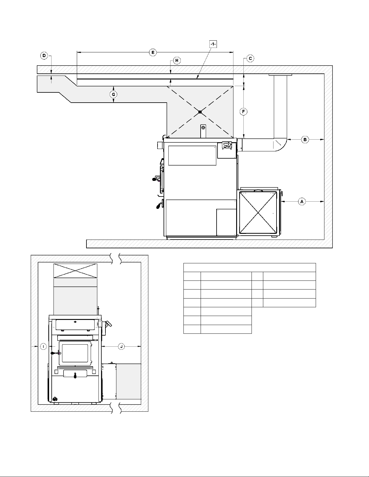
9.7.1. MINIMUM CLEARANCES TO COMBUSTIBLE MATERIALS
MINIMUM CLEARANCES
A
24" (610 mm)
B
18" (458 mm)
C
D
E
F
6" (153 mm)
1" (26 mm)
72" (1 829 mm)
24" (610 mm)
G
8" (204 mm)
H
1 1/2" (38.1 mm)
I
6" (153 mm)
J
24" (610 mm)
-1- HEAT SHIELD
22
Page 23
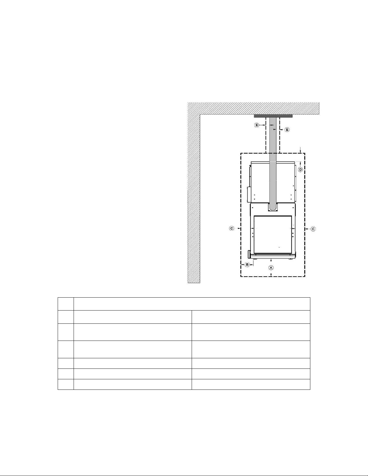
9.7.2. MINIMUM CLEARANCES TO COMBUSTIBLES MATERIALS FOR AIR RETURN DUCT
The return air duct should be at least equal in size to the return air plenum. The air return duct can be installed at zero
clearance to combustibles.
9.7.3. MINIMUM CLEARANCES TO COMBUSTIBLES MATERIALS FOR HOT AIR PLENUM
Plenums installed on the furnace must be made of metal in accordance with CSA B365 or NFPA 90B. The hot air duct
can be passed through the side wall with a clearance of six (6) inches around thereof.
9.7.4. FLOOR PROTECTION
If the floor is made of non combustible material, no
floor protector is required.
If the floor is made of combustible material, a non
combustible material floor protector is required (see
table below).
A
B
C
D
E
*Steel with a minimum thickness of 0.015" (0.38 mm) or ceramic tiles sealed together with grout. No protection is required if the unit
is installed on a non-combustible floor (ex: concrete).
Note 1: The floor protection at the back of the furnace is limited to the furnace’s required clearance (A) if such clearance is smaller
than 8 inches (203 mm).
Note 2: Only required under the horizontal section of the connector. Must exceed each side of the connector pipe by at least 2
inches (51 mm).
CANADA USA
18" (457 mm)
From door opening
N/A (USA only)
8" (203 mm) N/A (Canada only)
8" (203 mm) – Note 1 N/A (Canada only)
N/A (USA only) Note 2
FLOOR PROTECTION*
16" (406 mm)
From door opening
8" (203 mm)
From door opening
23
Page 24
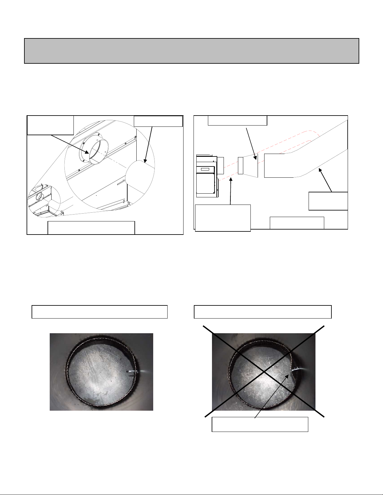
9.8. FLUE AND BAROMETRIC DRAFT CONTROL CONNECTION
removed any accessory from the flue
WOOD ONLY
Diameter
6"
WOOD/OIL
Reducer
7" to 6"
PROPER INSTALLATION
IMPROPER INSTALLATION
Before connecting the stove pipe, make sure you have
pipe such as the scraper, shovel, and the poker.
The flue outlet on the Max Caddy furnace is 6" in diameter and the wood only or wood/electric models may be installed
with a 6" chimney approved for use with wood burning heating appliances (2100°F). However, it is mandatory to use a
7" diameter chimney if the retrofit to a wood/oil configuration is probable. In that case, a 6" to 7" reducer must be
installed at the flue outlet of the furnace. If the draft exceeds 0.06 IN.W.C., a barometric control must installed. Never
install a manual damper. Secure the exhaust pipe to the flue adapter with three screws.
FLUE
ADAPTER
Diameter 7"
Unit oil
OIL UNIT’S
UTLET
Max Caddy pipe
For a proper installation, follow the advice below:
• All the exhaust pipe joints must be secured with three screws.
• Make sure that each screw goes through the inner wall of both connectors (male and female). See pictures below
showing a male-female coupling.
• A minimum rise of ¼" per horizontal foot must be respected.
CAUSES RESTRICTION
24
Page 25

9.9. ELECTRICAL CONNECTIONS
The following instructions do not replace those of the local code.
Installation and verification of this appliance must be done by a qualified service man.
All wiring from the service panel to the heating unit must comply with the electrical code in force and all local
regulations. It is recommended to feed the furnace with its own electrical circuit of 15 amps at 120 volts with a breaker
(see wiring diagram).
9.10. DAMPER
If the draft exceeds 0.06 INW.C., a barometric damper must be installed. The barometric damper must be adjusted so
that the maximum draft measured at the furnace outlet is limited to 0.06 IN.W.C. Please note that a draft higher than
0.06 IN.W.C. will reduce efficiency and could result in an uncontrollable fire. On the other hand, the minimum draft
to be respected is 0.04 IN.W.C. in the evacuation pipe on the wood side, no matter what type of furnace is use
(WOOD, WOOD/ELECTRIC, WOOD/OIL)
9.11. COMBUSTION AIR AND FRESH AIR INTAKE ADAPTER INSTALLATION (OPTIONAL)
When the furnace and the chimney are completely cold, it may be necessary to provide fresh air by opening a door or
a window for a few minutes while lighting the fire. Take note that a house constructed or renovated in order to be
airtight may lack the volume of fresh air necessary for the proper combustion of a solid-fuel heating appliance.
In such a case, when starting up the fire, do not operate appliances that evacuate air outside the house, such as:
- Range hood
- Air exchanger
- Clothes dryer
- Bathroom fan
- Ventilated central vacuum system
A fresh air supply may be necessary to prevent solid fuel units from rejecting products of combustion into the house.
The indications used to determine if an additional fresh air supply is necessary are not appropriate for all the situations.
When in doubt, it is recommended to install a fresh air supply.
A fresh air supply may be needed if:
- Solid fuel units present anomalies, such as irregular draft, smoke return, bad combustion, and/or reversed
draft (whether there is combustion or not);
- Existing solid fuel units such as a stove or fireplace release odours, heat badly, cause smoke returns, or
reversed draft (whether there is combustion or not );
- The opening of a window, even slightly, in calm weather (windless), eliminates every problem mentioned
above ;
- The house is equipped with a tight vapour barrier and adjusted windows, and/or is equipped with an interior
air mechanical evacuation device ;
- There is excessive condensation on the windows in winter; and
- The house is equipped with a ventilation system.
If, according to these symptoms or other similar ones, there is insufficient combustion air, it is necessary to ensure an
additional combustion air supply.
Additional combustion air can be provided with the following methods, provided that they satisfy chapter 5 of the CSA
B365 standard for Canada:
• Direct connection: solid fuel units can be connected directly to a source of new combustion air only if they are
certified for this kind of installation, which must respect the manufacturer’s instructions. The Max Caddy can be
installed with an optional sealed fresh air kit that has been tested with the unit. Consult your dealer.
• Indirect method: new combustion air can be brought into a pipe located within approximately 300mm (12 inches) of
the unit. If the pipe is too close to the furnace, it may interfere with its operation.
• Mechanical ventilation system: if the house is equipped with a ventilation system (air exchanger or heat recovery),
the ventilation system may provide sufficient auxiliary air to the solid fuel unit. Otherwise, the owner should be
informed that the ventilation system may have to be rebalanced by a ventilation technician after the installation of
the solid fuel unit.
25
Page 26

NOTE:
(full length)
entry
It is recommended to install an outside air inlet with
a diameter of at least 4" in the room where the
heating appliance is installed (see drawing below).
It is preferable to choose a wall which is not
exposed to dominant winds, depending on the
conditions surrounding your house.
Fresh air
intake
Exterior wall
N.B. The owner of the furnace is responsible for the room’s air quality in case of negative pressure or
temporary negative pressure.
If there is a fan in the wood storage room, make sure it does not create a depression in the room where the furnace is
installed.
For more information regarding the installation of fresh air intake adapter, refer to the option’s manual.
Insulated pipe
Free air
9.12. HOT AIR PLENUM
The hot air plenum coming out of the furnace is to have a minimum height of 24" (610 mm). These dimensions for all
hot air furnaces are in accordance with the standards CSA B140.4, UL 391 and UL 727.
NOTE: TO ENSURE ADEQUATE STATIC PRESSURE, THE SYSTEM SHOULD BE BUILT IN A WAY THAT THE
VOLUME OF COLD AIR RETURN IS AT LEAST EQUAL OR SLIGHTLY HIGHER THAN THE VOLUME OF THE HOT
AIR DISTRIBUTION.
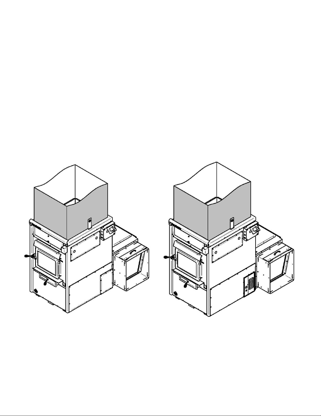
9.13. PARALLEL INSTALLATION (US ONLY)
The installation of the Max Caddy with another furnace using the same ductwork is not allowed in Canada. This type
of installation is only allowed in the United States. Ideally, the maximum BTU input of the existing oil, gas, or
electric furnace should be equal or higher than the maximum BTU input of the wood furnace. It is mandatory to
respect minimum clearances between the ductwork and combustible material as if the wood furnace was installed as a
standalone unit. The ductwork and furnace should be adjusted in order to reach a static pressure of at least 0.20
IN.WC, but not more than 0.50 IN.WC. A back-flow damper should be installed in the plenum. The back-flow damper
assures that when either unit is operated by itself, the hot air will flow into the home, and not back through the other
furnace. Depending on your installation (see figures examples below), a back-flow damper may be required in each
plenum.
CANADA; The installation in parallel i.e. the Max Caddy furnace combined with another, using the same system of hot
air ducts is not allowed in Canada.
UNITED STATES; The installation in parallel i.e. the Max Caddy furnace combined with another, using the same hot
air duct system is allowed the United States.
26
Page 27
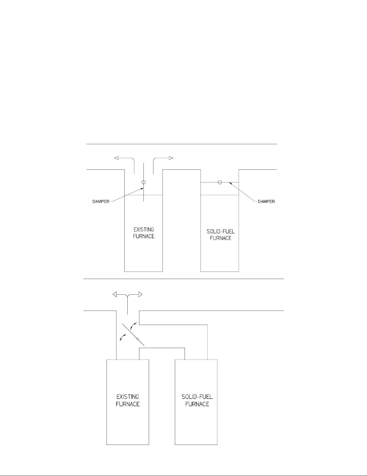
Conditional to;
o The maximum input power of the existing gas, oil or electric furnace should be equal or lower than 120 000
Btu/h.
o The clearances required for wood furnace must be respected.
o The clearances between the hot air ducts and combustible materials must meet the highest values between
the two furnaces.
o The necessary adjustments are made to the furnace or hot air ducts to maintain a static pressure of between
0.20 and 0.50 IN.W.C.
o A backflow damper must be installed to prevent air return in one or the other of the two furnaces and to ensure
that hot air will flow into the house and will not return through the plenum of the other furnace. Depending on
your system configuration, it is possible that more than one register is required to prevent air returns in the
different hot air ducts (see examples below).
27
Page 28

To ensure a safe installation, the two furnaces must not, at any time, run simultaneously. To do so, the thermostat
controlling the existing furnace must be connected to your Max Caddy link board. This way, when a heating signal is
sent to the existing furnace, the Max Caddy receives the same signal. It will tell the Max Caddy to either not start or, to
go into a shut down cycle, if the furnace was already heating when the demand for heat was sent.
The wiring for an Add-on installation is shown below. The existing furnace’s thermostat must be connected to the Rh
and Aux terminals of the link board on the Max Caddy furnace. Those two wires must come from the R and W
terminals of the existing furnace’s thermostat so the link board receives the heat signal.
MAX CADDY
When a heat signal from the existing furnace’s thermostat will be sent, the Max Caddy furnace will shut itself down and
an envelope will appear on the LCD screen indicating that the existing furnace has taken over. This envelope will
disappear when the heat signal of the existing furnace’s thermostat will stop and the Max Caddy furnace will resume
getting orders from its own thermostat.
28
Page 29
9.14. ELECTRICAL ELEMENT INSTALLATION (OPTIONAL)
9.14.1. INTRODUCTION
Two electrical elements are available for the Max Caddy: and 20Kw et 25kW. These options include all components
necessary for the installation. Instructions for installing the electrical elements are provided with the electrical element.
WARNING: USE WIRING SUITABLE FOR 75 °C (NOT INCLUDED).
9.14.2. CONNECTING THE ELECTRICAL ELEMENT
THEORETICAL
MODEL
20 kW 2,100 75 68,240 85 125 amps 3 120/240 4 x 5 kW
25 kW 2,100 85 85,325 100 150 amps 2 120/240 5 x 5 kW
WOOD 2,100 100 180,000 5 15 amps 14 120 N/A
OUTPUT
Electrical connections must conform to the wiring diagram supplied with the option.
The electrical element must be connected to the power board (See Section 17 - ELECTRICAL DIAGRAM FOR
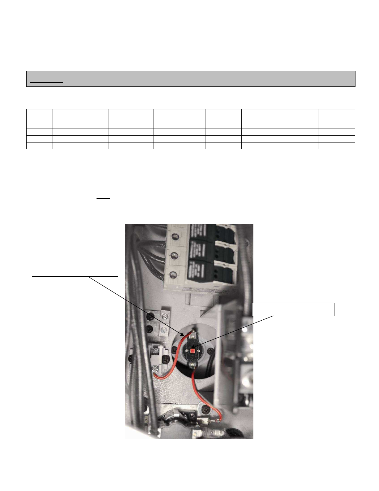
ELECTRIC UNIT). For security reasons, the electrical element has a manual reset thermostatic sensor that is located
inside the electrical unit. If the temperature of the electric unit exceeds the high limit, the thermostatic sensor will
disengage the elements. After finding and fixing the problem that has caused the unit to overheat (static pressure too
high, fan breakdown, etc.), reactivate by pressing the red “manual reset” button on the thermostatic sensor (L-170
thermodisc).
TEMP. VAR.
(O F)
BTU/HR
AMPS
TOTAL
INSIDE VIEW OF ELECTRIC ELEMENT
BREAKER
REQUIRED
FEEDER
GAUGE
VOLTAGE
SINGLE PHASE
ELEMENTS
QTY
L-170 Thermodisc RESET
Red button manual reset
29
Page 30

10. THERMOSTAT INSTALLATION
10.1. WOOD FURNACE ONLY
The furnace must be connected to a thermostat. You can use the one provided with the unit or use one that is already
installed in your home. The thermostat must be installed on an inside wall and located where it is not likely to be
affected by the draft coming from an air outlet. It must be installed at a minimum of 55 inches (140cm) above the floor.
It is recommended to connect the thermostat to the furnace with a seven or eight threads wire connecting terminals
Rc, Rh (connect only one of the two terminal R if there is a jumper between Rc and Rh in the thermostat), C, W, Y, G,
O and B. If the thermostat is using a dry contact (powered by batteries), it is not necessary to connect the C (common)
terminal to the thermostat. Refer to the electrical diagram.
Once wired to the furnace, it is possible to verify the signals coming from the wall thermostat. Simply go on the touch
screen main menu, under the “TROUBLESHOOT LINK’’ menu and going to page 1 as shown below. When a signal is
sent from the thermostat, the circle corresponding to the signal should appear green.
10.1.1. COMBINATION WOOD-ELECTRIC OR WOOD-OIL FURNACE
Only one thermostat is necessary to control the wood furnace and any other auxiliary heating source. Installing the
thermostat is done the same way as if the furnace was wood only. See Section 11.4.1 - TRANSITION TO AN
AUXILIARY HEAT SOURCE to learn how to make it work.
10.1.2. COMBINATION WOOD-ELECTRIC-OIL
Only one thermostat is necessary to control the wood furnace and any other auxiliary heating source. Installing the
thermostat is done the same way as if the furnace was wood only. See Section 11.4.1 - TRANSITION TO AN
AUXILIARY HEAT SOURCE to learn how to make it work.
30
Page 31
10.2. INSTALLATION OF AN AIR CONDITIONING UNIT
The Max Caddy furnace has been tested with an optional air conditioning unit. If this option is chosen, we recommend
an installation as per the graphic provided below.
Damper
A/C coil
Damper
This installation will provide the most efficient and safe operation of the air conditioning unit using the distribution
blower of the Max Caddy furnace during summer. In order to complete the installation of an air conditioning unit, the
main thermostat must be a “heat/cool” type. Furthermore, the desired distribution blower speed must be programmed
on the touch screen in the blower speed menu. (See Section 11.5 DISTRIBUTION BLOWER SPEED
CONFIGURATION
It must be noted that upon thermostatic demand for cooling, the distribution blower will start immediately at the
programmed speed. For the air conditioning damper wiring see Section 28 - LINK BOARD OPTIONS
CONNECTIONS.
The capacity and characteristics of the air conditioning unit that has been tested with the MAX Caddy are stated below.
The use of another brand with similar capacity and characteristics is adequate.
Condenser brand: Goodman GSX13048
Capacity: 4 ton
Coil type: Type A, CAUF uncased indoor coil.
10.3. HEATPUMP INSTALLATION
It is possible to pair a heat pump to the Max Caddy. To determine the priority of operation of these two modes of
heating, you must go to Section 11.4.3 - AUXILIARY HEAT SOURCE PRIORITIZATION.
For connection of the heat pump to your furnace, see Section 28.7 - HEAT PUMP
Note: If a heat pump is connected to the Max Caddy, the electrical element must be installed to ensure an auxiliary
heat source. (PA08535 (20kW), PA08545 (25kW)
For installation of air conditioning coil, refer to Section 10.2 - INSTALLATION OF AN AIR CONDITIONING UNIT.
31
Page 32

10.4. INSTALLATION OF A DOMESTIC WATER PRE-HEATING SYSTEM OR A HUMIDIFIER
A water heating loop option is also available to pre-heat domestic water using the energy produced by the Max Caddy
wood furnace. This water loop kit will be inserted between the wood combustion chamber and the heat exchangers.
When heating with wood, the heat from the furnace will pre-heat domestic water that will be stored in a feed tank
before entering your existing water heater. Removable panels are installed on both sides of the furnace for quick and
easy installation of the loop. A 24 volt solenoid valve must be installed at the inlet of the loop and must be connected to
the HOT H20 terminal on the PC board; when the plenum temperature reaches 120°F, the valve opens to allow water
circulation. It closes when the temperature drops below 100°F to prevent overcooling the combustion chamber during
low firing rates. See section 28.3 -
HOT WATER
for electrical connection. Complete installation and operation
instructions for the hot water loop kit are supplied with the kit.
NOTE : NEVER INSTALL AN AUTOMATIC FEEDER.
The HUM OUT terminal may also be used to activate the 24 volt relay of a humidifier installed in the system which,
when connected to the PC Board, will be activated and deactivated at the same temperatures as the water solenoid
valve (120°F et 100°F). See section 28.6 - HUMIDIFIER for electrical connections.
To verify the status (open or closed) of the valve/relay, see section 14.1 - VALIDATING STATUS OF A COMPONENT.
11. CONFIGURATION AND OPERATING INSTRUCTIONS
11.1. CONTROLS SYSTEM
The Max Caddy has a sophisticated electronic control. This system is more versatile. All connections are made from
the control panel. Terminal blocks are provided for all components and options.
Before you configure your system and learn how to operate it, make sure that your wall thermostat is wired correctly to
your furnace, that the temperature probe (RTD) is well installed in the hot air plenum and connected to the link board
and that your air distribution system is complete.
The furnace uses a touch screen, the latest technology in control devices. Blowers, power supplies and options are
controlled from this screen.
It is important to note that your furnace is equipped with three main electronic components: the link board, the power
board and the touch screen. The power board is already installed in the blower box.
The power board is used to supply current to the different electrical components, in particular:
- Supply current to the different electronic boards;
- Supply current to the distribution fan;
- Supply current to the sequencers of the electrical unit (optional);
- Supply current to the oil burner.
The link board is used more precisely for:
- Connecting the hot air plenum’s temperature probe (RTD type);
- Connecting the wall thermostat;
- Connecting complementary equipments;
- Connecting a heat pump.
The LCD touch screen is used to operate the system. More precisely for:
- Choosing the combustion parameters;
- Selecting the options used;
- Show the temperature in the hot air plenum;
- Selecting heating priority;
- Selecting language and units displayed;
- Viewing statistics;
- Selecting distribution fan speeds;
- Troubleshooting to detect problems with the appliance.
32
Page 33
11.2. SYSTEM CONFIGURATION
Once the installation is complete and before using the unit, the furnace should be configured to activate all applicable
functions depending on options chosen. To do this, it is important to know which options are installed on your furnace.
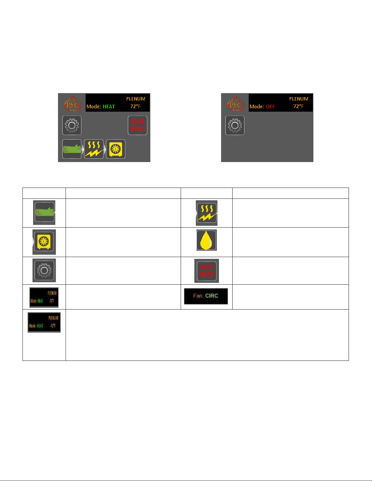
11.3. TOUCH SCREEN
The LCD control is an electronic visual display as well as a touch screen that will light-up as you touch any location on
the display area. The main status page will then display different icons layout depending if the furnace is on or not.
Main menu – Furnace « ON »
Main menu – Furnace « OFF »
11.3.1. ICONS DESCRIPTION
Icons Description Icons Description
Wood heating
Green : Heating mode
Yellow : Auxiliary heating mode
Heat pump
Green : Unit on
Yellow : On hold
Settings
Temperature in the hot air plenum
Possible states of the furnace:
HEAT: When the word HEAT is green, the furnace is in heating mode. If the furnace is waiting for a
demand for heating, the word HEAT is written in yellow.
COOL: When the word COOL is green, the furnace is in cooling mode. If the furnace is waiting for a
demand for cooling, the word COOL will be written in yellow.
OFF: The furnace is stopped.
Electrical Element
Green : Unit on
Yellow : On hold
Oil unit
Green : Unit on
Yellow : On hold
Displayed when an auxiliary heat source
has been selected.
Distribution blower is in circulation
mode. (CIRC)
33
Page 34

11.3.2. LANGUAGE SELECTION AND TEMPERATURE UNIT
To choose the language and temperature unit, press the "Settings" button. In the "Main" menu, choose "SETUP" and
then "GENERAL". Choose the preferred language and temperature unit.
11.4. ADDING AUXILIARY HEATING SOURCE AND SELECTION OF OPTIONS
To add an auxiliary source of heating or to add options to your furnace, press the "Settings" button. On the “MAIN”
page, choose “SETUP” and “OPTIONS”.
By default, no auxiliary source of heating or options are selected. To select an option, simply press the white square to
the left of the desired option. When an option is chosen, the selected square turns green.
To confirm the selection of your options, press the button '' SAVE + EXIT ''. This step takes you to a list of questions
about your selections that are essential for their good functioning.
11.4.1. TRANSITION TO AN AUXILIARY HEAT SOURCE
When there is a demand for heat, the furnace checks the temperature in the plenum. If the temperature is beyond the
KIP, the fan will turn on. If the temperature is below the KIP, the furnace will wait the "Rise Time" delay and check the
temperature again in the plenum. If the temperature in the plenum goes up 20°F but has not reached the KIP, the
furnace will wait for additional time ("KIP Time") and recheck the temperature in the plenum. If the temperature has not
reached the KIP, the auxiliary heating will start. The icon "Wood" will turn yellow and the auxiliary heat icon will turn
green.
For the electrical element and/or the oil unit, the fan starts as soon as the thermostat asks for heat. In other words, for
safety reasons, the fan does not wait for the hot air plenum to reach a predetermined minimum temperature.
The furnace remembers what heating source was used in the last request of the thermostat. If the last heating demand
was met by the auxiliary heater, the furnace automatically start this one.
To restart the furnace using the wood mode, go on the touch screen on the main page and press on the wood icon.
The icon will become green and the auxiliary heating source icon will become yellow.
11.4.2. TRANSITION SETTINGS
It is possible to slightly adjust the transition settings from the wood option to the auxiliary source of heating. To do this,
go to the "MAIN" page on the touch screen under the "SETUP" option and choose "WOOD SETUP ". On this page,
you can change the KIP, KOP, the Rise Time and KIP Time.
KIP (Kick-In point): Temperature of the plenum where the fan turns on.
KOP (Kick-Out point): Temperature of the plenum when the fan stops.
Rise Time: Time allowed for plenum temperature to increase by 20 ° F.
KIP Time: Additional time allowed to reach the KIP when the Rise Time ended with an increase of 20°F.
34
Page 35
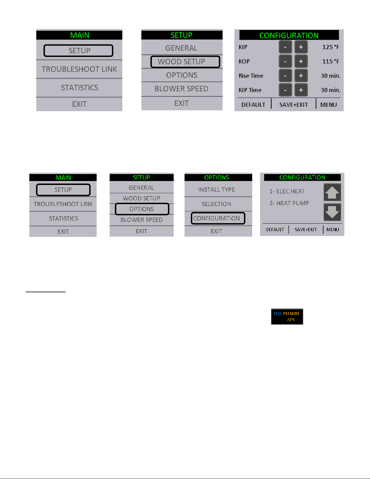
11.4.3. AUXILIARY HEAT SOURCE PRIORITIZATION
If you have configured one or many auxiliary heating sources (electrical element, heat pump, oil), you must choose the
priority order when there is a heating demand. If, for example, the wood no longer provides sufficient heat, the auxiliary
heating selected in priority one will take over. If priority one no longer provides enough heat, or does not provide it fast
enough, priority 2 will take over. Heating priorities are chosen in the "MAIN" menu, under the "SETUP" option. Select
"OPTIONS" and "CONFIGURATION". Use the arrows to select the priority order.
11.4.4. EXTERNAL TEMPERATURE PROBE
It is possible to connect an external temperature probe on the Max Caddy. This temperature probe is used primarily to
reduce electricity consumption and reduce the bill by prioritizing the transition to an auxiliary heating source when it is
too cold outside or when it is the overcharging billing period (peak usage) depending on the electricity supplier.
HEAT PUMP : With a combination wood, electrical component and heat pump you can set your temperature probe to
not use your heat pump when it is too cold and the coefficient of performance becomes too low. (Electrical element
should be prioritize during configuration the outdoor temperature probe.)
When the temperature probe is functioning, the « ECO » mode will show on the main page.
11.4.4.1. “BI-ENERGY” FUNCTION
The bi-energy function is used when a local utility company (Hydro-Quebec for instance) offers a bi-energy program
under which a preferential rate is given, provided that the appliance is equipped with an electronic control that
guaranties the use of a particular source of energy (ex: electricity) based on a given criterion (ex: the outdoor
temperature).
When the MAX Caddy is programmed for bi-energy, the temperature probe (normally open contact) is connected to the
PC board (See Section 28.2 temperature is above a certain value (this reference value is programmed into the system provided by the utility
company). As long as the contact remains open, the electrical unit supplies the heat when the wood is not able to
satisfy the thermostatic demand. If, however, the outside temperature reaches a level below the reference value, the
contact closes and the oil unit is used as the option for heat if the wood is not able to satisfy the thermostatic demand.
OUTDOOR PROBE
). The contact remains open for as long as the outside
35
Page 36
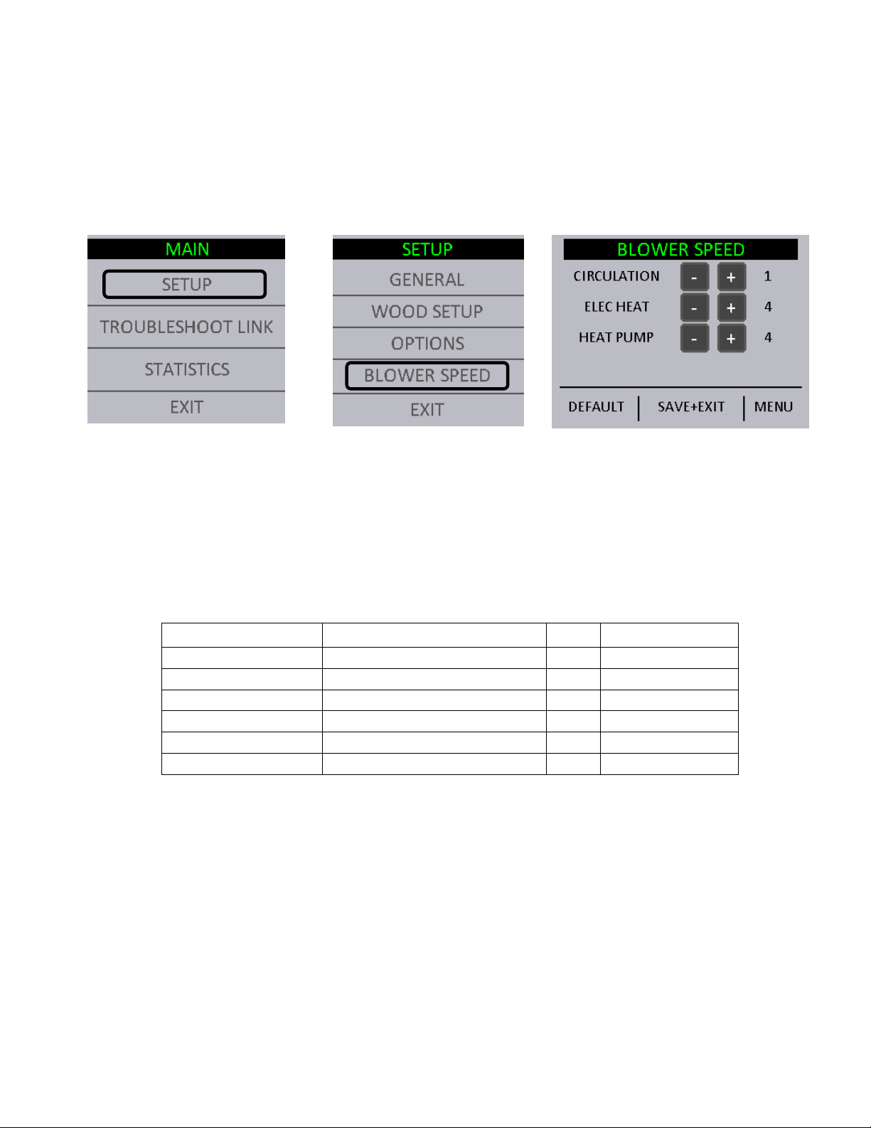
11.5. DISTRIBUTION BLOWER SPEED CONFIGURATION
Functional
Speed
Corresponding data
CFM*
Static pressure
It is possible to adjust the speed of the distribution blower for circulation mode, air conditioning and any other mode of
auxiliary heaters.
NOTE: When heating with wood, the fan distribution speeds are programmed in order to provide the best thermal
exchange and cannot be changed.
It is possible to adjust the blower speed in “CIRCULATION” mode at any time by going in the main menu under
“CONFIGURATION” and “BLOWER SPEED”.
The blower speed adjustments for auxiliary heating are available only if the option was activated. The selected speed
in this menu will be the speeds used in the "CIRC", "COOL" and "HEAT" mode.
The adjustment of all controls must be done by a qualified technician. The controls settings and the blower speed must
conform to the recommendations of the CMMTQ.
11.5.1. DISTRIBUTION FAN SPEEDS
Your furnace is equipped with a 4-speed blower. Using the central processing unit, we have created 6 functional
speeds. Refer to the following table for the various speed configurations.
1 Blower speed #1 using 98V 600 0.2" H2O
2 Blower speed #1 using 115V 760 0.2" H2O
3 Blower speed #2 using 98V 840 0.2" H2O
4 Blower speed #2 using 115V 950 0.2" H2O
5 Blower speed #3 using 115V 1150 0.2" H2O
6 Blower speed #4 using 115V 1260 0.2" H2O
*These results were measured at exit of plenum during laboratory tests. Results may vary depending of the
configuration and installation.
11.6. SYSTEM BALANCING
It is important to call upon a professional installer for the installation of the furnace and the ducting system
configuration. Certain check-ups must be performed and certain rules must be respected in order not to damage the
blower.
When all components are installed on the furnace and the ducting system is connected to the various rooms of the
house, you must balance the ducting system. In order to do so, start the distribution blower by going in the
‘’TROUBLESHOOT LINK’’ menu on Page 5 and select speed #4.
36
Page 37

It is important to respect the velocity in the main duct, the secondary ducts, as well as the velocity at the room outlets.
The static pressure of your system must be adjusted to at least 0.2 IN.W.C. and must not exceed 0.5 IN.W.C. Finally,
make sure that you never exceed the maximum blower current.
11.7. OPERATING INSTRUCTIONS
11.7.1. HEAT Mode
When the temperature in your house is below the value at which your wall thermostat is programmed, a signal is sent
to your furnace through the PC board, activating the motorized damper located in front of the furnace and thus allowing
more oxygen to the fire. The RTD temperature probe, located inside the hot air plenum of your furnace, reads the
plenum temperature continuously. When the temperature reaches the start-up value selected by the user (KIP – Kick-
in Point), the distribution blower starts functioning at the minimum speed. Thereafter, the blower increments its speed
until it reaches the best efficiency point (BEP) determined by the manufacturer. If the temperature inside the hot air
plenum exceeds the limit determined by the manufacturer, the blower automatically selects the maximal speed and the
motorized damper closes in order to slow down combustion. When the temperature returns to a safe level, the blower
speed gradually returns to the speed required to maintain the BEP.
11.7.2. COOL Mode
If an air conditioning unit is installed, the PC board will have to be connected to a dual-function wall thermostat (e.g.
“heat/cool”) in order to synchronize the start of the furnace blower with the start of the air conditioning condenser.
Upon receiving the wall thermostat’s signal, the furnace blower will start functioning at the speed selected by the user.
11.7.3. CIRC Mode (air circulation)
This mode is used to circulate air during summer. Thus you will benefit from your ducting system to circulate fresh air
from your basement throughout the house. To activate the circulation mode, put the thermostat in FAN-ON mode.
37
Page 38

11.8. WOOD HEATING
ALWAYS KEEP THE DOOR AND THE ASH DRAWER CLOSED
PROCEDURE TO OPEN THE LOADING DOOR
11.8.1. LIGHTING
1. Open the furnace door
Note: If there is already a bed of coals in the firebox, go to pre-heating.
2. Place one or two dry kindlings at the front of the furnace.
3. Place newspaper strips on top of the kindlings.
4. Cover the newspaper with more kindlings and small pieces of dry wood.
5. Add newspaper strips, then light the fire a low as possible and leave the door 1/2" (13 mm) opened. If you fail
lighting the fire, you might experience a back draft through the air inlets.
11.8.2. PREHEATING
1. Once the kindling is well ignited or the coals revived, put 2 or 3 fire logs in such a way that the flames can interlace
between the logs. Then, close the door. It is important to respect these loading sequences so that the wood will
burn from the front to the back of the furnace.
2. Wait 15 to 20 minutes, then proceed with loading the furnace.
11.8.3. HEATING
1. When loading the furnace, lower the kindled pieces of wood and place them at the center of the combustion
chamber before adding new logs.
2. Do not overload. Air must circulate freely in the upper part of the combustion chamber in order to obtain an efficient
operation of the appliance (secondary burn). Please note that a small hot fire will produce much less residues than
a large, smouldering one.
IMPORTANT: DURING THE HEATING PROCESS, REMOVE THE ASHES AND WOOD THAT COULD
OBSTRUCT THE 1/4" (6.4 mm) HOLE (PILOT) LOCATED BELOW THE DOOR, INSIDE THE FURNACE’S
COMBUSTION CHAMBER.
TO MINIMIZE THE RISK OF SMOKE SPILLAGE, OPEN THE DOOR 1”
AND WAIT ABOUT 10 SECONDS BEFORE OPENING IT COMPLETELY.
THE PURPOSE IS TO STABILIZE THE PRESSURE INSIDE THE FURNACE.
11.8.4. EARLY SIGNS OF AN OVERFIRED FURNACE:
• Roaring fire.
• Chimney connector is glowing red.
• Extreme heat coming from the furnace. If this occurs, DO NOT OPEN THE DOOR. Shut-off the air inlet opening
completely, and wait until the glow has completely subsided.
(except for lighting and maintenance).
38
Page 39

11.8.5. WOOD AS HEATING FUEL
ATTENTION
NE JAMAIS FAIRE BRÛLER DE DÉCHETS, DE LA GAZOLINE, DU NAPHTA, DE L’HUILE À MOTEUR
OU TOUT AUTRE PRODUIT SEMBLABLE.
We recommend that you burn dry hard wood only.
There are two important factors to be considered when choosing a type of wood: the moisture content and the wood
density. Hardwood, oak and beech for example, will provide better results because of the high density and minimal tar
produced during combustion. It is highly recommended to use wood that has been dried for at least six months.
DO NOT USE COAL AS HEATING FUEL IN THIS APPLIANCE.
Whenever a high rate of smoke is noticed in the room, you must:
1. Open doors and windows.
2. Make sure the furnace door is closed as well as the damper (if necessary, lower the thermostat starting point or
unhook the damper chain and close the barometric draft control manually).
3. When the furnace has cooled down, inspect the chimney to detect obstructions and consult a specialist to
determine the cause of the smoke spillage.
11.8.6. PROLONGED POWER FAILURE
In case of prolonged power failure (over 10 minutes), to reduce the risk of overheating, it is recommended to heat
moderately and to open the furnace filter compartment in order to facilitate air circulation by natural gravity around the
firebox of the Max Caddy wood furnace.
11.8.7. CHIMNEY FIRES
This might occur when the fire gets extremely hot. Burning cardboard, branches, or small pieces of wood can ignite
the creosote residue accumulated in the evacuation flue system. The usual signs are:
1. Rumbling.
2. The flue gets extremely hot (red).
3. Flames or sparks are coming out of the chimney.
4. In case of a chimney fire, call your local fire department immediately and sprinkle the roof around the chimney with
water.
Make sure that the furnace door is closed as well as the damper (if necessary, lower the thermostat starting point or
release the chain from the damper and close the barometric draft control manually).
If the fire gets uncontrollable due to an improper use or because the draft is too strong, follow the same procedure as
in a chimney fire except that you will have to OPEN the barometric draft control manually.
11.8.8. LOCAL FIRE DEPARTMENT
Phone number: ___________________________________
39
Page 40

12. MAINTENANCE
Heat exchangers
12.1. MAINTENANCE OF THE EXCHANGERS
Heat exchangers must be cleaned thoroughly at the end of every heating season. During summer, the air in
basements is damper and with minimal air circulation within the furnace, it can mix with creosote and/or sooth deposits
in the exchangers to form an acid that could accelerate the corrosion process and induce premature decay of the steel.
Corrosion damages are not covered under warranty.
Smoke pipe and exchangers must be inspected regularly during the heating season. Access to the exchangers is easy
and does not require tools; just remove the decorative facing by just lifting it, remove the wing nut that keeps the
hinged access panel closed. (See pictures below)
Wing nut
cover
Heat exchangers
Before cleaning the three exchanger pipes, move the upper vermiculite baffle board of the combustion chamber forward
(see drawing on next page). Using the scraper, clean the three exchanger pipes. The accumulated dirt in the lateral
exchangers will fall into the combustion chamber; the dirt in the central exchanger will have to be removed from the front
or the back of the furnace. Then, ensure that the upper baffle board is free of ashes. Do not forget to push the upper
baffle board back to its original position. Finally, close the exchanger access door.
Max Caddy section view
40
Page 41

Locking pin
12.2. CHIMNEY MAINTENANCE
The most efficient way to sweep a chimney is to run a hard chimney sweeping brush. Brush from the top down so
sooth and creosote deposits will detach from the chimney liner and fall down to the bottom of the chimney where it can
be easily removed.
The chimney must be inspected regularly and any creosote build-up must be removed without delay. Monthly cleaning
should be sufficient during cold winter months while more frequent cleaning could be required during milder periods.
12.3. SMOKE PIPE INSPECTION
• The smoke pipe must be inspected regularly during the heating season.
• The pipe must be examined carefully to detect any defect or damage.
• The pipe can be reassembled if no defect is detected and defective pipe must be replaced immediately.
• Burn wood only in this furnace.
• As a combustible, well seasoned hardwood in 18" to 22" logs works best
• Regularly, examine the flue pipes, the joints, and the sealing trims to ensure that the smoke and the combustion
gases are not transported into the air ducting system.
12.4. BLOWER MOTOR MAINTENANCE
Periodic cleaning of the fan housing as well as fan and fan blades using a vacuum cleaner is necessary in order not to
affect performance and cause overheating of the latter.
DO NOT OVERLUBRICATE.
12.5. FILTERS
Never use the furnace without air filters. To function as expected, controlled combustion wood burning appliance must
be maintained on a regular basis. This means that the chimney, the gaskets and the pipes must be kept in good
working order and the air filter cleaned or replaced regularly. Use the same size and type of filter as the original. High
efficiency 2-ply, 3-ply, or 4-ply filters are recommended.
12.5.1. AIR FILTER DIMENSIONS
Max Caddy: 16" x 20" x 1" filter
12.6. DOOR GASKET MAINTENANCE
It is important to maintain the door gasket in good condition. After a while, the gasket might sag; a door adjustment
may then be required. If the door adjustment is not sufficient, replace the door gasket with a genuine one.
12.6.1. DOOR ADJUSTMENT PROCEDURE
1. Unscrew completely the locking pin (see picture below).
41
Page 42

2. To increase the pressure of the door on the gasket, turn the handle counter clockwise; to decrease the pressure of
the door on the gasket, turn the handle clockwise until desired pressure is attained.
3. Then, screw back the locking pin about 1/4" deep and make sure you lock it in place with the nut.
13. REPLACEMENT PARTS
Your PSG furnace is designed to burn clean and requires little maintenance. It is recommended to conduct a visual
inspection at least once a month to uncover any damage to the unit. Any defect must be repaired without delay using
genuine PSG replacement parts. You can find a complete list of replacement parts in section 29 - EXPLODED VIEW
AND PART LIST or on our website at www.caddyfurnaces.com.
13.1. DOOR GLASS
• Inspect the glass regularly to detect any glass failure. If you find any defect, stop using the wood furnace
immediately. Never operate a wood furnace with a broken glass.
• If you have to change your door glass, you must use Pyroceram 3/16" (5mm) thick. Use genuine parts sold by
a PSG authorized dealer.
• To replace the glass, remove the screws that hold the glass retainers in place. Removed these retainers and
replace the defective glass; the glass gasket should be replace at the same time. To put back in place,
reverse the procedure.
• Do not use abrasive cleanser. Special cleansers for wood fireplaces glass are available in any good hardware
store or specialty hearth retailer.
• Clean glass ONLY when the unit has cooled down.
13.2. GASKET
We recommend replacing the gasket that seals the door once a year, in order to maintain a good control of the
combustion for maximum efficiency and security. To replace your door gasket, remove the old gasket and adhesive.
Clean the surface thoroughly, apply a high-temp adhesive/silicone (650 oF) sold for that particular use, and put the new
gasket onto the door. Wait for at least 4 hours before lighting your furnace.
14. TROUBLESHOOTING
When you have issues with your furnace, your first reaction may be to call technical support. This section will help you
save time and money by enabling you to solve simple problems by yourself. Most common problems are generally
caused by the following five factors:
1. Wrong operation or lack of maintenance;
2. Bad installation;
3. Poor quality combustible;
4. Component failure;
5. Factory defect.
The furnace is equipped with a pc board that allows the furnace to diagnose itself. It is thus important not to unplug the
furnace if there is an issue with it. First, because unplugging the furnace will disable all the security features of the
furnace, and second, because you will not be able to see the error code given by the furnace to understand what is the
problem. It is thus important to read carefully this section before calling technical support.
The following sections will help you test each component individually and will also give you many tips in how to solve
any problems related to a specific error code.
NOTE: IF YOU NEED TO CONTACT YOUR DEALER OR TECHNICAL SUPPORT, MAKE SURE TO HAVE THE
MODEL OF YOUR APPLIANCE AND THE SERIAL NUMBER ON HAND. (THEY CAN BE FOUND ON THE
CERTIFICATION LABEL ON THE SIDE OF THE FURNACE).
WARNING: RISK OF ELECTRIC SHOCK. IF YOU NEED TO MANUALY TEST, HANDLE OR REPLACE A
COMPONENT, THE FURNACE MUST BE DISCONNECTED FROM ITS POWER SUPPLY.
42
Page 43
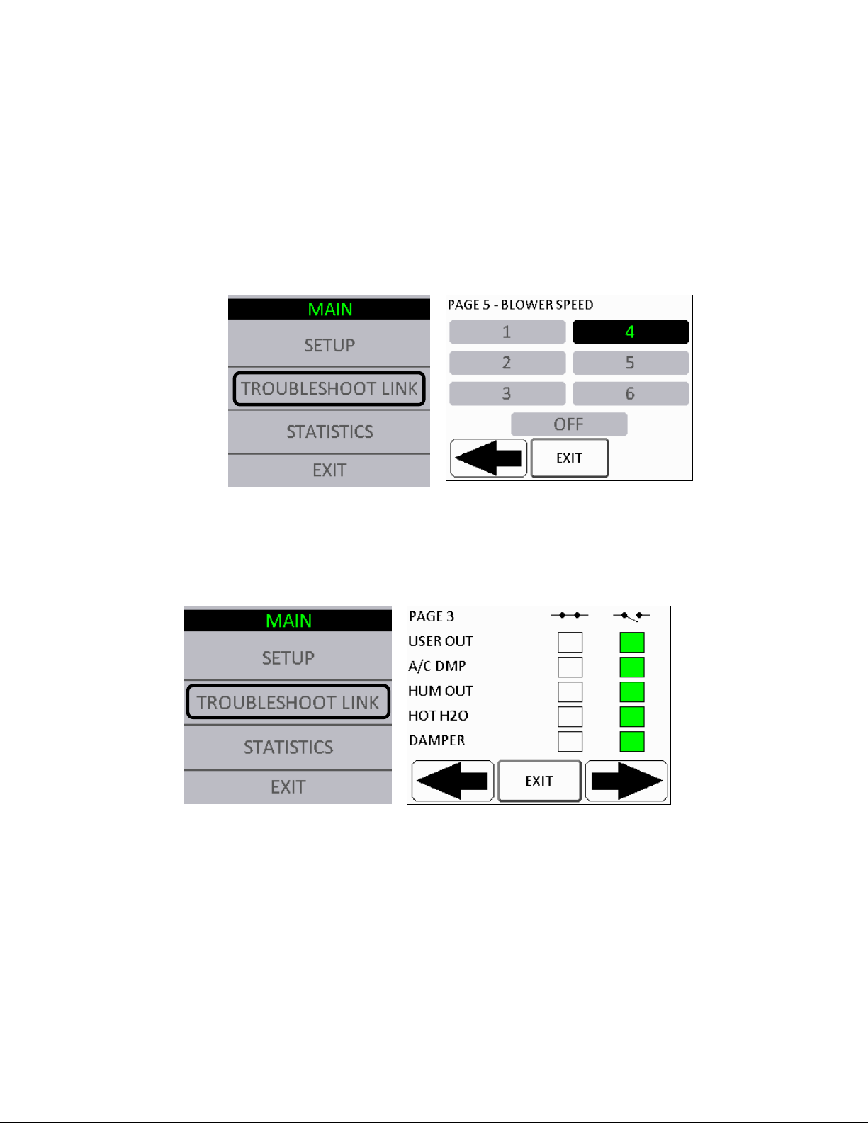
14.1. VALIDATING STATUS OF A COMPONENT
When using your furnace, you can validate at any time, the status of any of the following components:
• Distribution blower
• Air damper
• Temperature probe (RTD)
• Hot water system
• Humidifier
• Heat pump
14.1.1. DISTRIBUTION BLOWER
To check the status of the distribution blower, go to the main menu under “TROUBLESHOOT LINK" then go to page 5.
When the fan is on, the selected speed is black.
14.1.2. AIR DAMPER, HOT WATER AND HUMIDIFIER
To check the status of the air damper, hot water or humidifier, go to the main menu under "TROUBLESHOOT LINK"
then go to page 3. When the furnace is in wood heating, the damper is open. The green square next to “DAMPER”
should be on the left, (closed circuit). When another heating mode is on, the damper is closed, so the circuit is open
and the green square is on the right. Same logic goes for the hot water and the humidifier.
43
Page 44

14.1.3. TEMPERATURE PROBE (RTD)
The temperature probe continuously reads the temperature in the plenum and displays it on the main page in the upper
right corner. If the probe fails, the error message "PLENUM OVERTEMP" will appear. See section 14.2 - MAIN
ERROR CODES, POSSIBLE CAUSES AND SOLUTIONS for more information.
14.2. MAIN ERROR CODES, POSSIBLE CAUSES AND SOLUTIONS
This section contains main error codes, possible causes and many suggestions to guide you in resolving them. To go
RESET
back to the main menu, press the
button.
NOTE: IF, AFTER PERFORMING ALL THE POSSIBLE SOLUTIONS MENTIONED IN THE FOLLOWING SECTION,
YOU ARE STILL EXPERIENCING PROBLEMS WITH YOUR FURNACE, CALL YOUR LOCAL DEALER OR
AFTER-SALE SERVICE.
NOTE: IF YOU NEED TO CONTACT YOUR DEALER OR TECHNICAL SUPPORT, MAKE SURE TO HAVE THE
MODEL OF YOUR FURNACE AND THE SERIAL NUMBER ON HAND. (THEY CAN BE FOUND ON THE
CERTIFICATION LABEL ON THE SIDE OF THE FURNACE).
14.2.1. UNIT OVERHEAT
44
Page 45

The temperature probe (RTD) is disconnected or defective: If the displayed plenum temperature on the touch screen is
0 F or 1140 F, the temperature probe is either disconnected or defective. Check the probe connection (see Section 9.4
- HOT AIR PLENUM TEMPERATURE PROBE INSTALLATION AND CONNECTION (RTD) or replace if necessary.
The air filter is dirty or clogged: Clean the furnace filter. If the filter is damaged, replace it.
The distribution fan is faulty: Check the fan status. To do this, see Section 14.1.1 - DISTRIBUTION BLOWER. Replace
it if necessary.
The fuse of the distribution fan is blown: Change the 12A fuse on the power board.
The pressure in the plenum is too high: Make sure your air distribution system is well balanced and that the filter is not
dirty or clogged. Ensure that returns / side vents are not blocked.
14.2.2. NO HEAT
This message appears:
• When the wood furnace failed to raise the temperature in the plenum enough to reach the KIP or
• When the temperature does not reach 100 F in the plenum in less than five minutes for auxiliary heat.
Make sure there is a fire in the furnace or the auxiliary heating sources are functional and well connected.
14.2.3. COMMUNICATION ERROR
Communication error: The information from the touch screen cannot be read by the link board. It is possible that the
telecommunication wire is not plugged in. Make sure each end of the wire makes good contact in the connector. It is
also possible that the wire is damaged. In this case, replace it.
45
Page 46

14.2.4. SMOKE SMELL
• Venting system leaks. Inspect all vent connections. All vent connector joints must be sealed and fastened in
accordance with the vent manufacturer's instructions to ensure consistent performance and avoid smoke and ash
spillage.
• Worn gaskets. Gaskets may be allowing smoke spillage (doors, clean out traps, etc). Make sure that all gaskets
are in good condition and replace them with original parts if necessary. Make sure the door is well adjusted.
• Negative pressure. A faint wood-burning odor during ignition or shut down is normal. Although, if this increases
beyond what is considered normal or if you notice an unusual soot build-up on walls or furniture, check your
venting system carefully for leaks and make sure all gaskets are in good condition. The furnace blower produces a
negative pressure in the room. It draws air from the inside of the room, through the furnace and then outdoors. In
the same manner, other appliances can also create a larger negative pressure. In this case, as the air naturally
flows from a high pressure point to a low pressure point, a larger negative pressure can draw smoke from the
inside of the furnace into the room. The furnace can also be affected by other mechanical ventilation systems,
causing the same effect as mentioned previously. Using a fresh air intake will prevent negative pressure. Also,
make sure the recommended maintenance schedule has been followed.
14.2.5. THE LCD TOUCH SCREEN DOES NOT LIGHTUP.
• There is no electrical current going to the furnace. Check if the furnace is connected and if there is current in
the wall outlet. Check if the fuse is blown. Replace it if necessary.
• TELCO wire is defective or not connected properly.
• The temperature of the screen is below zero. When the screen is exposed to temperatures too cold, the liquid
crystals may not function properly which causes a loss of communication. This situation may occur in cases where
the unit has arrived from outside by a carrier or is subjected to a room temperature too low as in an unheated
cottage or a very cold garage.
14.2.6. AUXILIARY OVERRIDE
This message appears when a heat signal from the existing furnace’s thermostat is sent and the Max Caddy shuts
itself down.
46
Page 47

15. GENERAL ELECTRICAL DIAGRAM
47
Page 48
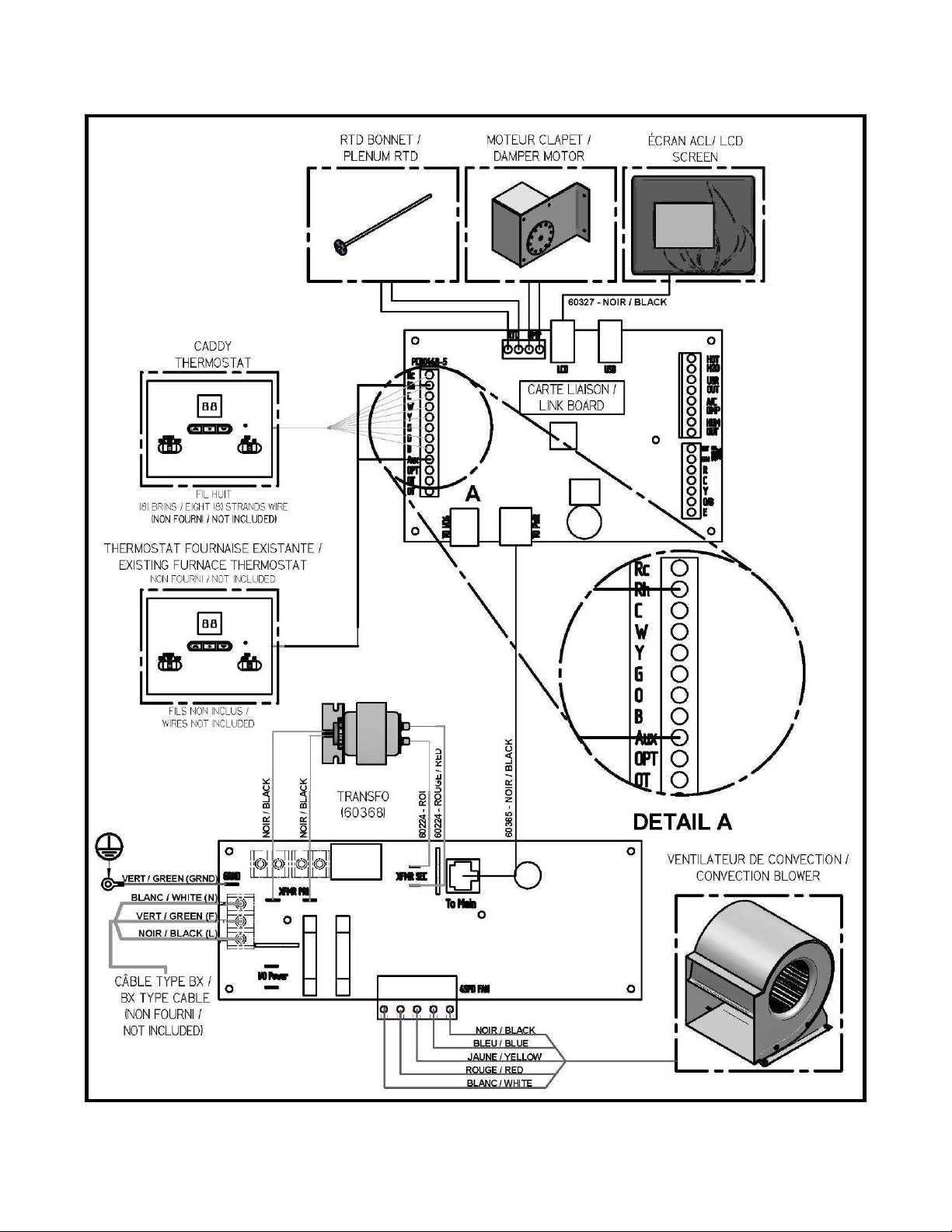
16. ELECTRICAL DIAGRAM FOR PARALLEL FURNACE
48
Page 49
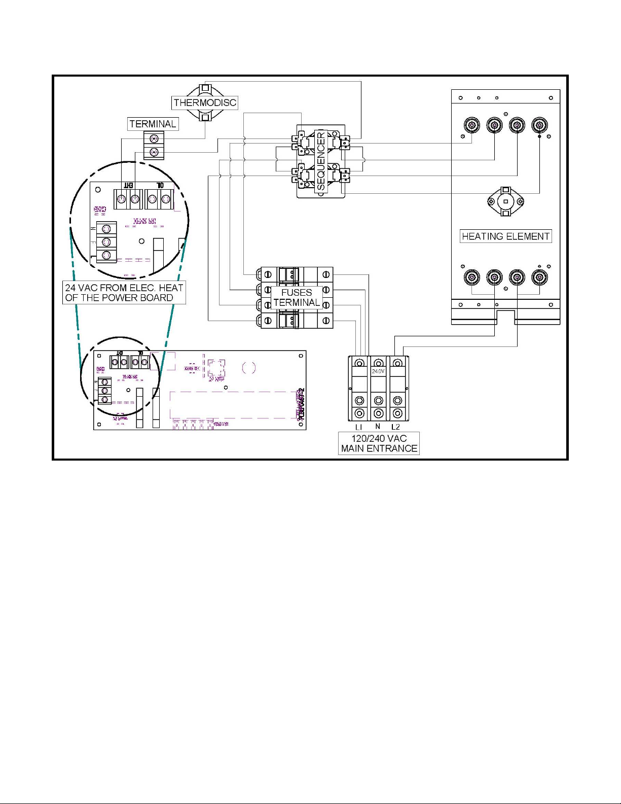
17. ELECTRICAL DIAGRAM FOR ELECTRIC UNIT
49
Page 50

INSTALLATION AND OPERATION
INSTRUCTIONS FOR
WOOD/OIL
COMBINATION FURNACE
NECESSARY COMPONENTS FOR MAX CADDY WOOD/OIL COMBINATION FURNACE
To use the configuration of the Max Caddy wood/oil furnace you have to assemble the blower assembly (PA08566),
sold separately. The assembly instructions are in the instruction manual supplied with the blower assembly kit.
You must also assemble the oil assembly kit. The assembly instructions are in the instruction manual supplied with the
oil assembly kit (PA08512 or PA08513) sold separately.
50
Page 51

GENERAL INFORMATION FOR OIL FURNACE
READ THIS MANUAL THOROUGHLY BEFORE OPERATING THE FURNACE
CAUTION CAUTION
EXPLOSION OR FIRE HAZARD. FOR YOUR
SAFETY: DO NOT STORE OR USE
GASOLINE OR ANY FLAMMABLE LIQUIDS
OR VAPORS IN THE VICINITY OF THIS
HEATING UNIT.
DO NOT ATTEMPT TO LIGHT THE BURNER
WHEN EXCESS OIL HAS ACCUMULATED,
WHEN THE APPLIANCE IS FULL OF
VAPOR, OR WHEN THE COMBUSTION
CHAMBER IS VERY HOT.
DO NOT BURN WASTE OR PAPER IN THE APPLIANCE.
DO NOT LEAVE PAPER OR ANY COMBUSTIBLE MATERIAL
AROUND THE APPLIANCE.
WARNING: INSTALL THE NOZZLE. ADJUST THE ELECTRODES.
ADJUST PRESSION.
NOTE: IF A PROBLEM RESULTS FROM IMPROPER INSTALLATION,
NO PRODUCT WARRANTY WILL BE VALID.
DO NOT TRY TO MODIFY THE UNIT OR ITS COMMANDS
– CALL A TECHNICIAN.
PLEASE SAVE THIS DOCUMENT!
51
Page 52

18. GENERAL NOTES
This instructions manual treats mainly of the oil burning unit of your wood/oil combination furnace.
To obtain the maximum efficiency out of your furnace, follow the advice below regarding the installation and operation
of your WOOD/OIL combination furnace.
• Respect the local codes (when in doubt, consult your local dealer).
• Respect the clearances indicated on this instructions manual and make sure that they match those indicated
on the appliance’s certification label;
• Make sure that your furnace is installed in conformity with the instructions on the certification label;
• All the controls adjustments must be performed by a qualified technician.
WARNING
THE INSTALLATION OF THE WOOD/OIL COMBINATION FURNACE MUST BE DONE IN ACCORDANCE WITH
THE RULES OF THE AUTHORITIES HAVING JURISDICTION AND THE CAN/CSA B-139 M-91 STANDARD FOR
OIL BURNING HEATING APPLIANCES.
WARNING
OIL BURNING FURNACES ARE NOT APPROVED FOR USE WITH COMBUSTIBLE HEAVIER THAN NO.2 OIL
(FURNACE OIL). DO NOT USE GASOLINE, TRANSMISSION OIL, OR OTHER TYPE OF OIL CONTAINING
GASOLINE.
WARNING
FOR INSTALLATION IN WOOD/OIL CONFIGURATION, YOU MUST USE OF A 7” CHIMNEY. A 7” TO 6”
REDUCER MUST BE INSTALLED AT THE FLUE OUTLET OF THE FURNACE.
19. DRAFT AND CHIMNEY
The chimney must conform to the rules of the authorities having jurisdiction and the CAN/CSA B139 & NFPA 31
standard regarding installation of oil burning heating appliances. The installation of the connecting pipes to the oil unit
must be done and approved by a professional.
NOTE: The barometric damper provided with the appliance must be properly installed on the flue pipe of the
oil burning unit. The purpose of the damper is to adjust the draft in the evacuation pipe of the oil burning unit
to the recommended level. Since the evacuation pipe of the oil burning unit is connected on the evacuation
pipe of the wood burning furnace, the minimum draft to be respected is 0.04 IN.W.C. in the evacuation pipe of
the wood burning side, at all times. In fact, a barometric damper that would be opened too wide could cause
an important loss of draft in the evacuation pipe of the wood burning furnace.
20. OIL TANK AND PIPING
The maximum capacity of the tank must not exceed 200 imperial gallons (900 liters) and the tank must be located at
least 60" from the burner (a 24-inche distance is however recommended for maintenance). Local codes will govern
the size of the air inlets and filling openings as well as the type of plugs to be used. 1 1/4" IPS and 2" IPS are usually
accepted as minimum dimensions for the air intake pipes and fill pipes, respectively. The oil line to the burner must be
a 3/8" outside diameter copper tubing for runs up to 50 feet, and 1/2” outside diameter for longer runs. A manual shutoff valve and an oil filter shall follow in sequence on the oil line between the oil tank and the burner. The oil line must
be buried or protected adequately to avoid any damage.
21. BURNER PUMP
When the tank is located below the unit, the basic single course pump, powered by a single duct, can compensate for
a drop of 8 feet (244 cm) measured between tank outlet and the height of entry into the burner.
When the rise is more than 8 feet (244 cm) and not exceeding 10 feet (305 cm), a by-pass plug (provided with the
burner) must be inserted in the pump and an oil return pipe must be installed. For more details, see “INSTALLATION
INFORMATIONS”, Part No. 21844 on the burner pump.
If the rise is higher than 10 feet (305 cm), a two stage pump may be required along with an oil return pipe.
52
Page 53

22. APPLIANCE INSTALLATION
A Blocked Vent Switch is mandatory for installation with an oil fired appliance that normally
operates with its vent system under a negative pressure. This device is intended to detect a
blocked vent system, responds to hot flue gases backing up through its heat transfer tube,
and can be wired to shut off the oil burner. It requires manual resetting.
22.1. UNIT LOCATION
See Section 9.6 - UNIT LOCATION for more details regarding the unit location.
22.2. PARALLEL INSTALLATION
See Section 9.13 - PARALLEL INSTALLATION
22.3. MINIMUM CLEARANCES TO COMBUSTIBLE MATERIALS
N.B. This appliance must be installed in conformity with the instructions on the certification label.
THE INSTALLATION OF THE HEAT SHIELD (-1-) PROVIDED WITH THE FURNACE IS
MANDATORY.
53
Page 54
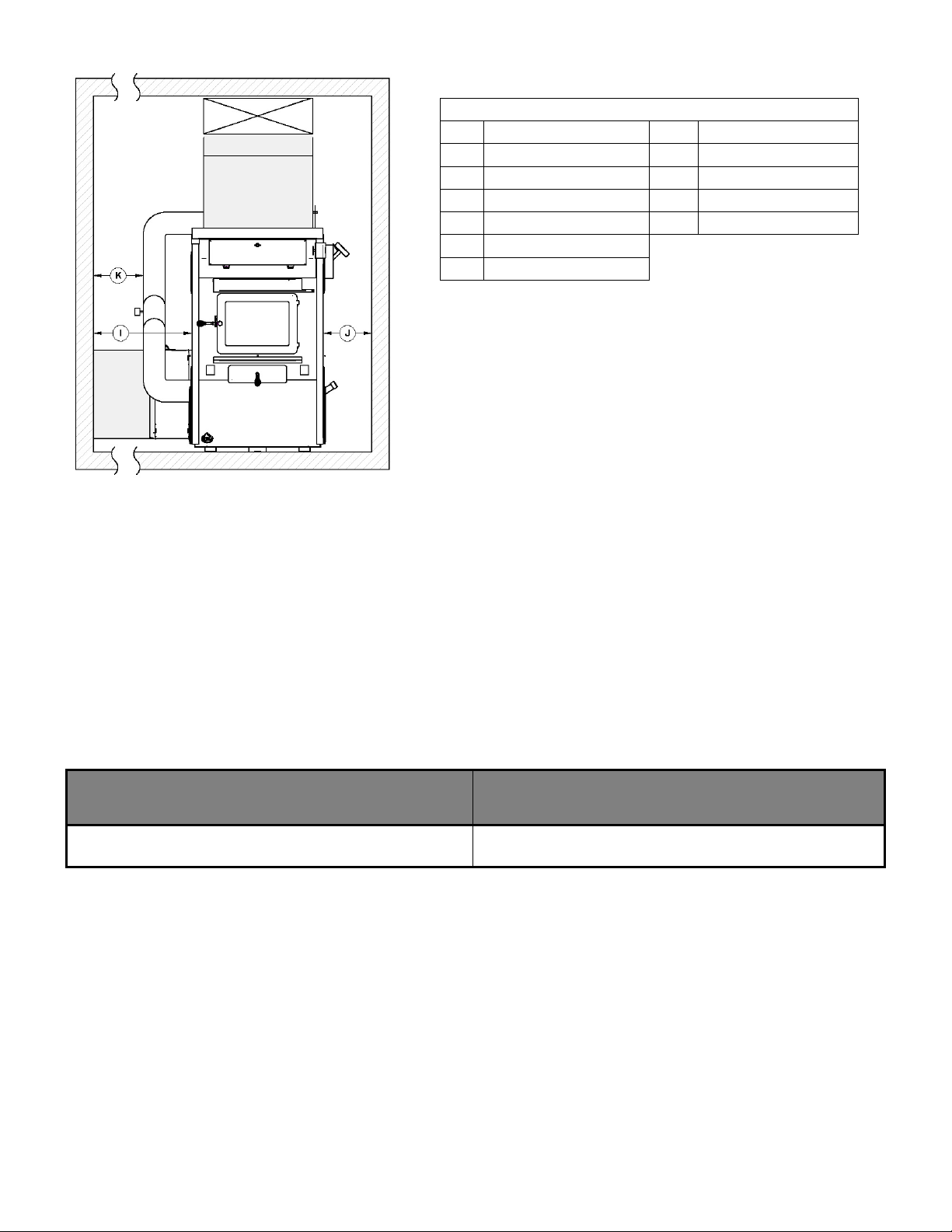
MIMINUM CLEARANCES
A
B
C
D
E
F
-1- HEAT SHIELD
24" (610 mm)
18" (457 mm)
6" (152 mm)
1" (25 mm)
72" (1829 mm)
24" (610 mm)
G
H
I
J
K
8" (203 mm)
1.5" (mm)
24" (610mm)
24" (610mm)
9" (229mm)
22.4. FLOOR PROTECTION
See Section 9.7.4 - FLOOR PROTECTION
22.5. HOT AIR PLENUM
See Section 9.12 - HOT AIR PLENUM
22.6. CONNECTING PIPE AND MANUAL DAMPER
The pipe connecting the furnace to the chimney must be as short and as straight as possible. If a deviation is required,
the use of 45o elbows is highly recommended for a better evacuation of the smoke in the chimney of the wood burning
furnace. The barometric damper provided with the appliance must be installed on the oil unit evacuation pipe,
approximately 24" from the flue outlet of the unit.
TYPE OF FURNACE
OIL BURNING UNIT FLUE
PIPE DIAMETER
MAX CADDY 5"
54
Page 55
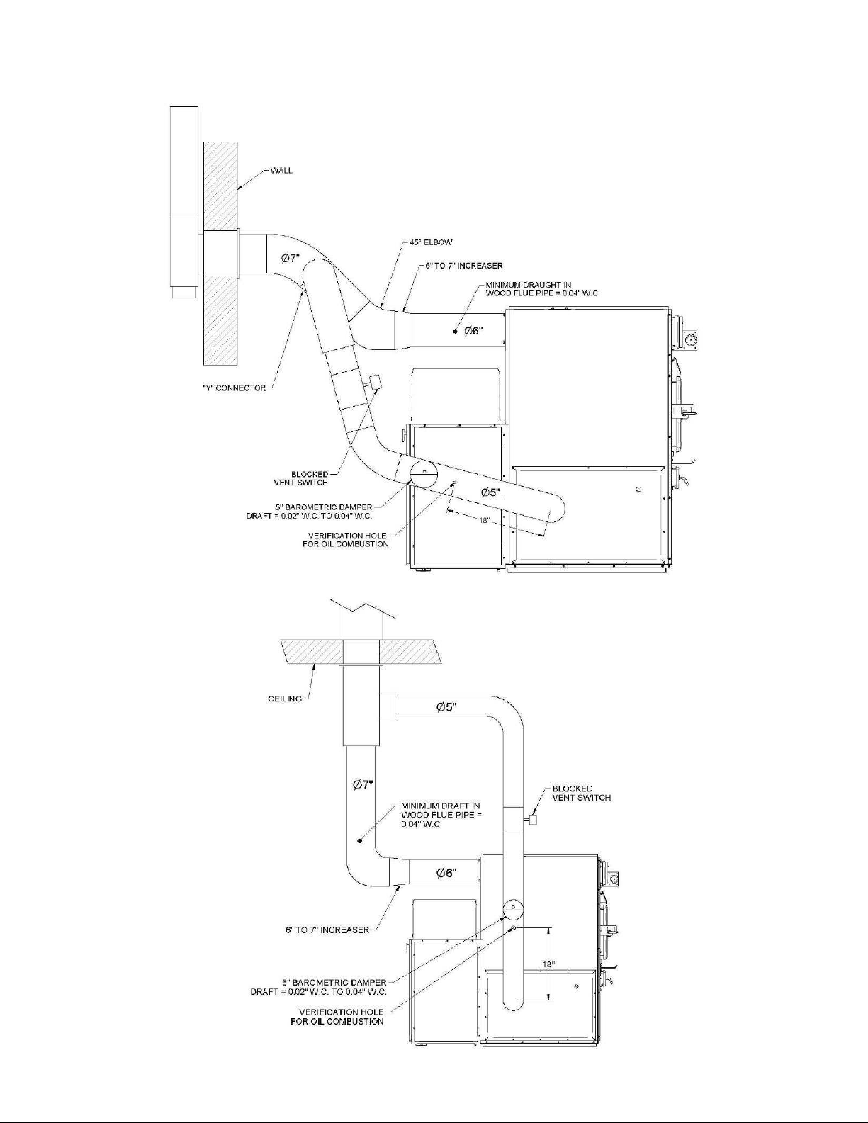
22.7. DIFFERENT INSTALLATION
55
Page 56

22.8. COMBUSTION AIR
See Section 9.11 - COMBUSTION AIR AND FRESH AIR INTAKE ADAPTER INSTALLATION (OPTIONAL)
22.9. ELECTRICAL WIRING
See Section 9.9 - ELECTRICAL CONNECTIONS
22.10. THERMOSTAT
See Section 10 - THERMOSTAT INSTALLATION
23. OPERATION INSTRUCTION
23.1. FAN SPEED CONTROL
See Section 11.5 - DISTRIBUTION BLOWER SPEED CONFIGURATION
23.2. COMBUSTION SAFETY CONTROL
The AFG type oil burner is equipped with an electronic control including a pre-purge function and a new, more durable
drive motor.
23.3. PRE-PURGE
When there is a call for heat, the burner’s fan will run for 15 seconds before the actual ignition takes place to vent the
combustion chamber and generate a proper draft. This will result in a smoother ignition of the oil burner.
23.4. SAFE OPERATION
If the flame goes out while the burner is running, the control will then switch to the "RECYCLE" mode and cut the fuel
supply to the burner for 60 seconds. After this delay, the control goes back to "IGNITION" mode. If the flame goes out
3 times in a row, the control will switch to the "LOCKOUT" mode to prevent a continuous cycling of the ignition process,
which would cause a premature soot-up of the combustion chamber and smoke pipe. To deactivate the “LOCKOUT”
mode, press and hold the reset button of the control for 30 seconds.
A green diagnostic light on the control has four states:
- On = Flame present
- Off = No flame
- 2 seconds On, 2 seconds Off = "Recycle" mode
- 1/2 second On, 1/2 second Off = "Lockout" mode TEMPORARY SHUT-OFF
23.5. TEMPORARY DISENGAGEMENT OF THE BURNER
By pressing and holding the reset button, the burner will shut-off until the reset button is released. When the button is
released, the control will start over at the beginning of the normal cycle.
FOR ADDITIONAL INFORMATIONS ON OPERATION SEQUENCES OF THE BURNER, CONSULT THE BURNER
INSTRUCTION MANUAL.
56
Page 57

23.6. COMBUSTION ADJUSTMENT AND VERIFICATION
To enjoy the efficiency of our oil burning units, you must
respect the following criterion:
Oil burning units must be connected to flue pipes having
at all times a sufficient draft to ensure an efficient and
safe operation of unit.
Before turning on the oil unit, make sure that the sealed
vision cap (SE53352) is installed and secured on the
vision tube with the screw provided. The chamber is
calibrated so that there is a slight positive pressure, which
optimizes the efficiency of combustion. The presence of
the sealed vision cap thus prevents the return of oil odor.
CHECK LIST:
- SELECTION OF NOZZLE AND HEAD
- NOZZLE / ELECTRODES POSITION IN RELATION TO THE HEAD
- PUMP PRESSURE
- OIL LINE IS BLEED.
- FAN SPEED
- BAROMETRIC DAMPER POSITION
TOOLS REQUIRED:
- DRAFT GAUGE
- SMOKE TESTER
- PUMP PRESSURE GAUGE
- NOZZLE AND ELECTRODES POSITION TESTER
- COMBUSTION TESTER
23.6.1. COMBUSTION VERIFICATION PROCEDURE:
A- DRILL A 9/32" DIAMETER HOLE IN THE EVACUATION PIPE APPROXIMATELY 18" FROM THE OUTLET.
B- CLOSE THE DOOR AND THE AIR INTAKE(S) OF THE WOOD BURNING FURNACE.
C- LIGHT THE BURNER FOR AT LEAST 10 TO 15 MINUTES.
D- OVER THE FIRE DRAFT = 0.01 TO 0.02 IN.W.C. (THE DRAFT OVER THE FIRE MUST BE MEASURED BY
THE SCEALED CAP OF THE VISION TUBE’S PULSATION TRAP).
E- SMOKE TEST BETWEEN 0 AND 1 ON THE SHELL BACHARACH SCALE (TRACES).
F- DRAFT IN THE CHIMNEY = 0.02 IN.W.C.
G- PERCENTAGE OF EXCESS AIR = 20 TO 40%, 12% CO2, 5% O2.
H- AVERAGE EFFICIENCY OF 83% TO 87% BASED ON THE TYPE OF BURNER AND ITS INPUT (SEE
SECTION 24.1 I- BURNER’S AIR ADJUSTEMENT: 0-7. TIGHTEN ALL THE LOCKING SCREWS AFTER COMPLETING THE
FINAL ADJUSTMENT.
N.B. The barometric damper provided with the appliance must be properly installed on the flue pipe of the oil burning
unit. The purpose of the damper is to adjust the draft in the evacuation pipe of the oil burning unit to the
recommended level. Since the evacuation pipe of the oil burning unit is connected on the evacuation pipe of the
wood burning furnace, the minimum draft to be respected is 0.04 IN.W.C. in the evacuation pipe of the wood
burning side, at all times. In fact, a barometric damper that would be opened too wide could cause an
important loss of draft in the evacuation pipe of the wood burning furnace.
UH –MAX CADDY
.
57
Page 58
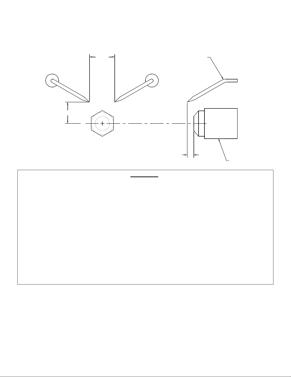
23.6.2. ELECTRODES SETTING
The electrodes must be adjusted by a qualified technician. A proper positioning of the electrodes is important to get an
efficient lighting of the oil.
ELECTRODE SETTING FOR "F" HEAD
5/32"
7/16"
1/16"
ELECTRODE
NOZZLE
WARNING:
1. REFER TO THE RATING PLATE FOR THE PUMP PRESSURE AND THE NOZZLE TYPE.
2. REFER TO THE OIL BURNER’S INSTRUCTIONS MANUAL FOR DETAILS ON THE PUMP.
3. FOR ELECTRODES SETTING, SEE THE OIL BURNER’S MANUAL.
4. FOR THE START-UP AND ADJUSTMENT OF THE BURNER, SEE OIL BURNER’S
INSTRUCTION MANUAL.
5. THE BURNER WILL PROVIDE YEARS OF EFFICIENT OPERATION IF IT IS
PROFESSIONALLY INSTALLED AND MAINTAINED BY A QUALIFIED SERVICE
TECHNICIAN. IF AT ANY TIME THE BURNER DOES NOT APPEAR TO BE OPERATING
PROPERLY, IMMEDIATELY CONTACT YOUR QUALIFIED SERVICE AGENCY FOR
CONSULTATION.
6. FOR MORE DETAILS ABOUT THE BURNER, REFER TO THE BURNER’S MANUAL.
58
Page 59

23.7. APPLIANCE START-UP
NOTE: THE UNIT’S MAINTENANCE, REPAIRS AND THE CLEANING OF
The start-up must be performed by a qualified technician. Make sure the installation is completed and the oil tank has
been filled up. The oil line must also have been purged.
CAUTION: CLOSE THE BLOWER COMPARTMENT ACCESS PANEL BEFORE STARTING THE BURNER.
23.8. PROLONGED CLOSING
A) Cut off the electric circuit
B) Close the oil shut-off valve
NOTE: THE SHUT-OFF VALVE MUST BE CLOSED WHEN THE APPLIANCE IS OUT OF SERVICE FOR A
PROLONGED PERIOD OF TIME.
24. TECHNICAL DATA
24.1. UH –MAX CADDY
MODEL
UH–
MAX
BECKETT AFG 91,000
CADDY
UH–
MAX
BECKETT AFG 120,000
CADDY
UH–
MAX
CADDY
CADDY
RIELLO 40 F3 91,000
UH–
MAX
RIELLO 40 F3 120,000
BURNER
TYPE
BTU
INPUT
NOZZLE FLOW HEAD
0.65, 700W
(DELAVAN)
0.65, 700W
(DELAVAN)
0.50, 700W
(DELAVAN)
0.65, 700W
(DELAVAN)
0.65 GAL US/H
(2.46 L-H)
0.86 GAL US/H
(3.26 L-H)
0.60 GAL US/H
(2.27 L-H)
0.84 GAL US/H
(3.18 L-H)
STATIC
PLATE
F0 ---
F0 ---
--- ---
--- ---
PRESSURE
AT THE PUMP
100 PSI
(690 kPa)
175 PSI
(1205 kPa)
150 PSI
(1035 kPa)
165 PSI
(1135 kPa)
H.P. FAN
MOTOR
1/2 --- 0/7 85%
1/2 --- 1/6 83%
1/2 1 2.5 87%
1/2 1 2.5 85%
TUBULATOR
ADJUSTMENT
AIR
ADJUSTMENT
EFFICIENCY
For any additional information, consult the rating plate on the left hand side of the appliance.
25. MAINTENANCE
At the beginning of heating season, have the complete installation inspected by a qualified service man,
especially the lighting system and the controls.
THE OIL FILTER MUST BE DONE BY A QUALIFIED TECHNICIAN.
25.1. MAINTENANCE
WARNING: TURN OFF ELECTRIC POWER SUPPLY BEFORE SERVICING THE UNIT.
1. The furnace, the burner and the flue pipe should be cleaned at least once a year.
2. The nozzle should be inspected and replaced if needed.
3. Handle the nozzle with care to avoid damaging its surface.
4. The electrodes should be adjusted as indicated in the burner manual.
5. Lubricate the burner motor bearings twice a year. (2 or 3 drops of SAE 20 non detergent lubricating oil).
6. The oil filter should be verified annually and replaced if needed.
59
Page 60

25.2. SERVICE
Before calling for service, first check the following
- Fuel supply
- Electric fuses or breakers
- Thermostat setting
- PC board settings
- The state of the green diagnostic LED on the burner control.
Burner no.: _________________ Model: _______________ Date of installation: ___________________
Service telephone no.: Day: _________________________ Night: _____________________________
Dealer’s name and address: ____________________________________________________________
TEST REPORT :
CO2 _____________% Temp. at stack: ___________________ Draft at stack: _______________IN.W.C.
Nozzle output: _______________________ GPH Smoke colour: ______________________________
Inspected by : _______________________________________________________
25.3. FILTERS
See Section 12.5 - FILTERS
60
Page 61

26. ELECTRICAL DIAGRAM BECKETT OIL UNIT
61
Page 62
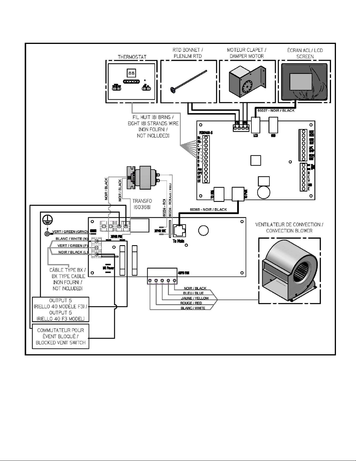
27. ELECTRICAL DIAGRAM RIELLO OIL UNIT
62
Page 63
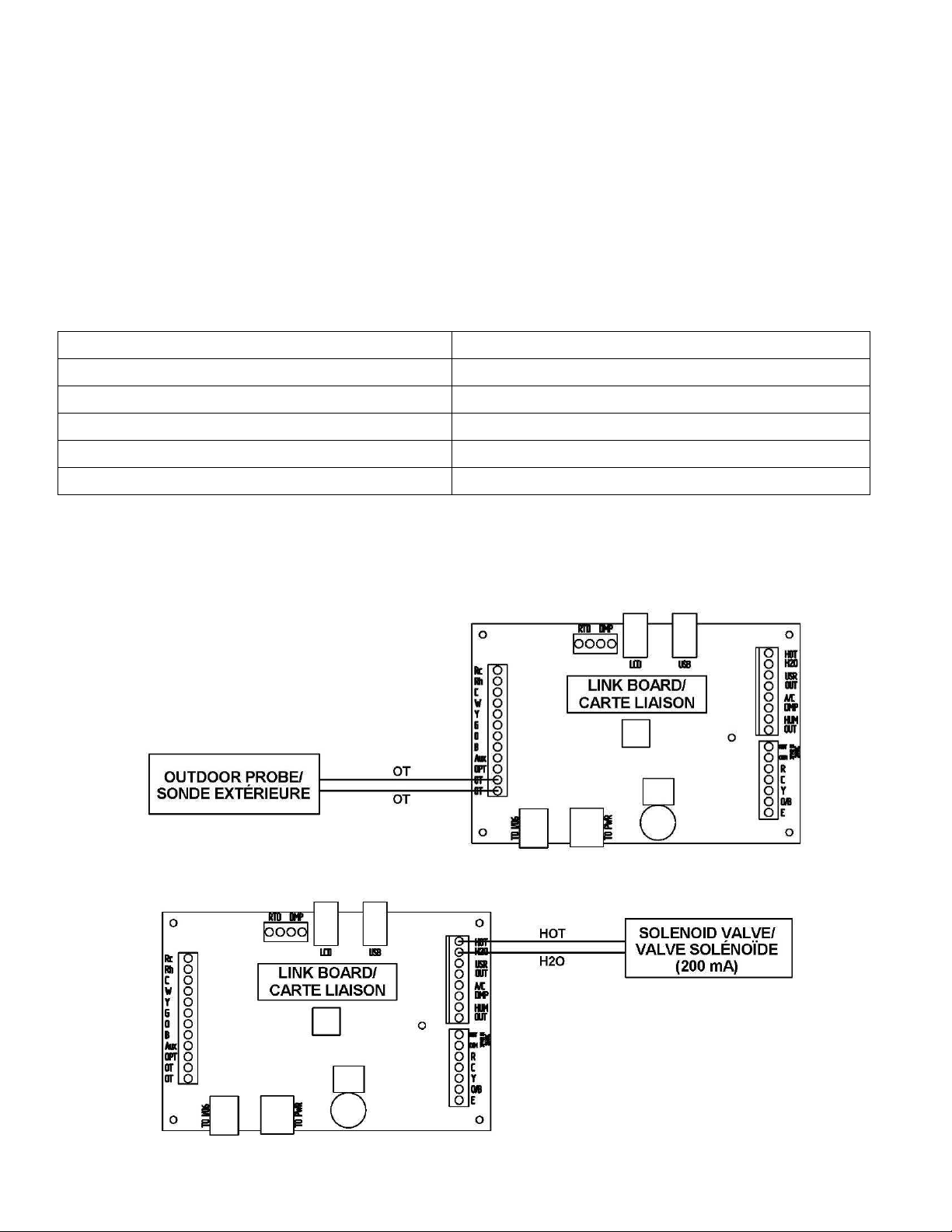
28. LINK BOARD OPTIONS CONNECTIONS
28.1. ELECTRICAL CONSUMPTION
Your Max Caddy furnace is able to supply electrical 24V current to control various options. The options that can be
supported are described in the table below. The maximum available 24V current is 1.66 amps (transformer 24V @
40VA). The table below shows the approximate electrical consumption of each of the options that can be installed with
your Max Caddy furnace. It is important to note that those consumptions were determined according to the maximum
consumption of the options tested by the manufacturer. It is possible to find on the market options having higher or
lower electrical consumption than those shown in the table below. In the event that the combined electrical
consumption of the installed options is higher than 1.66 amps, contact our technical support for further information.
WARNING: INCORRECT WIRING CAN DAMAGE THE LINK BOARD.
Option Approximate consumption (mA)
Additional 24V equipment 500
Air conditioning damper 500
Humidifier 500
Heat pump Current supply via additional transformer (not provided)
Thermostat (if not battery powered) 500
* It is important that the sum of the electrical consumption of the installed options is not higher than 1.66 amps.
28.2. OUTDOOR PROBE
* The outdoor probe act as a switch therefore it does not consumes electrical current.
28.3. HOT WATER
63
Page 64
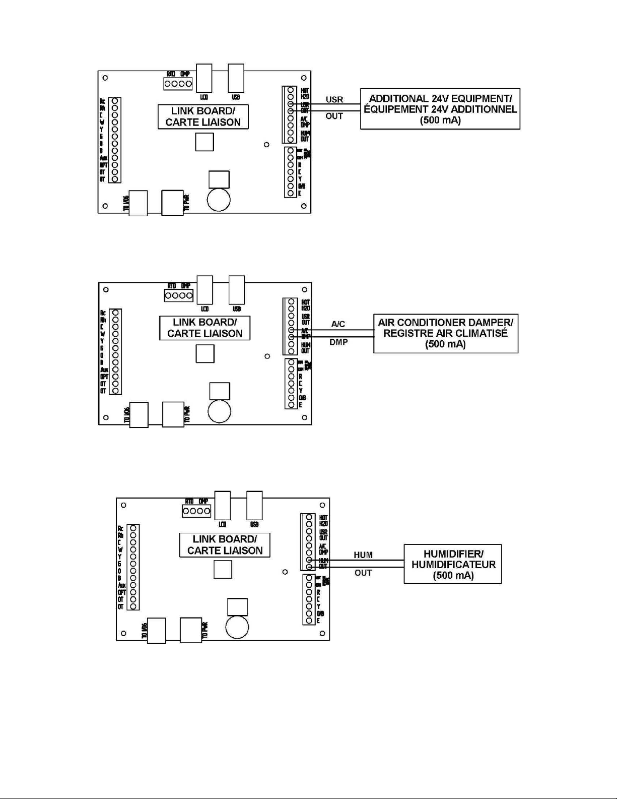
28.4. 24V ADDITIONNAL EQUIPMENT
28.5. AIR CONDITIONNING DAMPER
28.6. HUMIDIFIER
64
Page 65

28.7. HEAT PUMP
29. EXPLODED VIEW AND PART LIST
65
Page 66
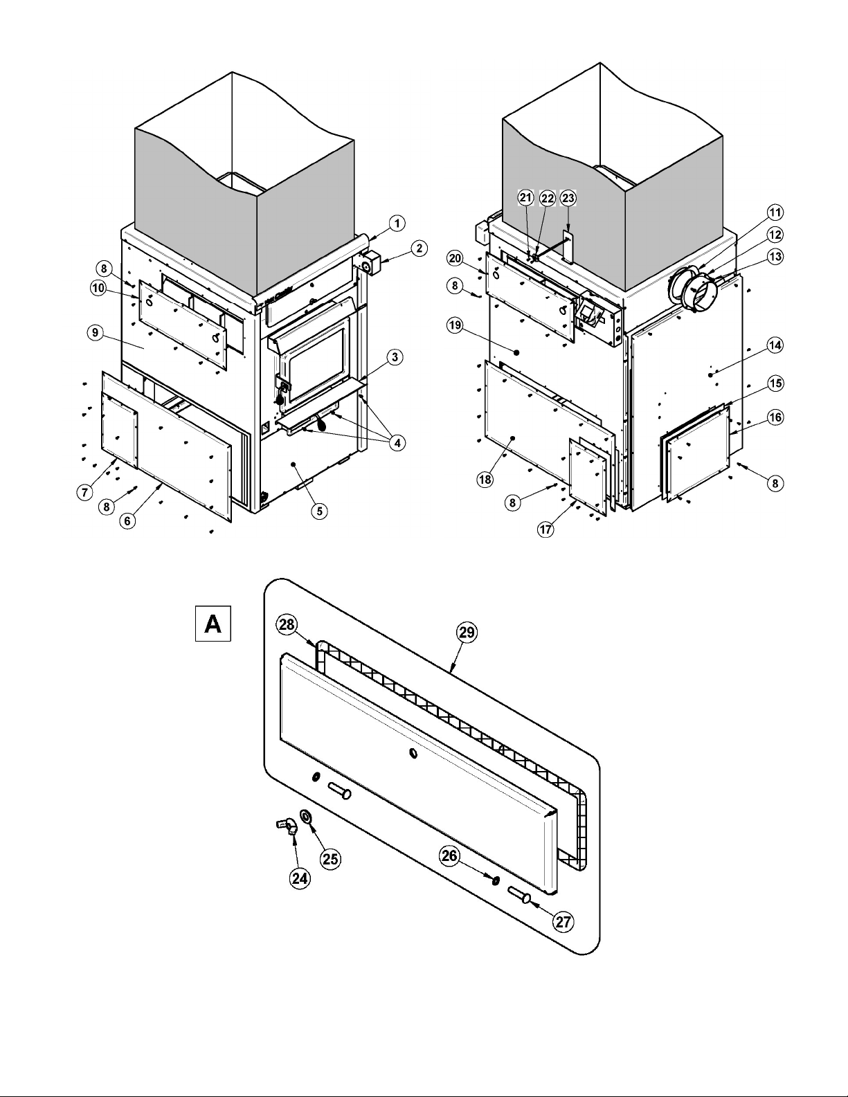
66
Page 67
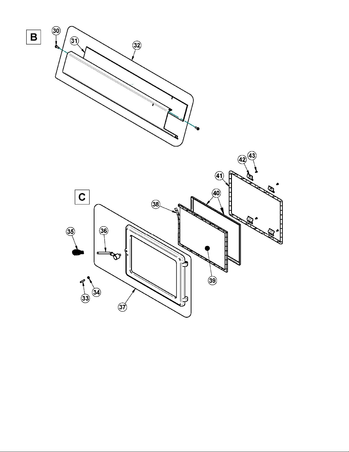
67
Page 68
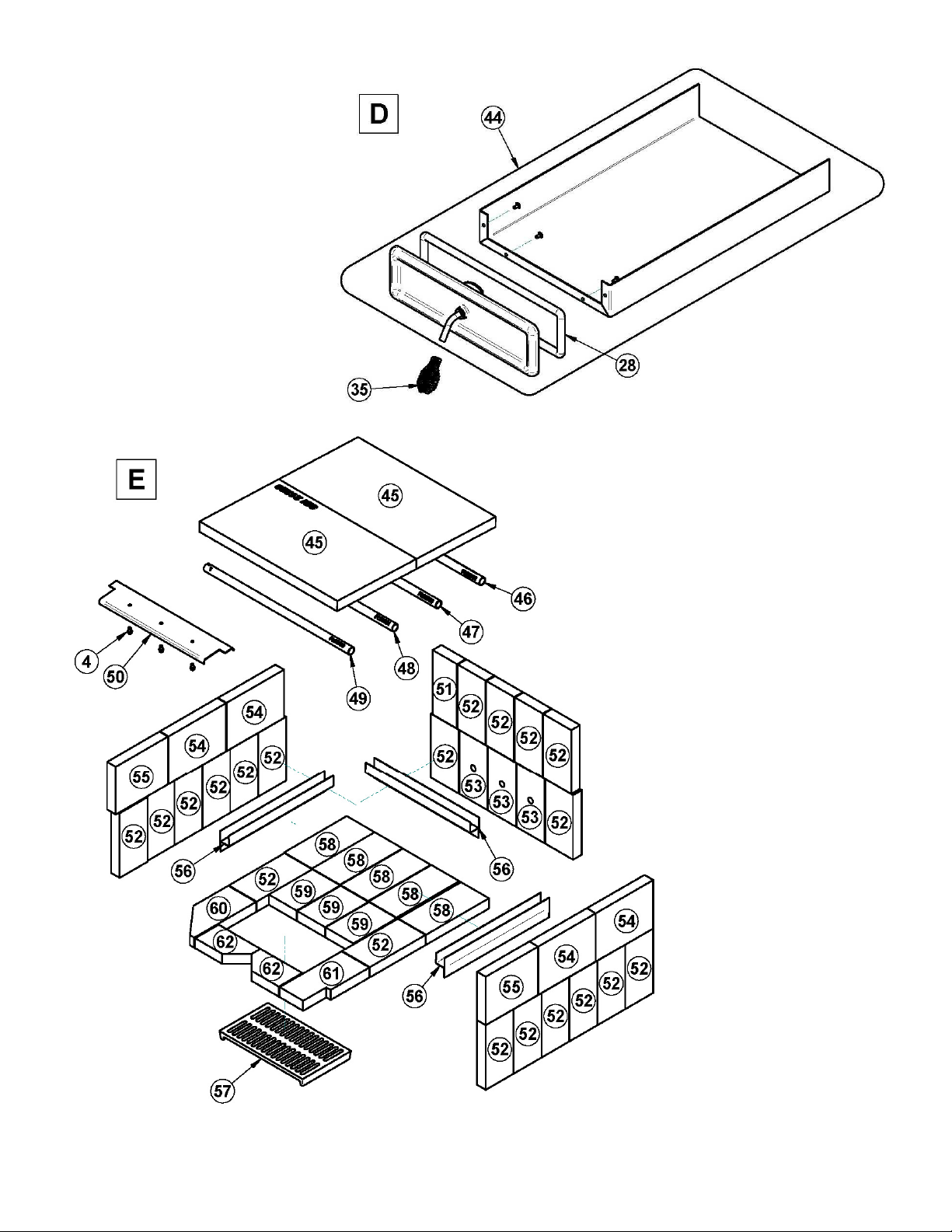
68
Page 69
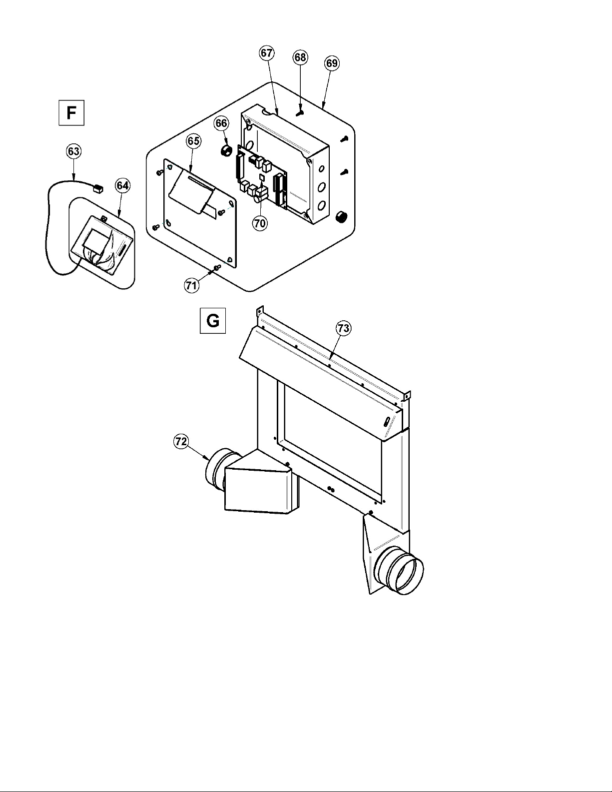
69
Page 70

70
Page 71
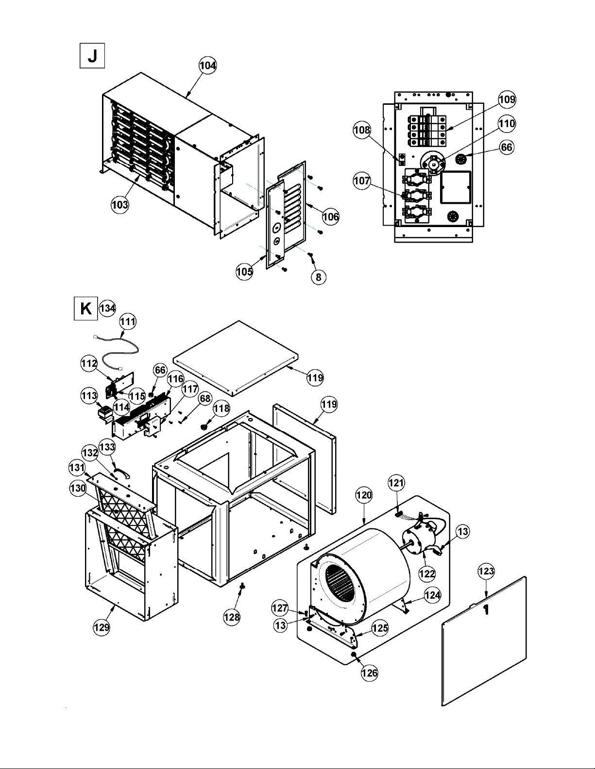
71
Page 72
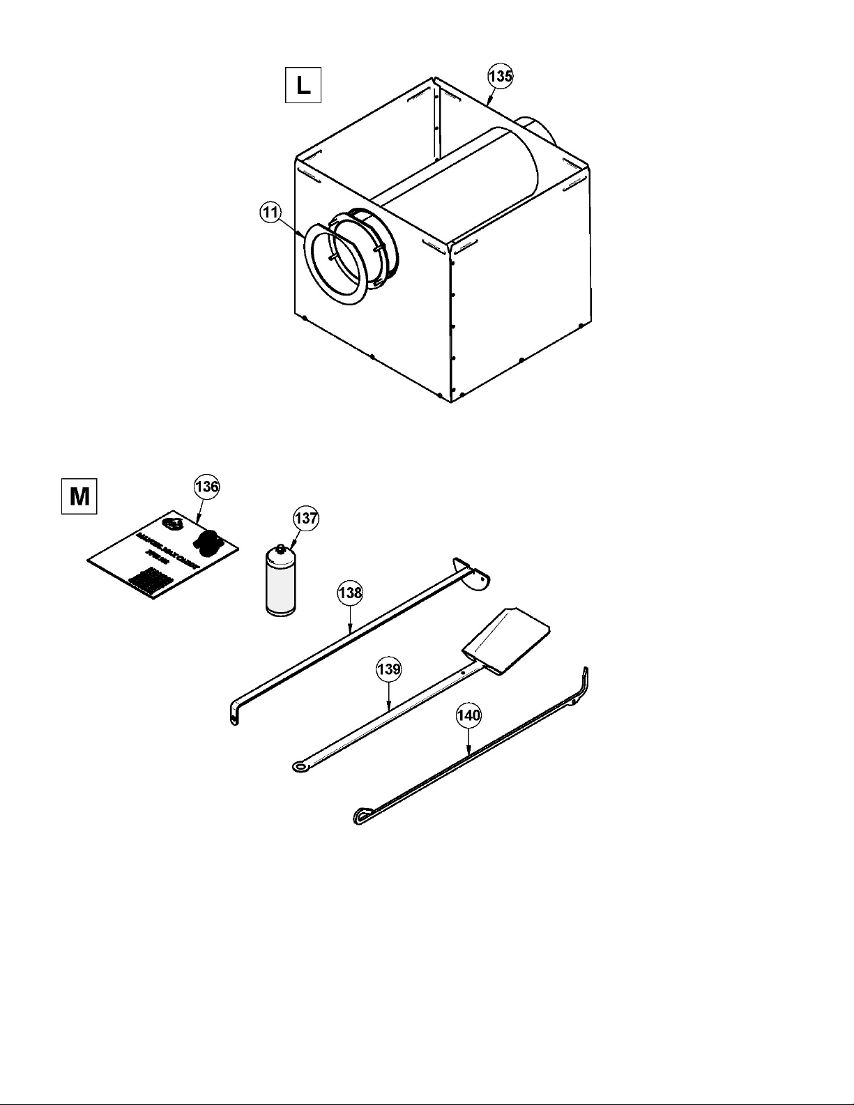
72
Page 73

IMPORTANT: THIS IS DATED INFORMATION. When requesting service or replacement parts for your stove, please
provide the model number and the serial number. We reserve the right to change parts due to technology upgrade or
availability. Contact an authorized dealer to obtain any of these parts. Never use substitute materials. Use of nonapproved parts can result in poor performance and safety hazards.
# Item Description Qty
1 PL56400 DECORATIVE MOULDING 1
2 51000 HONEYWELL 24V DAMPER MOTOR 1
3 PL56276 ASH SHELF 1
4 30060 THREAD-CUTTING SCREW 1/4-20 x 1/2" F HEX STEEL SLOT WASHER C102 ZINC 3
5 PL56403 AIR JACKET FRONT BOTTOM PANEL 1
6 PL56412 LEFT PANEL FOR THE ELECTRICAL ELEMENT OPTION 1
7 PL56413 LEFT ACCESS COVER FOR ELECTRICAL ELEMENT 1
8 30131 BLACK METAL SCREW #10 X 1/2" TYPE "A" PAN QUADREX 1
9 SE56406 AIR JACKET LEFT PANEL WITH INSULATION 1
10 SE56415 LEFT PANEL WITH INSULATION WATER LOOP OPTION 1
11 21221 CHIMNEY ADAPTER GASKET 1
12 SE56352 FLUE COLLAR ASSEMBLY 1
13 30094 HEX SCREW WASHER HEAD 1/4-20 X 3/4" F ZINC TYPE 3
14 SE56408 REAR AIR JACKET PANEL 1
15 21342 REAR COVER GASKET 1
16 PL56480 REAR CABINET COVER 1
17 PL56411 RIGHT ACCESS COVER FOR ELECTRICAL ELEMENT 1
18 PL56410 RIGHT PANEL FOR THE ELECTRICAL ELEMENT OPTION 1
19 SE56407 RIGHT AIR JACKET PANEL WITH ISULATION 1
20 SE56414 RIGHT PANEL WITH INSULATION WATER LOOP OPTION 1
21 30153 METAL SCREW #8 X 1/2" PAN SQUARE TEK BLACK SELF DRILLING 2
22 SE44096 100 OHM RTD PROBE 38" WIRE WITH CONNECTOR 1
23 PL56343 RTD SUPPORT BRACKET 1
24 30416 WING NUT 3/8"-16 1
25 30205 ZINC WASHER ID 13/32" X OD 13/16" 4
26 30055 HINGE PIN RETAINING RING 5/16" ID X 0.512" OD 2
27 30168 HINGE PIN 5/16 DIA. X 1 1/4" L 2
28 AC06900 BLACK 1/2'' ROUND X 9' GASKET KIT WITH ADHESIVE 1
29 SE56405 HEAT EXCHANGER ACCESS DOOR 1
30 30502 SELF TAPING SCREW #8 - 32 X 1/2" TYPE F X 3/4 HEX FLAT HEAD 2
31 21341 AIR CONTROL PLATE INSULATION 1
32 SE56322 PRIMARY AIR DAMPER ASSEMBLY 1
33 30128 SOCKET SET SCREW 1/4"-20 X 1 1/4" 1
34 30100 BLACK HEX NUT 1/4 - 20 1
35 30429 3/8'' NICKEL COIL HANDLE 1
36 AC09151 REPLACEMENT HANDLE KIT 1
37 SE24027 MAX CADDY CAST IRON DOOR WITH HANDLE 1
38 AC06400 3/4" (FLAT) X 6' BLACK SELF-ADHESIVE GLASS GASKET 1
39 SE56287 REPLACEMENT GLASS WITH GASKET 10 7/8" X 15 1/8" 1
40 PL56285 GLASS RETAINER 2
41 OA11400 SILICONE AND 3/4" X 8' GASKET KIT 1
42 PL51351 GLASS RETAINER FRAME BRACKET 4
73
Page 74

# Item Description Qty
43 30124 SCREW #8 - 32 X 5/16'' TRUSS QUADREX ZINC 4
44 SE56274 ASH DRAWER 1
45 21220 C-CAST BAFFLE 19 3/4" X 11 3/8" X 1 1/4" 2
46 PL56764 REAR SECONDARY AIR TUBE 1
47 PL56763 MIDDLE REAR SECONDARY AIR TUBE 1
48 PL56761 MIDDLE FRONT SECONDARY AIR TUBE 1
49 PL56760 FRONT SECONDARY AIR TUBE 1
50 PL56356 PRIMARY AIR DEFLECTOR HEAT SHIELD 1
51 PL36119 3 1/2" X 8" X 1 1/4" REFRACTORY BRICK 1
52 29001 4'' X 8 1/8'' X 1 1/4'' REFRATORY BRICK HD 20
53 21343 4'' X 8'' X 1 1/4'' REFRACTORY BRICK WITH HOLE 3
54 29005 6" X 8 1/4" X 1 1/4'' REFRACTORY BRICK HD 4
55 PL36231 6" X 7 1/2" X 1 1/4" REFRACTORY BRICK 2
56 PL56286 BRICK RETAINER 3
57 24099 CAST IRON ASH GRATE 12" X 7" 1
58 29011 4'' X 9" X 1 1/4" REFRACTORY BRICK HD 5
59 PL36234 4" X 6 1/4" X 1 1/4" REFRACTORY BRICK 3
60 PL36059 CUT BRICK 4" X 8 7/8" X 3 3/8" X 3 7/8" 1
61 PL36232 4" X 8 3/4" X 1 1/4" X 1/2" X 3 1/4 REFRACTORY BRICK 1
62 PL36233 3 1/2" X 6" X 1 1/4" REFRACTORY BRICK 2
63 60327 JUNCTION WIRE MAIN CONTROL BOARD TO LCD 1
64 SE56777 MAX CADDY TOUCH SCREEN BOARD (LCD) WITH HOUSING 1
65 PL48251 PC BOARD HOUSING COVER 1
66 30412 BLACK UNIVERSAL SNAP-IN BUSHING 1
67 PL48250 PC BOARD HOUSING 1
68 30408 ELECTRONIC BOARD CLIP 9
69 SE56823 POWER BOARD HOUSING ASSEMBLY 1
70 PL56823 LIMIT MAIN CONTROL BOARD WITH PROGRAM 1
71 30154 BLACK SCREW #10 X 5/8" ROBERTSON TYPE A 4
72 49068 ADAPTER 5'' FOR FRESH AIR INTAKE KIT 2
73 PA08560 5" FRESH AIR INTAKE ADAPTER 1
74 PA08550 HOT WATER LOOP KIT FOR PRE-HEATING OF DOMESTIC WATER 1
75 PL56466 LEFT OIL UNIT PANEL 1
76 60201 CONNECTOR 1 SCREW 3/8" FOR BX WIRE 1
77 60216 ELECTRICAL CABLE BX 14/2 50-003-500 1
78 49021 5'' PIPE WITH 41/64 HOLE FOR WMO-1 SAFETY DEVICE 1
79 SE48210 BLOCKED FLUE OIL UNIT SWITCH 1
80 51018 BAROMETIC DAMPER 6", 7" AND 8" 1
81 44134 MILLIVOLT THERMOSTATS - WHITE 1
82 30026 THREAD CUTTING SCREW 10-24 F 5/8" HEX WASHER HEAD 4
83 PL56435 OIL UNIT LEG 2
84 30095 SET SCREW HEX 1/4-20 X 1/4'' 1
85 SE53352 SEALED VISION CAP 1
86 SE56420 MAX CADDY OIL COMBUSTION CHAMBER 1
87 PL56345 OIL COMBUSTION CHAMBER REAR DEFLECTOR 1
88 30092 BOLT 5/16''-18 X 3/4" HEX GRADE 5 12
74
Page 75

# Item Description Qty
89 21079 OIL UNIT COVER GASKET 1
90 SE53269 OIL UNIT COVER ASSEMBLY WITH VISION TUBE 1
91 30210 WASHER 29/32" OD X 3/8" ID ZINC 12
92 30425 NUT BRASS 5/16 - 18 HEX 12
93 21085 BURNER / OIL UNIT GASKET 1
94 30423 3/8'' - 16 HEX ZINC NUT 3
95 PL56465 RIGHT OIL UNIT PANEL 1
96 51024 NOZZLE DELAVAN .65GPH X 70° W 1
97 60043 BECKETT CLEANCUT OIL PUMP WITH SOLENOID 1
98 44019 PRIMARY CONTROL HW 1
99 44018 CAD CELL BECKETT BURNER 1
100 44023 BECKETT BURNER IGNITOR (TRANSFO) 1
101 51007 RIELLO OIL BURNER 1
101 51006 BECKETT AFG BURNER 1
102 PA08512 BECKETT OIL UNIT 1
102 PA08511 RIELLO OIL UNIT 1
103 60253 10 kW ELECTRICAL ELEMENT (DOUBLE 5 kW) 1
103 60245 SINGLE 5 kW ELECTRIC ELEMENT 1
104 PA08535 20 kW ELECTRICAL ELEMENT 1
104 PA08545 25 kW ELECTRICAL ELEMENT 1
105 PL56507 LEFT COVER OF ELECTRICAL UNIT 1
106 PL56508 AERATION COVER ELECTRICAL UNIT 1
107 60202 SEQUENCER 15S X 441 1
108 60207 ALUMINUM LUG 14-6 STUD 17/64 1
109 60194 FUSE HOLDER 30A. 600V PROTECTION 1
110 60237 THERMODISC L170 MANUAL RESET FOR ELECTRICAL ELEMENT 1
111 60365 60'' COMMUNICATION WIRE - 8 CONDUCTOR 1
112 44182 TRIAC BOARD 1
113 60368 TRANSFORMER 120 V/24 V 40 VA 1
114 44136 FUSE 12A / 250V / 1/4" DIA. X 1 1/4'' L 1
115 44137 FUSE 1A / 250V / 1/4" DIA. X 1 1/4'' L 1
116 PL48243 POWER BOARD HOUSING 1
117 PL48242 POWER BOARD ACCESS PANEL 1
118 30406 BLACK SNAP-ON BUSHING 1 3/4" X 7/8" X 1" 1
119 PL56417 BLOWER BOX REMOVABLE COVER 1
120 SE56512 FAN ASSEMBLY WITH 1/2 HP DD MOTOR 1
121 44186 5 POSITIONS TERMINAL BLOCK 1
122 51038 1/2 HP 4 SPEED MOTOR FOR G-10 DD 1
123 SE56419 BLOWER ACCESS DOOR ASSEMBLY 1
124 30334 LEFT HOUSING SUPPORT FOR G10 BLOWER 10-458-085 1
125 30336 RIGHT HOUSING SUPPORT FOR G10 BLOWER 1
126 30335 BLOWER ANTI-VIBRATION CUSHION 4
127 30109 BOLT HEX 1/4 - 20 X 1" 4
128 30536 LEVELING BOLT 1/4 - 20 X 1'' 2
129 SE56418 DUCT SUPPORT ASSEMBLY 1
130 21231 CARDBOARD AIR FILTER 20" X 16" X 1" 1
75
Page 76

# Item Description Qty
131 SE56450 FILTER DRAWER 1
132 30108 MECHANICAL SCREW M4 X 4MM PAN PHILLIPS ZINC 2
133 28062 BLACK DRAWER HANDLE 3 25/32" 1
134 PA08566 BLOWER ASSEMBLY 1
135 PA08500 TOP AIR RETURN PLENUM KIT 1
136 SE45833 MAX CADDY INSTRUCTION MANUAL KIT 1
137 AC05961 PSG GREY 424C SPRAY PAINT 1
137 AC05963 METALLIC BLACK STOVE PAINT - 85 g (3oz) AEROSOL 1
138 PL48170 HEAT EXCHANGER SCRAPER 1
139 PL48171 ASH SHOVEL 1
140 PL48173 POKER 1
76
Page 77

WHY PURCHASE THROUGH AN AUTHORIZED PSG DEALER?
To make sure your PSG furnace provides comfort and energy savings in your home for many
years, your choice of installer is extremely important. An authorized PSG dealer will ensure that the
system is optimized and installed according to standards. Given the importance of the installation,
PSG recommends that it is carried out by a professional certified in the Building Code so that the
furnace delivers its full potential. This is why PSG offers an additional warranty that covers the cost
of labor if your furnace has been purchased through an authorized PSG dealer.
If you want to enjoy the best service on the market and substantial savings on heating costs, there
is really only one choice: an Authorized PSG Dealer.
77
Page 78

PSG LIMITED LIFETIME WARRANTY (REGULAR)
The warranty of the manufacturer extends only to the original consumer purchaser and is not transferable. This
warranty covers brand new products only, which have not been altered, modified nor repaired since shipment from
factory. Proof of purchase (dated bill of sale), model name and serial number must be supplied when making any
warranty claim to your PSG dealer.
This warranty applies to normal residential use only. Damages caused by misuse, abuse, improper
installation, lack of maintenance, over firing, negligence or accident during transportation, power failures,
downdrafts, or venting problems are not covered by this warranty.
This warranty does not cover any scratch, corrosion, distortion, or discoloration. Any defect or damage caused by the
use of unauthorized parts or others than original parts void this warranty. An authorized qualified technician must
perform the installation in accordance with the instructions supplied with this product and all local and national building
codes. Any service call related to an improper installation is not covered by this warranty.
The manufacturer may require that defective products be returned or that digital pictures be provided to support the
claim. Returned products are to be shipped prepaid to the manufacturer for investigation. If a product is found to be
defective, the manufacturer will repair or replace such defect. Transportation fees to ship the product back to the
purchaser will be paid by the manufacturer. All parts costs covered by this warranty are limited according to the table
below.
The manufacturer at its discretion may decide to repair or replace any part or unit after inspection and investigation of
the defect. The manufacturer may, at its discretion, fully discharge all obligations with respect to this warranty by
refunding the wholesale price of any warranted but defective parts. The manufacturer shall in no event be responsible
for any special, indirect, consequential damages of any nature, which are in excess of the original purchase price of the
product. A one-time replacement limit applies to all parts benefiting from a lifetime coverage. This warranty applies to
products purchased after April 1st, 2013.
DESCRIPTION
Castings, combustion chamber (welds only), castings, and heat exchanger
(welds only).
Stainless steel firebox components, secondary air tubes*, surrounds and heat
shields, ash drawer, and plating* (defective manufacture).
Carbon steel firebox components, glass retainers, handle assembly, C-Cast
baffle*, and vermiculite baffle*.
Oil burner, electrical elements, blowers, heat sensors, switches, rheostat, relays,
damper motor, fan limit control, PC board, wiring, and other controls.
Ceramic glass (thermal breakage only*), paint (peeling), gaskets, insulation, and
ceramic fibre blankets.
Firebrick
*Pictures required
Shall your unit or a components be defective, contact immediately your PSG dealer. Prior to your call make sure you
have the following information necessary to your warranty claim treatment:
• Your name, address and telephone number;
• Bill of sale and dealer’s name;
• Serial number and model name as indicated on the
nameplate fixed to the back of your unit;
• Nature of the defect and any relevant information.
WARRANTY APPLICATION
PARTS LABOUR
Lifetime n/a
5 years n/a
3 years n/a
2 years
1 year n/a
n/a
n/a
n/a
Before shipping your unit or defective component to our plant, you must obtain from your PSG dealer an
Authorization Number. Any merchandise shipped to our plant without authorization will be refused
automatically and returned to sender.
78
Page 79

PSG LIMITED LIFETIME WARRANTY (PRIVILEGE)
The warranty of the manufacturer extends only to the original consumer purchaser and is not transferable. This
warranty covers brand new products only, which have not been altered, modified nor repaired since shipment from
factory and purchased through an authorised dealer. Proof of purchase (dated bill of sale), model name and serial
number must be supplied when making any warranty claim to your PSG dealer.
This warranty applies to normal residential use only. Damages caused by misuse, abuse, improper
installation, lack of maintenance, over firing, negligence or accident during transportation, power failures,
downdrafts, or venting problems are not covered by this warranty.
This warranty does not cover any scratch, corrosion, distortion, or discoloration. Any defect or damage caused by the
use of unauthorized parts or others than original parts void this warranty. An authorized qualified technician must
perform the installation in accordance with the instructions supplied with this product and all local and national building
codes. Any service call related to an improper installation is not covered by this warranty.
The manufacturer may require that defective products be returned or that digital pictures be provided to support the
claim. Returned products are to be shipped prepaid to the manufacturer for investigation. If a product is found to be
defective, the manufacturer will repair or replace such defect. Transportation fees to ship the product back to the
purchaser will be paid by the manufacturer. Repair work covered by the warranty, executed at the purchaser’s domicile
by an authorized qualified technician requires the prior approval of the manufacturer. Labour cost and repair work to
the account of the manufacturer are based on predetermined rate schedule and must not exceed the wholesale price
of the replacement part. All parts and labour costs covered by this warranty are limited according to the table below.
The manufacturer at its discretion may decide to repair or replace any part or unit after inspection and investigation of
the defect. The manufacturer may, at its discretion, fully discharge all obligations with respect to this warranty by
refunding the wholesale price of any warranted but defective parts. The manufacturer shall in no event be responsible
for any special, indirect, consequential damages of any nature, which are in excess of the original purchase price of the
product. A one-time replacement limit applies to all parts benefiting from a lifetime coverage. This warranty applies to
products purchased after April 1st, 2013.
DESCRIPTION
Castings, combustion chamber (welds only), castings, and heat exchanger (welds
only).
Stainless steel firebox components, secondary air tubes*, surrounds and heat
shields, ash drawer, and plating* (defective manufacture).
Carbon steel firebox components, glass retainers, handle assembly, C-Cast
baffle*, and vermiculite baffle*.
Oil burner, electrical elements, blowers, heat sensors, switches, rheostat, relays,
damper motor, fan limit control, PC board, wiring, and other controls.
Ceramic glass (thermal breakage only*), paint (peeling), gaskets, insulation, and
ceramic fibre blankets.
Firebrick
*Pictures required
WARRANTY APPLICATION
PARTS LABOUR
Lifetime 3 years
5 years 3 years
3 years 1 year
2 years 1 year
1 year n/a
n/a n/a
Shall your unit or a components be defective, contact immediately your PSG dealer. Prior to your call make sure you
have the following information necessary to your warranty claim treatment:
• Your name, address and telephone number;
• Bill of sale and dealer’s name;
Before shipping your unit or defective component to our plant, you must obtain from your PSG dealer an
Authorization Number. Any merchandise shipped to our plant without authorization will be refused
automatically and returned to sender.
• Serial number and model name as indicated on the
nameplate fixed to the back of your unit;
• Nature of the defect and any relevant information.
79
 Loading...