

Page 1

CADDY CORPORATION
Air SystemsFood Service Equipment
Control Cabinets for
Water-Wash Ventilators
Model CPE
Page 2
18"
50"
END VIEW
22"
32"8"
10"
32"
ELEVATION VIEW
END VIEW
22"
32"8"
10"
32"
ELEVATION VIEW
PROJECT:
ITEM NO:
Control Cabinets for Water-Wash Ventilators
Model CPE
LOCATION:
General Description (Non-sequential)
The CADDYAirSystems Model CPE waterwash control panel is
designed to work in conjunction with series"SH-W" ventilator. This
panel houses all necessary plumbing and electrical components
required to manually control the exhaust fan, operate the wash cycle,
and control the internal fire protection system. Panel to
include____vacuum breaker and check valve shipped loose for
installation by the Plumbing Contractor ____ a built-in reduced
pressure (RP) type backflow preventor as required by the Uniform
Plumbing Code (UPC), state and/or codes.
Model Number Designation
In order to determine the exact panel model number, it is first necessary
to identify which of the following options are desired. Each selected
option becomes an identitiable suffix int eh model number.
1. Number of groups in sequence (if applicable).. 2,3 or 4
2. Built-in backflow preventor (if applicable)......... RP
3. Programmable time clock................................. TC
4. Low detergent alarm......................................... LD
5. Cold water mist................................................. CM
6. Pipe inlet size ( inches)..................................... 75,1.00,1.25 or 1.50
Once options are selected, identify the exact panel model number as
illustrated by the following example:
509 Sharptown Road P.O. Box 345
Bridgeport, NJ 08014-0345
Tel: 856-467-4222 Fax: 856-467-5511
internet: www.caddycorp.com
CADDY CORPORATION
CADDY Air Systems
All specifications subject to change without notice
01/08
General Description (Sequential)
The CADDYAirSystems Model CPE waterwash control panel is
designed to work in conjunction with series"SH-W" ventilator. This the
of panel is typically required when the building hot water system is not
capable of delivering enough hot water to wash hoods during a single
period of time. This panel houses all necessary plumbing and electrical
components required to manually control the exhaust fan, operate the
wash cycle, and control the internal fire protection system. Panel to
include built-in reduced pressure (RP) type backflow preventor as
required by the Uniform Plumbing Code (UPC), state and/or codes.
This panel is designed to wash two or more groups of ventilators in
sequence ( up to four groups maximum), with a programmable delay
period between each group to allow for hot water regeneration. Upon
wash sequence activation, the exhaust fan shuts down automatically,
and the first wash cycle is initiated. At the end of the first wash cycle,
there is a programmable delay of up to 120 minutes. The wash cycle
for the next group begins at the end of the previous delay period. This
sequence of operation continues of up to four groups. The wash cycle
length is factory set at 5 minutes for optimal cleaning. Each wash cycle
duration can be field adjusted from 1-14 minutes, depending upon
internal grease accumulations.
Time Clock Operation (Optional)
Model CPE and CPE-S will include a 24 hour per day, seven day
operation is required. This clock is located within the electrical
compartment of the panel, where it is not subject to tampering.
Features include: LCD digital display, independent daily programming
capability, multiple start fan and start wash times, Holiday skip feature,
power back-up for holding clock setting and daily programming
requirements.
Number of Panels Required
One control panel can be used for multiple hood sections as long as the
total lineal footage of ventilator does not exceed the pipe size limitations
of the panel. (Non-sequential). One control panel can be used for
multiple hoods in a group wash configuration up to four groups,as long
as the total lineal footage of ventilator in each group does no exceed
the pipe size limitations of the panel. (Sequential). See "Hot Water
Pipe Inlet Size" chart below for panel limitations. Any number of
exhaust fans can be interconnected to these panels if simultaneous
operation of fans single control panel, consult factory for wiring details.
CPE -
Prefix
S___ -
No. of Groups
in Sequence
(if Applicable)
RP -
Built-in
Backflow
Preventor
(if Applicable)
TC -
Time
Clock
LD -
Low
Detergent
Alarm
CM -
Cold
Water
Mist
___
Pipe
Size
Installation
The CPE control panel is shipped as a separate component and is to be
installed, wired and plumbed by the applicable field trades. This panel
can be either surface or flush mounted. When flush mounted, specify
panel with stainless steel trim ring.
Hot Water Requirements
140 Deg. F. minimum - 180 Deg. F. maximum
40psi minimum - 80 psi maximum
Average wash cycle duration - minutes per 24 hour period
1.00 FPM per lineal foot of ventilator at 40 psi
1.25 GPM per lineal foot of ventilator at 80 psi
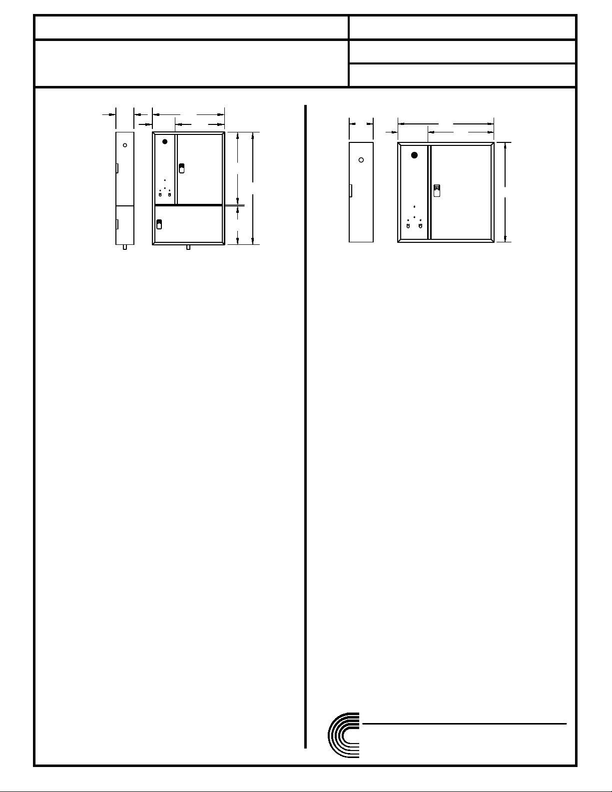
Control Panel Dimensions
All non-sequential panels without built-in backflow preventor are
32" W x 32" H x 8" D
All non-sequential panels with built-in backflow preventor are
32" W x 50" H x 8" D
All sequential panels up to a three sequence configuration (S-3) are
32" W x 50" H x 8" D
All sequential panels with a four sequence configuration (S-4) are
32" W x 54" H x 8" D
Control Panel Weights
All non-sequential panels : 100 LBS.
All sequential panels: 150 LBS.
Electrial Requirments
120 volt, 60 HZ, 15 amp (minimum) non-interrupted service.
MODEL CPE-1.25-RP-TC MODEL CPE-1.25-TC
page 1 of 7
Page 3
12
11
14
13
15
9
3
4
5
16
8
10
7
1
2
6
12:00
PLC.
RELAY STRIPRELAY STRIP
TERMINAL
STRIP
17
14
13
18
16
15
17
10
11
3
4
6
19
9
12
8
1
2
7
20
12:00
PLC.
RELAY STRIPRELAY STRIP
TERMINAL
STRIP
5
also be equipped with volt-free contacts to allow for connection to
a remote exhaust and supply fan motor control center. Contacts
are also provided to allow for interconnection between the internal
and system. Plumbing components to include a water shut-off
valve, pressure/ temperature gauge, normally closed water
solenoid valve, detergent pump with extended foot valve,
detergent tank and built-in reduced pressure (RP) principle device
back flow preventor. Panel shall be equipped with a catch basin
compartment with a 1" drain connection to facilitate required
testing of the "RP" device as required by code. All components
shall be pre-wired and pre-plumbed for field connection by
applicable trades. Control cabinet shall be U.L. listed.
General Specifications (Non-sequential)
CADDYAirSystems control panel model CPE-_____ to be
furnished with "SH-W" Series waterwash ventilators. This panel
shall house all plumbing and electrical components required to
service the ventilators. The panel shall be constructed of
minimum 18 gauge type 304 stainless steel with a number 4
finish, with welded corners and hinged doors to the plumbing
General Specifications (Sequential)
CADDYAirSystems control panel model CPE-S-RP_____ to be
furnished with "SH-W" Series waterwash ventilators. This panel
shall house all plumbing and electrical components required to
service the ventilators. The panel shall be constructed of
minimum 18 gauge type 304 stainless steel with a number 4
finish, with welded corners and hinged doors to the plumbing
and electrical compartments. The electrical compartment shall
be water tight to protect against direct hose spray. Electrical
controls shall include a programmable logic controller (PLC) for
control of the exhaust fan, wash cycle and internal fire protection
system. The face of the panel shall be equipped with system
status indicator lights which include "Fan On", "Wash On", and
"Fire Mode". An audio alarm to indicate "Fire Mode" is also
standard. The control panel shall be capable of washing up to
four groups of ventilators in sequence, with a delay period for hot
water regeneration between each group. The length of each
cycle shall be factory pre-set at five minutes per group. The
length of each delay period shall be field variable. Panel shall
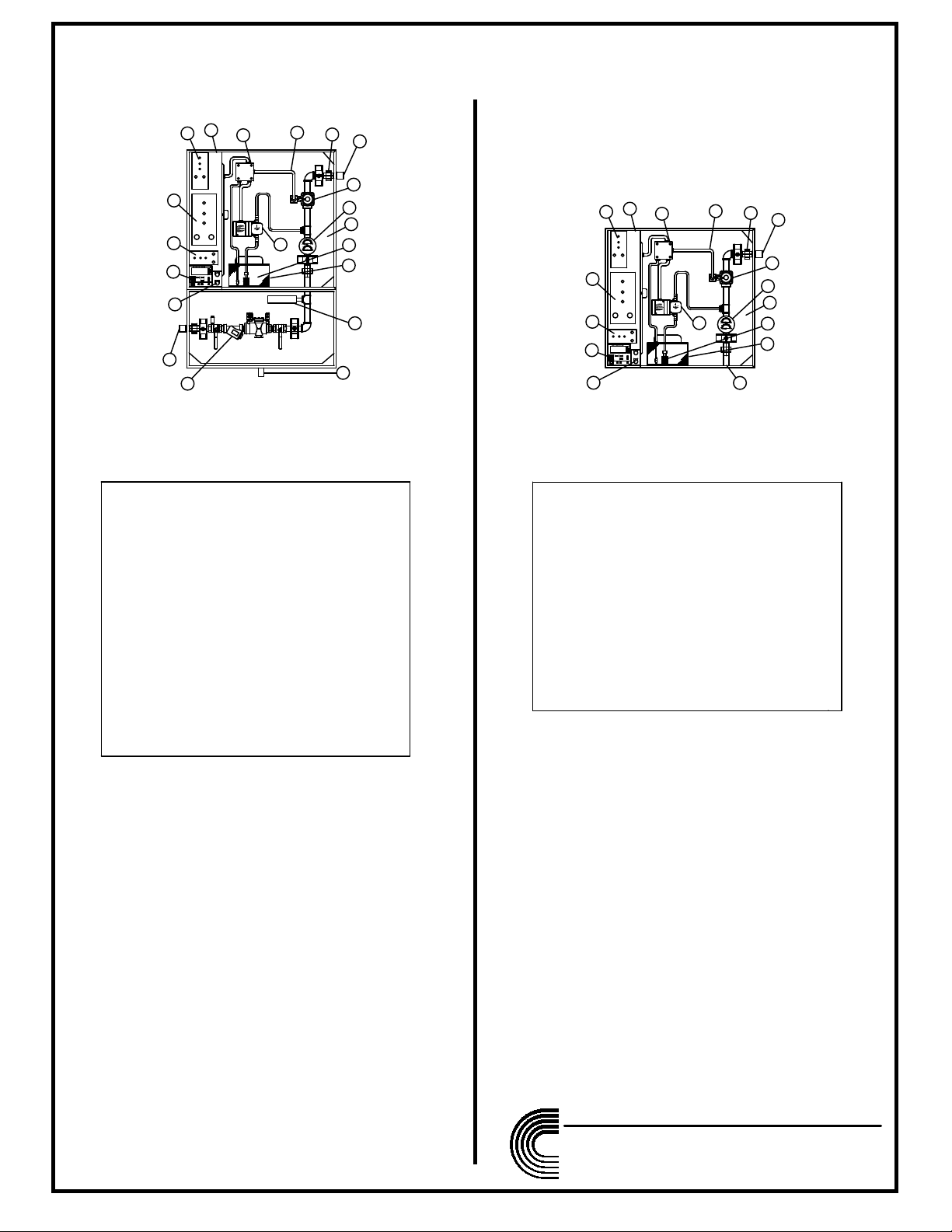
COMPONENT DETAILS (NON- SEQUENTIAL)
509 Sharptown Road P.O. Box 345
Bridgeport, NJ 08014-0345
Tel: 856-467-4222 Fax: 856-467-5511
internet: www.caddycorp.com
CADDY CORPORATION
All specifications subject to change without notice
01/08
LEGEND
1. UNION (TYPICAL)
2. WATER SOLENOID VALVES (S)
3. PRESSURE/TEMPERATURE GAUGE
4. DETERGENT RESERVOIR
5. DETERGENT LINE WITH FOOT VALVE
6. DETERGENT PUMP
7. WATERTIGHT FLEX CONDUIT (TYPICAL)
8. WATERTIGHT POWER DISTRIBUTION JUNCTION BOX
9. PLUMBING COMPARTMENT
10. ELECTRICAL COMPARTMENT
11. FIRE TEST STATION
12. PROGRAMMABLE TIME CLOCK (OPTIONAL)
13. PROGRAMMABLE LOGIC CONTROLLER
14. INTERNAL RELAY STRIP
15. FIELD WIRING TERMINAL STRIP
16. HOT WATER OUTLET
17. HOT WATER INLET
MODEL CPE-1.25-TC
LEGEND
1. UNION (TYPICAL)
2. WATER SOLENOID VALVES (S)
3. PRESSURE/TEMPERATURE GAUGE
4. DETERGENT RESERVOIR
5. BACKFLOW PREVENTER (RP DEVICE)
WITH 1/4 TURN SHUT OFF VALVE
6. DETERGENT LINE WITH FOOT VALVE
7. DETERGENT PUMP
8. WATERTIGHT FLEX CONDUIT (TYPICAL)
9. WATERTIGHT POWER DISTRIBUTION JUNCTION BOX
10. 1" "RP" DRAIN
11. PLUMBING COMPARTMENT
12. ELECTRICAL COMPARTMENT
13. FIRE TEST STATION
14. PROGRAMMABLE TIME CLOCK (OPTIONAL)
15. PROGRAMMABLE LOGIC CONTROLLER
16. INTERNAL RELAY STRIP
17. FIELD WIRING TERMINAL STRIP
18. HOT WATER INLET
19. HOT WATER OUTLET (TYPICAL)
20. WATER HAMMER
MODEL CPE-1.25-RP-TC
page 2 of 7
Page 4

54"
17 1/4"
END VIEW
36 1/4"
8"
22"
32"
10"
21
25
22
23
25
24
12:00
PLC.
RELAY STRIP
STRIP
TERMINAL
3
18
5
13
14
15
10
7
4
6
17
12
9
16
11
8
1
19
2
20
509 Sharptown Road P.O. Box 345
Bridgeport, NJ 08014-0345
Tel: 856-467-4222 Fax: 856-467-5511
internet: www.caddycorp.com
CADDY CORPORATION
All specifications subject to change without notice
01/08
Optional Features (Non-Sequential and
Sequential)
__Time Clock-- To include a 24 hour, 7 day solid state LCD
programmable time clock for automatic operation. Program
options to include starting and stopping the exhaust fan and
starting the wash cycle automatically at a pre-determined time of
day. Time clock to be equipped with an internal battery back-up to
hold the programmed time and programmed memory fuctions.
__Low Detergent Alarm-- To include a low detergent flow switch
to initiate a visual alarm when detergent drops below a pre-set
level in the reservoir.
__Continuous Cold Water Mist-- To include provisions for
continuous cold water mist for use over solid fuel burning cooking
equipment. Components of manifold to include shut-off valve,
solenoid valve, pressure requlator and pressure gauge.
__Remote Fire Switch-- To include a remote break-glass type fire
switch for installation at the nearest exit as indicated on the plans.
__Security Package-- To include a keyed latch to prevent
unauthorizedaddess inthe control panel.
and electrical compartments. The electrical compartment shall be
water tight to protect against direct hose spray. Electrical controls
shall include a programmable logic controller (PLC) for control of
the exhaust fan, wash cycle and internal fire protection system.
The face of the panel shall be equipped with system status
indicator lights which include "Fan On", "Wash On", and "Fire
Mode". An audio alarm to indicate "Fire Mode" is also standard.
Panel shall also be equipped with volt-free contacts to allow for
connection to a remote exhaust and supply fan motor control
center. Contacts are also provided to allow for interconnection
between the internal and system. Plumbing components to
include water shut-off valve, pressure/ temperature gauge,
normally closed water solenoid valve, detergent pump with
extended foot valve, detergent tank and ______ vacuum
breaker/check valve shipped loose for installation by the Plumbing
Contractor (standard), ____ built-in reduced pressure (RP)
principle device back flow preventor (optional). When specified
with an "RP" device as required by cold. All components shall be
pre-wired and pre-plumbed for field connection by applicable
trades. Control cabinet shall be U.L. listed.
LEGEND
1. UNION (TYPICAL)
2. WATER SOLENOID VALVES (S)
3. PRESSURE/TEMPERATURE GAUGE
4. DETERGENT RESERVOIR
5. BACKFLOW PREVENTER (RP DEVICE)
WITH 1/4 TURN SHUT OFF VALVE
6. DETERGENT LINE WITH FOOT VALVE
7. DETERGENT PUMP
8. WATERTIGHT FLEX CONDUIT (TYPICAL)
9. WATERTIGHT POWER DISTRIBUTION JUNCTION BOX
10. 1" "RP" DRAIN
11. PLUMBING COMPARTMENT
12. ELECTRICAL COMPARTMENT
13. FIRE TEST STATION
14. PROGRAMMABLE TIME CLOCK (OPTIONAL)
15. PROGRAMMABLE LOGIC CONTROLLER
16. INTERNAL RELAY STRIP
17. FIELD WIRING TERMINAL STRIP
18. HOT WATER INLET
19. HOT WATER OUTLET (TYPICAL)
20. WATER HAMMER
21. START FAN SWITCH
22. START WASH SWITCH
23. SYSTEM STATUS INDICATOR LIGHTS
24. SON ALERT AUDIBLE ALARM
25. RECESSED HANDLE FOR PLUMBING
COMPARTMENT ACCESS
MODEL CPE-S-4-1.25-RP-TC
COMPONENT DETAILS (SEQUENTIAL)
page 3 of 7
Page 5

7
12:00
PLC.
RELAY STRIPRELAY STRIP
TERMINAL
STRIP
P1
P3
P2
6
12:00
PLC.
RELAY STRIPRELAY STRIP
TERMINAL
STRIP
P1
P2
7
12:00
PLC.
RELAY STRIPRELAY STRIP
TERMINAL
STRIP
E1
E2
E3
E4
E5
E6
TYPICAL PLUMBING AND ELECTRICAL
INFORMATION
509 Sharptown Road P.O. Box 345
Bridgeport, NJ 08014-0345
Tel: 856-467-4222 Fax: 856-467-5511
internet: www.caddycorp.com
CADDY CORPORATION
All specifications subject to change without notice
01/08
PLUMBING REQUIREMENTS- "RP" TYPE
PLUMBING NOTES
PLUMBING REQUIREMENTS-NON "RP" TYPE
P1 __" Hot water connection to CPE
panel by plumbing contractor.
0LQLPXPZDWHUWHPS )
0D[LPXPZDWHUWHPS )
Operating pressure between 40-80 PSI.
P2 __" Hot water connection(s) from CPE
panel to hood connection(s)
by plumbing contractor.
P3 1" drain connection to fllor sink by
plumbing contrctor.
WATER CONSUMPTION
__ G.P.M. @ 40 P.S.I. 5 min. wash
cycle per 24 hr. period.
(SHOWN WITH DOOR REMOVED
FRONT ELEVATION)
PLUMBING NOTES
P1 __" Hot water connection to CPE
panel by plumbing contractor.
0LQLPXPZDWHUWHPS )
0D[LPXPZDWHUWHPS )
Operating pressure between 40-80 PSI.
P2 __" Hot water connection(s) from CPE
panel to hood connection(s)
by plumbing contractor.
WATER CONSUMPTION
__ G.P.M. @ 40 P.S.I. 5 min. wash
cycle per 24 hr. period.
NOTE: Vacuum breaker and check
valve assembly shipped loose for
installation by plumbing contractor.
(SHOWN WITH DOOR REMOVED
FRONT ELEVATION)
HOT WATER PIPE INLET SIZE CHART
Total Linear Feet
of Ventilator
3'-0" to 12'-0"
12'-0" to 22'-0"
22'-0" to 44'-0"
44'-0" to 60'-0"
NPT Size
3/4"
1"
1 1/4"
1 1/2"
IMPORTANT NOTE: The pipe inlet size for a sequential control panel is to be the
same size as the pipe size required for the largest wash group.
TYPICAL ELECTRICAL INFORMATION
E1 120/1/60 15A. (min.) service by electrical contractor.
E2* 4 wires from control panel to hood exhaust damper
control boxes by electrical contractor.
E3 2 wires from control panel to exhaust fan magnetic starter holding coil by
electrical contractor. Holding coil to be 120v /1 phase.
Supply fan to be wired in parallel with exhaust fan.
E4 2 wires from alarm terminal dry contacts (N.O. or N.C.) located in control
panel to building alarm system by alarm contractor or electrical contractor.
E5 2 wires from remote fire pull station (if required) to FS1 and FS2
terminals in control panel by electrical contractor.
E6 2 wires from Ansul micro switch (N.O. contacts) to Ansul 1 and Ansul 2
terminals in control panel by electrical contractor (if required).
*- 5 wire loop between hood damper controls only by electrical
contractor. See damper wiring control circuit diagram.
ELECTRICAL INFORMATION
page 4 of 7
Page 6

MIST VALVE FUSE
CR1-6
CR1
CR1
10 A
CR1-9
PLC 1 AND 2
NOTES:
CR2
CR2-9CR2-6
CR1-4CR1-7
CR2
CR2-7
CR3
CR3-6
CR3-3
CR3-4
CR3-7
CR3-9
CR3-9
CR2-4
DC +
PLC INPUT 9
14
CR4
13
CR3-1
CR3-7
B. EXHAUST AND SUPPLY FAN RELAYS ARE
RATED AT 10 AMP (1/3 HP) @ 120 VAC.
A. PROVIDE 120 VOLT, 60 HZ, 15 AMP SERVICE
TO THE PANEL , FUSED SEPERATELY. POWER
CR4 DAMPER SWITCH (THERMOSTAT) - 120V IN
MUST BE AVAILABLE 24 HOURS.
CR6 DETERGENT PUMP
CR2 SUPPLY FAN - DPDT
CR1 EXHAUST FAN - DPDT
C. RELAY ASSIGNMENTS
CR5 OPT. PULL STATION - SPDT
CR3 ALARM / TROUBLE SIGNAL - DPDT
1. AC INPUT
2. AC GROUND (GROUND)
3. AC NEUTRAL (INPUT)
4. EXHAUST FAN HOT (E.FAN L)
5. EXHAUST FAN NEUTRAL (E.FAN N)
NOTE # 5
6. EXHAUST FAN NO (E.FAN NO)
7. EXHAUST FAN NO (E.FAN NO)
8. SUPPLY FAN HOT (S.FAN L)
9. SUPPLY FAN NUE (S.FAN N)
10. SUPPLY FAN NO (S.FAN NO)
11. SUPPLY FAN NO (S.FAN NO)
12. ALARM NO (ALM-OPN)
13. ALARM COM (ALM-COM)
14. ALARM NC (ALM-CLO)
15. FIRE SYS NO (FI-OPN)
16. FIRE SYS COM (FI-COM)
17. FIRE SYS NC (FI-CLO)
18. PULL STATION (FS1)
19. PULL STATION (FS2)
20. ANSUL (ANSUL 1)
21. ANSUL (ANSUL2)
22. EX. FAN OPT. JMPR (EF DIS)
23. EX. FAN OPT. JMPR (EF DIS)
24. DAMPER SW. (LAST F)
E1
E1
E1
E3
E3
E3
E3
E4
E2
26. FIRST A
H
G
N
E2
SEE NOTE #1
SEE NOTE #1
SEE NOTE #4
NOTE # 6
NOTE # 2
13
CR5
14
25. DAMPER SW. (C INPUT)
27. B-DAMPER TEST
E2
E2
SEE NOTE #3
E5
E6
120 VOLT A.C. 1 PHASE 60 HZ. 15 AMPS.
SERVICE BY ELECTRICAL CONTRACTOR
AC LOAD
DISTRIBUTION BLOCK
AC NEUTRAL
DISTRIBUTION BLOCK
509 Sharptown Road P.O. Box 345
Bridgeport, NJ 08014-0345
Tel: 856-467-4222 Fax: 856-467-5511
internet: www.caddycorp.com
CADDY CORPORATION
All specifications subject to change without notice
01/08
1. Exhaust fan N/O and supply fan N/O terminals are voltage free
N/O sets of contacts for use with a remote motor control station.
SEQUENCE OF OPERATIONS
"FAN ON" - contacts close to start exhaust and supply fans.
"Wash on" - Contacts open to stop exhaust and supply fans.
"External fire" (fire switch pulled, fire system discharged)
Exhaust fan N/O contacts close to start exhaust fan.
Supply fan N/O contacts open to stop supply fan.
"Internal fire" ( ventilator thermostat closure) contacts open to
stop exhaust and supply fan.
2. Unit is shipped with a factory installed jumper across exhaust fan
disable terminals. With jumper installed "external fire" condition will
result in exhaust and supply fan shutdown. Removal of jumper will
cause exhaust fan to start, if off, or remain running if on, and supply
fan to stop during external fire condition.
WIRING DIAGRAM AND NOTES
3. Alarm com,. alarm N/C, alarm N/O-voltage free contacts for
connection to building alarm system. Contacts transfer during
either internal or external fire mode.
4. Alarm com,. alarm N/C, alarm N/O-voltage free contacts for
connection to building alarm system. Contacts transfer during
either internal or external fire mode. (Optional)
5. Factory installed jumper. Removed jumper and install N/C
remote fire switch if required. Pulling switch will initiate external
fire mode.
6. Factory installed jumper. Removed jumper and connect to N/C
micro switch in Ansul, Kidde, or Pyrochem system. Fire system
discharge will initiate external fire mode.
page 5 of 7
Page 7

BY CADDY AIR SYSTEMS
BY ELECTRICAL CONTRACTOR
ACKNOWLEDGED ON OUR STANDARD FORM.
FABRICATION. ANY SUBSEQUENT CHANGES REQUIRED MUST BE SUBMITTED TO US IN WRITING AND
WILL BE CONSTRUCTED IN ACCORDANCE WITH OUR DRAWING(S) WHICH MUST BE APPROVED PRIOR TO
ALL WIRING AND PLUMBING AT THE JOB SITE IS THE RESPONSIBILITY OF OTHERS. EQUIPMENT
OUR ATTENTION AND ARE EXPRESSLY INCLUDED IN OUR WRITTEN QUOTATION.
TO CADDY CORPORATION OF AMERICA, UNLESS THESE CONDITIONS WERE PREVIOUSLY BROUGHT TO
REGIONAL OR LOCAL CODE REQUIREMENTS IS TO BE DONE BY OTHERS AND WITHOUT BACK CHARGE
ANY FIELD WORK RELATING TO THE MODIFICATION OF ELECTRIC OR PLUMBING SYSTEMS,TO MEET
CODES THAT ADD OR DEVIATE FROM THE ACCEPTED STANDARDS OF THE ABOVE AGENCIES.
DOES NOT ACCEPT ANY RESPONSIBILITY FOR THE REQUIREMENTS OF ANY REGIONAL AND/OR LOCAL
THE LATEST EDITION OF THE NATIONAL ELECTRICAL CODE(NEC). CADDY CORPORATION OF AMERICA
STANDARDS PUBLISHED BY THE UNDERWRITER'S LABORATORIES,INC. INSOFAR AS APPLICABLE, AND
ELECTRICAL WORK DONE BY CADDY CORPORATION OF AMERICA IS EXECUTED IN COMPLIANCE WITH
GENERAL CONTRACT CONDITIONS
BE 115 VOLTS.
HOWEVER, COIL MUST
MAKE OF STARTER
VARY ACCORDING TO
WIRING DIAGRAM MAY
MAGNETIC STARTER
MOTOR STARTER
C
E3
CUSTOMER
SUPPLY
MOTOR STARTER
MAGNETIC STARTER
WIRING DIAGRAM MAY
VARY ACCORDING TO
MAKE OF STARTER
HOWEVER, COIL MUST
BE 115 VOLTS.
EFM
C
SUPPLY
CUSTOMER
E3
1. AC INPUT
2. AC GROUND (GROUND)
3. AC NEUTRAL (INPUT)
4. EXHAUST FAN HOT (E.FAN L)
5. EXHAUST FAN NEUTRAL (E.FAN N)
NOTE # 5
6. EXHAUST FAN NO (E.FAN NO)
7. EXHAUST FAN NO (E.FAN NO)
8. SUPPLY FAN HOT (S.FAN L)
9. SUPPLY FAN NUE (S.FAN N)
10. SUPPLY FAN NO (S.FAN NO)
11. SUPPLY FAN NO (S.FAN NO)
12. ALARM NO (ALM-OPN)
13. ALARM COM (ALM-COM)
14. ALARM NC (ALM-CLO)
15. FIRE SYS NO (FI-OPN)
16. FIRE SYS COM (FI-COM)
17. FIRE SYS NC (FI-CLO)
18. PULL STATION (FS1)
19. PULL STATION (FS2)
20. ANSUL (ANSUL 1)
21. ANSUL (ANSUL2)
22. EX. FAN OPT. JMPR (EF DIS)
23. EX. FAN OPT. JMPR (EF DIS)
24. DAMPER SW. (LAST F)
E1
E1
E1
E3
E3
E3
E3
E4
E2
SFM
26. FIRST A
H
G
N
120 VOLT A.C. 1 PHASE
60 HZ. 15 AMPS. SERVICE BY
ELECTRICAL CONTRACTOR
E2
EXHAUST FAN SUPPLY FAN
SEE NOTE #1
SEE NOTE #1
SEE NOTE #3
NOTE # 6
NOTE # 2
N/C MIRCOSWITCH
IN SURFACE
PROTECTION
SYSTEM
(SEE NOTE #6)
25. DAMPER SW. (C INPUT)
27. B-DAMPER TEST
E2
E2
MIST VALVE FUSE
CR1-6
CR1
CR1
10 A
CR1-9
PLC 1 AND 2
NOTES:
CR2
CR2-9CR2-6
CR1-4CR1-7
CR2
CR2-7
CR3
CR3-6
CR3-3
CR3-4
CR3-7
CR3-9
CR3-9
CR2-4
DC +
PLC INPUT 9
14
CR4
13
CR3-1
CR3-7
B. EXHAUST AND SUPPLY FAN RELAYS ARE
RATED AT 10 AMP (1/3 HP) @ 120 VAC.
A. PROVIDE 120 VOLT, 60 HZ, 15 AMP SERVICE
TO THE PANEL , FUSED SEPERATELY. POWER
CR4 DAMPER SWITCH (THERMOSTAT) - 120V IN
AC NEUTRAL DISTRIBUTION BLOCK
MUST BE AVAILABLE 24 HOURS.
CR6 DETERGENT PUMP
CR2 SUPPLY FAN - DPDT
CR1 EXHAUST FAN - DPDT
C. RELAY ASSIGNMENTS
CR5 OPT. PULL STATION - SPDT
CR3 ALARM / TROUBLE SIGNAL - DPDT
AC LOAD DISTRIBUTION BLOCK
13
CR5
14
509 Sharptown Road P.O. Box 345
Bridgeport, NJ 08014-0345
Tel: 856-467-4222 Fax: 856-467-5511
internet: www.caddycorp.com
CADDY CORPORATION
page 6 of 7
Page 8

ITEM #
ITEM #
ITEM #
A1
B1
C
C1
1
7
D1
4
E1
F1
DAMPER CONTROL
TERMINALS
FIFTH WIRE LOOP BETWEEN ALL DAMPER
ASSEMBLIES BY ELECTRICAL CONTRACTOR.
NOTES:
1. Exhaust fan N/O and supply fan N/O terminals are voltage free
N/O sets of contacts for use with a remote motor control station.
SEQUENCE OF OPERATIONS
"FAN ON" - contacts close to start exhaust and supply fans.
"Wash on" - Contacts open to stop exhaust and supply fans.
"External fire" (fire switch pulled, fire system discharged)
Exhaust fan N/O contacts close to start exhaust fan.
Supply fan N/O contacts open to stop supply fan.
"Internal fire" ( ventilator thermostat closure) contacts open to
stop exhaust and supply fan.
2. Unit is shipped with a factory installed jumper across exhaust fan
disable terminals. With jumper installed "external fire" condition will
result in exhaust and supply fan shutdown. Removal of jumper will
cause exhaust fan to start, if off, or remain running if on, and supply
fan to stop during external fire condition.
3. Alarm com,. alarm N/C, alarm N/O-voltage free contacts for
connection to building alarm system. Contacts transfer during
either internal or external fire mode.
4. Alarm com,. alarm N/C, alarm N/O-voltage free contacts for
connection to building alarm system. Contacts transfer during
either internal or external fire mode. (Optional)
5. Factory installed jumper. Removed jumper and install N/C
remote fire switch if required. Pulling switch will initiate external
fire mode.
6. Factory installed jumper. Removed jumper and connect to N/C
micro switch in Ansul, Kidde, or Pyrochem system. Fire system
discharge will initiate external fire mode.
A2
B2
C
C2
7
D2
E2
F2
DAMPER CONTROL
TERMINALS
1
4
A3
B3
C
C3
7
D3
E3
F3
DAMPER CONTROL
TERMINALS
1
4
THE CADDY VENTILATOR TESTING,
LISTING AND APPROVAL REFERENCES:
NATIONAL FIRE PROTECTION ASSOCIATION
In Accordance with Recommendation of National Fire
Protection Association's NFPA NO. 96 "Vapor Removal From
Cooking Equipment"
NATIONAL SANITATION FOUNDATION
Standard #2 - "Food Service Equipment"
UNDERWRITERS LABORATORIES, INC
Tested under standard U.L. 710 "Exhaust Hoods for
Commercial Cooking Equipment". U.L. Listed under file number
MH8215 and MH12264
UNIFORM MECHANICAL CODE
Section 507 - Commercial Kitchen Hoods and Kitchen
Ventilation Systems
THE BOCA NATIONAL MECHANICAL CODE
Chapter 5 - Kitchen Exhaust Equipment
STANDARD MECHANICAL CODE (SBCCI)
Section 504 - Commercial Hoods
UNIFORM BUILDING CODE (ICBO)
INTERNATIONAL MECHANICAL CODE (IMC)
REV DATE BY
REVISIONS
REMARKS
P.O. BOX 345 BRIDGEPORT NJ 08014
Tel:(856) 467-4222 Fax:(856) 467-5511
R
FILE NO. MH82155P
AirSystems
509 SHARPTOWN ROAD
EQUIPMENT SCHEDULE
MASTER WIRING DIAGRAM FOR
CPE AND CPE-RP WATER WASH
CONTROL PANELS.
DATE SCALE
DR BY
DRA
APP'D BY
AS NOTED
DWG#
SHT
OF
1
1
CADDY CORPORATION
509 Sharptown Road P.O. Box 345
Bridgeport, NJ 08014-0345
Tel: 856-467-4222 Fax: 856-467-5511
internet: www.caddycorp.com
page 7 of 7
 Loading...