

Page 1

#
7g8;2'
Audio Mixing Console
-056#..#6+10#n#95'4#1#07#.
Page 2

CADAC Electronics
One New Street
Luton
Bedfordshire
LU1 5DX
England
Tel +44 (0) 1582 404 202
Fax +44 (0) 1582 412 799
email: info@cadac-s ound.com
While every effort has been taken to ensure the accuracy of the contents in this manual, CADAC Audio Mixing Consoles are being subject to
conti nuous development, hen c e the information in this manual may no t reflect latest prod uct updates.
© 2005 CADAC Electronics plc
Page 3

Table of Cont ents iii
7DEOH#RI#&RQWHQWV
,QWURGXFWLRQ11111111111111111111111111111111111111111111111111111111111111#Y
4 6\VWHP#RYHUYLHZ11111111111111111111111111111111111111111111111111 #404
1.1 The console .................... ............... .... ............... .... .... ............... .... . 1-1
1.2 The frame . ... .... .... ............... .... ............... .... .... ............... .... ............. 1-1
1.3 Power supply ......................... .... .... ............... .... ............... .... .... .....1-2
1.4 The modules ....... .... .... .... ............... .... ... ................ .... ............... .... . 1-2
5 &RQQHFWLRQV#DQG#VHWXS 1111111111111111111111111111111111111111 #504
2.1 Setting up the console .................................................................. 2-1
2.2 Frame rear connections................................................................ 2-1
2.3 Connectin g pow er supp li es.... .... ............... .... .... ............... .... ......... 2-2
2.4 Connecting the console frames .................................................... 2-5
6 +RZ#WR#XVH#WKH#607\SH11111111111111111111111111111111111111111 #604
3.1 Assigning channels to VCA Masters............................................. 3-1
3.2 Using the sends ............................................................................3-1
3.3 Solo a channel (Des tru ct ive)................. .... .... ............... .... ............. 3-2
3.4 Using the PFL ...............................................................................3-2
7 0RQR#LQSXW#PRGXOH#;74411111111111111111111111111111111111111 #704
4.1 Front panel - mono input channel module 8411 ........................... 4-2
4.2 Rear panel - mono input channel module 8411............................ 4-9
8 6WHUHR#LQSXW#PRGXOH#;745111111111111111111111111111111111111 #804
5.1 Front panel stere o inp ut modul e 8412 .. .... .... .... ............... .... .... .....5-2
5.2 Rear panel stereo input channel module 8412 .............................5-9
9 *URXS/#PDWUL[#DQG#DX[#RXWSXW
0#VWHUHR#;746/#PRQR#;748 111111111111111111111111111111111111 #904
6.1 Front p anel group, matr ix and au xiliary output:
Stereo 8413 - Mono 8415 ............................................................. 6-2
6.2 Rear panel group, matrix and auxiliary output:
Stereo 8413 - Mono 8415 ............................................................. 6-8
: 6WHUHR#RXWSXW/#&RPPV/#2VF#DQG#
7DONEDFN#PRGXOH#;74711111111111111111111111111111111111111111 #:04
7.1 Front panel Stereo output, Comms, Osc and
Talkback module 8414.................................................................. 7-2
7.2 Rear panel Stereo outp ut, Comms, Osc an d
Talkback module 8414................................................................ 7-10
$SSHQGLFHV11111111111111111111111111111111111111111111111111111111#$330,
,QGH[11111111111111111111111111111111111111111111111111111111111111#,1'(;0,
7HFKQLFDO#VSHFLILFDWLRQV 1111111111111111111111111111111 #63(&0,
*ORVVDU\ 111111111111111111111111111111111111111111111111 #*/266$5<0,
Revision S2005-6 S-Type
Page 4

iv Table of Cont ents
S-Type Revision S2005-6
Page 5

Introduction v
,QWURGXFWL RQ
Welcome to the CADAC S-Type compact frame mixing console. The S-Type is the
result of extens ive market research, reflecting us ers’ need for a high quality, mode rately sized console with state of the art design and perfo rmance.
CADAC have been synonymous with superior audio quality, adaptability in use and
roc k solid build for over three decades. The S-Type, created from the same lineage,
is equally suitable for the hard life on the road as well as the perhaps more peaceful
existence in an industrial, corporate or theatre setting.
As is the case with the rest of the CADAC line-up, the S-Type provides complete flexibility that allows for any configuration the user wishes to apply, whilst providing the
reliability that is paramount to t he production of a show, concert or corpor ate event.
The audio legacy of pre vious CADA C mixing consoles is ref lected in the design of
the new S-Type. For those of you familiar with the legendary J and F-Types, it will
come as no surprise to find the same renowned mic amplifier , VCA and fully parametric 4-band equaliser and respected audio architecture. The S-Type mirrors the
same attention to quality and detail that have made the CADAC name the ultimate
choice for the discerning pr ofessional.
Ergonomics has been placed high on the design brief. Every function switch is supported by an indicator LED for full visual feedback in low light conditions.
All internal busses are fully balanced and use very low value mix resistors to provide
both low noise and exceptionally low crosstalk.
Output sections are fully bala nced and compensated* to provide low noise with the
power to drive long lines - again with very good CMRR.
(*Compensated means that if one leg of the balanced circuit goes short circuit, there
will be no 6dB drop in level.)
All ar eas of circuitry are extensively power decoupled. This prevents broadband
noise from being transmitted into adjacent circuits through the pow er rails. Extensive
decoupling of the signal paths minimizes the low frequencies phase shift.
The S-Type frame is available in 3 sizes - 17, 25 or 33-way. In combination, these
frame sizes cater for the most common console requirements, and may, of course be
configured to meet your sp ecific needs. A standar d feature is the ability to c onnect
frames together via the external frame bus connector.
Fina lly, it goes without say ing, that in the CADAC tradition the sound quality of the SType is in a class of its own.
Revision S 2005-6 S-Type
Page 6

vi Introduction
S-Type Revision S2005-6
Page 7

Syste m ov erv iew 1-1
4 6\VWHP#RYHUYLHZ
414 7KH#FRQVROH
Mixing consoles comprise of a number of input channels and output groups with
associated faders, monitoring and control functions. When module positions are
fixed in relation to the frame structure, various operational compromises may occur.
The S-Type console system al lows for any module to be plac ed into any frame position and to change the number of frames associated with the system to increase or
decr ease the number of input channels and output gr oups to meet the needs of a
particular project. Please be aware that the console needs to be turned off before
any reconfiguration can be carried out.
There are three S-Type frames offering either 17, 25 or 33 module positions (slots).
Each frame has provi s ion for main and backup power suppl y inputs and any two
adjacent frames have full audio bus and control function interconnection via 3 x 37way D-type connectors for multiple frame connectivity.
The S-Type frame provides a total of 20 ba lanced busses - 8 sub-group bu s ses, 1
dedicated stereo bus, 6 mono busses, 2 stereo auxiliary busses, 8 matrix busses
and PFL. A further 8 matrix send busses and a stereo listen bus are provided.
Standard channel VCA faders can access up to 8 VCA master faders.
The S-Type is designed to comply with following standards: EN55103-1:1997,
EN55103-2:1997, EN60065:1998.
415 7KH#IUDPH
The S-Type frame is constructed from 1.6mm Zintec , fixed to 4mm aluminium end
profiles. This constructi on allo ws multiple frames to be positioned so that modules
are almost adjacent. Internal au dio bussing is balanced and uses ribbon cables.
The rear panel of the frame contains outputs for the stereo master, plus insert send s
and returns for the same. Two PSU input connectors are prov ided - one for ma in and
fo r the backup supply. Power rail LEDs are provided for each PSU input. The S -Type
frame also incorporates two Littlite connectors in addition to fan and Littlite fuses. A
headphone jack is provided on the front of the frame.
The three standard frame sizes enable a vast variety of configurations to be
achieved. For example:
17 slot frame: 8 mono input channels, 8 output g roups and 1 stereo master
25 slot frame: 16 mono in put channels, 8 output groups and 1 stere o master
33 slot frame: 24 mono in put channels, 8 output groups and 1 stere o master
Note: The choice is yours, a 33 slot frame could be configured as follows:
20 mono input channels, 8 stereo input channels, 4 output groups and 1 stereo master.
By bu s linking multiple frames together, larger co nfigurations can be achieved. For
example:
Two 25 slot frames:
40 mono input modules, 1 stereo input module, 8 output groups and 1 stereo master.
One 25 slot fr ame and one 33 slot frame:
48 mono input modules, 1 stereo input module, 8 output groups and 1 stereo master.
Three 25 slot frames:
56 mono input modules, 10 stereo input modules, 8 output groups and 1 stereo master.
The module electronics are cooled via internally mounted silent fans.
Revision S2005-6 S-Type
Page 8

1-2 System overview
416 3RZHU#VXSSO\
The main power supply for the S-Type is integrated into an external 2U rack mount
unit with the option of a backup PSU. See sub-section 2.3.1 Power sup ply descrip-
tion.
417 7KH#PRGXOHV
41714 ,QSXW#FKDQQHO#PRGXOHV/#;744#0RQR#)#;745#VWHUHR
Mono and stereo input modules are available for the S-Type. Both modules provide
balanced insert sends and returns; four band parametric EQ - selectable pre or post
insert and high-pass filter; balanced direct output - selectable pre/post fader, or post
MIC pre-amplifier,
Each module incorporates a VCA channel fader, VCA Master assignment swit ches
and a full range level meter (with dual input meters on the stereo input module).
Full details of the module functions can be found in chapters 4 Mono input module
8411 and 5 Stereo input module 8412. Also, see Appendices .
41715 * URXS/#0DWUL[#DQG#$X[LOLDU\#PDVWHU#PRGXOHV#;746#VWHUHR#
)#;748#PRQR
Each of t he outp ut mod ul es pr o vi de one Su b-G ro up outp ut , an 8-w ay level co nt rol l ed
send to Matrix, Matrix Master, and an Auxiliary Master output.
Up to 8 modules may be specified per cons ole (maximum configuration b eing two
8413 and six 8415 modules) and each module can be placed anywhere in the multiframe console structure (they do not need to be placed adjacent to each other, or
even in the same frame). Visual monit o ring of output levels is p rovided on full range
LED- meters, PFL facilitie s on the outputs are provided, as are balanced insert points
on the Sub-Group and Matrix outputs.
Full details of the module function can be fo und in chapter 6 G roup, Matr ix and Auxiliary Ma s t er mo dules, 8413 stereo and 84 15 mono.
41716 6WHUHR#RXWSXW/#&RPPV/#2VF#)#7DONEDFN##PRGXOH#;747
The Stereo Master module is fitted with a 100mm Penny & Giles fader, balanced
insert send and returns and balanced outputs (these are fou nd on the rear of the
frame). The Stereo Master module also provides metering for both the main stereo
mix and listen busses, while the stereo mix bus can also be rout ed to the Matrix
sends in true stereo or summe d mono via 4 dual concentric potentiometers.
Provision is made to inject an unbalanced stereo input source into the main stereo
bus.
The S-Type console offers the operator PFL monitoring functionality. If the source
signal is mono it will appear in mono a nd if the signal is in stereo it will appear in stereo.
PFL appears at the Listen output, which provides stereo meters, level control via a
potentiometer and mute control. The Listen output busses appear on balanced
XLR's on the re ar of the module. PFL is also routed to the Headphones level control
and mute, the output of which is provid ed via a jack socket on the front of the frame
and is capable of driving 8 ohm loads.
The module also incorporates an oscillator with selectable frequencies at 100Hz,
1kHz and 10kHz. This is then routed via a level control to either the channels or the
groups.
S-Type Revision S2005-6
Page 9

Syste m ov erv iew 1-3
Littlites can be turned on and dimmed from this module.
The module also provides a talkback microphone input with gai n control, HPF and
phantom power. The signal can be routed to all 8 sub-groups and auxiliaries. The
output can be muted, which can then be over-ridden via the talkback button.
Check Mute and Mute All functions are located towards the top of the panel.
Full details of the module functions are discussed in chapter 7 Stereo ou tput,
Comms, Osc and Talkba ck module 8414.
Full details of the module functions are discussed in chapter 7 Stereo output,
Comms, Osc and Talkba ck module 8414.
Revision S2005-6 S-Type
Page 10

1-4 System overview
S-Type Revision S2005-6
Page 11

Connec t i on s and setup 2-1
5 &RQQHFWLRQV#DQG#VHWXS
514 6HWWLQJ#XS#WKH#F RQVR OH
The S-Type console is shipped in a flight-case to help protect it against any possible
damage during transit. The following describes how to set up the S-Type:
1. If the console flight case is to be mounted on the CADAC PSU case, then first
remove the PSU’s case’s front and rear cover . Note that if using a 2U drawer
case, there is only a front cover. Both types of cases have wheels fitted with
brakes at the front.
2. Using suitable manpower, place the console flight case on the 2U PSU or dr awers case . Mak e sure th at it is safely positi oned . Ot he rw is e po sit io n t he fl ig ht ca se
on a stu rdy surface.
3. Unlock the latches and remove the front section of the console flight case to
reveal the console armrest.
4. Unlock the remaining latches and r emove the upper section by lifting it clear of
the console.
5. If using multiple fram es, then make sure that they are all located in the appropriate positions, all wheels are locked and start cabling the frames together.
515 )UDPH#UHDU#FRQQHFWLRQV
The connections on the S-Type console rear fr ame include the following:
1. Frame to frame bus connections
2. Littlite connection
3. Stereo output Left
4. Stereo ou tput Right
5. PSU 1
6. PSU 2
7. Littlite fuse 1A
8. Fans fuse 1.5A
9. Frame 0V terminals
10. Send > Insert Sen d (stereo mix bus)
11. Return > Insert Return (stereo mix bus)
1
23
4
5678
21
91011
FIG 2-1. Frame rear pa nel
Revision S2005-6 S-Type
10 11
9
Page 12

2-2 Connections and setup
516 &RQQHFWLQJ#SRZHU#VXSSOLHV
51614 3RZHU#VXSSO\#GHVFULSWLRQ
The S-Typ e console is suppl ied with the model 8500 Power Supply Unit. Each 2U x
19” rack mount power unit supplies all 4 voltage required by the S-type console. If
more than one frame is to be used, then the 8400 Power Supply Unit may be used.
Cadac consoles are designed to allow th e use of two in dependent pow er supply systems in a redundant conf iguration - main and back-up. Both power supply units are
used to power the console system, so that under normal c onditions, the load is
shar ed equal ly between the main and back-up PSU. If a fault occurs in one of the
power units (causing it to shut down), the remaining power unit will power the console.
Designate one power supply unit as “PSU 1” and the other as “PSU 2”. PSU 1 and
PSU 2 sh ould be connected to the same phase on the same ‘spur’, wherever possible . In situations where it is necessary to provide a separate “feed” t o each PSU system, m ake sure the cable lengths are the same. This is to minimize any induced AC
power input noise by ensuring that the ‘EARTH IMPEDANCE’ is the same for both
PSU-systems.
1#/
The AC input connectors on each po wer supply have three conductors: LIVE
(brown), NEUTRAL (blue) and EARTH (green/yellow). For safety and electromagnetic compatibility considerations, it is essential tha t the EARTH conductor i s connected on all PSUs and the AC supply has an earth conductor that has a continuous
circuit to the ‘zero-signal reference potential’ point in the building. The ZSRP point in
a building is usually found near the place where the AC mains supply enters the
building (often referred to as the MAIN GROUND REFERENCE EARTH ELECTRODE SYSTEM). The basic concept for correct AC mains wiring distribution is
shown in figure 2-2. If yo u need further information about this complex subject,
please refer to “Grounding systems and their implementation” by Charles Atkinson
and Philip Giddins published in the AES Journal vol 43, No 6 - June 1995.
The g rounding scheme in CADAC consoles is designed to meet the rigorous EEC
Elec tromagnetic Compatibility require m ents (EMC directive - 1996). Any RF noise
induced in the console f rame(s) is directed to the loca l ZSRP, which is the metalwork
of the power supply units. In order to take full advantage ‘RF no ise immunity’ capability of the CADAC system, PSU AC mains ca bles and the AC mains supply EARTH
conductor must be connected correctly .
$5($#%5$1&+#3$1(/
-
-
/
1
(
/
1
(
$5($#%5$1&+#3$1(/
*1'#%$5
0$,1#*5281'#5()(5(1 &(#($57+#(/(&752'(#6<67(0
$5($#%5$1&+#3$1(/
*1'#%$5
-
-
/
1
(
/
1
(
FIG 2-2 . AC mains g rounding diagram (single phase 200-240V)
S-Type Revision S2005-6
Page 13
Connec t i on s and setup 2-3
51615 $&#SRZHU#UHTXLUHPHQWV
CADAC 8500 power supply units are desi gned to run from a minimum of 100V u p to
a maximum 250V, 50/60Hz.
The 85 00 is rated at +13V@15A, ±18V@11A and 48V@0.5A. Th is is sufficient to
supply power to one frame. In the case of more than frame, each frame can be powered b y a p ai r of 85 00 P o w er Sup pl y Uni t s (on e ma i n an d one f o r ba c k- up pu rpos es ).
Alternatively, 8400 Power Supply Units may be used, however please contact your
local distributor, or CADAC directly before any connections are made.
The AC input is connected to the PSU via a 3-core cable, CMA reference 3183TQ BASEC approved.
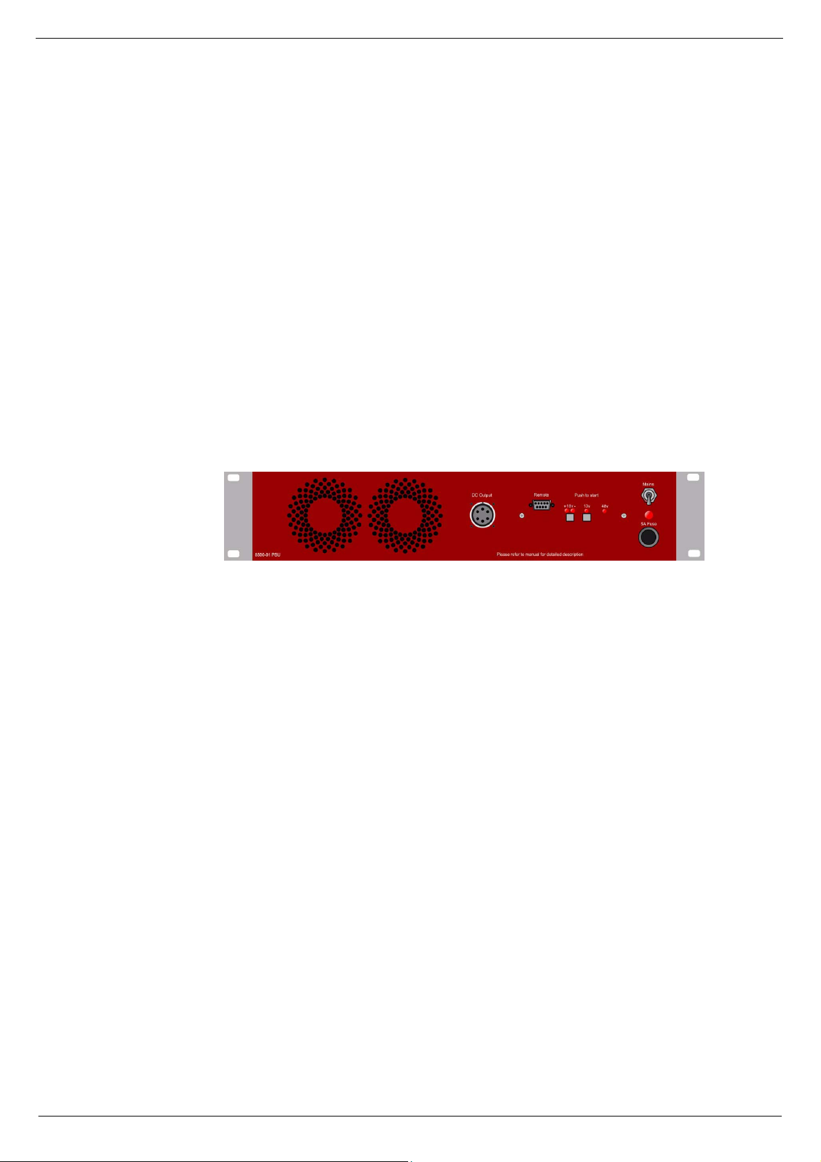
51616 ;833#6ZLWFK0PRGH#SRZHU#VXSSO\#XQLW
The 8500 is based on a Excelsys power block, rated at +13V@15A, ±18V@11A and
+48V@0.5A, with additional circuitry as shown in the accompanying draw ing set.
The 2U power supplies are suit able for rack-mounting or flight cases, and are connected via a shielded multi-core cable with 6 pole m ilitary circular bayonet at each
end. Each console may be powe red fro m two independen t powe r supply systems,
operating simultaneously for continuous redundant operation.
FIG 2-3. 8500 power sup ply unit
Revision S2005-6 S-Type
Page 14

2-4 Connections and setup
51617 5HPRWH#VWDUW#RI#WKH#368
Each 8500 switc h-mode power supply provides the f ollowing ou tputs: 13V, ±18V and
48V. Each PSU is fitted with a front panel mounted 9-way ‘D-type’ connector labelled
“Connections for Remote Start”. If a remote start facility is used, Power Failure and
Over-temperature LEDs may also be fitte d with the remote start switches if required.
Fig 2-5 shows the circuit for starting up a ‘syst em’ with a single switch. This has
proved to be the most popular method of connecting the remote start facility. This circuit can easily be extended to pr ovide a single switch for all PSUs if req u ired. If multipl e switches are to be used, see fig 2-4.
NOTE:
The remote start switch must be of a ‘momentary’ type . Y ou can use 3 separate
■■■■
single pole switches for each power supply to turn on 13V, ±18V and 48V outputs of
the PSUs alternatively use one single pole for the whole lot.
The remote switch(es) must be mounted on a metal panel.
■■■■
Use shielded cable for the remote switch wiring.
■■■■
The 9-way D-type free plug must have a conductive shell. This is to ensure that
■■■■
the cable shield connects directly to the PSU unit chassis.
Connect the cable shield to the metal panel where the remote s tart switch(es)
■■■■
are mounted.
FIG 2-4 . Re mo te st a rt wit h mul t ip le s w itch es
FIG 2-5. Remote start with a single switch
S-Type Revision S2005-6
Page 15

Connec t i on s and setup 2-5
51618 5HSODFLQ J#D#SRZHU#VXSSO\#XQLW
If replacing a power supply unit is required, please note the following:
The work should only be carried out by a suitably qualified electrician.
■■■■
Make sure that the po wer supply system’s power switches are in the OFF posi-
■■■■
tion and the unit is disconnected from t he mains.
Observe the correct polarity when connecting the new PSU.
■■■■
Note that a console must never have one voltage with out the other, for example
■■■■
+18V must never be fed into the console without -18V.
When switching the power supply back ON after replacement has taken place, make
sure that both LEDs on the front of the PSU-system come on. If only one LED comes
on, let go o f the O N pu sh -b ut ton imm edi a tely. Failure to do so ma y le ad to fi re h aza rd
and major damage to the console.
517 &RQQHFWLQ J #WKH#FRQVR OH#IUDPHV
51714 )UDPH#WR#IUDPH#EXV#FDEOHV
Frame 0V terminal
FIG 2-6. Audio Bus connections.
51715 )UDPH#JURXQG#FRQQHFWLRQ
When linking frames, plug the frame bus cable as shown in the diagram below:
Frame to frame bus
connections
Also, see Appendices.
Connect the frame-to-frame grounding cable. See figure 2-6 above for the location of
the frame 0V terminals.
Frame 0V terminal
Revision S2005-6 S-Type
Page 16

2-6 Connections and setup
S-Type Revision S2005-6
Page 17

How to use the S-Type 3-1
6 +RZ#WR#XVH#WKH#607\SH
This se ction of the manual provides inst ructions and information on how to use the
S-Type. The flexibility of the S-Type allows the operator to achieve the same result in
several ways. In this section you will learn how to perform certain procedures t o
achieve a desire d result. This does not mean, howe ver, that the same outcome cannot be achieved by taking a different route.
So to assist you in the most efficient way to becom e familiar with t he S-Type, pl ease
start with the instructions given. As you build up experience, you may well find that
alternative ways are better suited to your work practice.
614 $VVLJQLQJ#FKDQQHOV#WR#9&$#0DVWHUV
61414 $VVLJQLQJ#DQ#LQSXW#FKDQQHO#WR#D#9&$#PDVWHU
On the input channel, press the desired VCA Master numerical button to assign the
input channel to that specific VCA Master fader. These assignment switches can be
fo und to the left of the equalizer section. Normally you would assign a given number
of input channels to one specific VCA Master, however, it is possible to assign an
input channel to more than one VCA Master should this be requi red.
615 8VLQJ#WKH#VHQGV
61514 6HOHFWLQJ#VHQG#WR#6XE0*URXS#DQG#VHWWLQJ#VLJQDO#OHY HO
The S- Type al lo ws for routing to ei gh t Sub -Gro up s wi t h o pti on al PAN cont rol . To rou te
to a Sub-Group, p ress the Send ON button for the d esired Sub-Group 1-8. Send ON
is indicated by the associated LED illuminating. Press the PAN button if you want to
use t he PAN control. The signal can also be routed to the dedicated stereo bus using
the associated ster eo push-button (ST) and PAN control, the latter being permanently active on the stereo send.
61515 6HOHFWLQJ#VHQG#WR#DX[LOLDU\#DQG#VHWWLQJ#VLJQDO#OHYHO
The input channel module has a dedicated Auxiliary ON/OFF switch for each Auxiliary send. The module has facilities for routing to 8 auxiliary busses. The first of
these are stereo and ar e controlled by dual concentric potentiometers, the upper for
setting the signal level, and the lower control for positioning the signal in t he stereo
fiel d.
The remaining six sends are mono and have associated sign al level controls.
All eight auxiliary sends can be individually switched pre or post fader.
Revision S2005-6 S-Type
Page 18

3-2 How to use the S-Type
61516 6HOHFWLQJ#VHQG#WR#PDWUL[#DQG#VHWWLQJ#VLJQDO#OHYHO
By using the assignment buttons in the Sub-Group section in the respective input
module, select a Sub -Group to w hich the signal has been routed. On the appropriate
matrix sends section on the Group/Matrix module (8413 & 8415), enable the desired
matrix send by selecting its corresponding switch. The matrix level can then be set
using the associated matrix output l evel control.
To route the signal from the stereo mix bus to the matrix, se lect and enable the
appropriate matrix send switches on the stereo output module (8414).
Example:
button 3 and 4 to route the left and right signal to matrix sends 3 and 4. Press SUM
L+R if you wish to route the stereo signal as a mono sum to matrix sends 3 or 4.
Note that odd numbers refer to left channels and even numbers to right channels.
If yo u would like to send the stere o output to matrix sends 3 and 4; press
616 6ROR#D#FKDQQHO#+'HVWUXFWLYH,
Press Chec k Mute located at t he top of the 8414 module, then select the appropriate
Mute button of the channel you wish to solo.
617 8VLQJ#WKH#3)/
The S-Type has faciliti es for monitoring thro ugh loudspeakers or headphones, each
with its own level control for comfortable listening. Visual indication on the dual channel LED meter is also provided. The Listen facility is independent of whether the signal is in mono or stereo; it will appear in both left and right channels - either in mono
to both left and right, or in true stereo.
Unless the PFL HOLD button is selected, pressing a PFL button will cancel any previously selected PFL. Select ing the PFL HOLD function allows more than one module PFL to be routed to the Listen bus at any one time.
61714 3)/#0#RQH#F KDQQHO
Press the PFL button on the relevant input channel module to listen to the signal pre
fa der via the listen module.
61715 3)/#0#D#JURXS#RI#FKDQQHOV
Enable the PFL HOLD button on the 8414 module. Then press PFL on each of the
channels to be monitored.
S-Type Revision S2005-6
Page 19

Mono input module 8411 4-1
7 0RQR#LQSXW#PRGXOH#;744
The S- Type mono in pu t cha nn el mo dule f e atu r es a microp ho ne inpu t amp lif ie r, which
is the same as that fitted to the legendary J-Type - the most prevalent theatre console in the industry. The module has a full four-band parametric equaliser - also originating from the J-Type - which may be switched to pre or post the insert point. T he
8411 also includes a HP-filter with a cut-off frequency of 160Hz and a slope of 12dB
per octave.
The module incorporates a fully balanced direct output with level control; normally
post fader but may be switched to pre fader or even post mic amplifier.
The in put module allows rout ing to eight sub groups with optional pan control. It can
also route to a dedicated stereo bus via the pan control. Additionally, it is possible to
route to eight auxiliary busses; the f irst tw o of which are stereo on dual concentric
potentiometers - level on the upper control and PAN on the lower control. The
remaining six are mono with level control. All eight sends can be enabled and
selected to be sourced pre or post fade r on an individual basis.
Each input channel can be assigned to up to a maximum of eight VCA masters.
The 84 11 input channel module is equipped with a fully balanced insert send and
return - the send stays live irrespec tive of whether the in sert button is pressed. Also
included are PFL and Mut e buttons - incl usive of a destru ctive solo function.
The module is fitted with a 100mm P&G fader and located next to it, a 12 segment
prefade input mete r with a range of +18dB to -36dB (meter source is pre-fad er).
There is also a fader-open LED which, when extinguished, indicates that either the
channel fa der is closed or muted, or an assigned VCA Master is m uted or pulled
down to infinity.
Following pages describes the 8411 module in detail.
Revision S2005-6 S-Type
Page 20
4-2 Mono input module 8411
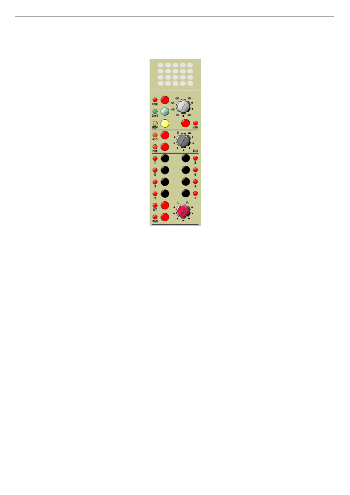
714 )URQW#SDQHO#0#PRQR#LQSXW#FKDQQHO#PRGXOH#;744
4.1.1. Oscillator
4.1.3 -20dBu PAD
4.1.4 Phase reverse
4,1.6 Direct output select
4.1.8 Sub-Group routing
4.1.9 Stereo
4.1.10 Pan
71414 2VFLOODWRU
4.1.2 Input gain
4.1.5 Phantom power 48V
4.1.7 Direct output level control
4.1.11 PAN-control
Press this button to apply a line-up tone to the input. The frequency and level of the
line up tone is set from the Stereo output, Comms, Osc & T a lkback module 8414.
71415 ,QSXW#JDLQ
This rotary control adjusts the MIC input gain between +10dBu and +60dBu.
71416 053G%#SDG
Pressing this button applies a -20dBu pad to the MIC input to accommodate for line
le vel sources @0dBu (0.775V) .
71417 3KDVH#UHYH UVH
Press this button to reverse the phase of the inc oming signal.
71418 7;9#3KDQWRP#SRZHU
Press this button to switch on 48V phantom power to any connected microphone,
Please note that the 48V phantom power is disabled on this channel if the OSC
switch is selected.
S-Type Revision S2005-6
Page 21

Mono input module 8411 4-3
71419 'LUHFW#RXWSXW#VHOHFW
Normally the dir ect output is fed post fader; pr essing PRE will source the signal prefader but post INS/EQ. Pressing MIC will override the PRE button (the PRE LED will
extinguish) and source the Direct Output post MIC amplifier. In this condition the HPfilter is still available.
7141: 'LUHFW#RXWSXW#OHYHO#FRQWURO
Use this rotary control to adjust the direct output level. Level control is from infinitity
to 0dB.
7141; 6XE0JURXS#URXWLQJ
The sub-group routing buttons allows a post fader signal to be routed to the SubGroups, with optional pan information, see 4.1.11. To route a signal f rom an input
channel to a Sub-Group, press the relevant numerical button in the Sub-Group section o f the input module.
5RXWLQJ#WR#PDWUL[#RXWSXW
Befo r e y ou can rou t e a si gnal t o t he ma tr ix out put s , t he si gn al ha s t o be r out ed t o on e
of the sub-groups (see 4.1.8). The signal can then be routed to the matrix output by
using the opposite controls on the 84 13 & 8415 module.
7141< 67#0#6WHUH R
Pressi ng th is but t on rout e s a po st pa n a nd f a de r s igna l t o t he st er eo ma st er. The pan
potentiometer will affect this signal regardless of whether the pan button is pressed,
see 4.1.1 1 .
714143 3DQ
Press this button to enable panning of the sub-groups via the pan potentiometer.
714144 3DQ#FRQWURO
Use this rotary control to pan the signal within the stereo field.
Revision S2005-6 S-Type
Page 22

4-4 Mono input module 8411
)URQW#SDQHO#0#PRQR#LQSXW#F KDQQHO#P R GXOH #;744
4.1.12 Pre/post f ader button w ith LED
4.1.13 SEN D O N -button with LED
4.1.14 SEND level contro l
714145 35(#0#SUH2SRVW#)DGHU
Press the PRE button to route the selected Auxiliary send pre-fader; the adjacent
LED indicates when pre fader mode is active.
714146 21#0#$X[LOLDU\#VHQG#2Q22II
Press the appropriate Auxiliary send ON-button to route the si gnal to one of the auxiliary busses; the adjacent LED will illuminate when the Auxiliary send is ON.
714147 $X[LOLDU\#VHQG#OHYH O#FRQWURO
Use this rotary control to adjust the level of the SEND signal.
4.1.15 St e reo S END 2 level & PAN control
4.1.16 St e reo S END 1 level & PAN control
714148 6WHUHR#$X[LOLDU\#VHQG#5#/(9(/#DQG#3$1#FRQWURO
Adjusts the Level (upper) and P an (lower) of the Stereo Auxiliary send 2.
714149 6WHUHR#$X[LOLDU\#VHQG#4#/(9(/#DQG#3$1#FRQWURO
Adjusts the Level (upper) and P an (lower) of the Stereo Auxiliary send 1.
S-Type Revision S2005-6
Page 23
Mono input module 8411 4-5
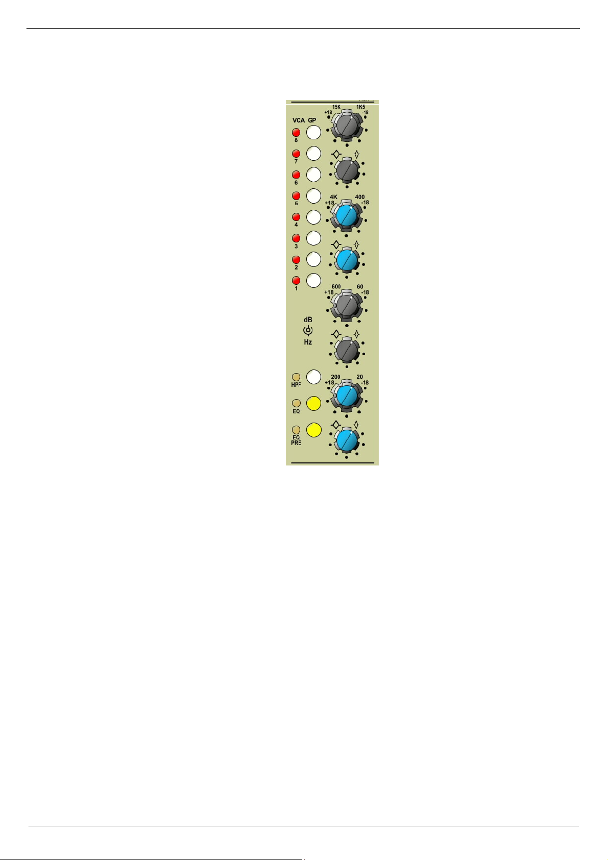
)URQW#SDQHO#0#PRQR#LQSXW#FKDQQHO#PRGXOH#;744
4.1.21 HF EQ Cut/Boost & Frequency
control 1k5Hz - 15kHz
4.1.22 HF Q-co ntrol
4.1.17 Assignment VCA Masters
4.1.23 H MF EQ C ut /B oost & F r eque nc y
control 400Hz - 4kHz
4.1.24 HMF Q-control
4.1.25 LMF EQ Cut/Boost & Frequency
control 600Hz - 60Hz
4.1.18 HP-filter button with LED
4.1.19 EQ-button with LED
4.1.20 EQ Pre button with LED
71414: 9&$#*3#0#$VVLJQPHQW#9&$#0DVWHUV
Using these buttons you can assign any of the eight VCA mast ers to any of the
inputs. This enables you to control the module’s output and mu te via the applicable
VCA Mas ter f ad er an d m ute con t rol s . N ormal ly, yo u w ou ld ass ig n a n i nput ch an nel to
one VCA Master, it is, however, possible to assign the input channel to two or more
VCA Masters, should this be required.
71414; +3)#0#+LJK#3DVV#)LOWHU#,Q22XW
Press ing the HPF button will insert the high pass filter in to the signal path. The HPF
has a cut-off frequency of 160Hz, with a slope of 12dB per octave. Note th at the HPF
is situated immediately after the microphone amplifier and is not switched with the
equalizer.
4.1.26 LMF Q-control
4.1.27 LF EQ Cut/Boost & Frequency
control 200Hz - 20Hz
4.1.28 LF Q-control
71414< (4#0#(4#,Q22XW
Press this button to switch the equalizer in circuit.
714153 (4#35(#0#(4#35(#EXWWRQ
Normally the equaliser is situated after the channel insert. Pressing the EQ PRE button will put the EQ before the channel insert.
Revision S2005-6 S-Type
Page 24

4-6 Mono input module 8411
714154 +)#(4#&XW2%RRVW#)#)UHTXHQF\#FRQWURO#4N8+]048N+]
This dual concentric potentiometer allows the centre frequency to be adjusted
between 1k5Hz and 15kHz (lower control) and the gain to be adjusted by ±18dB
(upper control). The gain control is centre detented.
714155 +)#40FRQWURO
The Q-co nt rol v a ries t he ba nd wid th of t he selec t ed f req ue nc y se lect ed as per 4 .1 . 21.
As ind icated on the fro nt panel when turned tow ards the low ‘Q’ symbol (Q approximately 1.0) will cause a wide bandwidth of frequencies to be affected around the
selected centre frequency. When set towards the high ‘Q’ symbol (‘Q’ approximately
3.0) a narrow band of frequencies will be affected around the centre frequency.
714156 +0)#(4#&XW2%RRVW#)#)UHTXHQF\#FRQWURO#733+]#0#7N+]
This dual concentric potentiometer allows the centre frequency to be adjusted
between 400Hz and 4kHz (lower control) and the gain to be adjusted by ±18dB
(upper control). The gain control is centre detented.
714157 +0)#40FRQWURO
The Q-co nt rol v a ries t he ba nd wid th of t he selec t ed f req ue nc y se lect ed as per 4 .1 . 23.
The function of the Q-contro l is described in 4.1.22.
714158 /0)#(4#&XW2%RRVW#)#)UHTXHQF\#FRQWURO#93+]#0#933+]
This dual concentric potentiometer allows the centre frequency to be adjusted
between 60Hz and 600Hz (lower control) and the gain to be adjusted by ±18dB
(upper control). The gain control is centre detented.
714159 /0)#40FRQWURO
The Q-control varies the bandw idth of the cut/boost frequency selected as per
4.1.25. The function of the Q-control is described in 4.1 22.
71415: /)#(4#&XW2%RRVW#)#)UHTXHQF\#FRQWURO#53+]#0#533+]
This dual concentric potentiometer allows the centre frequency to be adjusted
between 20Hz and 200Hz (lower control) and the gain to be adjusted by ±18dB
(upper control). The gain control is centre detented.
71415; /)#40FRQWURO
The Q-control varies the bandw idth of the cut/boost frequency selected as per
4.1.27. The function of the Q-control is described in 4.1.22.
S-Type Revision S2005-6
Page 25

Mono input module 8411 4-7
)URQW#SDQHO#0#PRQR#LQSXW#FKDQQHO#PRGXOH#;744
4.1.29 Insert + LED indicator
4.1.30 Mute
4.1.32 12-segment meter
4.1.34 Open fader LED
4.1.31 PFL
4.1.33 Fader
71415< ,16#0#,QVHUW#,Q22XW
Press this button to insert ex ternal equipment connected to the insert se nd and
return jack sockets on the rear panel of the module. Please note that the insert send
is permanently live and that the jack sockets are NOT norma lized. The insert point
can only be enabled by the front panel button. Note that selecting EQ PRE switches
the eq ualizer pre insert send.
714163 0#0#0XWH
Press this button to mute all POST FADER sign als from the input channel. When the
CHECK MUTE button is pressed on the Stereo master module (8414) this button will
act as a destructive solo, m uting all other channels in the desk while remaining unmuted itself.
Revision S2005-6 S-Type
Page 26

4-8 Mono input module 8411
714164 3)/
Press the PFL button to send th e pre-fader signal to the LISTEN module. Note that
selecting PFL will clear any previously selected PFL’s, unless HLD (Hold) is selected
on the Stereo master module 8414. If HLD is pressed, then the PFL will be added to
any previously selected signals on the Listen bus.
A temporary hold-function can be achieved by selecting and holding the desired
PFL. While holding down this switch you can add additional PFL channels as
required. Pressing any of the selected PFL switches a second time will clear the
selections a nd resume normal operation.
714165 0HWHU
This is a 12-segment level meter showing the signal level immediately pre-fader.
714166 )DGHU
This 100mm conductive plastic P&G fader is used to cont rol the signal level.
714167 23(1#0#2SHQ#IDGHU#/('
This LED illuminates when the fader is open and not muted locally or by a VCA master.
S-Type Revision S2005-6
Page 27

Mono input module 8411 4-9
715 5HDU#SDQHO#0#PRQR#LQSXW#FKDQQHO#PRGXOH#;744
MICROPHONE INPUT
INSERT SEND
INSERT RETURN
DIRECT OUTPUT
Inputs and outputs are electronically balanced and connected via 3-pin XLRs and follow the wiring convent ion:
PIN 1 = Screen
PIN 2 = In -phase signal (hot)
PIN 3 = Out -of-phase signal (cold)
The 0.25” TRS jack connectors use the wiring convention:
TIP = In-phase signal (hot)
RING = Out-of-phase signal (cold)
SLEEVE = Screen
IMPORTANT NOTE: Pin 1 on XLR connectors and the
‘sleeve’ connect ions on the jack sockets are connected
to the FRAME. This is to ensure that the console can
comply with the Electromagnetic Compatibility (EMC)
direc tive.
Revision S2005-6 S-Type
Page 28

4-10 Mono input module 8411
S-Type Revision S2005-6
Page 29

Stereo input module 8412 5-1
8 6WHUHR#LQSXW#PRGXOH#;745
The S-Type stereo input module has line level inputs for left and right channel
respectively. In addition, it features a full four-band para metric equaliser which c an
be switched to pre or post the insert point. An HP-filter with a cut-off frequency of
160Hz; slope 12 dB per octave is included.
The stereo input module incorporates a fully balanced direct output with level control;
normally post fader, but may be switched to pre fader, or even post input.
The module allows routing to eight sub-groups in true stereo with optional pan control. It can also route to a dedicated st ereo bus via the pan control. Additionally, it is
possible to route to eight Auxiliary busses; the first two of which are stereo on dual
concentric potenti ometers - level on t he upper control and pan on the lower control.
The remaining six are mono sends with level control. All eight sends can be enabled
and sel ected to be sourced pre or post fader on an individual basis.
Each stereo input channel can be assigned to up to eight VCA masters.
The 84 12 stereo input module is equipped with a fully b alanced insert send and
return - the send stays live irrespective of whether the insert button is pressed. Also,
included on the module are PFL and Mute buttons - inclusive of a destructive solo
function.
The module is fitted with a 100mm P&G fader, and located next to it, a 12-segment
meter with a range of +18dB to -36dB (meter source is pre fader). There is also a
fader-open LED, which, when extinguished, indicates that either the channel fader is
closed or muted, or an assigned VCA Master is muted or pulled down to infinity.
Following pages describes the 8412 module in detail.
Revision S2005-6 S-Type
Page 30

5-2 Stereo input module 8412
814 )URQW#SDQHO#VWHUHR#LQSX W#PRGXOH#;745
5.1.2 Oscillator
5.1.3 Mono
5.1.4 Phase reverse
5.1.5 Input
5.1.6 Pre fader
5.1.1 Input gain
5.1.7 Direct output level
5.1.8 Sub-group routing
5.1.9 Stereo
5.1.10 Pan
81414 ,QSXW#JDLQ#/HIW25LJKW
This dual concentric rotary control (Left - upper control, Right - lower control) is used
to adjust the input gain be tween infinity and +10dB.
81415 26�#2VFLOODWRU
Press this button to apply a line up tone to the input. The frequency and level of the
line up tone is controlled from the 8414 module.
81416 0RQR
Press this button to sum left and right channel to mono.
5.1.11 PA N contro l
81417 5(9#/#0#3KDVH#UHYHUVH#OHIW#F KDQQHO
Pressing this button reverses the phase of the incoming left signal.
81418 ,QSXW
Press this button to route the line input - post input amplifier - to the Direct output.
S-Type Revision S2005-6
Page 31

Stereo input module 8412 5-3
81419 35(#0#3UH#IDGHU
Press this button to route the pre-fader signal to Direct Output. If INPUT or PRE are
not selected the Direct Output is sourced post fader.
8141: 'LUHFW#RXWSXW#OHYHO#FRQWURO
Use this rotary control to adjust the direct output level. Level control is from infinity to
0dB.
8141; 6XE0JURXS#URXWLQJ
The su b-g r oup r ou t ing b u tt o ns all o w po st fader signal to be r out ed to th e s ub -gr oup s ,
with optional pan information, see 5.1.11. To route a signal fr om an input channel to
a sub-group, press the relevant numerical button on the sub-group.
5RXWLQJ#WR#PDWUL[#RXWSXW
Befo r e y ou can rou t e a si gnal t o t he ma tr ix out put s , t he si gn al ha s t o be r out ed t o on e
of the sub-groups (see 5.1.8). The signal can then be routed to the matrix sends b y
using the appr opriate contro ls on the 8413 & 8415 modules.
8141< 67#0#6WHUH R
Pressing this button routes a post pan and fader signal to the Stereo master. The
PAN potentiomete r will affect this signal regardless of w hether the pan button is
presse d, see 5.1.1 1.
814143 3$1
Press this button to enable panning of the sub-groups via the PAN potentiometer.
814144 3$1#FRQWURO
Use this rotary control to pan the signal within the stereo field.
Revision S2005-6 S-Type
Page 32

5-4 Stereo input module 8412
)URQW#SDQHO#VWHUHR#LQSXW#FKDQQHO#PRGXOH#;745
5.1.12 Pre fader button with LED
5.1.13 Aux send ON-button with LED
5.1.14 Aux send level control
814145 35(#0#3UH2SRVW#IDGHU
Press the PRE button to route the selected Auxiliary send pre-fader; the adjacent
LED indicates when pre-fader mode is active.
814146 21#0#$X[LOLDU\#VHQG#2Q22II
Press the appropriate Auxi liary send ON button to route the si gnal to one of the Auxiliary busses; the LED will illuminate when the Auxiliary send is ON.
814147 $X[LOLDU\#VHQG#OHYH O#FRQWURO
Use this rotary concentric control to adjust the level of the Auxiliary send.
5.1.15 Send level/pan control Aux 2
5.1.16 Send level/pan control Aux 1
814148 6WHUHR#$X[LOLDU\#VHQG#5#/(9(/#DQG#3$1#FRQWURO
Adjusts the level (upper control) and PAN (lower control) of stereo auxi liary send 2.
814149 6WHUHR#$X[LOLDU\#VHQG#4#/(9(/#DQG#3$1#FRQWURO
Adjusts the level (upper control) and PAN (lower control) of Stereo Auxiliary send 1.
S-Type Revision S2005-6
Page 33

Stereo input module 8412 5-5
)URQW#SDQHO#VWHUHR#LQSXW#FKDQQHO#PRGXOH#;745
5.1.21 HF EQ Cut/ Boost & Frequency
control 1k5Hz - 15 kH z
5.1.22 HF Q-control
5.1.17 Assignment VCA Masters
5.1.18 HP filter IN/OUT
5.1.19 Equaliser IN/O UT
5.1.20 Equaliser Pre insert
81414: 9&$#*3#0#$VVLJQPHQW#9&$#0DVWHUV
5.1.23 HMF EQ Cut/Boost & Frequency
control 400Hz - 4kHz
5.1.24 HMF Q-control
5.1.25 LMF EQ Cut/Boos t & Frequency
contro l 60Hz - 600Hz
5.1.26 LMF Q-control
5.1.27 LF EQ Cut/Boost & Fr equency
contro l 20Hz - 200Hz
5.1.28 LF Q-control
Using these buttons you can assign any of the eight VCA Mast ers to any of the
input s. This enables you to control the module’s output level and mute via the applicable VCA Master fader and mute control s. Normally, you would assign an input
channel to one VCA Master. It is, however, possible to assign the input channel to
two or more VCA Masters, should this be required.
81414; +3)#0#+LJK#3DVV#)LOWHU#,Q22XW
Pressing this button will insert the highpass filter into the signal path. The HP-filter
has a cut-off frequency of 160Hz; slope is 12 dB per octave. Note tha t the HPF is situated immediately aft er the MIC amplifier and is not switched with the equalizer.
81414< (4#0#(4#,Q22XW
Press this button to insert the equaliser into the signal path.
814153 (4#0#(4#35(#EXWWRQ
Normally the equalizer is situated after the channel insert. Pressing the EQ PRE button will switch the EQ pre the channel insert.
Revision S2005-6 S-Type
Page 34

5-6 Stereo input module 8412
814154 +)#(4#&XW2%RRVW#)#)UHTXHQF\#FRQWURO#4N8+]#0#48N+]
This dual concentric control allows the centre frequency to be adjusted between
1k5Hz to 15kHz (lower control) and the gain to be adjusted by ±18dB (upper control).
The gain control is centre detented.
814155 +)#40FRQWURO
The Q-control varies the bandw idth of the selec ted frequency when gain is applied
as per 5.1.21. As indicated on the front panel when turned towards the low ‘Q’ symbol (Q approximately 1.0) wi ll cause a wide bandwidth of frequencies to be affected
around the selected centre frequency. When set toward the high ‘Q’ symbol (‘Q’
approximately 3.0) a narrow band of frequencies will be a ffected aro und the centre
frequency .
814156 +0)#(4#&XW2%RRVW#)#)UHTXHQF\#FRQWURO##733+]#0#7N+]
This dual concentric control allows the centre frequency to be adjusted between
400Hz to 4kHz ( lower control) and th e gain to be adjusted by±18dB (upper control).
The gain control is centre detented.
814157 +0)#40FRQWURO
The Q-control varies the bandw idth of the cut/boost frequency selected as per
5.1.23. The function of the Q-control is described in 5.1.22.
814158 /0)#(4#&XW2%RRVW#)#)UHTXHQF\#FRQWURO#93+]#0#933+]
This dual concentric control allows the centre frequency to be adjusted between
60Hz to 600Hz (lower control) and the gain to be adjusted by ±18dB (upper control).
The gain control is centre detented.
814159 /0)#40FRQWURO
The Q-control varies the bandw idth of the selec ted frequency when gain is applied
as per 5.1.25. The func tion of the Q-control is described in 5.1. 22.
81415: /)#(4#&XW2%RRVW#)#)UHTXHQF\#FRQWURO#53+]#0#533+]
This dual concentric control allows the centre frequency to be adjusted between
20Hz to 200Hz ( lower control) and th e gain to be adjusted by±18dB (upper control).
The gain control is centre detented.
81415; /)#40FRQWURO
The Q-control varies the bandw idth of the selec ted frequency when gain is applied
as per 5.1.27. The func tion of the Q-control is described in 5.1. 22.
S-Type Revision S2005-6
Page 35

Stereo input module 8412 5-7
)URQW#SDQHO#VWHUHR#LQSXW#FKDQQHO#PRGXOH#;745
5.1.29 Insert
5.1.30 Mute
5.1.32 Dual 12-segment level meter
5.1.34 Open fader LED
5.1.31 PFL
5.1.33 Fader
81415< ,QVHUW#,Q22XW
Press this switch to insert external equipment connected to the insert send and
return jack sockets on the rear panel of the module. Please note that the insert send
is permanently live and that the jack sockets are NOT norma lized. The insert point
can only be enabled by the front panel button. Note that selecting EQ PRE switches
the eq ualizer pre insert send.
814163 0XWH
Press this button to mute all post-fader signals f rom the input channel. When the
CHECK M UTE bu tton is pressed on the stereo mast er module (8414) the channel’s
Mute will act as a destructive solo, muting all oth er channels in the desk while
remaining un-muted i tself.
Revision S2005-6 S-Type
Page 36

5-8 Stereo input module 8412
814164 3)/
Press this button to send the pre-fader signal to the LISTEN module. Note that
selecting PFL will clear any previously selected PFL’s, unless HLD (Hold) is selected
on the stereo master module 8414. If HLD is pressed, then the PFL will be added to
any of the previously selected signals on the Listen bus.
A tempo r ary ho ld func t io n c an be ach ieved by se l ect ing an d h ol ding t he desi re d PFL.
Whil e holding down t his switch you can add additional PFL channels as required.
Pressing any of the selected PFL switches a second time will clear the selections
and resume normal operation.
814165 'XDO#450VHJPHQW#OHYHO#PHWHU
12-segment level meters showing the channel signal level immediately pre-fader.
814166 )DGHU
100mm plastic conductive P & G fader used to control the signal level.
814167 2SHQ#IDGHU#/('
This LED illuminates when the fader is open and not muted locally or by a VCA Master.
S-Type Revision S2005-6
Page 37

Stereo input module 8412 5-9
815 5HDU#SDQHO#VWHUHR#LQSXW#FKDQQHO#PRGXOH#;745
LINE INPUT LEFT
INSERT SEND LEFT
INSERT RETURN LEFT
LINE INPUT RIGHT
INSERT SEND RIGHT
INSERT RETURN RIGHT
OUTPUT LEFT
OUTPUT RIGHT
Inputs and outputs are electronically balanced and connected via 3-pin XLRs and follow the wiring convention:
PIN 1 = Screen
PIN 2 = I n-phase signal (hot)
PIN 3 = Out-of-phase signal (cold)
The 0.25” TRS jack connectors use the wiring convention:
TIP = In-phase signal (hot)
RING = Out-of-phase signal (cold)
SLEEVE = Screen
IMPORTANT NOTE: Pin 1 on XLR connectors and the
‘sleeve’ connections on the jack socket s are connected
to the FRAME. This is to ensure that the console can
comply with the Electromagnetic Compatib ility (EMC)
directive.
Revision S2005-6 S-Type
Page 38

5-10 Stereo input module 8412
S-Type Revision S2005-6
Page 39

Group, matrix and aux output - stereo 8413, mono 8415 6-1
9 *URXS/#PDWUL[#DQG#DX[#RXWSXW#0#
VWHUHR#;746/#PRQR#;748
Each console can have up to 6 x 8415 and 2 x 8413 (note that the illustration depicts
the stereo version) which will give you access to all the available Group, Matrix and
Auxiliary outputs of the desk.
Each group module comprises of a sub-group output with a full size P&G f ader, 12segment meter, PFL, Mute and Insert. It is possible to send the sub-group signal to
the stereo bus with panning. In addition, there is a switch to change the send to
matrix to be pre rather than post sub-group fader.
The matr ix se nd s on t he mod ul e con si st s o f 8 indi vi du al rou t ing b u t to ns and four dual
concentric potenti ometers for the send level - odd send (upper control), e ven send
(lower control). This leads to the Matrix master output, which has a potentiometer for
output level con tr o l, 12-segme nt meter, PFL, Mu te an d Ins ert.
The final output on the module is the Auxiliary Master output, which comprises of a
potentiometer for level control, 12-segment meter (2 in the case of t he stereo 8413),
PFL and Mute.
Inputs and out puts are electronically balanced on 6.3mm jack sockets, except the
sub-group and Matrix master outputs that are available on XLR connectors.
The module mix bus coding for the Sub-group, Matrix and Auxiliaries is manually
selectabl e using 4-way jumpers (8-way for the two stereo auxiliary masters). For
details on this, see B. Mix bus coding
The VCA Master is located at the bot tom of the module an d consists of a 100mm
P&G fader and mute control.
Revision S2005-6 S-Type
Page 40

6-2 G roup, matrix an d aux output - stere o 8413, mono 8415
914 )URQW#SDQHO#JURXS/#PD WUL[#DQG#DX[#RXWSXW=##########
6WHUHR#;746#0#0RQR#;748
6.1.2. Auxiliary output level
6,1,1 Signal level meters
6.1.3 PFL
6.1.4 Mute
91414 6LJQDO#OHYHO#PHWHUV
12-seg men t le v el me ter s di splaying the Au xi li ary mast e r out put level. Meter sour ce is
post Auxiliary Master level control.
91415 $ X[LOLDU\#0DVWHU#RXWSXW#OHYHO
This rotary controls adjusts the signal level of the auxiliary master output. Level control gain range from infinity to 0dB.
91416 3)/
Press this button to listen to the auxiliary master output signal pre fader.
91417 0XWH
Press this button to mute the auxiliary master output signal.
S-Type Revision S2005-6
Page 41

Group, matrix and aux output - stereo 8413, mono 8415 6-3
)URQW#SDQHO#JURXS/#P D WUL[#DQG#DX[ #RXWSXW=####################
6WHUHR#;746#0#0RQR#;748
6.1.5 Matrix master output sign al level meter
6.1.10 Matrix sends IN/OUT
6.1.6 M atrix output signal level control
6.1.7 PFL
6,1,8 Insert with LED
6.1.9 Mute
6.1.11 Matrix 7 & 8 send level
6.1.12 Matrix 5 & 6 send level
6.1.13 Matrix 3 & 4 send level
91418 0DWUL[#0DVWHU#OHYHO#PHWHU
12-s egment level meter showing the signal level of the matrix maste r output.
91419 0DWUL[#0DVWHU#OHYHO#FRQWURO
This rotary control is used to adjust the signal level of the matrix master output.
9141: 3)/
Press this button to listen to the matrix master pre-fader.
9141; ,QVHUW
Press this button to connect the pre-f ader send/return insert jacks into the signal
path. Please note that the insert send is permanently live and that the jack sockets
are NOT normalized.
6.1.14 Matrix 1 & 2 send level
Revision S2005-6 S-Type
Page 42

6-4 G roup, matrix an d aux output - stere o 8413, mono 8415
9141< 0XWH
Press this button to mute the matrix master.
914143 0DWUL[#VHQGV#,12287
Press any of these buttons to turn the appropriate matrix sends ON or OFF.
914144 0DWUL[#:#)#;#VHQG#OHYHO
These r ot ary co nt rol s a r e use d t o adj us t t he ou tput si g nal l e vels of the matri x s en ds 7
and 8. Upper con trol for Matrix send 7 and lower control for Matrix send 8.
914145 0DWUL[#8#)#9#VHQG#OHYHO
These r ot ary co nt rol s a r e use d t o adj us t t he ou tput si g nal l e vels of the matri x s en ds 5
and 6. Upper con trol for Matrix send 5 and lower control for Matrix send 6.
914146 0DWUL[#6#)#7#VHQG#OHYHO
These r ot ary co nt rol s a r e use d t o adj us t t he ou tput si g nal l e vels of the matri x s en ds 3
and 4. Upper con trol for Matrix send 3 and lower control for Matrix send 4.
914147 0DWUL[#4#)#5#VHQG#OHYHO
These r ot ary co nt rol s a r e use d t o adj us t t he ou tput si g nal l e vels of the matri x s en ds 1
and 2. Upper con trol for Matrix send 1 and lower control for Matrix send 2.
S-Type Revision S2005-6
Page 43

Group, matrix and aux output - stereo 8413, mono 8415 6-5
)URQW#SDQHO#JURXS/#P D WUL[#DQG#DX[ #RXWSXW=####################
6WHUHR#;746#0#0RQR#;748
6.1.15 Sub-group to stereo routing
6.1.17 Sub-group level meter
6.1.19 PFL
6.1.20 Matrix Pre
6.1.16 PAN control
6.1.18 Fader
6.1.21 Insert
6.1.22 Mute
914148 67#0#6XE#JURXS#VWHUHR
Press this button to send the sub-group post fader signal to the stereo master with
optiona l pa nning.
914149 3$1#FRQWURO
This rotary control is used to place the sub-group signal at the desired point in the
stereo field w hen routing to the Stereo master.
91414: 6XE#JURXS#OHY HO#PHWHU
12-segment level meter displaying the signal level of the sub-group. Meter source is
post sub-group fader.
91414; )DGHU
100mm plastic conductive P & G fader used to adjust the sub-group output level.
Revision S2005-6 S-Type
Page 44

6-6 G roup, matrix an d aux output - stere o 8413, mono 8415
91414< 3)/
Press the but ton to listen to the sub-group signal pre-fader.
914153 0DWUL[#3UH
Press this button (MAT PRE) to source the matrix sends pre sub-group fader. This
allows the sub-group to be used as an additional send without altering matrix send
levels.
914154 ,QVHUW
Press this button to connect the pre-fader send/return insert jacks into the signal
path. Please note that the insert send is permanently live and that the jack sockets
are not normalized.
914155 0XWH
Press this button to mute the sub-group output.
S-Type Revision S2005-6
Page 45

Group, matrix and aux output - stereo 8413, mono 8415 6-7
)URQW#SDQHO#JURXS/#PDWUL[#DQG#DX[#RXWSXW=########################
6WHUHR#;746#0#0RQR#;748
6.1.23 VCA Master - Mute
6.1.24 VCA Master - Fader
914156 0#0#9&$#0DVWHU#0#0XWH
Press this button to mute the VCA Master and associated input channels.
914157 9&$#0DVWHU#0#)DGHU
100mm plastic conductive P & G fader used to control the VCA Master level.
Revision S2005-6 S-Type
Page 46

6-8 G roup, matrix an d aux output - stere o 8413, mono 8415
915 5HDU#SDQHO#JURXS/#PDWUL[#DQG#DX[ #RXWSXW= ####################
6WHUHR#;746#0#0RQR#;748
8413 stereo 8415 mono
Input s and outputs are electronically balan c ed and connected v ia 3-pin XLRs and follow the wiring convention:
PIN 1 = Screen
PIN 2 = In-phase signal (h ot)
PIN 3 = Out -of-phase signal (cold)
The 0.25” TRS jack connectors use the wiring convention:
TIP = In-phase signal (hot)
RING = Out-of-phase signal (cold)
SLEEVE = Screen
IMPORTANT NOTE: Pin 1 on XLR connectors and t he
‘sleeve’ connections on the jack sockets are connected
to the FRAME. This is to ensure that the console can
comply with the Electromagnetic Compatibility (EMC)
directive.
S-Type Revision S2005-6
Page 47

Stereo output, Co mms, Osc and Talkback module 8414 7-1
: 6WHUHR#RXWSXW/#&RPPV/#2VF#DQG#
7DONEDFN#PRGXOH#;747
The 84 14 module contai ns the main stereo output with a full size 100mm fader, 12segment meters for left and right channels in addition to PFL, Mute and Insert.
The module enables you to send the stereo mix to the matrix outputs via individual
routi ng b utt on s a nd du al conc en tr ic po tent i om et ers - od d nu mbe r s g oe s to le ft (u pp er
control), even number goes to right (lower control). In addition, each pair of sends
has a sum-to-mono feature.
The oscillat or can be switched to 100Hz, 1kH z and 10kHz and can be routed to the
channels and/or the sub-groups.
The talkback section contains the same mic amplifier as found on the mono input
channels with optional 48V and HPF. The talkback signal can then be routed to the
auxil iary sends and sub-groups.
The listen output level is controlled via a dedicated level control. Two dedicated 12segment level met ers provide vi sual feedback. Mute, Hold and Clear butto ns are
included.
In normal mode, the PFLs are self cancelling, i.e. pressing any PFL buttons on the
console will clear any previous selection. By selecting the PFL Hold switch it is possible to enable multiple PFL switches simulataneously .
A temporary hold function can be achieved by selecting and holding the desired PFL
switch, while adding additional PFLs as required. Pressing the PFL switch a second
time will clear the selected channels and resume normal operation.
Revision S2005-6 S-Type
Page 48

7-2 Stereo output, Comms, Osc and Talkback module 8414
:14 )URQW#SDQHO#6WHUHR#RXWSXW /#&R PPV/#2VF#DQG#
7DONEDFN#PRGXOH#;747
7.1.1 Talkback MIC input
7.1.2 Check mute
7.1.4 48V IN/OUT
7.1.6 HP filter
7.1.7 Talkback AUX select
7.1.8 Talkback group select
7.1.9 Mute
:1414 7DONEDFN#PLFURSKRQH#LQSXW
7.1.3 Mute All
7.1.5 Talkback signal level
7.1.10 Talkback activate
A 3-pin female XLR is pro v ided at th e top of th e 81 41 m odul e t o al l ow t he conne ct i on
of a talkback microphone. The microphone amplifier gain control is l ocated in the
lower section of this module.
Note: Talkback microphone is NOT included with the S-Type.
:1415 &KHFN#PXWH
Enab ling CHECK MUTE allows an operator to use the input channel MUTE button s
in a Destructive Solo mode.
:1416 0XWH#$OO
The MUTE ALL feature mutes all channels, master outputs, (including sub-group,
matrix and auxiliary master) and Stereo master.
S-Type Revision S2005-6
Page 49

Stereo output, Co mms, Osc and Talkback module 8414 7-3
:1417 7;9#,12287
Press this button to provide +48V phantom power to the Talkback microphone XLR.
:1418 7DONEDFN#VLJQDO#OHYHO
This rotary control adjusts the Talkback MIC in put gain betwee n 10dBu and 60dBu.
:1419 +3#ILOWHU#,12287
Press this button to activate the highpass filter post Talkback microphone amplifier.
:141: 7 DONEDFN#$8;#VHOHFW
These assignment switches allow talkback to be routed to any of the auxiliary busses
on an in dividual basis.
:141; 7 DONEDFN#JURXS#VHOHFW
These assignment switches allow talkback to be routed to any of the sub-group busses on an individual basis.
:141< 0XWH
Pressing this button will mute the Talkback feature. Pressing the TB button (7.1.10)
will over-ride the MUTE.
:14143 7DONEDFN#DFWLYDWH
Pressing the TB button will activate th e talk-back featur e across the selected auxiliary and sub-group busses..
Revision S2005-6 S-Type
Page 50

7-4 Stereo output, Comms, Osc and Talkback module 8414
)URQW# SDQHO#6WHUHR#RXWSXW/# &RPP V/#2VF# DQG#7DONEDFN
PRGXOH#;747
7.1.11 Littlites ON/OFF
7.1.13 Oscillator line up tone 10kHz
7.1.14 O scillator line up tone 1kHz
7.1.15 Oscillator line up tone 100Hz
7.1.17 Channels
7.1.19 Listen output level meter
7.1.23 Mu t e
7.1.24 Headphones Mute
7.1.12 Littlite brightness
7.1.16 Oscillator line up signal level
7.1.18 G roups
7.1.20 Listen output signal level
7.1.21 H ol d
7.1.22 C le ar
7.1.25 Headphones signal output level
:14144 /LWWOLWHV#2122))
Press this button to switch the littlites ON/OFF. ON is indicated by the adjacent LED
illuminating.
:14145 /LWWOLWH#EULJKWQHVV
This rotary control enables you to adjust the brightness of the littlites.
:14146 2VFLOODWRU#OLQH0XS#WRQH#43N+]
Enabling this switch activates a 10kHz line up tone, which is available for selected
input channels and/or all sub- groups (see 7.1.17 and 7.1.18).
:14147 2 VFLOODWRU#OLQH0XS#WRQH#4N+]
When both 10kHz and 100Hz oscillator switches are in the OFF posit ion, a 1kHz line
up tone is available for selected input channels and/or all sub-groups (see 7.1.17 and
7.1.18).
S-Type Revision S2005-6
Page 51

Stereo output, Co mms, Osc and Talkback module 8414 7-5
Note: When both 10kHz
and 100Hz oscilla tor
switches are in the ON position, the oscillator will
default to 10kHz. Only the
10kHz LED will be
illumin ate d.
Note: The OSC button will
need to be enabled on the
desired input modules.
Level control gain range
from infinity to 0dB.
:14148 2VFLOODWRU#OLQH0XS#WRQH#433+]
Enabling this switch activates a 100Hz line up tone, which is available for selected
input channels and/or all sub-groups .
:14149 2VFLOODWRU#OLQH0XS#VLJQDO#OHYHO
Use this rotary control t o set the level of the line up tone select ed.
:1414: &KDQQHOV
Press this button to apply a line up tone to the channel(s) selected. Note: The OSC
but ton will need to be enabled on the desired input modules.
:1414; *URXSV
Press this button to assign line-up tone to all sub-group busses.
:1414< /LVWHQ#RXWSXW#OHYHO#PHWHU
Dual 12-segment LED m eter indicatin g the signal level of the Listen output.
:14153 /LVWHQ#RXWSXW#VLJQDO#OHYHO
Use this rotary control t o adjust the signal level of the Listen output. Level control
gain r ange from infinity to +10dBu.
:14154 +ROG
When activated, the HLD switch provides a PFL latching function, whereby multiple
PFL switch es can be enabled simultaneously. All can be cleared by pressi ng the
CLR button (7.1.22).
:14155 &OHDU
Pressing this butt on will clear all enabled PFL s witches.
:14156 0XWH
Press this button to mute the listen output.
:14157 +HDGSKRQHV#0XWH
Press this button to mute the signal sent to the headphones.
:14158 +HDGSKRQHV#RXWSXW#VLJQDO#OHYHO
Use this rot ary contr ol to adjust the signal level to the headphones. Headphone level
contr ol range from i nfinity to 0dB.
Revision S2005-6 S-Type
Page 52

7-6 Stereo output, Comms, Osc and Talkback module 8414
)URQW# SDQHO#6WHUHR#RXWSXW/# &RPP V/#2VF# DQG#7DONEDFN
PRGXOH#;747
7.1.26 Right channel to matrix output 8
7.1.27 Sum L+R to matrix output 7+8
7.1.28 Left channel to matrix output 7
7.1.29 Right channel to matrix 6
7.1.30 Sum L+R to matrix output 5+6
7.1.31 Left channel to matrix output 5
7.1.32 Right channel to matrix output 4
7.1.33 Sum L+R to matrix output 3+4
7.1.34 Left channel to matrix output 3
7.1.35 Right channel to matrix output 2
7.1.36 Sum L+R to matrix output 1+2
7.1.37 Left channel to matrix output 1
:14159 5LJKW#FKDQQHO#WR#PDWUL[#RXWSXW#;
Press this button to route the stereo master right channel signal to matrix send 8.
7.1.38 Output level to matrix 7+8
7.1.39 Output level to matrix 5+6
7.1.40 Output level to matrix 3+4
7.1.41 Output level to matrix 1+2
:1415: 6XP#/.5#WR#PDWUL[#RXWSXW#:.;
Press this button to mono sum the stereo master. The mono sum is then available to
be routed to matrix send s 7 and/or 8.
:1415; /HIW#FKDQQHO#WR#PDWUL[#RXWSXW#:
Press this button to route the stereo master left channel signal to matrix send 7.
:1415< 5LJKW#FKDQQHO#WR#PDWUL[#RXWSXW#9
Press this button to route the stereo master right channel signal to matrix send 6.
:14163 6XP#/.5#WR#PDWUL[#RXWSXW#8.9
Press this button to mono sum the stereo master. The mono sum is then available to
be routed to matrix send s 5 and/or 6.
:14164 /HIW#FKDQQHO#WR#PDWUL[#RXWSXW#8
Press this button to route the stereo master left channel signal to matrix send 5.
S-Type Revision S2005-6
Page 53

Stereo output, Co mms, Osc and Talkback module 8414 7-7
:14165 5LJKW#FKDQQHO#WR#PDWUL[#RXWSXW#7
Press this button to route the stereo master right channel signal to matrix send 4.
:14166 6XP#/.5#WR#PDWUL[#RXWSXW#6.7
Press this button to mono sum the stereo master. The mono sum is then available to
be routed to matrix sends 3 and/or 4.
:14167 /HIW#FKDQQHO#WR#PDWUL[#RXWSXW#6
Press this button to route the stereo master left channel signal to matrix send 3.
:14168 5LJKW#FKDQQHO#WR#PDWUL[#RXWSXW#5
Press this button to route the stereo master right channel signal to matrix send 2.
:14169 6XP#/.5#WR#PDWUL[#RXWSXW#4.5
Press this button to mono sum the stereo master. The mono sum is then available to
be routed to matrix sends 1 and/or 2.
:1416: /HIW#FKDQQHO#WR#PDWUL[#RXWSXW#4
Press this button to route the stereo master left channel signal to matrix send 1.
:1416; 2XWSXW#OHYHO#WR#PDWUL[#:.;
These rotary controls are used to adjust the output signal levels of matrix sends 7
and 8. Upper control for matrix send 7 and lower control for matrix send 8.
:1416< 2XWSXW#OHYHO#WR#PDWUL[#8.9
These rotary controls are used to adjust the output signal levels of matrix sends 5
and 6. Upper control for matrix send 5 and lower control for matrix send 6.
:14173 2XWSXW#OHYHO#WR#PDWUL[#6.7
These rotary controls are used to adjust the output signal levels of matrix sends 3
and 4. Upper control for matrix send 3 and lower control for matrix send 4.
:14174 2XWSXW#OHYHO#WR#PDWUL[#4.5
These rotary controls are used to adjust the output signal levels of matrix sends 1
and 2. Upper control for matrix send 1 and lower control for matrix send 2.
Revision S2005-6 S-Type
Page 54

7-8 Stereo output, Comms, Osc and Talkback module 8414
)URQW# SDQHO#6WHUHR#RXWSXW/# &RPP V/#2VF# DQG#7DONEDFN
PRGXOH#;747
7.1.38 External input
7.1.40 12-segment output level meter
7.1.42 PFL
7.1.43 Matrix Pre
7.1.44 Insert
7.1.45 Mute
7.1.39 External input level control
7.1.41 Fader
:14175 ([WHUQDO#LQSXW
Press this button to route th e external input source to the main stereo bus.
:14176 ([WHUQDO#LQSXW#OHYHO#FRQWURO
Use this rotary control to adjust the input level of the external input signal. Level control gain range from infinity to +10dB.
:14177 450VHJPHQW#RXWSXW#OHYHO#PHWHU
This dual 12 segment LED meter indicates the signal level of the stereo master.
Meter source is post Stereo master fader.
S-Type Revision S2005-6
Page 55

Stereo output, Co mms, Osc and Talkback module 8414 7-9
:14178 )DGHU
Full s ize 100mm P & G conductive plastic fad er adjusting the main Stereo master
output signal.
:14179 3)/
Press this button to listen to the stereo master pre-fader.
:1417: 0DWUL[#3UH
Press this button (MAT PRE) to source the matrix sends pre stereo master fader.
This allows the st ereo master le vel to be alt ered without changing matrix send levels.
:1417; ,QVHUW
Press this button to connect the pre-fader send/return jacks into the signal path.
:1417< 0XWH
Press this button to mute the stereo master output.
Revision S2005-6 S-Type
Page 56

7-10 Stereo output, Comms, Osc and Talkback module 8414
:15 5HDU#SDQHO#6WHUHR#RXWSXW/#&RPPV/#2VF#DQG#
7DONEDFN#PRGXOH#;747
Inputs and outputs are electronically balan c ed and connected via 3-pin XLRs and follow the wiring convent ion:
PIN 1 = Screen
PIN 2 = In-phase signal (hot)
PIN 3 = Out -of-phase signal (cold)
The 0.25” TRS jack connector for the external input is
unbalanced:
TIP = LEFT
RING = RIGHT
SLEEVE = Screen
IMPORTANT NOTE: Pin 1 on XLR connectors and the
‘sleeve’ connect ions on the jack sockets are connected
to the FRAME. This is to ensure that the console can
comply with the Electromagnetic Compatibility (EMC)
direc tive.
S-Type Revision S2005-6
Page 57

$SSHQGLFHV
$1##,PSRUWDQW#LQIRUPDWLRQ#UHJDUGLQJ#(0&#
In live sound applications, it is normal f or the console to be situa ted a long way from
its sound sources and ampl ifier/loudspeaker sy stem. This inevitably means cable
runs of m an y h un dre ds of me tre s . I n or de r t o mi nimi z e n oi se an d int e rf e ren ce pi c k u p
on the c ables, it is generally agreed that the “balanced lin e” connection system is
essent ial. On the S-Type console, all inputs and outputs (including insert points ) are
full y balanced. The only exception to this is the external input on the ste reo master,
which is unbalanced.
Great att en tio n i s pa i d t o the co nst ruct i on an d la y o ut of all pr in te d cir c ui t b oa rds u se d
in the console. It is relatively simple to design high performance circuits that work
perfectly on the bench, but it is somewhat more difficult (and costly) to engineer the
printed circuit boards in a way t hat allows this performance to be re peated in produc tion . CADAC use layout techniques that have been developed ove r the years to minimize variations in production quality and in the case of logic circuits, to absorb any
interference that may be generated inside the console.
APP-I
The part of a console that is mo s t pr on e to interferenc e pick u p is the mi xi ng bus.
Mixing bus wires have dimension s large enough to allow them to be one quarter of a
wav e - leng t h of ma n y me di um w a v e rad io t ran smi ss ions . In ot her wor d s , a mix in g b u s
can be an antenna for radio reception. Since the airwaves are becoming ever more
pollu ted with radio t ransmissions, CADAC use a balanced bus s ystem for all mixing
requirements.
In gen eral, analog audio circuits do not tr ansmit unwanted signals into the surrounding air space (unless a poor design or component fault causes a circuit to pr oduce
oscil la tio n) . O n th e o t he r ha nd , u si ng a com pute r (em be dde d proc es sor or co nt rol l er )
to handle any form of automation always produces a wide range of unwanted high
frequency radiation. Some artifacts from this
system
neered to min imize any pote ntial interference generated inside th e system and to
pre vent radiation into the environment. The techniques used also have the adva ntage of making the system immune to external interference.
On the 1st January 1996, new European legislation known as the EMC Directive
came into force. The EMC Directive requires that all el ectronic equipment manufactured or i mpo rted f o r sal e in th e EEC m ust no t e mit el ec tro ma gne t ic inte rf e r en ce tha t
can impair the performance of other sys tems or sub-systems. Similarly, the product
must also be immune to a wide range of natural and man- made electromagnetic
inte rfer ence in its operating environment. Many countries outside the EEC are also
developing or have already put into place similar legislation. In order to conform to
these rules, a number of changes were required to the basic design of our consoles
and modules. One of the main changes is:
All cable ‘screen’ connections are bonded to the frame.
radiate interference to external equipment. CADAC designs are engi-
and
cause interference to the audio
can
The figure overleaf shows the required connection scheme for XLR connectors.
Please note that in the case of ‘line’ or ‘free’ connectors (XLRs on cables), the 'pigtail ' formed from the cable screening brai d should be as short as practical and soldered to the
halfway between the
The twisted pair should be left 'twisted' ri ght up to the signal solder tags.
Revision S2005-6 S-Type
shell ground tag
. Pin 1 is then connected to the 'pigtail' approximately
shell g rou nd t ag
and th e s tart po i nt of t he ca bl e s cr ee ni ng br ai d.
Page 58

APP-II
TW I STED PAI R
WITH BRAIDE D
SCREEN
STR AIN RELIEF
SHEL L GROUND TAG
PIGTAIL
METAL PANEL
LON G SO LDE R TAG
SHORT WIRE
TW I STED PAI R TO FI LTER ON P CB
FIG APP -1. XLR connections.
XLR
M ETAL SHELL
WITH CONDUCTI VE FI NISH
TW I STED PAI R
SPI KY WASHER
XLR CHASSI S CON NECTO R WITH
CONDUCTIVE SURFACE AN D
MULTI-PO I NT BON D TO SHELL
OF C ABLE CONNECTOR
The ch assis half of the connector is bonded to the metalwork with the usual nuts,
bolts and spiky washers. The solder tag should be as long as possible so that the
length of th e ' sh ort wir e' is a mi ni mu m. Th e t wis t ed p ai r ( fro m t he sig na l p in s - pi n 2 &
pin 3) are soldered onto the motherboard adjacent to the 'i nput RFI filter' components.
%1#0L[#EXV#FRGLQJ
The module mix bus coding is manually selectable. For details about how to do this,
see below:
1. ST/Mono
select
2. DC Master
select
3. Matrix
select
4. Aux stereo &
select
Aux Mono
select
5. Sub-Groups
select
1. Group module 1 or 2 should be set to stereo, all others to mono.
2. Select DC Ma ster by inserting a 2-way jumper in posit ion to select 1 - 8.
3. Select appropriate matrix group 1 - 8 with the link.
4. Out of the 8 auxiliary sends, the first two are in stereo and so requires two
jumper links, the remaining 6 aux’s require one link.
5. Finally, in the block of 8 links for the sub-groups - place the link in position 1 - 8.
The left hand gr ou p mo dule shoul d be number one, work ing towards ri g ht
NOTE:
incrementing one at the time.
All links in the same module must be the same number.
S-Type Revision S2005-6
Page 59

,QGH[
Numerics
12-segment output level meter 7-8
-20dB pad 4-2
48V Phantom power 4-2
A
AC power requirements 2-3
Assig ning an input channel to a VC A master 3 -1
Assigning and adding channels 3-1
Assignment VCA Masters 4-5
Aux output level 6-2
C
Channels 7-5
Check mute 7-2
Clear 7-5
Connecting power supplies 2-2
Connecting the console frames 2-5
Connections and setup 2-1
conso le 1-1
INDEX-I
D
Direct output level 4-3, 5-3
Direct output level control 4-3, 5-3
Direct output select 4-3
Dual 12-segment level meter 5-8
E
Electric Compatibility (EMC) directive 4-9
Elec tromagnetic Compatibility 4-9, 5-9
EMC APP-I
EQ button 4-5
EQ Pre button 4-5
Equaliser In/Out 5-5
Equaliser Pre 5-5
External input 7-8
External input level control 7-8
F
Fader 4-8, 5-8, 6-5, 7-9
Fans fuse 1.5A 2-1
frame 1-1
Frame 0V 2-1
Frame ground connecti on 2-5
Frame rear connections 2-1
Frame to frame bus cables 2-5
Frame to frame bus connections 2-1
Front 5-2
Front panel - mono input channel module 8411 4-2, 4-4, 4-5, 4- 7
Front panel group, matrix an d output
Stereo 8413 - Mono 8415 6-2, 6-3, 6-5, 6-7
Front panel stereo input channel module 8412 5-4, 5-5, 5-7
Front panel stereo input module 8412 5-2
Front pan el S te reo ou tp ut, Comm s, Osc a nd Ta lk back mo du l e 84 14 7-2 , 7 -4, 7-6 , 7 -8
Revision S2005-6 S-Type
Page 60

INDEX-II
G
Group, Matrix and Aux modules 1-2
Group, ma t ri x and output - ster e o 8413, mono 84 15 6-1
Groups 7-5
H
Headphones Mute 7-5
Headphones output signal level 7-5
HF EQ Boost/Cut & Frequency control 1k5Hz - 15kHz 5-6
HF EQ Bo ost/Cut 1k5Hz-15kHz 4-6
HF Q-control 4-6, 5-6
HMF EQ Boost/C ut & Frequency co ntrol 400Hz - 4kH z 5-6
HMF EQ Boost/Cut 400Hz - 4kHz 4-6
HMF Q-control 4-6, 5-6
Hold 7-5
How to use the S-Type 3-1
HP filter 4-5, 5-5
HP filter IN/OUT 7-3
HP filter In/Out 5-5
I
Important information regard ing EM C APP-I
Input 5-2
Input channel modules 1-2
input channels 1-1
Input gain 4-2
Input gain Left/Right 5-2
Insert 4-7, 6 -3, 6-6, 7-9
L
Left channel to matrix output 7-6
LF EQ Boost/Cut & Frequency control 20Hz - 200Hz 5-6
LF EQ Boost/Cut 20Hz - 200Hz 4-6
LF Q-control 4-6, 5- 6
Listen output level meter 7-5
Listen ou tput signal level 7-5
Litt lite brightne ss 7-4
Littlite connection 2-1
Littlite fuse 1A 2-1
Littlites ON/OFF 7-4
LMF EQ Boost/Cut & Frequency control 60H z - 600Hz 5-6
LMF EQ Boost/Cut 60Hz - 600Hz 4-6
LMF Q-control 4-6, 5-6
M
Matrix 1 & 2 send level 6-4
Matrix 3 & 4 send level 6-4
Matrix 5 & 6 send level 6-4
Matrix 7 & 8 send level 6-4
Matrix outp ut signal level control 6 -3
Matrix outp ut signal meter 6-3
Matrix Pre 6-6, 7-9
Matrix sends IN/OUT 6-4
Meter 4-8
microphone input amplifie r 4-1
module s 1-2
Mono 5-2
Mono input module 8411 4-1
Mute 4-7, 5-7, 6-2, 6-4, 6-6, 7-3, 7-5, 7-9
Mute All 7-2
S-Type Revision S2005-6
Page 61

O
one voltage without the other 2-5
Open fader LED 4-8
Oscillator 4-2, 5-2
Oscillator line-up signal le vel 7-5
Oscillator line-up tone 100H z 7-5
Oscillator line-up tone 10kHz 7-4
Oscillator line-up tone 1kHz 7-4
Output level to matrix 7-7
P
Pan 4-3, 5-3
PAN control 6-5
Pan control 4-3, 5-3
PFL 4-8, 5-8, 6-2, 6-3, 6-6, 7-9
Phase reverse 4-2, 5-2
Power supply 1-2
Power supply description 2-2
power supply systems GLOSSARY-VI I
Power supply unit 2-3
Pre Fader 4-4
Pre fader 5-3
Pre/post fader button with LED 4-4, 5-4
PSU 1 2-1
PSU 2 2-1
INDEX-III
R
Rear panel - mono input channel module 8411 4-9
Rear panel group, matrix and output
Stereo 8413 - Mono 8415 6-8
Rear panel ste reo input channel module 8412 5-9
Rear panel Stereo output, Comms, Osc and Talkback module 8414 7-10
Remote start of the PSU 2-4
Remote start with a single switch 2-4
Remote start with multiple switches 2-4
Replacing a power supp ly unit 2-5
Return 2-1
Right channe l to matri x ou tput 7- 6
S
Selecting send to auxiliary group and setting signal level 3-1
Selecting send to sub-group and setting signal level 3-1
Send 2-1
SEND level control 4-4
Send leve l co ntrol 5-4
Send level/pan Aux 1 5- 4
Send level/pan Aux 2 5- 4
SEND ON 4-4
Send ON 5-4
Setting up the consol e 2- 1
Signal level meters 6-2
Solo a chan ne l 3- 2
Stereo 4-3
Stereo input module 8412 5-1
Stereo output Left 2-1
Stereo output Righ t 2-1
Stereo output, Comms, Osc & Talkback 1-2
Stereo output, Comms, Osc and Talkback module 8414 7-1
Stereo SEND 1 level control 4-4
Stereo SEND 2 level control 4-4
Sub group output level meter 6-5
Sub-group routing 4-3, 5-3
Sum L+R to matrix output 7-6
Revision S2005-6 S-Type
Page 62

INDEX-IV
System overview 1-1
T
Talk back activate 7-3
Talk back AUX select 7-3
Talk back group select 7-3
Talkback IN/O UT 7-3
Talk back MIC input 7-2
Talk back signal level 7-3
TRS ja ck connectors 4-9
U
Using the PFL 3-2
Using the sends 3-1
V
VCA Master - Fader 6-7
VCA Master - Mute 6-7
VCA Master/Mute assignment 5-5
X
XLR connections APP-II
XLRs 4-9
S-Type Revision S2005-6
Page 63

Techni cal specifications SPEC-I
7HFKQLFDO#VSHFLILFDWLRQV
0LFURSKRQH#LQSXW
Elec tronically balanced: Input impedance is 1k2O hms
Gain is continuously va riable from 10 to 60dB. CMRR is bett e r than 80dB.
2XWSXWV
All outputs are electronic ally balanced. The output impedance is 33ohms in series
with 1000uF. Maximum output is +21dBu into 2kOhms.
0L[LQJ#V\VWHP
All mixing busses are of the differential current summing type, providing 80dB rejection of external noise fields. The system is designed so that the gain of the summing
amplifier is proportional to the number of channels routed to the bus. For example,
the basic noise contributed by a grou p-summing amplif ier with no inputs selected, is
typically -105dBu.
&RPSOHWH#VLJQDO#SDWK
Output noise: Better than -85dBu
Frequency respon se: 20Hz to 20kHz ±0.5dB
Maximum gain: Microphone input to sub-group output = 80dB
Total harmonic distortion: Output level into 2kOhms = +20dBu:
20Hz 50Hz 100Hz 1kHz 10kHz 20kHz
<0.02% <0.02% <0.03% <0.04% <0.06% <0.08%
Measured from a microphone input (10dB gain) to a sub-group output, with the input
channel VCA fader and sub-group fader set at ‘0’ (unity gain). The equal iser is in circuit and the controls set flat.
/RZ#IUHTXHQF\#SKDVH#OLQHDULW\
<6ž#at 30Hz; input to output
Measured by applying a a tone to the microphone input at 10dB gain, ro uting that
channel (EQ selected and set flat) to a sub-group.
)UHTXHQF\#UHVSRQVH
MIC input (+10dB gain ) to:
Matrix +0/-0.5dB 20Hz-20kHz
Aux +0/-0.5dB 20Hz-20kHz
Direct output +0/-0.5dB 20Hz-20kHz
Sub group +0/-0.5dB 20Hz- 20kHz
+0/-3dB 20Hz-60kHz
+0/-3dB 20Hz-75kHz
+0/-3dB 20Hz-110kHz
+0/-3dB 20Hz-72 kHz
7RWDO#KDUPRQLF#GLVWRU WLRQ
+20dBu into 2kOhms, VCA in circuit, fader set 0dB, EQ in and flat
0.012% at 1kHz
<0.03% 20Hz-20kHz
(conti nued on next page)
Revision S2005-6 S-Type
Page 64

SPEC-II Techni cal specifications
1RLVH#ILJXUH
Microphone, 10dB gain, with fader set to 0dB.
<-93dBu 200 Ohms, 10dB gain
<-69dBu 200 ohms, 60dB gain
MIc input to:
Matrix <-93dBu
Sub group <-93dBu
Mono Aux outputs <-93dBu
Stereo Aux outputs <-91dBu
Residual noise:
Matrix <-100dBu
Sub group <-99dBu
Aux outputs <-100dBu
&URVVWDON
0dBu input level, total gain = 20dB
Adjacent channels -89dBu (noise on input) at 1kHz
Adjacent sub outputs -110dBu at 1kHz
Adjacent matrix o/p’s -117dBu at 1kHz
Adjacent aux outputs -88dBu at 1kHz
Channel mute isolation -115dBu at 1kHz
Channel fader isolation -106dBu at 1kHz
-89dBu (noise on input) at 20kHz
-86dBu at 20kHz
-87dBu at 20kHz
-65dBu at 20kHz
-96dBu at 20kHz
-92dBu at 20kHz
,QSXW22XWSXW#FDSDELOLW\
Maximum input level +11dBu at minimum gain
Maximum output level +22dBu into 2kOhms
+31dBu with -20dB pad
3KDVH#UHVSRQVH#+GHJUHHV,
Mic input to sub group/matrix/aux output, EQ - in and flat
20Hz 100Hz
Sub 4.9
Aux 4.7
Direct output 2.9
ž
ž
ž
0.84
0.85
0.57
ž
ž
ž
&RPPRQ#PRGH#UHMHFWLRQ#UDWLR#+G%,
Elec tronic ally balanced mic input to direct output.
20Hz 100 1k 10k 20k
20dB gain 65 85 85 60 55
NOTE: 0dBu = 0.775V r.m.s. without reference to impedance. Unless stated
otherwise, all specifications apply to the frequency range 20Hz-20kHz. All
noise measurements are r.m.s. via a DIN audio band filter, with -3dB points at
22Hz and 22k H z.
S-Type Revision S2005-6
Page 65

*ORVVDU\
7(50# '(),1,7,21
A-channel The odd num b er e d mi x gr ou p on a grou p mod-
ADDITIVE function An addi tive functi on is provide d in that every
assign The process of, for example, allocating a Master
GLOSSARY-I
ule. When working in stereo, the left channel is
reproduced by channel A and the right channel
by channel B .
new PFL or Listen signal is mixed with the previous one .
fader to control a number of input channels. The
input c hannels can then be said t o be assigned
to that specific Master fader.
assig nable LED meter LED-meter that measure the signal level of more
than one source.
assigned See
assignment See
Assignment buttons Buttons that need to be presse d to assi gn input
channe l faders to a DC Master fader or a Mute
group. The assignments buttons include the
numerical buttons (1 - 8), located on the channel
module s.
aux group A mixing group for signals that are not part of
the main audio outputs on a console.
aux output Level controlled outp ut of the resulting mixed
signal s of the auxiliary mixing grou p.
B-channel See
Balanced line A balanced line consists of two identical conduc-
tors that carry the same signal but have opposite polarity with respect to ground. Balanced
lines are very useful in reducing or eliminating
unwanted interference. Interference induced in
each conductor signals have the same polarity
in both lines and the noise currents flow in the
same dire ct io n. A t the lo ad en d of t he li ne, no is e
currents are found to be opposite in polarity, but
equal in amplitude, so in theory, they cancel
completely. I n practice, interference si gnals do
not cancel completely due to small differences
in the i nductance of each conductor.
above.
assign
above.
assign
A-channel
above.
bargraph meter Meter that indicates the signal level by means of
Boost To increase the level of amplification of a cer-
boot-up Start-up procedure.
bus ca ble Cabl e that inter-c onnects the frames in a con-
Revision S2005-6 S-Type
LEDs.
tain frequency (-range).
sole system.
Page 66

GLOSSARY-II
bussed together Conso le frames that are inter-connected by
By-pass By-passing something is the same as skipping
Call Remote Feature of the Osc & Comms module that acti-
channel Input or outp ut signal that forms a part of the
CHANN EL PRIORITY Mode in which an input PFL overrides an output
channel VCA Voltage controlled amplifier for controlling the
CHECK Feature that allows the operator to use an input
CLEAR CLEAR buttons are used to cancel a selection.
means of a bus cable are said to be bussed
together.
it, for example, stopping the channel VCA from
being controlled by the DC Mast er fader
requires the DC Master fader to be by -passed.
vates a call light at a remote location.
final mix.
Listen.
input channel or output gr oup signal. The
degree of amplification is determined by the
VCA drive voltage, derived from a fader or
potentiometer.
channel MUTE b utton as a ‘solo-in-place’ button.
CMRR Common mode rejection ratio is the ratio of
cold Refers to pin 3 on an XLR-connector. The signal
Common mode Where all currents (signal and interference) flow
comms functions Functions that allow an operator to communi-
Comms MIC Microphone used for communicating with
Comms MIC input Microphone input located on the Osc & Comms
communication functions Refers to the Osc & Comms modu le, which in
response for a normal mode signal to the
response for a common mode signal of the
same amplitude. CMRR is usually specified in
decibels.
on pin 3 is opposite in polarity t o pin 2 and
hence is ref erred t o as cold.
in the same direction in each conductor. Normally, interference currents are an unint ended
by-product of the cable connection and the main
cause of cable interference prob lems.
cate with remote locations.
remote locations.
module used f or various talkback and communications functions.
addition to its oscillator functions also has communication functions as described under
Comms MIC
and
Comms MI C input
above.
configuration The arrangement of features to produce a cer-
tain outcome.
Configuring See
console modularity Frame design concept allowing any module to
D/O Direct Output.
S-Type Revision S2005-6
configuration
be put in any position in the frame.
above.
Page 67

GLOSSARY-III
DC Group A direct current bus that controls the VCA drive
voltage.
DC Master DC con trolled fader serving as a master fader to
which one or more channel faders has been
assigned.
DC Master assignment Assignment of one or more cha nnel faders to a
Master fader.
DC master membership Channel fader assigned to a certain DC Master
fader.
dedic ated stereo bus Bus exclusively used fo r stereo signals
destructive SOLO Pressing CHECK will invert the MUTE-function
so that all unmuted channels will become muted
and the muted channel will become unmuted. A
form of SOLO function.
Differential mode Currents flowing in a pair of signal lines that are
principally concerned with the signals themselves. Any induced interference on either line
appears to be in common mode with re spect to
the sig nal currents (dif ferential or normal mod e)
and thus cancel.
DIM Feature on the L isten & Stereo output module
that attenuat es the Listen L/S outputs 1 and 2
by approximately 20dB.
Direct Output Select The direct output signal is normally post fader.
Pressing the PRE button will take the signal
from pre-fader but post INS/EQ. Pressing MIC
will override the P RE but ton (the PRE LED will
go out) taking the d/o directly from the o/p of the
MIC amp. In thi s state the hi gh pa ss filter is stil l
available if needed.
dual group Group module with odd end even mixing amplifi-
ers.
dual mono A group module configured for dual mono oper-
ation.
EARTH IMPEDANCE The total opposition to the flow of current in a
dedic at ed ear th co nd uctor. At freque ncies
above 50/60 Hz, the total opposition to current
flow will be more inductive than resistive in the
contex t us ed (po w er s up ply m ains co nn ec ti ons) ,
Best results are achieved if the length of the AC
power input cables to the main and backup
PSUs are the same.
electro-magnetic interference Radiated and conducted phenomena associ-
ated with the electric and magnetic fields generated unintentionally by electronic circuits and
systems.
elect ron ic al ly bala nce d input An electr oni c am pl if i er st ag e u sed to amp lif y th e
difference voltage between two input signals. In
the ideal case the output is entirely independent
of the individual signal levels - only the difference matters. This type of circuit is also known
as a differential amplifier. When the input signal
is fed from a balanced line, the common mode
rejec tion to interference signals is ex tremely
good. In other words, a good different ial amplifier has a high c ommon mode rejection ratio
(CMRR).
Revision S2005-6 S-Type
Page 68

GLOSSARY-IV
electronically balanced output An electroni c amplifier stage that produces two
EMC Electr o-magnetic compa tibility. A series of regu-
EQ PRE INS Input channel feature allowing the equalizer to
equalizer Input channel stage allowing the frequency
EXT I/P A connector allowing an external signal to be
external relay switched equi pment See
fader display Alphanumeric display on the DC Master faders
fa der panel Located below the input/output cha nnel mod-
fa der tra y Area of the conso l e surface that accom mod at es
identical output signals, except that one output
signal has the opposite polarity to the other.
lations imposed by member countries of the
European Union on manufacturers of electrical
and electron ic equipment, to control electromagnetic emissions and s usceptibility. The particul ar standard for audio equipment and systems is: EN55103-1 (emissions) and EN 5 51032 (immunity).
be put in circu it before the Channel Insert.
response to be altered within ±18dB at four dif ferent frequencies.
plugged into the Oscillator module.
above.
Event
showing the allocated number for each DC Master.
ules, th e fader panel co nt ai ns the fader itsel f a nd
LEDs for indicating DC or MG assignment. It
also has buttons for MUTE, Bypass, SET, Isolate and input level barg raph meter.
the fader mo du le s.
FoH Abbreviation of Front-of-House. Refers to the
location/configuration of a console in a production setup.
frame The part of the console that holds modules and
full L-C-R panning Panning mode that allows the si gnal from an
Global listen All channels set to Listen mode.
globa l PFL All channels set to PFL mode.
group Module where signals are mixed together from
HF High Frequency control located in the EQ-sec-
high-pass filter Filter that cuts off undesired low frequencies.
HMF Higher Mid-Frequency control located in the EQ-
HOLD Applies to the PFL/Listen feature. If HOLD is
fad er panels.
input channel or output gr oup to be positioned
between left, centre or right outputs.
appropriately assigned input channels.
tion of each input channe l.
section of each input channel.
OFF, any new selected PFL or Listen signal will
cancel the previous one (intercancel function).
When HOLD is O N, it is possible to mix the new
signal with the previous one if any of the buttons
PFL or Listen is pressed on another module.
S-Type Revision S2005-6
Page 69

GLOSSARY-V
hot Refers to pin 2 on an XLR-connector. The signal
HP Filter Filter that cuts off undesired low frequencies.
HP Filter Frequency control A rota ry control to set the cut-off frequency for
I/P Abbreviation of Input.
I/P chan ne l Input channel
Inje ct An additional input connector for an output
In-phase signal A signal is said to be in-phase if the positive and
Input module Module in a (console)-frame into w hich the input
input RF filter Input filter that absorbs Radio Frequencies.
Insert send/return A point where the signal in an input channel or
on pin 2 always has positiv e polarity and is
hence r ef er re d to as ho t. S ee als o
.
nal
the HP filter.
group.
negative parts of the waveform follow the positive and t h e nega ti v e p arts o f a so ur ce w a v eform
to which it is being compared.
signal is fed.
output group may be sent out to, and returne d
from an external processing device.
in-phase sig-
INTERCANCEL Used in conjunction with PFL and LIsten func-
tions, this term means that any active PFL or
Listen will be cancelled when a new signal is
selected. Note that even if the INTERCANCEL
mode is active, pressing a PFL or Listen, while
at the same time holding down any of the same
buttons on another mod ule, will cause the signals to mix.
internal jumper Used internally in the console, jumpers can be
config ured by the user to obtain a certain result.
internal jumper settings The configuration of jumpers required for a cer-
tain result.
jumper options Various ways to fit a jumper depending on what
result is desired.
Listen LEFT When selected, this feature on the Listen &
Stereo Output module allows monitor ing of the
LEFT channel.
Listen module Module for monitoring LISTEN and PFL selec-
tion.
L-R panning Panning between Left and Right channels with
unpanned centr e with level control.
MAIN FRAME Frame in a console setup that accommodates
the Central Control Module.
Main output See
master Fader cont rolling a grou p of ch annels.
Master D C fader See
matrix Collective name for all the matrix send potenti-
Revision S2005-6 S-Type
Matrix output.
DC Master.
ometers.
Page 70

GLOSSARY-VI
matrix group Module where signals are mixed together from
matrix output Level controll ed outp ut of the resulting mixed
matrix send A potentiometer for sending signal from a group
MG Abbreviation of
MG assignment The process of assigning an input channel to a
micr ophone level The sig nal strength of the microphone output.
mixing bus An electrical conductor or pair of conductors for
Mnemonic Defined as something th at supports memory.
module A structure for housing electronic circuits and
monitor amplifier Amplifier connected between a console output
appropriat el y assigned matrix se nd s.
signal s of the mat rix.
module to a matrix bus.
Mute Group
Mute Group.
adding electrical signals together.
compone nts. A mixing console is built up from a
number of different modules, each having a certain function such as an input module, output
module, stereo module or it may involve other
functions.
(usually the LISTEN module) and the monitor
speakers.
monitored output Console output that is being monitored (listened
to), either via headphones or an external amp lifier and speakers.
MSTR Abbreviation of Master.
MTX PR E Feature of the Outpu t & Matrix mo dule allowing
the OUTPUT to be routed directly from the
group to the MATRIX pre-fader.
MUTE group Group of channels that have been assigned to
Mute group assignments The process of assigning channels to one mute
O/P Abbreviation of OutPut.
on-board jumpers Int er-connects that may be configured by the
OPEN LED Located on a fader panel, this LED illuminates
Osc frequency Feature of the Oscillator & Communications
one Mute G roup and can be mut ed by pressing
one button.
group i. e . all ch an ne ls in tha t g rou p may then be
muted by pressing only one button.
user to suit a certain application.
when the channel VCA is open and not muted
locally or by assignment to a Mute Group.
module allo w ing t he i nte g r al mo du le osc il lat or to
be set to generate a certain frequency within the
range of 31Hz t o 16kHz, as indicated by the
switch.
oscillator An electronic circuit used to generate a single
frequency or noise spectrum.
Oscill ato r/Comms module Modu le th at f eatu res an os cill ato r, remot e call ing
and communication fun ctions.
S-Type Revision S2005-6
Page 71

GLOSSARY-VII
Out-of-phase signal A signal is said to be out-of-phase if the positive
override Bypass or cancel a function.
pad Electronic circuit that attenuates an input signal
PAN Control P otentiometer used to place a signal some-
panning See
pan-pot See
P-Fade Programmable fader function.
PFL A bbreviation of Pre Fader Listen.
PFL to AFL Conversion of Pre Fader Listen to After Fader
phase-change Change of the polarity of the in-coming signal.
PNG Abbreviation of Pink Noise Generator.
Pink nois e Electronicall y generate d no is e tha t has equ al
and ne ga ti v e p arts of th e w a v eform are opp os ed
to the positive and the negative parts of a
source waveform to which it is being compared.
to allo w for a line -level source to be connected
to a microphone input.
where in the stereo field.
PAN control
PAN control
Listen.
noise power per octave. This means that the
power per Hz drops at 3dB per octave.Thus the
power spectrum is similar to live music.
post fader metering The signal level display ed on the meter indicates
the le vel of the signal after the fader.
POST-FADE Indicates after fader.
post-fade signal The signal that is available after the fader.
Pre/Post fa der monitor Function that allow s the signal to be m o nitored
either before or after fader.
pre-fader signal A signal that is not controlled by the fader.
Pre-INS monitor A monitoring point before the insert stage.
PSU fault indicators LEDs on the CCM that illuminates when a power
PSU SYSTEM One or more power supply systems that provide
Q-control The Q-co ntrol varies the bandwidth of the cut/
redundant configuration Cadac consoles are designed to allow t he use
supply system is connected to the console.
power to the console.
boost frequency selected on the equalizer,
thereby narrowing or widening the frequency
band affected by the EQ-section.
of two independent power supply systems in a
redundant configuration
“backup”. Both sets of power supply units are
used to po w er th e co nso l e sys tem so t ha t unde r
normal co nditions, the ‘load’ is shared between
the “main” and “backup” PSU’s. If a fault occurs
in one of the power units (causing it to ‘shutdown’) , the r e mai ning po w er uni t wil l co nti n ue t o
power the console.
– “main” and
Revision S2005-6 S-Type
Page 72

GLOSSARY-VIII
reference ground conductor A conductor or area that provides the lowest
transfer impeda nce The voltage developed within a victim circuit (for
remote calling Function on the Osc & Comms module that
Remote MIC routing Function on the Osc & Comms module used to
re-route To take an existing signal route and re-direct it to
Reset Br in g ba ck t o or iginal stat u s.
RING Part of t h e 0 .25 ” TRS j ac k conn ec to r tha t carr ie s
route Signal path; direct a signal along a certain path.
Routing switches Switches used to direct the signal along a cer-
possible transfer impedance to the internal circuits an d/ or equ i pme nt, no rma lly a ss ume d to be
at a potential of 0V.
instance, a cable carrying a sensitive signal)
divided by the interference currents flowin g in a
source circuit.
allo ws comm unic atio n betw een t he ope rato r an d
a remote location.
route the Remote Input signal to LISTEN L and
R and the console’s TALKBACK bus.
another outp ut.
the out-of-phase (cold) signal.
tain path.
Screen Part of a cable (also known as braid) th at pro-
tects the signal conductors from electr o-magnetic interfere nce.
self-test After power-up of the console the CCM per-
forms a self-test during which process all of the
frames are scanned to verify the location of both
input and DC Master faders.T his informatio n is
crucial to enable corr ect recall of previously
saved module information for console snapshots for the scene recall system.
Send A potentiometer and /or switch on a module
which sends a signal onto a mixing bus.
Send Bus A set of wires accessible to all sends.
SLEEVE The part of a 0.25” TRS jack connector which is
SOLO See
solo-in-p lace Pressing the CHECK function on the Osc &
spur A console PSU-system in a
connected to t he cable screen to provide earth
connection.
solo-in-place
Comms module allows an operator to use input
channel MUTE b uttons as a ‘solo- in-place’ fo r
trouble-shooting.
below.
redu ndant config-
shoul d be conn ec te d t o th e sam e ph ase
uration
and circuit
(spur)
.
stereo group Group module conf igured for ster eo operation.
stereo master bus Dedicated stereo mix bus.
stereo pair Two mono inpu t ch an ne ls co nfi gu r ed as a s te r eo
pair through hard-panning each channel left and
right resp ec tively.
S-Type Revision S2005-6
Page 73

GLOSSARY-IX
sub-group Normally receives a signal via an on/off switch
only, with no independent level control.
sub- output Level controlled output of the resulting mixed
signals of the sub-group.
summed signal One or more signals that are electronically
added t ogether.
switch-mode power supply A power supply whose operation is based on
high-frequency switching and may or may not
include an input transformer stage . The switchmode power supply output voltage variations
are filtered out by an LC filter.
test signal A signal that has a known voltage or power
level.
TIP Part of the 0.25” TRS carrying the in-phase-sig-
nal (hot).
TRS ja ck connectors A type of inp ut or output connector where:
TIP = In-phase signal (hot)
RING = Out-of-phase signal (cold)
SLEEVE = Screen
VCA Abbreviation of Voltage Controlled Amplifier
VCA switch Allows the A & B outputs and matrix output on
an O/P mo dule to be control led by the VCA
fader directly below the module.
WRITE mode Indicates that a motorized fader is sending posi-
tion data to the CCM.
X-fade Also referred to as cross-fade, this feature of
CADAC’s console automation software allows
programmed cross-fading
XLR connectors A type of input or output connector where:
PIN 1= g round
PIN 2= + phase
PIN 3= - phase
zero-signal ref erence potenti al The potential of a point or area in a circuit , sys-
tem or sub-system that is conventionally taken
as 0 vo lt s wi th resp ec t t o a ll oth er lo cal v o lt a ge s .
Revision S2005-6 S-Type
Page 74

GLOSSARY-X
S-Type Revision S2005-6
 Loading...