

Page 1

#
7Ï#0%'
Sound Automation Interface
-056#..#6+10#n#95'4#1#07#.
Page 2

CADAC Electronics
One New Street
Luton
Bedfordshire
LU1 5DX
England
Tel +44 (0) 1582 404 202
Fax +44 (0) 1582 412 799
email: info@cadac-sound.com
While every effort has been taken to ensure the accuracy of t he cont ents in thi s manual , CADAC Audio Mixing Consoles and their associated
products are being subject to continuous developmen t, hence the information in this manual may not reflect latest product updates.
© Copyright CADAC Ele ctronics plc 2005.
Page 3

7DEOH#RI#FRQWHQWV
6(&7,21 3$*(
4 ,QWURGXFWLRQ1111111111111111111111111111111111111111111111111111111111 #404
1.1 Séance Description....................................................................... 1-1
1.2 Safety Informa tio n... ....................... .... ... .... .... ................................ 1-1
1.3 Servicing ..... .... .... .... .............................................. .... ... .... .... ......... 1-1
1.4 Mains fuse..................................................................................... 1-1
1.5 Connections..................................................................................1-2
1.6 Communications setup .................................................................1-4
1.7 SAM set-up: .................................................................................. 1-4
1.8 Séance set-up:.............................................................................. 1-4
1.9 Powering-up sequence of PCs ..................................................... 1-5
5 3HWXS 111111111111111111111111111111111111111111111111111111111111111 #504
2.1 Setting up a network connection for Windows NT ........................ 2-1
2.2 Installin g NT net work in g..... .... .... .... .... .................................. .... .... . 2-2
2.3 Setting up NT networking.............................................................. 2-7
2.4 Setting up a network connection for Windows 95/98.................. 2-10
2.5 Installin g a network ada pt er in Wind ows 95/98..... ........... .... .... ... 2-11
2.6 Installing TCP/IP protocol in Windows 95/98.............................. 2-12
2.7 Setting up SAM........................................................................... 2-14
2.8 SAM’s Icons................................................................................ 2-14
6 6pDQFH111111111111111111111111111111111111111111111111111111111111111111 #604
3.1 Boot up sequenc e disp la ys .................................................. .... .... . 3-1
3.2 UTIL screen .................................................................................. 3-1
3.3 Remserve mode............................................................................ 3-1
3.4 Remote mode ............................................................................... 3-2
3.5 Séance Display Tree..................................................................... 3-2
3.6 Main screen .................................................................................. 3-2
3.7 Options screens ............................................................................3-2
3.8 Version screens ............................................................................ 3-2
3.9 Error screens ................................................................................3-3
3.10 Status screen s ............ .... ... .............................................. .... .... .... . 3-3
3.11 Séance Box set-up........................................................................ 3-4
3.12 To set the Séance box’ s optio ns :... .... ... ............ .... .... ... .... ............. 3-5
3.13 Séance Options ............................................................................ 3-5
3.14 Operator optio ns ..... .... .................................. .... .... .... ... .................3-6
3.15 Séance indicators ......................................................................... 3-7
3.16 Updating the Séance program (version 1.00) ............................... 3-8
3.17 Updating the Séance program (version 1.01) ............................... 3-8
7 7HFKQLFDO#VHFWLRQ 111111111111111111111111111111111111111111111111 #704
4.1 Debug options............................................................................... 4-1
4.2 CADAC options............................................................................. 4-2
4.3 Internal options, settings and test points....................................... 4-3
,QGH[1111111111111111111111111111111111111111111111111111111111111 #,1'(;04
iii
Revision SE2005-2 Séance Interface 7975
Page 4

iv
Séanc e Interface 7975 Revision SE2005-2
Page 5

Introduction 1-1
4 ,QWURGXFWLRQ
This se ction contains basic information about the Séance interface box with regards
to safety, connections and setup.
414 6pDQFH#'HVFULSWLRQ
The Séa nce bo x c onv erts Ethe rnet messag es fro m CAD A C’ s S ound A ut omat ion Manager (SAM) to the “fast copper communications” protocol required by the console. It
also contains two independent PC interfaces. The PC2 switch on the console’s central
contro l modu le (CC M) s witc hes th e Ethern et, k eybo ard , mous e and di spla y to the correct computer.
415 6DIHW\#,QIRUPDWLRQ
To provide protection against shock hazard and to meet EMC requirements of the
EEC: This equipment must be earthed!
416 6HUYLFLQJ
There are no user serviceable parts ins ide, servicing must be performed by qualified
service personnel.
417 0DLQV#IXVH
To avoid a fire hazard, the mains fuse must be replaced by a 20mm, 315mA, 250V
fuse.
Revision SE2005-2 Séance Interface 7975
Page 6
1-2 Introduction
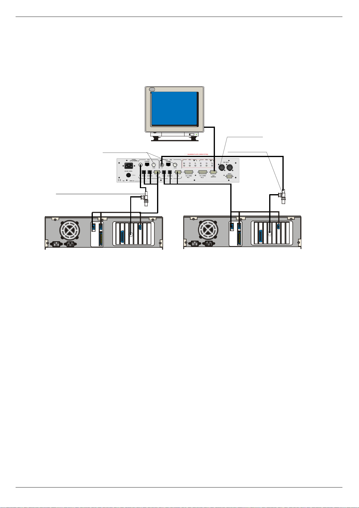
418 &RQQHFWL RQV#0#%1&
Figu res 1-1, 1-2, and 1-3 on page 1-4 show how to connect the Séance box to the
consol e an d the com pu t e rs ru n nin g S AM .
7R#UHPRWH#3.1
83#RKP#WHUPLQDWLRQ
(WKHUQHW#WHUPLQDWHG #DW#3&#HQG
0RXVH
.H\ERDUG
9*$
(WKHUQHW#WHUPLQDWHG#DW#3&#HQG
0RXVH
.H\ERDUG
9*$
3&4#ZLWK#(WKHUQHW#FDUG 3&5#ZLWK#(WKHUQHW#FDUG
FIG 1-1. Séance rear panel connections for BNC
41814 (WKHUQH W#0#%1&
The Séance box communicates with the PCs over a 10Base-2 Ethernet connection
via a 50 ohm BNC cable terminated at each end with a 50 ohm terminator. The
Séance box has two BNC connectors for each PC inter face, which are wired in parallel in side. A 50 ohm terminator plugs into the BNC socket labelled TERM INA TOR
and th e Ethernet cable plugs into the BNC socket labelled C O MPUTER. A terminator and T-piece are used to connect the Ethernet cable to the PC.
Séanc e Interface 7975 Revision SE2005-2
Page 7
Introduction 1-3
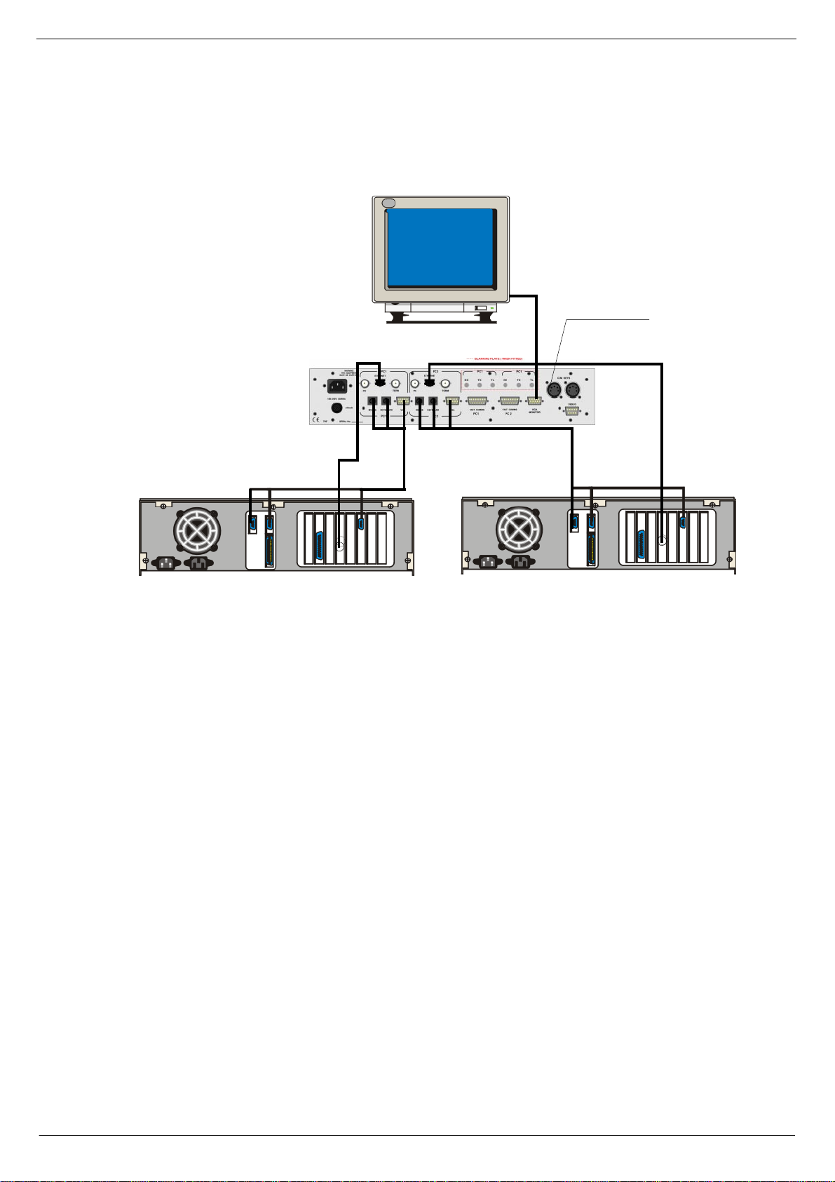
&RQQHFWLR QV#0#5-78
7R #UHPRWH# 3.1
0RXVH
.H\ERDUG
9*$
3&4#ZLWK#(WKHUQHW#FDUG 3&5#ZLWK#(WKHUQHW#FDUG
FIG 1-2. Séance rear pa nel connections for RJ45
41815 (WKHUQHW#0#5-78
The Seance box can also communicate with the PC via an RJ45 connector depending
on the type of Ethernet-card in the computer. The Séance box has two RJ45 connectors, one for ea ch PC interface. These connectors should be connected directly into
a comp uter. It is also po ss ib l e t o c onn ec t the R J45 soc k e ts t o a hu b. For d eta il s a bo ut
this , contact CAD AC technical support.
0RXVH
.H\ERDUG
9*$
Revision SE2005-2 Séance Interface 7975
Page 8

1-4 Introduction
FIG 1-3. Séance front panel connections - BNC and RJ45
41816 0RXVH
Each PC has a ‘one-to-one’ PS2 mouse cable, which co nnects between the PC’s
mouse port and the mouse connector on the rear panel of the Séance box. The
mouse plugs into the mouse connector on the front panel of the Séance box.
41817 .H\ERDUG
Each PC h as a ‘ o ne-o ne ’ PS2 k e yboa r d c ab le , whi ch co nn ects be tw ee n t he PC ’ s k e yboard port and the keyboard connector on the rear panel of the Séance box. The keyboar d connects into the keyboard connector on the fr ont panel of the Séance box.
Converters are supplied to connect to a 5-pin DIN keyboard and 5-pin DIN connectors
on the PC.
41818 9*$
Each PC has a VGA cable connected between the computer’s VGA output and the
corresponding VGA connector on the rear panel of the Séance box. The VGA monitor
cable plug s int o the VGA con ne c tor.
0RXVH .H\ERDUG
41819 &&0#NH\V
The Séance interface reads the PC2 switch on the console’s CCM. The 5-pin XLR
connectors are paralleled together inside the Séance. A ‘female-female, one-one cable ’ conn ects to the k eys conne ctor on th e CCM an d the ot her ca n be us ed to c onnec t
to remote PREV and NEXT keys if required.
4181: )DVW#FRSSHU#FRPPXQLFDWLRQV
CADAC’s 15 way “f ast copper communications” cables are used to connect between
the Séance box’s fast comms connectors and the CCM. The cable plugged into Fast
comms PC1 on the Séance box must be connected to PC1 on the CCM.
4181; 'HEXJ#SRUW
The debug port is standard PC 9-pin serial port that can be used to access the
Séance box’s computer.
4181< 0DLQV
The Séance box has a universal power supply and can be connected to AC mains 100
– 240V, 50/60Hz.
418143 )XVH
20mm 315mA fuse
Séanc e Interface 7975 Revision SE2005-2
Page 9

Introduction 1-5
419 &RPP XQ LFD WL RQV #VHWXS
Séance and SAM communicate over an Ethernet network using the TCP/IP protocol.
In ord er f or a succe ssfu l con necti on t o be mad e, each PC runn ing SAM ne eds to kno w
an IP address and port number of the Séance box and the Séance needs to know the
IP addr ess an d port numb er f or ea ch comput er runn ing S AM. Ind ivid ual IP a ddress es
must be different but the SAM port can be the same for each computer on the network.
The suggested settings are:
Séance IP address:194.222.033.010
Séance port:1111
PC1 IP address:194.222.033.011
PC2 IP address:194.222.033.012
SAM port:1112
SAM SETUP port:1113
Séance SETUP port:1114
When a Séa nce bo x i s ship ped fro m the f act ory the abo v e sett ing s are pr e-set . Matc hing settings are copied onto the PC the first time SAM is installed. If these values are
to be used for an installati on, the only settings that need to be ad justed are PC1 and
PC2’s IP address on each PC. See 2.6.1 and 2.6.2 for det ails (Note: This procedure
needs be carried out before you continue.)
In order to have SA M communicating with a consol e, the network interface needs to
be set up, see below:
41: 6$0#VHW0XS=
1. SAM’s PC needs TCP/IP networking installed and an IP address allocated.
2. SAM needs to know the IP ad dress of the Séance box (pre-set to
3. 194.222.33.10)
4. SAM needs to know the Séan ce bo x’s port numbe r (pre-set to 1111)
5. SAM needs to be given a port number ( pre-set to 1112)
41; 6pDQFH#VHW0XS=
1. Séance needs to be given a port number (pre-set to 1111)
2. Séance needs to know PC1’s IP address (pre-set to 194.222.33.11)
3. Séance needs to know PC2’s IP address (pre-set to 194.222.33.12)
4. Séance needs to know SAM’s port number (pre-set to 1112)
The set -up proced ure is di ff erent depe ndin g on which opera tin g syst em i s used on the
PC. SAM can run under Windows 95, Windows 98 or Windows NT. Each operating
system has it’s own set-up guide in the following pages.
41< 3RZHULQJ0XS#VHTXHQFH#RI#3&V
Always use the following pr ocedure:
Power-up cons o le
■■■■
Select PC1 on the CCM and power up the first computer. Wait until the PC1
■■■■
comput er has completed its boot-up routine, then. ..
Switch to PC2 on the CCM and power-up the second comput er and wait until it
■■■■
has completed its boot-up routine.
Power-up the Seance-box.
■■■■
Once both computers have booted correctly, they should allow the keyboard and
monitor to be switched back and forth without problems.
If the overall cable length for the keyboard and monitor are very long (greater than
5m), it may be necessary to use a keyboard and a monitor booster unit to retain keyboard reliability and clean monitor display.
Revision SE2005-2 Séance Interface 7975
Page 10

1-6 Introduction
Séanc e Interface 7975 Revision SE2005-2
Page 11
PC Setup 2-1
5 3HWXS
This section contains information about setting up the computer for network operation,
installing network adapter and setting up SAM.
514 6HWWLQJ#XS#D#QHWZRUN#FR QQHFWLRQ#IRU#:LQGRZV#
17
The network is set up in the NETWORK folder in the control panel. You open the network folder by:
1. Click on the Windows® START button on the task bar.
2. Point to the Settings box.
3. Click on the control panel.
4. Double click the network folder.
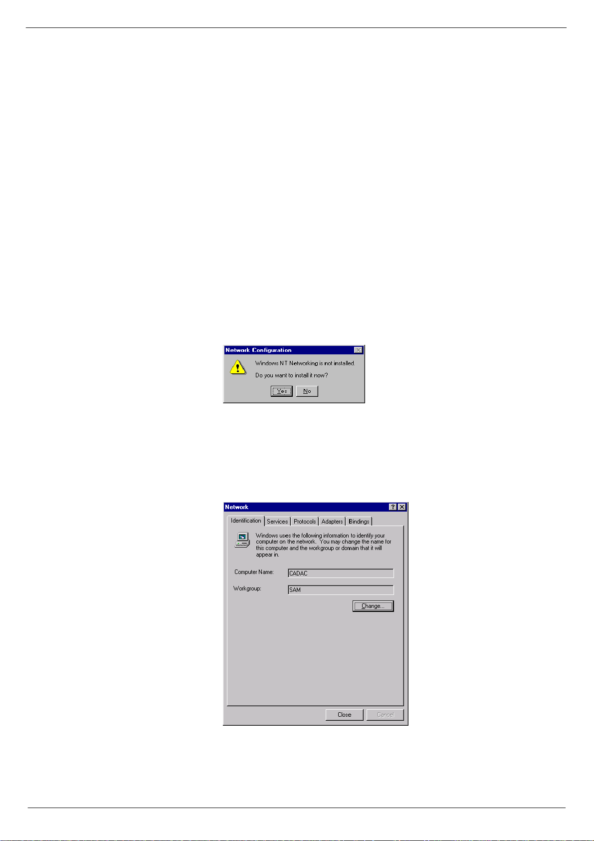
If networking has no t bee n i nst all ed , t he di a lo gu e bo x, sh o wn i n fi gu re 2-1 , wi ll be displayed. Click the Yes box and follow the procedure in 2.2.
FIG 2-1. Network not installed
If the network dialogue box is displ ayed as shown in figure 2-2, networking is already
installed and the settings should be checked as described in 2.3.
FIG 2-2. Network dialogue
Revision SE2005-2 Séance Interface 7975
Page 12
2-2 PC Setup
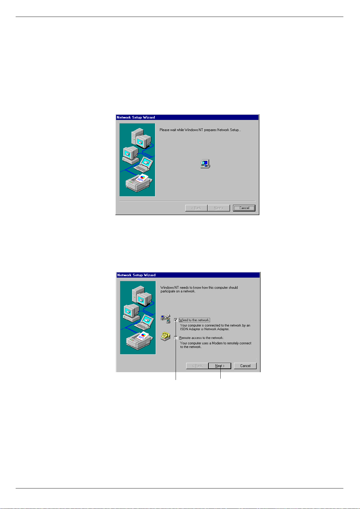
515 ,QVWD OOLQ J #17#QHWZ RUNLQJ#
If you click the network icon in the control panel and NT networking has not been instal led, the netwo rk install wizard will run. This wizard will display the step by step
guide sho wn by fig ure 2- 3 th rough t o fi gure 2 -12 and 2 -13 th roug h to fi gur e 2-17 . Most
of the steps require the default setting to work with the Séance box.
3OHDVH#ZDLW111
FIG 2-3. Step 1 - Network setup and step 2 Network type (below).
0DNH#VXUH#WKH#RSWLRQ
&OLFN#1H[W
:LUHG#WR#1HWZRUN
LV#FKHFNHG
Séanc e Interface 7975 Revision SE2005-2
Page 13

PC Setup 2-3
&OLFN#6WDUW#VHDUFK
FIG 2-4. Step 3 and 4 - Selecting network adapter
0DNH#VXUH#7&32,3#SURWRFRO#LV#FKHFNHG
FIG 2-5. Step 5 - Network
prot oc ol .
&OLFN#1H[W
&OLFN#1H[W
Revision SE2005-2 Séance Interface 7975
Page 14

2-4 PC Setup
&OLFN#1H[W
FIG 2-6. Step 6 - Network services.
&OLFN#1H[W
FIG 2-7. Step 7 - Ready to install
&OLFN#1R
FIG 2-8. Step 8 - DHCP
Séanc e Interface 7975 Revision SE2005-2
Page 15

PC Setup 2-5
&OLFN#1H[W
FIG 2-9. Step 9 - Network bindings
&OLFN#1H[W
FIG 2- 10. Step 10 - Install the network and step 11 - Internet Host Name
&OLFN#1R
Revision SE2005-2 Séance Interface 7975
Page 16

2-6 PC Setup
&OLFN#1R
IG 2-11. Step 12 - DHCP client
FIG 2-12. Step 13 - Finished and step 14 - Restart your computer
Continue through the section Setting up NT networking to check the adapter type and
to set-up the TCP/IP protocol.
&OLFN#)LQLVK
&OLFN#1R
Séanc e Interface 7975 Revision SE2005-2
Page 17

PC Setup 2-7
516 6HWWLQJ#XS#17#QHWZ RUNLQJ
For SAM r un ning on a W ind o ws NT com pute r to co mm un ic at e wi t h a S éan ce bo x t h e
fo llowing need to be installed.
An Ethernet Adapter.
■■■■
TCP/IP protocol.
■■■■
Click the Adapter s tab. If the computers network adapter is not present click the Add
but ton to display the NT adapter dialogue as shown in fig 2-13.
&OLFN#$GDSWHUV
&OLFN#$GG#WR#GLVSOD\#WKH#17#DGDSWHU#GLDORJXH#ER[
FIG 2-13. NT network adapter
Revision SE2005-2 Séance Interface 7975
Page 18

2-8 PC Setup
IG 2-14. NT network adapter dialogue
FIG 2-15. NT network pr otocols
6HOHFW#DGDSWHU
Select t he ad ap t er f r om t he li st ( o r us e a di sk su ppli ed b y t he ad ap te r’s manuf ac tu rer )
and click OK.
Click the Protocols tab. If TCP/IP protocols is not present click the Add button to display the add protocols page shown in fig 2-16.
Click on TCP/IP protocol followed by OK.
&OLFN#2.
&OLFN#3URWRFROV
&OLFN#7&32,3
SURWRFROV
&OLFN#$GG#WR#DGG#SURWRFRO
Séanc e Interface 7975 Revision SE2005-2
&OLFN#2.
Page 19

PC Setup 2-9
&OLFN#WR#DGG#SURWRFRO
FIG 2-16. NT network protocols dialogue
&OLFN#2.
&OLFN#6SHFLI\#DQ
,30DGGUHVV
(QWHU#3&¶V#,30DGGUHVV#DQG
6XEQHW#PDVN
&OLFN#2.
FIG 2-17. NT TCP/IP properties
Set up the IP address by clicking on TCP/IP protocol, see fig 2-15 followed by the
properties button, to display the dialogue box in fig 2-17. Click on Specify an IP addres s and enter the PC ’s IP address and Subnet mask.
W ARNI NG: D o no t ad d le adin g ze ros i nt o th e IP a dd res s a nd S ubne t mas k f i elds ( i. e .
input 194.222.33.11 not 194.222.033.011). If this is not observed, the computer will
not communicate.
Revision SE2005-2 Séance Interface 7975
Page 20

2-10 PC Setup
517 6HWWLQJ#XS#D#QHWZ RUN#FR QQ HFWLR Q#IRU#:LQGRZV#
<82<;
The n etwork is set up in the NETWORK folder in the con trol panel. You can open the
network folder by:
1. Click on the Windows® START button on the task bar.
2. Point to the Settings box.
3. Click on the Control panel.
4. Double clic k the Network folder.
Figure 2-18 shows the minimum network components required to communicate with
the Séance box. If t hese components are missing, they should be installed. If this is
the case, you may need the Windows 95/98 system disk. There may be other components displayed in the Network window, depending on how the network was installed,
but the essential components are:
An Ethernet Adapter 10Base2 (not supplied by CADAC).
■■■■
Figu re 2-18 shows a 3COM Ethernet adapter , this must match the type of ne twork
card in the computer and may have a different description.
TCP/IP protocol.
■■■■
FIG 2-18. Network setting s dialogue box
FIG 2-18. Network settings dialogue box
Séanc e Interface 7975 Revision SE2005-2
Page 21

PC Setup 2-11
518 ,QVWDOOLQJ#D#QHWZRUN#DGDSWHU#LQ#:LQGRZV#<82<;
There are a number of ways to install a network adapter. The procedure below installs
an adapter from the network settings dialogue, see fig 2-18.
1. Cl ick Add, see fig 2-19, to bring up the Select Network components dialogue box
shown in fig 2 -19 .
2. Click Adapter to bring up the se lect network adapter dialogue shown in figure
fig 2-19.
3. Click on the Manufacturer of the network adapter
4. Click on the ty pe of Network adapter
5. Click the OK b utton
&OLFN#$GG#WR
RSHQ#GLDORJXH#ER[
&OLFN#PDQXIDFWXUHU &OLFN#W\SH
FIG 2-19 . Sele cti ng netw ork c omponen t and selec ting netwo rk ad apte rs.
Revision SE2005-2 Séance Interface 7975
&OLFN#2.
Page 22

2-12 PC Setup
519 ,QVWD OOLQ J #7&32,3#SURWRFRO#LQ#:LQGRZV#<82<;
1. Click the Add button in the network dialog ue. This brings up the Select Network
component type dialogue as shown in fig 2-20.
2. Click Protocol, see fig 2-20.
3. Click Add to display the Select Network Protocol dialogue as shown in
4. Click Microsoft.
5. Double click TCP/IP.
FIG 2-20. Select Network protoc ols dialogue
51914 6HWWLQJ#XS#7&32,3
An IP address need s to be allocated to each node on the network. CADAC suggests
using 194.222.33.11 for PC1 and 194.222.33.12 for PC2.
&OLFN#0LFURVRIW
'RXEOH0FOLFN#7&32,3
Séanc e Interface 7975 Revision SE2005-2
Page 23

PC Setup 2-13
51915 7R#VHW#WKH#7&32,3#SURSHUWLHV#IRU#WKH#3&=
1. Click TCP/IP in the Network settings dialogue, see fig 2-18.
2. Click the Properties button to open the TCP/IP Properties dialogue as shown in
fig 2-21.
3. Click Specify an address
4. E nter the IP addr ess into the IP address field (194.222.33.11 for PC1 and
194.222.33.12 for PC2).
5. Enter 255.255.255.0 into the Subnet mask field
6. Click on the WIN S configuration
7. Click Disable WINS configuration
8. Click on the DNS configuration
9. Click Disable DNS configuration
FIG 2-21. TCP/IP properties dialogue
WARNING:
Do not add leading ze ros into the IP address and Subnet mask fields (i.e. input
194.2 22.33.11 not 194.222.033.011). If this is not observed, the computer will not
communicate.
194 . 222. 33 . 11
Revision SE2005-2 Séance Interface 7975
Page 24

2-14 PC Setup
51: 6HWWLQJ#XS#6$ 0
SAM’s communications will be set up when the communications are first opened.
1. Click on the Comms item on the menu bar
2. Click on Open comms; to display the dialogue box shown in fig 2-22.
3. T he IP address allocated to the Séance box should be typed into the Séance IP
Address box.
4. SAM’s port number should be entered into the Local Port box
5. Séance’s p ort number should be entered into the Remote Port box.
6. The ‘Use USB port’ check box shoul d NOT be ticked.
The IP address of the computer running SAM is shown for information and cannot be
change d he r e.
FIG 2-22. SAM’s Network
settings dialogue
51; 6$0·V#,FRQV
When communication has bee n established between SAM and the Séance box, the
SAM present LED will light on the Séance box and a tic k will appear in the Séance
icon in SAM.
SAM’s communication is open and SAM/Séance are communicating
SAM’s communication is open but SAM/Séance are not
communicating (red cross)
SAM’s communications is not open (blue cross)
SAM’s communication is open and Séance/Console
are communicating
SAM’s communication is open but Séance/Console are not
communicating (red cross)
SAM’s communications is not open (blue cross)
WARNING:
Do not add leading zeros into the IP address and Subnet mask fields (i.e. input
194. 222.33.11 not 194.222.033.011). If this i s not observed, the computer will not
communicate.
Séanc e Interface 7975 Revision SE2005-2
Page 25

Séance 3-1
6 6pDQFH
This se ction contains information about th e Séance setup and various user options
for the Séance interface.
614 %RRW#XS#VHTXHQFH#GL VSOD\V
When the Séance box is powered up it should run through a boot up sequence and
automatically run th e Séance program. Figure 3-1 shows a block diagram of the
screens available during power up. There are a number of debug facilities available in
the util screen which is accessed by pressing and holding the right hand key during
power-up or when the Séance program restarts.
Power on sequence
Revert to previous version
Seance PCTCP Config
SEANCE BROWSE DOS REMOTE util
Revert to previous configuration
No Yes
Revert to previous pctcp.ini
No Yes
Revert to previous s e ance.exe
No Yes
Select
Enter selection
Messages
only show if
Seance version is earlier than 34267
Message
only shows if
no Ethernet
connection
exists
CMOS check
Starting Autoexec.bat
Loading Ethernet driver
Press key to select Ethernet I/F*
Comp BNC HUB NONE
Loading packet driver
Starting Seance Util
Executing remserve
Exiting to dos
FIG 3-1 . Boot up sequence
615 87,/#VFUHHQ
The UTIL screen allows the user to go back to the previous version of Séance program, Séance options or TCP/IP options if the updating process fails.
Pressi ng th e Séa nce k e y wi ll pr ompt to r ev e rt t o the l as t saved vers io n of the Sé an ce
progr a m. O nce r everted the ne w er v e rsi on is saved as the l a st v e rs ion s o t h e tw o can
be togg led be twee n usin g thi s functi on. S imil arly the Séanc e option s can re v ert to the
previous version as can the TCP/IP set-up (the Séance box’s IP address).
Revision SE2005-2 Séance Interface 7975
Page 26

3-2 Séance
616 5HPVHU YH#PRGH
Remserve mode allows ac cess to the Séance’s disk via the debug port on the rear
panel and a COM port on the PC. You need a ’NULL MODEM’ cable to establish communications.
617 5HPRWH#PRGH
Remote mode allows access to DOS on the Séance box via the debug port on the
rear panel and a COM port on the PC. You need a ’NULL MODEM’ cable and a terminal emulation program to establish communications.
618 6pDQFH#'LVSOD\#7UHH
Figure 3-2 shows a block diagram of the screens available in the séance program.
There are four screen types in the Sé ance program, each selectab le from the main
menu. They are the option scr eens, error s c reens, status screens and version
screens.
Restart the program
Options
Seance ip address =194.222.033.010
exit prev next edit
Options edit
Seance ip address 194.222.033.010
quit cursor - + save
Save options
no options yes
Save new options
Main
CADA C Seance :Console = FTYPE Pc1 BNC
Restart Status Options Version Error
Seance version
Seance : 1.02 Nov 18 1999 12:11:58
quit version
Seance config : 10
quit version
CCM version
CCM : 1.10
quit version
Status
cue = 1.0 DXS
quit dynamic
errors
SAM : ethernet message not received
quit more next
extended error
routine = check_ethernet_message ()
quit next
dynamic
200P
quit
Save the options
FIG 3-2. Séance screens
Séanc e Interface 7975 Revision SE2005-2
Page 27

Séance 3-3
619 0DLQ#VFUHHQ
The main screen display the console type the Séance is set to and the state of the
PC1/PC2 s w itc h. It al so disp lays BNC or RJ4 5 c onnec t io n (r j45 lo w er case me an s n o
connection, RJ45 upper case means connecting).
61: 2SWLRQV#VFUHHQV
The option screens allow the user to modify the Séance box’s configuration.
61; 9HUVL RQ#VFUHHQV
The v ersi on scr eens displa y t he v ers ion of soft ware r unni ng in the séan ce bo x a nd the
CCM.
61< (UURU#VFUHHQV
The error screens display information about error conditions occurring in the Séance
software. The main error screen displays a description of the error. Pressing the
“more”-button w ill display the software routine that the reported the error.
6143 6WDWXV#VFUHHQV
There are two status screens which can be used to feed back the st ate of the séance
software for debugging purposes. The main status screen displays the number of the
currently selected cue along with a dynamic code. (If Comms is active the screen will
show SAM/Setup/CCM.)
D:dynamic
A:auto start
S:step time
X:cross fade
M:MIDI sequence
Pressing the dynamic key displays the dynamic stat us screen which sh ows the cue
number and code of any dynamic that is active.
The codes are as follows:
S:stopped
I: prepared
T:started
R:recording
P:playing
p:pause play
E:stopped record
A:star t pl ay
C:created
N:play now
Y:play error
D:record error
?:unkno wn state
Revision SE2005-2 Séance Interface 7975
Page 28

3-4 Séance
6144 6pDQFH#%R[ #VHW0XS
FIG 3-3. Main display
The Séance box is set up via the options menu set. This is acc essed from the ma in
screen by pressing the options key as sh own in figure 3-3. Each option is displayed
one at a time; figure 3-4 shows the first option available. Using the next/prev keys accesses other options. Pressing the edit key can alter the option or bring up a separate
editin g s cr ee n dep en di ng on t he o pt ion t ype . An y o pti on s ch an ge d wi ll not be ap plie d
unti l the opti ons s cree ns are e xite d. I f an o pti on ha s cha nged then a sav e c onfi rmati on
screen is displayed, see figure 3-5.
FIG 3-4 . O ptions screen
FIG 3-5. Opti on s save c onf i rmat i ons scr e en
FIG 3-6. Number edit screen
Séanc e Interface 7975 Revision SE2005-2
Page 29

Séance 3-5
6145 7R#VHW#WKH#6pDQFH#ER[·V#RSWLRQ V =
1. Pr es s t he op tio ns k ey in the main men u , s ee figu r e 3 -3. Th e fi r st op tion di sp layed
is the Séance IP address.
2. To change this option, press the edit key, see figure 3-4, which will display the
number ed it sc r ee n as show n in fig ur e 3- 6.
3. The IP address can be edited by pressing the cursor key to move the cursor to
the n umber that requires changing and using the + or – keys to alter the nu mber.
4. Pressing the save key will log the changed number and exit the edit screen but
this will not be saved until the options screen is exited. Changing the Séance IP
address will cause the program to re-start.
5. Use the quit key to exit the number edit screen and restore the original number.
6146 6pDQFH#2SWLRQV
There are three levels of options within the Séance. These are:
Operator:Séance set-up options
■■■■
Debug:Various debugging options; only for use by CADAC-personnel.
■■■■
CADAC:System options; only for use by CADAC-personnel.
■■■■
The option called ‘level clearance’ must be s et to the correct level in o rder to display
and cha nge th e option s. CAD AC le ve l can see all opti ons . Deb ug le ve l can se e deb ug
and operator options but not CADAC options. Operator level cannot see either Debug
or CADAC options. The operator options are described below, while the Debug and
CADAC options are described in 4 Technical section. The options settings are dis-
played with the default value in bold type.
Revision SE2005-2 Séance Interface 7975
Page 30

3-6 Séance
6147 2SHUDWRU#RSWLRQV
Séance IP address
This is the Séance box’s IP address. It must match the séance IP address setting in
SAM’s COMMS/Network settings dialogue.
Level clearance
Console
The Séance asks for the console type wh en the séance box or console powers up or
is reset. With this option set to AUTO the Séance will automatically set itself to work
with the reported console. The console type can be manually set to over-ride this setting.
PC1 IP address
This is the IP address of PC1. It must match the setting in PC1’s Windows network
dialogue.
PC1 SAM port
This is the SAM port for PC1. It must match the setting in SAM’s COMMS/Network
settings dialogue on PC1.
PC1 Séance port
This is the Séance box’s port. It must match the Séance port setting in SAM’s COMMS/Network settings dialogue on PC1.
PC2 IP address
This is the IP address of PC2. It must match the setting in PC2’s Windows network
dialogue.
PC2 SAM port
This is the SAM port for PC2. It must match the setting in SAM’s COMMS/Network
settings dialogue on PC2.
194.222.033.010
Operator
Auto
194.222.033.01
01112
01111
194.222.033.012
01112
/Debug/CADAC
/M-Type/F-Type/J-Type/Concert
1
PC2 Séance port
This is the Séance box’s port. It must match the Séance port setting in SAM’s COMMS/Network settings dialogue on PC2.
SAM SETUP PORT
This is the SAM SETUP port. It must match the settings in the SAM SETUP’s Network
settings dialo g ue.
SÉANCE SETUP PORT
This is the SÉANCE setup port. It must match the settings in the SAM SETUP’s Network settings dialogue.
01111
01113
01114
Séanc e Interface 7975 Revision SE2005-2
Page 31

Séance 3-7
6148 6pDQFH#LQGLFDWRUV
614814 0HVVDJH#/('
The yellow message LED will flash briefly when an Ethernet message arrives for the
Séance box.
614815 $FWLYLW\#/('
The green activity LED indicates that there are messages on the Ethernet interface.
614816 &&0#3UHVHQW#/('
The green SAM present LED will light when Séance/Console communications are
present.
614817 &&0#(UURU#/('
The red error led will light solidly when Séan ce/Console communications are not
present. It will flash when a Console related error ha s occurred.
614818 6$0#3UHVHQW#/('
The green SAM present LED will light when SAM/Séance communications are
present.
614819 6$0#(UURU#/('
The red erro r led w ill light soli dly wh en SAM/ Séanc e comm unic ati ons ar e not p res ent.
It will flash when a SAM or Ethernet error has occurred.
61481: 3RZHU#/('
The red power LED indicates that +5Volts is present on the Séance PCB.
61481; 3&5#/('
The yellow PC2 LED is alight when the console is set to PC2.
Revision SE2005-2 Séance Interface 7975
Page 32

3-8 Séance
6149 8SGDWLQJ#WKH#6pDQFH#SURJUDP#+YHUVLRQ#4134#
RQZDUGV,
To updat e the Séance program, the Séan ce box needs to be sw itched ON and con nected to a computer, which, of course, also has to be switched ON. Updating of the
Seance software is done via the SAM utility, SAM SETUP.
The file required for updating is called Seance.exe.
Sinc e the introduction of Seance, two types of processors have been used. The orig-
inal design used an Arcom, but has since been changed to Hitex. This change occurred from and inclu s ive of serial number 34268 (Aug. 2001).
If you have received a software update on a CD-ROM, you will, in the Seance folder,
find s eparate sub-folders for Arcom and Hitex.
If you hav e downloaded the latest version o f the software from the CADAC website,
Seance.exe will be found in the Seance download zip-file. Note the location of the
downloaded and unzipped files on your PC.
If Seance.exe has been sent to you as a separate file, note the location of the file on
your PC.
Update the Séance program from SAM SETUP by performing the following steps:
1. Run the utility SAM SETUP.
2. In the SAM SE TUP main menu click on Séance.
3. Click on Open Port.
4. In the Network Settings window, make sure that the Séance IP-address is identical to the one specified in 1.6 Communications setup. Make sure that the port
setting for the Local port is the same as for the SAM SETUP port and that the
‘Use USB port’ option in the Network Settings dialog box is left unchecked.
5. Make sure that the port setting for the remote port is identical to the one for the
Séance SETUP port (see 1.6 Communications setup).
6. Click OK.
7. In the SAM SETUP main menu, click on Séance again.
7.1 Click on Update S eance
7.2 Click Browse
7.3 Find the file Seance.exe (by browsing the CD-ROM; browsing your harddisk
drive; browsing a floppy disk)
7.4 Select the file Seance.exe
7.5 Click “Open”
7.6 Click “Update”
The so ftware should load and overwrite the existing Seance software.
8. W hen Update has transferred all the files, press the Version bu tton under the display window on the Séance box. Check that the display shows correct version
number, rele ase date and time for update.
If the update has been successful, the Séance will restart using the new executable.
It is possib le t o do wnloa d oth er fil es to the S éanc e box i n thi s wa y b y us ing the Upd ate
files option in the file menu.
WARNING:
194. 222.033.011 should be typed 194.222.33.11 ). If this is not observed, the
computer will not communicate.
Séanc e Interface 7975 Revision SE2005-2
Do not add leading zeros into the IP-address (i.e. the address
Page 33

Technical section 4-1
7 7HFKQLFDO#VHFWLRQ
This section contains technical information regarding various user options and settings.
714 'HEXJ#RSWLRQV#
The following is a description of the debug options available in the Séance box. They
are only displayed if the level clearance option is se t to debug or CADA C. If the level
clear anc e is se t to ope ra tor th en t hese o ptions wil l not be av ail ab le. The y are p rimar ily
used to log Ethernet and CCM messages for development and fault finding purposes.
Altering these options can affect the operation of the Séance box.
VGA Screen present
This option indicates that the test VGA card is fitted.
cgc screen debug
Direction of messages to/from the CCM that are logged if cgc logging is enab led.
ether debug
Direction of messages to/from the PC that are logged if ethernet logging is enabled.
cgc screen enable
This opti on e na ble s lo gg in g to t he sc reen a nd def in es ho w t he l og ge d CCM messa ge
data is interpreted.
Ether screen enable
This option enables logging to the screen and defines how the logged Ethernet message data is interpreted.
logf ile always open
If the opt ion is on then th e logg ing sof twa re does not open/ clo se the lo gfile ev ery time
it accesse s it.
cgc file enable
This option enables logging to the logfile and defines how the logged CCM message
data is interpreted.
Ether file enable
This option enables logging to the logfile and defines how the logged Ethernet message data is interpreted.
input/
/On
Off
input/
both
off/
off
status/interpret/hex dump/raw data
off/
off/
/output
both
/output
status /interpret/hex dump/raw data
status/interpret/hex dump/raw data
off/
/on
status/interpret/hex dump/raw data
Performanc e Scr e e n
This option enables the real time performance screen.
Error messages
This option enables/disables error messages.
Main debug file
Enab le reading of filter file
Dynamic debug file
This option enables logging of dynamic messages and defines the logfile name.
Debug file name
Message Filter filename
Revision SE2005-2 Séance Interface 7975
on
off/
/on
off
/on
off
d:\dynamic.log
-séance.dbg
Page 34

4-2 Techni c al sectio n
715 &$'$&#RSWLRQV
The following is a description of the CADAC options available in the Séance box. They
are only displayed if the level clearance option is set to CADAC. If the level clearance
is set to op erator or deb ug th en th es e op tio ns wil l n ot be a v ail able. They ar e p rimar il y
used to set the Séance program to work with the hardware.
WARNING! Altering these options can cause the Séance box
to stop functioning
.
CS8900 flag
This option indicates the Ethernet chip-set is Cryst al 8900
Maximum message size
This option defines the maximum Ethernet message block size.
IRQ number
F ast comms interface irq number.
Fast comms i/ o po rt
This is the i/o base address for the séance i/o ports.
Screen timeout
This is the number of seconds before the LCD backlight power saving times-out.
Print er po rt debug
This option enables various system timing signals to appear on the p rinter port.
Ghostly presence
This enables next and previous cue recalls.
Poltergeist presence
This enables test dummy ethernet messages.
Keep alive
This option enables the keep alive messages between SAM and Séance, which are
used to light the present indicators.
on/off
5
off/
15000
on
off/
off/
$382
on
on
off/
10000
on
Séanc e Interface 7975 Revision SE2005-2
Page 35

Technical section 4-3
716 ,QWHUQDO#RSWLRQV/#VHWWLQJV#DQG #WHVW#SRLQWV
71614 &RQQHFWRUV
CN10 Connector for the optional optical comms board.
CN11 Connector for the Fast copper comms Debug handset.
71615 )XVH
20mm 315mA
71616 3&%#-XPSHU V
J17 Connects hold-up capacitor on the keyboard supply line when fitted. (fitted)
J18 Connects hold-up capacitor on the mouse supply line when fitted. (fitted)
J19 Select PC irq4 for fast copper comms
J20 Select PC irq5 for fast copper comms. (fitted)
J24 Available for software option
J26 A vailable for software option
J30 Heart beat enable build 2,3
J31 Heart beat enable build 1 (not fitted)
71617 3&%#PRXQWHG#/('1
LD1 currently unused
LD2 Séance background LED, flashes once a second when the Séance program is
running.
LD3 indicates presence of the Ethernet –9v supply when solidly lit.
P1 Display view angle pot.
SW1 Reset switch (not fitted).
71618 7HVW #SRLQWV1
TP1: Ethernet –9V supply return
TP2: System 0V
TP3: System 0V
TP4: F ast comms interrupt
TP5: PC interrupts
TP6: Swm2
TP7: Swm1
TP8: Frame
TP9: Fast comms receive
TP10: Fast comms transmit
TP11: Fast comms Timeline in
Revision SE2005-2 Séance Interface 7975
Page 36

4-4 Techni c al sectio n
Séanc e Interface 7975 Revision SE2005-2
Page 37

,QGH[
A
Activity LED 3-7
B
Boot up sequence 3-1
C
CCM Keys 1-3
CCMPres ent LED 3-7
cgc file enable 4-1
cgc screen debug 4-1
cgc screen enable 4-1
Connectors 4-3
CS8900 flag 4-2
INDEX-1
D
Debug file name 4-1
Debug options 4-1
Debug port 1-3
Display Tree 3-2
Dynamic debug file 4-1
E
Error messages 4-1
error screens 3-2
ether debug 4-1
Ether file enable 4-1
Ether screen enable 4-1
Ethernet 1-4
F
Fast c omms i/o port 4-2
fast copper communications 1-1
Fuse 4-3
G
Ghostly presence 4-2
I
Installing a network adapter in Wind ows 95/98 2-11
Installing NT networ king 2-2
Installing TCP/IP protocol in Windows 95/98 2-12
IRQ number 4-2
K
Keep aliv e 4- 2
keyboard 1-1
Revision SE2005-2 Séance Interface 7975
Page 38

L
Level clearance 3-6
level clearance 3-5
logfile always open 4- 1
M
Main debug file 4-1
Main screen 3-2
mains 1-1
mains fuse 1-1
Maximum message size 4-2
message LED 3-7
mouse 1-2
O
operator options 3-5
Options screen 3-4
P
INDEX-2
PC1 IP address 1-4
PC1 SAM port 3-6
PC1 SEANCE port 3-6
PC1 Séance port 3-6
PC2 IP address 1-4, 3-6
PC2 LED 3-7
PC2 SAM port 3-6
PC2 SEANCE port 3-6
PC2 Séance port 3-6
PCB Jumpers 4-3
PCB mounted LED 4-3
performance screen 4-1
Poltergeist presence 4-2
Power LED 3-7
Printe r por t de bu g 4- 2
R
Remote mode 3-2
Remser v e mode 3-1
restar t 3-8
S
SAM Error LED 3-7
SAM present LED 3-7
SAM SETUP 1-4
SAM_s Icons 2-14
SAM’s Icons 2-14
Screen timeout 4-2
Seance IP address 3-6
Séance IP-address 3-8
Séance SETUP 1-4
Setting up a network connection for Windows 95/98 2-10
Setting up a network connections for Windows NT 2-1
Setting up NT networking 2-7
status screens 3-2
T
TCP/I P properties 2-13
terminator 1-2
test points 4-3
Revision SE2005-2 Séance Interface 7975
Page 39

U
util screen 3-1
V
version screens 3-2
VGA 1-3
VGA Screen present 4-1
INDEX-3
Revision SE2005-2 Séance Interface 7975
 Loading...