

Page 1

#
*g8;2'
Audio Mixing Console
-056#..#6+10#n#95'4#1#07#.
Page 2

CADAC Electronics
One New Street
Luton
Bedfordshire
LU1 5DX
England
Tel +44 (0) 1582 404 202
Fax +44 (0) 1582 412 799
email: info@cadac-sound.com
While ev er y eff or t ha s b ee n ta ke n t o ensu re the a ccu racy o f th e c onte nt s in thi s m an ua l, C AD AC Live P erf orma nc e A u dio Mix in g Con s ol es are
subject to continuous development, hence the information in this manual may not reflect the latest product updates.
© Copyright CADAC Electronics plc. 2005.
Page 3

Table of Contents iii
7DEOH#RI#&RQWHQWV
6(&7,21 3 $*(
*HQHUDO#3UHFDXWLRQV 111111111111111111111111111111111111111111111111#Y
,QWURGXFWLRQ111111111111111111111111111111111111111111111111111111111111#YLL
4 &RQQHFWLQJ#WKH#PL[HU#V\VWHPV1111111111111111111111111111 #404
1.1 Console modularity ....................................................................... 1-1
1.2 Frame rear connections................................................................1-1
1.3 Connect Power supply systems.................................................... 1-2
1.4 Connecting the console frames .................................................. 1-11
1.5 Connect Console Automation System ........................................ 1-14
1.6 Connect main frame facilities from modules to frame.................1-19
1.7 Switching ON .. .... ............... .... .... .... ............... .... .... .... ............... ... 1-20
5 &HQWUDO#&RQWURO#0RGXOH#:;<9 1111111111111111111111111111111 #504
2.1 CCM Front Panel switches and displays ......................................2-1
2.2 CCM rear panel connectors.......................................................... 2-6
2.3 Internal module settings................................................................ 2-8
2.4 Module level software................................................................... 2-8
2.5 The System Setup menu ............................................................ 2-10
6 ,QSXW#PRGXOHV 111111111111111111111111111111111111111111111111111111 #604
3.1 VCA Input Modul e 7583.. ............... .... ... .... ................ ... .... .... ......... 3-1
3.2 VCA Input Module 7583 - rear panel ............................................3-8
7 6WHUHR#,QSXW#PRGXOH#::94 11111111111111111111111111111111111 #704
4.1 Stereo Input module 7761 - front panel ........................................ 4-2
4.2 Stereo Input Module 7761 - rear panel ......................................... 4-8
8 9&$#*URXS#PRGXOH#:8:; 11111111111111111111111111111111111111 #804
5.1 VCA Group modu le 7578 - front pane l.......... ............... .... .... .... .....5-2
5.2 VCA Group Modu le 7578 - rear panel ...................... ... .... .... ......... 5-7
9 'LVSOD\#*URXS#PRGXOH#:79: 111111111111111111111111111111111 #904
6.1 Display Group module - front panel .............................................. 6-2
6.2 Display Group Module 7467 - rear panel...................................... 6-7
: 6WHUHR#5HWXUQV#0RGXOH#:9:; 1111111111111111111111111111111 #:04
7.1 Stereo returns module 7678 ......................................................... 7-2
7.2 Stereo Returns Module 7678 - rear panel.....................................7-4
; 2VF/#&RPPV#)#3)/#PRGXOH#:;68 111111111111111111111111 #;04
8.1 Osc, Comms & PFL module 7635 - front pane l ........ ... .... ............. 8-2
8.2 Osc, Comms & PFL Module 7635 - rear panel ......... ... .... .... .........8-7
< $X[LOLDU\#2XWSXW#0RGXOH#:79; 11111111111111111111111111111 #<04
9.1 Auxiliary Output module 7468....................................................... 9-2
9.2 Auxiliary Output Module 7468 - rear panel ................................... 9-3
$SSHQGLFHV11111111111111111111111111111111111111111111111111111111#$330,
,QGH[111111111111111111111111111111111111111111111111111111111111111111 #,1'0,
Revision F2005-2 F-Type
Page 4

iv Table of Contents
F-Type Revision F2005-2
Page 5
General Precautions v
*HQHUDO#3UHFDXWLRQV
'DPDJH
(QYLURQPHQW
&OHDQLQJ
7UDQVSRUW
6DIHW\#,QVWUXFWLRQV
Do not place heavy objects on the control surf ace, e xpose it to sharp objects or handle the console in any way that may cause damage e.g. rough handling and/or
excessive vibration.
Do not subject the equipme nt to dirt, dust, heat or vibration during operation or storage. Never expose the console to rain or moisture in any form. Should the console
become wet, turn it off and disconnect from mains without further delay. The console
should be given sufficient time to dry out, before reco mmencing operation.
When cleaning th e console, never use chemicals, abrasive substances or solvents .
The console control panels should be cleaned using a soft brush and a dry lint-free
cloth. For pe rsistent ma r k s, us e a soft cloth and is opropyl alcoh o l . Swi tches and
potentiometers do NOT require cleaning or lubrication. For faders, see below.
Transport the console in its purpose built flight-case; whilst at the same tim e taking
precautions to protect the contro l surface from any damage. Alway s make sure adequate manpower is available and correct lifting methods are taken when moving the
console.
Read the following before using the equipment
CAUTION
RISK OF ELECTRIC SHOCK
DO NOT OPEN
:
,QVWUXFWLRQV
,QVWDOODWLRQ
&RYHUV
3RZHU
3RZHU#FRUG
:DUQLQJ
0RLVWXUH
9HQWLODWLRQ
Keep these instructions for future reference. Follow all warnings in this manual and
those printed on the power supply units.
The console must be installed following the guide lines in this manual. Never connect
power amplifier outp uts directly to the console. Connec tors and plugs must never be
used for any other purpose than for what they are intended.
Never use the power supply units without covers fitted. All service work must be carried out by qualified personnel only.
The power supply units must always be connected to correctly ra ted main s power as
referred to in this manual and marked on the power supply units. The power supply
units must, at all times, be connected to the local mains power supply using the supplied po w er c or d. In c ase s w her e th e supp l ie d p lu g d oes not fi t , a qu al if i ed elec tr ic ia n
must be consulted.
The power cord must be routed in such a way that the risks of accidentally stepping
on it, stretching it or it being pinched, are minimized.
THIS EQUIPMENT MUST BE EARTHED !
In order to minimize risks of fi re hazards and/or electric shock, the pow er supply unit
must ne v er be e x pos ed to moi st ur e or wa te r in any f orm; or b e us ed i n a damp or w et
environment. Never place liquid containers, such as for instanc e coff ee/tea mugs, on
the power supply unit, so as to avoid spill age into op enings.
Ventilation slots on the power supply or the console must never be covered or in any
other way obstructed. Air flow required for safe operation may otherwise be
restricted. Whe re the cons ole is to be operated in its flight-case, then this must be
located in such a way that it al lows for proper ventilation .
6HUYLFH
F-Type Revision F2005-2
Refer servicing to quali fied technical personnel only.
Page 6

vi General Precautions
Revision F2005-2 F-Type
Page 7

Introduction vii
,QWURGXFWLRQ
The F-Type mixing cons ole was designed especially for the live sound industry
where large numbers of loudspeakers are required t o deliver the sound to the audience. In addition to an integrated show based cue recall system, F-Type has the following features:
Routing to 12 sub groups
■■■■
A 12 X 24 output matrix
■■■■
Channel direct outputs (optional)
■■■■
8 stereo auxiliary sends switchable pre/post, on/off (or 16 mono aux sends)
■■■■
4 band parametric equalizer plus high and low-pass filters per channel
■■■■
VCA channel faders with up to 12 DC Master faders
■■■■
Motor fader option
■■■■
One of the major features of the F-Type console is that module positions may b e
changed at will. Each module carries its own connectors, and “standard wiring” is
applied to every module position in the frame. Users have the ability to change the
fo rmat of the console at any time. The only thing you must rem ember is th at when
modules are re-arranged, you must “re-map” the console in order to use the automation facilities! A version for
frame wiring required in order that the console can interface directly with a jack field
via “multi-way connectors”, then fixes module positions as in most other consoles.
Touring compan ie s who us e a j ac k- fi el d, but st ill req ui re t he fle x ib il ity of v a riab l e mo dule positions add a ‘multi-way connector to XLR’ wiring pod at the rear of each frame
in the console, known as the “dog-house”.
fixed installations
can also be supplied , but the extra
The basic F-Type system
F-Type consoles can be supplied in almost any configuration defined by the c ustomer. Relatively small co nsoles (32 input channels, 12 group modules, 2 au x send
modules, CCM and an Osc./PFL/Comms. module) can be assembled in a single
frame, whereas larger consoles require a multi-frame format. Up t o 4 separate
frames may be specified, each frame having a maximum of 63 module positions.
Input channels can be supplied wit h one or two inputs. Eith er input c an be used for
micro phone or line level sources. E ach input has a programma ble “On” switch which
allows both inputs to be mixed relative to the individual gain settings. Main signal
routing is to 12 sub-grou ps with selectable pan pot (pan pot in/ out switch is programmable), 16 mon o Aux Sends or 8 stereo Aux Sends. An insert point is p rovided
before the equalizer with balanced send and return and the insert s witch is programmable. The 4 band parametric equalizer high and low-pass filters (with indiv idual “on/
off” switches for each filter) can be selected to I/P 1, I/P 2 or both. The EQ IN/OUT
and FILTER ON/OFF switches are programmable. The Direct Output (optional) is
switchable between Pre or Post fader. The fader is int egrated into the module.
Up to 12 group modules may be specified, each containing a DC Master fader, audio
sub-group mixing amplifier, fader, additional input to the mixing bus, sub group insert
point , sub group output with LED meter and rou ting pote ntiometers for 24 Matrix
group s ( 1A to 1 2 A an d 1B to 12B) . T he up per p art o f th e mo du l e co ntai n s t wo M at ri x
groups with individual mixing amplifiers, matrix group insert points, output level
potentiometers, additional inputs to the mixing busses and the matrix outputs. All
three INSERT switches are programmable.
Up to 240 input channels with VCA faders plus 12 DC maste r faders may be specified . The channels and/or group modules can be supplied with motor faders.
Two other audio modules are supplied as standard - Au x mix groups 1A to 8A (or 1B
to 8B for the 16 Aux version); Oscillator (multi-frequency sine wave plus pink noise),
PFL, Communicat ions.
Revision F2005-2 F-Type
Page 8

viii Introduction
F-Type Revision F2005-2
Page 9
Connecting the mixer systems 1-1
4 &RQQHFWLQJ#WKH#PL[HU#V\VWHPV
414 &RQVROH#PRGXODULW\
The F-Type features CADAC’s unique frame design which allow users to put any
module in any position, th us confi guring the console to suit the pr oject in hand. Each
module is fitted with XLR connectors and jack sockets on the rear vertical face,
enabling the module to be moved quickly and easily.
The F-Type module’s design features a motherboard, with plug-in daughter boards
fo r all audio and digit al control functi ons. This ensures s ervicing simplicity and fast
replacement of any faulty compo nent. Each module may be plugged into any position in the console frame, by means of top quality two-part connector system, which
is designed as a matin g pair to provide excellent mechanic al and el ectrical reliabi lity.
A rail system is us ed to guide each module into its correct position. Also, the console
design allows modules to be removed or inserted without powering down.
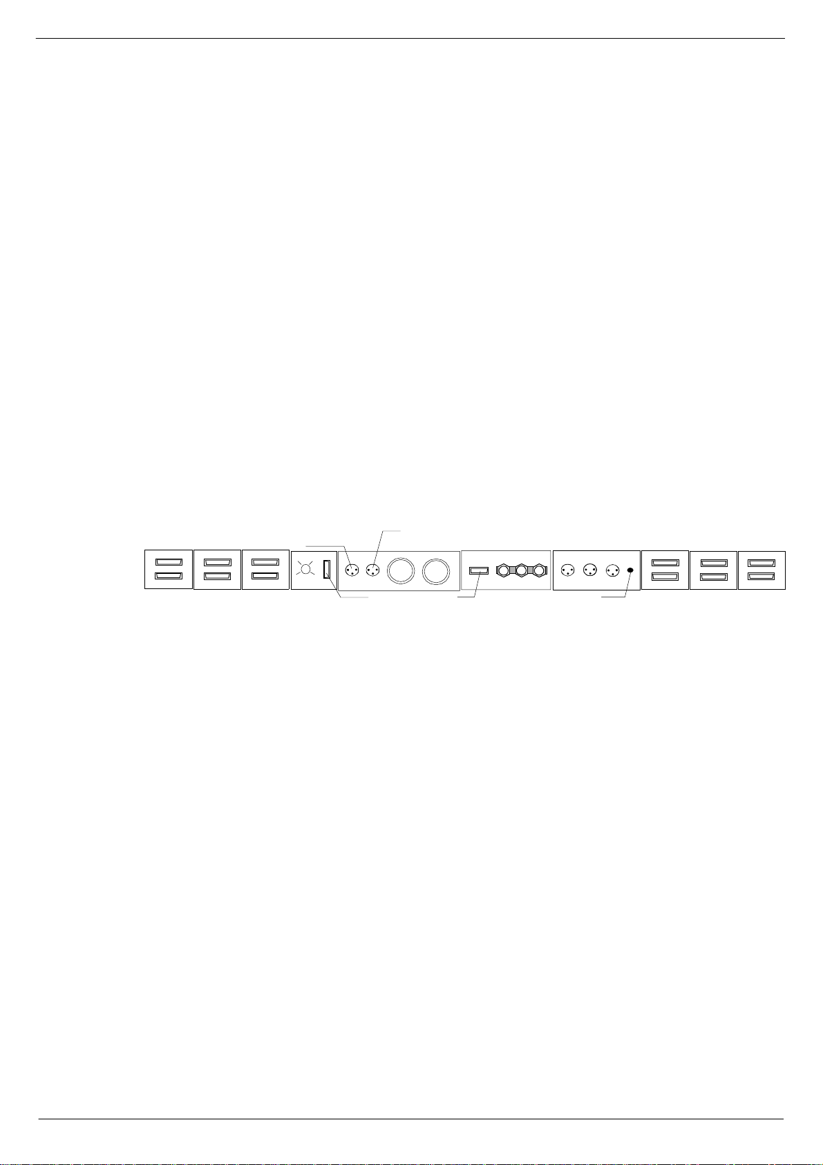
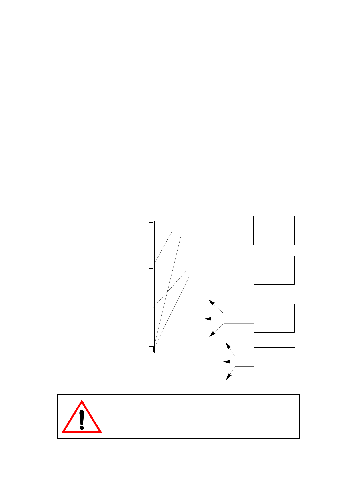
415 )UDPH#UHDU#FRQQH FWLR QV
HEADPHONES NEXT FRAME
4
5
AUDIO BUS
FIG 1-1. F-Type frame rear connections.
6
7
DATA BUS
FRAME TO FRAME
FRAME
SELECTOR
The connections on the F-Type console rear frame include the following (from left to
right):
■■■■
■■■■
■■■■
■■■■
■■■■
■■■■
■■■■
■■■■
■■■■
■■■■
■■■■
■■■■
■■■■
■■■■
■■■■
INPUT TO H EADPHO NES JACK SOC K ETS
COMMS TO CCM
PSU 1
PSU 2
PSU INDICATOR
FROM PFL NEXT LIGHTS
GND - 0 - FRAME
5 AMP FA N FUS E
Audio Bus - fr ame to frame, up to 4 frames c an be connected.
Data Bus - frame to frame
Frame selector
Comms to CCM
PFL output to next frame.
PFL input from module.
PSU1 co nnector
PSU2 co nnector
Output for monitoring of PSUs
GND - 0 - FRAME
Littlite input from PFL module.
Littlite output to next frame.
Littlite output to lights
Audio Bus
Data Bus
4
5
AUDIO BUS
FRAME TO FRAME
6
7
DATA BUS
The use of these connectors is described in 1.3.5 Main and extension frame power
connections, 1.4 Connecting the console frames and 1.5 Connect Console Automation System.
Revision F2005-2 F-Type
Page 10
1-2 Connecting the mixer systems
416 &RQQHFW#3RZHU#VXSSO\#V\VWHP V
41614 3RZHU#VXSSO\#V\VWHP#GHVFULSWLRQ
Cadac consoles are designed to allow the use of two independent power supply systems in a redundant configuration – “main” and “ backup”. Both sets of power supply
units are used to power the console system so that under normal conditions, the
‘loa d’ is sh ar ed b etw e en th e “ m ai n” a nd “ bac ku p” PS U’s. If a f a ul t oc c urs i n on e o f th e
power units (causing it to ‘shut-down’), the remaining power unit will power the console.
For smaller B-Type consoles (consuming no more than 44A), it is possible to use the
8400 PSU. See 1. 3. 7 8 400 switch-mode power supp ly uni t.
One ±18V PSU and one +13V/+48V PSU is referred to as a “PSU System”.
Designate one pair of power supply units as “SYSTEM 1" and the other as “SYSTEM
2". PSU System 1 .and PSU System 2 should be connected to the same
on the same ‘spur’, wherever possible. In situations where it is necessary to provide
a separate ‘feed’ to each PSU system pair, make sure that the cable lengths are the
same. This is to minimize any induced a.c. power input noise by ensuring that the
“EARTH IMPEDANCE” is the same for both PSU systems.
phase
and
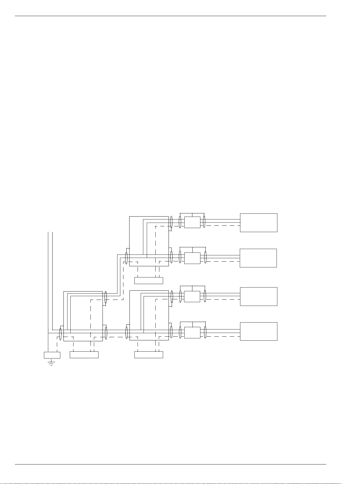
$5($#%5$1&+#3$1(/
1#/
$5($#%5$1&+#3$1(/
*1'#%$5 *1'#%$5
0$,1#*5281'#5()(5(1 &(#($57+#(/(&752'(#6<67(0
$5($#%5$1&+#3$1(/
/
368#4$
-
-
-
-
1
(
/
1
(
/
1
(
/
1
(
368#4%
368#5$
368#5%
FIG 1-2. AC mains grounding diagram (single phase 200-240V)
F-Type Revision F2005-2
Page 11

Connecting the mixer systems 1-3
The a.c.-input connectors on each power supply unit have three conductors: ‘LIVE’
(brown), ‘NEUTRAL’ (blue) and ‘EARTH’ (yellow/green). For safety and electromagnetic compatibility cons iderations, it is essential that the ‘EARTH’ conductor is connected on all PSUs
continuous c i rcuit to the “ze ro-signal reference potential” point in the building. The
ZSRP point in a building is usually found near the place where the a.c. ‘mains’ supply
enters the building (often referred to as the “MAIN GROUND REFERENCE EARTH
ELECTRODE SYSTEM”). The basic concept for correct a.c. mains wiring distribution
is shown in figure 1-1. If you need further information about this complex subject,
please refer to “Grounding Systems and their Implementation” by Charles Atkinson
and Philip Giddins published in the AES Journal Vol. 43, No. 6 – June 1995.
The grounding scheme in CADAC consoles is designed to meet the rigorous EEC
Elec tromagne tic Compatibility
induced in the console frame(s) is directed to the “local” ZSRP, which is the metalwork of the power supply units. In order to take full advantage of the “RF noise immunity” capability of the CADAC system, P SU a.c. mains cables and the a.c. mains
supply EARTH conductor mus t be connected correctl y.
the a.c. supply has an ‘EARTH’ conductor that has a
and
requirements (EMC Directive - 1996). Any RF noise
41615 $&#SRZHU#UHTXLUHPHQWV
CADAC power supply units are designed to run from a minimum of 208 V up to a
maximum of 260V, 50/60Hz a.c. In many parts of the world the normal a.c. singlephase supply is 100-127V, this means that the CADAC power supply units must be
connected across two of the phases in the three-phase a.c. supply, see 1.3.4 Connecting to a 3-phase outlet.
41616 6ZLWFK00RGH#3RZHU#6XSSO\#8QLWV
CADAC 8019 and 8020 switch- m ode power supply units are designed to run from a
minimum of 208V up to a maximum of 260V a.c, 50/60Hz.
The 80 19 “18 V ” uni t is r a te d at 10 0A per r a il an d the 8 020 “1 3V” un it is rat ed at 100A.
See also Appendices, B. Switch-Mode Power Supply Units,
;34<#´4;9µ#VZLWFK0PRGH#SRZHU#VXSSO\#XQLW
The ol der version of 8019 ±18v unit is based on two AD VANCE F20006 ‘powerblocks’, with additional circuitry as shown on CADAC drawing number C3.801 5. The
new versio n is based on PowerOne PSUs (serial number 34949 onwar ds).
The a .c. inpu t is connected to the PSU via a 3-core cable, CMA reference 3183TQ –
BASEC approved, rated at 20A.
FIG 1-3. 8019 power supply unit
Revision F2005-2 F-Type
Page 12
1-4 Connecting the mixer systems
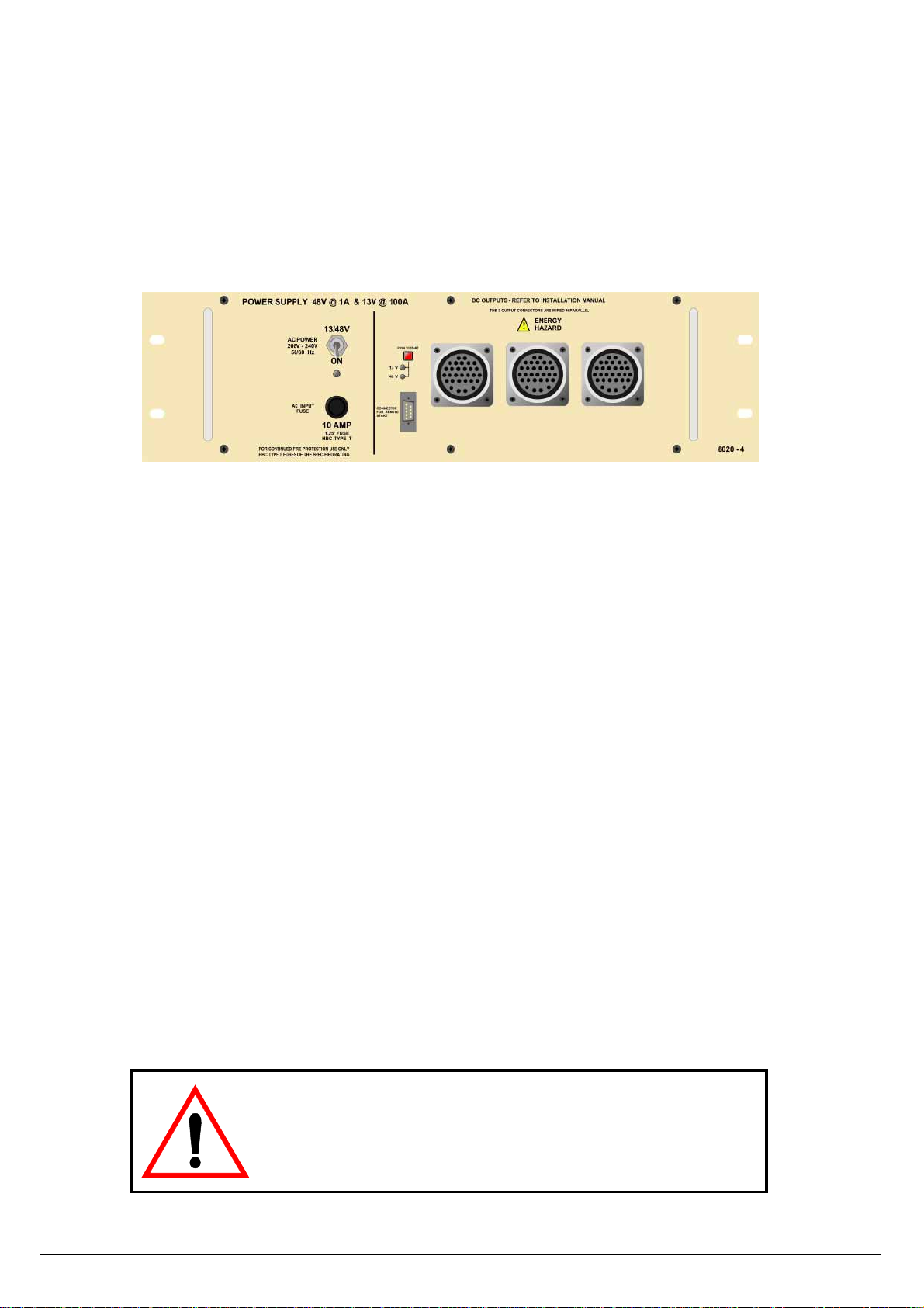
;353#´469µ#VZLWFK0PRGH#SRZHU#VXSSO\#XQLW
The ol der version of 8020 +13v/48v un it is based on one ADVANCE F20006 ‘p owerblock’, with additional circuitry as shown on CADAC drawing number C3.8016. The
new version is based on PowerOne PSUs (serial number 34949 onwards).
The a .c. inpu t is connected to the PSU via a 3-core cable, CMA reference 3183TQ –
BASEC approved, rated at 20A.
FIG 1-4. 8020 power supply unit
5HSODFLQJ#D#SRZHU#VXSSO\#XQLW
If replacing a switch-mode power supply unit is required, please note the following:
Make sure that the pow er supply s ystem’ s power switches are in the position
■■■■
OFF and disconnected from the mains.
The work should only be carried out by a s uitably qualified electrician.
■■■■
Be careful to observe correct polari ty when connecting the new PSU.
■■■■
Note that a console must never have one voltage without the ot her, for example
■■■■
+18V must never be fed into the console without -18V.
When switching the power supply system back ON after replacement has taken
place, make sure that both LEDs on the front of the PSU-system come on. If only
one LED comes on, let go of the ON push-button immediately. Failure to do so may
lead to fire hazar d and major damage to the console.
NO TE:
Under no circumstances, should the 8019 or 8020
PSU be used without a SAFETY EARTH connection. Failure
to follow this instruction is both a fire and safety hazard.
F-Type Revision F2005-2
Page 13
Connecting the mixer systems 1-5
41617 &RQQHFWLQJ#WR#D#60SKDVH#RXWOHW
Connection to a 3-phase outlet is r equired on sites where the system vol tage
between any one of the phases and neutral is 100-127V and the voltage between
any two of the phases is 200-240V. Before connecting to any 3-phase outlet, please
refer to a qualified electrician who under stands your partic ular installation and the
local safety and wiring regulations. Under no circumstances should the 8019 and
8020 switch-mode power supply units be operated without the green/yellow safety
earth conductor connected to the building safety earth conductor system. Each
power unit is equipped with an input supply filter whose reference ground conductor
is the chassis. Failure to connect the green/yellow safety earth conductor to the correct eart h/ground building reference is a safety and fire hazard.
1. Connect the LIVE (Brown) conductor on the “system 1” 8019 unit to the phase 1
(L1, RED) terminal on the 3-phase power outlet connector.
2. Connect the NEUTRAL (Blue) conductor on the “system 1” 8019 unit and the
LIVE (Brown) conductor on the “system 1” 8020 unit to the Phase 2 (L2, YELLOW) terminal on the 3-phase power outlet connector.
3. Connect the NEUTRAL (Blue) conductor on the “system 1” 8020 unit to the
Phase 3 (L3, BLUE) terminal on the 3-phase powe r outlet connector.
4. Connect the EARTH (Yel low/Green) conductor on the “system 1” 80 19 unit and
the EAR T H ( Yello w/ Gr een ) co nd uc to r on the “sys te m1 “ 8 020 un it to th e SA FET Y
EAR TH (Yellow/Green) t erminal on the 3-phase power outlet connector .
5. Repeat 1-4 for the “system 2” power units.
3+$6(#4#+/4/#5(',
3+$6(#5#+/5/#<(//2:,
3+$6(#6#+/6/#%/8(,
6$)(7<#($57+
<(//2:2*5( (1
/5
6$)(7<#($57+
/4
/5
/4
/LYH
1HXWUDO
(DUWK
/LYH
1HXWUDO
(DUWK
/LYH
1HXWUDO
(DUWK
/LYH
1HXW UDO
(DUWK
;34<
;353
;34<
;353
FIG 1-5. Connecting to a 3-phase outlet
(100-127V/200-240 system voltages)
NOTE:
Connection between two phases in a 3-phase outlet should under no
6$)(7<#($57+
circumstances be carried out where the single-phase voltage (the voltage
between one of the phases and neutral) exceeds 127V. The installation
should be carried out by a qualified electrician who understands your particular installation and the local safety and wiring regulations.
Revision F2005-2 F-Type
Page 14
1-6 Connecting the mixer systems
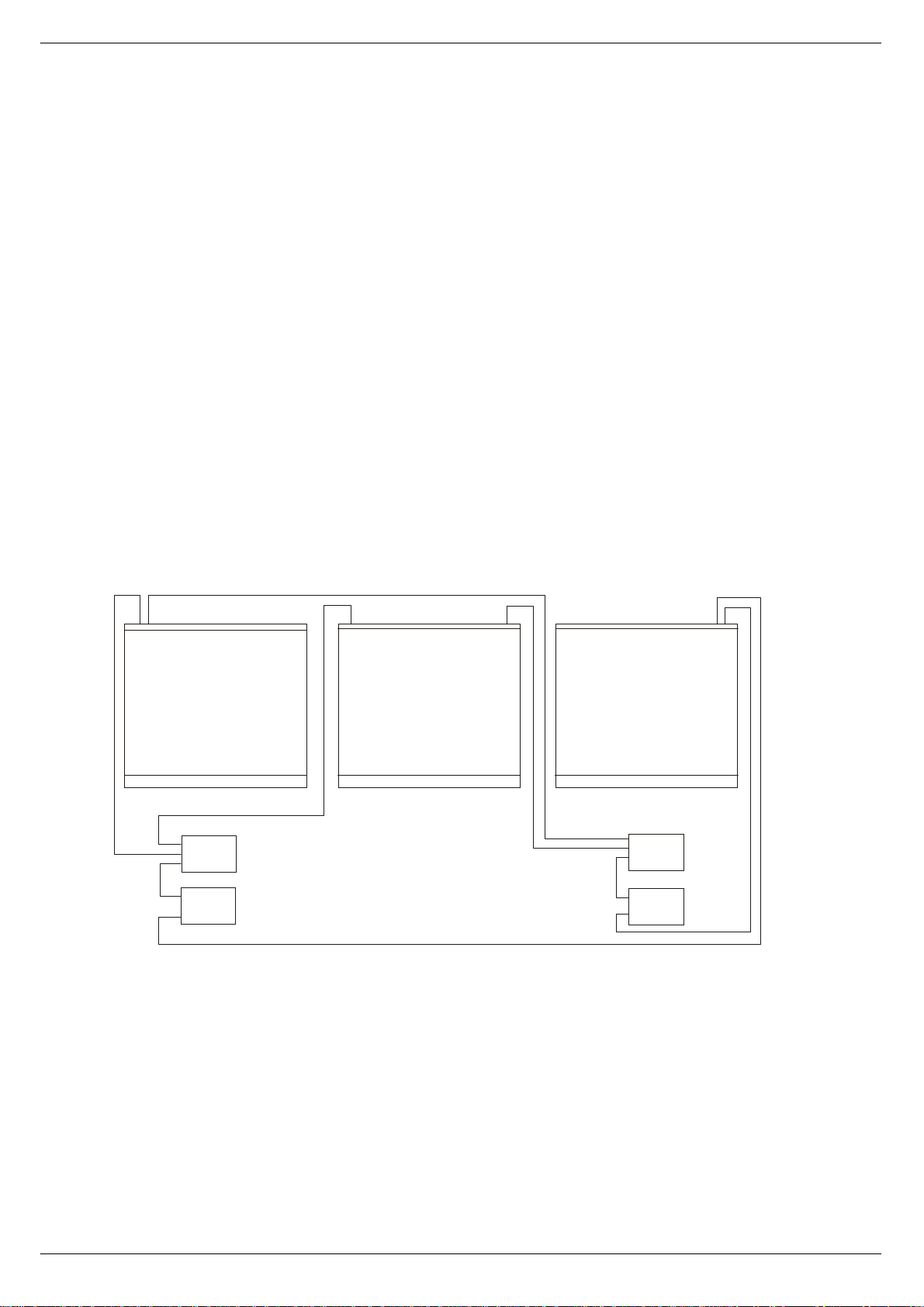
41618 0DLQ#DQG#H[WHQVLRQ#IUDPH#SRZHU#FRQQHFWLRQV
See fig 1-4 below for schematics of the frames power connections.
1. Using a short U-LINK cable (supplied), co nnect one of the outputs on the ±18V
PSU to one of the outputs on the +13V/+48V PSU in the “SYSTEM 1" power
supply rack. This operation “links” the d/c outputs on both power supply units in
the rack so that ±18V, +13V and +48V is available on all remaining output connectors on either power unit.
2. Co nn ec t t he seco nd s ho rt “U -LI NK” c abl e ( s up plie d) b etw e en the ± 18 V PS U an d
the +13V/+48V PSU’s in the “SYSTEM 2" power supply rack.
3. Connect a PSU cable between the “SYSTEM 1" rack and the “PSU SYSTEM 1"
connector on the MAIN FRAME.
4. Connect a PSU cable between the “SYSTEM 2" rack and the “PSU SYSTEM 2"
connector on the MAIN FRAME.
5. Connect a PSU cable between the “SYSTEM 1" rack and the “PSU SYSTEM 1"
connector on the EXTENSION FRAME 1.
6. Connect a PSU cable between the “SYSTEM 2" rack and the “PSU SYSTEM 2"
connector on the EXTENSION FRAME 1.
7. Repeat procedures 5. and 6. for EXTENSION FRAME 2 (a 3 fram e console).
368#6<67 (0#4#+“4;9,
368#6<67(0#4#+7;92.469,
368#6<67(0#5#+“4;9,
368#6<67(0#5#+7;92.469,
FIG 1-6. Power connections
F-Type Revision F2005-2
Page 15
Connecting the mixer systems 1-7
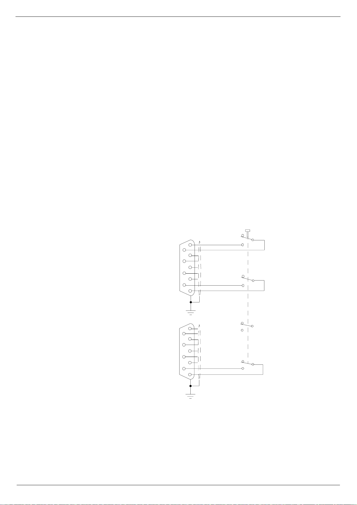
41619 ;34<#DQG#;353#FRPELQHG#5HPRWH#VWDUW
Each 801 9 and 8 02 0 s w it ch- mod e p o we r supp ly is fi t ted wi th a f ron t p an el mo un ted 9
way ‘D-type’ connector. This connecto r is labelled “Connections for Remote Start”.
You may connect a single remote start switch to each unit, have one switch start a
“system” pair, or wire up a sing le switch to start “system 1” and “system 2” all at the
same time.
Fig 1-5 applies to 8019 and 8020 PSUs up to serial number 34949 and shows the
circuit for starting up a “system” pair with a single switch. This has pr oved to be the
most popular method of connecting the remote start facility. This circuit can easily be
extended to provide a single switch remote for all four PSUs i f required.
For 8019 and 8020 PSUs from serial number 34950 onwards, see fig 1-6 and 1-7.
NOTE:
The remote must be a ‘momentary’ type. You will need a two-pole switch for a
■■■■
single PSU, a four-pole switch for a “syste m” pair, or a six-pole switch fo r controlling
all four units.
The remote switch(es) must be mounted on a metal panel.
■■■■
Use shielded cable fo r the remote switch w iring.
■■■■
The 9-way ‘D-type’ free plug must have a conductive shell. This is to ensure that
■■■■
the cable shield connects directly to the PSU unit chassis.
Connect the cable shield to the metal panel where the remote start switch(es)
■■■■
are mounted.
TO CONNECTION
FOR REMOTE START
ON 8019 FRONT PANEL
TO CO NN E C TIO N
FOR REMOTE START
ON 8020 FRONT PANEL
CUP/TAG SIDE
5
9
4
8
3
7
2
6
1
5
9
4
8
3
7
2
6
1
PANEL MOUNTED 4-POLEVIEW FROM SOLDER
MOMENTARY SWITCH
NOTE: CABLE SCREEN IS
CONNECTED AT BOTH ENDS
FIG 1-7. Remote start of 8019/8020 up to serial number 34950
Great care must be taken with the wiring of the switch(es) to ensure that no short-circuits can occur between a ny two power supply units.
Revision F2005-2 F-Type
Page 16
1-8 Connecting the mixer systems
VIEW FROM SOLDER
CUP/TAG SIDE
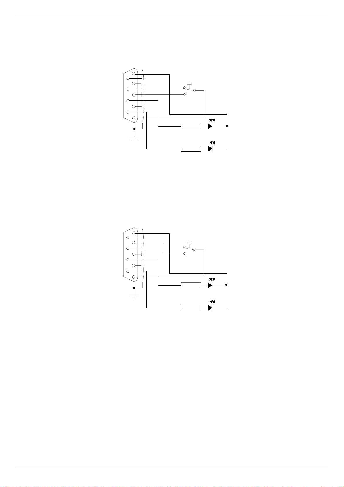
FIG 1-8. Remote start of 8019 PSU
(from se rial number 34950)
5
9
4
8
3
7
2
6
1
VIEW FROM SOLDER
CUP/TAG SIDE
5
9
4
8
3
7
2
6
1
“START” MOMENTARY PUSH BUTTON
18V
300R
OVER
TEMPERATURE
300R
POWE R F AILURE
“START” MOMENTARY PUSH BUTTON
13V
FIG 1-9. Remote start of 8020 PSU
(from se rial number 34950)
300R
OVER
TEMPERATURE
300R
POWER FAILURE
F-Type Revision F2005-2
Page 17

Connecting the mixer systems 1-9
4161: ;733#VZLWFK0PRGH#SRZHU#VXSSO\#XQLW
FIG 1-10. 8400 po wer supply unit.
CADAC 840 0 switch- mode power supply units are designed to run from a minimum
of 208V up to a maximu m of 260V a.c, 50/60Hz.
The 84 00 is rated thus +13V@92A, ±18V @44A and 48V@5A.
The a .c. inpu t is connected to the PSU via a 3-core cable, CMA reference 3183TQ –
BASEC approved, rated at 20A.
The 8400 unit is based on one POWER ONE RPMS-ETETGDGD1ETK Pow er block,
with additional circuitry as shown on CADAC drawing numbe r C3.8397.
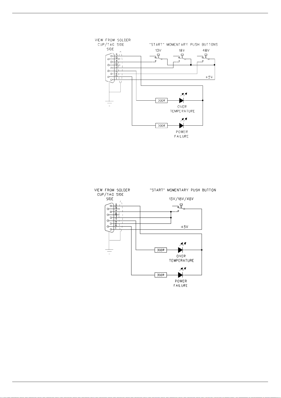
4161; 5HPRWH#VWDUW#RI#;733#368
Each 8400 switch-mode power supply pro v ides the following outputs: 13v, ±18v and
48v. Each PSU i s fitted with a front panel mounted 9-way 'D-t ype’ connector labelled
‘Connections for Remo te Start’. If a remote start facil ity is used, Power Failure and
Over-Temperature LEDs may also be fitted with the remote start switches if required.
Fig 3-15 shows the circuit for starting up a “system” with a single switch. This has
proved to be the most popular method of connecting the remote start facility. This circuit can easily be extended to provide a single switch remote for all four PSUs if
required. If muliple switches are to be used, see fig 3-14.
NOTE:
The remote start switch must be a ‘momentary’ type. You can use 3 separate sin-
■■■■
gle pole swit ches for each Power Supply to turn on 13v,±18v and 48v outputs of the
PSU alternatively use one single pole for the whole lot.
The remote switch(es) must be mounted on a metal panel.
■■■■
Use shielded cable fo r the remote switch w iring.
■■■■
The 9-way ‘D-type’ free plug must have a conductive shell. This is to ensure that
■■■■
the cable shield connects directly to the PSU unit chassis.
Connect the cable shield to the metal panel where the remote switch(es) are
■■■■
mounted.
Revision F2005-2 F-Type
Page 18
1-10 Connecting the mixer systems
FIG 1- 11. R emote s tart o f
PSU 8400 with multi ple
switches.
FIG 1-12. Remote start of PSU
8400 with a single switch
Great care mus t be take n when wiring the switch(es) to ensure that no short-circuits
can occur between any two power supply units.
F-Type Revision F2005-2
Page 19

Connecting the mixer systems 1-11
417 &RQQHFWLQ J#WKH#FRQVROH#IUDPHV
41714 $XGLR#%XV#2#'DWD#%XV#&RQQHFWLRQV
If the console i s used in a mul ti-fram e configuration then the busses need to be connected in a ‘daisy chain’ fashion.
four audio and two data busses plus fader bus (see fig 1-13). The bus cables are
simply linked between similar co nnectors on the end of the nearest frame.
Make sure that each frame has its “Frame Select” switch set to a different number.
Each end
of a frame has seven bu s connectors -
FIG 1-13. Audio/Data Bus connections.
See also appendix A. Important information re garding EMC .
41715 )DGHU#FRPPXQLFDWLRQV
When motor faders are used in ext ension frames, a 9-way “FADER COMMS” cable
must be connec ted between the CCM connectors shown (see fig 2-3) and the
COMMS input on the extension fr ame rear panel.
Extension frames fitted with motor-fader s require control da ta from the CCM. Three
9-pin female connec to rs lo ca te d o n the r e ar pa ne l of t he CCM ar e co nn ecte d dir ec tly
to the extension frame us ing the supplied ‘fader comms’ cable. The frame containing
the CCM sends motor data fader data, via the 7303 interface module (always
mounted directly below the CCM on J-type consoles).
4
5
AUDIO BUS
FRAME TO FRAME
6
7
DATA BUS
COMMS TO CCM
FRAME
SELECTOR
Thus , a 3 frame console would requi re two “FADER COMMS” cables:
“FADER COMMS on EXTENSION FRAME 1 TO “FADER COMMS 2” on CCM
“FADER COMMS on EXTENSION FRAME 2 TO “FADER COMMS 3” on CCM
41716 3)/
PFL mixing amplifiers are located in the “O scillat or/Commu nications ” module. There
are two PFL outputs:
PFL Direct is a line lev el output that appear s on an XLR 3-32 connector on the
■■■■
rear panel of the OSC/Comms module, labelled “ PFL DIRECT”;
PFL to H eadphones is a high level output suitab le for driving headphones that
■■■■
appears on an XLR 3-32 connector
panel of the OSC/Comms module,labelled “PFL TO HP”.
Revision F2005-2 F-Type
a TRS jack socket connector on the rear
and
Page 20

1-12 Connecting the mixer systems
The PFL to Head ph on es sig na l c an be co on ne ct ed to th e T RS jack sockets mo unte d
on the front of the console frame by using the “OSC/COMM TO FRAM E” cable supplied. This cable has a male XLR 3-pin connector on one end and a female XLR 3pin on the other end. Connect one end of the “Osc illator/Communications” module’s
“PFL TO HP” connector and the other end to the rear frame connector labelled
“FROM PFL HEADPHONE XLR”.
Additional in ter-frame connections are required to enable the PFL signals from modules i n extension (side) frames to be monit ored. Use the cable(s) labelled “PFL
FRAME TO FRAME” to interconnect two or more frames:
Connect one end of a “PFL FRAME TO FRAME” cable to the connector labelled
■■■■
“TO NEXT FRAME” on the console frame containing the “Osc/Communications”
module.
Connect the other end of a “PFL FRAME TO FRAME” cable to the connector
■■■■
label led “FR O M PFL HEADPHONE XLR” on the next f rame.
Repeat this procedure for all other frames in the c onsole system.
41717 /LWWOLWHV
Surface illumination of the console is provided by the use of two or more “Littlite”
units that plug into the top bar of the console frame. Control for the “Littlites” - on/off
and in tensity - is located on the “Oscillator/Communi c ations” module. The variable
voltage power supply is mounted inside the console f rame.
Two cables are required to interconnect the “Littlit e” controls, the variable volt age
power supply and the lamp units.
Connect one of the cable labelled “OSC TO LITTLITES” to the connector on the
■■■■
rear panel of the “Oscillator/Communications” module labelled “LITTLITES” (this
cable has 4-pin XLR male and female connectors).
Connect the other end of the cable labelled “OSC TO LITTLITE” to the connector
■■■■
on the rear panel of the conso le frame labelled “FROM PFL MODULE”.
Connect one end of the cable labe lled “LITTLITE FRAME TO BAR” to the con-
■■■■
nector on the rear panel of the console frame labelled “TO LIGHTS” (this cable has a
4-pin male XLR connector at one end and a 5-pin XLR connector at the other end).
Connect the other end of the cable labelled “LITTLITE FRAME TO BAR” to the
■■■■
5-pin XLR-connector mounted at the rear of the top bar on the console frame.
Additional in ter-frame connections are required to enable the LITTLITE control signals to be delivered to any extension frame(s) in the console system. Use the
cable(s) labelled “LITTLITE FRAME TO FRAME” to interconnect two or more frames.
Connect one end of a “LITTLITE FRAME TO FRAME” cable to the connector
■■■■
labelled “TO NEXT FRAME” on the console frame containing the “Oscillator/Communications” module;
Connect the other end of a “LITTLITE FRAME TO FRAME” cable to the connec-
■■■■
tor labelled “FROM PFL MODULE” on the next frame;
Connect one end of a cable labelled “LITTLI TE FRAME TO BAR” to the connec-
■■■■
tor on the rear panel of the console frame labelled “TO LIGHTS” (this cable has a 4pin male XLR connector at one end and a 5-pin XLR co nnector at the other end.
Connect the other end of a cable labelled “LITTLITE FRAME TO BAR” to the 5-
■■■■
pin XLR connector mounted at the rear of the top bar on the console frame.
Repeat this procedure for all other frames in the c onsole system.
41718 368#,QGLFDWRU
Two sets of four LEDs are in corporatedinto the CCM front panel to give the operator
visual indication that the “main” (PSU System 1) and “backup” (PSU System 2)
power supply units are working correctly. A cable,labelled “PSU IND.” is supplied to
interconnect the CCM and the console frame.
F-Type Revision F2005-2
Page 21
Connecting the mixer systems 1-13
Connect one end of the “PSU IND” cable to the “PSU IND” 15-way male D-sub
■■■■
connector on the CCM.
Connect the other end of the “PSU IND” cable to the “PSU IND” 15-way female
■■■■
D-sub connector on the rear console frame adjacent to the two multi-pin power input
connectors.
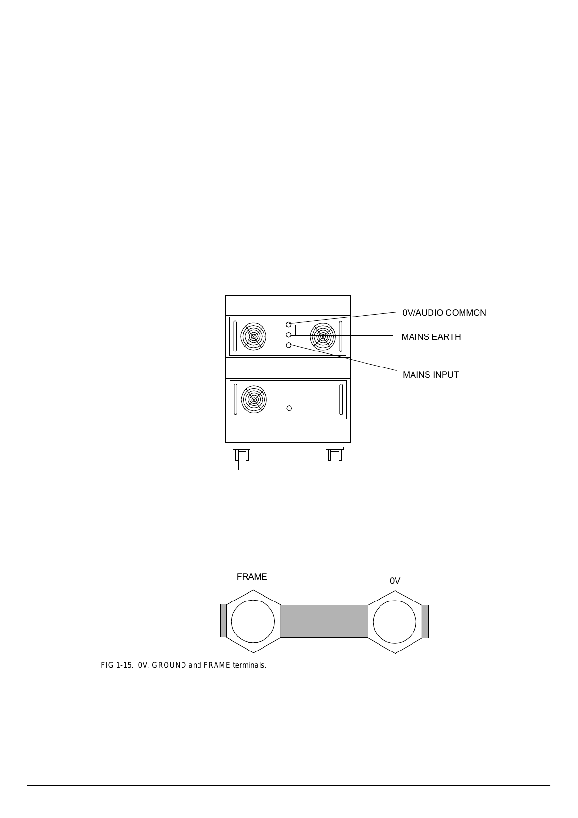
41719 (DUWK/#39#DQG#)UDPH#&RQQHFWLRQV
Figure 1-6 shows the rear panels of the power supply units in a single PSU system.
Under normal conditions, the 0V and Mains-Earth terminals can be connected on
both PSU systems. However, if the a.c. input lines to each pair of PSU’s has a different length, you may find that the 0V and Mains-Earth terminals can only be linked on
set of power supplies, f or minimum system noise .
one
FIG 1-14. PSU system.
The 0V or FRAME terminals on a PSU need
or FRAM E connections on console frames. The shielde d power supply cables are
connected to the frame at both en ds.
be dir ec tly co nn ec te d t o th e 0 V and/
not
392$8',2#&20021
0$,16#($57+
0$,16#,1387
In addition to the terminals on the back of the PSUs, there are
nections on the rear of ea ch console frame. The shorting-bar link between the 0V
and “FRAME” terminals on each frame
large diameter ‘frame-link’ cables (supplied with multi-frame consoles), must be connected. Always make sure that ‘frame-link’ cable nuts are tightened against the copper bar.
be conn ected. For minimum noise, the
must
0V
and
FRAME
con-
)5$0(
FIG 1-15. 0V, GROUND and FRAME terminals.
The 0V and FRAME t e rminals are linked in the factory with a copper bar. This bar
should never be removed when the console is in normal use. Note that
cannot be delivered from the input modules to the 48V bus if the copper bar is
Power
missin g, beca us e t he scre en ed mic rop ho ne input ca b l es w il l not be te rmina te d. I t wil l
also cause damage to the motor faders.
Revision F2005-2 F-Type
39
Phantom
Page 22

1-14 Connecting the mixer systems
418 &RQQHFW#&RQVROH#$XWR PD WL RQ#6\VWHP
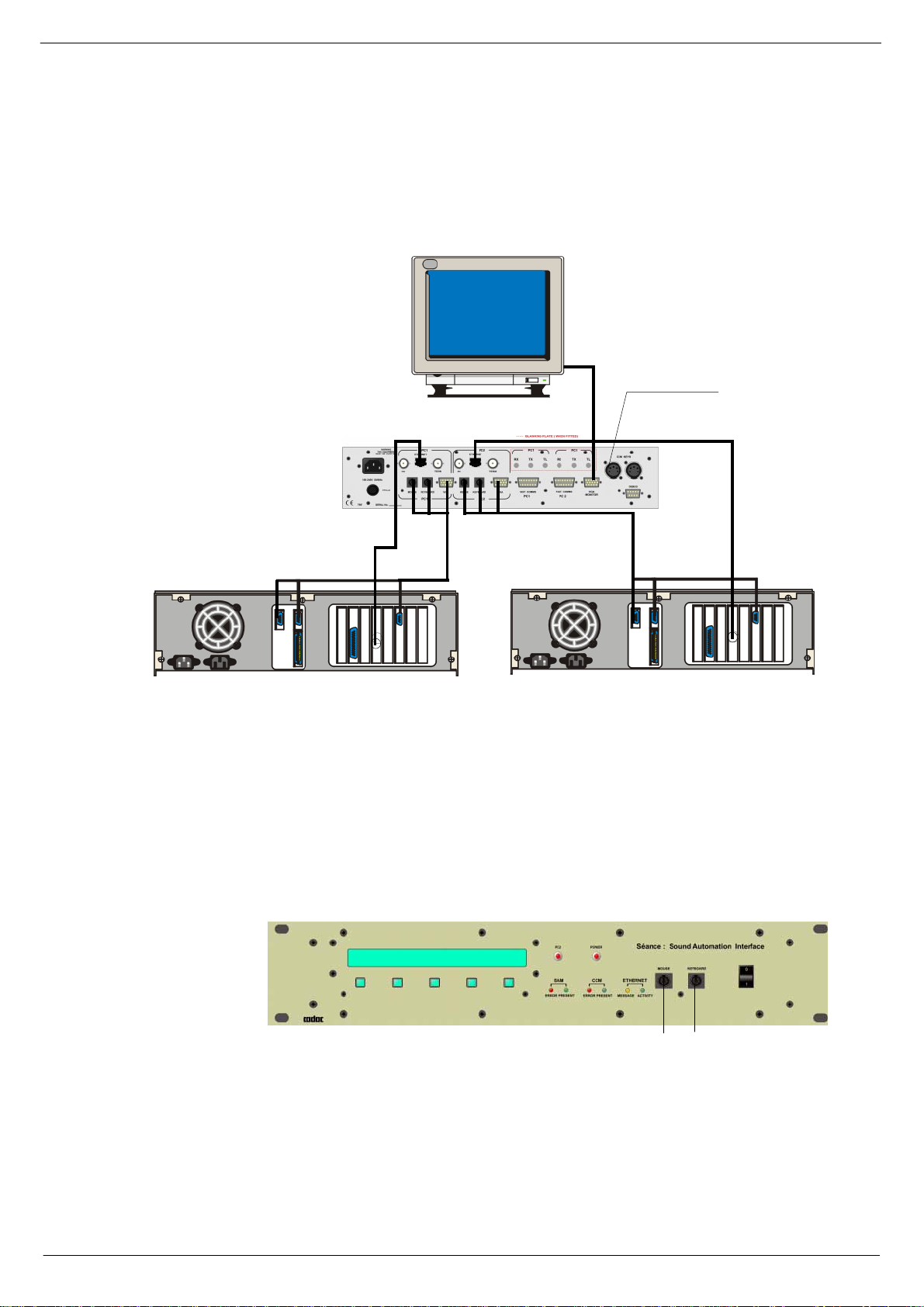
41814 &RQQHFWLRQV#0#%1&
Figu res 1 - 9 be lo w a nd 1- 1 1 s how h o w t o c onn ec t th e S éan ce box to the cons ole an d
the co mputers running SAM., BNC type c onnection.
7R#UHPRWH#3.1
83#RKP#WHUPLQDWLRQ
(WKHUQHW#WHUPLQDWHG#DW#3&#HQG
0RXVH
.H\ERDUG
9*$
(WKHUQHW#WHUPLQDWHG#DW#3&#HQG
0RXVH
.H\ERDUG
9*$
3&4#ZLWK#(WKHUQHW#FDUG 3&5#ZLWK#(WKHUQHW#FDUG
FIG 1-16. Séance rear panel connections for BNC
41815 (WKHUQHW#0#%1&
The Séance box communicates with the PCs over a 10Base-2 Ethernet connection
via a 50 ohm BNC cable terminated at each end with a 50 ohm terminator. The
Séance box has two B NC connectors for each PC interface, which are wired in parallel in side. A 50 ohm terminat or plugs into the BNC socket la belled TERMINATOR
and th e Ethernet ca ble plug s into the BNC socket labelled COMPUTER. A terminator and T-piece are used to connect the Ethernet cable to the PC.
0LQLPXP#VSHFLILFDWLRQ#IRU#D#3&#XVHG#ZLWK#WKH#############
6RXQG#$XWRPDWLRQ#0DQDJHU#6RIWZDUH
To run the Sound Automation Manager software requires a PC with at least the
performance and peripher als as listed below:
PC Pentium 133 or later or compatible computer
Windows ®’98 (second edition), 2000, XP or XP Pro
Graph ics card 1024 x 768 pix els, 16 bit colour or better
Ethernet interface 10Mbit/sec with 10base2 c onnector (BNC)
128MB RA M
20 MB free hard disk space
PS/2 keyboard (older 5-pin DIN keyboard can be used with adapter)
PS/2 mouse or pointing device (9-pin’D’-serial devices cannot be used)PS/2
keyboard (older 5-pin DIN keyboar d can be used with adapter)
F-Type Revision F2005-2
Page 23
Connecting the mixer systems 1-15
41816 &RQQHFWLRQV#0#5-78
Figu re 1-10 below and fi g 1-11 show how to connect the Seance box to the console
and the computers running SAM, using RJ45 connection.
7R #UHPRWH#3.1
3&4#ZLWK#(WKHUQHW#FDUG
FIG 1-17. Séance rear panel connections for RJ45
41817 (WKHUQHW#0#5-78
The Seance box can also communicate with the PC via an RJ45 connector depending
on the type of Ethernet-card in the computer. The Séance box has two RJ45 connectors, one for each PC interface. T hese conn ectors should be connected directly into
a comp uter. It is al so po ss ib l e to c onn ec t th e R J45 so ck e ts t o a hub. For det ail s a bo ut
this , contact C ADAC technical support.
0RXVH
.H\ERDUG
9*$
0RXVH
.H\ERDUG
9*$
3&5#ZLWK#(WKHUQHW#FDUG
FIG 1-18. Séance front panel connec tions - BNC and RJ45
0RXVH .H\ERDUG
41818 0RXVH
Each PC has a ‘one-to-one’ PS2 mouse cable, which connects between the PC’s
mouse port and the mouse connec tor on the rear panel of the Séance box. The
mouse plugs into the mouse connector on the front panel of the Séance box.
Revision F2005-2 F-Type
Page 24

1-16 Connecting the mixer systems
41819 .H\ERDUG
Each PC h as a ‘ o ne-o ne ’ PS2 k e yboa r d c ab le , whi ch co nn ects be tw ee n t he PC ’ s k e yboard port and the keyboard connector on the rear panel of the Séance box. The keyboar d connects into the keyboard connector on the front panel of the Séance box.
Converters are supplied to connect to a 5-pin DIN keyboard and 5-pin DIN connectors
on the PC.
4181: 9*$
Each PC has a VGA cable connected between the computer’s VGA output and the
corresponding VGA connector on the rear panel of the Séance box. The VGA monitor
cable plug s int o the VGA con ne c tor.
4181; &&0#NH\V
The Séance interface r eads the PC2 switch on the console’s CCM. The 5-pin XLR
connectors are paralleled together inside the Séan ce. A ‘female-female, one-one cable ’ conn ects to the k eys conne ctor on th e CCM an d the ot her ca n be us ed to c onnec t
to remote PREV and NEXT keys if required.
4181< )DVW#FRSSHU#FRPPXQLFDWLRQV
CADAC’s 15 way “fast copper communications” cables are used to connect between
the Séance box’s fast comms connectors and the CCM. The cable plugged into Fast
comms PC1 on the Séance box must be connected to PC1 on the CCM.
418143 'HEXJ#SRUW
The debug port is standard PC 9-pin serial port that can be used to access the
Séance box’s computer.
418144 0DLQV
The Séance box has a universal power supply and can be connected to AC mains 100
– 240V, 50/60Hz.
418145 )XVH
20mm 315mA fuse
F-Type Revision F2005-2
Page 25
Connecting the mixer systems 1-17
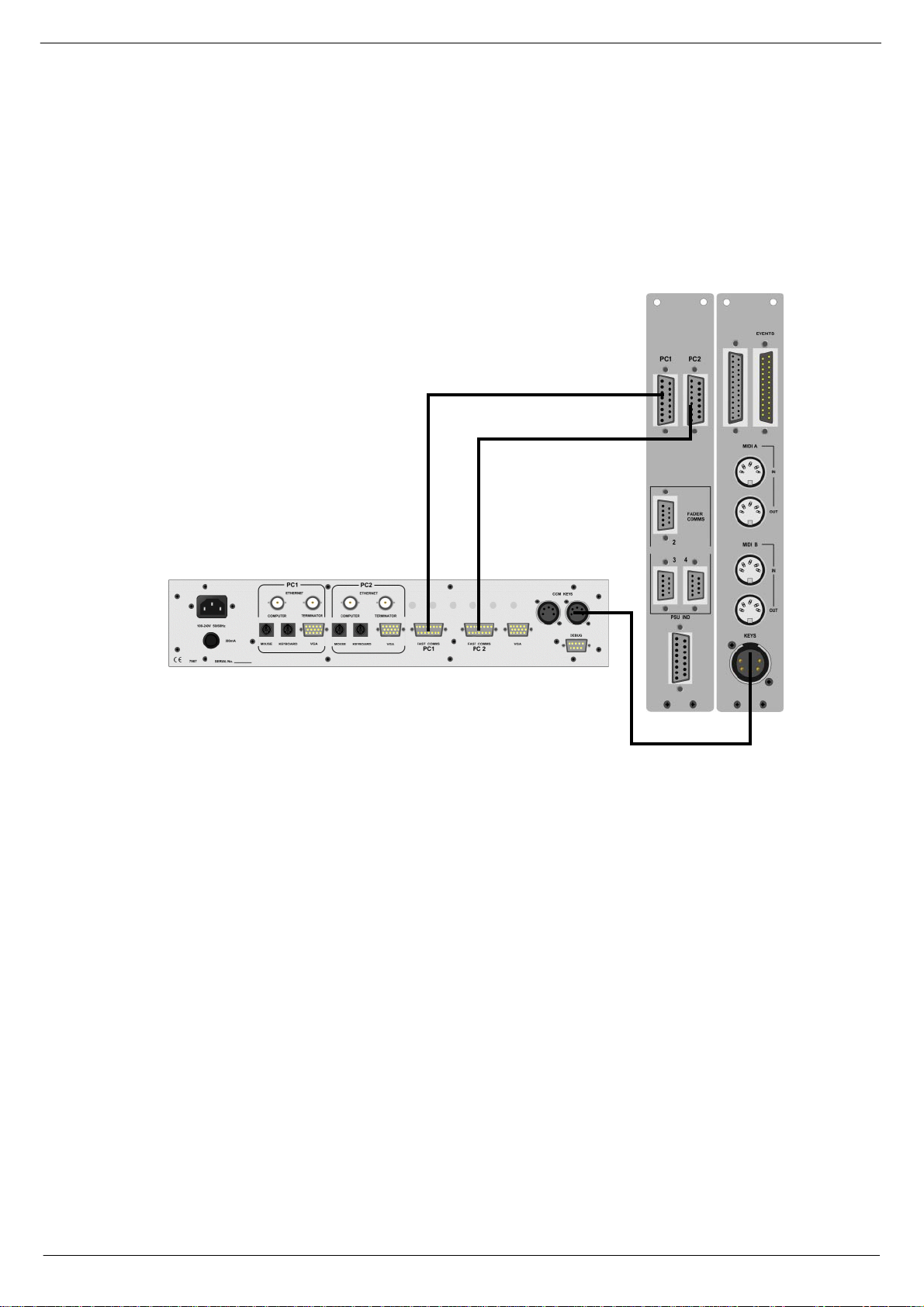
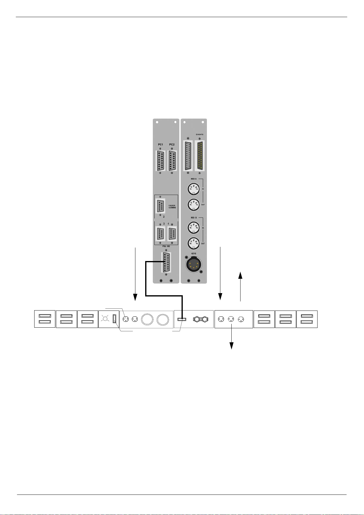
418146 &RQQHFW#6pDQFH#WR#FRQVROH
Figure 1-12 below shows how to connect the Séance Interface to the CCM in the
main co nsole.
FIG 1-19. Connect Séance to CCM.
Using the cables supplied, make the following connections:
1. CCM PC1 to Séance box PC1.
2. CCM PC2 to Séance box PC2.
3. CCM KEYS to Séance box KEYS.
Details on Seance set-up can be found in the Seance Interf ace 7975 User & Installation manu al.
Revision F2005-2 F-Type
Page 26
1-18 Connecting the mixer systems
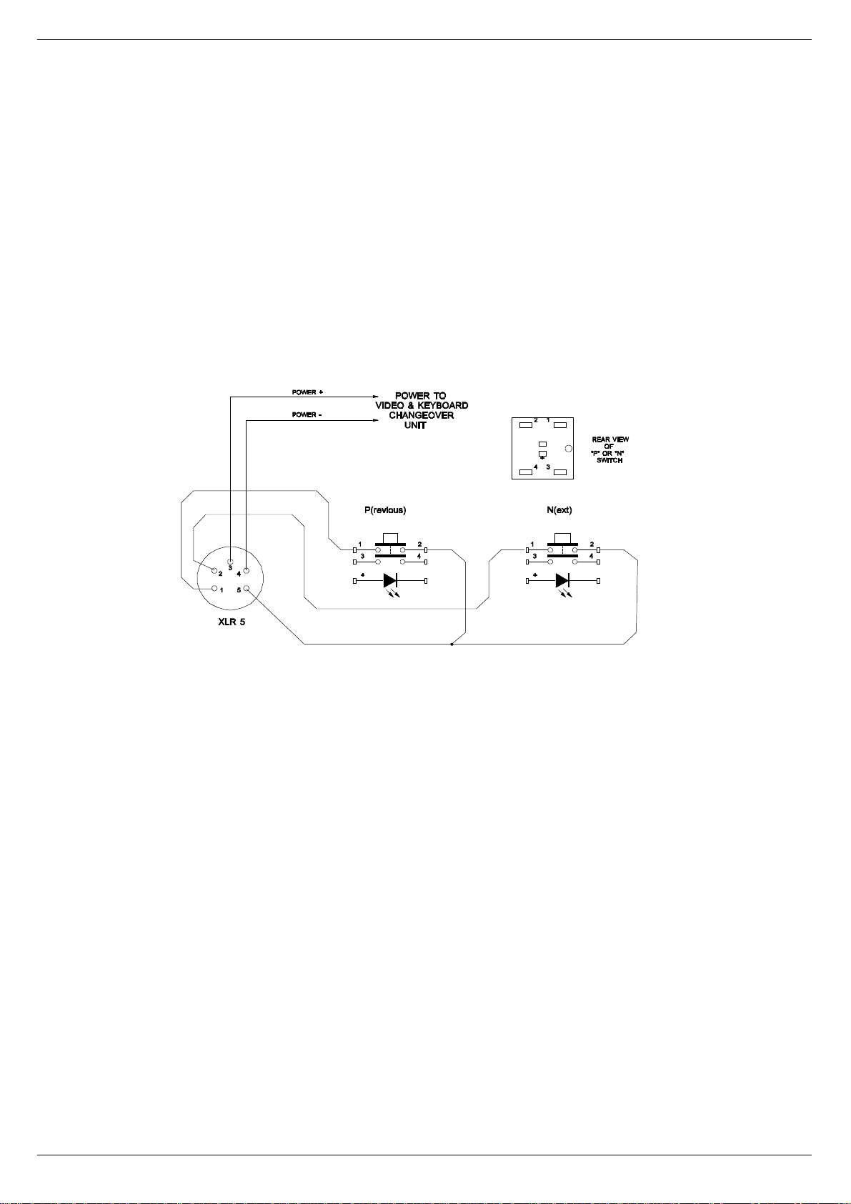
418147 8VLQJ#WKH#9LGHR#DQG#.H\ERDUG#&KDQJH#RYHU#IXQFWLRQ#ZLWK#
6pDQFH#
A single keyboard, mouse and monitor can be used with two computers for main/
back-up vi a th e Séance-box.
The Séance-box is supplied with a cable-kit allowing connections for one keyboard,
one monitor, one mouse and two computers PC1 and PC2.
Using the 5 pin XLR to XLR cable supplied, make the following connection:
CCM KEYS (at the console end) to one of the KEYS-connectors on the rear of
■■■■
the Séance-box.
The second keys connection on Séance is for use with
(see fig 1-20 ).
FIG 1-20. Remote P & N switch wiring detail.
Remote P and N
buttons,
418148 3&5#V\QFKURQLVDWLRQ
Using a Null modem serial interface cable with the appropriate connectors for the
computers in use, make the following connecti on between the two computer s.
PC1 COM 1 or 2 to PC2 COM 1 or 2 (select able in SA M)
■■■■
Two serial port configurations ar e in common use with 9 way or 25 way 'D-Type' connectors.
The two computers will only “trac k” each others’ Cue position if the SAM tracking feature has been enabled, see the SAM manual for details.
F-Type Revision F2005-2
Page 27
Connecting the mixer systems 1-19
419 &RQQHFW#PDLQ#IUDPH#IDFLOLW LH V#IURP#PRGXOHV#WR#
IUDPH
See figure below for instructions on how to connect main frame facilities from modules to frame.
)URP#&2006#PRGXOH#+3)/,
HEADPHONES NEXT FRAME
4
5
AUDIO BUS
6
7
DATA BUS
FRAME TO FRA ME
FRAME
SELECTOR
COMMS TO CCM
FIG 1-21. Connecting the main frame facilities from modules to frame.
PSU 1 PSU 2
PSU INDICATOR
)URP#&2006#PRGXOH
FROM PFL NEXT LIGHTS
FRAME - 0V
7R#QH[W#IUDPH
7R #IUDPH#WRS#EDU
AUDIO BUS
4
5
6
7
FRAME TO FRAM E
Revision F2005-2 F-Type
Page 28

1-20 Connecting the mixer systems
41: 6ZLWFKLQJ#21
41:14 6\VWHP#SRZHU0XS#SURFHGXUH
CADAC consoles are designed to work continuously with two power supply systems
- ‘mai n’ an d ‘b ac k u p’ . The ‘ma in ’ po w er sup ply pai r ( 1 off ‘1 8v ’ un it an d 1 of f 13V/ 48 V
unit ) are designated ‘System 1’. The ‘backup’ power supply pair (1 of f ‘18V’ unit and
1 off 13V/48V unit) are designated ‘System 2’
On each power supply, turn all AC input switches to the ON-position.
Start the ±18 V an d 13V/ 4 8V PSU s (in one PSU syst em) simu lt an eo us ly, by pressi ng
and holding the START-buttons until you hear the relay click. The CCM will cycle
through its self-test routines and any Master Mute sw itches previously selected will
be set ON, thus protecting external equipment from possible DC pulses when the
±18V PSUs ar e sta r ted.
Repeat for PSU system 2. If you cannot start the PSUs simultaneously, start the 13V/
48V first. However, do NOT operate the console for long periods without all power
lines on.
41:15 3RZHULQJ0XS#VHTXHQFH#RI#3&V
Always use the following procedure:
Power up console
■■■■
Powe r up Séance box
■■■■
Select PC1 on the CCM and power up the first computer. Wait until th e PC1
■■■■
computer has completed it s boot-up ro utine, then...
Switch to PC2 on the CCM and p ower-u p the second computer and wait until it
■■■■
has completed its boot-up routine.
Once both comput ers have boote d correctly, they should allow the k eyboard and
monitor to be switched back and forth without problems.
If the overall cable length for the keyboard and monitor are very long (greater than
5m), it may be necessary to use a keyboard and a monitor booster unit to retain keyboard reliability and a clean monitor display.
41:16 6\VWHP#SRZHU0GRZQ#SURFHGXUH
1. On the CCM, press all Master Mute switches to the ON (down) position.
2. Cl os e down the S A M so ftw ar e o n ea ch PC , sh ut do wn Wi nd ow s® a nd sw it c h the
computers off.
3. Switch off the AC mains supply to PSU system 1.
4. Switch off the AC mains supply to PSU system 2.
5. Switch off Séance Box
.
F-Type Revision F2005-2
Page 29

Central Control Module 7896 2-1
5 &HQWUDO#&RQWURO#0RGXOH#:;<9
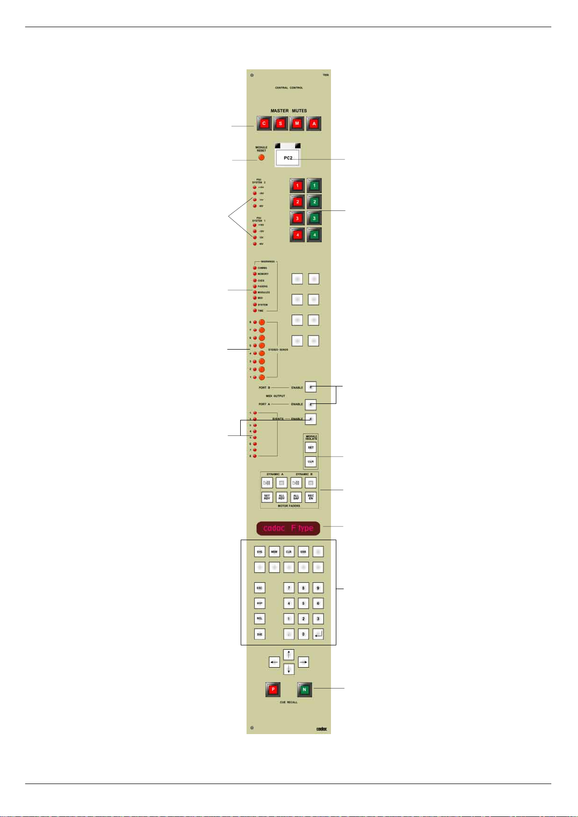
514 &&0#)URQW#3DQHO#VZLWFKHV#DQG#GLVSOD\V
Please re f er t o fi g 2 - 1 o n pag e 2 - 2 f o r the l oc at i on of t he s wi tc he s an d d ispl ays on the
F-Type CCM front panel issue 7896 described on the next page.
D, 0DVWHU#0XWHV
Fo ur separate switches to globally mute the channe ls, subgroups, matrix groups and
aux gr oups. A ll four switches work in dependently, so that any combination of master
muting may be selected at any time. The switches are intended for manual operation
only, and their condition will not be recorded with a cue state.
E, 5HVHW
Resets the microprocessors within thi s module (rou ghly equivalent to turning the
power off then on again). Pressing reset does not clear the internal memories, maps
etc.
F, 3&5
The Sound Automation Manager software allows two computers to be used with the
syste m , PC1 and PC2 . Separate connect ors for each computer can be found on the
rear panel of the CCM. When the PC2 switch is pressed, all data to and from the
CCM will go to or come from PC2.
G, 368#6\VWHP#4#DQG#368#6\VWHP#5
The F-Type console is designed to be able to use two sets of power supplies simultaneously. These eight LED s continu ously show the status of the two sets of ±18V,
+13V and 48V power supply units. See 2.2 CCM rear panel connectors for connection details.
H, *2#0#6723
These are user configured switches for example remote control of cart machines,
tape recorders etc.
I, :DUQLQJ#/('V
These LEDs illuminate when a system function needs to be brought to the operator’s
attention. This may be an error condition, a “prompt”, or merely useful system information. The LEDs are labelled with the titles of each part of the automation system
about which the information is available:
1. COMMS Communications with the PC(s), Fast Copper connections.
2. MEMORY Storage space used by the microprocessor to hold items such
as maps a nd memories
3. CUES Recall of console states from the PC.
4. FADERS Console faders: channel, master and motorised.
5. MODULES Programmable modules.
6. MIDI Midi i nputs and ou tputs.
7. SYSTEM General category covering miscellaneous operations within the
CCM.
8. TIME Any timing activity, such as the current date and time.
Revision F2005-2 F-Type
Page 30
2-2 Central Control Module 7896
D
E
G
F
H
I
J
K
M
FIG 2- 1. F-Type CCM control panel.
N
P
Q
S
T
F-Type Revision F2005-2
Page 31

Central Control Module 7896 2-3
J, 6WHUHR#VHQGV
Eight momentary switches allowing you to put the associated aux group in stereomode. The LED to the left of the switch illuminates when the Aux group is in stereo.
K, 0,',#(QDEOH#VZLWFKHV
ON s witches for MIDI ports A and B. Th e switches are momentary and ill uminate
when the functions are enabled.
M, (9(17#/('V#DQG#(1$%/(
The LEDs show the operation of the EVENTS relays. The LEDs will only illuminate
when the ENABLE switch is ON.
N, 0RGXOH#,VRODWH#0#VHW#DQG#FOHDU
These two s witches perform g lobal switchi ng of ISOLATE function for programmable
functions such as channels and groups , in order to disconnect the console automation system.
P, 0RWRU#)DGHUV
This group of buttons provides a quick and convenient way of setting the console
autom ation system to both record and co ntrol the movement sequenc es of motor
faders.
The to p left pair control the play/pause and stop for the fir st dynamic sequence
(dynamic A) in a Cue.
The top right pair control the play/pause and stop for the second dynamic sequence
(dynamic B) in a Cue.
Both dynamics can be run simultaneously in the same cue.
Accidental movement of the motor faders can be prevented by use of the ALL SFE
and ALL RDY keys. In SAFE mode, touching the faders knob will have no impact on
the recorded sequence. In READY mode touching the fader knob will cause the
motor fader logic to toggle between READY and WRITE modes.
Therefore, editing of a recorded sequence can be performed for as long as the fader
knob is actually touched and the f ader remains in the READY mode .
Revision F2005-2 F-Type
Page 32

2-4 Central Control Module 7896
FIG 2-2. Keypad for controlling dynamics.
############
PLA Y/P A USE ( 1)
PLA Y/P A USE (2)
STOP (3, 4)
SET READ Y (5)
ALL READ Y (6)
ALL SAFE (7)
RECORDING ENABLED (8)
Stops the recorded sequence of motor fader
This mo de allows individ ual fa ders to be “toggled”
Plays, pauses or continues a recorded sequence of
motor fader movements associated with dynamic A. If
recording is enabled with the push-button (8), then this
but ton starts either a new recording, or starts an update
of an existing dynamic.
Plays, pauses or continues a recorded sequence of
motor fader movements associated with dynamic B.
movements.
between safe and ready mode by touching the fader
knob.
Sets all motor faders to ready mode.
Sets all motor faders to safe mode.
Prepares the computer for recording of a dynamic
sequence. Pressing button (1) starts the actual
recording.
Q, 0XOWL#IXQFWLRQ#DOSKD0QXPHULF#GLVSOD\
The 16 character alphanumeric display is the communication window between the
operator and the F-Type operating system.
In normal operating conditions the display will show one of the following:
CUE number, or
Current Mem ory numb er, or
“cadac ‘F-Type’ “ if no cue or memory is selected
The display is also used for system messages via the [err] button and to traverse the
various menus for testing, mapping, etc.
F-Type Revision F2005-2
Page 33

Central Control Module 7896 2-5
S, .H\SD G
The numeric keys [0] to [9] and the decimal point [.] are used to select a particular
cue or m emory number in conjunction with one of the function keys listed below.
Key Meaning Function
[Sys] SYSTEM Calls up the SYSTEM SETUP menu.
[Mem] MEMORY Selects one of the non-volatile internal memories.
[Clr] CLEAR Clears a selected memory (i.e. sets everything to
OFF)
[Err] ERROR Writes error message or information to alphanumeric
[Esc]
[Bsp] BACKSPACE Deletes the last number entered.
[Rcl] RECALL Recall a cue or memory.
[Sve] S AVE Store a cue or me m ory.
[↵] ENTER Selects a menu item, starts or acknowledges
The arrow keys, [←], [→], [↑] and [↓] are us ed to help navigate in the various menus.
The buttons are back-lit by LEDs, and will illuminate or flash to indicate that they will
perform a useful functi on if pressed at that time, or that their function has been
selected.
ESCAPE Moves backwards through a menu, or aborts an
display.
operation, can be thought of as a “cancel” button.
operations.
Unlabelled buttons are reserved for use in future software updates.
T, 35(9#DQG#1(;7#EXWWRQV
Use the previous or ne xt button to recall snapshots from the automation cue li st to
the console.
51414 6DIH25HDG\2:ULWH
The following instructions refer to the group of swit ches on the CCM labelled
“MOTOR FADERS”. See also 3.1.25 Ready and 2.1 m) Motor Faders.
To put all motor faders in SAFE mode: Press “ALL SAFE” switch.
To put all motor faders in READY mode: Press “ALL READY” switch.
To put a small number of motor faders in READY mode:
a) Press the “SET READY” switch.
b) Touch each fader knob that is to be recorded and make fader movement required.
c) Press the “SET READ Y” switch (to cancel the function).
Revision F2005-2 F-Type
Page 34

2-6 Central Control Module 7896
515 &&0#UHDU#SDQHO#FRQQH FWRUV
Please refer to figure 2-3 for the location of the connectors on the F-Type CCM module rear pa ne l de sc ribed below.
+D, )DVW#&RSSHU#&RPPXQLFDWLRQV#,22
Two cables provide the “f ast copper” data link between the CCM and up to two IBM®
PC or compati ble comp uters if these are fitted with a CADAC Fast Copper Communications board 7514. Other wise the cables run between the CCM and the Séance
box, see 1.5.1 Connections - BNC and 1.5.3 Connections - RJ45. T wo cables are
normal ly supplied, one for PC1 and the other for PC2. The conne c tors are labelled
differently at each end. Make sure that the “CONNECT TO CCM” end is connected
to the CCM! The other ends of the cables are lab elled “PC1” and “PC2” respectively
If the cables are not connected corr ectly, the communications system cannot work.
+E,# 368#,QGLFDWRUV
A cable with a 15 way 'D-Type' male connector at one end to a 1 5 way 'D-Type'
fe male connector at the other end is supplied for interco nnection between the
Indicators
the console frame.
male connector on the CCM and the
PSU Indicators
fem ale connector on
PSU
The
PSU System 1
will not work un less this connection is made.
and
PSU System 2
LEDs on the CCM front panel (e) in fig 2-1)
+F, 5HPRWH#&RQWURO#
The 25 way female 'D-Type' connector labelled RC, is for use with the eight “STOP”
and “START” swi tches mounted near t he top of the front panel (c) in figure 1.11).
Unless special instructions are received from the customer, this connector is not
D
J
F
I
G
E
FIG 2-3. F-Type CCM rear panel
F-Type Revision F2005-2
H
Page 35

Central Control Module 7896 2-7
wired dir ec tly t o the “STOP” an d “S TART” switches, but term i nates in a 25 way IDCconnector. This allows the user to configure the switch wiring to suit the equipment
they are intended to control. Great c are must betake n with the wiring of the
switch(es) to ensure that no short-circuits can occur between any two power supply
units.
+G, 0,',#LQSXWV#DQG#RXWSXWV
Fo ur 5 pin DIN, standard MIDI conn ectors for the two banks A and B are included.
The outputs may be connected to any MIDI compatible outboard equipment that
respond s t o pro gram change s , not e on / no te of f and vel oc it y in f orma tio n. Se e Sou nd
Automation Manager or SAM manual - MIDI, for programming details.
+H, .H\V
See 1.5.8 CCM key s and 1.5.14 Using the Video and Keyboard Change over func-
tion with Séance.
+I, )DGHU#FRPPXQLFDWLRQV
See 1.4.1 Audio Bus / Data Bus Co nnections, chapter 1.
+J,# (YHQWV
The 25 way male 'D-Type' connector labelled
tacts to be wired out for external equipment control. The wiring details are shown in
. See SAM manual for details.
Tab le 1
Pin no. Relay no. Function
01 1 normally C LOSED contact
14 1 MO VING contact (wiper)
02 1 norm ally OPEN co nt ac t
15 2 normally C LOSED contact
03 2 MO VING contact (wiper)
16 2 norm ally OPEN co nt ac t
04 3 normally C LOSED contact
17 3 MO VING contact (wiper)
05 3 norm ally OPEN co nt ac t
18 4 normally C LOSED contact
EVENTS
allows the EVENT relay con-
06 4 MO VING contact (wiper)
19 4 norm ally OPEN co nt ac t
07 5 normally C LOSED contact
20 5 MO VING contact (wiper)
08 5 norm ally OPEN co nt ac t
21 6 normally closed contact
09 6 MO VING contact (wiper)
22 6 norm ally OPEN co nt ac t
Revision F2005-2 F-Type
Page 36

2-8 Central Control Module 7896
Pin no. Relay no. Function
10 7 normally C LOSED contact
23 7 MOVING contact (wiper)
11 7 norm ally OPEN co nt ac t
24 8 normally C LOSED contact
12 8 MOVING contact (wiper)
25 8 norm ally OPEN co nt ac t
13 GROUND
516 ,QWHUQDO#PRGXOH#VHWWLQJV
51614 0RGXOH#SRZHU0XS#VWDWH#+,VR21LVR#VHOHFWLRQ,
When the console is first powered up, programmable modules may be set to power
up in ISOLATE mode or in NOT ISOLATE mode. This option is user selectable by
setting links on the motherboard. The factory setting is NOT ISOLATE.
51615 6HOHFWLQJ#RU#FKDQJLQJ#WKH#RSWLRQV
Plac e the CCM module on a flat surf ace so that the front panel is facing you and the
mothe r board is laying on the surface. Locate the three way male mol ex connector
. This can be found on th e mother board near the MIDI B LED25, close to the
CN29
front panel.
The factory setting is NOT ISOLATE, so that the
pins 2 and 3.
To change the POWER-UP STATE to ISOLATE:
Pull off the
programmable jumper
and replace it so that pins 1 and 2 are linked.
517 0RGXOH#OHYHO#VRIWZDUH
When first switched on or after being reset, the CCM display briefly shows the software version number a nd then executes a check of its internal memory.
Assuming all is found to be well, the display then changes to “cadac F-Type” and the
CCM is ready to be u s ed. This is one of the “root” displays, and it is always possible
to get back to this point by pressing the
several ti mes). The ot her “root” display possibilities are a
[Esc]
memory number
show which will perform a useful function if pressed at this point.
. If this is the case, the appropriate keypad buttons will illuminate to
key (it may be necessary to press
[Esc]
programmable jumper
cue nu m ber
is set to link
or a
The basic operations that can be performed from the “root” display can be summarized as follows, where button names are shown in
Operation:Type:
Recall cue at the EDIT pointer on PC
Save cue to CURRENT EDIT pointer on PC
Recall cue number nnn.n from PC
Save cue number nnn.n to PC
Recall internal memory n
F-Type Revision F2005-2
Mem n Rcl
Rcl
nnn.n Rcl
nnn.n Sve
Sve
bold
type:-
Page 37

Central Control Module 7896 2-9
Save internal memory n
Clear internal memory n
(where n is a number 0 - 9)
Expl ain a warning LED (if applicable)
Start the “System setup” menu
The P(revious) and N(ext) buttons can always be used at any time to recall the previous or next cue f rom the PC to the cons ole.
It is not necessary to give a complete four digit cue number, for example, cue
■■■■
25.0 can be entered as just “25”.
When a memory is “Cleared” all switche s are set to be OFF, all fader groups to 0
■■■■
and all master displays to be blank.
51714 6DYLQJ#D#&XH
To save a Cue, the CCM must be at one of its “root” displays, (see above for descriptions of the root displays). You can always get back to the root display by pressing
the
Enter the number required for the Cue, using the CCM keypad and press the [Sve]
key .
The console status will be saved to that Cue number (in RAM) and the Cue number
will appear in the Cue List Window on the PC.
If the Cue number already exists , the CCM display will prompt with “Overwrite
CUE?”. Similarly, the PC will prompt with:
key one or two times.
[Esc]
Mem n Sve
Mem n Clr
Err
Sys
“Cue n exists
Press ENTER to overwrite”
Press [↵] to confirm or
■■■■
pad or the equivalent keys on the PC's keyboard.
If you press the [Sve] key with no number, the system will try to save the console status to the Cue at the current pointer on the PC and will respond with the same
prompts as set out above. This does
Window, (this would be the case if you were starting to program a new Show). When
the Cue List Window is empty, [Sve] creates a Cue and gives it the number 1.0.
An invalid Cue number, (outside the range 0.01 to 9999.99), will result in the error
prompt “Bad cue number”, on the CCM display, and “Bad cue number from CCM”, on
the PC monitor. Press [↵] or
51715 5HFDOOLQJ#D#&XH
To recall a Cue, the CCM must be at one of its “root” displays, (see above for descriptions of the root displays). You can always get back to the root display by pressing
the
Enter the number required for the Cue, using the CCM keypad and press the [Rcl]
key .
If the Cue number exis ts, the console status will be updated to the data contained in
that Cue number (the last time it was saved).
key one or two times.
[Esc]
to cancel. You may use t he keys on the CCM key-
[Esc]
apply if there are no Cues in the Cue List
not
to continue.
[Esc]
If the Cue number does not exist, the CCM display will show the error prompt, “nonexistent cue” and the PC will show the error as “Cue n does not exist”. Press [↵] or
to continue.
[Esc]
Revision F2005-2 F-Type
Page 38

2-10 Central Control Module 7896
51716 6DYLQJ#D#FRQVROH#VWDWH#WR#DQ#LQWHU QDO#PHPRU\
To save a console state to an internal memory, the CCM must be at one of its “root”
displ a ys , (see ab o v e fo r de sc ript io ns of t he ro ot d is pla y s) . You ca n al w a y s ge t bac k t o
the root displ ay by pr essing the
Press the [Mem] key.
■■■■
Enter the number for t he internal memory.
■■■■
Press the [Sve] key.
■■■■
The console state is saved to the internal memory.
key several times.
[Esc]
51717 5HFDOOLQJ#D#FRQVROH#VWDWH#IURP#WKH#LQWHUQDO#PHPRU\
To recall a c onsole state from an internal memory, the CCM must be at one of its
“root” displays, (see above for descri ptions of the root displays). You can always get
back to the root display by pressing the
Press the [Mem] key.
■■■■
Ente r the num ber of the internal memory required.
■■■■
Press the [Rcl] key.
■■■■
key one or two times.
[Esc]
The current console state is replaced by the state stored in the internal memory.
518 7KH#6\VWHP #6HWXS#PH QX
This is a set of menus which are navigated by using the
and [↓], with selections being made by pressing
.
[Esc]
Menu items appear in the display with either a question mark (?) or pair of
arrows(⇑⇓) on the right. The arrows indicate that this is the title of the current menu
and that the user should press the up and down arrow keys to make a selection. The
question mark means that this is a selectable item, (press [↵] to select). The menu
wraps around, so if you move down from “User setup?” you get to “System setup
“again. In order to speed up the action of traversing these menus, they
⇑⇓
reset themselves to the title position each time that they are used. For example; if
“Map Faders?” was selected the last time the [Sys] key w as pressed, then the “M ap
Faders?” option will appear again, the next time the [Sys] is pressed (provided that
the CC M has not been reset).
Press the [Sys] key.
The first menu contains the following items:
#
System setup
Map Faders ?
Test Routines ?
User setup ?
The Map Faders, options will immediately perform that operation, whereas the Test
System , User Setup, M IDI recorder and MIDI mu ting selectio ns lead on to other
menus:
Title
⇑⇓
Perform fader mapping.
Move to the system test menu
Move to the user setup menu
and
up
down
], and cancelled by pressing
enter [↵
arrow keys [↑]
do not
System Test
Inc All Faders ?
Show MFdr data ?
Test Motor Fdrs ?
Test Key s ?
Test M IDI ?
Test Events ?
Test Fdr Comms ?
Show Time ?
Show Date ?
View Error Log ?
Clear Error Log ?
F-Type Revision F2005-2
Title
⇑⇓
Test routines for channel and group faders
Read information from the motor faders
Check mechanical operation of motor faders
Check keys in dicate on the display
Send programme changes to MIDI-connections
Check relays and indication of events
Check communicat ions busses
Show real-time clock
Show real-time clock and date
Look through the last record ed errors
Clear the error log.
Page 39

Central Control Module 7896 2-11
.
.. and...
User Setup
Enable options ?
Set P&N Keys ?
Midi PC Filter ?
MIDI All off ?
Show Map Add r e ss es ?
Faders GrpL nk ?
Twi n Ma sters ?
Event Duration ?
Revert Mode ?
Revert Time ?
PC Comms Error ?
Global Level ?
51814 0DSSLQJ
Before the console automation can be used, all faders and programmable modules
must be mapped. Each Map is s tored in non-volatile me mory within the CCM. Mapping operati ons should only need to be performed i f the layout of the modul es within
the frame have been changed. A new console is always mapped by CADAC before it
leaves the factory.
Each module position in a fr ame is identified by a unique number (the address) . This
number is set by a combination of a small PCB fixed to the frame beneath each module and the fram e number switch at the bac k of a frame. As each fader is connected
to a module, it too can be given a unique address.
Title
⇑⇓
Set 2nd Function on or off
Select how the P and N buttons are illuminated.
Program change filter on/off
All notes off messages on/off
Shows Module/Fader addr .while mapping on/off
Configure channel faders relative to master
Set number of twin masters
Set duration of event (i.e. length of pulse required
for control of external equipment)
Set motorized faders to revert to original position
when moved
Set the time it takes for a motorized fader to revert
to its original po sition
51815 &KDQQHO#0DSSLQJ
Ensure all faders are
the sys tem setup menu and press [↵].
The display changes to “Wait......”, as the CCM checks for faders in the console.
When the ch ec k is c omp le t e, t he di splay changes to “Faders: 0". The CCM is no w
ready for mapping to begin.
Press the
1"
then extinguish - the CC M display should now read “ Faders: 1 “. Now press the
MUTE VCA
next one along - the CCM display should now read “Faders: 2 “. Continue setting
each channel into
have been mapped.
To map the DC Master F a de rs , co nt in u e alon g t he cons ole f rom lef t t o right , pr es si ng
the
shows the
controlled by each Master Fader is set by switches on the fade r PCB and is
affected by fader mapping.
If y ou are satisfied that the cons ole fad ers hav e been mapped correctly, press [↵] to
stop ma ppin g and sto re th e new map, ot her wis e pr es s
MUTE VCA
, usually the left-most fader in the frame. The
button of the channel fader you wish to be
buttons for the MASTER faders. The number sho wn in the CCM display
MUTE
total
NOT ISOLATED
but ton of the channel fader that yo u wish to be
MUTE
number of fa ders in the console . Note that the DC MASTE R bus
*URXS#0RGXOH
with their
and
NOT MUTED
MUTE VCA
. Select “Map Faders?” from
“chann el fader
MUTE VCA
button until al l the channel fad ers
led will illuminate briefl y
“cha nnel f ader 2"
, usua lly the
not
to cancel thi s operation.
[Esc]
To map the DC Ma ster Fader, press the MUTE button located abov e the DC Master
Fader.
Revision F2005-2 F-Type
Page 40

2-12 Central Control Module 7896
51816 7HVW#5RXWLQHV
See below for options.
D, 6\VWHP#WHVW#²#7HVW#IDGHUV#4
In the system menu, select “
The display shows “
Press [↵], followed by the Down Arrow button, until the display shows “
■■■■
”
Faders?
Press [↵]. The display changes to “
■■■■
The group number display on each of the channels faders increments from 0 to C,
before returning to zero.
At the same time on the channel, the following automated switches cycle:
At the end of ea ch cy cle:
Meanwhile the groups automated switches cycle:
Test Routines?”
Test Routines?”.
MIC 1 ON
MIC 2 ON
PAN
LP FILTER
HP FILTER
EQ 1 IN
EQ 2 IN
INS
VCA MUTE
NEXT TIME
AUX
NEXT TIME
VCA MUTE & AUX
using the Up or Down ar row butto n.
Testing Faders
”.
Inc All
INS A
INS B
MAT PRE
SUB INS
At the end of each cycle the DC Master MUTE turns ON and OFF.
Press
to return to the system menu or Down arrow to perform next test.
[Esc]
E, 6KRZ#0)GU#'DWD
In the system menu, select “
The display shows “
Press [↵], followed by the Down Arrow button, until the display shows “
■■■■
”
ers 2?
These tests are for the operation of Motor faders only
the console, skip these tests and go to 2.3.11 “
Press [↵]. Check that all Motor faders are responding and that their positions are
■■■■
corre ctl y displayed.
Using the Left and Right arrow keys, select the fader to test. (Press [↵] to go
■■■■
directly to the channel faders.)
The display shows: “Group 1:0000 00”
The left and right arrow keys may be used to select each fader in turn, group 1
through 16, then channel 1 upwards. The numbers displayed after the colon represent the raw fader data. If you are experiencing difficulties, please contact CADAC.
Test Routines?”
Test Routines?”.
using the Up or Down ar row butto n.
Test fad-
. If there are no Motor faders in
Test keys
”.
F-Type Revision F2005-2
Page 41

Central Control Module 7896 2-13
F, 7H V W#PRWRU#IDGHUV
In the system menu, select “
The display shows “
Press [↵], followed by the Down Arrow button, until the display shows “
■■■■
”
Fders?
Press [↵]. The Motor faders should now move up and down (they move slower at
■■■■
the bottom end). Check that all Mot or fader s are moving at the same rate and
that they run smoothly.
■■■■
Press
to return to the system menu or Down arrow to perform next test.
[Esc]
Test Routines?”
Test Routines?”.
using the Up or Down arrow button.
T est Motor
G, 7H V W#NH\V
In the system menu, select “
The display shows “
Press [↵], followed by the Down Arrow button, until the display shows “
■■■■
”
Keys?
Press [↵]. The display shows
■■■■
Press ea ch of th e b u tto ns , inc ludi ng th e P & N but t on s (b ut not th e Esc b u tto n) in
■■■■
turn, ensuring that the display shows what button has been pressed.
Check also the external P & N.
■■■■
Press
to return to the system menu.
[Esc]
Test Routines?”
Test Routines?”.
“Button = ...”
using the Up or Down arrow button.
H, 7H V W#0,',
In the system menu, select “
The display shows “
Test Routines?”.
Test Routines?”
using the Up or Down arrow button.
Test
Press [↵], followed by the Down Arrow button, until the display shows “
■■■■
”
MIDI?
Press [↵]. This test outputs programme change to the MIDI-connections on the
■■■■
back of the CCM, indicating channel changes in ascending order for MIDI A (1-
16) and in descending order for MIDI B ( 16-1).
To perform a cable test and to ensure MIDI-cables have not been crossed over, a
cable can be connected between MIDI out and MIDI in. This will cause a flashing “A”
if connected between MIDI A output and MIDI A input and a flashing “B” if connected
between MIDI B out put and MID I B input.
Press [Esc] to return to the system menu or Down arrow to perform next test.
Test
I, 7H V W#HYHQWV
In the system menu, select “
The display shows “
Press [↵], followed by the Down Arrow button, until the display shows “
■■■■
”
Events?
Press [↵]. Make sure that the Events enable switch is on. The LED’s indicating
■■■■
events should now come on and off in sequence. Turning the enable switch off
should cause all the LED’s to extinguish.
Press [Esc] to return to the system menu or Down arrow to perform next test.
■■■■
Test Routines?”
Test Routines?”.
using the Up or Down arrow button.
Test
J, 7H V W#)GU#&RPPV
In the system menu, select “
The display shows “
Test Routines?”.
Test Routines?”
using the Up or Down arrow button.
Press [↵], followed by the Down Arrow button, until the display shows “
■■■■
Comms?
Press [
■■■■
returning to “
Revision F2005-2 F-Type
”
]. The display shows “Comms busses OK” for a few seconds before
↵↵↵↵
Test Comms?”
Test
Page 42

2-14 Central Control Module 7896
If there is a fault, a fault code is displayed indicating the type of fault .
■■■■
This test automatically returns to “Test comms?”.
K, 6KRZ#7LPH
In the system menu, select “
The display shows “
Press [↵], followed by the Down Arrow button, until the display shows “
■■■■
”
Time?
Press [↵]. The display shows the time as set in the PC.
■■■■
Press [Esc] to return to the system menu or Down arrow to perform next test.
Test Routines?”
Test Routines?”.
using the Up or Down ar row butto n.
Show
L, 6KRZ#'DWH
In the system menu, select “
The display shows “
Press [↵], followed by the Down Arrow button, until the display shows “
■■■■
”
Date?
Press [↵]. The display shows the date as set in the PC.
■■■■
Press [Esc] to return to the system menu or Down arrow to perform next test.
The Time/Date do not increment when power is removed from the console.
NOTE:
They rely upon SA M updating them when communications are first established.
Test Routines?”
Test Routines?”.
using the Up or Down ar row butto n.
Show
M, 9LHZ#(U UR U#/RJ
In the system menu, select “
The display shows “
Test Routines?”.
Test Routines?”
using the Up or Down ar row butto n.
Press [↵], followed by the Down Arrow button, until the display shows “
■■■■
”
Log?
Press [↵]. The display lists the time and date of errors/events.
■■■■
Select
■■■■
■■■■
■■■■
NOTE:
are not in themselves errors. Examples are Time/Date reset
the display are not errors.
Press [Esc] to return to the system menu.
Time/Date
Press the Right arrow key to display the type of error.
Press the Left arrow key to get back to the list of time/date.
Some mes s ages are i ncluded in the error log f or debugging purpos es that
with the arrow keys.
or
Host is Sé ance
N, &OHDU#(UURU#/RJ
In the system menu, select “
The display shows “
Press [↵], followed by the Down Arrow button, until the display shows “
■■■■
Error Log?
Press [
■■■■
This test automatically returns to the system menu.
”
]. The log is cleared and the event is entered in the Error log.
↵↵↵↵
Test System?”
Test Sy stem?”.
using the Up or Down arrow button.
View Error
on
Clear
F-Type Revision F2005-2
Page 43

Central Control Module 7896 2-15
51817 8VHU#6HWXS
See below for options.
D, (QDEOH#RSWLRQV
The
you to override the se tting of one or both MIDI ports and/or the Events for one Cue
only.
When “2nd Function on” is selected, the software will interpret a “double key press”
as an instructio n to reverse the conditi on of the Enable switch for one Cue only.
Example: MIDI ports A, B and Events enabled, but you wish to disable MIDI port B
for one Cue only.
Press MIDI port B Enab le switch two times in quick succession, (rather like “double
clicking” with the mouse). The LED i n the MIDI po rt B Enable switch will now “flash”.
Recall the required Cue. MIDI information from port A and the Events will be transmitted, but no data will be transmitted from MIDI port B. The LED in the MIDI port B
Enable switch will now return to fully “on”. If another Cue i s now recalled, then data
will be transmitted on MIDI ports A, B and the Events.
switches on the CCM have a “second function” capability. This allows
Enable
6HOHFWLQJ#WKH#5QG#)XQFWLRQ#RQ#RU#RII
Press the [Sys] key to use the
■■■■
Press the [↑] or [↓] cursor keys until
■■■■
Select the sub-menu by pressing [↵].
■■■■
The CCM display will respond with
Press the [↑] or [↓] cursor key s again unt il
■■■■
display.
Press [↵], to select the option.
■■■■
System Setup
“User Setup
menu.
“User Setup
⇑⇓“.
“Enable keys?”
?” appears in the CCM display.
appears in the CCM
The CCM display will show either:
“2nd Function on”
or
“2nd Function off”
Press the [↵] ke y to t ogg l e bet w een on or o ff . Whe n “ 2 nd Func ti on ” is set as r e qu ire d,
press
to return to one of the “root” displays.
[Esc]
E, 6HW#3#)#1#NH\V
The illumination of the P(revious) and N(ext) switches can be set for the following
conditions:
“On” all the time (lit).
“Off” all the time (unlit).
Come “on” for short time when the switch is pressed, and then go
“off” (flash).
Press the [Sys] key to use the
■■■■
Press the [↑] or [↓] cursor keys until
■■■■
Select the sub-menu by pressing [↵].
■■■■
The CCM display will respond with
“User Setup
⇑⇓“.
System Setup
menu.
“User Setup
?” appears in the CCM display.
Revision F2005-2 F-Type
Page 44

2-16 Central Control Module 7896
Press the [↑] or [↓] cursor keys agai n until “P & N keys ?” appears in the CCM dis-
■■■■
play .
Press [↵], to select the option.
■■■■
The CCM display will show either:
“P & N keys: lit”
or
“P & N keys: unlit”
or
“P & N keys: flash”
Press the [↵] key to cycle through three options.
■■■■
When the required option is set, press
to return to one of the “root” displays.
[Esc]
F, 0,',#3&0ILOWHU
The MIDI Progr am Change filter can be selected on or off.
When the MIDI Program Change filter is “on”, only the first Program Change message for a specific MIDI Channel is sent. Any identical PC messages to the same
channel are fil tered out.
Alternatively, when the MIDI Program Change filter is “off”,
sent, whenever they appear in the data.
The reason for including t his option, is that some types of MIDI controlled equipment
“close do wn” for a short ti me wh en a PC mes sage i s re ce ived, caus in g a brie f l oss of
the au dio signal. It is t herefore unnecessary and un desirable to repeat the same PC
number.
Press the [Sys] key to use the System Setup menu.
■■■■
Press the [↑] or [↓] cursor keys until
■■■■
Select the sub-menu by pressing [↵].
■■■■
The CCM display will respond with
“User Setup
Press the [↑] or [↓] cursor keys again until
■■■■
display.
Press [↵], to select the option.
■■■■
⇑⇓“.
“User Setup?”
“MIDI PC filter?”
PC messages are
all
appears in the CCM display.
appear s in the CCM
The CCM display will show:
“PC filter on ”
Press [↵], to toggle between on and off.
■■■■
When the required option is set, press
or “PC filter off”
[Esc]
to return to one of the “root” displays.
G, 0,',#$OO#1RWHV#2I I
When a
ously until a
If a Cue sequence is terminated before the
will carry on “sounding”, and may cause a problem. The MIDI
designed to deal with this problem.
If you select “MIDI All Notes Off: Yes”, then an
channel of a particular port whe n the relevant MIDI O/P Port Enable swit ches is set
“off”.
Press the [Sys] key to use the
■■■■
Press the [↑] or [↓] cursor keys until
■■■■
Select the sub-menu by pressing [↵].
■■■■
F-Type Revision F2005-2
Note On
Note Off
message is sent to MIDI equipment, the note will “play” continu-
message is received.
Note Off
System Setup
“User Setup?”
message is sent, then the note
All Notes Off
menu.
All Notes off
message is sen t on ea ch
appears in the CCM display.
option is
Page 45

Central Control Module 7896 2-17
The CCM display will respond with
Press the [↑] or [↓] cursor key s again unt il “MIDI All Notes Off?” appears in the
■■■■
CCM display.
Press [↵], to select the option.
■■■■
The CCM display will show:
Press [↵], to toggle between yes and no.
■■■■
When the required option is set, press
“User Setup
“All Notes Off no “
⇑⇓“
.
or
“All Notes Off yes”
to return to one of the “root” displays.
[Esc]
H, 6KRZ#PDS#DGGUHVV
The default setting of
the number of faders/modules being mapped. In addition, if
the display also shows the physical address of the module or the fader as a hexadecimal representation when mapping.
When the required option is set, press [Esc] to return to one of the “root” displays.
“Show Map Addrs”
is Off. In this state, the CCM display shows
“Show Map Addrs”
is On,
*URXS#/LQN#0RGH
If motorized VCA channel faders are used in conjunction with motorized DC master
faders, then the system can be configured so that a single DC master fader can
mov e al l th e cha nnel f a de rs in th e con so le . More sp eci f ic ally, if a grou p of f ader s controlling the or chestra “mix” are as signed to a particular DC master fader then logically , they will all move relative to the master controlling element. In this situation
“A UX fro m V CA ” does n ot h a v e the s ame me an in g a s a no n-mo to r fader system. T h e
mode of operation where the channel faders “move” relative to the DC master faders
is called Group-Link mode.
In many live sound applications, a motor fader system needs to have a second mode
of operation in order to make the system as flexible as possible. When Group-Link is
off, channel fader movements are “disconnected” from the DC master fader movements, although level changes are still achieved usi ng VCA control. This a llows the
motor fader system to behave more like a manual fader system.
*URXS0/LQN#2))
The channel fader motor system is “disconnected” from the DC master bus motor
system. In this mode, DC master faders
When AUX VCA
The post f a der aux il i ary send sig na l wi ll be un der the con t rol of the ch an ne l f ad er
■■■■
only.
The DC master fader will only control the main VCA on the channel
■■■■
When the Aux VCA switch is selected on a fader, then the ap propriate DC mas-
■■■■
ter fader will control the
The main and the auxiliary signal levels will follow the master control element.
■■■■
In this mode, the motor fader system will behave in the same way as a non-motor
fader VCA system, except that channel and DC master faders may be programmed
fo r “snapshot” positi on changes even if the appropriate mast er is at
selected on a channel fader:
is not
VCA and the
Main
“move” chan ne l fader s.
will not
VCA on th e channel.
Aux
∞
.
*URXS0/LQN#21
In Group-Link mode, the DC master faders can “move” channel faders. AUX from
VCA does not have the same meaning as in a non-motor fader system.
When AUX VCA
Revision F2005-2 F-Type
selected on a channel fader:
is not
Page 46

2-18 Central Control Module 7896
The ch annel f ader MUTE button only eff ects the
■■■■
nel
When the AUX VCA switch is selecte d on a fader:
■■■■
The channel f ader MUTE button affects the main
■■■■
send signals from the channel.
Channel faders selecte d to a DC master fader will always “follow” the DC master
Fader. Channel and DC master faders may be programmed for “Snapshot” position
change s an d can be used in dy na m ic cues.
audio out pu t from a cha n-
main
the post fader auxiliary
and
0RWRU#IDGHU#EHKDYLRXU#ZKHQ#VZLWFKLQJ#EHWZHHQ#PRGHV
When entering or leaving
it is assigned to a VCA group other than 0, and the relevant DC master is set at a
position other than 0dB
Group-Link
mode, the channel fader position
will change
I, 7ZLQ#PDVWHUV
This option is used in the event that an external master fader box is connected to the
console. When “twins” are enabled, moving a Master Fader will cause its twin to
move in the same way. This allows a modicum of remote control.
Using the arrow keys, select
■■■■
[↵].
Select the number of Twin masters in the box, by pressing [↵] until the number
■■■■
appea rs on the CCM display.
“Twin masters”
in the menu
“User Setup”
and press
if
Press
to go back to the
[Esc]
“User Setup”
menu.
J, (YHQW#GXUDWLRQ
The Events-function allows control of external equipment, such as CD-players, tapedecks, effects-boxes etc. via 8 relays within the CCM. These relays can be in one of
three st ate s :
ON = always on
OFF = always off
PULSE = toggles between on and off
PULSE duration can be set to a va lue (1-25) as required to control the external
equipment.
Using t h e ar ro w k eys se le ct
■■■■
[↵].
The display shows “Event Dur: “
■■■■
Press [↵] again until PULSE is set to a value between 1 -25 (25 = 3 sec).
■■■■
Press [Esc] to go back to the
“Event Duration”
“User Setup”
menu.
in the me nu
“User Setup”
and pres s
K, 5HYHUW#0RGH
Rev e rt Mo de al lo ws mot o r fa de r s to r e turn t o th eir or igin al po si tio ns if t he y have been
manually put in their position. The time they take to do this may be programmed (see
below) and the operating circumstances which prompt them to “r evert” may be set
as:
OFF Function Off
RECORD Function enabled when recording a dynamic
REC/PLAY Function enabled when recording or playing back a dynamic
ALWAYS Function always enabled
The option ALWAYS is primarily intended for test purpos es.
F-Type Revision F2005-2
Page 47

Central Control Module 7896 2-19
L, 5HYHU W#7LPH
The time it will take for a motorized fader to resume its original position is set using
the option
cal button and then pre ss
Revert Time
in the User Setup in the CCM. Enter a value with the numeri-
Enter.
M, 3&#&RPPV#(UU RU
If the F-Type is used without a PC, this function disables the “ERR” button and prevents it from flashing because of missing Comms. There are two modes; “Hard” and
“Soft ”. Hard mode will cause the “ERR” button to flash when Comms are missing
(when a PC and a CCM are used) and Soft mode will cause the “ERR” button to
flash in the event of any other error than missing Comms.
Using the arrow k eys, select
■■■■
press Enter.
The display shows “
Press Enter to toggle between Hard and Soft.
■■■■
Press Esc.
■■■■
PC Error: “
“PC Comms Error?”
N, *OREDO#OHYHO
This function is not yet implemented.
from the User Setup menu and
Revision F2005-2 F-Type
Page 48

2-20 Central Control Module 7896
F-Type Revision F2005-2
Page 49

Input modules 3-1
6 ,QSXW#PRGXOHV
614 9&$#,QSXW#0RGXOH#:8;6
The VC A In pu t Mod ul e h as a d ual in pu t w hic h a cc ep ts a w i de r a ng e o f in pu t s ou r ces .
The input signal may be routed to any or all of the 12 subgroups available on the system. A PAN control can also be inserted, linking any odd or even subgroups for stereo purposes. A separate D irect Output can be provided as an option.
The sixteen mono (or eight stereo) Aux Send sections have each ON/OFF and Pre/
Post switches.
The equalizer and the LP/HP filters can be switched in and out separately. Each EQ
secti on has cont rols for ±18dB cut and boost, variable frequency and Q. There are
four EQ bands.
The channel PFL and Mute switches are situated near the fader section of the module, above and below the DC-group display. Each of the Mic amps has an individual
PFL switch.
The 7583 is optionally available with a motorized fader.
See the following pages for detaile d info rmation about the VCA Input Module.
The F-Type Input modules have all features in common with the following exceptions:
9&$#,QSXW#PRGXOH#:786
The 7453 is similar to 7583 above, but has only eight mono Aux Send groups .
The 7453 is optionally available with a motorized fader.
,QSXW#0RGXOH#:8;7
The 7584 is similar to 7453, but has only one mic in put.
,QSXW#0RGXOH#:854
The 75 21 is similar to the 7583, but has a NON VCA fader.
,QSXW#0RGXOH#:848
The 75 15 is similar to the 7521 but has only one mic input.
Revision F2005-2 F-Type
Page 50

3-2 Input modules
3.1.1 Input 2 ON
3.1.3 Input 2 -20dB Pad
3.1.4 Input 2 Phase Reverse
3.1.5 Input 2 Phantom Power
3.1.7 Input 1 ON
3.1.9 Input 1 -20dB Pad
3.1.10 Input 1 Phase Reverse
3.1.11 Input 2 Phantom Power
3.1.13 Oscillator Routing
3.1.15 Pan ON/OFF
3.1.2 Input 2 Gain
3.1.6 Input 2PFL
3.1.8 Input 1 Gain
3.1.12 Input 1 PFL
3.1.14 Routing
3.1.16 Pan control
61414 ,QSXW#5#21
This programmable switch sel ects the signal from the input amplifier ON or OFF.
Sinc e these switches are progr ammable, the twin input version is a very powerful
console.
61415 ,QSXW#5#*DLQ
Use this potentiometer to adjust the gain for Input 2. The input gain is continuously
variable from +10dB (minimum) to +60dB. Combined with the use of the -20dB pad,
this allows a wi de range of input devices including ribbon, dynamic electret and
capacitor microphones: CD players, Mini Disc and Reel to Reel tape decks etc.
61416 ,QSXW#5#053G%#3DG
This switch puts a 20dB attenua tion pad i n series with the I/P signal. Use this function when the in put signal is at line lev el, or to reduce the over all gain by -20dB.
61417 ,QSXW#5#3KDVH#5HYHUVH
Use this switch to change the phase of the input signal. When this function is
selected, the incoming si gnal has its phase changed by 180
ƒ1
F-Type Revision F2005-2
Page 51

Input modules 3-3
61418 ,QSXW#5#3KDQWR P#3RZHU
The 48V switch connects the phantom power to the I/P line. This can be used to supply power to most makes of capacitor and electret microphones.
61419 ,QSXW#5#3)/
There are three PFL switches included in the module to allow the operator to instantaneo usly monitor the audio signal in the chann el at th ree different points. There is a
separ at e P FL s w i tch for each input a nd an ‘ o v e ral l ’ mo dule PF L switch nea r th e f ad er
secti on.Use this PFL switch to check the input 2 stage. Operation of thi s switch is
interlocking so that each new selection removes the previous PFL.
6141: ,QSXW#4#21
As for 3.1.1.
6141; ,QSXW#4#*DLQ
As for 3.1.2.
6141< ,QSXW#4#053G%#3DG
As for 3.1.3.
614143 ,QSXW#4#3KDVH#5HYHUVH
As for 3.1.4.
614144 ,QSXW#4#3KDQWRP#3RZHU
As for 3.1.5.
614145 ,QSXW#4#3)/
As for 3.1.6
614146 2VFLOODWRU#5RXWLQJ
This switch routes the oscillator to both input stages (pr e-gain control).
614147 5R XWLQJ
These are locking switches for routing the input signal to any of the available subgroups. When the switch is selected, the associated LED illuminates.
614148 3DQ#2122))
Press this switch to activate the pan control.
614149 3DQ#FRQWURO
The pan control, when activated, pans the input signal between odd (L) and even (R)
subgr oups. T he panpot h as a 0dB centre point w ith +4.5dB of gain wh en fully cl ockwise or counter-clockwise.
Revision F2005-2 F-Type
Page 52

3-4 Input modules
3.1.20 Equalizer IN/OUT
3.1.17 Auxiliary Sends
3.1.18 Equalizer
3.1.19 LP/HP Filter s
61414: $X[LOLDU\#6HQGV
There are sixteen mono or eight stereo Aux Sends (7453 has 8 mono sends) with
indi vidu al level contro ls (or l evel and PAN when worki ng in ster e o). Eac h se nd ca n b e
switched ON or OFF and Pre/Post fader independently. Each section has two
switches and two LEDs, labelled PRE and ON. The default setting for the switches in
each section is Post fader, Off and Mono (all three LE D’s OFF).
F-Type Revision F2005-2
Page 53

Input modules 3-5
An Aux section can be globally switched to stereo usin g one of the eight “STER EO
AUX” switches located on the CCM. When an Aux section is switched to st ereo, the
orange LED between PRE and ON LEDs will illumi nate.
When an Aux section is in Mono mode, the dual concentric potentiometer acts as
two level controls, one for sending to the A bus and one for sending to the B bus If an
Aux section is in Stereo mode, the t op half of the poten tiometer b ecomes the overall
level control, while the lower section allows you to pan the signal across the A and B
send bus. The 7453 has eight mono Aux Sends.
61414; (TXDOLVHU
The MF2 mid frequency control covers the range 400Hx to 4kHz.
The MF1 low/mid f requency control covers the range 60Hz to 600Hz.
The LF low frequency control covers the range 20Hx to 200Hz.
The Q-co nt rol v ar ies the ba nd wid th of t he EQ s ecti on in the r a nge Q =1 t o Q= 3. A lo w
Q-value gives a wide bandwidth. By thi s follows that a relatively large ra nge of frequencies (either side of the centre frequency) have the cut/boost applied. As the Qvalue is increased, the bandwidth is reduced and consequently a smaller range of
frequencies have cut /boost applied.
61414< /32+3#)LOWHUV
The lo w pass filter has an IN/OUT switch with a variable frequency control from
1.2kHz t o 35 kH z .
The high pass fil ter has an IN/OUT sw itch with a variable frequency control from
14Hz to 400H z .
614153 (TXDOL]HUV#,12287
These switc hes allow you to insert the equa liser in series with Input 1 or Input 2 or
both inputs at the same time.
614154 ,QVHUW#+SURJUDPPDEOH,
All Input Channels have a Send and Return break -jack facili ty placed after the equalizer. This is to allow the signal to be sent out to and returned from an external processing unit. A relay is used to switch the Insert function IN and OUT. When INSERT
is not selected, the signal is passed direct ly from the EQ stage to the fader.
Select INSERT to divert the channel audio signal to an external device and have the
processed signal inserted into the signal path.
614155 $8;29&$
Aux from VCA may be set ON or OFF locally or by programming as part of a cue.
When Aux VCA is ON, the LED will be illuminated.
Aux V CA OF F - If a n y of th e A ux il i ary Sen ds on a c han ne l ar e se t t o send si gn al pos t
fader, then the channel fader will directly control the signal level sent to the Auxiliary
Mix Bu s. A DC Master selected for the channel will have no effect.
Aux VCA ON - If any of the Auxiliary Sends on a channel are set to send signal post
fa der, the DC Master will also control the overall level of the signal to the Auxiliary
Mix Bus.
614156 9&$#*URXS#6HOHFW
Press the “GROUP +” switch to increment the DC Master group number and the
“GROUP -” switch to decrement the DC Master group number. The DC Master group
selected is shown in the se gment display to the right of the swit ches, la belled
GROUP
Revision F2005-2 F-Type
Page 54

3-6 Input modules
3.1.21 Insert
3.1.22 AUX/VCA
3.1.27 PFL
3.1.23 VCA Group Select
3.1.24 VC A Mute
3.1.25 Ready
3.1.26 Isolate
3.1.30 LED bargraph meter
3.1.28 Hexadecimal display
3.1.29 Mute
3.1.31 Fa der
614157 9&$#0XWH2$X[#IURP#9&$
The program mable MUTE function only mutes a si gnal that is controlled by a VCA
element. If a MUT E is required to cut the main audio path and the post fader Auxiliary Sends, then Aux VCA must be ON.
614158 5HDG\
The Ready LED is associated with the motor fader functions, SAFE, READY and
WRITE.
READ Y LED Mode System response
OFF SAFE No dynam ic data wi ll be sent from the fader t o the
PC, but the fader will respond to data from the PC.
ON READY The fader is ready to send data to the PC, but no
F-Type Revision F2005-2
data will be sent u ntil WRITE mode is invoked by
touching the fader knob. The fader will respond to
data sent from the PC.
Page 55

Input modules 3-7
READ Y LED Mode System response
Flash WRITE As soon as the fader knob is touched, dynami c data
is sent to the PC. The fader will not respond to data
sent from the PC until the fader knob is re leased.
For full details on using the SAFE/READY/WRITE modes, see chapter 2.1 CCM
Front Panel switches and displays and 2.1.1 Safe/Ready/Write.
614159 ,VRODWH
When ISO is ON, the programmable switches on the module and the fader are effectively disconnected from the computer system. The module cannot send commands
to the computer or receive commands from the computer. The module and fader
responds as though it was a non/automated sub-system.
All modules ma y be put in is olate mode by pressing ALL FADER ISOLATE “SET”
swit ch on th e CCM. Sim il arly, all modul es ma y be tak e n ou t of iso l at e mode b y pr e ssing the ALL FADER ISOLATE “CLEAR” switch on the CCM.
61415: 3)/
This electronically latching, logic controlled PFL but ton allo ws post EQ, post-insert
monit oring under the control of the osc/comms/m onitor module.
61415; +H[DGHFLPDO#GLVSOD\
A seven segment display shows which DC Group Master the channel is currently
selected to.
61415< 0XWH
A Mute switch is included on each channel to allow the operator to insta ntaneou sly
switch off the audio signal without disturb ing the ‘fader balance’.
The MUTE switch also has a secondary function when used in conjunction with the
CHECK switch, (located on the OSC /PFL module). If a cha nnel is muted (MUTE
switch ON) and the CHECK switch is pressed, the muted channel is u nmuted, but all
other channels are forced into MUTE. This allows the originally m uted channels to
have a ‘SOLO’ function.
614163 /('#EDUJUDSK#PHWHU
This 20-segment LED meter continuously monitors channel level post EQ and
INSERT point.
614164 )DGHU
A 100m m P e nn y & Gil es c on du ct ive plastic fa de r c ont ro ls the s ig na l l e vel through th e
channel via a VCA circuit on the main audio sub board.
614165 )DGHU#RSHQ
The Fader Open LED (situated below the 20 segment LED meter) illuminated as
soon as the fader moves away from INFINITY, unless the following conditions apply:
The fader has its local VCA MUTE set ON.
■■■■
The fader is being controlled by a DC Master fader set fully OFF.
■■■■
The fader is being controlled by a DC Master fader with its local MUTE set ON.
■■■■
Revision F2005-2 F-Type
Page 56

3-8 Input modules
615 9&$#,QSXW#0RGXOH#:8;6#0#UHDU#SDQHO
MIC INPUT 1
MIC INPUT 2
INSERT SEND & RETURN
This push-button switches the direct output from PRE to POST fader.
DIRECT OUTPUT
IMPORTANT NOTE: Pin 1 on XLR connector and the ‘sleeve’ connections on
the ja ck sockets are connected to the
FRAME. This is to ensure that the console can comply with the Electric Compatibility (EMC) directive.
Inputs and Outputs are electronically balanced.
F-Type Revision F2005-2
Page 57

Stereo Input module 7761 4-1
7 6WHUHR#,QSXW#PRGXOH#::94
The Stereo Input Module 7761 has eight stereo inputs.CADAC’ s low-noise input
amplifier is used in this module as well as in every ot her F-Type input module. The
gain f or ea ch chan ne l i s con t roll e d by one kn ob in se gme nts of fi v e dB in th e ra ng e 060dB.
The balance control gives a level increase of 6dB to LEFT or RIGHT from the centre
posit ion. The -20dB Pad and Phantom Power switches apply to both input s whereas
most other functions can be switched ON and OFF independently. The stereo module is fitted with a four-band bell-response equalizer including HP and LP-filters a
slope of 12 dB / oc t ave.
The 7761 is available with a m otorize d fader.
The following pages describes the Stereo Input module in detail.
6WHUHR#,QSXW#0RGXOH#:;37
This mod ul e is similar to 776 1 ab ove, but ha s on ly 4 ster e o inputs.
The 7804 is optionally available with a motorized fader.
Revision F2005-2 F-Type
Page 58

4-2 Stereo Input module 7761
714 6WHUHR#,QSXW#PRGXOH#::94#0#IURQW#SDQ HO
71414 %DODQFH
The Balance cont rol gives a 6dB level increase to LEFT or RIGHT from the centre
position.
71415 ,QSXW#*DLQ
Input Gain potentiometer for the left and right input set in steps: 0, 10, 15, 20, 25, 30,
35, 40, 45, 50, 55 and 60dB.
71416 3KDQWRP#3RZHU
The 48V switch connects phantom power to the I/P line. This can be used to supply
power to most makes of c apacitor and elect ret microphones.
71417 053G%#3DG
The -20dB switch puts a 20dB attenuation pad in series with the I/P signal. Use this
function when the input is at line level, or to reduce the overall gain by 20dB.
4.1.1 Balance
4.1.3 Phantom Power
4.1.5 Left Input ON
4.1.6 Left to Right
4.1.7 Left Input Phase Reverse
4.1.8 Oscillator Routing Left
4.1.9 Left Input PFL
4.1.10 Left Input Routing
4.1.11 PAN ON
4.1.2 Input Gain
4.1.4 -20dB Pad
4.1. 12 Right Input ON
4.1.13 R ig ht to Left
4.1. 14 Right Input Phase Reverse
4.1.15 Oscillator Routing Right
4.1. 16 Right Input PFL
4.1. 17 Right Input Routing
4.1.18 PAN Pot
F-Type Revision F2005-2
Page 59

Stereo Input module 7761 4-3
71418 /HIW#,QSXW#21
The Input ON switch selects the signal from the input amplifier ON or OFF.
71419 /HIW#WR#5LJKW
Use this switch to mix the LEFT input to the RIGHT signal path.
7141: /HIW#,QSXW#3KDVH#5HYHUVH
Use this switch to change the phase of the LEFT input signal. When this function is
selected, the i ncoming si gnal has it s phase changed by 180
1
ƒ
7141; 2VFLOODWRU#5RXWLQJ#/HIW
The oscillator may be routed to the LEFT in put by pr essing this swit ch.
7141< /HIW#,QSXW#3)/
Dedicated PFL switch for the LEFT input which can be either electronically interlocking or additiv e.
714143 /HIW#,QSXW#5RXWLQJ
The LEFT input is routed to the odd numbered sub groups. This does not apply when
the pa n pots are us ed.
714144 3$ 1 #21
Use this switch to select the PAN function ON.
714145 5LJKW#,QSXW#21
As for 4.1.5.
714146 5LJKW#WR#/HIW
As for 4.1.6.
714147 5LJKW#,QSXW#3KDVH#5HYHUVH
As for 4.1.7.
714148 2VFLOODWRU#5RXWLQJ#5LJKW
As for 4.1.8.
714149 5LJKW#,QSXW#3)/
As for 4.1.9.
71414: 5LJKW#,QSXW#5RXWLQJ
As for 4.1.10.
Revision F2005-2 F-Type
Page 60

4-4 Stereo Input module 7761
4.1.19 Auxiliary Sends
4.1.22 Equalizers IN/O UT
71414; 3$1#3RW
When the PAN function is switched ON, the upper knob pans the LEFT signal
between the odd and even sub groups and the lower knob pans the RIGHT signal
between the odd and even sub groups.
71414< $X[LOLDU\#6HQGV
The sixteen auxiliaries (1A to 8B) are normally routed from a combined (mono) signal or LEFT and RIGHT, via dual-concentric control with 0dB when fully clock-wise.
The upper knob affects send A while the low er knob is used for Se nd B.
These se nd s may be configured ce ntr a ll y (i n th e C CM) to a ct as ster e o pai r s in w hic h
4.1..20 Equalizer
4.1.21 LP/HP filter s
F-Type Revision F2005-2
Page 61

Stereo Input module 7761 4-5
case the up per knob co ntrols the LEFT signal to send A and
the lo wer knob contro ls the RIGHT signal to Send B.
714153 #(TXDOL]HU
The equalizer has four sections with variable controls for ±18dB cut/boost, frequency
and Q.
The HF f requency control covers the range 1. 5kHz to 15kHz.
■■■■
The MF2 mid frequency control covers the range 400Hz to 4kHz.
■■■■
The MF1 low/mid frequency control covers the range 60Hz to 600Hz.
■■■■
The LF low frequency control covers the range 20Hz to 200Hz.
■■■■
The Q-co nt rol v ar ies the ba nd wid th of t he EQ s ecti on in the r a nge Q =1 t o Q= 3. A lo w
Q-value gives a wide bandwidth. By thi s follows that a relatively large ra nge of frequencies (either side of the centre frequency) have the cut/boost applied. As the Qvalue is increased, the bandwidth is reduced and consequently a smaller range of
frequencies have cut /boost applied.
714154 /32+3#)LOWHUV
The lo w pass filter has an IN/OUT switch with a variable frequency control from
1.2kHz t o 35 kH z .
The high pass fil ter has an IN/OUT sw itch with a variable frequency control from
14Hz to 400H z
714155 (TXDOL]HUV#,12287
This switch simply switches the EQs IN or OUT of circuit.
714156 ,QVHUW#+SURJUDPPDEOH,
All Input Channels have a Send and Return break-jack facility placerd after the
equalizer. This is to allow the signal to be sent out to and returned from an external
processing unit. A relay is used to switch the Insert function IN and OUT. When
INSERT is not selected, the signal is passed directly from the EQ stage to the fader.
Select INSERT to divert the channel audio signal to an external device and have the
processed signal inserted into the signal path.
714157 $8;29&$
Aux from VCA may be set ON or OFF locally or by programming as part of a cue.
When Aux VCA is ON, the LED will be illuminated.
Aux VCA OFF - If any of the A uxiliary Sends on a channel are set to send signal post
fader, then the channel fader will directly control the signal level sent to the Auxiliary
Mix Bu s. A DC Master selected for the channel will have no effect.
Aux VCA ON - If any of the Auxiliary Sends on a channel are set to send signal post
fa der, the DC Master will also control the overall level of the signal to the Auxiliary
Mix Bus.
714158 9&$#*URXS#6HOHFW
Press the “GROUP +” switch to increment the DC Master group number and the
“GROUP -” switch to decrement the DC Master group number. The DC Master group
selected is shown in the se gment display to the right of the swit ches, la belled
GROUP.
Revision F2005-2 F-Type
Page 62

4-6 Stereo Input module 7761
4.1.23 Ins ert
4.1.24 AUX/VCA
4.1.25 VC A Group Select
4.1..26 VCA Mute
4.1.27 Ready
4.1.28 Isolate
4.1.32 LED bargraph meter
4.1..29 PFL
4.1..30 Hexadeci ma l dis p lay
4.1..31 Mute
4.1.33 Fader
714159 9&$#0XWH
The program mable MUTE function only mutes a si gnal that is controlled by a VCA
element. If a MUT E is required to cut the main audio path and the post fader Auxiliary Sends, then Aux VCA must be ON.
71415: 5HDG\
The Ready LED is associated with the motor fader functions, SAFE, READY and
WRITE.
READ Y LED Mode System response
OFF SAFE No dynam ic data wi ll be sent from the fader t o the
PC, but the fader will respond to data from the PC.
ON READY The fader is ready to send data to the PC, but no
F-Type Revision F2005-2
data will be sent u ntil WRITE mode is invoked by
touching the fader knob. The fader will respond to
data sent from the PC.
Page 63

Stereo Input module 7761 4-7
READ Y LED Mode System response
Flash WRITE As soon as the fader knob is touched, dynami c data
is sent to the PC. The fader will not respond to data
sent from the PC until the fader knob is re leased.
For full details on using the SAFE/READY/WRITE modes, see 2.1.1 Safe/Ready/
Write.
71415; ,VRODWH
When ISO is ON, the programmable switches on the module and the fader are effectively disconnected from the computer system. The module cannot send commands
to the computer or receive commands from the computer. The module and fader
responds as though it was a non-automated sub- system.
All modules ma y be put in is olate mode by pressing ALL FADER ISOLATE “SET”
swit ch on th e CCM. Sim il arly, all modul es ma y be tak e n ou t of iso l at e mode b y pr e ssing the ALL FADER ISOLATE “CLEAR” switch on the CCM.
71415< 3)/
This electronically latching, logic controlled PFL but ton allo ws post EQ, post-insert
monit oring under the control of the osc/comms/m onitor module.
714163 +H[DGHFLPDO#GLVSOD\
This display shows VCA group assignment in hexadecimal 0-9, A-C. 9 is unassigned.
714164 0XWH
A Mute-switch is included on each channel to allow the operator to instantaneously
switch off the audio signal without disturb ing the fader balance.
714165 /('#EDUJUDSK#PHWHU
20-segment LED meter monitors channel level post EQ and INSERT point.
714166 )DGHU
A 100m m P e nn y & Gil es c on du ct ive plastic fa de r c ont ro ls the s ig na l l e vel through th e
channel via a VCA circuit on the main audio sub board.
714167 )DGHU#RSHQ
The Fader Open LED (situated below the 20-segment LED meter) illuminated as
soon as the fader moves away from INFINITY, unless the following conditions apply:
The fader has its local VCA MUTE set ON.
■■■■
The fader is being controlled by a DC Master fader set fully OFF.
■■■■
The fader is being controlled by a DC Master fader with its local MUTE set ON.
■■■■
Revision F2005-2 F-Type
Page 64

4-8 Stereo Input module 7761
c
c
i
c
715 6WHUHR#,QSXW#0RGXOH#::94#0#UHDU#SDQHO
MIC INPUT LEFT
MIC INPUT RIGHT
LEFT & RIGHT SEND
LEFT & RIGHT RETURN
DIRECT OUT PUT LEFT & RIGHT
IMPORTANT NOTE: Pin 1 on XLR conne
tor and the ‘sleeve’ conn ections o n the ja
sockets are co nnected t o the FRAME. Th
is to ensure that the console can comply
with the Electric Compatibility (EMC ) dire
tive.
F-Type Revision F2005-2
Page 65

VCA Group module 75 78 5-1
8 9&$#*URXS#PRGXOH#:8:;
This module contain a single mono subgroup with sends to the matrix, plus two
matrix outputs. The VCA gr oup also contains a VCA master fader and controls. A
balanced, switchable insert point is provided for matrix output EQ or processing. The
matrix output may be monitored pre-fade (post-insert) under the control of the logicassisted monitoring system.
The sub group is routed to the matrix masters via 24 rotary controls. Each of these
offer 0dB gain when rotated fully clockwise. The sub group normally routes to the
matrix post-fade, but may be selected to be pre-fade (post-insert), leaving the sub
group fader controlling the di rect output.
A switchable, balanced insert point is provided for sub group processing. The sub
group output m ay be monitored pre-fade (post-insert) under the control of the logicassisted system.
The 7578 is optionally available with a motorised fader.
The following pages describes the VCA Group module in det ail.
Revision F2005-2 F-Type
Page 66

5-2 VCA Group module 7578
814 9&$#*URXS#PRGXOH#:8:;#0#IURQW#SDQHO
81414 0DWUL[#$#R2S#PHWHU
This 20 segment LED meter reads the actual audio signal level being set from Matrix
A.
81415 0DWUL[#$#,QVHUW#+SURJUDPPDEOH,
All Matrix Groups hav e a Send and R eturn break-jack facility placed after the mixing
amplifier and before the output le vel potentiometer. This is to allow the Matrix Group
signal to be sent to and returned from an external processing unit. A relay is used to
switch the insert function IN and OUT. The relay is controlled by the insert (INS A)
switch. When the insert switch is not selected, the Matrix Group signal is passe d
directly from the input stage to the output pot.
81416 0DWUL[#$#R2S#OHYHO
This potentiometer adjusts the Matrix A output level.
81417 0DWUL[#$#3)/
A PFL switch is provided on each Matrix Group to allow the operator to instantaneously monitor the audio signal in the group.
81418 0DWUL[#$#0XWH
A Mute switch is included on each Matrix Group to allow the operator to instantaneously switch off the audio signal with out distu rbing the setting of the output pot.
5.1.1 Matrix A o/p meter
5.1.7 Matrix B o/p meter
5.1.2 Matrix A Insert
5.1.3 Matrix A o/p level
5.1.4 Matrix A PFL
5.1.5 Matrix A Mute
F-Type Revision F2005-2
5.1.8 Matrix B Insert
5.1.9 Matrix o/p level
5.1.10 Matrix B PFL
5.1.11 Matrix B Mute
Page 67

VCA Group module 75 78 5-3
81419 0DWUL[#%#R2S#PHWHU
As for 5.1.1.
8141: 0DWUL[#%#,QVHUW
As for 5.1.2.
8141; 0DWUL[#%#R2S#OHYHO
As for 5.1.3.
8141< 0DWUL[#%#3)/
As for 5.1.4.
814143 0DWUL[#%#0XWH
As for 5.1.5.
5..3.11 Sub to Matrix Routing A
5..3.12 Sub to Matrix Routing B
Revision F2005-2 F-Type
Page 68

5-4 VCA Group module 7578
814144 6XE#WR#0DWUL[#URXWLQJ#$
The su b gr ou p o utpu t ap pea rs o n t he ou tp ut t ermi nals on th e i np ut termi na ls of al l 2 4
Sub to Matrix potentiometers. The wiper of each pot is connected to a Matrix mixing
bus. The bus to whic h each pot is connected is show n on the front panel.
Sub to Matrix routing is done by turning the appropriate potentiometer clockwise.
When the potentiometers are turned fully anti-clockwise, no signal is sent to any of
the Matr i x G rou p busses.
814145 6XE#WR#0DWUL[#URXWLQJ#%
As for 5.1.11.
814146 6XE#*URXS#PHWHU
This 20 segment LED meter reads the audio signal level, post the Sub group fader.
814147 0DWUL[#35(#VZLWFK#+SURJUDPPDEOH,
The Matrix PRE switch allows you to send the Sub Group mix direct to the “Sub to
matrix” potentiometers , “pre” the Sub group fader. Th is means that the Sub Group
signal level to the matrix pots is const ant and t he Sub Grou p fader only controls the
signal at the sub group output XLR.
814148 6XE#*URXS#,QVHUW#+SURJUDPPDEOH,
All s ub groups h ave a break jack facility plac ed after the mixing amplifier and before
the output level fader. This is to allow the sub group signal to be sent out to and
returned from an external processing unit. A relay is used to switch the INSERT function IN and OUT. The relay is controlled by the insert (INS) switch. When the insert
switch is not selected, the sub group signal is passed directly from the input terminal
of th e output fader.
Press INS to divert the signal to an external device and have the processed signal
inserted into the Sub Group path.
814149 6XE#*URXS#3)/
A PFL switch is provided on each sub g roup to allow the operator to inst antaneously
monitor the aud io signal in the group.
81414: 6XE#*URXS#0XWH
A Mute switch is included on each sub group to allow the operator to instantaneously
switch off the audio s ignal without disturbing the setting of the out sub group fader.
81414; 6XE#*URXS#)DGHU
The su b gr ou p ou tp ut level is set b y a 10 0mm P en n y & G il es c ondu ct ive-plastic f a de r
offering a +10dB gain at its fully open position.
81414< '�DVWHU#JURXS#'LVSOD\
Eight segment LED display used to identify each DC Master; this is programmed offline using the automation software.
814153 '�DVWHU#0XWH
When MUTE is ON the channel faders controlled by the DC group are indirectly
muted.
F-Type Revision F2005-2
Page 69

VCA Group module 75 78 5-5
814154 5H DG\#/('
Press the Ready button when you ar e ready to send dynamic data to the PC (motor
faders only). No data is sent until Write mode is invoked by touching the fader knob.
A fader in RDY mode will respond to movements sent by the PC until the fader knob
is touched. The RDY LED will flash when data is being generated.
5.1.13 Sub Group meter
5.3.18 Sub group fader
5.1.14 Matrix PRE switch
5.1.15 Sub Group Insert
5.1.16 Sub Group PFL
5.1.17 Sub Group Mut e
5.1.19 DC Master Group display
5.1.20 DC Master Mute
5.1.21 Ready LED
5.1.22 Isolate
5.3.23 DC Master fader
5.1.24 Fa der OPEN
Revision F2005-2 F-Type
Page 70

5-6 VCA Group module 7578
814155 ,VRODWH
When ISO is ON, the fader is in effect disc onnected from the computer system. It
cannot send commands to the computer or receive commands f rom the computer,
but the fader still responds as a VCA master.
All faders, including DC Masters may be put in isolate mode by pressing the MODULE ISOLATE “SET” on the CCM. Similarly, all faders, including DC Masters may be
tak en out o f iso l ate mo de b y p res si ng t h e MOD UL E IS OL ATE “CL EAR” switch on the
CCM.
814156 '�DVWHU#IDGHU
A 100mm Penny & Giles fader controls all chann el VCA faders selected to it.
814157 )DGHU#23(1
The Fader Open LED illuminates as soon as the fader moves away from the infinity
mark, unless the MUTE function is set ON locally or under program control.
F-Type Revision F2005-2
Page 71

VCA Group module 75 78 5-7
815 9&$#*URXS#0RGXOH#:8:;#0#UHDU#SDQHO
SUB INJECT
SUB INSERT SEND & RETURN
IMPORTANT NOTE: Pin 1 on XLR con-
nector and the ‘sleeve’ conn ections on
the jack sockets are connect ed to the
FRAME. This is to ensure that the con-
sole can comply with the Electric
Compatibility (EMC) directive.
Inputs and Outputs are electronically
balanced.
SUB OUTPUT
MATRIX A SEND & RETURN
MATRIX A OUTPUT
MATRIX B SEND & RETURN
MATRIX B OUTPUT
Revision F2005-2 F-Type
Page 72

5-8 VCA Group module 7578
F-Type Revision F2005-2
Page 73

Display Group module 7467 6-1
9 'LVSOD\#*URXS#PRGXOH#:79:
A standard grou p module contains one sub group a nd two Matrix groups (A and B).
Since each group is fully wired to an output connector, 36 separate outputs are available on a fully fitted console.
The sub group has an additional input that allows a line level signal to be injected into
its mixing amplifier; an output level fader with associated 20-segment LED meter;
switches for insert, P FL and Mute . Routing to 24 Matrix Groups is done via 24
poten tiomete rs labell ed 1A to 12A and 1B to 12B.
Each of the two Matrix groups has an output level potentiometer with associated 20
segment LED meter, plus switches for Insert, PFL and Mute.
All group modules use the same front panel and electronics. The dif ferent group
modules are denoted by individual sub group and Matrix group numbering on their
respective MUTE switc hes. Mixing bus cod ing is done by use “Bus coding” li nk
boards and the DC master fader number is set by DIL switches on the mother board
(see CA DAC schematic drawing 7612 in the “Drawing Se t”.
The 7467 is optionally available with a motorised fader.
The following pages describes the Display group module 7467 in detail.
Revision F2005-2 F-Type
Page 74

6-2 Display Group module 7467
914 'LVSOD\#*URXS#PRGXOH#0#IURQW#SDQHO
91414 0DWUL[#$#R2S#PHWHU
This 20 segment LED meter reads the actual audio signal level being sent from
Matrix A.
91415 0DWUL[#$#,QVHUW#+SURJUDPPDEOH,
All Matrix Groups hav e a Send and R eturn break-jack facility placed after the mixing
amplifier and before the output le vel potentiometer. This is to allow the Matrix Group
signal to be sent to and returned from an external processing unit. A relay is used to
switch the insert function IN and OUT. The relay is controlled by the insert (INS A)
switch. When the insert switch is not selected, the Matrix Group signal is passe d
directly from the input stage to the output pot.
91416 0DWUL[#$#R2S#OHYHO
This potentiometer adjusts the Matrix A output level.
91417 0DWUL[#$#3)/
A PFL switch is provided on each Matrix Group to allow the operator to instantaneously monitor the audio signal in the group.
91418 0DWUL[#$#0XWH
A Mute switch is included on each Matrix Group to allow the operator to instantaneously switch off the audio signal with out distu rbing the setting of the output pot.
6.1.1 Matrix A o/p meter
6.1.6 Matrix B o/p meter
6.1.2 Matrix A Insert
6.1.3 M atrix A o/p level
6.1.4 Matrix A PFL
6.1.5 Matrix A Mute
F-Type Revision F2005-2
6.1.7 Matrix B Insert
6.1.8 Matrix o/p level
6.1.9 Matrix B PFL
6.1.10 Matrix B Mute
Page 75

Display Group module 7467 6-3
91419 0DWUL[#%#R2S#PHWHU
As for 6.1.1.
9141: 0DWUL[#%#,QVHUW
As for 6.1.2.
9141; 0DWUL[#%#R2S#OHYHO
As for 6.1.3.
9141< 0DWUL[#%#3)/
As for 6.1.4.
914143 0DWUL[#%#0XWH
As for 6.1.5
6.1.11 Sub to Matrix Routing A 6.1.12 Sub to Matrix Routing B
Revision F2005-2 F-Type
Page 76

6-4 Display Group module 7467
914144 6XE#WR#0DWUL[#URXWLQJ#$
The su b gr ou p o utpu t ap pea rs o n t he ou tp ut t ermi nals on th e i np ut termi na ls of al l 2 4
Sub to Matrix potentiometers. The wiper of each pot is connected to a Matrix mixing
bus. The bus to whic h each pot is connected is show n on the front panel.
Sub to Matrix routing is done by turning the appropriate potentiometer clockwise.
When the potentiometers are turned fully anti-clockwise, no signal is sent to any of
the Matr i x G rou p busses.
914145 6XE#WR#0DWUL[#URXWLQJ#%
As for 6.1.11.
914146 6XE#*URXS#PHWHU
This 20 segment LED meter reads the audio signal level, post the Sub group fader.
914147 0DWUL[#35(#VZLWFK#+SURJUDPPDEOH,
The Matrix PRE switch allows you to send the Sub Group mix direct to the “Sub to
matrix” potentiometers , “pre” the Sub group fader. Th is means that the Sub Group
signal level to the matrix pots is const ant and t he Sub Grou p fader only controls the
signal at the sub group output XLR.
914148 6XE#*URXS#,QVHUW#+SURJUDPPDEOH,
All s ub groups h ave a break jack facility plac ed after the mixing amplifier and before
the output level fader. This is to allow the sub group signal to be sent out to and
returned from an external processing unit. A relay is used to switch the INSERT function IN and OUT. The relay is controlled by the insert (INS) switch. When the insert
switch is not selected, the sub group signal is passed directly from the input terminal
of th e output fader.
Press INS to divert the signal to an external device and have the processed signal
inserted into the Sub Group path.
914149 6XE#*URXS#3)/
A PFL switch is provided on each sub g roup to allow the operator to inst antaneously
monitor the aud io signal in the group.
91414: 6XE#*URXS#0XWH
A Mute switch is included on each sub group to allow the operator to instantaneously
switch off the audio s ignal without disturbing the setting of the out sub group fader.
91414; 6XE#*URXS#)DGHU
The su b gr ou p ou tp ut level is set b y a 10 0mm P en n y & G il es c ondu ct ive-plastic f a de r
offering a +10dB gain at its fully open position.
91414< '�DVWHU#*URXS#'LVSOD\
Eight segment LED display used to identify each DC Master; this is programmed offline using the automation software.
F-Type Revision F2005-2
Page 77

Display Group module 7467 6-5
6.1.13 Sub Group meter
6.1.14 Matrix PRE switch
6.1.15 Sub Group Insert
6.1.16 Sub Group PFL
6.1.17 Sub Group Mute
6.1.20 DC Master Mute
6.1..21 Ready LED
6.1..22 Isolate
6.1.18 Sub Group Fader
6.1.19 DC Master Group display
6.1.23 DC Master fader
6.1.24 Fader OPEN
Revision F2005-2 F-Type
Page 78

6-6 Display Group module 7467
914153 '�DVWHU#0XWH
When MUTE is ON the channel faders controlled by the DC group are indirectly
muted.
914154 5HDG\#/('
Press the Ready button whe n you are ready to send dynamic da ta to the PC (motor
fa ders only). No data is sent until Write mod e is invoked b y touching the fader knob.
A fader in RDY mode will respond to movements sent by the PC until the fader knob
is touched. The RD Y LED will flash when data is being generated.
914155 ,VRODWH
When ISO is ON, the fader is in effect disc onnected from the computer system. It
cannot send commands to the computer or receive commands f rom the computer,
but the fader still responds as a VCA master.
All faders, including DC Masters can be put in isolate mode by pressing the MODULE ISOLATE “SET” on the CCM. Similarly, all faders, including DC Masters may be
tak en out o f iso l ate mo de b y p res si ng t h e MOD UL E IS OL ATE “CL EAR” switch on the
CCM.
914156 '�DVWHU#IDGHU
A 100mm Penny & Giles fader controls all chann el VCA faders selected to it.
914157 )DGHU#23(1
The Fader Open LED illuminates as soon as the fader moves away from the infinity
mark, unless the MUTE function is set ON locally or under program control.
F-Type Revision F2005-2
Page 79

Display Group module 7467 6-7
915 'LVSOD\#*URXS#0RGXOH#:79:#0#UHDU#SDQHO
SUB INJECT
SUB INSERT SEND & RETURN
SUB OUTPUT
IMPORTANT NOTE: Pin 1 on XLR con-
nector and the ‘sleeve’ connec tions on
the jack sockets are connected to the
FRAME. This is to ensure that the console can comply with the Electric Com-
patibility (EMC) directive.
Input s and Outputs are electronical ly
balanced.
MATRIX A SEND & RETURN
MATRIX A OUTPUT
MATRIX B SEND & RETURN
MATRIX B SEND & RETURN
Revision F2005-2 F-Type
Page 80

6-8 Display Group module 7467
F-Type Revision F2005-2
Page 81

Stereo Returns Module 7678 7-1
: 6WHUHR#5HWXUQV#0RGXOH#:9:;
The Stereo returns module 7678 is intended for use with line level signals. Four identical sections are included on each module, each with switches for OSC/PNG bus
selection, phase change, routing to sub groups and the usual PFL and Mutes. There
are additional controls for input gain trim and panning.
The following pages describes the Stereo Returns modu le in detail.
Revision F2005-2 F-Type
Page 82

7-2 Stereo Returns Module 7678
:14 6WHUHR#UHWXUQV#PRGXOH#:9:;
:1414 26&231*#6HOHFW
Press this switch to select the OSC/PNG bus for line-up and signal check purposes.
:1415 3KDVH#&KDQJH
Press this switch to reverse the phase of the input signal.
:1416 5RXWLQJ#WR#VXE#JURXSV
Twelve routing switches to enab le the in put signal to be routed to one or more sub
groups.
:1417 3)/
A PFL switch is included in each section to allow instantaneous monitoring o f the
input signal.
7.1.1 OSC/PNG Select
7.1.4 PFL
7.1.5 MU T E
7.1.2 Phase Change
7.1.3 R ou tin g t o su b groups
7.1.6 Input Gain
7.1.7 Balance
F-Type Revision F2005-2
Page 83

Stereo Returns Module 7678 7-3
:1418 087(
The Mute switch is provided so th at the Stereo Return section can be turned off
when not required.
:1419 ,QSXW#*DLQ
Adjust the input gain wit h this potentiom eter. With a gain range of ±15dB, it can be
readily seen th at equipme nt having the two most popular output levels, -10dBm and
+4dBm, can be easily accommodated.
:141: %DODQFH
The ba lance control or pan-pot can be used to make final image adjustments to an
incoming stereo signal or to produce a two channel output from a mono source.
Revision F2005-2 F-Type
Page 84

7-4 Stereo Returns Module 7678
:15 6WHUHR#5HWXU QV#0RGXOH#:9:;#0#UHDU#SDQHO
Outp ut 1 Lef t
Output 1 Right
Outp ut 2 Lef t
Output 2 Right
IMPORTANT NOTE: Pin 1 on XLR con-
necto r and the ‘sleev e’ connections on
the ja ck sockets are connected to the
FRAME. This is to ensure that the console ca n comply with the Electri c Com-
patibility (EMC) directive.
Inpu ts and Outputs are electronically
balanced.
Outp ut 3 Lef t
Output 3 Right
Outp ut 4 Lef t
Output 4 Right
F-Type Revision F2005-2
Page 85

Osc, Comms & PFL module 7835 8-1
; 2VF/#&RPPV#)#3)/#PRGXOH#
:;68
This mo dule contains a “zero bounce” Sine Wave oscillator with eleven sw itched frequencies, a Pink Noise generator, an XLR input for an e xternal oscillator and a mic/
line level input amplifier with routing switches to Sub and Auxiliary groups for communication purposes. Additional controls include the CHECK switch and the console
illumi na tio n ON/OFF and dim m er.
The following pages describes the Osc, Comms & PFL module in detail.
Revision F2005-2 F-Type
Page 86

8-2 Osc, Comms & PFL module 7835
;14 2VF/#&RPPV#)#3)/#PRGXOH#:968#0#IURQW#SDQHO
8.1.1 Comms Mic Input
8.1.4 Meter Select switches
8.1.6 O SC/PNG/XLR Select switches
8.1.2 Check
8.1.3 Oscillator O/P Level meter
8.1.5 S in e Wave oscillator freq uency
select
8.1.7 Oscillator to channels
8.1.8 Oscillator to Subs
8.1.9 Oscillator O/P Coarse & Fine controls
;1414 &RPPV#0LF#,QSXW
XLR connector for T alk Back microphone.
;1415 &KHFN
This switch is used in conjunction with the Input Channel Mute switches.
F-Type Revision F2005-2
Page 87

Osc, Comms & PFL module 7835 8-3
The Input Channel MUTE switch has a secondary function when used in combination with the CHECK switch. If a channel is muted and the CHECK switch is
pres sed, the muted channel is unmuted, but all the other channels are forced into
mute. This allows the originally muted channel to have a “solo function”. Note t hat
this i s no t a tr ue “sol o f un ct ion” , be cause if more th an one cha nn el is m ute d, th en th e
operation of the CHECK switch will turn all the muted channels ON again, as it forces
all of the unmuted channels OFF.
;1416 2VFLOODWRU#223#/H YHO#PHWHU
A 20 segment LED meter displays the output level from the oscillator. The particular
outpu t being metered is selected usi ng the switches to the left hand side of the
meter.
;1417 0HWHU#6HOHFW#V ZLWFKHV
Four interlocked switches select the source to be displayed on the output meter.
;1418 6LQH#ZDYH#RVFLOODWRU#IUHTXHQF\#VHOHFW
This rotary switch allows you to choose one of the eleven frequencies that can be
generated by the Sine Wave oscillator.
Available freq uencies: 31, 40, 63, 100 and 500Hz
1, 3, 5, 10, 12 and 1 5kHz
;1419 26&231*2;/5#VHOHFW#VZLWFKHV
Three switches to select one of the three types of oscillator source available.
OSC Selects the Sine Wave Oscillator
PNG Selects the Pink Noise Generator
XLR Selects the “OSC I/P” connector mounted on the module rear
panel
;141: 2VFLOODWRU#WR#FKDQQHOV
Press the CHANNELS switch to route the selected oscillator to the OSC/PNG bus,
for use with Input Channels.
Press the “~” switch on the required Input C hannel (s) to use the selecte d oscillat or
as the channel input signal.
;141; 2VFLOODWRU#WR#6XEV
Press the SUBS switch to route the selected oscillator to the Sub group mix bus, for
use with Sub Groups.
No further switching is necessary on the Sub Groups .
;141< 2VFLOODWRU#223#&RDUVH#)#)LQH#FRQWUROV
The output level of the selected oscillator source is controlled by two potentiometers,
one labelled COARSE and the other FINE.
The COARSE control allows you to set the approximate output level required and the
FINE control allows a precise output level to be set.
Revision F2005-2 F-Type
Page 88

8-4 Osc, Comms & PFL module 7835
8.1.1 1 Board Lights ON/O FF
8.1.13 COMMS I/P 48V
8.1.14 COMMS I/P HP Filter
8.1.15 COMMS Routing to Subs
;14143 %RDUG#/LJKWV#'LPPHU
This potentiometer con trols the brightness of the console illumination.
8.1.10 Board Lights Dimmer
8.1.12 COMMS I/P G ain
8.1.16 Routing to Subs Level Control
;14144 %RDUG#/LJKWV#2122))
This toggle switch tu rns the console illumi nation ON or OFF.
;14145 &RPPV#,23#*DLQ
The input level control allows wide range of microphone or line level signals to be
accommodated by the module. Up to +60dB gain is available.
;14146 &RPPV#,23#7;9
The 48V switch connects phantom power to the I/P line, which can be used to supply
power to most makes of capacitor microphones.
;14147 &RPPV#,23#+3#ILOWHU
A high pass filter with selectable “turn-over” frequency is included in the communication s input circuit. Th e frequency at which the filter starts to “turn-ov er” (also known
as the knee or -3dB point for the filter) is selected by moving a “jumper-link” on the
mothe r board. Th e frequencies availab le are 60, 160 and 400Hz.
The switch labelled ‘
;14148 &RPPV#URXWLQJ#WR#6XEV
Sixteen switches for routing the input signal to one or all of the available sub g roups.
;14149 5RXWLQJ #WR#6XEV#/HYHO#FRQWURO
A continuously variable potentiometer that controls the level sent to the sub groups.
F-Type Revision F2005-2
Page 89

Osc, Comms & PFL module 7835 8-5
8.1.17 COMMS Routing to Aux switches & Pots
8.1.18 COMMS PFL
8.1.19 C OMMS MUTE
8.1.21 PFL Direct MUTE
8.1.20 Talk back
8.1.22 PFL Direct Level
8.1.24 PFL to Headphones MUTE
8.1.25 PFL Hold
8.1.26 PFL Clear
Each pot controls two sends, one odd and one even, (e.g. the bottom pot in this section controls the level sent to groups 1 and 2)
8.1.2 3 PFL to Headphones L evel
;1414: &RPPV#URXWLQJ#WR#$X[#VZLWFKHV#)#3RWV
Eight switches for routi ng the inpu t signal t o one or all of the av ailable Aux b usses.
A continuously variable potentiometer is used to control the level sent to the selected
Aux bus. Each pot controls two sends, one and one even (e.g. the bottom pot in this
secti on controls the send to Aux bus 1 and 2).
Revision F2005-2 F-Type
Page 90

8-6 Osc, Comms & PFL module 7835
;1414; &RPPV#3)/
PFL switch for the ou tput of the module .
;1414< &RPPV#087(
Press to mute the output of the module.
;14153 7DO N#%DFN#VZLWFK
The momentary action Talkback switch overrides the module Mute relay.
Set up th e g ai n a nd rou t ing se l ect i on f or the C OMMUN IC ATIONS sec tio n a nd pu t t he
module into MUTE.
Press the Talkback switch to send a signal from the communications input amplifier
to the current routing selection.
;14154 3)/#'LUHFW#0XWH
A MUTE switch is included on the PFL Direct Group to allow the operator to instantaneously switch off the audio signal with out distu rbing the output level control.
;14155 3)/#'LUHFW#223#/HYHO
This potentiometer controls the output level sent to the pairs jack socket s mounted at
each end of the front of the console f rame.
;14156 3)/#WR#+HDGSKRQHV#223#/HYHO
A separate potentiometer controls the output level sent to the pairs jack sockets
mounted at each end of the fr ont of the console f rame.
;14157 3)/#WR#+HDGSKRQHV#0XWH
A MUT E switch is included here so that all PFL selections can be turned off quickly if
an unexpectedly loud signal occurs while wearing headphones.
;14158 3)/#+ROG
This is a latching switch with the following positions:
PFL HOLD ON Each time y ou press a PFL button , the previous selection stays
PFL HOLD OFF Each time you press a PFL button, any previous sele ction is
ON.
cancelled.
;14159 3)/#&OHDU
When a PFL selection has been used with HOLD ON, PFL CL EA R can be used to
cancel with one button press.
F-Type Revision F2005-2
Page 91

Osc, Comms & PFL module 7835 8-7
;15 2VF/#&RPPV#)#3)/#0RGXOH#:968#0#UHDU#SDQHO
Oscillator Input
Oscillator Output
Board Lights
IMPORTANT NOTE: Pin 1 on XLR con-
nector and the ‘sleeve’ conn ections on the
jack sockets are connected to the
FRAME. This is to ensure that the console
can comply with the Electric
Compatibility (EMC) directive .
PFL Direct Output
PFL Output
PFL Output
Talk-Back MIC Input
Revision F2005-2 F-Type
Page 92

8-8 Osc, Comms & PFL module 7835
F-Type Revision F2005-2
Page 93

Auxiliary Outpu t Module 7468 9-1
< $X[LOLDU\#2XWSXW#0RGXOH#:79;
The Auxiliary Output Module 7468 has eight identical balanced outputs which may
be used for effects sends, foldback mixes or other auxiliary functions. A master level
contro l i s pr o v ided , w i th a ga i n of 0d B wh en full y cl oc k wis e . The pre -f a de r m onit or in g
is under the control of the F-Type’s logic assisted PFL system and the module has
manual mute for security.
The post-fade auxiliary output is me tered by a 20 segment peak-reading LED bargraph The aux ilia ry output s are each el ectr onica lly bal ance d and eac h outp ut secti on
of the module is fitted with a scribble strip for easy identification.
A single Aux Output Module is required for Basic and VCA consoles; if a frame is fitted with Super Input modules, two should be fitted, in which case one will control
Auxes 1A to 8A while the other co ntrols 1B to 8B.
The following pages describes the Auxil iary Output module 7468 in detail.
Revision F2005-2 F-Type
Page 94

9-2 Auxiliary Output Module 7468
<14 $X[LOLDU\#2XWSXW#PRGXOH#:79;
<1414 0DVWHU#/HYHO#&RQWURO
This potentiometer controls the Aux Output and has a gain of 0dB when it is turned
fully clockwise.
<1415 /('#PHWHU
This 20-segment peak reading LED bargraph meters the post-fade auxiliary outpu t.
<1416 3)/
The pre-fader monitoring is under the control of the F-Type’s logic assisted PFL system.
<1417 087(
Manual MUTE switch for sec urity.
9.1.1 Ma ster Level Contr ol
9.1.3 PFL
9.1.4 MUTE
9.1.2 LED meter
F-Type Revision F2005-2
Page 95

Auxiliary Outpu t Module 7468 9-3
<15 $X[ LOLD U\#2XWSXW#0RGXOH#:79;#0#UHDU#SDQHO
AUX 1 OUTPUT
AUX 2 OUTPUT
AUX 3 OUTPUT
IMPORTANT NOTE: Pin 1 on XLR
connector and the ‘slee ve’ connec-
tions on the jack sockets are con-
nected to the FRAME. This is to
ensure that the console can comply
with the Electric Compatibility
(EMC) directive.
AUX 4 OUTPUT
AUX 5 OUTPUT
AUX 6 OUTPUT
AUX 7 OUTPUT
AUX 8 OUTPUT
Revision F2005-2 F-Type
Page 96

9-4 Auxiliary Output Module 7468
F-Type Revision F2005-2
Page 97

$SSHQGLFHV
$1##,PSRUWDQW#LQIRUPDWLRQ#UHJDUGLQJ#(0&#
In live sound applications, it is normal for the cons ole to be situated a long way from
its sound sources and amplifier/loudspeaker system. Thi s inevitably mea ns cable
runs of m an y h un dre ds of me tre s . I n or de r t o mi nimi z e n oi se an d int e rf e ren ce pi c k u p
on the c ables, it is generally agreed that the “balanced line” connection system is
essent ial. On the R-Type console, all inputs and outputs are balanced and this
includes the
Great att en tio n i s pa i d t o the co nst ruct i on an d la y o ut of all pr in te d cir c ui t b oa rds u se d
in the console. It is relatively simple to design high performance circuits that work
perfectly on the bench, but it is somewhat more difficult (and costly) to engineer the
printed circuit boards i n a way that allows this performance to be repeated in production . CADAC use layout techniques that have been develo ped over the years to minimize variations in production quality and in the case of logic circuits, to absorb any
interference that may be generated inside the console.
The part of a consol e t ha t is most prone t o int er ference pick up is the mi xi ng bus.
Mixing bus wires have dimensions large enough to allo w them to be one quarter of a
wav e - leng t h of ma n y me di um w a v e rad io t ran smi ss ions . In ot her wor d s , a mix in g b u s
can be an antenna for radio reception. Since the airwaves are becoming ever more
pollu ted with radio transmissions, CADAC use a balanced bus system for al l mixing
requirements .
insert
APP-I
points.
In gen eral, analog audi o circuits do not transmit un wanted signals into the surrounding air space (unless a poor design or component fault causes a circuit to produce
oscil la tio n) . O n th e o t he r ha nd , u si ng a com pute r (em be dde d proc es sor or co nt rol l er )
to handle any form of automation always produces a wide range of unwanted high
frequency radiation. S ome artifacts from this
system
neered to minimize any potential interference generated inside the system and to
pre vent radiation into the environment. The tec h niques used also have the adv antage of making the system immune to external interference.
On the 1st Jan uary 1996, new European legislation known as the EMC Directive
came into force. The E M C Directive requires that all electronic equipmen t manuf actured or i mpo rted f o r sal e in th e EEC m ust no t e mit el ec tro ma gne t ic inte rf e r en ce tha t
can impair the performance of other systems or sub-systems. Similarly, the product
must also be immune to a wide range of natural and man-made electr omagnetic
inte rference in its operating environment. Many countries outside the EE C are also
developing or have already put into place similar legislation. In order to conform to
these rules, a number of changes were required to the basic design of our consoles
and modules. One of the main changes is:
All cable ‘screen’ connections are bonded to the frame.
The figure below shows the requir ed connect ion scheme for XLR co nnectors.
Please note that in the case of ‘line’ or ‘free’ connectors (XLRs on cables), the 'pigtail ' formed from the cable screening braid should be as short as practical and soldered to the
halfway between the
The twisted pair should be left 'twisted' right up to the signal solder tag s.
radiate interference to external equipment. CADAC designs are engi-
and
shell ground tag
. Pin 1 is then connected to the 'pigtail' approximately
shell g rou nd t ag
and th e s tart po i nt of t he ca bl e s cr ee ni ng br ai d.
cause interference to the audio
can
Revision F2005-2 F-Type
Page 98

APP-II
TW I STED PAIR
WITH BRAIDED
SCREEN
STRAIN RELIEF
SHELL GROUND TAG
PIGTAIL
M ETAL PANEL
LONG SOLD ER TA G
SHORT WIRE
TW I STED PAIR TO FILTER ON PCB
FIG APP -1. XLR connections.
XLR
M ETAL SHELL
WITH CONDUCTIVE FI NISH
TW I STED PAIR
SPIKY W ASHER
XLR CHASSIS CONNECTOR WITH
CONDUCTIVE SU RFACE AND
MULTI-POINT BOND TO SHELL
OF CABLE CONNECTOR
The ch assis half of the connector is bonded to the metalwork with the usual nuts,
bolts and spiky washers. The solder tag should be as long as possib le so that the
length of th e ' sh ort wir e' is a mi ni mu m. Th e t wis t ed p ai r ( fro m t he sig na l p in s - pi n 2 &
pin 3) are soldered onto the mother board ad jacent to the 'input RFI filter' components.
%1##6ZLWFK00RGH#3RZHU#6XSSO\#8QLWV
CADAC 8019 and 8020 switch-mode power supply units were introduced during
November 1998. The a.c. input supply has been ‘standardised’ at 208V to 240V 50/
60Hz.
The 8019 “18V” unit is rated at 100A per rai l and t he 8020 “13V” unit is rated at 100A.
;34<#´4;9µ#VZLWFK0PRGH#SRZHU#VXSSO\#XQLW
The 80 19 ±18v unit is based on two AD VANCE F20006 ‘power-blocks’, with additional circuitry as shown on CADAC drawi ng number C3.8015.
The a .c. inpu t is connected to the PSU via a 3-core cable, CMA reference 3183TQ –
BASEC approved, rated at 20A.
Under no circumstances, should the 8019 PSU be used without a SAFETY EARTH
connection.
Failure to follow thi s ins tructio n is bo th a f ire an d sa fety hazard.
5H0FDOLEUDWLQJ#DQ#´4;9µ#368
You will need CADAC drawings 8015 and 8023A.
TEST EQUIPMENT: Digital volt-meter, probe (must not be referenced to mains
earth), insulated adjustment tool.
WARNING! DO N OT remove cover unless you are qualified to service the part s
underneath it. UNDER NO CIRCUMSTANCES should anyo ne attempt to remove the
covers of the power blocks.
1. Place the power supply on a flat surfa ce and remove the top cover. Connect a
load to an O/P connector that is capable of drawing 40A per rail. The load must
draw the same current from each rail.
2. Turn on the PSU and press the START button.
F-Type Revision F2005-2
Page 99

3. Put probe on the -18V O/P cap and adjust the O/P adjuster on the -18V block
unti l the vol t meter reads -18.00 ±0.05V.
4. Move the probe to the +18V cap and adjust the +18V block so that the volt meter
reads +18.00V ±0.05V.
5. Move the probe to either TP1 and TP2 (0V) on the fro nt panel mo unted con trol
card 8023, or to PIN 8 and PIN 3 (0V) on the 9-pin ‘D’-connector on the front
panel. Adjust the front panel mounted “offset adjust” pot to as close to 0.00V as
possible. Replace the top cover.
Fault-finding tests:
6. Check the green LEDs (Mains OK and O/P OK on the power blocks. These
LEDs should illuminate when the ‘push to start’ button is pressed.
7. If either of the red LEDs “over-voltage” or “current limit” are illuminated, return
the power block for replacement. NOTE: DO NOT attempt to service the blocks.
Lethal D C- vol tages are expose d underneath cover.
8. If MAINS OK LED does not come on, check the fuse. The fuse should only be
replaced with a 10A HBC TYPE T fuse.
9. If MAINS OK LED is illuminated but O/P OK LED is not, check that the 15-way
‘D’- connector on the PSU- block is tightened. Check that the connector on the
8023 control card (on front panel) is pushed in all the way.
APP-III
10. If the O/P OK LED still does not light, remove 15-way ‘d’-connector and link pins
9 and 10 on the PSU. If the PSU starts, the 8023 card or its wiring is faulty. If the
PSU is still not working, it should be returned to the factory.
11. Check that the fans are running (on back of PSU). If not, the PSU will overheat
and shu t do wn, or wi ll no t pr o vi de fu ll O/P ca pa bi li ty. The f an ca n be co me stu c k i f
subjected to a hard knock - try to free the fan with the power turned OFF. If the
fan still does not come on, return the PSU to the factory.
12. If the PSU shuts down when connected to the console, check that each PSUblo ck can deliver approximately 103A and start into 90A.
13. With the w i re li nk in g o n the back of the PSU remo v ed and th e P SU disco nn ec te d
from any external loads, make sure that there is no reference to mains earth
from the ±18V rails.
;353#´469µ#VZLWFK0PRGH#SRZHU#VXSSO\#XQLW
The 8020 +13v/48v unit is based on one ADVANCE F20006 ‘power-block’, with additional circuitry as shown on CADAC drawing number C3.8016.
The a .c. inpu t is connected to the PSU via a 3-core cable, CMA reference 3183TQ –
BASEC approved, rated at 20A.
Under no circumstances, should the 8020 PSU be used without a SAFETY EARTH
connection.
Failure to follow this instruction is both a fire and safety hazard.
5H0FDOLEUDWLQJ#D#´46927;9µ#368
You will need CADAC dr awings 8016 and 8023B.
TEST EQUIPMENT: Digital volt-meter, probe (must not be referenced to mains
earth), insulated adjustment tool.
WARNING! DO NOT remove cover unless you are qualified to service the parts
undernea th it . UNDER NO CI RCUM STANCES should an y o ne at te mpt t o r e mov e th e
covers of the powe r blo cks.
1. Place the p ower supp ly on a flat surface and remove the top cover. Connect a
load t o an O/P conn ector that is capable of dr awing a current of 40A.
Revision F2005-2 F-Type
Page 100

APP-IV
2. Turn on the PSU and press the START button.
3. Put probe on the 13V O/P cap and adjust the O/P adjuster on the 13V block until
the meter reads 13.00V ±0.05V.
4. Move the probe either to TP 1 and TP2 (0V ) on the fr ont panel mo unted control
card 8023, or to PIN 8 and PIN 3 (0V) on the ‘D’-connector on the front panel.
Adju st the front panel m ounted “offset adjust” pot (see figure 1-19) as close to
0.00V as possible.
5. Connect a load to the 48V O/P pins capable of drawing a current of 600mA.
6. Locate the 5568 BO ARD, There is only one 5568 board used in the 48V PSU ,
and this is mounted near the middle of the left hand side.
7. Connect a digital volt-m eter between the -V and +V terminals of the output
capacitor.
8. On the 48V regulat or card 5813, increase the output by turning the “O/P Voltage
Adjust” potent iometer, until the volt-meter reads 50V.
Note that when the PSU
“trips”, the power switch must be turned off immediately. Turn the “O/P
Voltage Adjust” potentiometer on the 48V regulator card ‘down’ a few
turns, before you try again.
a) If the PSU “trips” at 50V (±0.5V), the 5568 is set correctly and no further ca l-
ibration of the 5568 card is required.
b) If the PSU “trips” before you get to 50V, the 5568 card is set too low.
c) If the PSU does not “trip” when you measure 50V, the 5568 is set too high.
Re-calibrating the 5568 Over-voltage Protection board
9. 5568 set too low.
i) Adjust the potentiometer on the 5568 card by a few turns clockwise.
ii) Increase the “O/P voltage adjust” potentiometer on the 48V regulator, until
there is 50V across the O/P capacitors.
iii) If the PSU “trips” b efore 50V is reached, repeat sub -procedures (i) to (iii).
iv) When the voltage across the O/P capacitors stays at 50V, very slowly turn
the potentiometer on the 5568 card ‘anti-clockwise’ until the PSU “trips”. The
card is now calibrated.
10. 5568 card set too high.
i) Check that you measure 50V across the O/P capacitor. If not, adj ust the “O/
P Voltage Adjust” on the 48V regulator card until you get 50V across the O/P
capacitors.
ii) Very sl owly turn the potentiometer on the 5568 card ‘anti-c lockwise’ until the
PSU “trips”. The card is now calibrated.
11. With the power OFF, turn the “O/P Voltage A djust” potentiometer on the 48V regulator card ‘anti-clockwise’, by a few turns so that the 5568 card does not “trip”
the PSU when the power is turned ON.
12. Turn on the power and reset the “O/P Voltage Adjust” potentiometer on the 48V
regulator card so that you measure exactly 48V across the O/P capacitor.
Fault-finding tests
13. Check the gr een LEDs (Mains OK and O/P OK) on the power blocks. These
LEDs should light when the push to start button is pressed.
14. If either of the red LEDs “over-voltage” or “current limit” are illuminated, return
the power block for replacement (NOTE: DO NOT attempt to service the blocks.
Lethal D C- volt ag es ar e expo se d un derneath the cover.)
15. If MAINS OK LED does not come on, check the fuse. The fuse should only be
replaced with a 10A HBC TYPE T fuse .
F-Type Revision F2005-2
 Loading...