

Page 1

CDC FOUR
Digital Mixing Console
User Manual
Page 2

Cadac Holdings Ltd.
One New Street
Luton
Bedfordshire
LU1 5DX
Telephone: +44 (0)1582 404202
Fax: +44 (0)1582 412799
Email:
General information: info@cadac-sound.com
Service enquiries: service@cadac-sound.com
Page 3

IMPORTANT SAFETY INFORMATION
CAUTION: These servicing instructions are for use by qualied personnel
only. To reduce the risk of electric shock, do not perform any servicing
other than that contained in the User Manual unless you are qualied to do
so. Refer all servicing to qualied service personnel.
1. Read these instructions.
2. Keep these instructions.
3. Heed all warnings.
4. Follow all instructions.
5. Do not use this apparatus near water. Do not expose this apparatus to dripping
or splashing and ensure that no objects lled with liquids, such as vases, are
placed on this apparatus.
6. Clean only with a dry cloth.
7. Do not block any of the ventilation openings. Install in accordance with the
manufacturer’s instructions.
8. Do not install near any heat sources such as radiators, heat registers, stoves,
or other apparatus that produce heat.
9. Only use attachments/accessories specied by the manufacturer.
10. Refer all servicing to qualied service personnel. Servicing is required when
the apparatus has been damaged in any way, such as the power-supply cord or
plug is damaged, liquid has been spilled or objects have fallen into the apparatus,
the apparatus has been exposed to rain or moisture, does not operate normally,
or has been dropped.
11. To completely disconnect mains power from this apparatus, the power supply
cord must be unplugged.
3
For US and CANADA only:
Do not defeat the safety purpose of the grounding-type plug. A grounding-type
plug has two blades and a third grounding prong. The wide blade or the third
prong is provided for your safety. When the provided plug does not t into your
outlet, consult an electrician for replacement of the obsolete outlet.
The lightning ash with arrowhead symbol, within an equilateral triangle is
intended to alert the user to the presence of an uninsulated “dangerous voltage”
within the product’s enclosure that may be of sufcient magnitude to constitute a
risk of electric shock to persons.
The exclamation point within an equilateral triangle is intended to alert the user to
the presence of important operating and maintenance (servicing) instructions in
the literature accompanying the appliance.
Revision 1 2012-13CDC FOUR
Page 4

4
GENERAL PRECAUTIONS
• Do not place heavy objects on the control surface, expose it to sharp objects
or handle the console in any way that may cause damage, e.g., rough
handling and/or excessive vibration.
• Do not subject the equipment to dirt, dust, heat or vibration during operation
or storage. Never expose the console to rain or moisture in any form. Should
the console become wet, turn it off and disconnect it from the mains without
further delay. The console should be given sufcient time to dry out before
recommencing operation.
• When cleaning the console, never use chemicals, abrasive substances or
solvents.
• The console control panel should be cleaned using a soft brush and a dry
lint-free cloth. For persistent marks, use a soft cloth and isopropyl alcohol.
Switches and potentiometers do NOT require cleaning or lubrication. For
faders, see below.
• Keep these instructions for future reference. Follow all warnings in this
manual and those printed on the console.
• The console must be connected following the guidance in this manual. Never
connect power amplier outputs directly to the console. Connectors and
plugs must never be used for any other purpose than that for which they are
intended.
• The console mains input must always be connected to correctly rated mains
power as referred to in this manual. The mains input must, at all times, be
connected to the local mains power supply using the supplied power cord.
In cases where the supplied plug does not t, a qualied electrician must be
consulted.
• The power cord must be routed in such a way that the risks of accidentally
stepping on it, stretching it or it being pinched are minimized.
• WARNING ! THIS EQUIPMENT MUST BE EARTHED !
• Ventilation slots must never be covered or obstructed in any way, otherwise
airow required for safe operation may be restricted. Where the console is to
be operated in its ight-case, then this must be located in such a way that it
allows for proper ventilation.
• Refer servicing to qualied technical personnel only.
Revision 1 2012-13 CDC FOUR
Page 5

CONFORMITIES
Declaration of Conformity
The Directives covered by this declaration: 2004/108/EC
The Products Covered by this Declaration: CDC FOUR audio mixing consoles
The Basis on which Conformity is being Declared: The products identied above
comply with the requirements of the above EU Directive(s) by meeting the
following standards:
BS EN 55103-1:2009 Product family standard for: audio, video, audio-
visual and entertainment lighting control apparatus for professional use.
Part 1 – Emission.
BS EN 55103-2:2009 Product family standard for: audio, video, audio-
visual and entertainment lighting control apparatus for professional use.
Part 2 – Immunity.
5
BS EN 61000-3 -2:2008 Electromagnetic Compatibility (EMC) Part 3.
Limits. Section 2. Limits for harmonic current emissions (equipment input
current ≤16 A per phase).
BS EN 61000-3 -3:2006 + A2:2009 Electromagnetic Compatibility (EMC)
Part 3. Limits. Section 3. Limitation of voltage uctuations and icker in low
voltage supply systems for equipment with rated current ≤16 A.
BS EN 60065:2002 + A1:2006 Audio, Video and similar electronic apparatus.
Safety requirements.
BS EN 61000-4-2:2009 Electrostatic discharge immunity test.
BS EN 61000-4-6:2009 Immunity to conducted disturbances.
BS EN 61000-4-11:2004 Immunity to voltage dips, short interruptions and
voltage variations
Attention!
The attention of the specier, purchaser, installer, or user is drawn to
special measures and limitations to use which must be observed when
these products are taken into service to maintain compliance with the
above directives. Details of these special measures and limitations to use
are available on request, and are also contained in this User Manual.
Revision 1 2012-13CDC FOUR
Page 6

6
Contents
IMPORTANT SAFETY INFORMATION 3
For US and CANADA only: 3
GENERAL PRECAUTIONS 4
CONFORMITIES 5
Declaration of Conformity 5
Introduction 8
What’s in the Box 8
Overview 8
CDC FOUR – Main Feature Set 9
Stagebox options 10
Mechanical details 11
Power supply matters 12
Controls and Connections 13
Top view - control surface 13
Rear view – connector panel 14
Connector details 15
Block Diagram 18
Fundamentals 19
Central Assignment Module 19
Layers 23
Screen displays - overview 25
Screen navigation 29
Softkeys 30
Audio channel descriptions 31
Input channel 31
Stereo inputs 38
Groups 39
VCA groups 41
Aux outputs 43
Stereo master 45
FX sends and returns 49
Other screen pages 51
Channel 51
Routing 51
Metering 53
EQ detail 54
Dynamics detail 54
FX processing 58
System 62
Scene Control 67
Revision 1 2012-13 CDC FOUR
Page 7

Other mixer functions 70
Graphic Equaliser 70
USB port 71
Ethernet port 71
MIDI 71
User buttons (U1 – U4) 72
Technical Specication 73
Appendix 74
Input Channel Block Diagram 74
Stereo Inputs block diagram 75
Groups block diagram 76
Aux outputs block diagram 77
Stereo master block diagram 78
Phones/Monitor block diagram 79
Maintenance page 80
Connecting the CDC FOUR to unbalanced sources and
destinations 82
7
Revision 1 2012-13CDC FOUR
Page 8

8
Introduction
What’s in the Box
The CDC FOUR console is shipped in a triwall carton. Before unpacking, inspect
that the carton has not been damaged during shipping. If there are any signs of
damage, inform the shipping agent.
Inside the carton, you should nd the following items. If any are missing, contact
your Cadac distributor immediately.
• CDC FOUR mixing console
• IEC power cable (with UK/European or US connector as appropriate)
• Detachable gooseneck console lamp
• This manual
Overview
Thank you for purchasing this Cadac CDC FOUR digital audio mixing console.
From its founding in 1967, Cadac’s products have indisputably become the
benchmark for sound reinforcement consoles. The CDC FOUR is Cadac’s rst
compact digital mixer and is an all new development, based on a proprietary DSP
mix platform. It makes available many of the features of our world-famous large-
scale theatre and touring analogue desks in a compact, portable and fully-digital
package. However, you will still nd the attention to detail, high quality audio
circuitry and reliability on which the reputation of the Cadac brand is built.
The CDC FOUR’s basic conguration is 32/4/2, with 16 mic/line mono channels
and 8 stereo channels. It also has 8 aux sends and 8 VCA groups. Input channels
can be increased for live work with the optional CDC RACK Stagebox giving up
to a further 32 inputs.
Ergonomically, the CDC FOUR employs the now-familiar concept of “layering”
to reduce the width of the mixer to less than 19”, having 16 motorised plus one
manual (stereo master) 100 mm faders. The control surface has been designed
to be as familiar as possible to operators mainly used to working with analogue
Revision 1 2012-13 CDC FOUR
Page 9

consoles. All the functions of the single, assignable, largely-standard channel strip
are duplicated on the high-resolution TFT colour display, allowing the engineer to
use either “conventional” controls or operate the mixer mainly through the display.
The CDC FOUR has a rear panel expansion port which can be tted with a
dedicated CADAC multichannel digital interface for use with the optional CDC
RACK stagebox.
CDC FOUR – Main Feature Set
• 16 mic/line inputs
• 8 stereo inputs
• 4 group outputs plus stereo main output
• 8 VCA groups
• 8 aux sends
• 2 internal FX processors
• 4-band parametric EQ on all channels and groups
• Variable-frequency HPF on all channels
• Dynamics section (compressor/limiter plus gate) on all channels
• Adjustable per-channel delay
• Inserts and Direct Outs on all channels
• Fully-featured Monitor, PFL and Talkback sections
• Internal Universal PSU
• 7” 800 x 480 pixel TFT display
• Scene automation, with 100 mm motorised faders
• 96 kHz, 24-bit Delta-Sigma AD and DA convertors
• Fourth generation 32/40-bit oating-point SHARC processors
• Low-noise, wide dynamic-range analogue mic pre-amps with gain controls
• Channel functions controllable either from standard channel strip or via
display
• Dedicated hardware bargraph meters on each input and stereo main output
• Global metering display
• Dynamics gain reduction displays
• Optional interface card for the CDC RACK expansion stagebox
• Optional remote stageboxes (32-in/16-out or 32-in/8-out) with proprietary
interface
• Optional rackmount kit
• Gooseneck console lamp
• No fans – silent in operation
9
Revision 1 2012-13CDC FOUR
Page 10

10
Stagebox options
The CDC FOUR is designed to integrate immediately with existing analogue live
sound installations, and may be used stand-alone, with a conventional stagebox
and snake.
If more than 16 mic/line channels are required, a CDC-RACK can be added. This
is a remote stagebox with integral, remotely-controllable analogue mic pre-amps
of the same high-quality design as those in the CDC FOUR. It uses a proprietary
multichannel digital protocol developed by CADAC to connect to the mixer, and
two coaxial cables replace a conventional snake.
The CDC-RACK is a 19” rack-mounting unit which can be tted with either 16
inputs and 8 outputs, or 32 inputs and 16 outputs. The additional input channels
are available to the user using control surface layers (see ”Layers” on page
23). In the case of the 8-output version, the stagebox output connectors can
be assigned to any eight of the CDC FOUR’s various outputs.
Revision 1 2012-13 CDC FOUR
Page 11

180.8
9.2
11
Mechanical details
436.0
569.6
85.5
520.0
NOTE: when installing the CDC FOUR in a permanent or semi-permanent
situation, an additional allowance must be made at the rear of the console for
connectors and cables.
Fitting the rack mounting kit
The CDC FOUR is supplied with a pair of rack mounting brackets which permit
the mixer to be installed in a standard 19” equipment rack.
To install the brackets, remove the three upper screws (those closest to the mixer
control surface) which secure each metal end cheek to the chassis. Fit the rack
mounting brackets over the end cheeks and ret the three screws. Note that
the brackets are handed (i.e., one is designed to t on the left hand side of the
console and the other to the right). This is indicated by an ‘L’ or ‘R’ label afxed
to the bracket.
Revision 1 2012-13CDC FOUR
Page 12
12
Power supply matters
The CDC FOUR has an internal Power Supply Unit (PSU). The AC mains power
switch is located on the rear panel, integral with the IEC receptacle to which AC
mains is connected.
Removing the IEC cable from the rear receptacle will electrically isolate the CDC
FOUR from the AC mains supply.
It is always good operating practice to turn a mixer on BEFORE turning on the
ampliers, etc., to which its outputs are connected. Similarly, always turn the
ampliers off BEFORE turning the mixer OFF.
An IEC cable is supplied with the mixer to connect this to the AC mains supply.
The cable should be tted with a mains plug suitable for your country; if this is not
the case, either obtain one of the appropriate type, or replace the tted plug with
one of the correct type. Note the supply mains cable colour coding is as follows:
Mains connection Mains cable core colour
Live Brown
Neutral Blue
Earth (Ground) Green/Yellow
The PSU in the CDC FOUR is a “Universal” type, and may be connected to any
AC mains supply voltage of between 90 and 260 V, and frequency 50 or 60 Hz.
The IEC receptacle is integrated with both the mixer’s power on/off switch and a
mains fuseholder (immediately above the connector). If it is necessary to replace
this fuse, please only do so with one of the same type and rating:
115 or 230 V AC
Fuse type T2LA, 20 mm dia. anti-surge
Fuse Rating 2 A
Note that the integral fuseholder has storage space for a spare fuse.
This fuse is the only user-replaceable component the CDC FOUR contains. A
mains fuse should never be replaced without rst making an attempt to ascertain
the reason for its failure. If you are unsure why the fuse failed, or if the replacement
fuse also fails immediately, consult your Cadac dealer.
Revision 1 2012-13 CDC FOUR
Page 13

Controls and Connections
Top view - control surface
13
MIC 1MIC 2 MIC 3MIC 4 MIC 5MIC 6 MIC 7MIC 8 MIC 9MIC 10MIC 11MIC 12MIC 13MIC 14MIC 15MIC 16
60 0600 60 0600 60 0600 60 0600 60 0600 60 0600 60 0600 60 0600 60 0
0
0
0
0
0
0
0
0
0
0
0
0
0
0
0
3
3
3
3
3
3
3
3
3
3
3
3
3
6
6
6
6
6
6
6
6
6
6
6
SOLO
MUTE
VCA 3
AUX 7
6
9
9
12
12
15
15
18
18
24
24
36
36
54
54
SEL
SEL
SOLO
MUTE
10
10
+
+
5
5
0
0
5
5
10
10
0
0
20
20
30
30
40
40
50
50
60
60
-
-
∞
∞
VCA 4
AUX 8
9
9
9
9
9
9
9
9
9
12
12
12
12
12
12
12
CHNS
17 - 32
SOLO
MUTE
ST RT 2
AUX 3
12
15
15
18
18
24
24
36
36
54
54
CHNS
DEL RCL SVE COPY PASTE
33 - 48
PN
SEL
SEL
SOLO
MUTE
+
10
+
10
5
5
0
0
5
5
10
0
10
0
20
20
30
30
40
40
50
50
60
60
-
-
∞
∞
TAPE RT
AUX 4
15
15
15
15
15
18
18
18
24
24
36
36
54
CENTRAL ASSIGNMENT MODULE CENTRAL CONTROL MODULE STEREO MASTER OUTPUT MODULE
+
TRIM
+
HPF
GATE
+
THR
COMP
+
THR
20:11:1
RAT
+
LVL
LIM
+
THR
DLY
SmS
BYP PST
+
0
-
54
HI LO
-
48V
FREQ
+
-
REV
dB
HF
WN
HPF
Q
HI LO
FREQ
+
dB
HMF
-
WN
IN
Q
HI LO
-
FREQ
+
IN
dB
LMF
WN
AUT
-
Q
VIN
HI LO
-
FREQ
IN
+
dB dB
LF
WN
IN
Q
SEL
SEL
SOLO
SOLO
MUTE
MUTE
+
10
+
10
5
5
0
0
5
5
0
10
0
10
20
20
30
30
40
40
50
50
60
60
-
-
∞
∞
ST 1
ST 2
GP 1
GP 2
18
24
24
36
36
54
54
AUX 1
FX 1
0
0
ON
∞
IN
-
PRE
AUX 2
FX 2
0
0
ON
∞
PRE
AUX 3
IN
0
ON
∞
-
PRE
AUX 4
0
ON
∞
PRE
IN
AUX 5
0
ON
∞
-
IN
-
EQ
IN
SEL
SOLO
MUTE
ST 3
GP 3
LRGR
PRE
AUX 6
0
ON
∞
PRE
AUX 7
0
ON
∞
PAN
PRE
AUX 8
0
ON
∞
PRE
SEL
SOLO
MUTE
10
+
10
5
5
0
0
5
5
10
0
10
20
20
30
30
40
40
50
50
60
60
-
∞
∞
ST 4
GP 4
18
24
36
54
ON
∞
PRE
ON
∞
PRE
0
0
3
3
6
6
9
9
12
12
15
15
18
18
21
24
GT
36
LIM
54
12
3
4
LR
LR
LAYER SELECTCONTROL
IN
SOLO
MUTE
SEL
SEL
SOLO
SOLO
MUTE
MUTE
+
10
+
5
0
5
0
10
0
20
30
40
50
60
-
-
∞
ST 5
ST RT 1
AUX 1
AUX 2
15
18
24
36
54
USB
METERS
SCENE
FX
ROUTE
SYSTEM
CHN
CHNS
1 - 16
ST
OUTPUTS
CHNS
VCA
+
10
5
0
5
0
10
20
30
40
50
60
-
∞
9
12
12
15
15
18
18
24
24
36
36
54
54
SEL
SEL
SOLO
SOLO
MUTE
MUTE
CH 9CH 1 CH 2 CH 3 CH 4 CH 5 CH 6 CH 7 CH 8 CH 10 CH11 CH 12 CH 13 CH 14 CH 15 CH 16 MASTER
CH 25CH 17 CH 18 CH 19 CH 20 CH 21 CH 22 CH 23 CH 24 CH 26 CH27 CH 28 CH 29 CH 30 CH 31 CH 32
CH 41CH 33 CH 34 CH 35 CH 36 CH 37 CH 38 CH 39 CH 40 CH 42 CH43 CH 44 CH 45 CH 46 CH 47 CH 48
10
10
+
+
5
5
0
0
5
5
10
10
0
0
20
20
30
30
40
40
50
50
60
60
-
-
∞
∞
VCA 1
VCA 2
AUX 5
AUX 6
6
9
12
15
18
24
36
54
SOLO LOGIC
ENTERCLEAR
SEL
SOLO
MUTE
10
5
0
5
10
20
30
40
50
60
∞
VCA 5
FX 1
+
HOLD SIP
SEL
SOLO
MUTE
+
0
-
VCA 6
FX 2
12
15
18
24
36
54
TALK
ADJUST
3
6
9
U1
U2
U3
U4
-
10
+
5
0
5
10
0
20
30
40
50
60
-
∞
3
6
9
12
15
18
24
36
54
0
3
6
9
12
15
18
24
36
54
LRGR
COMP
-
+
THR
20:1 1:1
RAT
-
+
LVL
LIM
-
+
THR
BYP
GRAPHIC EQ
1-16
BANDS
17-32
SEL
SOLO
MUTE
10
+
5
0
5
10
0
20
30
40
50
60
-
∞
VCA 7 VCA 8
0
3
6
9
12
15
18
24
36
54
0
3
6
9
12
15
18
21
GT
LIM
IN
AUT
VIN
IN
PST
6/12
IN
SEL
SOLO
MUTE MUTE
FREQ
HF
Q
FREQ
HMF
Q
FREQ
LMF
Q
FREQ
LF
Q
10
5
0
5
10
20
30
40
50
60
∞
+
MONITOR
+
SUM M
HI LO
WN
HI LO
WN
HI LO
WN
HI LO
WN
TALK
BACK
PHONES
dB
dB
dB
SOLO
-
M
-
IN
-
+
IN
-
+
IN
-
+
IN
-
+
EQ
IN
10
5
0
5
10
20
30
40
50
60
∞
Mic pre-amp gain controls
Per-input bargraphs
Central Assignment Module – “channel strip”
Channel faders with SEL, MUTE and SOLO
Stereo fader with MUTE and SOLO
Central Control Module, including TFT screen and primary display controls
Layer selection controls
Screen navigation controls
System utility controls, PTT button and parameter “soft knob”
Stereo output channel
Solo logic controls
Talkback and monitor controls
Graphic equaliser controls
Revision 1 2012-13CDC FOUR
Page 14
14
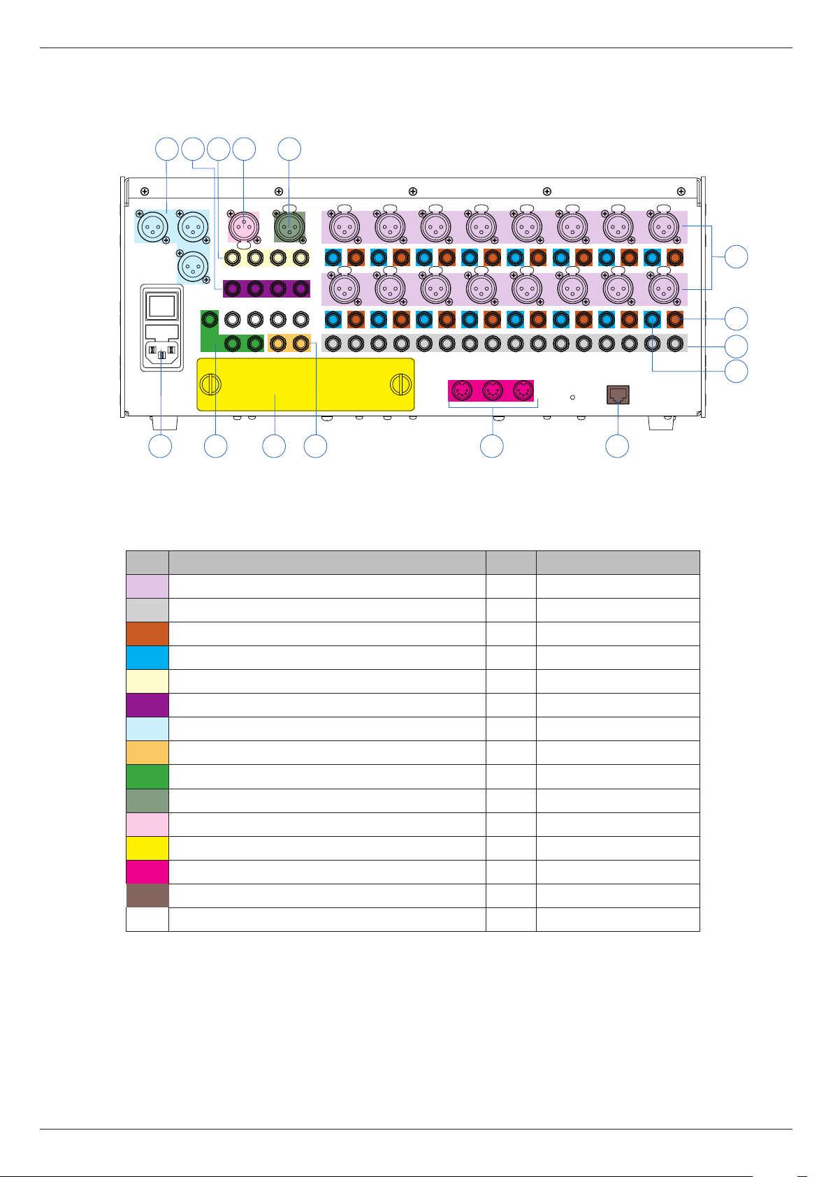
Rear view – connector panel
7 101156
LITTLITES
LEFTRIGHT
MONO
MON M
GP4
AUX 4
AUX 8
TALKBACK
GP3 GP2 GP1
AUX 3AUX 2AUX 1
AUX 7
AUX 6
MON LMON R
TAPE L OUTTAPE R OUT
CH 15
INSDO
AUX 5
INSDO
ST R8 ST L7ST R7 ST L6ST R6 ST L5ST R5 ST L4ST R4 ST L3ST R3 ST L2ST R2 ST L1ST R1
CH 13 CH 11 CH 9 CH 7 CH 5 CH 3CH 1
INSDO
INSDO
ST L8
INSDO
INSDO
INSDO
INSDO
IN OUT
MIDI
THRU
INSDO
INSDO
INSDO
INSDO
812 13 1415 9
* shown without optional CDC RACK interface installed
No. Connection Qty. Marking
1 Mic/line inputs 16 CH 1-16
2 Stereo line inputs 16 ST 1-8
3 Channel direct outputs (one only indicated) 16 DO
INSDO
INSDO
ETHERNET
INSDO
CH 2CH 4CH 6CH 8CH 10CH 12CH 14CH 16
INSDO
1
3
2
4
4 Channel insert send/returns (only one indicated) 16 INS
5 Group outputs 4 GP 1-4
6 Aux send outputs 8 AUX 1-8
7 Stereo master outputs: L, R and mono sum 3 LEFT, RIGHT, MONO
8 Stereo tape outputs 2 TAPE OUT, L & R
9 Monitor outputs: L, R and mono sum 3 MON L, R, M
10 Talkback mic input 1 TALKBACK
11 DC output for console lamp 1 LAMP 12V
12 Expansion port* 1 -
MIDI ports 3 MIDI IN, THRU, OUT
13
14 Ethernet network port 1 ETHERNET
15
IEC mains connector, fuse and AC power switch 1 -
* shown without optional CDC RACK interface installed
Revision 1 2012-13 CDC FOUR
Page 15

Connector details
This section provides electrical details of the CDC FOUR’s inputs and outputs.
The tables at the end of this section, referred to in each connector description,
summarise wiring details.
1. Mic/line inputs 1-16 - Neutrik® Combo A connectors. These sockets accept
either a 3-pin XLR male connector or a ¼” (6.35 mm) 3-pole (TRS) jack plug. The
sensitivity of the XLR input is suitable for microphones, while the jack input, which
has an 18 dB pad, is intended for line level sources. The inputs are electronically
balanced with an impedance of 1.2k ohms (mic) or 10k ohms (line). Nominal input
level at the XLR (with gain control at minimum) is 0 dBu; maximum input level
is +21 dBu. (Note that Cadac dene 0 dBFS to be equivalent to +21 dBu in the
CDC FOUR). 48 V phantom power is available at the XLR pins of this connector,
switchable from the channel strip.
The mic/line inputs should be wired as per Table A (XLR connectors) or as per
Table B (jack plugs).
15
2. Stereo line inputs 1-8 – eight pairs of ¼” (6.35 mm) 3-pole (TRS) jack sockets
(separate L and R inputs). Intended for connection to the line outputs of external
stereo equipment, including outboard FX processors and stereo tape returns.
The inputs are electronically balanced with an impedance of 10k ohms. Nominal
input level is 0 dBu; maximum input level is +21 dBu.
The stereo line inputs should be wired as per Table B.
3. Direct outputs 1-16 – pre-fade outputs from each of the 16 mono mic/line
channels. The outputs are electronically balanced on ¼” (6.35 mm) 3-pole (TRS)
jack sockets, and have a maximum output level of +21 dBu.
The direct outs should be wired as per Table B.
4. Channel inserts 1-16 – send and return insert points in each mono mic/line
channel. The send and return are both unbalanced, and have a maximum level of
+10 dBu. The connectors are ¼” (6.35 mm) 3-pole (TRS) jack sockets.
The inserts should be wired as per Table C.
5. Group outputs 1-4 – post-fade outputs of the four audio subgroups. Outputs
are electronically balanced on ¼” (6.35 mm) 3-pole (TRS) jack sockets, and have
a maximum output level of +21 dBu.
The group outputs should be wired as per Table B.
6. Aux sends 1-8 – the outputs of the mixer’s eight auxiliary busses. Every
channel can send pre- or post-fade to each Aux buss, and each Aux buss has a
master level. The Aux busses can be used as sends to external FX equipment
(normally pre-fade), or as performers’ foldback (normally post-fade). The outputs
are electronically balanced on ¼” (6.35 mm) 3-pole (TRS) jack sockets, and have
a maximum output level of +21 dBu.
The Aux sends should be wired as per Table B.
Revision 1 2012-13CDC FOUR
Page 16

16
7. Master outputs – the main outputs of the mixer. Three XLR male connectors
are provided: for left and right channels, and a mono sum of left and right
(L+R) - 6dB. The outputs are electronically balanced, and have a maximum
output level of +21 dBu.
The master outputs should be wired as per Table A.
8. Tape outputs – a secondary, buffered set of master outputs on ¼” (6.35 mm)
3-pole (TRS) jack sockets, intended to facilitate connection of a stereo recording
device. The signals at the L/R Tape Out connectors are identical to those at the
L/R Master Outputs [7] above, and are post the master fader and mute. There
is no equivalent mono sum output. The outputs are electronically balanced, and
have a maximum output level of +21 dBu.
The Tape outputs should be wired as per Table B.
9. Monitor outputs - the mixer’s monitor outputs. Three ¼” (6.35 mm) 3-pole
(TRS) jack sockets provide stereo monitoring, or a mono sum of left and right.
The stereo outputs are useful in a recording situation, but the same signal is
available for use in live sound at a dedicated headphone output under the front
armrest, with a separate level control. The mono sum output can also be used
in live sound situations to feed an engineer’s local wedge monitor. The monitor
source may be selected to be the master outputs, the PFL/AFL system or the
stereo tape return. The rear panel outputs are electronically balanced, and have
a maximum output level of +21 dBu.
The monitor outputs should be wired as per Table B.
10. Talkback mic – a 3-pin female XLR connector on the rear panel for a
dedicated dynamic mic or connection to a comms system.
The talkback mic should be wired as per Table A.
11. Console lamp – a 3-pin female XLR for connection of a gooseneck lamp to
provide console illumination.
12. Expansion port – this may be tted with an interface card for the CDC RACK
expansion stagebox; this uses a dedicated CADAC digital multichannel protcol.
13. MIDI ports – standard MIDI In, Out and Thru connectors
14. Ethernet port – RJ45 connector for software updates
15. AC mains - see “Power supply matters” on page 12 for wiring details.
Revision 1 2012-13 CDC FOUR
Page 17

Table A*
Pin Connection
1 Screen
2 Signal ‘hot’ (phase)
3 Signal ‘cold’ (antiphase)
Table B*
Pin Connection
Tip Signal ‘hot’ (phase)
Ring Signal ‘cold’ (antiphase)
Sleeve Screen
Table C
17
Pin Connection
Tip Send
Ring Return
Sleeve Screen (common)
* See the Appendix for information about connecting the CDC-FOUR to unbalanced sources and
destinations.
Revision 1 2012-13CDC FOUR
Page 18

18
Block Diagram
STEREO LR
AUX 1-8
FX 1&2
GROUP 1-4
AFL LR
PFL
Aux Output (TRS)
Group Output (TRS)
Monitor Output Left (TRS)
Headphone Output (TRS)
Monitor Output Right (TRS)
Monitor Output Mono (TRS)
Monitor Outputs
Stereo Output Right (XLR)
Mono Output (XLR)
Stereo Output Left (XLR)
Tape Output Left (TRS)
Tape Output Right (TRS)
Stereo Outputs
Internal mix busses
CDC FOUR - Basic Block Diagram
Mono Inputs 1-16 Aux Outputs 1-8
Mono Input (XLR)
Direct Output (TRS)
Insert Send/Return (TRS)
Stereo Inputs 1-8 Group Outputs 1-4
Stereo Input Left (TRS)
Stereo Input Right (TRS)
Internal FX Returns 1 & 2
FX Returns 1 & 2 (Internal)
Revision 1 2012-13 CDC FOUR
Page 19

Fundamentals
Although the CDC FOUR control surface and operating system has been
designed to retain the familiarity and facilities of an analogue console, there are a
number of important aspects of its operation which differ markedly from analogue
mixers. These include the following concepts:
• Assignability - a single channel strip whose controls can be assigned to any
of the internal signal channels;
• Layers – the faders can be switched to control another set of channels or
groups, resulting in a small control surface for a large conguration mixer;
• TFT screen – most of the mixer’s controls and statuses are accessible
through the built-in display as well as by using hardware controls; some mixer
functions are only available via the screen;
• Soft keys – various controls whose functions vary depending on the current
state of the display, or of other mixer settings.
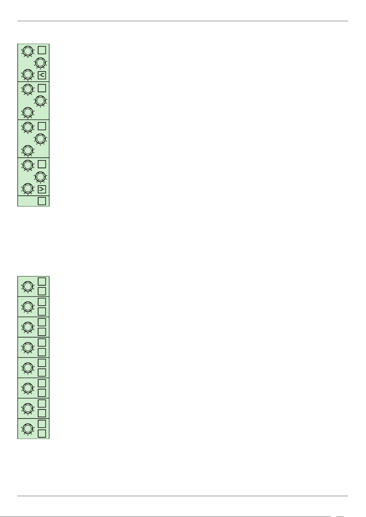
Central Assignment Module
19
CENTRAL ASSIGNMENT MODULE
-
+
48V
TRIM
-
REV
+
HPF
HPF
GATE
-
+
THR
COMP
-
+
THR
20:11:1
AUT
RAT
-
+
VIN
LVL
LIM
-
+
THR
DLY
SmS
BYP PST
HI LO
FREQ
HF
WN
Q
HI LO
FREQ
HMF
WN
IN
Q
HI LO
FREQ
IN
LMF
WN
Q
HI LO
FREQ
IN
LF
WN
IN
Q
AUX 1
0
IN
-
+
dB
AUX 2
0
AUX 3
IN
0
-
+
dB
AUX 4
0
IN
AUX 5
0
-
+
dB
AUX 6
0
IN
AUX 7
0
-
+
dB
AUX 8
0
EQ
IN
FX 1
0
ON
∞
PRE
∞
PRE
∞
PRE
∞
PRE
∞
PRE
∞
PRE
∞
PRE
∞
PRE
FX 2
0
ON
0
ON
3
6
9
12
ON
15
18
24
36
ON
54
LRGR
12
3
ON
LR
LR
ON
PAN
ON
∞
PRE
∞
PRE
SOLO
MUTE
The Central Assignment Module (CAM) is essentially a single,
ON
fully-featured channel strip, such as would be found on an
analogue mixer. The obvious differences are that potentiometers
ON
are replaced by continuous (360°) rotary encoders, and the push-
buttons are electronically latching and internally illuminated. The
0
encoders have a “press” function; turning the encoder knob while
3
pressing it in allows a ner degree of parameter adjustment. The
6
9
use of rotary encoders means that the value of the parameter
12
15
which the control varies is not related to the physical position
18
21
of the knob – in fact, the knobs do not have a pointer of any
GT
LIM
kind. Another implication of this system is that all the channel
parameters have default values which have nothing to do with
4
knob positions; these values can be regarded collectively as the
“initial state” of the channel. The actual value of each parameter
is available from the TFT display; this topic is covered in greater
IN
detail under “Screen displays”, see page 25.
The CAM controls the mixer’s DSP section, and is used to set the
channel parameters for the following mixer sections:
• All mono mic/line channels
• Stereo inputs 1-8
• Subgroups 1-4
• Aux. sends 1-8
• FX returns 1 and 2Note that unlike an analogue mixer, many of the channel
facilities found on an input channel strip are available to the output sections
of the CDC FOUR. Furthermore, there is no signicant difference in the
facilities available to stereo line input channels compared to mono mic/line
input channels.
However, it should be noted that not every channel facility is available to all types
of signal channel. The exceptions are noted in a later section of the manual, see
“Audio channel descriptions” on page 31.
Revision 1 2012-13CDC FOUR
Page 20

20
SEL
SOLO
MUTE
CH 1
CH 17
CH 33
+
-
+
TRIM
-
+
HPF
GATE
-
+
THR
COMP
-
+
THR
20:11:1
RAT
-
+
LVL
LIM
-
+
THR
DLY
SmS
BYP PST
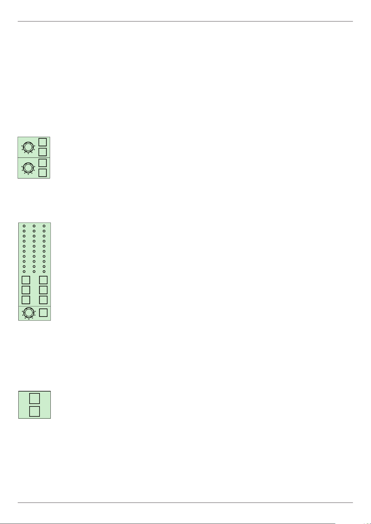
The SEL button
Each fader (except the stereo master) has a SEL button in addition to the usual
MUTE and SOLO. The channel for which the CAM is active is selected by
pressing SEL. Only one SEL button can be selected at a time.
Thus, if the SEL button above Fader 5 is pressed, the CAM will adjust the
parameters of whatever signal is currently assigned to that fader. (Note that each
fader, and hence each SEL button, may be assigned to one of up to ve possible
10
5
0
signals within the mixer. This concept is discussed further under “Layers”, see
page 23.)
The controls on the CAM are now discussed in more detail:
Input stage:
48V
REV
HPF
TRIM - input gain trim.
48v – phantom power at the mic input.
REV – phase reverse.
HPF – variable-frequency high-pass lter.
HPF – high-pass lter frequency.
Dynamics section:
IN
GATE: THR – noise gate threshold.
GATE: IN – noise gate in/out.
IN
AUT
VIN
IN
COMP: THR – compressor threshold.
COMP: RAT – compressor ratio.
COMP: LVL – compressor gain make-up.
COMP: IN – compressor in/out.
COMP: AUT – sets compressor attack/release times automatically
IN
COMP: VIN – selects “vintage” compressor algorithm.
LIM: THR – limiter threshold.
LIM: IN – limiter in/out.
BYP – dynamics section in/out.
PST – dynamics section post-EQ.
DLY
SmS
IN
Delay section:
DLY – delay time.
DLY: IN – delay in/out.
Revision 1 2012-13 CDC FOUR
Page 21
21
HI LO
FREQ
HF
WN
Q
HI LO
FREQ
HMF
WN
Q
HI LO
FREQ
LMF
WN
Q
HI LO
FREQ
LF
WN
Q
IN
-
+
dB
EQ Section:
HF: IN – HF EQ in/out.
HF: FREQ – EF EQ frequency.
HF: GAIN – HF EQ cut/boost.
IN
-
+
dB
HF: Q – HF EQ Q setting.
HF Shelf – HF EQ bell/shelf switch.
HMF: IN – HMF EQ in/out.
IN
-
+
dB
HMF: FREQ – HMF EQ frequency.
HMF: GAIN – HMF EQ cut/boost.
HMF: Q – HMF EQ Q setting.
LMF: IN – LMF EQ in/out.
IN
-
+
dB
LMF: FREQ – LMF EQ frequency.
LMF: GAIN – LMF EQ cut/boost.
LMF: Q – LMF EQ Q setting.
EQ
IN
LF: IN – LF EQ in/out.
LF: FREQ – LF EQ frequency.
LF: GAIN – LF EQ cut/boost.
AUX 1
AUX 2
AUX 3
AUX 4
AUX 5
AUX 6
AUX 7
AUX 8
LF: Q – LF EQ Q setting.
LF Shelf – LF EQ bell/shelf switch.
EQ IN – EQ section in/out.
0
ON
∞
PRE
0
ON
∞
PRE
0
ON
∞
PRE
0
ON
∞
PRE
0
ON
∞
PRE
Aux Sends:
AUX 1 – Aux. 1 send level.
AUX 1: ON – Aux. 1 on/off.
AUX 1: PRE – Aux. 1 pre/post.
AUX 2 – Aux. 2 send level.
AUX 2: ON – Aux. 2 on/off.
AUX 2: PRE – Aux. 2 pre/post.
AUX 3 – Aux. 3 send level.
AUX 3: ON – Aux. 3 on/off.
AUX 3: PRE – Aux. 3 pre/post.
0
ON
∞
PRE
0
ON
∞
PRE
0
ON
∞
PRE
AUX 4 – Aux. 4 send level.
AUX 4: ON – Aux. 4 on/off.
AUX 4: PRE – Aux. 4 pre/post.
AUX 5 – Aux. 5 send level.
AUX 5: ON – Aux. 5 on/off.
AUX 5: PRE – Aux. 5 pre/post.
AUX 6 – Aux. 6 send level.
AUX 6: ON – Aux. 6 on/off.
Revision 1 2012-13CDC FOUR
Page 22
22
AUX 6: PRE – Aux. 6 pre/post.
AUX 7 – Aux. 7 send level.
AUX 7: ON – Aux. 7 on/off.
AUX 7: PRE – Aux. 7 pre/post.
AUX 8 – Aux. 8 send level.
AUX 8: ON – Aux. 8 on/off.
AUX 8: PRE – Aux. 8 pre/post.
FX 1
0
ON
∞
PRE
FX 2
0
ON
∞
PRE
0
3
6
9
12
15
18
24
36
54
LRGR
12
3
LR
LR
PAN
0
3
6
9
12
15
18
21
GT
LIM
4
IN
Internal FX Sends:
FX 1 – FX buss 1 send level.
FX 1: ON – FX 1 on/off.
FX 1: PRE – FX 1 pre/post.
FX 2 – FX buss 2 send level.
FX 2: ON – FX 2 on/off.
FX 2: PRE – FX 2 pre/post.
Routing and metering section:
1 – Group 1 routing button.
2 – Group 2 routing button.
3 – Group 3 routing button.
4 – Group 4 routing button.
L – stereo buss (left) routing button.
R – stereo buss (right) routing button.
PAN – channel pan control.
PAN: IN – Group panning in/out.
L METER – channel bargraph meter (left).
R METER – channel bargraph meter (right).
GR METER – dynamics section gain reduction bargraph meter.
GT – noise gate active LED.
LIM – limiter active LED.
SOLO
Mute and Solo:
SOLO – channel PFL/AFL/SIP solo button.
MUTE
Revision 1 2012-13 CDC FOUR
MUTE – channel mute button.
Page 23
Layers
On an analogue mixer, the necessity for every channel (input or output) to have
its own set of controls and electronic hardware inevitably means that the physical
size of the mixer becomes proportional to the number of channels. An analogue
mixer with many inputs and outputs has a very large “footprint”.
This relationship may be dispensed with in a digital mixer, which allows a small
control surface to control large mixer congurations.
On the CDC FOUR, in 19” of control surface width, sixteen faders can control
up to 48 mic/line and 8 stereo inputs, plus eight Aux sends, eight VCA masters,
two internal FX returns and four output groups. This is achieved by arranging all
these various fader-controlled channels into ve* layers. Only one layer at a time
is active; the faders, with their associated MUTE, SOLO and SEL buttons control
the sixteen channels in that layer.
NOTE: The red MASTER fader always controls the main stereo output – it is not
part of any layer.
23
LAYER SELECT
CHNS
1 - 16
CHNS
VCA
The active layer is selected by the ve LAYER SELECT buttons ([7] on “Top view
CHNS
CHNS
33 - 48
17 - 32
ST
OUTPUTS
- control surface” on page 13).
The rst three layers make mic/line inputs 1-16, 17-32 and 33-48 respectively
available to the fader set. The layers corresponding to mic/line inputs 17 and
above will only be operative if the CDC RACK stagebox is connected to the mixer.
The fader assignments for the mic/line input layers are printed on the fader panel
above the faders.
The remaining two layers assign a combination of stereo inputs, VCA masters,
group outputs, Aux sends and FX masters to the fader set. The fader assignments
for these layers are printed on the fader panel below the faders.
* The faders may also be assigned to control the 1/3-octave graphic equaliser available to the main
stereo output; this effectively consitutes two additional layers.
Revision 1 2012-13CDC FOUR
Page 24

24
The table below summarises the signal which each fader controls in each layer:
LAYER SELECT BUTTON
FADER CHNS 1-16 CHNS 17-24 CHNS 33-48 ST CHNS VCA OUTPUTS
1 Mic/line input 1 Mic/line input 17 Mic/line input 33 Stereo input 1 Output group 1
2 Mic/line input 2 Mic/line input 18 Mic/line input 34 Stereo input 2 Output group 2
3 Mic/line input 3 Mic/line input 19 Mic/line input 35 Stereo input 3 Output group 3
4 Mic/line input 4 Mic/line input 20 Mic/line input 36 Stereo input 4 Output group 4
5 Mic/line input 5 Mic/line input 21 Mic/line input 37 Stereo input 5 Aux Send Master 1
6 Mic/line input 6 Mic/line input 22 Mic/line input 38 Stereo return 1 Aux Send Master 2
7 Mic/line input 7 Mic/line input 23 Mic/line input 39 Stereo return 2 Aux Send Master 3
8 Mic/line input 8 Mic/line input 24 Mic/line input 40 Tape return Aux Send Master 4
9 Mic/line input 9 Mic/line input 25 Mic/line input 41 VCA master 1 Aux Send Master 5
10 Mic/line input 10 Mic/line input 26 Mic/line input 42 VCA master 2 Aux Send Master 6
11 Mic/line input 11 Mic/line input 27 Mic/line input 43 VCA master 3 Aux Send Master 7
12 Mic/line input 12 Mic/line input 28 Mic/line input 44 VCA master 4 Aux Send Master 8
13 Mic/line input 13 Mic/line input 29 Mic/line input 45 VCA master 5 FX Master 1
14 Mic/line input 14 Mic/line input 30 Mic/line input 46 VCA master 6 FX Master 2
15 Mic/line input 15 Mic/line input 31 Mic/line input 47 VCA master 7 -
16 Mic/line input 16 Mic/line input 32 Mic/line input 48 VCA master 8 -
The SEL button for each fader - and hence the entire Central Assignment Module
– follows the currently selected layer. Thus pressing the SEL button above Fader
5 will assign the CAM to mic/line input 5 when the layer CHNS 1-16 is active, but
to mic/line input 21 if the next layer, CHNS 17-32, is active, and to stereo input 5
if the layer ST CHNS VCA is active.
Every channel parameter for all the channels in a layer retains its last value when
the active layer is changed. This means that all levels, EQ settings, sends, etc.,
adjusted for a particular input will stay exactly as they are when you change to
a different layer. Although the fader set and CAM are now assigned to mic/line
inputs 17-32, it is possible to check and adjust parameters in mic/line inputs 1-16
– or any other layer – through the TFT display. Note that as the active layer is
changed, the motorised faders will automatically move to the correct positions for
the new layer.
Revision 1 2012-13 CDC FOUR
Page 25

CENTRAL CONTROL MODULE
USB
METERS
SCENE
FX
25
Screen displays - overview
The TFT screen in the Central Control Module displays various information about
the current status of the mixer. The screen may be switched to display any one of
several pages, each of which is concerned with a particular set of mixer functions.
There are six pages available, selected by the page select buttons to the left of
the display:
CHN: this is the default view.
ROUTE
SYSTEM
CHN
The screen shows a representation of a single channel strip. Every control on
the CAM has a “virtual” equivalent on the display, and the page layout follows the
conventional signal ow through a channel. It is divided into ve vertical strips, the
rst four of which follow the layout of controls on the CAM. The fth (rightmost)
page strip shows the channel fader and VCA assignment.
The on-screen display always follows the SEL and LAYER selection; thus the
screen provides conrmation of the control settings for the currently selected
channel.
Because the rotary controls in the CAM are 360° encoders, their physical position
is not an indication of the parameter value (as would be the case on an analogue
mixer). However, the Channel page shows all current parameter values. Switch
settings are displayed in textual format and rotary controls are represented as
“analogue” 300° potentiometers, with the actual parameter value alongside in
text.
Revision 1 2012-13CDC FOUR
Page 26
26
CENTRAL CONTROL MODULE
USB
METERS
SCENE
FX
ROUTE
SYSTEM
CHN
SYSTEM:
CENTRAL CONTROL MODULE
USB
METERS
SCENE
FX
ROUTE
SYSTEM
This page provides access to various console functions that do not have
equivalent hardware controls. These include line-up oscillator functions, talkback
routing control, monitor controls and solo system control. The System page also
includes virtual copies of the monitor and headphone level and mute controls,
and the PFL/AFL meters.
See “System” on page 62 for more information.
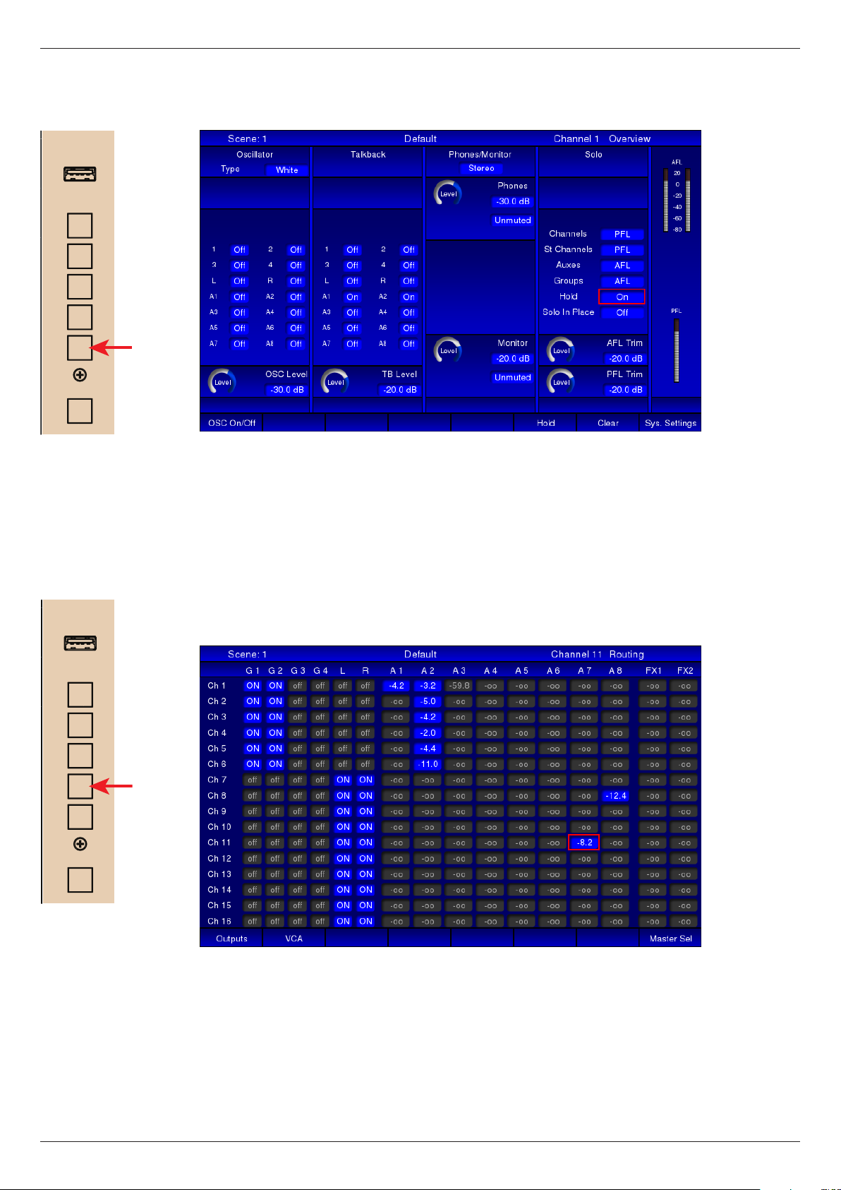
ROUTE: the Routing page shows a “global” view of all routing assignments for
the current layer.
CHN
In addition to the settings of the group and stereo buss routing buttons, the page
also shows the send levels to each of the eight Aux busses and the two FX
busses.
See “Routing” on page 51 for more information.
Revision 1 2012-13 CDC FOUR
Page 27

CENTRAL CONTROL MODULE
USB
METERS
SCENE
FX
ROUTE
SYSTEM
CHN
27
FX: this page allows control of the CDC FOUR’s two internal FX processors.
CENTRAL CONTROL MODULE
USB
METERS
SCENE
FX
ROUTE
SYSTEM
The processors’ inputs are two “virtual busses”, FX1 and FX2, which can be
used in the same way as any of the Aux sends. The outputs may be routed to the
stereo output and their FX return levels controlled by faders 13 and 14 when the
OUTPUTS layer is active.
See “FX processing” on page 58 for more information.
SCENE: the Scene page is concerned with the CDC FOUR’s scene memory.
CHN
The CDC FOUR is equipped with a “snapshot”-style scene automation system,
which allows all current console parameters (both switch and rotary control
settings) to be saved as a Scene. Scenes may be named and assembled into
a performance sequence off-line, and then, during performance, recalled by
a single button press. This allows the mixer to easily and seamlessly switch
between complex set-ups to suit, for example, successive scenes of a stage
drama, or different musical numbers. The motorised faders form part of the scene
memory, and when a Scene is recalled, will assume the position they were in
when the Scene was saved.
See “Scene Control” on page 67 for more information.
Revision 1 2012-13CDC FOUR
Page 28

28
CENTRAL CONTROL MODULE
USB
METERS
SCENE
FX
ROUTE
SYSTEM
CHN
METERS: this page gives a “global” overview of up to 50 bargraph meters
simultaneously.
The page is divided in to three areas horizontally. The upper area has 16 meters
showing the signal level in each of the on-board mic/line channels; the middle
area has 8 dual meters showing the signal level in the eight stereo input channels;
the lower area has 12 meters showing the signal levels of the four Groups and
eight Aux sends, and 3 dual meters showing the FX return levels and the stereo
master signal. Metering may be selected pre- or post-fade from the screen.
See “Metering” on page 53 for more information.
Revision 1 2012-13 CDC FOUR
Page 29

Screen navigation
As channel parameters can be varied both from the TFT display or the CAM, a
simple system of screen navigation is provided. On the CHN page, the virtual
control corresponding to the last-adjusted control on the CAM is highlighted by a
red rectangular cursor (see left).
The cursor moves around the screen as the various channel controls are adjusted.
Any channel parameter may be adjusted from the screen by moving the cursor to
the appropriate virtual control with the four “arrow” keys below the display.
CONTROL
DEL RCLSVE COPY PASTE
29
PN
ENTER
In general, the “up” and “down” keys will move the cursor vertically within the
current strip, and the “left” and “right” keys will move it either to adjacent controls
in the same strip or into the next strip. With the desired virtual control highlighted,
its parameter value may be adjusted by the ADJUST knob.
Note that the ADJUST knob is used for both “rotary” functions (EQ adjustments,
send levels, etc.) and switch functions (send pre/post, lters in/out, etc.). Rotary
functions are represented on-screen by a 300° arc, which changes colour clockwise
from blue to white as the knob is turned. The actual numeric parameter value
is displayed alongside. Switch functions are represented by small rectangular
“buttons”. Status is either indicated by an integral “virtual LED”, which illuminates
(white) when the switch is On, or by the text label on the button changing.
If a section of the channel processing is bypassed (e.g., gate, compressor, EQ,
etc.), the screen display corresponding to the section is “dark” (greyed-out) to
indicate it is not available. See left for example; only AUX 1 and AUX 2 are active.
The same screen navigation principle applies to the other screen pages (with the
exception of the METERS page, which has no controls).
Revision 1 2012-13CDC FOUR
Page 30

30
USB
CENTRAL CONTROL MODULE
U1
U2
U3
U4
METERS
SCENE
FX
Softkeys
The CDC FOUR has a set of eight “soft” keys below the screen display. These
have no printed legends; each button’s function is indicated on the TFT screen
immediately above.
ROUTE
SYSTEM
CHN
TALK
ADJUST
+
-
In general, the softkeys bring up an additional display page, which presents a
section of the current channel in greater detail – e.g., EQ or Dynamics.
Softkeys with a blank legend space above them on the screen have no function.
Revision 1 2012-13 CDC FOUR
Page 31

Audio channel descriptions
Input channel
A detailed block diagram of the Input channel may be found in the Appendix on
page 74.
The CDC FOUR can handle up to 48 mono mic/line inputs, divided into three
blocks of 16. The inputs to Channels 1 to 16 are on the rear panel; those for
Channels 17 to 48 are only available if the CDC RACK stagebox is in use.
The CAM and the TFT display are made active for a mic/line input when one
of the rst three layers is selected (CHNS 1-16, CHNS 17-24, CHNS 33-48).
The active channel is that whose SEL button is illuminated. If no CDC RACK is
connected, the two buttons CHNS 17-32 and CHNS 33-48 will be inoperative.
31
MIC 1
60 0
Mic pre-amps
Mic/line inputs 1 to 16 are equipped with high-quality, low-noise mic pre-amps.
This design uses premium ICs and exhibits wide dynamic range and excellent
CMRR. The gain control operates in the analogue domain, and has a range of
0 to +60 dB.
0
3
6
9
12
15
18
24
36
54
Meters
The 10-segment LED bargraph meter shows either the pre-fade or post-fade
signal in the channel, as selected by the Pre/Post switch on the METERS screen
page. The sixteen xed meters (below the mic pre-amp gain controls) change
source with layer selection, thus can be used to monitor stereo inputs, group
and Aux sends, etc., as well as mic/line inputs. When the ST CHNS VCA layer is
selected, the odd numbered meters show the left legs of the stereo channels, and
the even-numbered the right.
The lowest LED (coloured green) illuminates at -54 dB and can be considered
a “signal present” LED. The top three LEDs (coloured red) illuminate at -6 dB,
-3 dB and 0 dB respectively. Note that the 0 dB reference for these levels is
0 dBFS (digital clipping). Thus the input gain should be adjusted so that the top
LED never illuminates.
Revision 1 2012-13CDC FOUR
Page 32

32
+
-
GATE
THR
IN
Remainder of input channel - CAM/screen control
All other input channel functions are controlled from either the CAM or the screen.
In CHN mode, the screen displays a virtual channel strip with a full set of controls
which may be adjusted using the ADJUST knob.
TRIM
HPF
GATE
THR
-
+
48V
-
REV
+
HPF
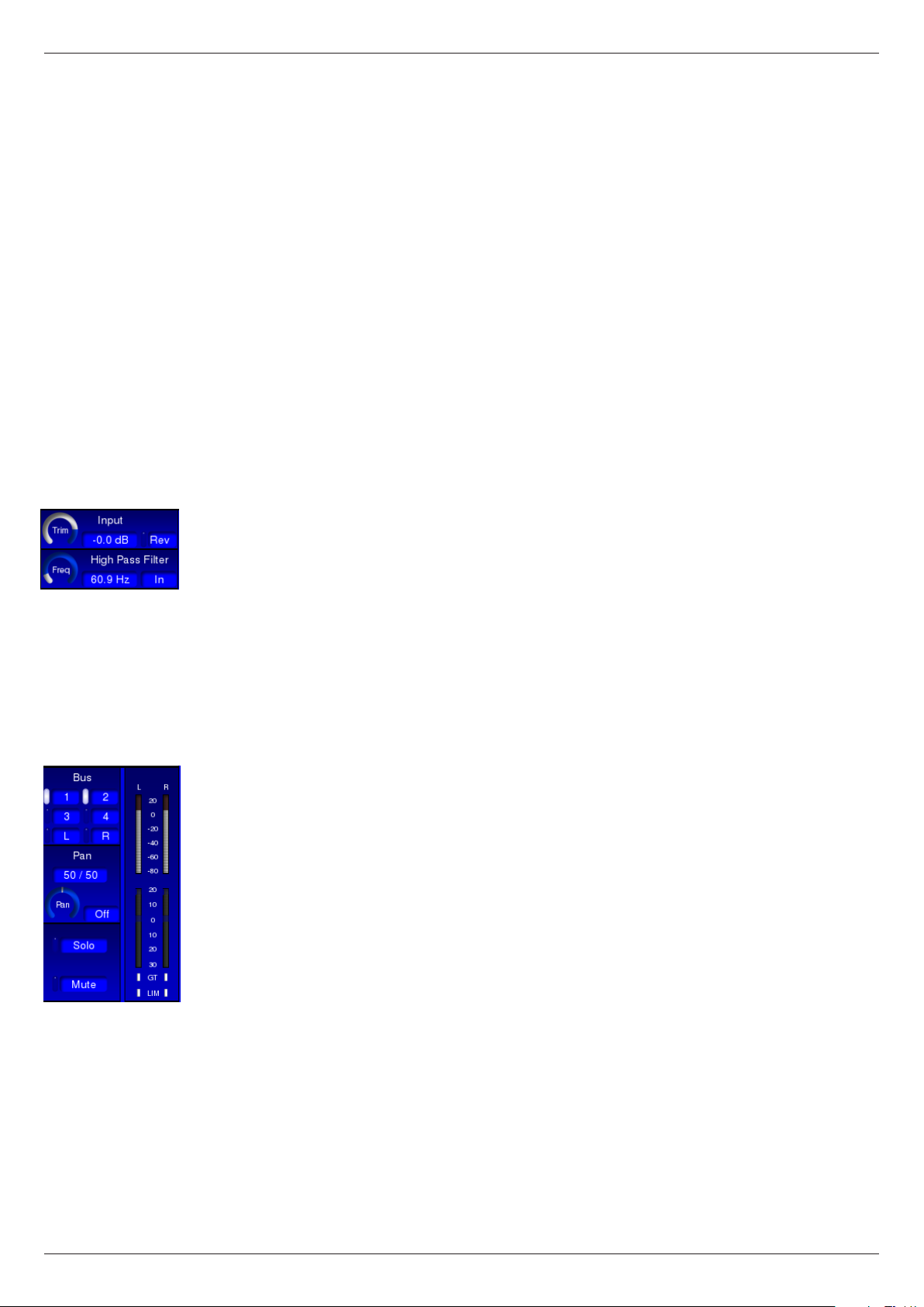
Input stage:
TRIM - input gain trim, range -48 to +12 dB. Default setting is 0 dB.
48v – enables 48 V phantom power at the mic input. Default is Off.
REV – phase reverse switch. Default is Off.
HPF (button) – enables the variable-frequency high-pass lter. Default is Off.
HPF (rotary) – adjusts the cut-off frequency of the high-pass lter. Range is 14 Hz
to 400 Hz, slope 12 dB/oct. Default setting is the minimum: 14 Hz.
-
+
IN
Noise gate:
THR – adjusts the threshold of the channel’s noise gate in the range from “off”
(below -74.9 dB) to -20 dB. Default setting is -60 dB. When the gate is in circuit,
signals below the threshold level will be rejected; the signal level needs to exceed
the threshold in order to open the gate.
IN – switches the noise gate into the signal chain. Default is Out.
NOTE: Additional Gate parameters are available from the Dynamics Details
screen page – see “Dynamics detail” on page 54.
COMP
+
THR
20:11:1
RAT
+
LVL
-
IN
AUT
-
VIN
Compressor:
THR – adjusts the threshold of the channel’s compressor in the range -48 dB to
0 dB. Default setting is -12 dB. Signals below the threshold will not be compressed. Signals above the threshold will have their levels reduced to a degree
determined by the ratio control (below).
RAT – adjusts the compression ratio between 1:1 to 20:1. Default setting is 1:1
(i.e., no compression). A compression ratio of 1:1 implies zero compression;
higher values will proportionately reduce the dynamic range of the signal, e.g., at
a setting of 2:1, signals 10 dB above the threshold will be compressed to be only
5 dB above the threshold.
LVL – adds gain to compensate for compressor action. Range is -12 dB to +12
dB. Default setting is 0 dB.
IN – switches the compressor into the signal chain. Default is Out.
AUT – in Auto mode, the compressor’s Attack and Release time constants are
not xed, but programme-dependent, and set by an algorithm which makes the
compressor’s action unobtrusive. In Manual mode, the time constants may be
adjusted from the Dynamics Detail page (see NOTE below).
Revision 1 2012-13 CDC FOUR
Page 33

DLY
SmS
+
-
+
-
+
-
+
-
20:11:1
LIM
THR
DLY
COMP
GATE
LVL
RAT
THR
THR
IN
IN
AUT
VIN
IN
IN
SmS
33
VIN – enables an alternative compressor algorithm which makes the compressor
act like a leveller, modelling the sound of certain vintage compressors.
NOTE: Additional Compressor parameters are available from the Dynamics
Details screen page – see “Dynamics detail” on page 54.
IN
Delay section:
DLY – the CDC FOUR allows an adjustable delay to be inserted in each signal
channel. Range 0 to 100 ms. Default setting is zero.
DLY: IN - switches the delay circuit into the signal chain. Default is Out.
BYP PST
Dynamics/Delay Global:
BYP - switches the complete dynamics section (gate, compressor and limiter)
and delay section in and out of the signal chain. Default is Out.
PST – the dynamics and delay sections can be pre- or post-EQ in the CDC FOUR.
Pressing PST inserts them after the equaliser. Default is Off (i.e., dynamics are
pre-EQ).
Revision 1 2012-13CDC FOUR
Page 34

34
+
-
HI LO
WN
FREQ
Q
HF
dB
IN
+
-
HI LO
WN
+
-
HI LO
WN
FREQ
Q
FREQ
Q
HMF
HF
dB
IN
IN
dB
+
-
HI LO
WN
+
-
HI LO
WN
+
-
HI LO
WN
FREQ
Q
FREQ
FREQ
Q
Q
HMF
HF
LMF
dB
IN
IN
IN
dB
dB
EQ Section:
The CDC FOUR’s equaliser is a 4-band parametric type, with bell-shelf switching
on the highest and lowest bands. The channel’s frequency response (EQ curve)
can be seen on the EQ detail page (see page 54).
IN – switches the HF section of the equaliser into circuit. Default is Out.
HI LO
FREQ
HF
WN
Q
HI LO
FREQ
HMF
WN
Q
IN
-
+
dB
FREQ – adjusts the frequency of the HF section of the equaliser. This will be the
centre frequency of a bell lter if the Shelf switch is set to Bell, and the turnover
frequency if it is set to Shelf. Range is 1.5 kHz to 15 kHz. Default setting is 1.5
kHz.
GAIN – allows 18 dB of cut or boost in the selected frequency band. Default
setting is 0 dB (at response).
Q – adjusts the bandwidth of a bell lter; Q range is 1.0 (wide) to 3.0 (narrow).
Default setting is 1.0. If the Shelf switch is On, the control is inoperative and is
removed from the screen display.
Shelf – switches the HF section of the equaliser between Bell and Shelving
modes. In Shelving mode, the EQ section acts as a “treble” control, and has a
xed slope of 6 dB/octave. Default is Bell.
IN
-
+
dB
IN – switches the HMF section of the equaliser into circuit. Default is Out.
FREQ – adjusts the frequency of the HMF section of the equaliser. The section is
always a Bell lter. Range is 400 Hz to 4 kHz. Default setting is 400 Hz.
GAIN – allows 18 dB of cut or boost in the selected frequency band. Default
setting is 0 dB (at response).
FREQ
LMF
FREQ
LF
HI LO
dB
WN
Q
HI LO
dB
WN
Q
Q – adjusts the bandwidth of the lter; Q range is 1.0 (wide) to 3.0 (narrow).
Default setting is 1.0.
IN
-
+
IN – switches the LMF section of the equaliser into circuit. Default is Out.
FREQ – adjusts the frequency of the LMF section of the equaliser. The section is
always a Bell lter. Range is 60 Hz to 600 Hz. Default setting is 60 Hz.
GAIN – allows 18 dB of cut or boost in the selected frequency band. Default
setting is 0 dB (at response).
Q – adjusts the bandwidth of the lter; Q range is 1.0 (wide) to 3.0 (narrow).
Default setting is 1.0.
IN
-
+
IN – switches the LF section of the equaliser into circuit. Default is Out.
FREQ – adjusts the frequency of the LF section of the equaliser. This will be the
centre frequency of a bell lter if the Shelf switch is set to Bell, and the turnover
frequency if it is set to Shelf. Range is 20 Hz to 200 Hz. Default setting is 20 Hz.
GAIN – allows 18 dB of cut or boost in the selected frequency band. Default
setting is 0 dB (at response).
Q – adjusts the bandwidth of a bell lter; Q range is 1.0 (wide) to 3.0 (narrow).
Default setting is 1.0. If the Shelf switch is On, the control is inoperative and is
removed from the screen display.
Revision 1 2012-13 CDC FOUR
Page 35
Shelf – switches the LF section of the equaliser between Bell and Shelving
+
-
HI LO
WN
+
-
HI LO
WN
+
-
HI LO
WN
+
-
HI LO
WN
FREQ
Q
FREQ
FREQ
FREQ
Q
Q
Q
HMF
HF
LMF
LF
dB
IN
IN
IN
IN
dB
dB
dB
modes. In Shelving mode, the EQ section acts as a “bass” control, and has a
xed slope of 6 dB/octave. Default is Bell.
35
AUX 1
AUX 2
AUX 3
AUX 4
AUX 5
AUX 6
AUX 7
AUX 8
EQ
IN
0
ON
∞
PRE
EQ IN – switches the entire 4-band EQ section into circuit. Default is EQ Out; in
this state, the entire EQ section of the CHN page is “dark”.
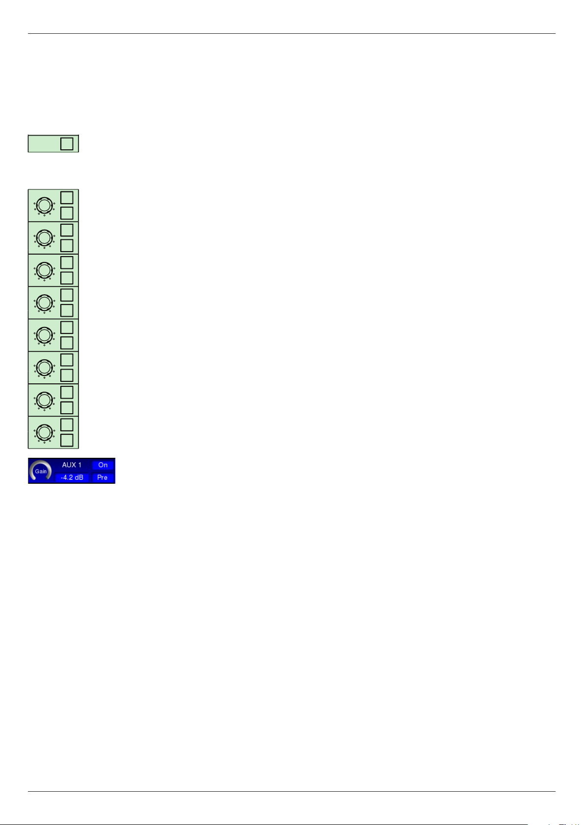
Aux Sends:
The CDC FOUR’s eight auxiliary sends are identical in operation. For brevity,
only Aux 1 is described:
0
ON
∞
PRE
0
ON
∞
PRE
0
ON
∞
PRE
0
ON
∞
PRE
0
ON
∞
PRE
0
ON
∞
PRE
0
ON
∞
PRE
AUX 1 – level control from the channel to Aux Buss 1. Range is – ∞ (i.e., off); then
-75 dB to 0 dB. Default is Off.
ON – unmutes the feed to Aux Buss 1. Default is Off.
PRE – default source for Aux. Sends is post-fade, but can be changed to pre-fade
with the PRE button. Both pre- and post-fade sends are post-Channel Mute.
The status of all eight Aux. sends for blocks of 16 input channels may be viewed
on the screen ROUTE page. See page 51.
Revision 1 2012-13CDC FOUR
Page 36

36
FX Sends:
FX 1
0
ON
∞
PRE
FX 2
0
ON
∞
PRE
0
3
6
9
12
15
18
24
36
54
LRGR
12
3
LR
LR
PAN
0
3
6
9
12
15
18
21
GT
LIM
4
IN
The CDC FOUR has two internal DSP-based effects processors, which provide
a selection of time-domain effects such as delay and reverb. The inputs to these
are additional sends, denoted FX1 and FX2, and the outputs are routed to the
main LR stereo buss or Groups 1 to 4 via two faders in the OUTPUTS Layer.
See “FX processing” on page 58 for full details.
The two FX sends are identical in operation. For brevity, only FX 1 is described:
FX 1 – level control from the channel to internal FX buss 1. This routes the signal
to FX processor 1. The level control’s range and default settings are the same as
the Aux. sends.
ON – unmutes the feed to FX Send 1. Default is Off.
PRE – default source for FX Send is post-fade, but can be changed to pre-fade
with the PRE button. Both pre- and post-fade sends are post-Channel Mute.
Routing and metering section:
The CDC FOUR has four mono group busses in addition to the main LR stereo
buss. The groups may either be used as subgroups into the main mix or as
additional outputs from the mixer. The usual set of routing buttons and odd/even
panning is provided.
1 - 4 – four buss select buttons which route the channel to Audio Groups 1 to 4
respectively.
L & R – two buss select buttons which route the channel respectively to the L and
R legs of the stereo master buss. Note that the pan control is always in circuit with
respect to the L & R busses.
PAN – allows the channel signal to be panned between odd-numbered busses
(and the L leg of the master buss) and even-numbered busses (and the R leg of
the master buss). Default is “centre” – i.e., equal signal levels are routed to the
selected busses. The adjacent IN button must be enabled for the pan control to
be active for the four groups; it is always operational across the main L/R buss.
IN – enables the PAN control for panning between odd- and even-numbered
groups. Default is Out; in this state, the signal in the channel is sent at equal level
to all busses selected by the routing buttons 1 to 4.
L & R METERS – two 10-segment LED bargraph meters indicating channel
signal level are tted in the CAM area. With mic/line channels, both L and R
meters give the same indication. The meters show the pre-fade (and hence prepan) signal level relative to 0 dBFS. The bottom LED is green and illuminates at
-54 dBFS, and thus acts as a “signal present” LED. The top three LEDs are red,
the uppermost indicating the digital peak level of 0 dBFS. The remainder of the
LEDs are yellow.
GR METER – an 8-segment LED bargraph meter indicating the instantaneous
gain reduction being applied by the dynamics section’s compressor.
GT – a red LED which illuminates when the channel’s Noise Gate is opened by
the signal exceeding the threshold.
Revision 1 2012-13 CDC FOUR
Page 37

LIM – non-operative for input channels.
Mute and Solo:
37
SOLO
MUTE
SOLO – routes the signal in the channel to the internal PFL or AFL busses,
to permit the signal to be monitored without otherwise interrupting the mixer’s
routings. The operation of the Solo system is controlled from the Solo Logic
section, see “Solo control” on page 63.
MUTE – mutes the signal in the channel. Note that all Aux. Sends are also muted,
but Insert Sends and Direct Outs remain active.
Note that the CAM’s MUTE and SOLO buttons have exactly the same function
as the fader block MUTE and SOLO buttons for the channel currently assigned
to the CAM (i.e., those immediately below whichever SEL button is currently
illuminated).
Revision 1 2012-13CDC FOUR
Page 38
38
Stereo inputs
A detailed block diagram of the Stereo Inputs may be found in the Appendix on
page 75.
The CDC FOUR has eight stereo line channels, with inputs on the rear panel.
The CAM and the TFT display are made active for a stereo channel when the
ST CHNS VCA layer is selected. The stereo channels are then controlled by
Faders 1 to 8, and that assigned to the CAM and TFT display is the one whose
SEL button is illuminated.
Analogue mixers generally offer a more limited set of controls on stereo channels
than on mono. This need not apply to a digital mixer, and on the CDC FOUR, a
stereo line channel has almost the same set of controls as a mono channel.
For this reason, only the differences from a mono channel are summarised
below. The description of the mono mic/line channel applies in all other respects.
Refer to Page 32 onwards for full details.
Input stage:
TRIM - input gain trim, range -48 to +12 dB. Default setting is 0 dB.
Phase reverse – reverses the phase in the left leg of the channel only.
Aux Sends:
In a stereo channel, a mono sum of left and right legs is fed to the auxiliary
busses. The send controls otherwise operate in an identical manner to those
in a mono channel. Post-fade sends are derived pre-balance control, but post-
Channel mute.
Routing and metering section:
The left and right legs of a stereo channel are fed to the L and R busses of the
main stereo mix via the pan control, which is recongured to operate as a stereo
balance control.
With the pan control IN button Off, pressing any of the group routing buttons 1
to 4 sends a mono sum of the left and right legs to that group; routing to multiple
groups will operate in the same way. If the pan IN button is On, stereo routing
to odd/even pairs of groups results. The stereo image set by the balance control
is maintained, with the left leg selectable to Groups 1 and 3, and the right leg to
Groups 2 and 4.
Pan – acts as a balance control; turning the control clockwise from the centre
position will attenuate the left leg of the channel but leave the right leg unaltered
in level. At the maximum, the left leg is fully attenuated. The opposite applies for
anticlockwise rotation.
Revision 1 2012-13 CDC FOUR
Page 39

Groups
A detailed block diagram of the Groups may be found in the Appendix on
page 76.
The CDC FOUR has four mono groups, with outputs on the rear panel. They may
be used either for recording or other external purposes, or the outputs may be
ignored, and they can form subgroups into the main stereo mix.
Some channel functions are absent from groups (relative to the input channels).
The differences from a mono channel are summarised below. The description of
the mono mic/line channel applies in all other respects. Refer to Page 32 onwards
for full details.
39
Input stage:
All input functionality is removed. The Input Trim, high-pass lter and phase
controls are inoperative and their virtual counterparts do not appear on-screen.
Noise gate:
The groups do not have noise gates. All noise gate controls are inoperative and
their virtual counterparts do not appear on-screen.
Limiter:
The groups’ dynamics sections have a dedicated limiter as well as the compressor
section tted to the input channels.
THR - adjusts the threshold of the group’s separate limiter section in the range
-40 dB to +21 dB. Default setting is +21 dB (i.e., no limiting).
IN - switches the limiter into the signal chain. Default is Out.
Aux Sends:
The groups do not have Aux Send facilities. All Aux Send controls are inoperative
and their virtual counterparts do not appear on-screen.
Revision 1 2012-13CDC FOUR
Page 40
40
FX Sends:
The groups cannot send to the internal FX processors. All FX Send controls are
inoperative and their virtual counterparts do not appear on-screen.
Routing and metering section:
Any of the four groups may be routed to the main LR stereo buss, permitting their
use as subgroups. The groups default with this routing enabled. The PAN control
is always in circuit, and with the control at its centre position (50/50, the default
value), the mono group signal feeds the left and right legs of the main stereo buss
equally, and is thus in the centre of the main stereo image. Full left-right panning
is possible, using either the PAN control on the CAM or via the screen using the
ADJUST control. However, the pan control IN button is disabled.
1 - 4 – the four group routing buttons 1 to 4 are not available to groups; thus it is
not possible to route a group to another group (or itself!).
L & R – a group may be routed to either the left or right legs of the main stereo
buss individually, though the setting of the PAN control will affect the level (i.e.,
routing to L and panning fully right will result in no signal).
Revision 1 2012-13 CDC FOUR
Page 41

VCA groups
Although the CDC FOUR, as a digital mixer, has no actual VCAs – these being a
purely analogue concept – the terminology is retained for reasons of familiarity.
The CDC FOUR allows the creation of up to eight “control groups”, which
operate in exactly the same way as VCA groups on an analogue mixer. Any input
channel (mono or stereo) may be assigned to any VCA group or combination
of VCA groups. The level of all the channels in the group may then be adjusted
simultaneously by a single fader.
The VCA master faders are available when the ST CHNS VCA layer is selected;
faders 9 to 16 are assigned for this purpose. Note that as VCA groups are entirely
“virtual”, they are not assigned to the CAM. When the ST CHNS VCA layer is
selected, pressing a SEL button above any of the VCA faders opens a dedicated
VCA screen page, which gives an overview of the VCA master fader settings.
41
Note that this page may also be viewed at any time by the use of Softkey 7,
which is available on all input and output pages.
VCA group assignment
Any mono or stereo input channel may be assigned to any combination of VCA
groups. The assignment is made via the display; there are no equivalent hardware
keys. The VCA group buttons are at the extreme right of the Channel page and
may be selected by moving the cursor to them with the navigation keys, and
operated by rotating the ADJUST knob.
Revision 1 2012-13CDC FOUR
Page 42

42
Levels within VCA groups
As with all layers, when the ST CHNS VCA layer is selected, faders 9 to 16
immediately move to their correct positions. If no adjustment of VCA master levels
have been made, this position will be at the 0 dB mark. The implication of this
is that simply assigning a channel to a VCA group does not alter its signal level
anywhere in the mixer. The level in the mix may now be adjusted in two places –
by the channel’s own fader or by the VCA master. The fader positions of the two
faders effectively “add” to dene the overall signal level. Thus if the channel fader
is at -6 dB and the VCA fader is set to -10 dB, the level of the channel in the mix
will be the same as it would if the channel fader were set to -16 dB without any
VCA assignment being made.
The relative levels of all the channels assigned to any one VCA group remain
unchanged; adjusting the VCA master alters the level of the whole set of
channels without disturbing their inherent mix. A common application is to assign
all the channels being used to mic a drum kit to a VCA group after a satisfactory
balance of the kit has been made. The VCA master fader will then alter the level
of the whole kit in the mix, without altering any the internal balance, or any stereo
imaging.
VCA Group Muting
A VCA group may be muted by pressing the MUTE button above the VCA master
fader. This mutes all the channels assigned to the group. A corresponding virtual
MUTE button is provided on the TFT VCA page. The individual channels’ MUTE
buttons – both the physical ones and the on-screen virtual buttons – illuminate to
conrm this.
Note that the SOLO button has no function for a VCA group.
Revision 1 2012-13 CDC FOUR
Page 43

Aux outputs
A detailed block diagram of the Aux 0utputs may be found in the Appendix on
page 77.
The CDC FOUR has eight auxiliary sends, with outputs on the rear panel. All
the sends are mono. They may be used for external FX sends, or for foldback
purposes.
The Aux Send channels have processing similar to that of the Groups; the main
difference is the absence of any routing. The differences from a mono channel
are summarised below. The description of the mono mic/line channel applies in
all other respects. Refer to Page 32 onwards for full details.
43
Input stage:
All input functionality is removed. The Input Trim, high-pass lter and phase
controls are inoperative and their virtual counterparts do not appear on-screen.
Noise gate:
The Aux Send channels do not have noise gates. All noise gate controls are
inoperative and their virtual counterparts do not appear on-screen.
Limiter:
The Aux Sends’ dynamics sections have a dedicated limiter as well as the
compressor section tted to the input channels.
THR - adjusts the threshold of the Aux send’s separate limiter section in the range
-40 dB to +21 dB. Default setting is +21 dB (i.e., no limiting).
IN - switches the limiter into the signal chain. Default is Out.
Revision 1 2012-13CDC FOUR
Page 44

44
Aux Sends:
It is not possible to send an Aux output to another Aux Send. All Aux Send controls
are inoperative and their virtual counterparts do not appear on-screen.
FX Sends:
The Aux outputs cannot send to the internal FX processors. All FX Send controls
are inoperative and their virtual counterparts do not appear on-screen.
Routing and metering section:
It is not possible to route an Aux output anywhere else, thus the routing buttons 1
to 4 and L & R are inoperative. As the sends are mono, the PAN controls are also
inoperative. MUTE and SOLO are still functional, however.
Revision 1 2012-13 CDC FOUR
Page 45

45
STEREO MASTER OUTPUT MODULE
0
3
6
9
12
15
18
24
36
54
LRGR
COMP
-
+
THR
20:11:1
RAT
LVL
LIM
THR
+
+
BYP
IN
AUT
-
VIN
-
IN
PST
0
3
6
9
12
15
18
21
GT
LIM
HI LO
FREQ
HF
WN
Q
HI LO
FREQ
HMF
WN
Q
HI LO
FREQ
LMF
WN
Q
HI LO
FREQ
LF
WN
Q
Stereo master
IN
-
+
dB
+
dB
+
dB
+
dB
A detailed block diagram of the Stereo master may be found in the Appendix on
page 78
The stereo master channel on the CDC FOUR differs from all the other channel
IN
types in several respects, most importantly, the absence of a SEL button, and the
-
provision of a dedicated set of controls. The controls and facilities on the Stereo
Master Output Module (SMOM) are very similar to those which the CAM provides
to the other channel types.
IN
-
The TFT screen can be selected to display the stereo master channel by pressing
Softkey 8 from any other page:
IN
-
EQ
IN
Derived outputs
The main stereo outputs from the left and right leg D-to-A converters in the stereo
master output channel are also routed internally to the stereo tape outputs (TAPE
L OUT and TAPE R OUT) and the mono sum output (MONO). All outputs are fully
buffered from each other.
The stereo tape outputs provide an identical balanced signal to that at the stereo
master outputs, except that 3-pole ¼” jacks are used.
The mono sum is a balanced (L+R) - 6dB sum of the master stereo output.
The facilities of the Stereo Master Output Module are as follows:
Revision 1 2012-13CDC FOUR
Page 46

46
+
-
HI LO
WN
+
-
HI LO
WN
+
-
HI LO
FREQ
FREQ
FREQ
Q
Q
HMF
HF
LMF
STEREO MASTER OUTPUT MODULE
0
3
6
9
12
15
18
21
GT
LIM
LRGR
0
3
6
9
12
15
18
24
36
54
IN
IN
IN
dB
dB
dB
-
+
-
+
-
20:11:1
+
-
HI LO
WN
+
-
HI LO
WN
+
-
HI LO
WN
HI LO
FREQ
FREQ
FREQ
Q
Q
Q
COMP
LVL
RAT
THR
HMF
HF
LMF
STEREO MASTER OUTPUT MODULE
0
3
6
9
12
15
18
21
GT
LIM
LRGR
0
3
6
9
12
15
18
24
36
54
IN
IN
IN
IN
IN
AUT
VIN
dB
dB
dB
+
-
+
-
+
-
20:11:1
+
-
HI LO
WN
+
-
HI LO
WN
+
-
HI LO
WN
HI LO
FREQ
FREQ
FREQ
Q
Q
Q
LIM
THR
COMP
LVL
RAT
THR
HMF
HF
LMF
STEREO MASTER OUTPUT MODULE
0
3
6
9
12
15
18
21
GT
LIM
LRGR
0
3
6
9
12
15
18
24
36
54
IN
IN
IN
IN
IN
AUT
VIN
IN
dB
dB
dB
COMP
+
THR
20:11:1
RAT
+
LVL
LIM
+
THR
BYP
-
IN
Compressor:
THR - adjusts the threshold of the channel’s compressor in the range -48 dB to 0
dB. Default setting is -12 dB.
AUT
-
VIN
RAT - adjusts the compression ratio between 1:1 to 20:1. Default setting is 1:1
(i.e., no compression).
LVL – adds gain to compensate for compressor action. Range is -12 dB to +12
dB. Default setting is 0 dB.
IN – switches the compressor into the signal chain. Default is Out.
AUT – in Auto mode, the compressor’s Attack and Release time constants are
not xed, but programme-dependent, and set by an algorithm which makes the
compressor’s action unobtrusive. In Manual mode, the time constants may be
adjusted from the Dynamics Detail page (see NOTE below).
VIN – enables an alternative compressor algorithm which makes the compressor
act like a leveller, modelling the sound of certain vintage compressors.
NOTE: Additional Compressor parameters are available from the Dynamics
Details screen page – see page 54.
IN
PST
Limiter:
THR - adjusts the threshold of the master output’s separate limiter section in the
range -40 dB to 0 dB. Default setting is 0 dB.
IN - switches the limiter into the signal chain. Default is Out.
Dynamics Global:
BYP
PST
BYP - switches the complete dynamics section (compressor and limiter) in and
out of the signal chain. Default is Out.
PST – the dynamics section can be pre- or post-EQ. Pressing PST inserts it after
the equaliser. Default is Off (i.e., dynamics are pre-EQ).
EQ Section:
The CDC FOUR’s stereo master channel is equipped with a 4-band parametric
equaliser, with bell-shelf switching on the highest and lowest bands. The channel’s
frequency response (EQ curve) can be seen on the EQ detail page (see page
54).
HI LO
FREQ
HF
WN
Q
Revision 1 2012-13 CDC FOUR
IN
-
+
dB
IN – switches the HF section of the equaliser into circuit. Default is Out.
FREQ – adjusts the frequency of the HF section of the equaliser. This will be the
centre frequency of a bell lter if the Shelf switch is set to Bell, and the turnover
frequency if it is set to Shelf. Range is 1.5 kHz to 15 kHz. Default setting is 1.5
kHz.
GAIN – allows 18 dB of cut or boost in the selected frequency band. Default
setting is 0 dB (at response).
Q – adjusts the bandwidth of a bell lter; Q range is 1.0 (wide) to 3.0 (narrow).
Default setting is 1.0. If the Shelf switch is On, the control is inoperative and is
removed from the screen display.
Page 47

Shelf – switches the HF section of the equaliser between Bell and Shelving
+
-
HI LO
WN
FREQ
Q
HF
IN
dB
+
-
HI LO
WN
+
-
HI LO
WN
FREQ
FREQ
Q
Q
HMF
HF
IN
IN
dB
dB
+
-
HI LO
WN
+
-
HI LO
WN
+
-
HI LO
WN
FREQ
FREQ
FREQ
Q
Q
Q
HMF
HF
LMF
IN
IN
IN
dB
dB
dB
+
-
HI LO
WN
+
-
HI LO
WN
+
-
HI LO
WN
+
-
HI LO
WN
FREQ
FREQ
FREQ
FREQ
Q
Q
Q
Q
HMF
HF
LMF
LF
IN
IN
IN
IN
dB
dB
dB
dB
modes. In Shelving mode, the EQ section acts as a “treble” control, and has a
xed slope of 6 dB/octave. Default is Bell.
47
HI LO
FREQ
HMF
WN
Q
HI LO
FREQ
LMF
WN
Q
IN
-
+
dB
IN – switches the HMF section of the equaliser into circuit. Default is Out.
FREQ – adjusts the frequency of the HMF section of the equaliser. The section is
always a Bell lter. Range is 400 Hz to 4 kHz. Default setting is 400 Hz.
GAIN – allows 18 dB of cut or boost in the selected frequency band. Default
setting is 0 dB (at response).
Q – adjusts the bandwidth of the lter; Q range is 1.0 (wide) to 3.0 (narrow).
Default setting is 1.0.
IN
-
+
dB
IN – switches the LMF section of the equaliser into circuit. Default is Out.
FREQ – adjusts the frequency of the LMF section of the equaliser. The section is
always a Bell lter. Range is 60 Hz to 600 Hz. Default setting is 60 Hz.
GAIN – allows 18 dB of cut or boost in the selected frequency band. Default
setting is 0 dB (at response).
Q – adjusts the bandwidth of the lter; Q range is 1.0 (wide) to 3.0 (narrow).
Default setting is 1.0.
FREQ
LF
HI LO
dB
WN
Q
IN
-
+
IN – switches the LF section of the equaliser into circuit. Default is Out.
FREQ – adjusts the frequency of the LF section of the equaliser. This will be the
centre frequency of a bell lter if the Shelf switch is set to Bell, and the turnover
frequency if it is set to Shelf. Range is 20 Hz to 200 Hz. Default setting is 20 Hz.
GAIN – allows 18 dB of cut or boost in the selected frequency band. Default
setting is 0 dB (at response).
Q – adjusts the bandwidth of a bell lter; Q range is 1.0 (wide) to 3.0 (narrow).
Default setting is 1.0. If the mode is set to Shelf, the control is inoperative and is
removed from the screen display.
Shelf – switches the LF section of the equaliser between Bell and Shelving
modes. In Shelving mode, the EQ section acts as a “bass” control, and has a
xed slope of 6 dB/octave. Default is Bell.
EQ
IN
EQ IN – switches the entire 4-band EQ section into circuit. Default is EQ Out; in
this state, the entire EQ section of the CHN page is “dark”.
Revision 1 2012-13CDC FOUR
Page 48

48
+
-
HI LO
WN
+
-
HI LO
FREQ
FREQ
Q
HF
STEREO MASTER OUTPUT MODULE
IN
IN
dB
0
3
6
9
12
15
18
24
36
54
LRGR
0
3
6
9
12
15
18
21
GT
LIM
Metering section:
L & R METERS – two 10-segment LED bargraph meters indicating the signal
level of the stereo master output are tted in the Stereo Master Output Module
area. The meters show the post-fade signal level relative to 0 dBFS – i.e., the
main stereo signal leaving the mixer. The bottom LED is green and illuminates at
-54 dBFS, and thus acts as a “signal present” LED. The top three LEDs are red,
the uppermost indicating the digital peak level of 0 dBFS. The remainder of the
LEDs are yellow.
GR METER – an 8-segment LED bargraph meter indicating the instantaneous
gain reduction being applied by the dynamics section’s compressor.
GT – not used.
LIM – a red LED which illuminates when the signal in the channel exceeds the
limiter threshold.
Mute and Solo:
SOLO – routes the stereo master signal to the internal AFL buss, to permit
the signal to be monitored without otherwise interrupting the mixer’s routings.
The operation of the Solo system is controlled from the Solo Logic section, see
page 63.
MUTE – mutes the master stereo output, the mono sum output and the stereo
tape output. To be used with caution!
Revision 1 2012-13 CDC FOUR
Page 49

FX sends and returns
The two FX channels in the CDC FOUR differ from the other channel types in
that they are entirely internal to the mixer and have no external signal inputs or
outputs.
As shown in the channel descriptions above, all mono and stereo input channels
are able to send to the two internal FX busses, FX 1 and FX 2, via the dedicated
controls on the CAM, or their virtual on-screen equivalents. The signals on the FX
busses are summed in the normal way (though wholly in the digital domain) and
may have EQ and dynamics applied in the same way as other types of channel. The
signal is then passed to a DSP FX processor, which can add time-domain effects
such as reverb and delay. (See “FX processing” on page 58 for more details of
the effects themselves). The processed signal (now in stereo) is then available to
be fed back into the mix (and elsewhere) via the two FX return faders FX 1 and
FX 2; these are faders 13 and 14 in the OUTPUTS layer. This process is exactly
analogous to patching in an external FX unit to an analogue mixer, where an
Aux send would be used to send a signal from one or more channels to the FX
unit, and the unit’s output would be brought back into the mixer via dedicated FX
returns or spare channels as available, or desired.
49
The CAM and the TFT display are available to an FX channel when the OUTPUTS
layer is selected. Pressing the SEL button above one of the faders assigns the
FX channel to the CAM and screen.
On the CDC FOUR, the FX channels have an almost identical set of controls to
a mono channel, although they are treating a stereo signal; this includes EQ,
routing and Aux sends. For this reason, only the differences from a mono channel
are summarised below. The description of the mono mic/line channel applies in
all other respects. Refer to Page 32 onwards for full details.
Input stage:
All input functionality is removed. The Input Trim, high-pass lter and phase
controls are inoperative and their virtual counterparts do not appear on-screen.
Revision 1 2012-13CDC FOUR
Page 50

50
Noise gate:
The FX sends do not have noise gates. All noise gate controls are inoperative
and their virtual counterparts do not appear on-screen.
FX Sends:
It is not possible to send the signal in an FX return back into an FX send. The
FX send controls are inoperative and their virtual counterparts do not appear onscreen.
Revision 1 2012-13 CDC FOUR
Page 51

51
ADJUST
+
-
U1
U2
U3
U4
TALK
CENTRAL CONTROL MODULE
USB
METERS
SCENE
FX
ROUTE
SYSTEM
CHN
Other screen pages
The TFT screen has several further pages available; some of these are selected
by the buttons to the left of the display:
Two further “Detail” pages – EQ Detail and Dynamics Detail are opened from
Softkeys on the Channel Overview page.
Channel
The Channel pages displayed for the various types of channel have already been
described in detail. The Channel page for the currently selected channel (the one
in the current layer with its SEL button illuminated) may be displayed at any time
by pressing the CHN button.
Routing
The ROUTE button opens the Routing screen page.
The page is arranged in tabular form, with channels as rows. The columns
represent, from left to right, routing status to Groups 1 to 4 (G1 – G4) and the left
and right legs of the main stereo output (L and R); these may be displayed as ON
or off; followed by the send level to each of the eight Aux busses (A1 - A8) and
the two internal FX sends (FX1 and FX2). The send levels are displayed directly
in dBs relative to “full level”, with – ∞ indicating ‘off’, and a level range of -75 to 0.
Note that the level is followed by an asterisk (*) if the send is selected pre-fade.
Inactive routings appear in black. When a routing button on the CAM is pressed,
the corresponding routing ag turns blue and the legend changes. The Aux and
FX sends are black when the send is not enabled by its ON button, and turns
blue when it is pressed. Note that the actual send level is still displayed when the
send is OFF; this allows a send level to be preset but the send itself muted until
required, as would be the case with an analogue mixer.
Revision 1 2012-13CDC FOUR
Page 52

52
As with the CHN page, the arrow keys may be used to navigate the cursor around
the page, and the ADJUST knob used to set the routing to the L/R and Group
busses, and to adjust Aux Send or FX Send levels. This is a useful feature as
it permits send levels to be set for multiple channels without assigning them
successively to the CAM.
Similar pages are presented for the CHNS 17-32 and CHNS 33-48 layers,
providing that a CDC RACK stagebox is connected. If the ST CHNS VCA layer is
active, the Routing page shows the routings for the eight stereo channels:
If the OUTPUTS layer is active, the Routing page shows the routings for Groups
1 to 4 and the two FX channels FX1 and FX2:
Note that this page displays the reduced set of routings that are permitted for
outputs; Groups can only be routed to the main stereo output, FX return channels
cannot be routed back to themselves, and Aux channels have no routing
possibilities at all, and are thus not included on the page.
Revision 1 2012-13 CDC FOUR
Page 53

Metering
The METERS button opens the Metering page. This allows the signal levels in
all the CDC FOUR’s internal channels to be viewed simultaneously. The meters
displayed on the Metering page are “virtual copies” of the meters on the Channel
Overview pages.
53
The screen is divided into three, with input meters at the top and centre and
output meters at the bottom. Channels 1 to 16 are displayed at the top, the eight
stereo channels as dual meters in the centre, and meters for the four Groups,
eight Aux sends, two FX sends and the stereo master at the bottom. The FX
sends and stereo master have dual meters.
The middle and lower areas are constant, but the upper area will change with
selection of the higher-numbered input channel layers (17-32 and 33-48), if the
CDC RACK stagebox is in use.
The metering source for the mono and stereo channels may be switched between
pre- or post-fade by Softkeys 1 and 2 respectively. Two further softkeys select
the output meters (the bottom meter panel) to switch pre- or post-fade in a similar
manner.
Revision 1 2012-13CDC FOUR
Page 54

54
EQ detail
This page is opened by pressing Softkey 2 from any Channel Overview page. It
provides a graphical representation of the currently selected channel’s equaliser
response.
The EQ curve is displayed as a conventional frequency response graph, with
a logarithmic frequency scale from 20 Hz to 20 kHz. The EQ section’s virtual
controls are included on the screen; the cursor and navigation keys may be used
to adjust the EQ response instead of the CAM if preferred. As with the Channel
Overview page, the EQ responses of each channel may be viewed and compared
by pressing each channel’s SEL button in turn.
Dynamics detail
This page is opened by pressing Softkey 1 from any Channel Overview page. It
provides a graphical representation of the transfer characteristic of the currently
selected channel’s compressor.
Revision 1 2012-13 CDC FOUR
Page 55

The dynamics section’s virtual controls are included on the screen; the cursor
and navigation keys may be used to adjust dynamics parameters instead of
the CAM if preferred. The Dynamics detail page differs from the EQ detail page
in the important respect that additional dynamics parameters are available for
adjustment. These parameters cannot be accessed from the CAM, but may be
adjusted using the cursor and ADJUST controls.
Noise Gate
In addition to the Threshold (THR) and Gate In (IN) controls that are available
from the CAM and Channel Overview page, the Dynamics detail page provides
the following controls:
Depth – adjusts the attenuation applied to signals below the threshold. The range
is 0 dB to 96 dB, with a default setting of 80 dB. Setting a lower Depth parameter
causes the gate to only “partially close”, and not fully reject signals whose level
is below the gate threshold.
Hold – a noise gate’s action can be obtrusive if it closes too suddenly when
the signal drops below the threshold level. The Hold and Release (see below)
parameters control this timing. Hold is variable between 2 ms and 2 s, and has a
default setting of 2 ms. When the signal level drops below the threshold, the gate
remains open for the Hold time before the gate begins to close again.
55
Release – sets the time over which the gate attenuates the signal (to the level set
by Depth) after the expiry of the Hold time. It has a range of 2 ms to 2 s, with a
default setting of 350 ms, which is a suitable value for many musical sources. The
attenuation increases linearly over the Release period, minimising the audible
effect of the gate closing.
Compressor
Threshold, Ratio and Level parameters, plus Compressor In, Manual/Auto and
Standard/Vintage settings are available from the CAM and Channel Overview
page. In addition to these, the Dynamics detail page also provides the following
controls:
Attack – this is a time parameter which determines how rapidly compression
is applied to signals once they have exceeded the value set by the Threshold
control. With some percussive sounds, applying compression too quickly removes
the initial transient of the signal, which can rob it of its character. The range of
times available is 0.5 ms to 100 ms; the default value is 25 ms.
Revision 1 2012-13CDC FOUR
Page 56
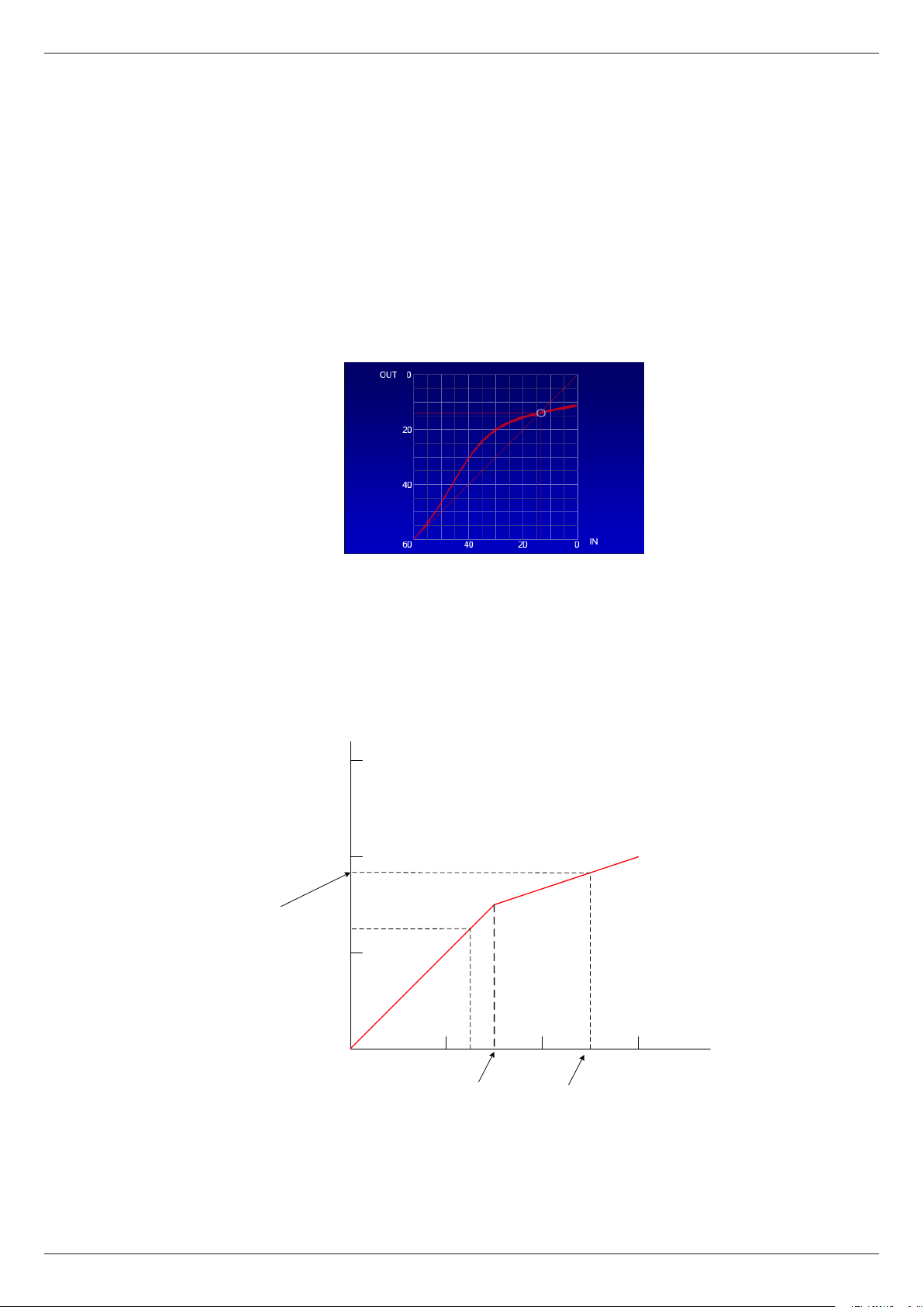
56
Release – this works in a similar manner to the Noise Gate’s Release
parameter; after the signal level drops below the compressor threshold,
the gain reduction applied as a result of the compressor action is gradually
reduced. Setting the Release parameter to suit the signal being treated will
generally minimise the effect of “pumping” that compression can produce.
Transfer Characteristic and meters
The Dynamics detail page also provides separate input and output metering for
the gate, compressor and limiter (in the case of the Groups and Aux Sends), which
allows a quick evaluation to be made of the effects of the dynamics processing. A
Gain Reduction meter for the compressor is also implemented on-screen.
The transfer characteristic displays the relationship between input and output
levels graphically, and shows the effects of the compressor’s Threshold, Ratio
and Level controls. The horizontal (x-) axis represents input signal levels, and the
vertical (y-) axis output levels. The output signal level for any input signal level
can be found by tracing a line vertically from the x-axis at the point representing
the input signal level to the transfer curve, then reading across horizontally to the
y-axis.
0
-20
Output level = -23 dB
-40
-60
A B
-40
THRESHOLD
-20
Input level = -10 dB
0
With no compressor action (i.e., with the compressor by-passed, or with Ratio set
to 1:1), the transfer characteristic is a straight line at 45° to both axes. The line
becomes “kinked” when compression is applied. In the example above, the input
signal at A is at -35 dB, and hence below the threshold of -30 dB; no compression
Revision 1 2012-13 CDC FOUR
Page 57

is applied, and the output level is also -35 dB. The signal level at B is -10 dB,
which is above the threshold. This results in the output level being reduced by 13
dB to -23 dB. Real world signals, of course, have a dynamic range which includes
elements both above and below the threshold, so the effect of compression is
only for the louder elements to be reduced in level, which will reduce the overall
volume. This reduction can be compensated for with the Level control.
As with the Channel Overview page, the dynamics processing of each channel
may be viewed and compared by pressing each channel’s SEL button in turn.
57
Revision 1 2012-13CDC FOUR
Page 58

58
FX processing
The FX button opens the FX Settings page; the two internal DSP effects processors
are controlled from here. The two processors each have their own (identical)
control page; Softkeys 4 and 5 select that for FX1 and FX2 respectively. The
controls on these pages have no hardware equivalents, and are selected and are
adjusted by using the cursor keys and the ADJUST control.
Each FX processor comprises three separate FX “modules”: Reverb, Delay and
Modulation.
The default input signal to each FX module is the signal being sent to the FX1 (or
FX2) buss. This is indicated by the Input buttons, which may alternatively be set
to Off to disable the effect of that module, or to the other FX buss, or to any of
the eight Aux busses. The three modules are effectively “in parallel”, and may be
used individually, or in combination. Alternatively, the modules may be connected
“in series” using the Send controls in the Modulation and Delay modules. Thus,
the Modulation module may feed either the Delay or Reverb modules, with the
Reverb or Delay module remaining free to be used with another source; or all
three modules may be cascaded.
The outputs of the two FX processors can be added to the Stereo Master mix, or
to any of the four Groups, by using faders 13 and 14 in the Outputs layer. See
“FX sends and returns” on page 49 for full information on the audio path of the
FX channels.
Module 1 - Modulation
The Modulation module may be used to generate a range of time-variant “phasing”
effects of various kinds. 8 standard modulation presets are provided, which may
be selected with the Preset control. These are:
Chorus Slow
Chorus Fast
Flanger Slow
Flanger Fast
Celeste Slow
Celeste Fast
Rotor Slow
Revision 1 2012-13 CDC FOUR
Page 59

Rotor Fast
Once a Preset has been selected, the effect may be modied as required by
adjusting its various parameters:
Filtering – the Modulation module is provided with variable-frequency hi-pass
and lo-pass shelving lters which may be used to select the band of frequencies
that the Modulation will apply to. The lo-pass lter turnover frequency is adjusted
with the LS Frequency control, which has a range of 20 to 200 Hz, with a default
value of 100 Hz. The LS Gain control has a range of ±18 dB. Similarly, the HS
controls affect the higher frequencies; HS Frequency has a range of 1.5 to 15
kHz with a default value of 6.3 kHz; the HS Gain range is also ±18 dB.
Modulation – the Modulation rate and Intensity controls adjust the frequency
and amount of modulation respectively. The controls’ ranges are in arbitrary units,
from 50 to 200, with default values of 100.
Sends – the Send Reverb and Send Delay controls send the Modulation
module’s output to the Reverb and Delay modules respectively.
Modulation output – the output level to the FX return channel from the Modulation
module is adjusted with the Modul Out control. A Modul Pan control is also
provided.
59
Module 2 - Delay
The Delay module is an audio delay line congured specically for musical use.
The module can generate single or multiple echoes at time intervals which may
specied in terms of BPM, and can be set by the user using a Tap Tempo feature.
Six delay presets are provided, which may selected with the Preset control:
One Echo 1/4
Two Echo 1/8
Three Echo 1/16
Three Echo 1/16 Delayed
Four Echo 1/16
One Echo 1/4 with 4 Reect.
Once a Preset has been selected, the delay effect may be modied as required
by adjusting its various parameters.
Filtering – the Delay module is provided with the same variable-frequency hi-pass
and lo-pass shelving lters as the Modulation module. The LS Frequency, LS
Gain, HS Frequency and HS Gain controls have the same functions, parameter
ranges and default values.
Delay time - may be set as a BPM value, using the Tempo control (range 40
to 240 BPM) in conjunction with the Factor control. The Factor control has a
range of 0 to 13 (arbitrary units), with a default value of 8. With Factor set to 8,
the Delay Time (displayed below the Factor control) is based on one repeat per
beat; i.e., with a BPM of 120 and Factor set to 8, the delay time will be 500 ms.
Setting Factor to 9 doubles the delay time to 1 s; setting it to 7 halves it to 250 ms.
The maximum delay available from the Delay Module is 2 s.
Revision 1 2012-13CDC FOUR
Page 60

60
The table below summarises the relationship between Factor and Delay Time:
FACTOR RATIO TO BPM
1 1/24
2 1/16
3 1/12
4 1/8
5 1/6
6 1/4
7 1/2
8 Equivalent to BPM
9 x 2
10 x 3
11 x 4
12 x 5
13 x 6
Alternatively, a delay time may be set directly by adjusting the BPM and Factor
controls while observing the Delay Time display. Factor will operate as a “coarse”
delay time control, while BPM will act as a “ne” control.
Additionally, the output of the delay line may be fed back to its input with the
Feedback control to create multiple echoes with decaying amplitude.
Tap Tempo – Softkey 1 may be used to input a BPM value by tapping the button;
a minimum of three taps is required. The tempo of the taps will then dene the
delay time.
Sends – the Send Reverb control sends the Delay module’s output to the Reverb
module.
Module output – the output level of the Delay module is adjusted with the Delay
Out control. A Delay Pan control is also provided.
Module 3 – Reverb
The Reverb Module offers six basic room/plate simulations, which may be
selected with the Preset control:
Hall Bright – a large space
Hall Warm – as Hall Bright, but with less hard surfaces
Room Bright – a small space
Room Warm – as Room Bright, but with less hard surfaces
Plate Bright – simulation of a traditional echo plate
Plate Warm – as Plate Bright, but with reduced HF reections
Once a Preset has been selected, the reverberation may be modied as required
by adjusting its various parameters.
Filtering – the Reverb module is provided with the same variable-frequency
hi-pass and lo-pass shelving lters as the Modulation and Delay modules. The
Revision 1 2012-13 CDC FOUR
Page 61

LS Frequency, LS Gain, HS Frequency and HS Gain controls have the same
functions, parameter ranges and default values.
Reverb – the Reverb Time parameter sets the basic “size” of the space being
simulated, i.e., its RT60 value. The range of available reverb times is preset-
dependent:
PRESET MIN. MAX DEFAULT
61
Hall Bright
0.8 s 12.0 s 1.6 s
Hall Warm
Room Bright
0.4 s 8.0 s 0.8 s
Room Warm
Plate Bright
0.4 s 6.0 s 0.6 s
Plate Warm
Module output – the output level of the Reverb module is adjusted with the
Reverb Out control.
Revision 1 2012-13CDC FOUR
Page 62
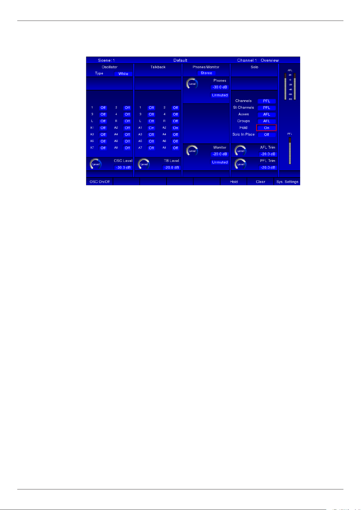
62
System
The System page provides controls for the CDC FOUR’s oscillator, talkback
routing, monitor control functions and Solo system control. The page is divided
in four Modules, plus an area on the right for PFL and AFL metering. Most of the
controls on these pages have no hardware equivalents, and are selected and
adjusted by using the cursor keys and the ADJUST control.
Oscillator
The CDC FOUR’s line-up oscillator can generate a sine wave, white noise or pink
noise for system test or alignment, or for room equalisation purposes.
The oscillator is enabled by pressing Softkey 1 (OSC On/Off). The Type button
selects the oscillator output signal – Sine, White (Noise) or Pink (Noise). When
Sine is selected, a Freq control becomes available; in this mode, the oscillator
has a range from 10 Hz to 10 kHz. The Oscillator output level is adjusted with the
OSC Level control.
The routing buttons allow the oscillator signal to be routed to any combination of:
L & R – Stereo master buss
1 to 4 – Groups 1 to 4
A1 to A8 – Aux busses 1 to 8
Revision 1 2012-13 CDC FOUR
Page 63

63
U1
U2
U3
U4
Talkback
A dynamic microphone or talkback headset mic may be connected to the
TALKBACK connector on the rear panel. Talkback mic level is adjusted with
the TALKBACK rotary control at the top right of the mixer control surface, or the
corresponding virtual TB Level control in the Talkback module.
The routing buttons allow talkback to be routed to any combination of:
L & R – Stereo master buss
1 to 4 – Groups 1 to 4
A1 to A8 – Aux busses 1 to 8
Thus the engineer may speak to the FOH output, individual monitor speakers
(when the Aux busses are being used for artist foldback) or to the Group outputs,
which may be in use to feed different parts of the stage or auditorium, or a recorder.
The microphone is made active when the TALK button is pressed. The TALK
TALK
button is momentary, and thus must be held down while speaking.
ADJUST
+
TALK
BACK
60 0
PHONES
+
M
MONITOR
+
SUM M
-
Phones/Monitor
A detailed block diagram of the Phones/Monitor section may be found in the
Appendix on page 79.
-
The CDC FOUR’s monitoring system allows for the connection of either (or both)
headphones or a stereo power amplier and a pair of monitor loudspeakers. The
monitor system will carry the Stereo Master output signal, unless a SOLO button
-
is pressed somewhere on the mixer, in which case either a mono PFL or a stereo
AFL signal from the channel in question will be heard instead.
A standard 3-pole ¼” headphones jack socket is provided at the front of the mixer,
under the fader block. The rear panel provides three ¼” jacks for connection of an
external stereo (MON L and MON R) or a mono (MON M) power amplier (useful
for an engineer’s local wedge monitor). The front panel headphone socket and
the rear panel monitor outputs have their own level controls and may be used
simultaneously.
The headphone volume may be adjusted with the rotary PHONES control, or its
virtual equivalent, Phones Level. The headphone output may be muted with the
M button below the level control or on-screen.
The separate monitor output level is adjusted with the rotary MONITOR control,
or its virtual equivalent, Monitor Level. The monitor output may be muted with
the M button below the level control or on-screen.
The stereo monitor outputs may be summed to mono with either the SUM button,
or the Mono on-screen button.
SOLO LOGIC
HOLD SIP
CLEAR
Solo control
The CDC FOUR’s solo system is entirely conventional in operation and follows
the long-established practices implemented in CADAC analogue consoles. The
solo system allows an engineer to monitor any of the various inputs or outputs
(individually or in combination) on headphones or loudspeakers, without otherwise
altering any signal ows through the mixer.
Any channel in the currently selected Layer may be routed to the solo system
by pressing the SOLO button above its fader. Alternatively, the channel currently
Revision 1 2012-13CDC FOUR
Page 64

64
assigned to the CAM may be soloed with the CAM’s SOLO button, or the on-
screen Solo button using screen navigation in the normal manner.
The action of the SOLO buttons in combination may be controlled with the HOLD
button. When HOLD is not selected, the SOLO buttons are interlocking, and
pressing a second SOLO button while one is already active will deselect the rst;
only one channel may be soloed at a time.
With HOLD selected, the SOLO buttons become latching and remain selected
when pressed until a second press deselects it. Additional channels may be
soloed simultaneously, allowing the monitoring of multiple channels. The CLEAR
button may be used to deselect all SOLO buttons currently active with a single
button press.
Softkey 6 (Hold) is the on-screen equivalent of the hardware HOLD button.
Softkey 7 (Clear) is the on-screen equivalent of the hardware CLEAR button.
PFL and AFL
The on-screen Solo module allows the Solo system to be congured to suit
individual requirements. The SOLO buttons in mic/line channels, stereo channels,
Aux channels and Groups may be individually selected to operate in PFL (mono)
or AFL (stereo) mode, with the on-screen Channels, St Channels, Auxes and
Groups buttons respectively.
Channels soloed in PFL mode will route the pre-fade signal to the solo system,
thus the fader position and mute button will not affect the signal being monitored.
The PFL signal is, however, post all DSP processing, so the effect of EQ, dynamics
and delay can be checked. If stereo channels or the FX channels are solo’d in
PFL mode, a mono sum of the left and right legs is heard.
Channels soloed in AFL mode will route the post-fade, post-panpot signal to the
solo system; thus stereo channels will be heard correctly in stereo, and a mono
signal will be heard in its correct position in the stereo image. Fader and mute will
affect the solo signal.
When a Group is soloed in AFL mode, the post-fade, post-panpot signal is routed
to the monitor mix.
When an Aux. send is solo’d in either mode, the signal is always mono, but prefade in the case of PFL, and post-fade for AFL.
Revision 1 2012-13 CDC FOUR
Page 65

65
TALK
BACK
60 0
PHONES
+
M
MONITOR
+
SUM M
Solo system metering and levels
LISTEN
LEVEL
AFL/PFL
MIX
0dB
-
Stereo Left
AFL/PFL
Stereo Right
MIX
0dB
-
The solo signals are fed into the mixer’s monitoring system, where they are routed
to the rear panel Monitor Outputs (both as stereo and as a mono sum), and the
stereo headphone socket under the front armrest.
The front headphones output has its own volume control (PHONES) and mute
(M) button.
LEVEL
LEVEL
LISTEN
LEVEL
LEVEL
LEVEL
DAC
DAC
DAC
DAC
Buffer
10dB
Buffer
10dB
Bal OP
0dB
Bal OP
0dB
MIX
0dB
LEVEL
Bal OP
0dB
MUTE
FRONT
PANEL
HEADPHONE
MUTE
DIM
14dB
MUTE
DIM
14dB
MUTE
MONITOR
OUTPUT
LEFT
MONITOR
OUTPUT
RIGHT
MONITOR
OUTPUT
MONO
SOLO LOGIC
HOLD SIP
CLEAR
Signals solo’d in PFL mode will generally be at a higher level than those solo’d in
AFL mode, so separate trim adjustments are also provided for the AFL and PFL
systems. These are on-screen controls, and can be found in the Solo module of
the SYSTEM screen page.
SIP mode
The PFL and AFL modes described above are only monitoring modes, and do
not alter any other signal routings through the mixer. They are non-destructive,
and can be used safely during performance or recording without endangering any
other outputs from the mixer.
A further solo mode, SIP (Solo-in-Place) is available which is destructive. This
mode is also often referred to as ‘Check Solo’. SIP mode is enabled by pressing
the SIP button.
In SIP mode, soloing any input channel mutes every other input channel; thus
the soloed channel is the only one left feeding the master output (or Group, if
applicable). Thus it is ‘truly’ soloed, by virtue of all other signals being removed.
This mode is useful when setting up for performance or recording, but should
clearly be used with great caution otherwise!
Solo In Place mode may be selected On or Off by pressing and holding the SIP
button for at least 3 seconds, or clicking or its on-screen equivalent. When Solo
In Place is On, pressing a SOLO button anywhere on the mixer mutes all other
channels.
Mono PFL and stereo AFL meters are also provided on the SYSTEM page.
Revision 1 2012-13CDC FOUR
Page 66

66
System Settings
Pressing Softkey 8 from the SYSTEM page opens an “engineering” page, which
provides information about the rmware version and Ethernet IP address, and
access to further engineering pages via the following softkeys:
Softkey 1 (Fact. Reset) reinitialises the CDC FOUR’s control system. All audio
will be muted during reboot, and all mixer settings will be lost. All parameters will
be reset to their default values.
Softkey 6 (Maintenance) opens the CDC 4 maintenance page allowing mixer
and/or scene settings to be saved and recalled from an external USB memory
device, and other engineering functions. See page 80 for further details.
Softkey 8 (System) returns to the System page.
Revision 1 2012-13 CDC FOUR
Page 67

Scene Control
The CDC FOUR incorporates a Scene Memory system. This is a “snapshot”
automation system, and allows every audio-related parameter* on the mixer to
be saved as a Scene, named, and subsequently recalled. A Scene may typically
include channels being muted and unmuted, levels being changed, and FX sends
being enabled, but may extend to any mixer function, such as EQ and dynamics
adjustments, routing, FX parameter changes, etc. Up to 999 Scenes may be
saved in this way.
The Scene Memory feature is extremely useful in theatre production work, as
entire sound congurations may be set up and optimised in rehearsal, and
then saved. During performance, the engineer merely has to step through the
consecutive scenes at the appropriate cue to reset the entire mixer to the correct
settings.
* An important exception is the position of the Stereo Master fader; being non-automated, this
remains manual at all times.
67
Current Scene
An important aspect of the Scene Memory system is that the current status of
the mixer at all times – i.e., the settings of all mixer controls - is constantly being
written into a single memory location, referred to as the Current Scene. This is
a non-volatile memory, and during the mixer’s boot procedure, the contents of
the Current Scene are recalled. This means that if the mixer suffers a temporary
power failure, its last-known state will be automatically reinstated in all respects
when power returns.
When a Scene is saved, the contents of Current Scene is copied into the selected
Scene Memory.
Pressing the SCENE button adjacent to the screen opens the Scene page:
The scenes which have been saved in the mixer’s internal Scene Memory are
displayed in tabular form.
Revision 1 2012-13CDC FOUR
Page 68
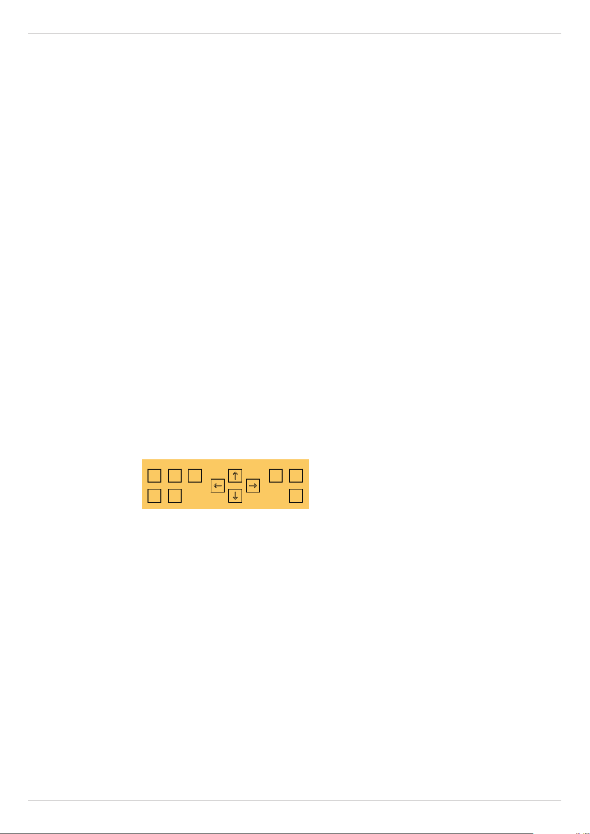
68
Default Scene
Initially, the only scene in the list is Default. This scene is constant, and cannot be
deleted, altered or over-written. Recalling this scene will return the entire mixer
to a factory default state, with all channel parameters effectively “reset”. This
function is useful when resetting the mixer for a new project, but should be used
with caution otherwise!
Insert a Scene
New Scenes may be added to the Scene list by pressing Softkey 1 (Insert). This
copies the contents of the Current Scene memory (see above) into a new Scene
in the list. This Scene will be named NEW_SCENE, but may be subsequently
renamed (see below).
Renaming Scenes:
To rename a Scene, move the red box to the Scene name in the second column
(Name) – e.g., NEW_SCENE. Press ENTER, and a pop-up list will appear,
enabling the Scene name to be changed. Press Softkey 5 (Reset Name) to clear
the eld. Use the ADJUST knob to scroll to the rst character of the new name
from the pop-up list and then press the RIGHT cursor key and repeat. Continue
this process until all the characters have been entered as required. Note that
both upper and lower case letters, numbers and other characters are available; a
space character can be found after the upper case letters.
Overwriting Scenes:
To save the mixer’s current settings into an existing Scene, select the required
Scene by moving the red box in the displayed list, and press either the SAVE key,
or Softkey 4 (Save). This will over-write the existing Scene.
Recalling Scenes:
CONTROL
DEL RCL SVE COPY PASTE
PN
ENTER
To recall a previously saved scene, use the ADJUST control to move the red box
to the required scene in the Scene List (any column), and press either RCL or
Softkey 3 (Recall). This will replace the mixer’s current settings with those from
the memory. Any channel level differences in the currently-selected layer will be
implemented by movements of the motorised faders.
The sequence of scenes making up the Scene list may be stepped through one
at a time by pressing the green N button (Next). At any time, the previous scene
in the list may be recalled by pressing the red P button (Previous).
Deleting scenes
A Scene may be deleted from the Scene list by selecting, and pressing either the
DEL button or Softkey 2 (Delete).
Shortcut Scene Recall
User keys U1 to U4 may be assigned as shortcut triggers, which will recall any
Scene in the list, removing the necessity to scroll through the list. To assign a
Scene to one of the User keys, move the red box to Column 3 (Action) for the
required Scene, and press ENTER. Scroll to one of the four User keys in the
Revision 1 2012-13 CDC FOUR
Page 69

displayed pop-up list (USR 1 to USR 4), and press ENTER again.
If a User Key previously had a Scene assigned to it, that assignment will be
cancelled, and the key will now recall the new Scene.
MIDI commands
Column 4 in the list – Event – is not currently implemented.
69
Revision 1 2012-13CDC FOUR
Page 70

70
GRAPHIC EQ
1-16
BANDS
17-32
6/12
IN
Other mixer functions
Graphic Equaliser
The CDC FOUR is equipped with a stereo 32-band graphic equaliser in the main
output signal path. It is pre-fade and pre-dynamics, but post the main output
channel’s standard parametric EQ.
The equaliser settings are controlled by the channel faders, and effectively
constitute a sixth control Layer. As there are only 16 faders, the audio frequency
band is split into two, and the faders used to control either the sixteen frequencies
below 1 kHz, or above I kHz, respectively.
A graphical representation of the equaliser may be obtained by pressing Softkey
6 (GEQ) from the Master Sel screen page. Pressing Softkey 8 (Master Sel) from
this page will return to the previous page.
Control of the graphic equaliser is assigned to the faders by pressing the IN
button and one of the 1-16 or 17-32 buttons. If the equaliser has not already been
placed in circuit and adjusted, the 16 motorised faders will jump to their mid-
10
+6 (or 12) dB
+6 (or 12dB)
+
0
position; otherwise, they will assume positions corresponding to the EQ curve
previously set. Note that Fader 16 has no function when 17-32 is selected.
5
0
Pressing any Layer Select button will revert the faders to control of another layer,
but the graphic equaliser’s settings will remain applied to the main output.
5
The equaliser can cut or boost bands of frequencies (centred on the ISO standard
10
frequencies) by either 6 dB or 12 dB, according to the setting of the 6/12 button.
20
When the button is lit, 12 dB of cut/boost is selected.
30
40
50
60
-6 (or 12) dB
Revision 1 2012-13 CDC FOUR
-
∞
ST 1
GP 1
Page 71
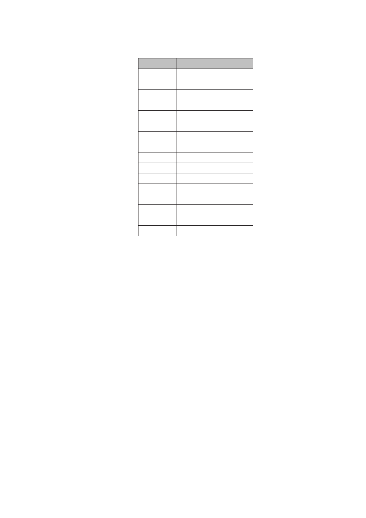
The centre frequency of the band which each fader controls is as follows:
Fader 1-16 17-32
1 20 Hz 800 Hz
2 25 Hz 1 kHz
3 31 Hz 1.25 kHz
4 40 Hz 1.6 kHz
5 50 Hz 2 kHz
6 63 Hz 2.5 kHz
7 80 Hz 3.15 kHz
8 100 Hz 4 kHz
9 125 Hz 5 kHz
10 160 Hz 6.3 kHz
11 200 Hz 8 kHz
12 250 Hz 10 kHz
71
13 315 Hz 12.5 kHz
14 400 Hz 16 kHz
15 500 Hz 20 kHz
16 630 Hz (not used)
Note that pressing Softkey 5 (Flat) from the Graphic Equalizer page will remove
the EQ curve and atten the frequency response.
USB port
The Type ‘A’ USB port on the top panel is for the connection of a USB memory
device or USB QWERTY keyboard.
A memory device connected here enable console congurations and scene data
to be backed-up and restored. See “Maintenance page” on page 80.
Ethernet port
Used specically for updating the CDC FOUR’s operating system when software
updates are available. See “Maintenance page” on page 80.
MIDI
The CDC FOUR is equipped with a standard MIDI interface, consisting of three
rear panel 5-pin DIN sockets: MIDI, IN, OUT and THRU.
The MIDI interface will be implemented in a future software release.
Revision 1 2012-13CDC FOUR
Page 72

72
User buttons (U1 – U4)
ADJUST
+
TALK
U1
U2
U3
U4
-
Four programmable soft keys are provided for the operator’s use. These are U1
to U4, to the right of the TFT screen.
The User buttons can be programmed from the Scene page. They allow immediate
Scene recall without the necessity of using the Scene page. See “Shortcut Scene
Recall” on page 68.
Revision 1 2012-13 CDC FOUR
Page 73

Technical Specication
Channels 32 (16 mono 8 stereo)
Auxiliaries 8 mono (Switchable pre/post fader) + 2 FX (Switchable pre/post fader)
Sub groups 4 mono, route and pan to Main LR
Input impedance 1k2 ohm mic input on XLR of combi connector
Equivalent Input Noise Better than 128 dB
Input impedance 10k ohm electronically balanced on jack of combi connector
Nominal input level -21 dBFS (0 dBu)
Max. input level 0 dBFS (+21 dBu) balanced -11 dBFS unbalanced (+ 10 dBu)
Max. output level +21 dBu (0 dBFS)
CMRR -70 dB (50 Hz – 10 kHz)
Signal to noise -100 dB
Dynamic range 114 dB A weighted
73
THD -100 dB
Frequency response 20 Hz to 35 kHz ± 0.5 dB
Crosstalk Better than -80 dB at 10 kHz
Phase response ≤10o @ 20 Hz
ADC 24 bit, 96 kHz
DAC 24 bit, 96 kHz
Internal 40 bit oating point
Revision 1 2012-13CDC FOUR
Page 74

74
Appendix
Input Channel Block Diagram
0dB
OUTPUT
Bal OP
DIRECT
6-24dB/Oct
See design brief
for specs
Input channel - INPUT 1 shown
(FEMALE
XLR)
MIC
1
3
2
48v ON
HPF IN
IN
DYNAMICS
48v
GAIN
Buffer
0dB
Buffer
0dB
20dB
PAD
10-60dB
MIC
ADC
14-400Hz
HPF
Limiter
DYNAMICS
Delay
Gate
Compressor
20-200Hz
SHELF SHELF
EQ
60-600Hz 400-4kHz
1k5-15kHz
EQ IN
Buffer
0dB
10dB
Buffer
PAN IN
MUTE
PAN
Buffer
Buffer
4.5dB
AUX PRE
AUX PRE
AUX PRE
LEVEL
LEVEL
LEVEL
FX 2
AUX 8
FX 1
AUX PRE
LEVEL
GROUP 4
AUX 1
GROUP 2
GROUP 3
GROUP 1
4.5dB
STEREO
FADER
SIG
AS PER J-TYPE CONSOLE
PFL & AFL
DYNAMICS
POST EQ
METER POST
12dB
18dB
0dB
6dB
3dB
3dB
24dB
PFL/AFL HOLD/CLEAR SYSTEM
METER
12dB
OL
6dB
PFL
AFL L
AFL R
GROUP 1
GROUP 2
GROUP 3
GROUP 4
FX 1
FX 2
AUX 1
AUX 2
AUX 3
AUX 4
AUX 5
AUX 6
AUX 7
AUX 8
STEREO L
STEREO R
Revision 1 2012-13 CDC FOUR
Page 75

Stereo Inputs block diagram
75
Stereo Input Channel
6-24dB/Oct
See design brief
for specs
SHELF SHELF
RIGHT
INPUT
20dB
PAD
Bal IP
0dB
ADC
14-400Hz
Limiter
Delay
Gate
Compressor
20-200Hz
60-600Hz 400-4kHz
1k5-15kHz
HPF
DYNAMICS
EQ
See design brief
for specs
6-24dB/Oct
SHELF SHELF
INPUT
LEFT
20dB
PAD
Bal IP
0dB
ADC
14-400Hz
HPF
HPF IN
Limiter
DYNAMICS
Delay
Gate
Compressor
DYNAMICS
IN
DYNAMICS
20-200Hz
60-600Hz 400-4kHz
1k5-15kHz
EQ
POST EQ
EQ IN
Buffer
0dB
10dB
Buffer
MIX
0dB
MUTE
AUX PRE
AUX PRE
AUX PRE
AUX PRE
LEVEL
LEVEL
LEVEL
LEVEL
GROUP 2
AUX 8
FX 2
FX 1
AUX 1
GROUP 1
PAN IN
GROUP 2
GROUP 1
STEREO
Buffer
0dB
10dB
Buffer
MIX
0dB
METER POST
FADER
BAL
Buffer
Buffer
4.5dB
4.5dB
PFL/AFL HOLD/CLEAR SYSTEM
AS PER J-TYPE CONSOLE
PFL & AFL
METER
12dB
12dB
18dB
OL
6dB
0dB
6dB
3dB
3dB
SIG
24dB
METER
12dB
12dB
18dB
OL
6dB
0dB
6dB
3dB
3dB
SIG
24dB
PFL
AFL L
AFL R
GROUP 1
GROUP 2
GROUP 3
GROUP 4
FX 1
FX 2
AUX 1
AUX 2
AUX 3
AUX 4
AUX 5
AUX 6
AUX 7
AUX 8
STEREO L
STEREO R
Revision 1 2012-13CDC FOUR
Page 76

76
Groups block diagram
PFL
AFL L
AFL R
GROUP 1
GROUP 2
GROUP 3
GROUP 4
FX 1
FX 2
AUX 1
AUX 2
AUX 3
AUX 4
AUX 5
AUX 6
AUX 7
AUX 8
STEREO L
STEREO R
MIX
0dB
20-200Hz
SHELF SHELF
EQ
60-600Hz 400-4kHz
1k5-15kHz
EQ IN
DYNAMICS PRE EQ
Limiter
DYNAMICS
Delay
Gate
Compressor
See design brief
for specs
DYNAMICS
IN
MUTE
METER
12dB
12dB
18dB
OL
6dB
0dB
6dB
3dB
3dB
SIG
24dB
PFL & AFL
10dB
Buffer
PAN
Buffer
Buffer
4.5dB
4.5dB
STEREO
DAC
Bal OP
0dB
MUTE
Group Output
GROUP 1
OUTPUT
Revision 1 2012-13 CDC FOUR
Page 77

Aux outputs block diagram
77
PFL
AFL L
AFL R
GROUP 1
GROUP 2
GROUP 3
GROUP 4
FX 1
FX 2
AUX 1
AUX 2
AUX 3
AUX 4
AUX 5
AUX 6
AUX 7
AUX 8
STEREO L
STEREO R
MIX
0dB
SHELF SHELF
See design brief
for specs
PFL & AFL
20-200Hz
EQ
60-600Hz 400-4kHz
1k5-15kHz
EQ IN
Limiter
DYNAMICS
Delay
Gate
Compressor
DYNAMICS
IN
MUTE
METER
12dB
12dB
18dB
OL
6dB
0dB
6dB
3dB
3dB
SIG
24dB
10dB
Buffer
DAC
Bal OP
0dB
MUTE
OUTPUT
AUX 1
Aux Output
Revision 1 2012-13CDC FOUR
Page 78

78
Stereo master block diagram
PFL
AFL L
AFL R
GROUP 1
GROUP 2
GROUP 3
GROUP 4
FX 1
FX 2
AUX 1
AUX 2
AUX 3
AUX 4
AUX 5
AUX 6
AUX 7
AUX 8
STEREO L
STEREO R
SHELF SHELF
See design brief
for specs
PFL & AFL
SHELF SHELF
See design brief
for specs
MIX
0dB
20-200Hz
EQ
60-600Hz 400-4kHz
1k5-15kHz
EQ IN
DYNAMICS PRE EQ
Limiter
DYNAMICS
Delay
Gate
Compressor
DYNAMICS
IN
METER
12dB
12dB
18dB
OL
6dB
0dB
6dB
3dB
3dB
SIG
24dB
METER
12dB
12dB
18dB
OL
6dB
0dB
6dB
3dB
3dB
SIG
24dB
10dB
Buffer
MIX
0dB
20-200Hz
EQ
60-600Hz 400-4kHz
1k5-15kHz
EQ IN
Limiter
DYNAMICS
Delay
Gate
Compressor
DYNAMICS
IN
10dB
Buffer
DAC
MIX
0dB
LEVEL
Bal OP
0dB
MUTE
1
3
2
MASTER
OUTPUT
MONO
Bal OP
0dB
14dB
DIM
MUTE
1
3
2
MASTER
OUTPUT
RIGHT
DAC
Bal OP
0dB
14dB
DIM
MUTE
1
3
2
MASTER
OUTPUT
LEFT
Bal OP
0dB
OUTPUT
RIGHT
TAPE
Bal OP
0dB
MUTE
MUTE
Stereo Output
OUTPUT
RIGHT
TAPE
Revision 1 2012-13 CDC FOUR
Page 79

Phones/Monitor block diagram
PFL
AFL L
AFL R
GROUP 1
GROUP 2
GROUP 3
GROUP 4
FX 1
FX 2
AUX 1
AUX 2
AUX 3
AUX 4
AUX 5
AUX 6
AUX 7
AUX 8
STEREO L
STEREO R
79
FROM STEREO MASTER
MIX
MIX
0dB
0dB
SIG
24dB
SIG
24dB
LEVEL
LEVEL
TRIML
AFL
MIX
MIX
0dB
0dB
LEFT
RIGHT
2 Track Tape Return
2 Track Tape Return
STEREO
LEVEL
DAC
STEREO
LISTEN
LEVEL
LEVEL
DAC
STEREO
MIX
MIX
0dB
0dB
LISTEN
LEVEL
LEVEL
LEVEL
DAC
DAC
MIX
0dB
METER
12dB
12dB
18dB
OL
6dB
0dB
6dB
3dB
3dB
METER
12dB
12dB
18dB
OL
6dB
0dB
6dB
3dB
3dB
METER
12dB
12dB
18dB
OL
6dB
0dB
6dB
3dB
3dB
SIG
24dB
LEVEL
TRIM
PFL
10dB
10dB
Buffer
MIX
0dB
LEVEL
Bal OP
0dB
MONITOR
OUTPUT
MONO
Bal OP
0dB
14dB
DIM
MUTE
MONITOR
OUTPUT
RIGHT
Bal OP
0dB
14dB
DIM
MUTE
LEFT
MONITOR
OUTPUT
Buffer
MUTE
MUTE
MONITOR
OUTPUT
MONO
Revision 1 2012-13CDC FOUR
Page 80

80
Maintenance page
CENTRAL CONTROL MODULE
USB
METERS
SCENE
FX
ROUTE
SYSTEM
CHN
NOTE: Selecting the Maintenance page from the System Settings page stops
the CDC FOUR’s main operating program and starts a separate software routine.
Audio is muted in Maintenance mode, so this page should not be opened during
performance. Loading the maintenance page takes approx. 20 seconds.
The following options are available from the Maintenance page via the Softkeys:
Softkey 1 (Full Backup): This permits all settings, parameters and rmware in
the CDC FOUR to be saved to an external memory device connected to the
USB port in the Central Control Module. It effectively creates a full “image” of the
console for security purposes.
A full backup creates a zip le cdc4-update.zip in the root folder of the
memory device. The size of the le is approx. 2MB.
Softkey 2 (Scene Backup): This allows the current Scene List to be backed up
to external memory. A zip le cdc4-scene.zip is created in the root folder of
the memory device. Note – any subsequent Backup will overwrite the previously-
saved le, as the lename is unique.
Softkey 3 (Full Restore): Selecting this option will allow all the CDC FOUR’s
settings to be restored in full to a previously-saved state. The Full Restore
procedure looks for a backup zip le on the memory device, and will automatically
restore all settings without further operator action.
Softkey 4 (Scene Restore): This option loads a previously-saved Scene List into
the CDC FOUR, thus allowing the “running order” of a show to be restored.
Softkey 5 (Net Update): Select this option to perform a remote software update.
The CDC FOUR will automatically download the latest software directly from
Cadac’s support server.
WARNING: Performing a Net Update will delete ALL console settings, including
all stored Scenes. Before proceeding with the update procedure it is strongly
recommended that either a Full Backup or Scene Backup is performed.
Proceed as follows:
Revision 1 2012-13 CDC FOUR
Page 81

Ensure that an Ethernet cable with Internet connection is plugged into the CDC
FOUR’s rear panel RJ45 socket.
Reboot by power-cycling the mixer, then return to the Maintenance page and
select Net Update.
The CDC FOUR will automatically download and install the current version of
software.
NOTE: The CDC FOUR will always download and install the latest version of
software irrespective of whether it is already installed in the console or not.
Upon completion, the CDC FOUR will display the following message, “Software
successfully updated to the latest version!”
To re-boot the CDC FOUR it is necessary to power-cycle the console twice. After
the rst power-cycle wait until all the LEDs on the console are lit, then perform the
second power-cycle. The console will then boot with the latest version of software
installed.
81
To check which version of software the console is running, press the System
button and then the System Settings softkey (Sys.Settings).
If console scenes were backed-up prior to updating the software then restore
these into the CDC FOUR by using the Scene Restore function above.
NOTE: It is not possible to return to the CDC FOUR’s normal operating system
from the Maintenance page. To exit this page, please re-boot the console by
power-cycling.
Revision 1 2012-13CDC FOUR
Page 82

82
Connecting the CDC FOUR to unbalanced sources and desti-
nations
All inputs and outputs on the CDC FOUR are electronically balanced. Balanced
interconnections to external equipment are recommended, as they will minimise
noise pickup, hum problems, and generally use superior quality connectors.
Most current professional audio equipment is equipped with balanced inputs and
outputs, but it may occasionally be necessary to interface the CDC FOUR with
equipment having unbalanced inputs and/or outputs. Cadac’s recommended
method of connecting balanced and unbalanced terminations is shown below:
Revision 1 2012-13 CDC FOUR
Page 83

83
Revision 1 2012-13CDC FOUR
 Loading...