

Page 1

#
&g8;2'
Audio Mixing Console
-056#..#6+10#n#95'4#1#07#.
Page 2

CADAC Electronics
One New Street
Luton
Bedfordshire
LU1 5DX
England
Tel + 44 (0) 1582 404 202
Fax +44 (0) 1582 412 799
email: info@cadac-sound.com
While every effort has been taken to ensure the accuracy of the contents in this manual, CADAC Audio Mixing Consoles are subject to continu ous development, hence the inform ation in this manual may not reflect the latest product updates.
© Copyright CADAC Electronics plc. 2005.
Page 3

Table of Contents iii
7DEOH#RI#&RQWHQWV
6(&7,21 3$*(
*HQHUDO#3UHFDXWLRQV 1111111111111111111111111111111111111111111111 #LLL
,QWURGXFWLRQ11111111111111111111111111111111111111111111111111111111111111#Y
4 &RQQHFWLQJ#WKH#PL[HU#V\VWHPV1111111111111111111111111111 #404
1.1 Console modularity ....................................................................... 1-1
1.2 Frame rear connections................................................................1-1
1.3 Connect Power supply systems.................................................... 1-2
1.4 Connecting the console frames .................................................. 1-11
1.5 Connect Console Automation System ........................................ 1-14
1.6 Connect main frame facilities from modules to frame.................1-19
1.7 Switching ON .. .... ............... .... .... .... ............... .... .... .... ............... ... 1-20
5 &HQWUDO#&RQWURO#0RGXOH#:;<9 1111111111111111111111111111111 #504
2.1 CCM Front Panel switches and displays ......................................2-1
2.2 CCM rear panel connectors.......................................................... 2-6
2.3 Internal module settings................................................................ 2-8
2.4 Module level software................................................................... 2-8
2.5 The System Setup menu ............................................................ 2-10
6 ,QSXW#&KDQQHO#PRGXOH#::4; 111111111111111111111111111111111 #604
3.1 Input Channel module 7718 - front panel...................................... 3-2
3.2 Input Channel module 7718 - rear panel ...................................... 3-8
7 ,QSXW#&KDQQHO#PRGXOH#:;;< 111111111111111111111111111111111 #704
4.1 Input Channel module 7889 - front panel...................................... 4-2
4.2 Input Channel module 7889 - rear panel .................................... 4-12
8 6WHUHR#,QSXW#PRGXOH#::94 11111111111111111111111111111111111 #804
5.1 Stereo Input module 7761 - front panel ........................................ 5-2
5.2 Stereo Input Module 7761 - rear panel ......................................... 5-8
9 *URXS#0RGXOH#::89 1111111111111111111111111111111111111111111111 #904
6.1 Group module 7756 - front panel.................................................. 6-2
6.2 Group module 7756- rea r panel............ .... .... .... ............... .... .... .... . 6-9
: *UDQG#0DVWHU#*URXS#PRGXOH#::<811111111111111111111111 #:04
7.1 Grand Master Group module 7795 - front panel........................... 7-2
7.2 Grand Master module 7795 - rear panel....................................... 7-9
; 0DWUL[#0RGXOH#:::3 111111111111111111111111111111111111111111111 #;04
8.1 Matrix Module 7770 - front panel .................................................. 8-2
8.2 Matrix module 7770 - rear panel...................................................8-6
< $X[LOLDU\#2XWSXW#0RGXOH#:79; 11111111111111111111111111111 #<04
9.1 Auxiliary Output module 7468 - front panel................................... 9-2
9.2 Auxiliary Output Module 7468 - rear panel ................................... 9-3
43 /LVWHQ#0RGXOH#:;<4 11111111111111111111111111111111111111111111 #4304
10.1 Listen Module 7891 - front panel ................................................ 10-2
10.2 Listen Module 7891 - rear panel ................................................. 10-6
44 2VF/#&RPPV#)#3)/#PRGXOH################################################
::8;#+007\SH#JURXSV, 1111111111111111111111111111111111111111 #4404
11.1 Osc, Comms & PFL module 7758 - front pane l ........ ... .... .... ....... 11-2
11.2 Osc, Comms & PFL Module 7758 - rear panel ......... ... .... .... .......11-9
Revision B2005-2 B-Type
Page 4

iv Table of Contents
45 2VF/#&RPPV#)#3)/#PRGXOH##################################################
:968#+)07\SH#JURXSV,# 4504
12.1 Osc, Comms & PFL module 7635 - front panel.......................... 12-2
12.2 Osc, Comms & PFL Module 7635 - rear panel........................... 12-7
$SSHQGLFHV11111111111111111111111111111111111111111111111111111111#$330,
,QGH[111111111111111111111111111111111111111111111111111111111111111111 #,1'0,
B-Type Revision B2005-2
Page 5

General Precautions v
*HQHUDO#3UHFDXWLRQV
'DPDJH
(QYLURQPHQW
&OHDQLQJ
7UDQVSRUW
6DIHW\#,QVWUXFWLRQV
Do not place heavy objects on the contr ol surface, expose it to sharp objects or handle the console in any way that may cause damage e.g. rough handling and/or
excessive vibration.
Do not subject the equipment to dirt, dust, heat or vibration during op eration or storage. Never expose the console to rain or moisture in any form. Should the console
become wet, turn it off and disconnect from mains without further delay. The console
should be given sufficient time to dry out, before recommencing operation.
When cleaning the console , never use chemicals, abrasive substances or solvents.
The console control panels should be cleaned using a soft brush and a dry lint-free
cloth. For pe rsistent ma r k s, us e a soft cloth and is opropyl alcoh o l . Swi tches and
potentiometers do NOT require cleaning or lubrication. For faders, see below.
Transport the console in its purpose bu ilt flight-case; whilst at the same time taking
precautions to protect th e control surface from any damage. Always ma ke sure adequate manpower is available and correct lifting methods are taken when moving the
console.
Read the following before using the equipment
CAUTION
RISK OF ELECTRIC SHOCK
DO NOT OPEN
:
,QVWUXFWLRQV
,QVWDOODWLRQ
&RYHUV
3RZHU
3RZHU#FRUG
:DUQLQJ
0RLVWXUH
9HQWLODWLRQ
Keep these instructions for future reference. Follow all warnings in this manual and
those printed on the power supply units.
The console must be installed following the guide lines in this manual. Never connect
power amplif ier outputs directly to the console. Connectors and pl ugs must n ever be
used for any other purpose than for what they are intended.
Never use the power supply units without covers fitted. All service work must be carried out by qual ified personnel only.
The power su pply uni ts must always be connected to correctly rated mains power as
referred to in this manual and marked on the power supply units. The power supply
units must, at all times, be connected to the local mains power supply using the supplied po w er c or d. In c ase s w her e th e supp l ie d p lu g d oes not fi t , a qu al if i ed elec tr ic ia n
must be consulted.
The power cord must be routed in such a way that the risks of accidentally stepping
on it, stretching it or it being pinched, are minimized.
THIS EQUIPMENT MUST BE EARTHED !
In order to min imize risks of fire hazards and/or electric shock, the power supply unit
must ne v er be e x pos ed to moi st ur e or wa te r in any f orm; or b e us ed i n a damp or w et
environment . Never place liquid containers, such as for instance coffee/tea mugs, on
the power supp ly unit, so as to avoid spillage into openings.
Ventilation slots on the power supply or the console must never be covered or in any
other way obstructed. Air flow required for safe operation may otherwise be
restricted. Whe re the console is to be operated in its flight-case, then this must be
located in suc h a way that it allows for proper ventil ation.
6HUYLFH
Revision B2005-2 B-Type
Refer servicin g to qualified technical personnel only.
Page 6

vi General Precautions
B-Type Revision B2005-2
Page 7

Introduction vii
,QWURGXFWL RQ
CADAC consoles have an impressive track record when it comes to delivering faultless performance night after night, year a fter year, on almost every imaginable type
of production. International musicals, the world’s most prestigious theatres and
opera houses, major awards ceremonies - for critical applications where quality is
paramount, the CADAC name is synonymous with top quality audio within a rugged,
reliable package.
The introduction of B-Type Live Broadcast Console is CADAC’s first dedicated desk
fo r live studio applications. it was designed in response to t he broadcast industry’s
requirement for a more versatile, higher quality console that could provide an integrated solution - taking up a smaller footprint whilst offering a much more powerful
matrix and flexible output options. It provides crucial information at a glance switches are i lluminated for clarity in low light conditions, assignable VCA masters
are labelled wit h assignable alpha-numeric displays and modu les can be put in any
position in the frame to suit the operator ’s requirements.
The B-Type is designed to meet the needs of modern live broadcast programming offe ri ng mo dula ri ty wit h ea sy up gradeabi li ty, protect i ng y ou r inves tmen t f or t he fut ur e.
All without compromising the renowned CADAC reputation for superior audio quality,
reliability and enduring perform ance.
Revision B2005-2 B-Type
Page 8

viii Introduction
B-Type Revision B2005-2
Page 9
Connecting the mixer systems 1-1
4 &RQQHFWLQJ#WKH#PL[HU#V\VWHPV
414 &RQVROH#PRGXODULW\
The B-Type features CADAC ’s unique frame design which allow users to put any
module in any position, thus configuring the console to suit the project in hand. Each
module is fitted with XLR connectors and jack sockets on the rear vertical face,
enabling the module to be moved quickly and easily.
The B-Type module’s design features a motherboard, with plug-in daughter boards
fo r all audio and digital control functions. This ensures servicing simplicity and fast
replacement of any faulty component. Each module may be plugged into any p osition in the console frame, by means of top quality two-part connector system, which
is designed as a mating pair to provide excellent mechanical and electrical reliability.
A rail system is used to guide each module into its correct position. Also, the console
design allows modules to be removed or inserted without powering down.
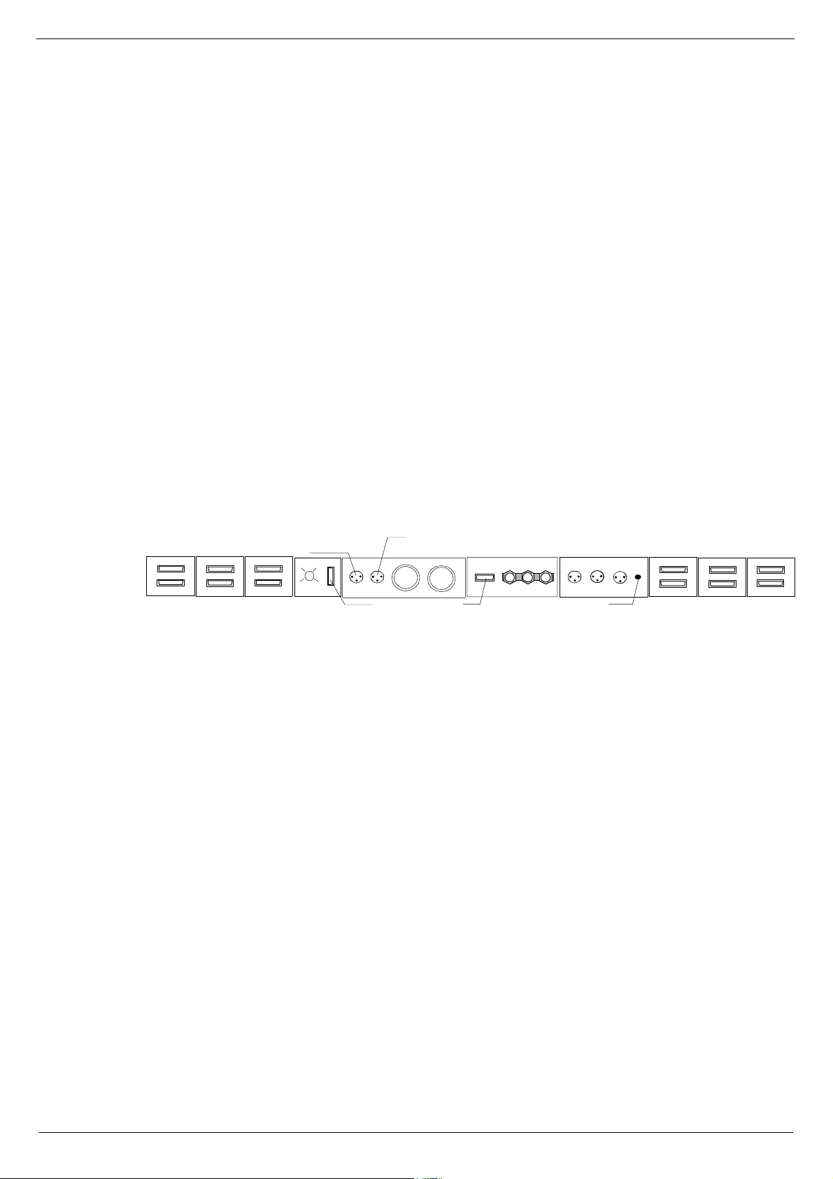
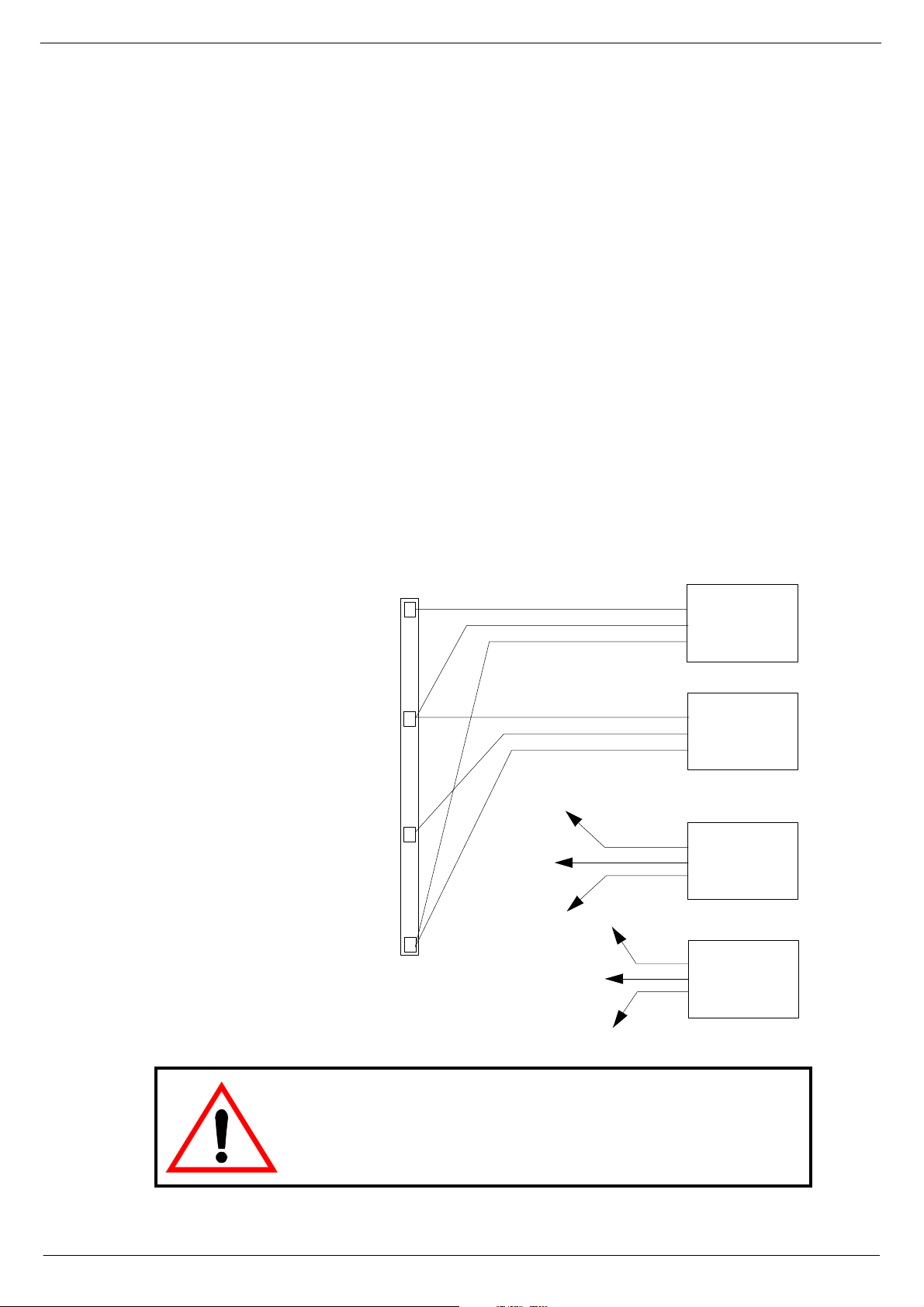
415 )UDPH#UHDU#FRQQH FWLR QV
HEADPHONES NEXT FRAME
4
5
AUDIO BUS
FIG 1-1. B-Type frame rear connections.
6
7
DATA BUS
FRAME TO FRAME
FRAME
SELECTOR
The connections on the B-Type console rear frame include the following (from left to
right):
■■■■
■■■■
■■■■
■■■■
■■■■
■■■■
■■■■
■■■■
■■■■
■■■■
■■■■
■■■■
■■■■
■■■■
■■■■
INPUT TO H EADPHO NES JACK SOC K ETS
COMMS TO CCM
PSU 1
PSU 2
PSU INDICATOR
FROM PFL NEXT LIGHTS
GND - 0 - FRAME
5 AMP FA N FUS E
Audio Bus - fr ame to frame, up to 4 frames can be connected.
Data Bus - fr ame to frame
Frame selector
Comms to CCM
PFL output to next frame.
PFL input from mod ule.
PSU1 co nnector
PSU2 co nnector
Output for monitoring of PSUs
GND - 0 - FRAME
Littlite input from PFL module.
Littlite output to next frame.
Littlite output to lights
Audio Bus
Data Bus
4
5
AUDIO BUS
FRAME TO FRAME
6
7
DATA BUS
The use of these co nnectors is describe d in 1.3.5 Main and extension frame power
connections, 1.4 Connecting the console frames and 1.5 Connect Console Automation System.
Revision B2005-2 B-Type
Page 10
1-2 Connecting the mixer systems
416 &RQQHFW#3RZHU#VXSSO\#V\VWHP V
41614 3RZHU#VXSSO\#V\VWHP#GHVFULSWLRQ
Cadac consoles are designed to allow th e use of two independent power supply systems in a redundant configuration – “main” and “backup ”. Both sets of power supply
units are used to power the console system so that under normal conditions, the
‘loa d’ is sh ar ed b etw e en th e “ m ai n” a nd “ bac ku p” PS U’s. I f a f a ul t o cc ur s in on e o f t he
power units ( c ausing it to ‘shut-down’), the remaining power unit will power the console.
For smaller B-Type consoles (consuming no more than 44A), it is possible to use the
8400 PSU. See 1. 3. 7 8 400 switch-mode power supp ly uni t.
One ±18V PSU and one +13V/+48V PSU is referred to as a “PSU System”.
Designate one pair of power supply units as “SYSTEM 1" and the other as “SYSTEM
2". PSU System 1 and PSU System 2 should be connected to the same
on the same ‘spur’, wherever possible. In situations where it is necessary to provide
a separate ‘feed’ to each PSU system pair, make sure that the cable lengths are the
same. This is to minimize any induced a.c. power input noise by ensuring that the
“EARTH IMPEDANCE” is the same for both PSU systems.
phase
and
$5($#%5$1&+#3$1(/
1#/
$5($#%5$1&+#3$1(/
*1'#%$5 *1'#%$5
0$,1#*5281'#5()(5(1 &(#($57+#(/(&752'(#6<67(0
$5($#%5$1&+#3$1(/
/
368#4$
-
-
-
-
1
(
/
1
(
/
1
(
/
1
(
368#4%
368#5$
368#5%
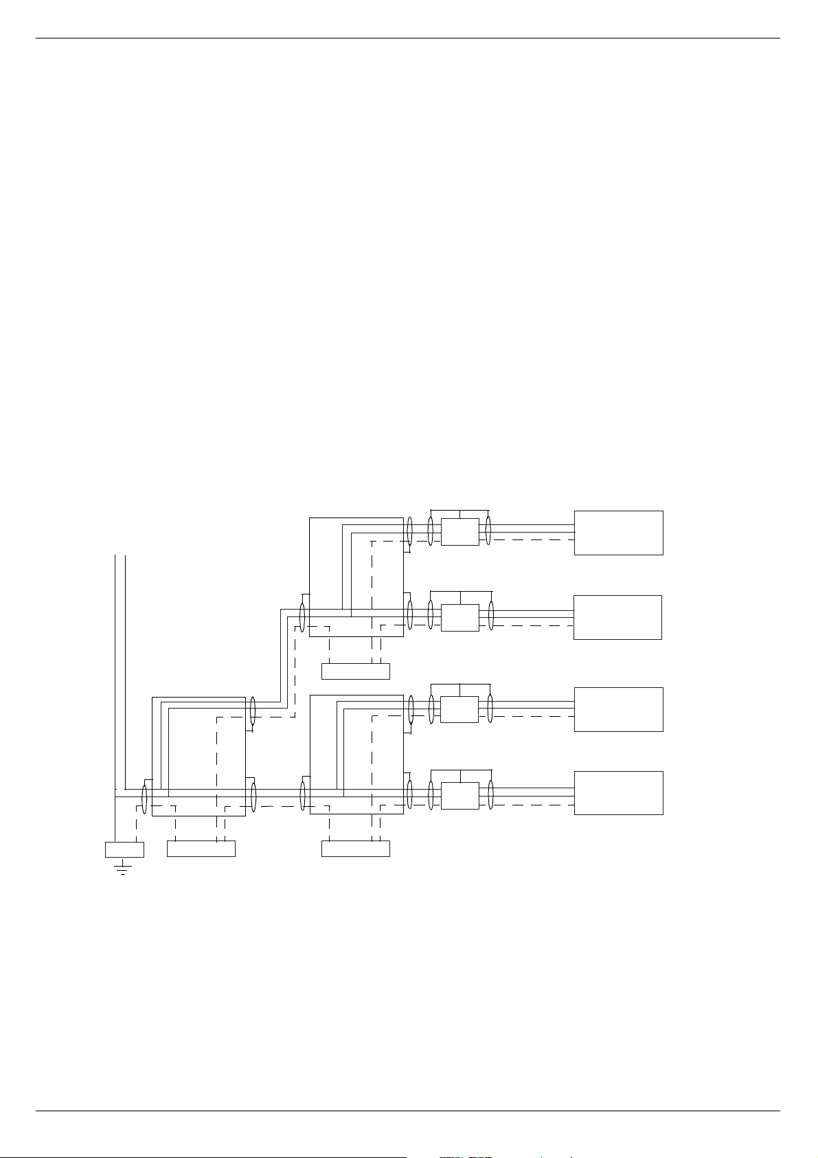
FIG 1-2. AC mains grounding diagram (single phase 200-240V)
B-Type Revision B2005-2
Page 11
Connecting the mixer systems 1-3
The a.c.-input connectors on each power supply unit have three conductors: ‘LIVE’
(brown), ‘NEUTRAL’ (blue) and ‘EARTH’ (yellow/green). For safety and electromagnetic compatibility considerations, it is essential that the ‘EARTH’ conductor is connected on all PSUs
continuous c ircuit to the “zero-signal reference potential” point in t he building. The
ZSRP point in a building is usually found near the place where the a.c. ‘mains’ supply
enters the building (often referred to as the “MAIN GROUND REFERENCE EARTH
ELECTRODE SYSTEM”). The basic concept for correct a.c. mains wiring distribution
is shown in figure 1-1. If you need further information about this complex subject,
please refer to “Grounding Systems and their Implementation” by Charles Atkinson
and Philip Giddins published in the AES Journal Vol. 43, No. 6 – June 1995.
The grounding scheme in CADAC consoles is designed to meet the rigorous EEC
Elec tromagne tic Compatibility
induced in the console frame(s) is directed to the “local” ZSRP, which is the metalwork of the power supply units. In order to take full advantage of the “RF noise immunity” capability of the CADAC system, PSU a.c. mains cables an d the a.c. mains
supply EARTH conductor must be connecte d correctly.
the a.c. supply has an ‘EARTH’ conductor that has a
and
requirements (EMC Directi ve - 1996 ). Any RF noise
41615 $&#SRZHU#UHTXLUHPHQWV
CADAC power supply units are designed to run from a minimum of 208 V up to a
maximum of 260V, 50/60Hz a.c. In many parts of the world the normal a.c. singlephase supply is 100-127V, this means that the CADAC power supply units must be
connected across two of the phases in the three-phase a.c. supply, see 1.3.4 Connecting to a 3-phase outlet.
41616 6ZLWFK00RGH#3RZHU#6XSSO\#8QLWV
CADAC 8019 and 8020 switch-mode power supply units are designed to run from a
minimum of 208V up to a maximum of 260V a.c, 50/60Hz.
The 80 19 “18 V ” uni t is r a te d at 10 0A per r a il an d the 8 020 “1 3V” un it is rat ed at 100A.
See also Appendices, B. Switch-Mode Power Supply Units,
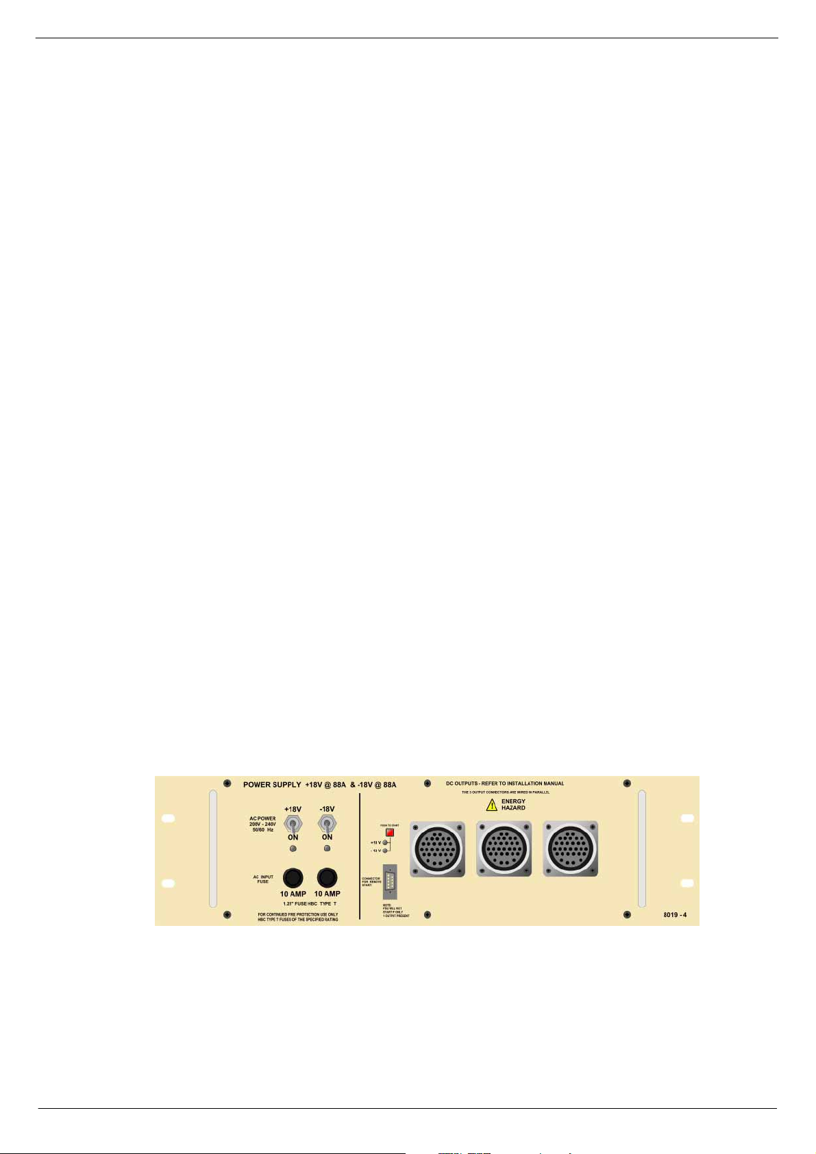
;34<#´4;9µ#VZLWFK0PRGH#SRZHU#VXSSO\#XQLW
The ol der version of 8019 ±18v unit is based on two ADVANCE F20006 ‘powerblocks’, with additional circuitry as shown on CADAC dr awing number C3.8015. The
new version is based on PowerOne PSUs (serial number 3494 9 onwards).
The a .c. input is connected to the PSU via a 3-core cable, CMA reference 3183TQ –
BASEC approved, rated at 20A.
FIG 1-3. 8019 power supply unit
Revision B2005-2 B-Type
Page 12
1-4 Connecting the mixer systems
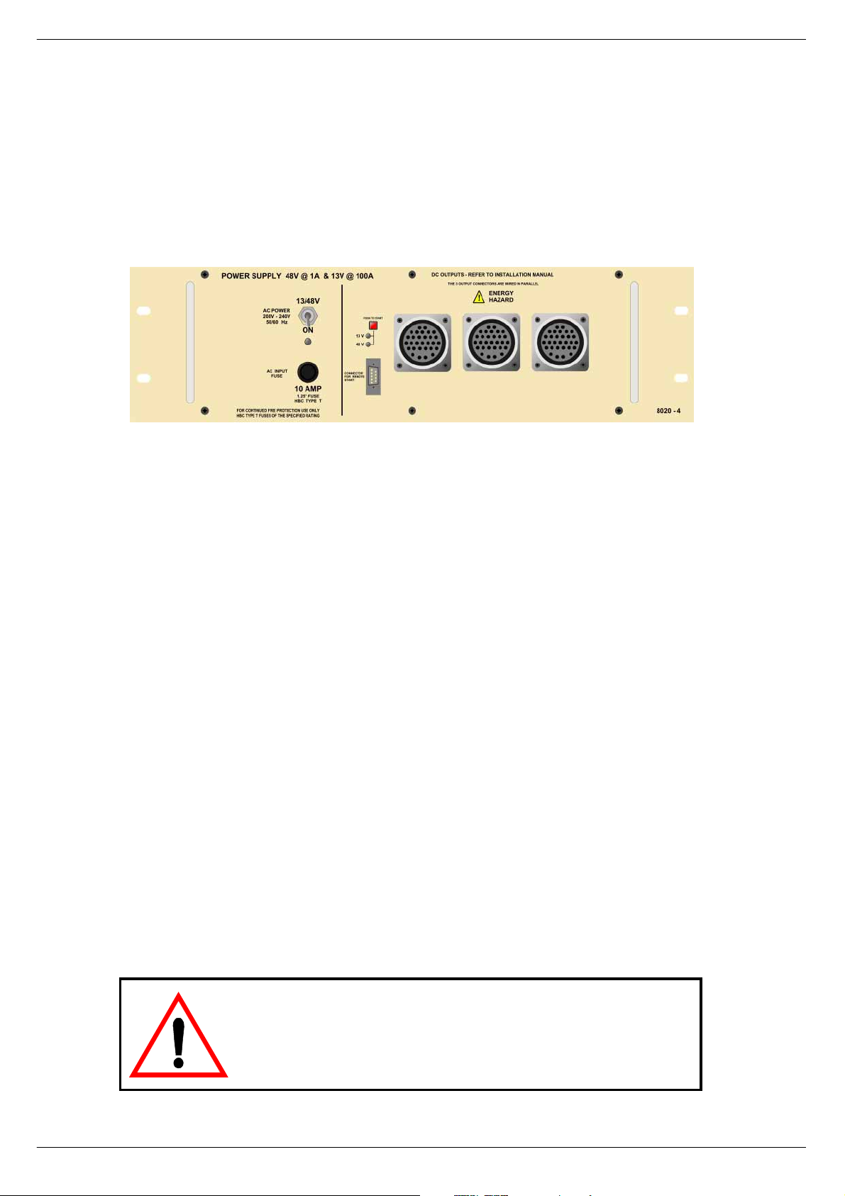
;353#´469µ#VZLWFK0PRGH#SRZHU#VXSSO\#XQLW
The ol der version of 8020 +13v/48v unit is based on one ADVANCE F20006 ‘pow erblock’, with additional circuitry as shown on CADAC drawing number C3.8016. The
new version is based on Pow erOne PSUs (serial numb er 34949 onwards).
The a .c. input is connected to the PSU v ia a 3-core cable, CMA reference 3183TQ –
BASEC approved, rated at 20A.
FIG 1-4. 8020 power supply unit
5HSODFLQJ#D#SRZHU#VXSSO\#XQLW
If replacing a switch-mode power supply unit is required, please note the following:
Make sure that the power supply s ystem’s power switches are in t he position
■■■■
OFF and disconnected from the mains.
The work should only be carried out by a suitably qualified electrician.
■■■■
Be careful to observe corr ect polarity when connecting the new PSU.
■■■■
Note that a console must never have one voltage without the other, f or exam ple
■■■■
+18V must never be fed into the console without -18V.
When switching the power supply system back ON after replacement has taken
place, make sure that both LEDs on the front of the PSU-system come on. If only
one LED comes on, let go of the ON push-button immediately. Failure to do so may
lead to fire hazar d and major damage to th e console.
NO TE:
Under no circumstances, should the 8019 or 8020
PSU be used without a SAFETY EARTH connection. Failure
to follow this instruction is both a fire and safety hazard.
B-Type Revision B2005-2
Page 13
Connecting the mixer systems 1-5
41617 &RQQHFWLQJ#WR#D#60SKDVH#RXWOHW
Connection to a 3-phase outlet is required on sites where the system voltage
between any one of the phases and neutral is 100-127V and the voltage between
any two of the phases is 20 0-240V. Before connecting to any 3-phase outlet, please
refer to a qualified electricia n who understands your particular installation and the
local safety and wiring regulations. Under no circumstances should the 8019 and
8020 switch-mode power supply units be operated without the green/yellow safety
earth conductor connected to the building safety earth conductor system. Each
power unit is equipped with an input supply filter whose reference ground conductor
is the chassis. Failure to connect the green/yellow safety earth conductor to the correct eart h/ground building reference is a safety and fire hazard.
1. Connect the LIVE (Brown) conductor on the “system 1” 8019 unit to the phase 1
(L1, RED) terminal on the 3-phase power outlet connecto r.
2. Connect the NEUTRAL (Blue) conductor on the “system 1” 8019 unit and the
LIVE (Brown) conductor on the “system 1” 8020 unit to the Phase 2 (L2, YELLOW) terminal on the 3-phase power outlet connector.
3. Connect the NEUTRAL (Blue) conductor on the “system 1” 8020 unit to the
Phase 3 (L3, BLUE) terminal on the 3-phase power outlet connector.
4. Connect the EARTH (Yellow/Green) conductor on the “system 1” 8019 unit and
the EAR T H ( Yellow/ Gr e en) co nd uc to r on the “sys te m1 “ 8 02 0 unit to th e SA FET Y
EAR TH (Yellow/Green) terminal on the 3-phase power outlet connector.
5. Repeat 1-4 for the “ system 2” power units.
3+$6(#4#+/4/#5(',
3+$6(#5#+/5/#<(//2:,
3+$6(#6#+/6/#%/8(,
6$)(7<#($57+
<(//2:2*5( (1
/5
6$)(7<#($57+
/4
/5
/4
/LYH
1HXWUDO
(DUWK
/LYH
1HXWUDO
(DUWK
/LYH
1HXWUDO
(DUWK
/LYH
1HXW UDO
(DUWK
;34<
;353
;34<
;353
FIG 1-5. Connecting to a 3-phase outlet
(100-127V/200-240 system voltages)
NOTE:
Connection between two phases in a 3-phase outlet should under no
6$)(7<#($57+
circumstances be carried out where the single-phase voltage (the voltage
between one of the phases and neutral) exceeds 127V. The installation
should be carried out by a qualified electrician who understands your particular installation and the local safety and wiring regulations.
Revision B2005-2 B-Type
Page 14
1-6 Connecting the mixer systems
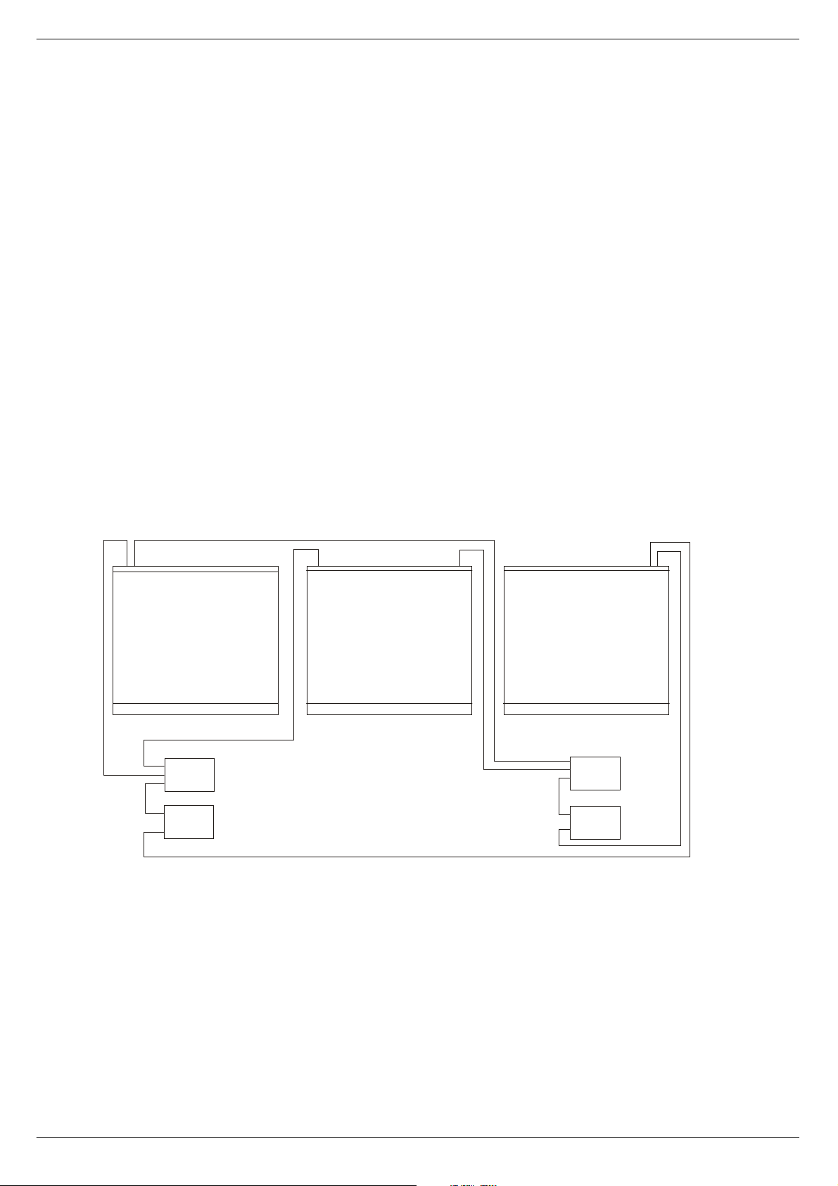
41618 0DLQ#DQG#H[WHQVLRQ#IUDPH#SRZHU#FRQQHFWLRQV
See fig 1-4 below for schematics of the frames power connections.
1. Using a short U-LINK cab le (supplied), connect one of the outputs on the ±18V
PSU to one of the outputs on the +13V/+48V PSU in the “SYSTEM 1" power
supply rack. This operation “links” the d/c outputs on both power supply units in
the rack so that ±18V, +13V and +48V is available on all remaining output connectors on eith er power unit.
2. Co nn ec t t he seco nd s ho rt “U -LI NK” c abl e ( s up plie d) b etw e en the ± 18 V PS U an d
the +13V/+48V PSU’s in the “SYSTEM 2" power supply rack.
3. Connect a PSU cable between the “SYSTEM 1" rack and the “PSU SYSTEM 1"
connector on the MAIN FRAME.
4. Connect a PSU cable between the “SYSTEM 2" rack and the “PSU SYSTEM 2"
connector on the MAIN FRAME.
5. Connect a PSU cable between the “SYSTEM 1" rack and the “PSU SYSTEM 1"
connector on the EXTENSION FRAME 1.
6. Connect a PSU cable between the “SYSTEM 2" rack and the “PSU SYSTEM 2"
connector on the EXTENSION FRAME 1.
7. Repeat procedures 5 and 6 for EXTENSION FRAME 2 (a 3 frame console).
368#6<67 (0#4#+“4;9,
368#6<67(0#4#+7;92.469,
368#6<67(0#5#+“4;9,
368#6<67(0#5#+7;92.469,
FIG 1-6. Power connections
B-Type Revision B2005-2
Page 15
Connecting the mixer systems 1-7
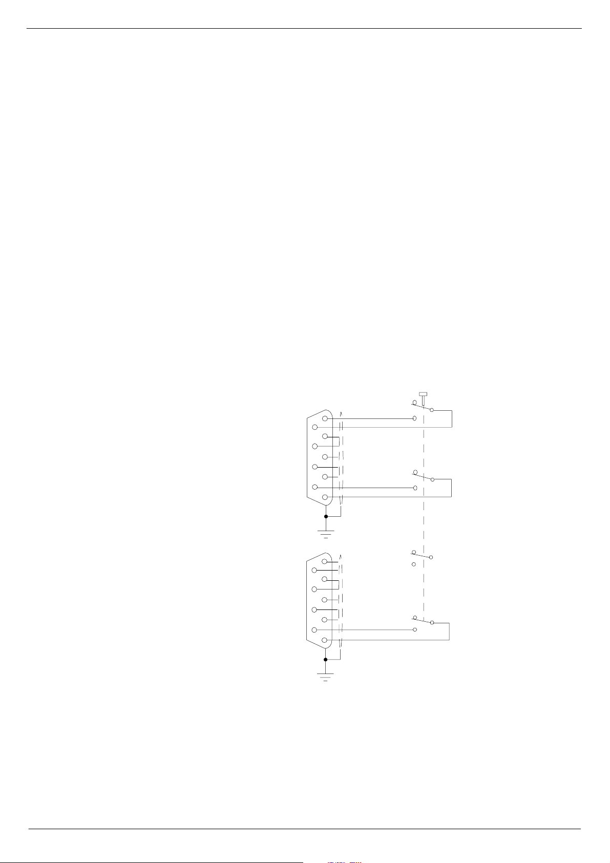
41619 ;34<#DQG#;353#FRPELQHG#5HPRWH#VWDUW
Each 801 9 and 8 02 0 s w it ch- mod e p o we r supp ly is fi t ted wi th a f ron t p an el mo un ted 9
way ‘D-type’ connector. This connector is labelled “Connections for Remote Start”.
You may connect a single remote start switch to each unit, have one switch start a
“system” pair, or wire up a single switch to start “system 1” and “system 2” all at the
same time.
Fig 1-5 applies to 8019 and 8020 PSUs up to serial number 34949 and shows the
circuit for starting up a “s ystem” pair with a single switch. This has pro ved to be the
most popular method of connecting the remote start facility. This circuit can easily be
extended to provide a single switch remote four all four PSUs if required.
For 8019 and 8020 PSUs from serial number 34950 onwards, see fig 1-6 and 1-7.
NOTE:
The remote must be a ‘momentary’ type. You will need a two-pole switch for a
■■■■
single PSU, a four-pole switch for a “system” pair, or a six-pol e switch for con trolling
all four units.
The remote switch(es) must be mounted on a metal panel.
■■■■
Use shielded cable for the remote switch wiring.
■■■■
The 9-way ‘D-type’ f ree plug must have a conductive shell. This is to ensure that
■■■■
the cable shield connects directly to the PSU unit chassis.
Connect the cable shield to the metal panel where the remote start switch(es)
■■■■
are mounted.
TO CONNECTION
FOR REMOTE START
ON 8019 FRONT PANEL
TO CO NN E C TIO N
FOR REMOTE START
ON 8020 FRONT PANEL
CUP/TAG SIDE
5
9
4
8
3
7
2
6
1
5
9
4
8
3
7
2
6
1
PANEL MOUNTED 4-POLEVIEW FROM SOLDER
MOMENTARY SWITCH
NOTE: CABLE SCREEN IS
CONNECTED AT BOTH ENDS
FIG 1-7. Remote start of 8019/8020 up to serial number 34950
Great care must be taken with the wiring of the switch(es) to ensure that no short-circuits can occur between any two power supply units.
Revision B2005-2 B-Type
Page 16
1-8 Connecting the mixer systems
VIEW FROM SOLDER
CUP/TAG SIDE
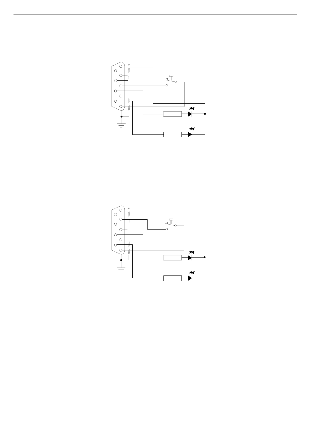
FIG 1-8. Remote start of 8019 PSU
(from se rial number 34950)
5
9
4
8
3
7
2
6
1
VIEW FROM SOLDER
CUP/TAG SIDE
5
9
4
8
3
7
2
6
1
“START” MOMENTARY PUSH BUTTON
18V
300R
OVER
TEMPERATURE
300R
POWE R F AILURE
“START” MOMENTARY PUSH BUTTON
13V
FIG 1-9. Remote start of 8020 PSU
(from se rial number 34950)
300R
OVER
TEMPERATURE
300R
POWER FAILURE
B-Type Revision B2005-2
Page 17

Connecting the mixer systems 1-9
4161: ;733#VZLWFK0PRGH#SRZHU#VXSSO\#XQLW
FIG 1-10. 8400 power supply unit.
CADAC 8400 switch-mode power supply units are designed to run from a minimum
of 208V up to a maximum of 260V a.c, 50/60Hz.
The 84 00 is rated thus +13V@92A, ±18V@44A and 48V@5A.
The a .c. input is connected to the PSU via a 3-core cable, CMA reference 3183TQ –
BASEC approved, rated at 20A.
The 8400 unit is based on one POWER ONE RPMS-ETETGDGD1ETK Pow er block,
with additional circuitry as shown on CADAC drawin g number C3.8397.
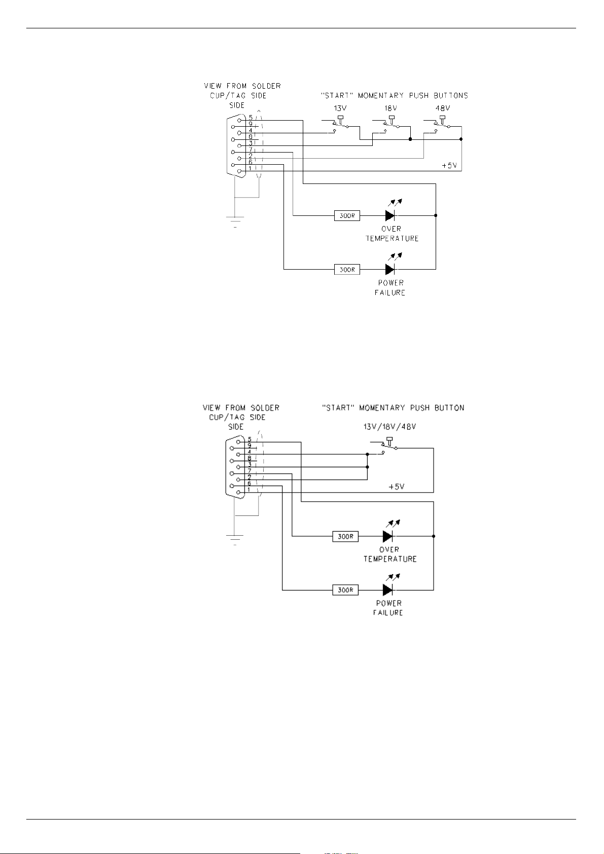
4161; 5HPRWH#VWDUW#RI#;733#368
Each 8400 switch-mode power supply provides the follo wing outputs: 13v, ±18v and
48v. Each PSU is fitted with a front panel mounted 9-way 'D-type’ connector labelled
‘Connections for Remo te Start’. If a remote start facility is used, Power Failure and
Over-Temperature LEDs may also be fitted with the remote start switches if required.
Fig 3-15 shows the circuit for starting up a “system” with a single switch. This has
proved to be the most popular method of connecting the remote start facility. This circuit can easily be extended to provide a single switch remote four all four PSUs if
required. If muliple switches are to be used, see fig 3-14.
NOTE:
The remote start switch must be a ‘momentary’ type. You can use 3 separate sin-
■■■■
gle pole switches for each Power Supply to turn on 13v,±18v and 48v outputs of the
PSU alternatively use one single pole for the whole lot.
The remote switch(es) must be mounted on a metal panel.
■■■■
Use shielded cable for the remote switch wiring.
■■■■
The 9-way ‘D-type’ f ree plug must have a conductive shell. This is to ensure that
■■■■
the cable shield connects directly to the PSU unit chassis.
Connect the cable shield to the metal panel where the remote switch(es) are
■■■■
mounted.
Revision B2005-2 B-Type
Page 18
1-10 Connecting the mixer systems
FIG 1- 11. R emote s tart o f
PSU 8400 with multiple
switches.
FIG 1-12. Remote start of PSU
8400 with a single switch
Great care must be taken when wiring the s witch(es) to ensure that no short-circuits
can occur between any two power supply units.
B-Type Revision B2005-2
Page 19

Connecting the mixer systems 1-11
417 &RQQHFWLQ J#WKH#FRQVROH#IUDPHV
41714 $XGLR#%XV#2#'DWD#%XV#&RQQHFWLRQV
If the console is used in a multi-fram e configuration then the busses need to be connected in a ‘daisy chain’ fashion.
four audio and two data busses plus fader bus (see fig 1-13). The bus cables are
simply linked between s imilar connectors on the end of the nearest f rame.
Make sure that each frame has its “Frame Select” switch set to a different number.
Each end
of a frame has seven bus connectors -
FIG 1-13. Audio/Data Bus connections.
See also appendix A. Impor tant information regarding EMC.
41715 )DGHU#FRPPXQLFDWLRQV
When motor faders are used in extension frames, a 9-way “FADER COMMS” cable
must be connec ted between the CCM c onnectors shown (see fig 1-3) an d the
COMMS input on the extension frame rear panel.
Extension frames fitted with motor- faders r equire control dat a from the CCM. Three
9-pin femal e connectors Three 9-pin female connectors located on the rear panel of
the CCM are connected direct ly
comms’ cable. The frame containing the CCM sends motor data fader data, via the
7303 interface module (always mou nted directly below the CCM on J-type consoles).
Thus , a 3 frame console wou ld requir e two “FADER COMMS” cabl es:
4
5
AUDIO BUS
FRAME TO FRAME
6
7
DATA BUS
FRAME
COMMS TO CCM
SELECTOR
to the extension frame using the supplied ‘fader
“FADER COMMS on EXTENSION FRAME 1 TO “FADER COMMS 2” on CCM
“FADER COMMS on EXTENSION FRAME 2 TO “FADER COMMS 3” on CCM
41716 3)/
PFL mixing amplifiers ar e located in the “Oscillator /Communications” module. There
are two PFL outputs:
PFL Direct is a line level output that appears on an XLR 3-32 connector on the
■■■■
rear panel of the OSC/Comms module, labelled “PFL DIRECT”;
PFL to H eadphone s is a high level output suitable for driving headpho nes that
■■■■
appears on an XLR 3-32 connector
panel of the OSC/C omms module, labelled “PFL TO HP”.
The PFL to Headph ones signal can be connected to the TRS jack sockets mounted
on the front of the console frame by using the “OSC/COMM TO FRAME” cable supplied. This cable has a male XLR 3-pin connector on one end and a female XLR 3pin on the other end. Connect one end of the “Oscillator/ Communications” module’s
“PFL TO HP” connector and the other end to the rear frame connector labell ed
Revision B2005-2 B-Type
a TRS jack socket connector on the rear
and
Page 20

1-12 Connecting the mixer systems
“FROM PFL HEADPHONE XLR”.
Additional inter-frame connec tions are required to enable the PFL signals from modules i n extens ion (side) frames to be monitored. Use the cable(s) labelled “PFL
FRAME TO FRAME” to interconnect two or more frames:
Connect one en d of a “PF L FRAME TO FRAME” cable to the connector labelled
■■■■
“TO NEXT FRAME” on the console frame containing the “Osc/Communications”
module.
Connect the other end of a “PFL FRAME TO FRAME” cable to the connector
■■■■
label led “FROM PFL HEADPHONE XLR” on the next frame.
Repeat this procedure for all other frames in the console system.
41717 /LWWOLWHV
Surface illumination of the console is provided b y the use of two or more “Littlite”
units that plug into the top bar of the console frame. Control for the “Littlites” - on/off
and in tensity - is located on the “Oscillator/Communications” mod ule. The variable
voltage power supply is mounted inside the console fr ame.
Two cables are requir ed to inte rconnect the “Litt lite” controls, t he variable voltage
power supply and the lamp units.
Connect one of the cable labelled “OSC TO LITTLITES” to the connector on the
■■■■
rear panel of the “Oscillator/Communications” module labelled “LITTLITES” (this
cable has 4-pi n XLR male and female connectors).
Connect the other end of the cable labelled “OSC TO LITTLITE” to the connector
■■■■
on the rear panel of the console frame labelled “F ROM PFL MOD ULE”;
Connect one end of the cable labelled “LITTLITE FRAM E TO BAR” to the con-
■■■■
nector on the rear panel of the console frame labelled “TO LIGHTS” (this cable has a
4-pin male XLR connector at one end and a 5-pin XLR connector at the other end).
Connect the ot her end of the cabl e labelled “LITTLITE FRAME TO BAR” to the
■■■■
5-pin XLR-connector mounted at the rear of the top bar on the console fra m e.
Additional inter-frame connec tions are required to enable the LITTLITE control signals to be delivered to any extension frame(s) in the console system. Use the
cable(s) labelled “LITTLITE FRAME TO FRAME” to interconnect two or more frames.
Connect one end of a “LITTLITE FRAME TO FRAME” cable to the connector
■■■■
labelled “TO NEXT FRAME” on the console frame containing the “Oscillator/Communications” module;
Connect the other end of a “LITTLITE FRAME TO FRAME” cable to the connec-
■■■■
tor labelled “FROM PFL MODULE” on the next frame;
Connect one end of a cable labelled “LITTLIT E FRAME TO BAR” to th e connec-
■■■■
tor on the rear panel of the console frame labelled “TO LIGHTS” (this cable has a 4pin male XLR connector at one end and a 5-pin XLR connector at the other end.
Connect the ot her end of a cable labelled “LITTLITE FRAME TO BAR” to the 5-
■■■■
pin XLR connector mounted at the rear of the top bar on the console frame.
Repeat this procedure for all other frames in the console system.
41718 368#,QGLFDWRU
Two sets of four LEDs are incorpora ted into the CCM front panel to give the operator
visual indication that the “main” (PSU System 1) and “backup” (PSU System 2)
power supply units are working correctly. A cable, labelled “PSU IND.” is supplied to
interconnect the CCM and t he console frame.
Connect one end of the “PSU IND” cable to the “PSU IND” 15-way male D-sub
■■■■
connector on the CCM.
Connect the other end of the “PSU IND” cable to the “PSU IND” 15-way female
■■■■
D-sub connector on the rear con s ole frame adjacent to the two multi-pin power input
connectors.
B-Type Revision B2005-2
Page 21
Connecting the mixer systems 1-13
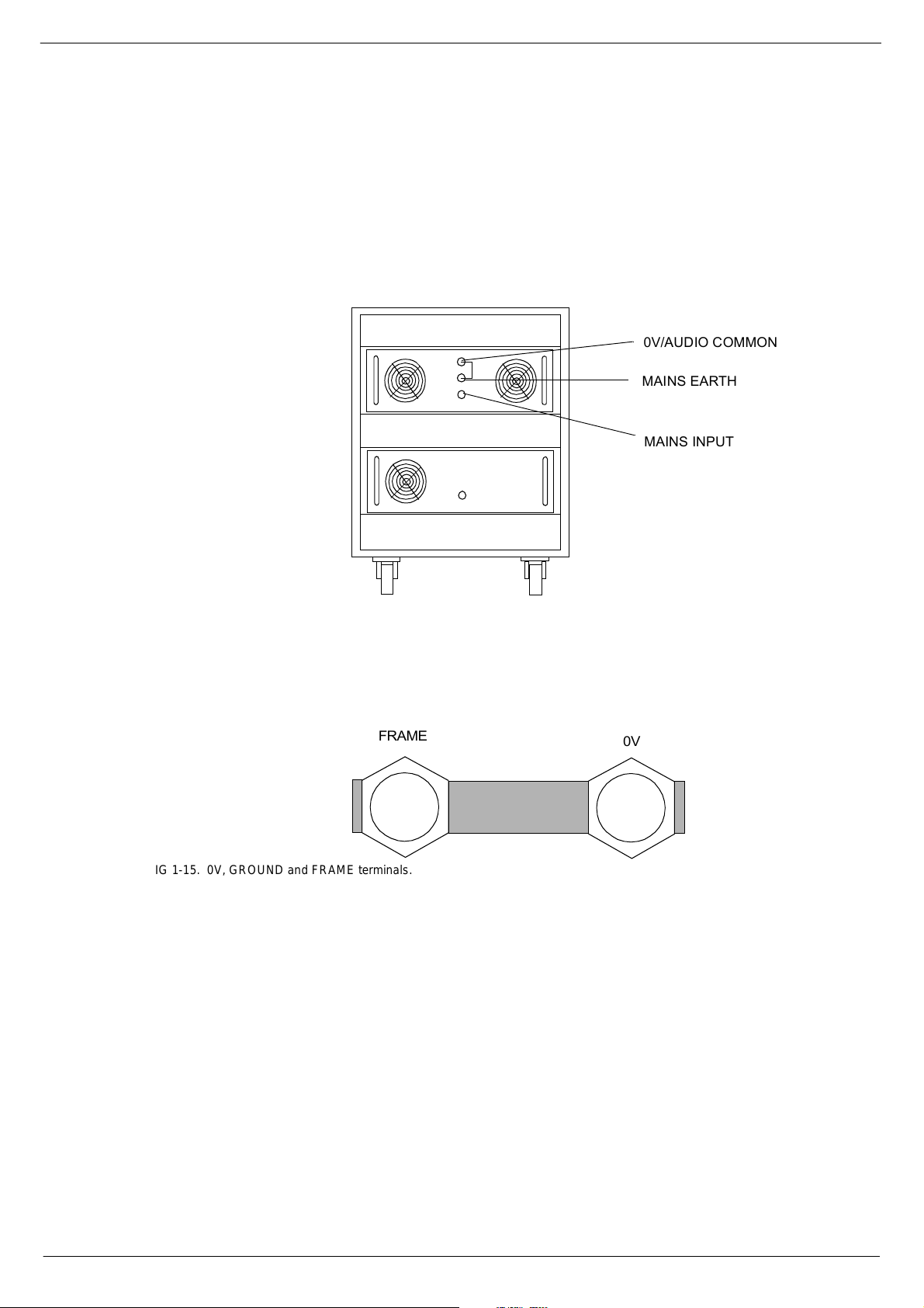
41719 (DUWK/#39#DQG#)UDPH#&RQQHFWLRQV
Figure 1-6 shows the rear panels of the power su pply units in a single PSU system.
Under normal conditions, the 0V and Mains-Earth terminals can be connected on
both PSU systems. However, if the a.c. input lines to each pair of PSU’s has a different length, you may find that t he 0V and Mains -Earth terminals can only be linked on
set of power supplies, for minimum system noise.
one
FIG 1-14. PSU system.
The 0V or FRAME termi nals on a PSU need
or FRAM E connections on con s ole frames. The shielded po wer supply cables are
connected to the frame at both ends.
be dir ec tly co nn ec te d t o th e 0 V and/
not
392$8',2#&20021
0$,16#($57+
0$,16#,1387
In addition to the terminals on the back of the PSUs, there are
nections on the rear of each console f rame. The shorting-bar link between the 0V
and “FRAME” terminals on each frame
large diameter ‘frame-link’ cables (supplied with multi-frame consoles), must be connected. Always make sure that ‘frame-link’ cable nuts are tightened against the copper bar.
be conn ected. For minimum noise, the
must
0V
and
FRAME
con-
)5$0(
IG 1-15. 0V, GROUND and FRAME terminals.
The 0V and FRAME t erminals are linked in the factory with a copper bar. This bar
should never be removed when the console is in normal use. Note that
cannot be delivered from the input modules to the 48V bus if the copper bar is
Power
missin g, beca us e t he scre en ed mic rop ho ne input ca b l es w il l not be te rmina te d. I t wil l
also cause damage to the motor faders.
39
Phantom
Revision B2005-2 B-Type
Page 22
1-14 Connecting the mixer systems
418 &RQQHFW#&RQVROH#$XWR PD WL RQ#6\VWHP
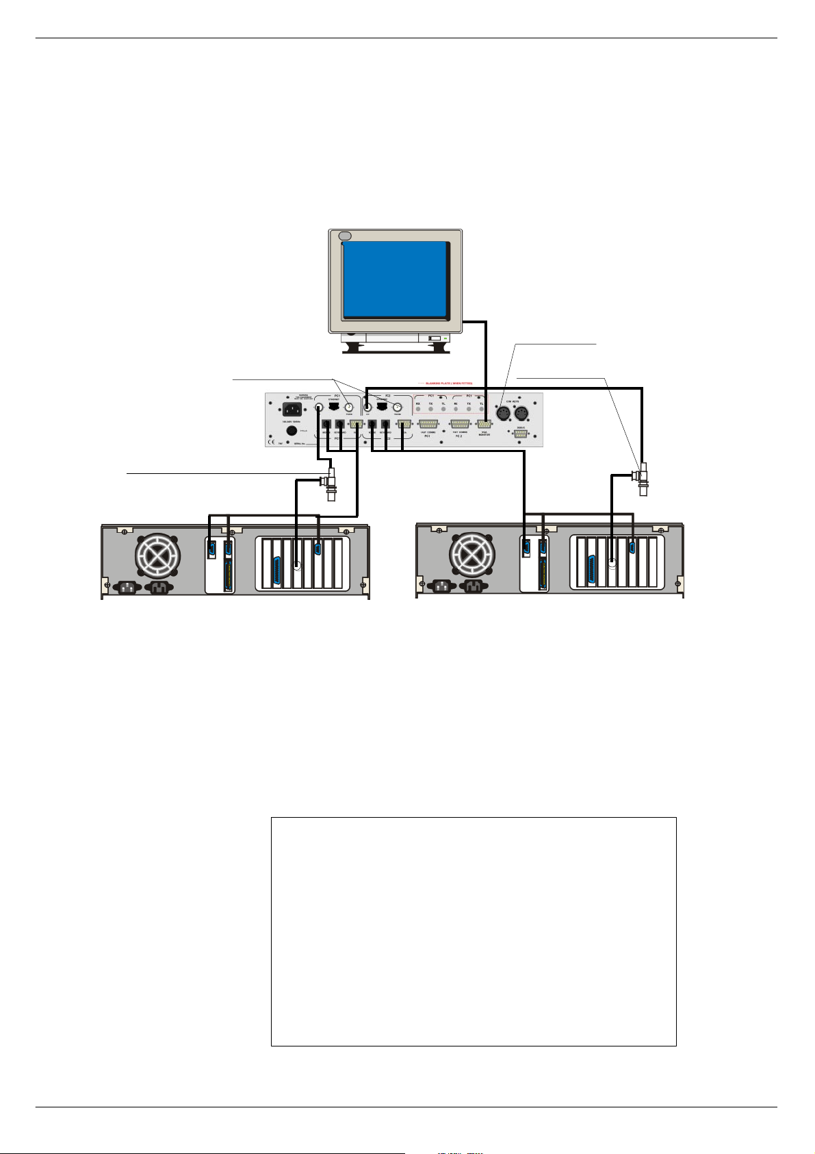
41814 &RQQHFWLRQV#0#%1&
Figu res 1 - 9 be lo w a nd 1- 1 1 s how h o w t o c onn ec t th e S éan ce box to th e c on sol e an d
the co mputers running SAM., BNC type connection.
7R#UHPRWH#3.1
83#RKP#WHUPLQDWLRQ
(WKHUQHW#WHUPLQDWHG#DW#3&#HQG
0RXVH
.H\ERDUG
9*$
(WKHUQHW#WHUPLQDWHG#DW#3&#HQG
0RXVH
.H\ERDUG
9*$
3&4#ZLWK#(WKHUQHW#FDUG 3&5#ZLWK#(WKHUQHW#FDUG
FIG 1-16. Séance rear panel connections for BNC
41815 (WKHUQHW#0#%1&
The Séance box communicates with the PCs over a 10Base-2 Ethernet connection
via a 50 ohm BNC cable terminated at each end with a 50 ohm terminator. The
Séance box has two BNC connectors for each P C interface, w hich are wired in parallel in side. A 50 ohm terminator plugs into the BNC socket labelled TERMINATOR
and th e Ethernet cable plugs into the BNC socket labelled COMPUTER. A t erminator and T-piece are used to connect the Ethernet cable to the PC.
0LQLPXP#VSHFLILFDWLRQ#IRU#D#3&#XVHG#ZLWK#WKH#############
6RXQG#$XWRPDWLRQ#0DQDJHU#6RIWZDUH
To run the Sound Automation Manager software requires a PC with at least the
performance and peripherals as listed below:
PC Pentium 133 or later or compatible computer
Windows ®’98 (second edition), 2000, XP or XP Pro
Graphics card 1024 x 768 pixels, 16 bit colour or bette r
Ethernet interface 10Mbit/sec with 10base2 connector (BNC)
128MB RAM
20 MB free hard disk space
PS/2 keyboard (older 5-pin DIN keyboard can be used with adapter)
PS/2 mouse or pointing device (9-pin’D’-serial devices cannot be used) PS/2
keyboard (o lder 5-pin DIN keyboard can be used wit h adapter)
B-Type Revision B2005-2
Page 23
Connecting the mixer systems 1-15
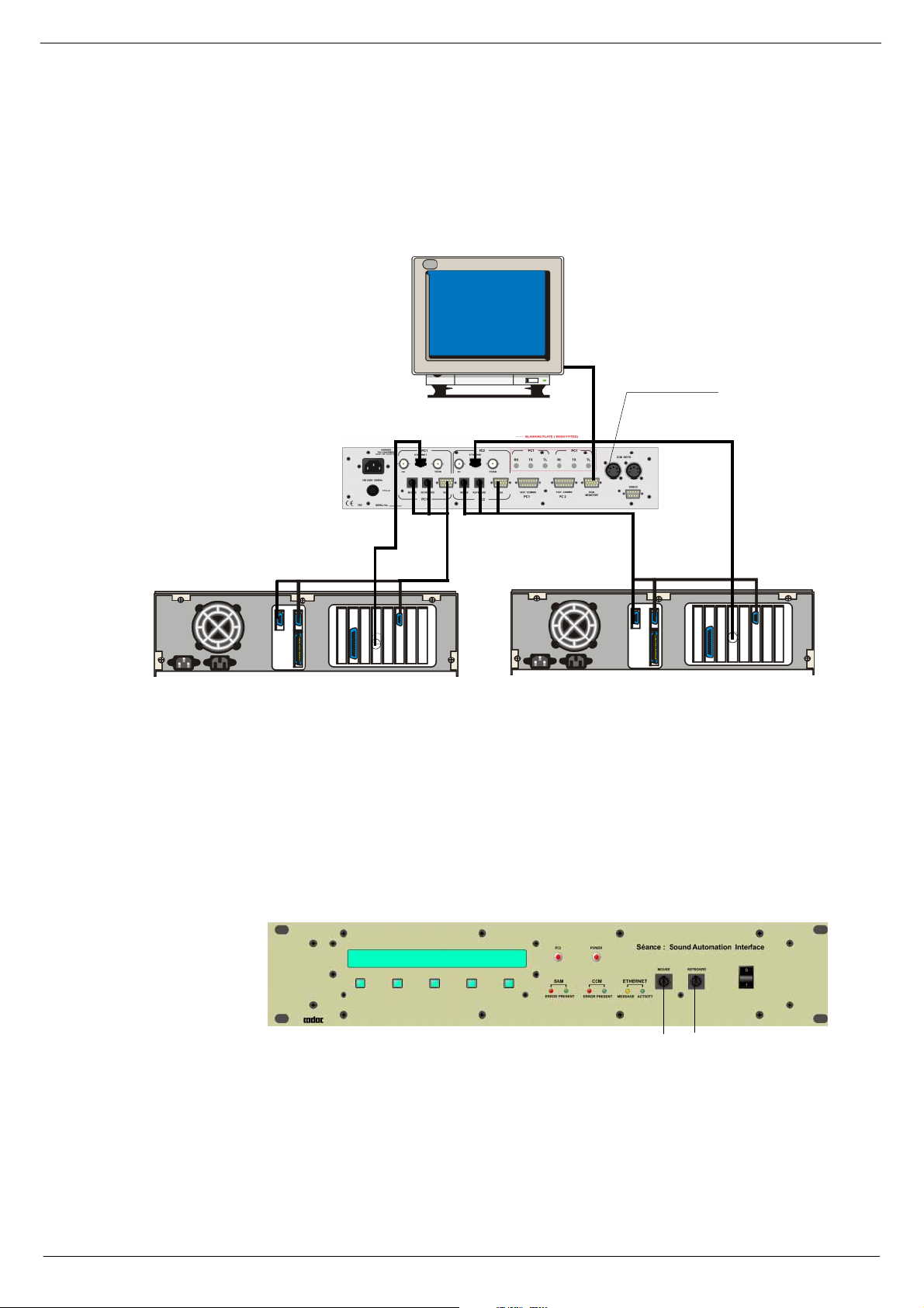
41816 &RQQHFWLRQV#0#5-78
Figu re 1-10 below and fig 1-11 show how to con nect the Seance bo x to the cons ole
and the computers running SAM, using RJ45 connection.
7R #UHPRWH#3.1
3&4#ZLWK#(WKHUQHW#FDUG
FIG 1-17. Séance rear panel connections for RJ45
41817 (WKHUQHW#0#5-78
The Seance box can also communicate with the PC via an RJ45 connector depending
on the type of Ethernet-card in the computer. The Séance box has two RJ45 connectors, one for each PC interface. These connectors should be connected directly into
a comp uter. It is also poss ib l e to c onn ec t th e R J45 so c k ets t o a hu b . F or d eta il s a bo ut
this , contact CADAC technical support.
0RXVH
.H\ERDUG
9*$
0RXVH
.H\ERDUG
9*$
3&5#ZLWK#(WKHUQHW#FDUG
FIG 1-18. Séance front panel connections - BNC and RJ45
0RXVH .H\ERDUG
41818 0RXVH
Each PC has a ‘one-to-one’ PS2 mouse cable, which connects betwe en the PC’s
mouse port and the mouse connector on the r ear panel of the Séance box. The
mouse plugs into the mouse connector on the front panel of the Séance box.
Revision B2005-2 B-Type
Page 24

1-16 Connecting the mixer systems
41819 .H\ERDUG
Each PC h as a ‘ o ne-o ne ’ PS2 k e yboa r d c ab le , whi ch co nn ects be tw ee n t he PC ’ s k e yboard port and the keyboard connector on the rear panel of the Séance box. The keyboar d connects into the keyboard connector on the front pa nel of the Séance box.
Converters are supplied to connect to a 5-pin DIN keyboard and 5-pin DIN connectors
on the PC.
4181: 9*$
Each PC has a VGA cable connected between the c omputer’s VGA output and the
corresponding VGA connector on the rear panel of the Séance box. The VGA monitor
cable plug s int o the VGA con ne c tor.
4181; &&0#NH\V
The Séance interface reads the PC2 switch on the console’s CCM. The 5-pin XLR
connectors are paralleled together inside the Séance. A ‘female-female, on e-one cable ’ conn ects to the k eys conne ctor on th e CCM an d the ot her ca n be us ed to c onnec t
to remote PREV and NEXT keys if required.
4181< )DVW#FRSSHU#FRPPXQLFDWLRQV
CADAC’s 15 way “f ast copper communications” cables are used to connect between
the Séance box’s fast comms connectors and the CCM. The cable plugged into Fast
comms PC1 on the Séance box must be connected to PC1 on the CCM.
418143 'HEXJ#SRUW
The debug port is standard PC 9-pin serial port that can be used to access the
Séance box’s computer.
418144 0DLQV
The Séance box has a universal power supply and can be connected to AC mains 100
– 240V, 50/60Hz.
418145 )XVH
20mm 315mA fuse.
B-Type Revision B2005-2
Page 25
Connecting the mixer systems 1-17
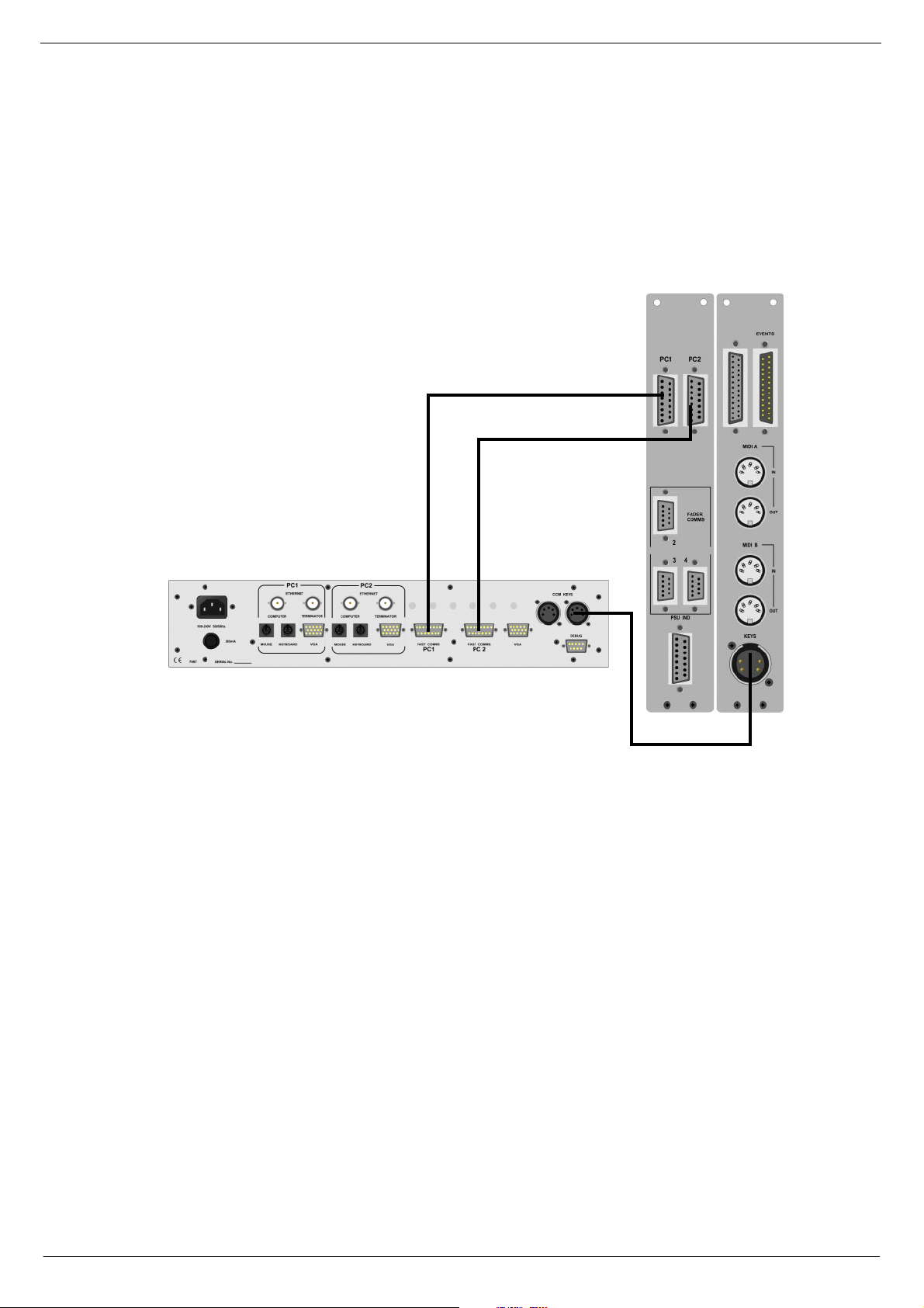
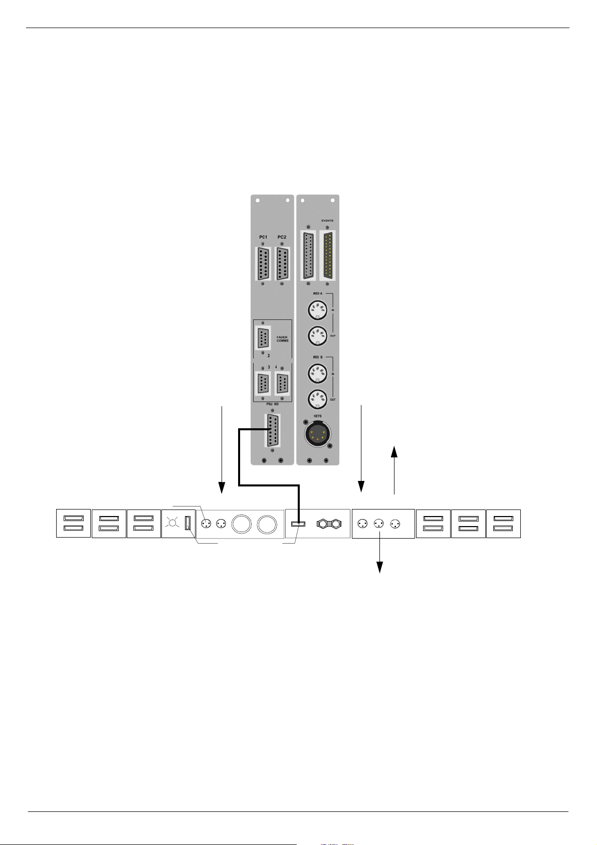
418146 &RQQHFW#6pDQFH#WR#FRQVROH
Figure 1-12 below shows how to connect the Séance Interface to the CCM in the
main co nsole.
FIG 1-19. Connect Séance to CCM.
Using the cables supplied, make the following connections:
1. CCM PC1 to Séance box PC1.
2. CCM PC2 to Séance box PC2.
3. CCM KEYS to Séance box KEYS.
Details on Seance set-up can be found in the Seance I nterface 7975 User & Installation manu al.
Revision B2005-2 B-Type
Page 26
1-18 Connecting the mixer systems
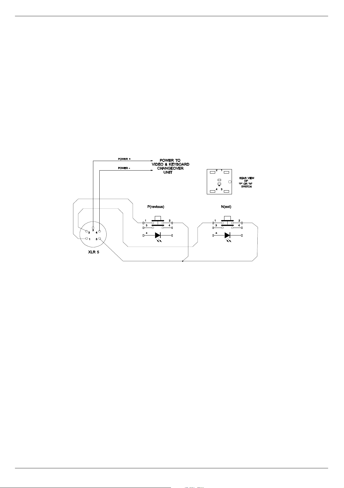
418147 8VLQJ#WKH#9LGHR#DQG#.H\ERDUG#&KDQJH#RYHU#IXQFWLRQ#ZLWK#
6pDQFH#
A single keyboard, mouse and monitor can be used with two computers for main/
back-up vi a th e Séance-box.
The Séance-box is supplied with a cable-kit allowing connections for one keyboard,
one monitor, one mouse and two computers PC1 and PC2.
Using the 5 pin XLR to XLR cable supplied, make the following connection:
CCM KEYS (at the console end) to one of the KEYS-connectors on the rear of
■■■■
the Séance-box.
The second keys connection on Séance is for use with
(see fig 1-20 ).
FIG 1-20. Remote P & N switch wiring detail.
Remote P and N
buttons,
418148 3&5#V\QFKURQLVDWLRQ
Using a Null modem serial interface cable with the appropriate c onnectors for the
computers in use, make the following connection between the two computers.
PC1 COM 1 or 2 to PC2 COM 1 or 2 (selectable in SA M)
■■■■
Two serial port configurations are in common use with 9 way or 25 way 'D-Type' connectors.
The two computers will only “track” each others’ Cue position if the SAM tracking feature has been enabled, see the SAM manual for details.
B-Type Revision B2005-2
Page 27
Connecting the mixer systems 1-19
419 &RQQHFW#PDLQ#IUDPH#IDFLOLWLHV#IURP#PRGXOHV#WR#
IUDPH
See figure below for instructions on how to connect main frame facilities from modules to frame.
)URP#&2006#PRGXOH#+3)/,
HEADPHONES NEXT FRAME
4
5
AUDIO BUS
6
7
DATA BUS
FRAME TO FRA ME
FRAME
SELECTOR
COMMS TO CCM
FIG 1-21. Connecting the main frame facilities from modules to frame.
PSU 1 PSU 2
PSU INDICATOR
)URP#&2006#PRGXOH
FROM PFL NEXT LIGHTS
FRAME - 0V
7R#QH[W#IUDPH
7R #IUDPH#WRS#EDU
AUDIO BUS
4
5
6
7
FRAME TO FRAM E
Revision B2005-2 B-Type
Page 28

1-20 Connecting the mixer systems
41: 6ZLWFKLQJ#21
41:14 6\VWHP#SRZHU0XS#SURFHGXUH
CADAC con s oles are designed to work continuously with two power supply systems
- ‘mai n’ an d ‘b ac k u p’ . The ‘ma in ’ po w er sup ply pai r ( 1 off ‘1 8v ’ un it an d 1 of f 13V/ 48 V
unit ) are designated ‘System 1’. The ‘backup’ power supply pair (1 off ‘18V’ unit and
1 off 13V/48V unit) are designated ‘System 2’.
On each power s upply, tu rn all AC input switches to the ON-position.
Start the ±18 V an d 13V/ 4 8V PSU s (in one PSU syst em) simu lt an eo us ly, by pressing
and holding the START-buttons until you hear the relay click. The CCM will cycle
through its self-test routines and any Master Mute swit ches previously selected will
be set ON, thus protecting external equipment from possible DC pu lses when the
±18V PSUs ar e sta r ted.
Repeat for PSU system 2. If you cannot start the PSUs simultaneously, start the 13V/
48V first. However, do NOT operate the console for long periods without all power
lines on.
41:15 3RZHULQJ0XS#VHTXHQFH#RI#3&V
Always use the following pr ocedure:
Power up console
■■■■
Powe r up Séance box
■■■■
Select PC1 on the CCM and power up the first computer. Wait until the P C1
■■■■
computer has comp leted its boot-up routine, t hen...
Switch to PC2 on the CCM and power-up the second computer and wait until it
■■■■
has completed its boot-up routine.
Once both computers have booted correctly, they should allow the keyboard and
monitor to be switched back and forth without problems.
If the overall cable length for the keyboard and monitor are very long (greater than
5m), it may be necessary to use a keyboard and a monitor booster unit to retain keyboard reliability and a clean monitor display.
41:16 6\VWHP#SRZHU0GRZQ#SURFHGXUH
1. On the CCM, press all Master Mute switches to the ON (down) position.
2. Cl os e down the SA M so ft w are o n ea ch PC , sh ut do w n Wi nd o ws® a nd s wit c h t he
computers off.
3. Switch off the AC mains supply to PSU system 1.
4. Switch off the AC mains supply to PSU system 2.
5. Switch off Séance Box.
.
B-Type Revision B2005-2
Page 29

Central Control Module 7896 2-1
5 &HQWUDO#&RQWURO#0RGXOH#:;<9
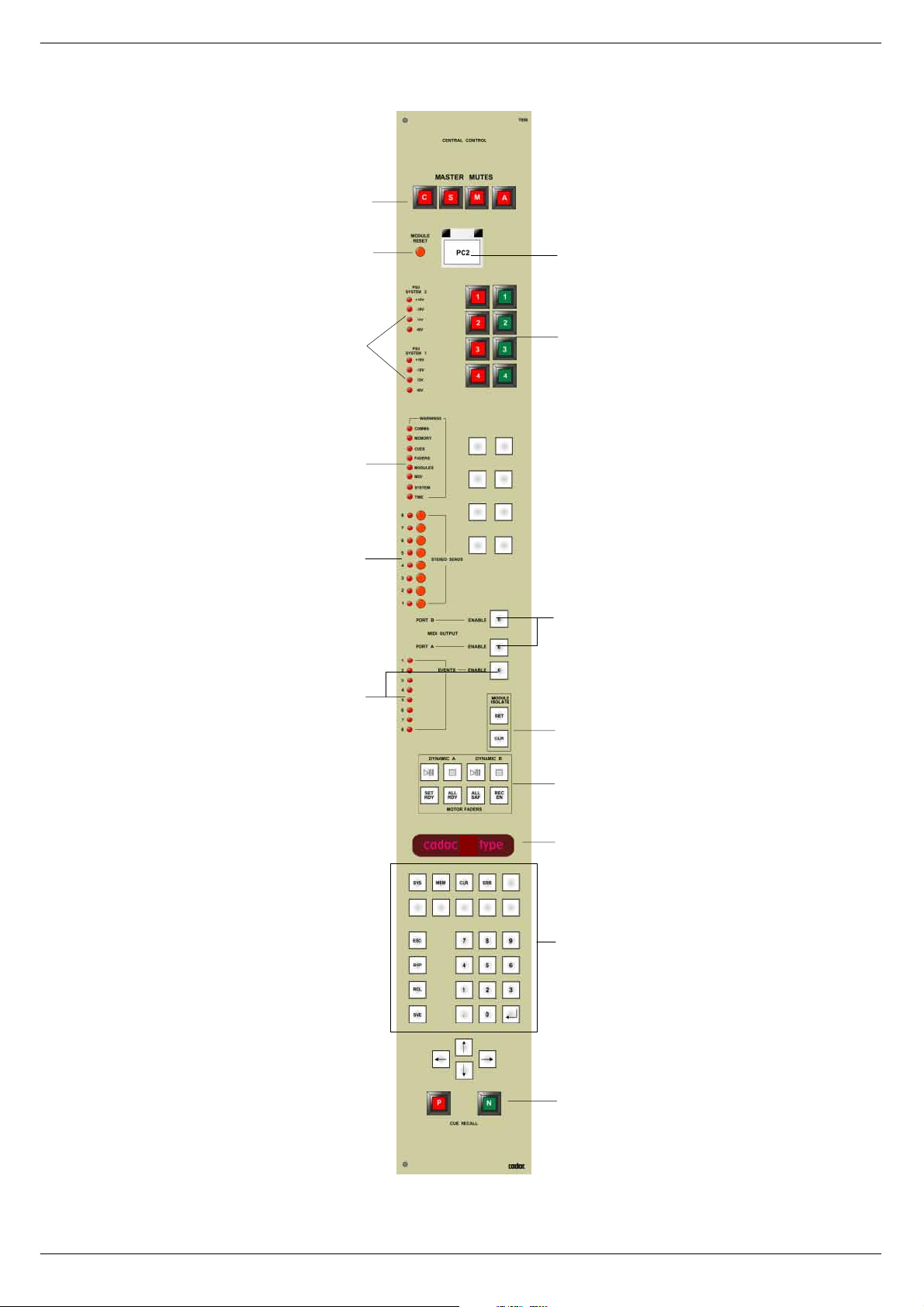
514 &&0#)URQW#3DQHO#VZLWFKHV#DQG#GLVSOD\V
Please re f er t o fi g 2 - 1 o n pag e 2 - 2 f o r the l oc at i on of t he s wi tc he s an d d ispl ays on th e
B-Type CCM fron t panel issue 7896 described on the next page.
D, 0DVWHU#0XWHV
Fo ur separate sw itches to globally mute the channels, subgroups, matrix groups and
aux gr oups. All four switches work independen tly, so that any comb ination o f master
muting may be selected at any time. The switches are intended for manual operation
only, and their condition will not be recorde d with a cue state.
E, 5HVHW
Resets the microprocessors within this module (roughly equivalent to turning the
power off then on again). Pressing reset does not clear the internal memories, maps
etc.
F, 3&5
The Sound Automation Manager software allows two computers to be used with the
syste m , PC1 and PC2. Separate connectors for each computer can be found on the
rear panel of the CCM. Whe n the PC2 switch is pressed, al l data to and from th e
CCM will go to or come from PC2.
G, 368#6\VWHP#4#DQG#368#6\VWHP#5
The J-Type console is designed to be able to use two sets of power supplies simultaneously. These eight LEDs continuously show the status of the tw o sets of ±1 8V,
+13V and 48V power supply units. See 2.2 CCM rear panel connectors for conn ec tion details.
H, *2#0#6723
These are user configured switches for example remote control of cart machines,
tape recorders etc.
I, :DUQLQJ#/('V
These LEDs illuminate when a system function needs to be brought to the o perator ’s
attention. This may be an error condition, a “prompt”, or merely useful system information. The LEDs are labelled with the titles of each part of the automation system
about which the information is available:
1. COMMS Communications with the PC (s), Fast Copper connecti ons.
2. MEMORY Storage space used by the mi croprocess or to hold it ems such
as maps a nd memories
3. CUES Recall of console states from the PC.
4. FADERS Console fader s : channel, master and motorised.
5. MODULES Programmable modules.
6. MIDI Midi i nputs and outputs.
7. SYSTEM General category covering miscellaneous operations within the
CCM.
8. TIME Any timing activity, such as the current date and time.
Revision B2005-2 B-Type
Page 30
2-2 Central Control Module 7896
D
E
G
F
H
I
J
K
M
FIG 1-1. B- Type CCM con tr ol pa ne l.
N
P
B
Q
S
T
B-Type Revision B2005-2
Page 31

Central Control Module 7896 2-3
J, 6WHUHR#VHQGV
Eight momentary switches allowing you to put the associa ted aux group in stereomode. The LED to the left of the switch illuminates when the Aux group is in stereo.
K, 0,',#(QDEOH#VZLWFKHV
ON s witches for MIDI po rts A and B. The switches are momentary and illumi nate
when the functions are enabled.
M, (9(17#/('V#DQG#(1$%/(
The LEDs show the operation of the EVENTS relays. The LEDs will only illuminate
when the ENABLE switch is O N.
N, 0RGXOH#,VRODWH#0#VHW#DQG#FOHDU
These two s witches perform global s witching of ISOLATE function for progr ammabl e
functions such as channels a nd groups, in order to disconnect the con s ole automation system.
P, 0RWRU#)DGHUV
This group of buttons provides a quick and convenient way of setting the console
autom ation system to both re cord and control the mo vement sequences of motor
faders.
The to p left pair control the play /pause an d stop for the firs t dynamic sequence
(dynamic A) in a Cue.
The top right pair control the play/pause and st op for the second dynamic sequence
(dynamic B) in a Cue.
Both dynamics can be run simultaneously in the same cue.
Accidental movement of the motor faders can be prevented by use of the ALL SFE
and ALL RDY keys. In SAFE mode, touching the faders knob will have no impact on
the recorded sequence. In READY mode touching the fader knob will cause the
motor fader logic to toggle between READY and WRITE modes.
Therefore , editing of a reco rded sequence can be performed for as long as the fader
knob is actually touched and the fader remains in the READY mode.
Revision B2005-2 B-Type
Page 32

2-4 Central Control Module 7896
FIG 1-2. Keypad for controlling dynamics.
############
PLA Y/P A USE ( 1)
PLA Y/P A USE (2)
STOP (3, 4)
SET READ Y (5)
ALL READ Y (6)
ALL SAFE (7)
RECORDING ENABLED (8)
Stops the recorded sequence of motor fa der
This mo de allows individual faders to be “toggled”
Plays, pauses or continues a recorded sequence of
motor fader movements a ssociated with dynamic A. If
recording is enabled with the push-button (8), then this
but ton starts either a new recording, or starts an update
of an existing dynamic.
Plays, pauses or continues a recorded sequence of
motor fader movements a ssociated with dynamic B.
movements.
between safe and ready mode by touching the fader
knob.
Sets all motor faders to ready mode.
Sets all motor faders to safe mode.
Prepares the computer for recording of a dynamic
sequence. Pressing button (1) starts the actual
recording.
Q, 0XOWL#IXQFWLRQ#DOSKD0QXPHULF#GLVSOD\
The 16 character alphanumeric display is the communication window between the
operator and the B-Type operating system.
In normal operating conditions the display will show one of the following:
CUE number, or
Current Mem ory numb er, or
“cadac ‘B-Type’ “ if no cue or memory is select ed
The display is also used for system messages via the [err] button and to traverse the
various menus for testing, mapping, etc.
B-Type Revision B2005-2
Page 33

Central Control Module 7896 2-5
S, .H\SD G
The numeric keys [0] to [9] and the decimal point [.] are used to select a particular
cue or m emory number in conjunct ion with one of the fun c tion keys listed below.
Key MeaningFunction
[Sys] SYSTEM Calls up the SYSTEM SETUP menu.
[Mem] MEMORYSelects one of the non-volatile internal memories.
[Clr] CLEAR Clears a selected memory ( i.e. sets everythi ng to
OFF)
[Err] ERROR Writes error message or information to alphanumeric
[Esc]
[Bsp] BACKSPACE Deletes the last number entered.
[Rcl] RECALL Recall a cue or memory.
[Sve] SAVE Store a cue or memory.
[↵] ENTER Selects a menu item, starts or acknowledges
The arrow keys, [←], [→], [↑] and [↓] are us ed to help navigate in the various m enus.
The buttons are back-lit by LEDs, and will illuminate or flash to indicate that they will
perform a useful function if pressed at that time, or that their function has been
selected.
display.
ESCAPE Moves backwards through a menu, or aborts an
operation, can be thought of as a “cancel” button.
operations.
Unlabelled buttons are reserved for use in future software updates.
T, 35(9#DQG#1(;7#EXWWRQV
Use the previous or next button to recall snapshots from the automati on cue list to
the console.
51414 6DIH25HDG\2:ULWH
The following instructions refer to the group of switches on the CCM labelled
“MOTOR FADERS”. See also 3.1.15 RDY LED and 2.1 m) Motor Faders.
To put all motor faders in SAFE mode: Press “ALL SAFE” switch.
To put all motor faders in READY mode: Press “ALL READY” switch.
To put a small number of motor faders in READ Y mode:
a) Press the “SET READY” switch.
b) Touch each fader knob that is to be recorded and make fader movement required.
c) Press the “SET READ Y” switch (to cancel the function).
Revision B2005-2 B-Type
Page 34

2-6 Central Control Module 7896
515 &&0#UHDU#SDQHO#FRQQH FWRUV
Please refer to figure 2-3 for the location of the connecto rs on the B-Type CCM module rear pa ne l de sc ribed below.
D, )DVW#&RSSHU#&RPPXQLFDWLRQV#,22
Two cables provide the “fast copper” data link between the C CM and up to two IBM®
PC or compatible comp uters if these are fitted with a CADAC Fast Copper Communications board 7 514. Otherwise the cables run between the CCM and th e Séance
box, see 1.5.1 Connections - BNC and 1.5.3 Connections - RJ45. Two cables are
normal ly supplied, one f or PC1 and the other for PC2. The connectors are labelled
differently at each end. Make sure that the “CONNECT TO CCM” end is connected
to the CCM! The other ends of the cables are labelled “PC1” and “PC2” respectively.
If the cables are not connected correctly, the communi cations sys tem cannot work.
E,# 368#,QGLFDWRUV
A cable with a 15 way 'D-Type' male connec tor at one end to a 15 way 'D-Type'
fe male connector at the other end is supplied for interconnection between the
Indicators
the console frame.
male connector on the CCM and the
PSU Indicators
fem ale connector on
PSU
The
PSU System 1
will not work un less this connection is made.
and
PSU System 2
LEDs on the CCM front panel (e) in fig 2-1)
F, 5HPRWH#&RQWURO#
The 25 way female 'D-Type' connector labelled RC, is for use with the eight “STOP”
and “START” switches mounted near the top of the front panel (c) in figure 1.11).
Unless special instructio ns are received fro m the customer, this connector is not
D
J
F
I
G
E
FIG 1-3. B-Type CCM rear panel
B-Type Revision B2005-2
H
Page 35

Central Control Module 7896 2-7
wired dir ec tly t o the “STOP” an d “S TART” switches, but term i nates in a 25 way IDCconnector. This allows the user to configure the switch wiring to suit the equipment
they are intended to control. Great care must be taken with the wiring of the
switch(es) to ensure that no short-circuits can occur between any two power supply
units.
+G, 0,',#LQSXWV#DQG#RXWSXWV
Fo ur 5 pin DIN, standard MIDI connectors for the two banks A and B are inclu ded.
The outputs may be connected to any MIDI compatible outboard equipment that
respond s t o pro gram change s , not e on / no te of f and v el oc it y in f orma tio n. See S ou nd
Automation Manager or SAM manual - MIDI, for programming details.
+H, .H\V
See 1.5.8 CCM keys and 1.5.14 Using the Video and Keyboard Change over func-
tion with Séance.
+I, )DGHU#FRPPXQLFDWLRQV
See 1.4.1 Audio Bus / Data Bus Connectio ns, chapte r 1.
+J,# (YHQWV
The 25 way male 'D-Type' connector labelled
tacts to be wired out for external equipment control. The wiring details are shown in
. See SAM manual for details.
Tab le 1
Pin no. Relay no. Function
01 1 normally C LOSED contact
14 1 MO VING contact (wiper)
02 1 norm ally OPEN co nt ac t
15 2 normally C LOSED contact
03 2 MO VING contact (wiper)
16 2 norm ally OPEN co nt ac t
04 3 normally C LOSED contact
17 3 MO VING contact (wiper)
05 3 norm ally OPEN co nt ac t
18 4 normally C LOSED contact
EVENTS
allows the EVENT relay con-
06 4 MO VING contact (wiper)
19 4 norm ally OPEN co nt ac t
07 5 normally C LOSED contact
20 5 MO VING contact (wiper)
08 5 norm ally OPEN co nt ac t
21 6 normally closed contact
09 6 MO VING contact (wiper)
22 6 norm ally OPEN co nt ac t
Revision B2005-2 B-Type
Page 36

2-8 Central Control Module 7896
Pin no. Relay no. Function
10 7 normally C LOSED contact
23 7 MOVING contact (wiper)
11 7 norm ally OPEN co nt ac t
24 8 normally C LOSED contact
12 8 MOVING contact (wiper)
25 8 norm ally OPEN co nt ac t
13 GROUND
516 ,QWHUQDO#PRGXOH#VHWWLQJV
51614 0RGXOH#SRZHU0XS#VWDWH#+,VR21LVR#VHOHFWLRQ,
When the console is first powered up, programmable modules may be set to power
up in ISOLATE mode or in NOT ISOLATE mode. This option is user selectable by
setting links on the motherboard. The factory setting is NOT ISOLATE.
51615 6HOHFWLQJ#RU#FKDQJLQJ#WKH#RSWLRQV
Plac e the CCM module on a fla t surface so that the front panel is f acing you and the
mothe r board is laying on the surface. Locate the three way male molex connector
. This can be found on the mother board near the MIDI B LED25, close to the
CN29
front panel.
The factory setting is NOT ISOLATE, so that the
pins 2 and 3.
To change the POWER-UP STATE to ISOLATE:
Pull off the
programmable jumper
and replace it so that pins 1 and 2 are linked.
517 0RGXOH#OHYHO#VRIWZDUH
When first switched on or after being reset, the CCM display briefly shows the software version number and then performs a check of its internal memory.
Assuming all is found to be well, the display then changes to “cadac B-Type” and the
CCM is ready to be us ed. This is one of the “root” displ ays, and it is always possible
to get back to this point by pressing the
several times). The ot her “root” display possibilities ar e a
[Esc]
memory number
show which will perform a useful function if pressed at this point.
. If this is the case, the appropriate keypad buttons will illuminate to
key (it may be necessary to pre ss
[Esc]
programmable jumper
cue nu m ber
is set to link
or a
The basic operations that can be performed from the “root” display can be summa rized as follows, where button names are shown in
Operation:Type:
Recall cue at the EDIT pointer on PC
Save cue to CURRENT EDIT pointer on PC
Recall cue number nnn.n from PC
Save cue number nnn.n to PC
Recall internal memory n
B-Type Revision B2005-2
Mem n Rcl
Rcl
nnn.n Rcl
nnn.n Sve
Sve
bold
type:-
Page 37

Central Control Module 7896 2-9
Save internal memory n
Clear internal memory n
(where n is a number 0 - 9)
Expl ain a warnin g LED (if applicabl e)
Start the “System setup” menu
The P(revious) and N(ext) buttons can always be used at any time to recall the previous or next cue f rom the PC to the cons ole.
It is not necessary to give a complete four digit cue number, for example, cue
■■■■
25.0 can be entered as just “25”.
When a memory is “Cleared ” all switches are set to be OFF, all fader grou ps to 0
■■■■
and all master displays to be blank.
51714 6DYLQJ#D#&XH
To save a Cue, the CCM must be at one of its “root” displays, (see above for descriptions of the root displays). You can always get back to the root display by pressing
the
Enter the number required for the Cue, us ing the CCM keypad and press the [Sve]
key .
The console status will be saved to that Cue number (in RAM) and the Cue number
will appear in the Cue List Window on the PC.
key one or two times.
[Esc]
Mem n Sve
Mem n Clr
Err
Sys
If the Cue number already exists, the CCM display wil l prompt with “Overwrite
CUE?”. Similarly, the PC will prompt with:
“Cue n exists
Press ENTER to overwrite”
Press [↵] to confirm or
■■■■
pad or the equivalent keys on the PC's keyboard.
If you press the [Sve] key with no number, the system will try to save the console status to the Cue at the current pointer on the PC and will respond with the same
prompts as set ou t above. This does
Window, (this would be the case if you were starting to program a new Show). When
the Cue List Window is empty, [Sve] create s a Cue and gives it the number 1.0.
An invalid Cue number, (outside the range 0.01 to 9999.99), will result in the error
prompt “Bad cue number”, on the CCM display, and “Bad cue number from CCM”, on
the PC monitor. Press [↵] or
51715 5HFDOOLQJ#D#&XH
To recall a Cue, the CCM must be at one of its “root” displays, (see above for descriptions of the root displays). You can always get back to the root display by pressing
the
Enter the number required for the Cue, us ing the CCM keypad and press the [Rcl]
key .
key one or two times.
[Esc]
to cancel. You may use the keys on the CCM key-
[Esc]
apply if there are no Cues in the Cue List
not
to continue.
[Esc]
If the Cue number exists, the console status will be updated to the data contained in
that Cue number (the last time it was saved).
If the Cue number does not exist, the CCM display will show the error prompt, “nonexistent cue” and the PC will show the error as “Cue n does not exist”. Press [↵] or
to continue.
[Esc]
Revision B2005-2 B-Type
Page 38

2-10 Central Control Module 7896
51716 6DYLQJ#D#FRQVROH#VWDWH#WR#DQ#LQWHUQDO#PHPRU\
To save a console state to an internal memory, the CCM must be at one of its “root”
displ a ys , (see ab o v e fo r de sc ript io ns of t he ro ot d is pla y s) . You can al w a y s ge t ba ck to
the root display by pr essing th e
Press the [Mem] key.
■■■■
Enter the number for the internal memory.
■■■■
Press the [Sve] key.
■■■■
The console state is saved to the internal memory.
key several times.
[Esc]
51717 5 HFDOOLQJ#D#FRQVROH#VWDWH#IURP#WKH#LQWHU QDO#PHPRU\
To recall a console state from an internal memory, the CCM must be at one of its
“root” displays, (s ee above for descriptions of the root displays). You can always get
back to the root display by pressing the
Press the [Mem] key.
■■■■
Ente r the number of the internal memory required.
■■■■
Press the [Rcl] key.
■■■■
key one or two ti mes.
[Esc]
The current console state is replaced by the state stored in the internal memory.
518 7KH#6\VWHP#6HWXS#PHQX
This is a set of menus which are navigated by using the
and [↓], with selections being made by pressing
.
[Esc]
Menu items appear in the display with either a question mark (?) or pair of
arrows(⇑⇓) on the right. The arrows indicate that this is the title of the current menu
and that the user should press the up and down arrow keys to make a selection. The
question mark means that this is a selectable item, (press [↵] to select). The menu
wraps around, so if you move down from “User setup?” you get to “System setup
“again. In order to speed up the action of traversing these menus, they
⇑⇓
reset themselves to the title position each time that they are used. For example; if
“Map Faders?” was selected the last time the [Sys] k ey was pr essed, then the “Map
Faders?” option will appear again, the next time the [Sys] is pressed (provided that
the CC M has not bee n reset).
Press the [Sys] key.
The first menu contains the follo wing items:
#
System setup
Map Faders ?
Test Routines ?
User setup ?
The Map Faders, options will immediately perform that operation, whereas the Test
System , User Setup, M IDI recorder and MIDI mu ting selectio ns lead on to other
menus:
Title
⇑⇓
Perform fader mapping.
Move to the system test menu
Move to the user setup menu
and
up
down
], and cancelled by pressing
enter [↵
arrow keys [↑]
do not
System Test
Inc All Faders ?
Show MFdr data ?
Test Motor Fdrs ?
Test Key s ?
Test M IDI ?
Test Events ?
Test Fdr Comms ?
Show Time ?
Show Date ?
View Error Log ?
Clear Error Log ?
B-Type Revision B2005-2
Title
⇑⇓
Test routines for channel and group faders
Read information from the motor f aders
Check mechanical operation of motor faders
Check keys indicate on the display
Send programme c hanges to MIDI-connections
Check relays and indication of events
Check communications busses
Show real-time clock
Show real-time cl ock and da te
Look through the last recorded errors
Clear the error log
Page 39

Central Control Module 7896 2-11
.
.. and...
User Setup
Enable options ?
Set P&N Keys ?
Midi PC Filter ?
MIDI All off ?
Show Map Add r e ss es?
Faders GrpL nk ?
Twi n Ma sters ?
Event Duration ?
Revert Mode ?
Revert Time ?
PC Comms Error ?
Global Level ?
51814 0DSSLQJ
Before the console automation can be used, all faders and programmable modules
must be mapped. Each Map is stored in non-volatile memory within the CCM. Mapping operations should only need to be performed if the layout of the modules within
the frame have been changed. A new console is always mapped by CADAC before it
leaves th e factory.
Each module po sition in a frame is i dentified by a unique n umber (the address). This
number is set by a combinati on of a small PCB fixed to the f rame beneath each module and the frame number switch at the back of a frame. As each fader i s connecte d
to a module, it too can be given a unique address.
Title
⇑⇓
Set 2n d Function on or off
Select how the P and N buttons are illuminated.
Program change filter on/off
All no tes off mes s ages on/off
Shows Module/Fader addr.while mapping on/off
Configure channel faders relative to master
Set number of twin masters
Set duration of event (i.e. length of pulse required
for control of external equipm ent)
Set motorized faders to revert to original position
when moved
Set the time it takes for a motorized fader to revert
to its original position
51815 )DGHU#0DSSLQJ
Ensure all faders are
the sys tem setup menu and press [↵].
The display changes to “Wait......”, as the CCM checks for faders in the console.
When the ch ec k is c omp le t e, t he di splay change s t o “Faders: 0". The CCM i s no w
ready for mapping to begin.
Press the
usually the left-most fader in the frame. The
ext inguish - the CCM display should now read “Faders: 1 “. Now press the
button of the channel fader you wish to be
along - the CCM display should now read “Faders: 2 “. Continue setting each fader
into MUTE until all the c hannel f aders ha ve been mapped.
Continue pressing the Mute buttons for the MASTER faders. The number shown in
the CCM display shows the
MASTE R bus controlled by each master fader is set by switches on the fader PCB
and is
not
If y ou are satisfied that the console faders have been mapp ed correctly, press [↵] to
stop ma ppin g and sto re th e new map, ot he rw is e pres s
button of the channel fader that you wish t o be
MUTE
affected by fader mapping.
NOT ISOLATED
number of faders in the console. Note that the DC
total
and
NOT MUTED
MUTE
“channel fader 2"
. Select “Map Faders?” from
“chann el fad er 1"
led will illuminate briefly then
, usual ly the next one
to cancel this operation.
[Esc]
MUTE
,
Revision B2005-2 B-Type
Page 40

2-12 Central Control Module 7896
51816 7HVW #5RXWLQHV
See below for options .
D, 6\VWHP#WHVW#²#7HVW#IDGHUV#4
In the system menu, select “
The display shows “
Press [↵], followed by the Down Arrow button, until the display shows “
■■■■
”
Faders?
Press [↵]. The display changes to “
■■■■
The group number display on each of the channel s faders increment s from 0 to C,
before returning to zero.
At the same time on the channel, the following automated switches cycle:
At the end of ea ch cy cle:
Test Routines?”
Test Routines?”.
MIC 1 ON
MIC 2 ON
PAN
LP FILTER
HP FILTER
EQ 1 IN
EQ 2 IN
INS
VCA MUTE
NEXT TIME
AUX
NEXT TIME
VCA MUTE & AUX
using the Up or Down ar row butto n.
Testing Faders
”.
Inc All
Meanwhile the groups automated switches c ycle:
INS A
INS B
MAT PRE
SUB INS
At the end of each cycle the DC Master MUTE turns ON and OFF.
Press
to return to the system menu or Down arrow to perform next test.
[Esc]
E, 6KRZ#0)GU#'DWD
In the system menu, select “
The display shows “
Press [↵], followed by the Down Arrow button, until the display shows “
■■■■
”
ers 2?
These tests are for the operati on of Motor faders o nly
the console, skip these tests and go to 2.3.11 “
Press [↵]. Check that all Motor faders are responding and that their positions are
■■■■
correc tl y displayed.
Using the Left and Right arrow keys, select the fader to test. (Press [↵] to go
■■■■
directly to th e channel faders.)
The display shows: “Group 1:0000 00”
Test Routines?”
Test Routines?”.
using the Up or Down ar row butto n.
. If there are no Motor faders in
Test keys
”.
Test fad-
The left and right arrow keys may be used to select each fader in turn, group 1
through 16, then channel 1 upwards. The numbers displayed after the colon represent the raw fader data. If you encounter difficulties, please contact CADAC.
B-Type Revision B2005-2
Page 41

Central Control Module 7896 2-13
F, 7H V W#PRWRU#IDGHUV
In the system menu, select “
The display shows “
Press [↵], followed by the Down Arrow button, until the display shows “
■■■■
”
Fders?
Press [↵]. The Motor faders should now move up and down (they move slower at
■■■■
the bo ttom end). Check that all Motor fad ers are moving at the same rate an d that
they run smoothly.
■■■■
Press
to return to the system menu or Down arrow to perform next test.
[Esc]
Test Routines?”
Test Routines?”.
using the Up or Down arrow button.
T est Motor
G, 7H V W#NH\V
In the system menu, select “
The display shows “
Press [↵], followed by the Down Arrow button, until the display shows “
■■■■
”
Keys?
Press [↵]. The display shows
■■■■
Press ea ch of th e b u tto ns , inc ludi ng th e P & N but t on s (b ut not th e Esc b u tto n) in
■■■■
turn, ensuring that the display shows what button has been pressed.
Check also the external P & N.
■■■■
Press
to return to the system menu.
[Esc]
Test Routines?”
Test Routines?”.
“Button = ...”
using the Up or Down arrow button.
Test
H, 7H V W#0,',
In the system menu, select “
The display shows “
Test Routines?”.
Test Routines?”
using the Up or Down arrow button.
Press [↵], followed by the Down Arrow button, until the display shows “
■■■■
”
MIDI?
Press [↵]. This test outputs programme change to the MIDI-connections on the
■■■■
back of the CCM, indicating channel changes in ascending order for MIDI A (1-16)
and in descending order for MIDI B (16-1).
To perform a cable test and to ensure MIDI-cables have not been crossed over, a
cable can be connected between MIDI out and MIDI in. This will cause a flashing “A”
if connected between MIDI A output and MIDI A input and a flashing “B” if connected
between MIDI B output and MID I B input.
Press [Esc] to return to the system menu or Down arrow to perform next test.
Test
I, 7H V W#HYHQWV
In the system menu, select “
The display shows “
Press [↵], followed by the Down Arrow button, until the display shows “
■■■■
”
Events?
Press [↵]. Make sure that the Events enable switch is on. The LED’s indicating
■■■■
events should now come on and off in sequence. Turning the enable sw itch off
should cause all the LED’s to extinguish.
Press [Esc] to return to the system menu or Down arrow to perform next test.
■■■■
Test Routines?”
Test Routines?”.
using the Up or Down arrow button.
Test
J, 7H V W#)GU#&RPPV
In the system menu, select “
The display shows “
Test Routines?”.
Test Routines?”
using the Up or Down arrow button.
Press [↵], followed by the Down Arrow button, until the display shows “
■■■■
Press [
”
]. The display sho ws “Comms busses OK” for a few seconds before
↵↵↵↵
Test Comms?”
Comms?
■■■■
returning to “
Revision B2005-2 B-Type
Test
Page 42

2-14 Central Control Module 7896
If there is a f ault, a fault code is display ed indicating the type of fault.
■■■■
This test automatically returns to “Test comms?”.
K, 6KRZ#7LPH
In the system menu, select “
The display shows “
Press [↵], followed by the Down Arrow button, until the display shows “
■■■■
”
Time?
Press [↵]. The display shows the time as set in the PC.
■■■■
Press [Esc] to return to the system menu or Down arrow to perform next test.
Test Routines?”
Test Routines?”.
using the Up or Down ar row butto n.
Show
L, 6KRZ#'DWH
In the system menu, select “
The display shows “
Press [↵], followed by the Down Arrow button, until the display shows “
■■■■
”
Date?
Press [↵]. The display shows the date as set in the PC.
■■■■
Press [Esc] to return to the system menu or Down arrow to perform next test.
The Time/Date do not increment when power is removed from the console.
NOTE:
They rely upon SA M updating them when communicat ions are fir st estab lished.
Test Routines?”
Test Routines?”.
using the Up or Down ar row butto n.
Show
M, 9LHZ#(U U RU#/RJ
In the system menu, select “
The display shows “
Test Routines?”.
Test Routines?”
using the Up or Down ar row butto n.
Press [↵], followed by the Down Arrow button, until the display shows “
■■■■
”
Log?
Press [↵]. The display lists the time and date of errors/events.
■■■■
Select
■■■■
■■■■
■■■■
NOTE:
are not in themselves errors. Examples are Time/Date reset
the display a re not errors.
Press [Esc] to return to the system menu.
Time/Date
Press the Right arrow key to display the type of error.
Press the Left arrow key to get back to the list of time/date.
Some mes s ages are included in the erro r log for debugging purposes that
with the arrow keys.
or
Host is Sé ance
N, &OHDU#(UURU#/RJ
In the system menu, select “
The display shows “
Press [↵], followed by the Down Arrow button, until the display shows “
■■■■
Press [
”
]. The log is cleared and the event is entered in the Error log.
↵↵↵↵
Error Log?
■■■■
This test automatically returns to the system menu.
Test System?”
Test System?”.
using the Up or Do wn arrow button.
View Error
on
Clear
B-Type Revision B2005-2
Page 43

Central Control Module 7896 2-15
51817 8VHU#6HWXS
See below for options .
D, (QDEOH#RSWLRQV
The
you to override the setting of one or both MIDI ports and/or the Events for one Cue
only.
When “2nd Function on” is selected, the software will interpret a “double key press”
as an instruction to reverse the condition of the Enable sw itch for one Cue on ly.
Example: MIDI ports A, B and Events enabled, but you wish to disable MIDI port B
for one Cue only.
Press MIDI port B Enable switch two times in quick succession, (rather like “double
clicking” with the mouse). The LED in the MIDI port B Enable sw itch will now “fla sh”.
Recall the required Cue. MIDI information from port A and the Events will be transmitted, but no data will be transmitted from MIDI port B. The LED in the MIDI port B
Enable switch will no w return to fully “on”. If another Cue is now recalled, then data
will be transmitted on MIDI ports A, B and the Events.
switches on the CCM have a “second function” capability. This allows
Enable
6HOHFWLQJ#WKH#5QG#)XQFWLRQ#RQ#RU#RII
Press the [Sys] key to use the
■■■■
Press the [↑] or [↓] cursor keys until
■■■■
Select the sub-menu by pressing [↵].
■■■■
The CCM display will respond with
Press the [↑] or [↓] cursor keys again until
■■■■
display.
Press [↵], to select the option.
■■■■
System Setup
“User Setup
menu.
“User Setup
⇑⇓“.
“Enable keys?”
?” appears in the CCM display.
appears in the CCM
The CCM display will show either:
³5QG#)XQFWLRQ#RQ´
RU
³5QG#)XQFWLRQ#RII´
Press the [↵] ke y to t ogg l e bet w een on or o ff . Whe n “ 2 nd Func ti on ” is set as r e qu ire d,
press
to return to one of the “root” displays.
[Esc]
E, 6HW#3#)#1#NH\V
The illumination of the P(revious) and N(ext) switches can be set for the following
conditions:
³2Q´#DOO#WKH#WLPH#+OLW,1
³2II´#DOO#WKH#WLPH#+XQOLW,1
&RPH#³RQ´#IRU#VKRUW#WLPH#ZKHQ#WKH#VZLWFK#LV#SUHVVHG/#DQG#
WKHQ#JR#³RII´#+IODVK,1
Press the [Sys] key to use the
■■■■
Press the [↑] or [↓] cursor keys until
■■■■
Select the sub-menu by pressing [↵].
■■■■
The CCM display will respond with
System Setup
menu.
“User Setup
?” appears in the CCM display.
³8VHU#6HWXS
Revision B2005-2 B-Type
####⇑⇓³1
Page 44

2-16 Central Control Module 7896
Press the [↑] or [↓] cursor keys again until “P & N keys?” appears in the CCM dis-
■■■■
play .
Press [↵], to select the option.
■■■■
The CCM display will show either:
³3#)#1#NH\V=#OLW´
RU
³3#)#1#NH\V=#XQOLW´
RU
³3#)#1#NH\V=#IODVK´
Press the [↵] key to cycle through three options.
■■■■
When the required option is set, press
to return to one of the “root” displays.
[Esc]
F, 0,',#3&0ILOWHU
The MIDI Progr am Change fil ter can be selected on or off.
When the MIDI Program Change filter is “on”, only the first Program Change message for a specific MIDI Channel is sen t. Any ide ntical PC messages to the same
channel are fil tered out.
Alternatively, when th e MIDI Program Change filter is “off”,
sent, whenever they appear in the data.
The reason for including this option, is that some types of MIDI controlle d equipment
“close do wn” for a short time when a PC mes sag e i s rece ived, caus in g a br ief l oss of
the au dio signal. It is therefor e unnecessary and undesirable to repeat the same PC
number.
Press the [Sys] key to use the System Setup menu.
■■■■
Press the [↑] or [↓] cursor keys until
■■■■
Select the sub-menu by pressing [↵].
■■■■
The CCM display will respond with
³8VHU#6HWXS
Press the [↑] or [↓] cursor keys again until
■■■■
display.
Press [↵], to select the option.
■■■■
####⇑⇓³1
“User Setup?”
“MIDI PC filter?”
PC messages are
all
appears in the CCM display.
appear s in the CCM
The CCM display will show:
³3&#ILOWHU#RQ´
Press [↵], to toggle between on and off.
■■■■
When the required option is set, press
#RU#³3&#ILOWHU#RII´
to return to one of the “root” displays.
[Esc]
G, 0,',#$OO#1RWHV#2II
When a
Note On
ously until a
If a Cue sequence is terminated before the
will carry on “sounding”, and may cause a problem. The MIDI
designed to deal with this problem.
If you select “MIDI All Notes Off: Yes”, then an
channel of a partic ular port when the relevant MIDI O/P Port Enable switch es is set
“off”.
Press the [Sys] key to use the
■■■■
Press the [↑] or [↓] cursor keys until
■■■■
B-Type Revision B2005-2
message is sent to MIDI equipment, the note will “play” continu-
Note Off
message is received.
System Setup
“User Setup?”
Note Off
All Notes Off
menu.
message is sent, then the note
All Notes off
message is sen t on ea ch
appears in the CCM display.
option is
Page 45

Central Control Module 7896 2-17
Select the sub-menu by pressing [↵].
■■■■
The CCM display will respond with
Press the [↑] or [↓] cursor keys again until “MIDI All Notes Off?” appears in the
■■■■
CCM display.
Press [↵], to select the option.
■■■■
“User Setup
⇑⇓“
.
The CCM display will show:
Press [↵], to toggle between yes and no.
■■■■
When the required option is set, press
“All Notes Off no “
or
“All Notes Off yes”
to return to one of the “root” displays.
[Esc]
H, 6KRZ#PDS#DGGUHVV
The default setting of
the number of faders/modules being mapped. In addition, if
the display also shows the physical address of the module or the fader as a hexadecimal representation when mapping.
When the required option is set, press [Esc] to return to one of the “root” displays.
“Show Map Addrs”
is Off. In this state, the CCM display shows
“Show Map Addrs”
is On,
*URXS#/LQN#0RGH
If motorized VCA channel faders are used in conjunction with motorized DC master
faders, then the system can be configured so that a single DC master fader can
mov e al l th e cha nnel f a de rs in th e con so le . More sp eci f ic ally, if a group of f ad ers controlling the orchestra “ m ix” are assigned to a particular DC master fa der then logically , they will all move relative to the master controlling element. In this situation
“A UX fro m V CA ” does n ot h a v e the s ame me an in g a s a no n-mo to r fader s yst em . Th e
mode of operation where the channel faders “move” relative to the DC master faders
is called Group-Link mode.
In many live sound applications, a motor fader system needs to have a second mode
of operation in order to make the system as flexible as possible. When Group-Link is
off, channel fader movements are “disconnected” from the DC master fader movements, althou gh lev el change s are still achieved using VCA control. This allows the
motor fader system to behave more l ike a manual fader system.
*URXS0/LQN#2))
The channel fader motor system is “disconnected” from the DC master bus motor
system. In this mode, DC master faders
When AUX VCA
The post f a der aux il i ary send sig na l wi ll be un der the con t rol of the ch an ne l f ad er
■■■■
only.
The DC master fader will only control the main VCA on the channel.
■■■■
When the Aux VCA switch is selected on a fader, then the appropriate DC mas-
■■■■
ter fader will control the
The main and the auxiliary signal levels will follow the master cont rol element .
■■■■
In this mode, the motor fader system will behave in the same way as a non-motor
fader VCA system, except that channel and DC master faders may be programmed
fo r “snapshot ” position changes even if the appropriate master is at
selected on a channel fader:
is not
VCA and t he
Main
“move” chan ne l fader s.
will not
VCA on th e channel.
Aux
∞
.
*URXS0/LQN#21
In Group-Link mode, the DC ma ster faders can “mo ve” channel faders. AUX from
VCA does not have the same m eaning as in a non-motor fader system.
When AUX VCA
selected on a channel fader:
is not
Revision B2005-2 B-Type
Page 46

2-18 Central Control Module 7896
The ch annel fader MUTE button only effects the
■■■■
nel
When the AUX VCA switch is selecte d on a fader:
■■■■
The channel fader MUTE button affects the main
■■■■
send signals from the channel.
Channel faders selected to a DC master fader will always “fol low” the DC master
Fader. Channel and DC master faders may be programmed for “Snapshot” position
change s an d can be used in dy na m ic cues.
audio out pu t from a cha n-
main
the post fader auxiliary
and
0RWRU#IDGHU#EHKDYLRXU#ZKHQ#VZLWFKLQJ#EHWZHHQ#PRGHV
When entering or leaving
it is assigned to a VCA group ot her than 0, and the relevant DC master i s set at a
position other than 0dB
Group-Link
mode, the channel fader position
will change
I, 7ZLQ#PDVWHUV
This option is used in the event that an external master fader box is connected to the
console. When “twins” are enabled, moving a Master Fader will cause its twin to
move in the same way. This allows a modicum of remote control.
Using the arrow keys, select
■■■■
[↵].
Select the number of Twin masters in the box, by pressing [↵] until the number
■■■■
appea rs on the CCM display.
“Twin masters”
in the menu
“User Setup”
and press
if
Press
to go back to the
[Esc]
“User Setup”
menu.
J, (YHQW#GXUDWLRQ
The Events-function allows control of external equipment, such as CD-players, tapedecks, effects-boxes, etc. via 8 relays within the CCM. These relays can be in one of
three st ate s :
ON = always on
OFF = always off
PULSE = toggles between on and off
PULSE duration can be set to a value (1-25) as required to control the external
equipment.
Using t h e ar ro w k eys se le ct
■■■■
[↵].
The display shows “Event Dur: “
■■■■
Press [↵] again until PULSE is set to a value be tween 1-2 5 (25 = 3 sec).
■■■■
Press [Esc] to go back to the
“Event Duration”
“User Setup”
menu.
in the me nu
“User Setup”
and pres s
K, 5HYHUW#0RGH
Rev e rt Mo de al lo ws mot o r fa de r s to r e turn t o th eir or igin al po si tio ns if t he y have bee n
manually put in their position. The time they take to do this may be programmed (see
below) and the operati ng circums tances which prompt them to “revert” may be set
as:
OFF Function Off
RECORD Function enabled when rec ording a dynamic
REC/PLAY Function enabled when recording or playing back a
dynamic
ALWAYS Function always enabled
The option ALW AYS is primarily intended for test purposes.
B-Type Revision B2005-2
Page 47

Central Control Module 7896 2-19
L, 5HYHU W#7LPH
The time it will take for a motorized fader to resume its original position is set using
the option
cal button and then pre ss
Revert Time
in the User Setup in the CCM. Enter a value with the numeri-
Enter.
M, 3&#&RPPV#(UU R U
If the B-Type is used without a PC, this function disables the “ERR” button and prevents it from flashing because of missing Comms. There are two modes; “Hard” and
“Soft ”. Hard mode will cause the “ERR” button to f lash when Comms are missing
(when a PC and a CCM are used) and Soft mode will cause the “ERR” button to
flash in the e vent of any other error than missing Comms.
Using the arrow keys, s elect
■■■■
press Enter.
The display shows “
Press Enter to toggle between Hard and Soft.
■■■■
Press Esc.
■■■■
PC Error: “
“PC Comms Error?”
N, *OREDO#OHYHO
This function is not yet implemented.
from the User Setup menu and
Revision B2005-2 B-Type
Page 48

2-20 Central Control Module 7896
B-Type Revision B2005-2
Page 49

Input Channel module 7718 3-1
6 ,QSXW#&KDQQHO#PRGXOH#::4;
The in put channel has a single input capable of accepti ng a wide range of input
sources. The input signal may be routed to any or all of the 28 groups available on
the system. A separate Direct Output can be provided.
The equalize r and LP/HP filters can be switched in and ou t separately. Each EQ section has controls for ±18dB cut and boost, variable frequency and Q. There are four
EQ bands.
The normal PFL and MUTE switches are situated near the fader section of the module, above and below the ‘DC Group” display.
Fo llowing pages describe the input channel module 77 18 in detail.
Revision B2005-2 B-Type
Page 50

3-2 Input Channel module 7718
614 ,QSXW#&KDQQHO#PRGXOH#::4;#0#IURQW#SDQHO
3.1.2 -20dB Pa d
3.1.3 Phase Change
3.1.1 Input Gai n
3.1.4 48V Phantom Power
3.1.5 OSC/PNG Select
3.1.6 Input Amplifier PFL
3.1.7 Auxiliary sends
B-Type Revision B2005-2
Page 51

Input Channel module 7718 3-3
61414 ,QSXW#*DLQ
The input gain is continuously variable from +10dB (minimum) to +60dB. Combined
with the use of the -20dB pad, this allows the use of a wide range of input devices
including ribbon, dynamic, electret and capacitor microphones; CD-pla yers, Mini
Disc and Reel to Reel tape machines etc.
61415 053G%#3DG#6ZLWFK
The ‘-20’ switch puts a 20dB attenuation pad in series with the I/P signal.
Use the -20dB pad when the input is at line lev el, or to r educe the overall gain b y 20
dB.
61416 3KDVH#&KDQJH#‘
Use the ‘Ø’ switch to change the phase of the input signal.
When this function is selected, the incoming signal has its phase changed by 180°.
61417 7;9#3KDQWRP#3RZHU
The 48V switch connects phantom power to the I/P line. This can be used to supply
power to most makes of capacitor and electret microphones.
61418 26&231*#%XV#6HOHFW
The ‘~’ switch connects the OSC/PNG bus to the input amplifier.
You may sel ect a sine wa ve tone for line-up purposes, or pink noise for loudspeaker
calibration (selectable on OSC/PNG/COMMS module).
61419 ,QSXW#$PSOLILHU#3)/
An extra PFL switch for monitoring the input amplifier only. Very useful when fault
find ing; e.g . if signa l is present at input amplifier, but not a t the main PFL, then the
fa ult will be in a circ uit between the input ampli fier and the main VCA.
6141: $ X[LOLDU\#6HQGV
There are 28 mono Auxiliary sends or 14 stereo sends. Each send can be switched
on or off and pre or post fader independently. LEDs to the left-hand side of each
swit ch i llum in at e wh en a switch i s se le cted . Wh en th e L E Ds a re no t il l umina t ed , eac h
secti on is connected post fader and OFF.
Mono mode The dual-concentric potentiometers in each section provide indi-
vidual level controls for 28 mono auxiliary se nds.
Stereo mode The dual-concentric potentiometers in each section change
funct ion. The upper potentiometer is the auxiliary send level
control and the lower potentiomete r becomes the balance
control.
Stereo mode selection is a ‘global mode’ controlled from the
CCM (see 2 Central Control Module 7896).
E.g. If Auxiliary 1 is selected ‘STEREO’ on the CCM, the “SET” LED in the AUX1
secti on on all input channels will illuminate and all AUX1 secti ons are stereo sends.
Revision B2005-2 B-Type
Page 52

3-4 Input Channel module 7718
3.1.8 Equalizer
3,1,10 EQ IN/OUT Switch
(programmable)
6141; (TXDOL]HU
There are fou r EQ sections with variable controls f or ±18dB cu t/boost, frequency,
and Q.
The HF frequency control allows you to sweep throu gh the range 1.5kHz to 15kHz.
MF2 sweeps through 400Hz to 4kHz.
MF1 sweeps t hrough 60Hz to 600Hz.
And the LF frequency contr ol sweeps through the range 20Hz to 20 0Hz.
The Q con t rol v arie s th e ba nd wid t h of the E Q se ct io n in th e r a ng e Q= 1 to Q =3. A l ow
Q value gives a wide bandwidth. This means that a relatively large range of frequencies (either side of the centre frequency) have the cut/boost applied. A the Q value is
increased, the bandwidth is reduced, so that a very much smaller range of frequencies have c ut/boost applied.
3.1.9 LP/HP Filter
6141< /32+3#)LOWHU#+SURJUDPPDEOH#LQ2RXW#VZLWFKHV,
The Low Pass f ilter has an in/out s witch with a variable frequency control from
1.2kHz t o 35 kH z .
The High Pass filter has an in/out switch with a variable frequency control 14Hz to
400Hz.
614143 (4#,12287#6ZLWFK#+SURJUDPPDEOH,
The “EQ IN” switch (in the HP/LP section) simply switches the EQ in or out of circuit.
B-Type Revision B2005-2
Page 53

Input Channel module 7718 3-5
3.1.11 Insert (programmable)
3.1.12 Grand Master 2
3.1.13 Grou p +/-
3.1.14 VCA Mute (programmable)
3,1,15 RDY LED
3.1.16 ISOLATE
3.1.20 20 Segment LED Meter
3.1.17 PFL Switch
3.1.18 DC Group Display (programmable)
3.1.19 MUTE switch
3.1.21 Channel Fader
3.1.22 Fader Open LED
614144 ,16>HUW@#+SURJUDPPDEOH,
All input channels have a Send and Return break-jack facility placed after the equalizer. Th is is to allow the channel signal to be se nt out to, and returned from an external pr ocessing unit. A relay is used to s witch the insert function IN and OUT. Whe n
INSERT is not selected, the signal is passed directly from the EQ section to the
fader.
Select INS to divert the channel audio signal to an external device and have the processed signal inserted into the signal path.
Revision B2005-2 B-Type
Page 54

3-6 Input Channel module 7718
614145 *UDQG#0DVWHU#5
The “GM2 CTRL” LED illuminates when input channels have been gl obally se t to be
controlled by a single master fader. “Grand Master 2 Control” is selected on the
CCM under the “USER OPTIONS” menu. See Chapter 2.
614146 *URXS#.20
Press the Group + switch to increment the DC Master Group number and Group switch to decr ement the DC Master Group number. The DC G roup number is displayed on the seven segment display to the ri ght of the switches.
614147 9&$#0XWH#+SURJUDPPDEOH,
When VC A Mu t e is O N a nd A UX V CA is O N th en an y si gn al co ntr ol l ed b y t he f ad er is
muted, and no signal passes through the channel. VCA Mute is a progr ammabl e
function.
614148 5'<#/('
The RDY LE is associated with the motor fader functions SAFE, READY and WRITE.
RDY LED ModeSystem response
Off SAFE No dynamic data will be sent from the fader to the PC,
but the fader will respond to data from the PC.
On READYThe fader is ready to send data to the PC, but no data
will be sent until WRITE mode is invoked by touching the
fa der knob.
Flas h WRITEAs soon as the fader knob is touched, dynamic data is
sent to the PC. The fader knob will not respond to data
sent from the PC until the f ader knob is released.
Full details on using the SAFE/READY/WRITE modes are shown in the SAM (Sound
Automation Ma nager) user manual.
614149 ,62>ODWH@
When ISO is ON, the module is effecti vely disconnected from the computer system.
It cannot send commands to the comp uter, or receive command fro m the computer.
The mo dule responds as though it were a manual unit.
61414: 3)/#6ZLWFK#+0DLQ#3)/,
A PFL switch is included in each channel to allow the operator to instantaneously
monitor the audio signal in the chan nel, pre fader .
61414; ¶'&#*URXS#'LVSOD\#+SURJUDPPDEOH,
A seven segment display shows which DC Group M aster the channel is currently
selected to.
B-Type Revision B2005-2
Page 55

Input Channel module 7718 3-7
61414< 087(#6ZLWFK
A Mute switch is included on each channel to allow the operator to instant aneously
switch off the audio with put disturbing the fader balance.
The MUTE switch also has a secondary function when used in conjunction with the
CHECK switch (located on the OSC/PFL Module). If a chan nel is mut ed (MUTE
switch ON) and the CHECK switch is pressed, the muted channel is unmuted, but all
other channels are fo rced into M UTE. This allows the originally muted channe l to
have a ‘SOLO’ function.
614153 53#6HJPHQW#/('#0HWHU
The 20 s eg men t LED me te r co nt in uo usl y m on itor s the si gn al l ev e l in the ch an ne l, p re
fa der. The meter scale is printed to the left of the LED column.
614154 &KDQQHO#)DGHU
A standard audio taper fader with a travel of 100mm controls the signal le vel through
the channel via a VC A circuit on the main audio sub board.
614155 )DGHU#2SHQ#/('
This LED illuminates as soon a s the fader moves away from infinity unless the following cond iti on s ap ply:
The Fader has its local VCA MUT E set ON.
■■■■
The fader is being controlled by a DC Master fader set fully OFF (at infinity)
■■■■
The fader is being controlled by a DC Master fader with its local VCA MUTE set
■■■■
ON.
Revision B2005-2 B-Type
Page 56

3-8 Input Channel module 7718
615 ,QSXW#&KDQQHO#PRGXOH#::4;#0#UHDU#SDQHO
Standard 0.25” (6.35mm) 3-pole
jack socke t, providing a con tinu-
ous electronically balanced output.
Electronically balanced input on
an XLR 3-31 connector for microphone or line level sources.
Electronically balance d input on a
standard 0.25” (6.35mm) 3-pole
jack socket that is switche d int o
use when the “INS” switch is
selected.
A balanced output from the module is delivered to the XLR 3-32
connector, if one of the Direct Output options is fitted. Two direct output options are available;
electronically balanced or transformer balanced.
NOTE: Pin 1 on the XLR connectors and the ‘sleeve’ connection
on the jack sockets are connected to FRAME. This is to
ensure that the console can
comply with the Electromagnetic compatibility (EMC) directive.
B-Type Revision B2005-2
Page 57

Input Channel module 7889 4-1
7 ,QSXW#&KDQQHO#PRGXOH#:;;<
The 78 89 input channel modu le was originally devel oped to fulfill the needs of ‘live
recording’ users. It has two input s capable of accepting a wide range of input
sour ces, an d the i nput sig nals may be routed to any or all of the 12 Sub Groups a vailabl e on the syst em. A PAN control can be inserted, lin k ing any odd or even sub
groups for stereo purposes. A separate Dire ct Output is standard and the signa l
source can be pre or post fader and/or pre or post EQ.
There are sixtee n mono (or 8 st ereo) Aux Send Secti ons, eac h “A/B” pair having on/
off and Pre/Post switches.
The equalize r and LP/HP filters can be switched in and ou t separately. Each EQ section has controls for ±18dB cut and boost, variable frequency and Q. There are four
EQ-bands. The equalizer can be switched pre or post the INSER T point.
The normal PFL and MUTE switches are situated near the fader section of the module, above and below the ‘DC Group’ display.
Following pages describes the input channel module 7889 in detail.
Revision B2005-2 B-Type
Page 58

4-2 Input Channel module 7889
714 ,QSXW#&KDQQHO#PRGXOH#:;;<#0#IURQW#SDQHO
4.1.1 Input 1 Ga in
4.1.2 Input 1 PFL
4.1.3 Input 1 PAD Insert
4.1.4 Input 1 48V Phantom Power
4.1.5 Input 1 Phase Change
4.1.6 Input 1 ON/OFF
4.1.13 O s cillator/PNG Select
4.1.15 Direct O/P Pre-EQ
4.1.17 Direct O/P Post-Fader
4.1.18 Sub Group Switches
4.1.19 Pan Insert
4.1.21 Aux Send Pre-Fader
4.1.22 Aux Send Stereo Indicator
4.1.23 Aux Send ON/OFF
4.1.7 Input 2 Gain
4.1.8 Input 2 PFL
4.1.9 Input 2 PAD Insert
4.1.10 Input 2 48V Phantom P ower
4.1.11 Input 2 Phase Change
4.1.12 Input 2 ON/OFF
4.1.14 Meter Direct O/P
4.1.16 Direct O/P Level
4.1.20 Pan Pot
4.1.24 Aux Send Level Contro l
B-Type Revision B2005-2
Page 59

Input Channel module 7889 4-3
71414 ,QSXW#4#*DLQ
The input gain is continuously variable from +10dB (minimum) to +60dB. Combined
with the -20dB pad, this allows the use of a wide range of input devices including ribbon, dynamic, electret and capacitor microphones; CD-players, Mini Disc and Reel
to Reel tape machines etc. Please note that the panel illustrated shows “-16” adjacent t o th e pad switches , si nc e t his w as a s pe ci al v a ri an t d es igne d t o wor k a t +6 dB u,
instead of the normal 0 dBu.
71415 ,QSXW#4#3)/
The PFL button on the ‘head’ amplifiers allows you to “listen” to the incoming signal
immedi ately after the input amplif ier and its controls.
71416 ,QSXW#4#¶3 $ '·#,QVHUW
Press the “-20” button to insert a 20dB pad in series with the input amplifier.
71417 ,QSXW#4#3KDQWRP#3RZHU#RQ2RII
Press the “48V” button to connect phantom power to the input line.
71418 ,QSXW#4#3KDVH#&KDQJH
Press the “Ø” button to reverse the phase of input 1.
71419 ,QSXW#4#RQ2RII
Press the ON button to access the audio output from input 1 ‘head’ amplifier. This
switch is programmab le and its c ondition is recorde d as part of the con s ole status.
7141: ,QSXW#5#*DLQ
The input gain is continuously variable from +10dB (minimum) to +60dB. Combined
with the -20dB pad, this allows the use of a wide range of input devices including ribbon, dynamic, electret and capacitor microphones; CD-players, Mini Disc and Reel
to Reel tape machines etc. Please note that the panel illustrated shows “-16” adjacent t o th e pad switches , si nc e t his w as a s pe ci al v a ri an t d es igne d t o wor k a t +6 dB u,
instead of the normal 0 dBu.
7141; ,QSXW#5#3)/
The PFL button on the ‘head’ amplifiers allows you to “listen” to the incoming signal
immedi ately after the input amplif ier and its controls.
7141< ,QSXW#5#¶3 $ '·#,QVHUW
Press the “-20” button to insert a 20dB pad in series with the input amplifier.
714143 ,QSXW#5#3KDQWRP#3RZHU#RQ2RII
Press the “48V” button to connect phantom power to the input line.
Revision B2005-2 B-Type
Page 60

4-4 Input Channel module 7889
714144 ,QSXW#5#3KDVH#&KDQJH
Press the “Ø” button to reverse the phase of input 1.
714145 ,QSXW#5#RQ2RII
Press the ON button to access the audio output from input 1 ‘head’ amplifier . This
switch is programmable and it s condition is recorde d as part of the co nsole status.
714146 2VFLOODWRU231*#%XV#6HOHFW
Press the “~” button to connect input 1 and 2 to the Oscillator/PNG bus.
714147 0HWHU#'LUHFW#223
Press this butt on to ‘monitor’ the Direct O/P on the 20 segment LED meter adjacent
to the fader (see also 4.1.16 and 4.1.52).
714148 'LUHFW#223#3UH0(4
Press this switch to send the Direct O/P signal from before the equalizer (see also
4.1.16).
714149 'LUHFW#223#/HYHO
The Dir ect O/P level potentiometer allows you to set the l evel of the direct output signal as required. The ‘channel LED meter’ may also be used to monitor the direct output level. The def ault condition for the direct output signal is pre-fader and post-EQ.
71414: 'LUHFW#223#3RVW0)DGHU
Press this switch to control the direct output signal with the channel fader.
71414; 6XE#*URXS#URXWLQJ#VZLWFKHV
Twelve latching switches that allow you to route the channel signal to any or all of the
Sub Group mixing buses.
71414< 3DQ#,QVHUW
Inserts the “Pan Pot” (see 3.8.20) across ‘odd’ and ‘even ’ pairs of Su b G roup buses.
This switch is programmable and its condi tion is recorded as part of the console status.
714153 3DQ#3RW
When the Pan Insert switch is selected, the Pan Pot allows you to position the channel signal rela tive to any ‘odd’ and ‘even’ pair of Sub Groups.
B-Type Revision B2005-2
Page 61

Input Channel module 7889 4-5
4.1.25 HF ’Q’
4.1.28 MF2 ‘Q’
4.1.31 MF1 ‘Q’
4.1.34 LF ‘Q’
4.1.37 Low Pass Filter IN/OUT
4.1.38 High Pas Filter IN/OUT
4.1.41 EQ IN/OUT
4.1.42 EQ Pre-Insert
4.1.26 HF Boost and Cut
4.1.27 HF Frequency
4.1.29 MF2 Boost and Cut
4.1.30 MF2 Frequency
4.1.32 MF2 Boost and Cut
4.1.33 MF2 Frequency
4.1.35 LF Boost and Cut
4.1.36 LF Frequency
4.1.39 Low Pass Filt er frequency
4.1.40 High Pass Filter frequency
714154 $X[#6HQG#3UH0)DGHU
By de fault, the Aux send signal is derived after the channel fader. Press this switch to
change the source of the Aux send signal to ‘pre-fader’.
714155 $X[#6HQG#6WHUHR#,QGLFDWRU
An Aux Send section can be globally switched to stereo us ing one of the eight “STEREO A U X” switches lo ca te d on t he CCM . Whe n an Aux sect io n is s w i tch ed to st ereo,
the orange LED b etween PRE and ON LEDs w ill illu minate.
714156 $X[#6HQG#RQ2RII
A latching switch to turn the Aux Send signal ON or OFF.
714157 $X[#6HQG#/HYHO#&RQWUROV
There are eight sets of dual- c oncentric co ntrols. This gives you sixteen mono (or
eight stereo) Auxiliary Sends with individual level controls (or level and pan when
working in stereo). In stereo mode, the upper knob (labelled ”A” on the front panel) is
the level control and the lowe r knob becomes the ‘pan’ control.
714158 +)#¶4·
The HF ‘Q’ con trol varies the bandwidth of the section from Q=1 to Q=3. A low value
of ‘Q’ gi v es a w i de band w id th. Th is mea ns th at a re lat ively l arg e ra ng e o f f req ue nc ie s
(eith er sid e of t he cent r e fr eque ncy ) ha ve th e bo ost or cu t appl i ed. As th e ‘Q’ v al ue is
increased, the bandwidth is reduced so that a very much smaller range of frequencies have the boost or cut applied.
Revision B2005-2 B-Type
Page 62

4-6 Input Channel module 7889
714159 +)#%RRVW#DQG#&XW
The upper section of the dual-concentric pot is the ‘boost & cut’ control, giving a var iation of ±18 dB. This control has a centre- detent when in the ‘flat’ position.
71415: +)#)UHTXHQF\
The lower section of the dual-concentric pot is the frequency control. The fre quency
range is variable from 1.5 kHz to 15kHz.
71415; 0)5#¶4·
The MF2 ‘Q’ control varies the bandwidth of the section from Q=1 to Q=3. A low
value of ‘Q’ gives a wide bandwidth. This means that a relatively large range of frequencies (either side of the centre frequency) have the boost or cut applied. As t he
‘Q’ v a lu e i s i nc reas ed , th e b andw i dth i s re du ced s o t ha t a v ery m uch sm al le r r an ge of
frequencies have the boost or cut applied.
71415< 0)5#%RRVW#DQG#&XW
The upper section of the dual-concentric pot is the ‘boost & cut’ control, giving a var iation of ±18 dB. This control has a centre- detent when in the ‘flat’ position.
714163 0)5#)UHTXHQF\
The lower section of the dual-concentric pot is the frequency control. The fre quency
range is variable from 400 Hz to 4 kHz.
714164 0)4#¶4·
The MF2 ‘Q’ control varies the bandwidth of the section from Q=1 to Q=3. A low
value of ‘Q’ gives a wide bandwidth. This means that a relatively large range of frequencies (either side of the centre frequency) have the boost or cut applied. As t he
‘Q’ v a lu e i s i nc reas ed , th e b andw i dth i s re du ced s o t ha t a v ery m uch sm al le r r an ge of
frequencies have the boost or cut applied.
714165 0)4#%RRVW#DQG#&XW
The upper section of the dual-concentric pot is the ‘boost & cut’ control giving a v ariatio n of ±18 dB.This control has a centre detent when in t he ‘flat’ positio n.
714166 0)4#)UHTXHQF\
The lower section of the dual-concentric pot is the frequency control. The fre quency
range is variable from 60 Hz to 600 Hz.
714167 /)#¶4·
The LF2 ‘Q’ co nt rol v a ries t h e ba ndw id th o f t he se ct io n fr om Q=1 to Q=3 . A l o w v a lu e
of ‘Q’ gives a wide bandwidth. This means that a relatively large range of frequencies
(eith er si de of t he cent re freq ue nc y) ha ve th e bo os t or cu t ap pl i ed . As th e ‘Q ’ v a lu e is
increased, the bandwidth is reduced so that a very much smaller range of frequencies have the boost or cut applied.
B-Type Revision B2005-2
Page 63

Input Channel module 7889 4-7
714168 /)#%RRVW#DQG#&XW
The lower section of the dual-concentric pot is the frequency contr ol. The frequency
range is variable from 60 Hz to 600 Hz.
714169 /)#)UHTXHQF\
The lower section of the dual-concentric pot is the frequency contr ol.The fre quency
range is variable from 20 Hz to 200 Hz.
71416: /RZ#3DVV#)LOWHU#LQ2RXW
Press to insert the low pass filter. The LED is illuminated when the low pass filter is
‘in’ . This switch is programmable and its condition is recorded as part of th e console
status.
71416; +LJK#3DVV#ILOWHU#LQ2RXW
Press to insert the high pass filter.The LED is illuminated when the high p ass filt er is
‘in’ . This switch is programmable and its condition is recorded as part of th e console
status.
Revision B2005-2 B-Type
Page 64

4-8 Input Channel module 7889
4.1.43 Ins ert
4.1.44 Aux from VCA
4.1.46 DC Group Selection
4.1.48 Mute VCA
4.1.49 Ready Indicator
4.1.50 Module Isolate
4.1.52 20 segment LED Meter
4.1.45 Channel PFL
4.1.47 DC Group Display
4.1.51 Channel Mute
4.1.53 Channel Fader
4.1.54 Fader OPEN LED
71416< /RZ#3DVV#)LOWHU#)UHTXHQF\
Variable frequency control for the low pass filter, giving a fr equency range of 1.25
kHz to 35 kHz.This is a “second-order” filter with a slope of -12dBu per octave.
B-Type Revision B2005-2
Page 65

Input Channel module 7889 4-9
714173 +LJK#3DVV#)LOWHU#)UHTXHQF\
Variable frequency control for the high pass filter, giving a frequency range of 14 Hz
to 400 Hz. This is a “second-order ” filter with a slope of -12dBu per octave.
714174 (4#LQ2RXW
Press to insert the equalizer.The LED is illuminated when the switch is pressed.This
switch is programmab le and its c ondition is recorde d as part of the con s ole status.
714175 (4#3UH0,QVHUW
Press this switch to insert the equalizer before the channel INSERT point. The LED
is illuminated when the switch is presse d. This switch is programmable and its condition is recorded as part of the console status.
714176 ,QVHUW
All input channels have a Send and Return break-jack facility. This is to allow the
channel signal to be sent out to, and returned from an external processing unit. A
relay is used to switch the insert function IN and OUT. When insert is not selected,
the signal is passed directly to the next stage of electronics.
Press the “INS” switch to divert the channel audio signal to an external devi ce and
hav e th e pro ce sse d si gn al in sert ed int o t he sig nal pat h. Th e LED is il lu mi na te d whe n
the “INS” switch is pressed. This switch is programmable and its condit ion is
recorded as part of the console status.
714177 $X[#IURP#9&$
Aux from VCA may be set ON or OFF locally or by programming as part of a cue.
When Aux VCA is ON the LED will be illuminated.
Aux VCA OFF If any of the Auxiliary Sends on a channel are set to send si gnal
Aux VCA ON If any of the Auxiliary Sends on a chann el are set to s end signal
post-fader and a DC Master fader is selected for the channel
3URJUDPPDEOH#087(#DQG#$X[#IURP#9&$
post-fader, then the channel fader will directly control the signal
level sent to the Auxiliary mix bus. A DC Master fader selected
for the channel fader will have no effect on the Aux send.
fader, the DC Master fader will control the overall level of the sig-
nal to the Auxiliary mix bus.
The programmable MUTE function only mutes a signal that is controlled by a VCA
element. If a MUTE is required to cut the main audio path and the post-fader Auxiliary sends, then Aux VCA must be ON.
714178 &KDQQHO#3)/
This i s the main PFL button for ’monitoring’ the audio signal in the channel.
714179 '&#*URXS#VHOHFWLRQ
Press the “+” switch to increment the DC Master Group number or the “-” switch to
decrement the DC Master Group number.
Revision B2005-2 B-Type
Page 66

4-10 Input Channel module 7889
71417: '&#*URXS#GLVSOD\
A 7 seg men t LE D uni t th at di sp lays the D C Ma st er Gr ou p n um be r sel ec te d b y the “ +”
and “-” switches.
71417; 0XWH#9&$
When VCA Mute is ON and AUX VCA is ON, then any signal controlled by the fader
is muted, and no signal is passed through the channel. VCA mute is a programmable
function.
71417< ¶5HDG\·#,QGLFDWRU
The RDY LED is associated with the motor fader functions SAFE, READY and
WRITE.
The following information only applies to modules fitted with a motor fader.
RDY LED ModeSystem response
Off SAFENo dynamic data will be sent from the fader to the PC,
On READYThe fader is ready to send data to the PC, but no data
Flas h WRITEAs soon as the fader knob is touched, dynamic data is
from the PC until the fader knob is released.
Full details on using the SA FE/READY/WRITE modes can be found in the SAM
(Sound Automation Manager) user manual.
714183 0RGXOH#,VRODWH
When ISO is ON, the module is effecti vely disconnected from the computer syst em.
It cannot send commands to the computer, or receive commands from the computer.
The mo dule responds as though it were a manual unit.
714184 &KDQQHO#0XWH
A Mute switch is included on each channel to allow the operator to instantaneously
switch off the audio signal without disturbing the ‘fader balance’.
The MUTE switch also has a secondary funct ion when used in conjunction with the
CHECK switch (located on the OSC/PFL module). If a channel is muted (MUTE
swi tc h ON ), an d the CH ECK switch is pre sse d, the mu te d c ha nnel is un mu te d, b u t all
other channels are forced into MUTE. This allows the originally muted channel(s) to
have a ‘SOLO’ function.
but the fader will respond to data from the PC.
will be sent until WRITE Mode is invoked by touching the
fa der knob.
sent to the PC. The fader will not respond to data sent
714185 53#VHJPHQW#/('#PHWHU
The 20 segment LED meter continuously monitors the signal level in the channel,
pre-fader, unless the “MTR DIR O/P” switch is pressed (see 4.1.14). When the “MTR
DIR O/P” switch is pressed, the meter monitors the level of the channel’s direct output circuit.
B-Type Revision B2005-2
Page 67

Input Channel module 7889 4-11
714186 &KDQQHO#IDGHU
A ‘standard’ audio taper or a motor fader with a travel of 100 mm. Control of the signal l evel through t he channe l is via a VCA circuit on the “ audio” sub-board , driven by
the fader element. Programmable and/or motor functions are associated with a separate sub-board mounted on the mother board.
714187 )DGHU#¶23(1·#/('
This LED illuminates as soon a s the fader moves away from infinity unless the following cond iti on s ap ply.
The fader has its local VCA MUTE se t ON
■■■■
The fader is being controlled by a DC Master fader set fully OFF (at infinity).
■■■■
The fader is being controlled by a DC Master fader with its local VCA MUTE set
■■■■
ON.
Revision B2005-2 B-Type
Page 68

4-12 Input Channel module 7889
715 ,QSXW#&KDQQHO#PRGXOH#:;;<#0#UHDU#SDQHO
Electronically balanced MIC/Line inputs on
XLR 3-31 co nnectors.
Electronically balanced output o n a ‘TRS’
0.25” (6.35mm) jack connector.
Elec tronica l ly balanced input on a ‘TRS’
0.25” (6.35mm) jack connector.
7-pin DIN conne c tor with following functions:
Fader micro-switch (wiper) PIN 6
Fader micro-switch (normally open) PIN 4
Fader micro-switch ( normally clos ed) PIN 1
FRAME PIN 2
Remote Mute Switch (wiper) PIN 3
Remote Mute switch (contact) PIN 7
Elec tronica l ly balanced output on an XLR
3-32 conn ector.
NOTE: Pin 1 on XLR connectors and the
‘sleeve’ connections on the jack sockets are connected to the FRAME. This is
to ensure that t he console can comply
with the Electric Compatibility (EMC)
directive.
B-Type Revision B2005-2
Page 69

Stereo Input module 7761 5-1
8 6WHUHR#,QSXW#PRGXOH#::94
The Stereo Input Module 7761 has eight stereo inputs.CADAC’ s low-noise input
amplifier is used in this module as w ell as in every other B-Type input module. The
gain f or ea ch chan ne l i s con t roll e d by one kn ob in se gme nts of fi v e dB in th e ra ng e 060dB.
The balance control gives a level increase of 6dB to LEFT or RIGHT from the centre
posit ion. The -20dB Pad and Phant om Power switches apply to bot h inputs whereas
most other functions can be switched ON and OFF independently. The stereo module is fitted with a four-band be ll-response equalizer including HP a nd LP-fil ters a
slope of 12 dB / oc t ave.
The 7761 is availab le with a motorized fader.
The following pages describes the Stereo Input module in detail.
6WHUHR#,QSXW#0RGXOH#:;37
This mod ul e is similar to 776 1 ab ove, but ha s on ly 4 ster e o inputs.
The 7804 is optionally available with a motorized fader.
Revision B2005-2 B-Type
Page 70

5-2 Stereo Input module 7761
814 6WHUHR#,QSXW#PRGXOH#::94#0#IURQW#SDQ HO
81414 %DODQFH
The Balance control gives a 6dB level increase to LEFT or RIGHT from the centre
position.
81415 ,QSXW#*DLQ
Input Gain potentiometer for the left and right input set in steps: 0, 10, 15, 20, 25, 30,
35, 40, 45, 50, 55 and 60dB.
81416 3KDQWRP#3RZHU
The 48V switch connects phantom power to the I/P line. This can be used to supply
power to most makes of capacitor and electret microphones.
81417 053G%#3DG
The -20dB switch puts a 20dB attenuation pad in series with the I/P signal. Use this
function when the input is at line level, or to reduce the overall gain by 20dB.
5.1.1 Balance
5.1.3 Phantom Power
5.1.5 Left Input ON
5.1.6 Left to Ri ght
5.1.7 Left Input Phase Reverse
5.1.8 Oscillator Routing Left
5.1.9 Left Input PFL
5.1. 10 Left Input Routing
5.1.11 PAN ON
5.1.2 Input Gain
5.1.4 -20dB Pad
5.1.12 Right Input ON
5.1.13 Right to Left
5.1.14 Right Input Phase Reverse
5.1.15 O scillator Routing Right
5.1.16 Right Input PFL
5.1.17 Right Input Routing
5.1.18 PAN Pot
B-Type Revision B2005-2
Page 71

Stereo Input module 7761 5-3
81418 /HIW#,QSXW#21
The Input ON switch sel e cts the signal fro m the input amplifier ON or OFF.
81419 /HIW#WR#5LJKW
Use this switch to mix the LEFT input to the RIGHT signal path.
8141: /HIW#,QSXW#3KDVH#5HYHUVH
Use this switch to change the phase of the LEFT input sign al. When this function is
selected, the incoming si gnal has its phase chan ged by 180
1
ƒ
8141; 2VFLOODWRU#5RXWLQJ#/HIW
The oscillator may be routed to the LEFT input by pres sing this switch.
8141< /HIW#,QSXW#3)/
Dedicated PFL switch for the LE FT input which can be either electronically interlocking or additiv e.
814143 /HIW#,QSXW#5RXWLQJ
The LEFT input is routed to the odd numbered sub groups. This does not apply when
the pa n pots are used.
814144 3$ 1 #21
Use this switch to select the PAN function ON.
814145 5LJKW#,QSXW#21
As for 5.1.5.
814146 5LJKW#WR#/HIW
As for 5.1.6.
814147 5LJKW#,QSXW#3KDVH#5HYHUVH
As for 5.1.7.
814148 2VFLOODWRU#5RXWLQJ#5LJKW
As for 5.1.8.
814149 5LJKW#,QSXW#3)/
As for 5.1.9.
81414: 5LJKW#,QSXW#5RXWLQJ
As for 5.1.10.
Revision B2005-2 B-Type
Page 72

5-4 Stereo Input module 7761
5.1.19 Auxiliary Sends
5.1.22 Equalizer IN/OUT
81414; 3$1#3RW
When the PAN function is switched ON, the upper knob pans the LEFT signal
between the odd and even sub groups and the lower knob pans the RIGHT signal
between the odd and even sub groups.
81414< $X[LOLDU\#6HQGV
The sixteen auxiliaries (1A to 8B) are norm ally routed from a combined (mono) signal or LEFT and RIGHT, via dual-concentric control with 0dB when fully clock-wise.
The upper knob affects send A while the lower knob is used for Send B.
These se nd s may be con figu r ed ce nt ra ll y (i n t h e CCM ) t o act as st ere o p air s i n wh ic h
5.1.20 Equalizer
5.1.21 LP/HP filters
B-Type Revision B2005-2
Page 73

Stereo Input module 7761 5-5
case the up per knob controls the LEFT signal to send A and
the lo wer knob controls the RIGHT signal to Send B.
814153 #(TXDOL]HU
The equalizer has four sections with variable controls for ±18dB cut/boost, frequency
and Q.
The HF f requency control covers th e range 1.5kHz to 15kHz.
■■■■
The MF2 mid frequency control covers the range 400Hz to 4kHz.
■■■■
The MF1 low/mid f requency control covers th e range 60H z to 600Hz.
■■■■
The LF low frequency control covers the range 20Hz to 200Hz.
■■■■
The Q-co nt rol v ar ies the ba nd wid th of t he EQ s ecti on in the r a nge Q =1 t o Q= 3. A lo w
Q-value gives a wide bandwidth. By this follows that a relatively large range of frequencies (either side of the centre frequency) have the cut/ boost applied. As the Q value is increased, the bandwidth is reduced and consequently a smaller range of
frequencies have cut/boost applied.
814154 /32+3#)LOWHUV
The lo w pass filter has an I N/OUT switch with a variable frequency cont rol from
1.2kHz t o 35 kH z .
The high pass filter has an IN/OUT switch with a variable frequen cy control from
14Hz to 400H z
814155 (TXDOL]HUV#,12287
This switch simply switches the EQs IN or OUT of circuit.
814156 ,QVHUW#+SURJUDPPDEOH,
All Input Channels have a Send and Retu rn break-jack facility placed after the eq ualizer. This is to allow the signal to be sent out to and returned from an external processing unit. A relay is used to switch the Insert function I N and O UT. When INSERT
is not selected, the signal is passed directly from the EQ stage to the fader.
Select INSERT to divert the channel audio signal to an external device and have the
processed signal inserted into the signal path.
814157 $8;29&$
Aux from VCA may be set ON or OFF locally or by programming as part of a cue.
When Aux VCA is ON, the LED wi ll be illu minated.
Aux VCA OFF - If any of the Auxiliary S ends on a channel are set to send signal post
fader, then the channel fader will directly control the signal level sent to the Auxiliary
Mix Bu s. A DC Master selected for the channel will have no effect.
Aux VCA ON - If any of the Auxiliary Sends on a channel are set to send signal post
fa der, the DC Master w ill also control the overa ll lev el of the signal to the Auxiliary
Mix Bus.
814158 9&$#*URXS#6HOHFW
Press the “GROUP +” switch to increment the DC Master group number and the
“GROUP -” switch to decrement the DC Master group number. The DC Master group
selected is shown in the segment display to the right of the switches, labelled
GROUP.
Revision B2005-2 B-Type
Page 74

5-6 Stereo Input module 7761
5.1.23 Insert
5.1.24 AUX/VCA
5.1.25 VCA Group Select
5.1.26 VCA Mute
5.1.27 Ready
5.1.28 Isolate
5.1.32 LE D bargraph me te r
5.1.29 PFL
5.1.30 Hexadecimal display
5.1.31 Mute
5.1.33 Fader
814159 9&$#0XWH
The programmable MUTE functi on only mutes a signal that is controlled by a VCA
element. If a MUT E is requir ed to cut the main audio path and the post f ader Auxiliary Sends, then Aux VCA must be ON.
81415: 5HDG\
The Ready LED is associated with the motor fader functions, SAFE, READY and
WRITE.
READ Y LED Mode System response
OFF SAFE No dynamic data will be sent from th e fader to the
ON READY The fader is ready to send data to the PC, but no
B-Type Revision B2005-2
PC, but the fader will respond to data from the PC.
data will be sent until WRITE mode is invok ed by
touching the fader knob. The fader will respond to
data sent from th e PC.
Page 75

Stereo Input module 7761 5-7
READ Y LED Mode System response
Flash WRITE As soon as the fader knob is touched, dynamic data
is sent to the PC. The fader will not respond to data
sent from the PC until the fader knob is released.
For full details on using the SAFE/READY/WRITE modes, see 2.1.1 Safe/ Ready/
Write.
81415; ,VRODWH
When ISO is ON, the programmable switches on the module and the fader are effectively discon nected fro m the computer system. The module cannot send commands
to the computer or receive commands from the computer. The module and fader
responds as thou gh it was a non/automated sub-system.
All modules may be put in is olate mode by pressing ALL FADER IS O LATE “SET”
swit ch on th e CCM. Sim il arly, all modules ma y be take n ou t of isol at e mod e by pr e ssing the ALL FADER ISOLATE “CLEAR” switch on the CCM.
81415< 3)/
This electron ically lat c hing, l ogic controlled PFL button allows post EQ, post -insert
monit oring under the control of the osc/ comms/monitor module.
814163 +H[DGHFLPDO#GLVSOD\
This display shows VCA group assignment in hexadecimal 0-9, A-C. 0 is unassigned.
814164 0XWH
A Mute-switch is included on each channel to allow the operator to instantaneously
switch off th e audio signal without disturbing the fader balance.
814165 /('#EDUJUDSK#PHWHU
20-segment LED meter monitors channel level post EQ and INSERT point.
814166 )DGHU
A 100m m P e nn y & Gil es c on du ct ive plast ic f ade r con t rol s th e s ig na l le vel th rou gh th e
channel via a VCA circuit on the main audio sub board.
814167 )DGHU#RSHQ
The Fader Open LED (situated below the 20 segment LED meter) illuminated as
soon as the fader moves away from INFINITY, unless the following conditions apply:
The fader has its local VCA MUTE se t ON.
■■■■
The fader is being controlled by a DC Master fader set fully OFF.
■■■■
The fader is being controlled by a DC Master fader with its local MUTE set ON.
■■■■
Revision B2005-2 B-Type
Page 76

5-8 Stereo Input module 7761
815 6WHUHR#,QSXW#0RGXOH#::94#0#UHDU#SDQHO
Electronically balanced inputs on
XLR 3-31 connecto rs for mi crophone or
line level sources.
Electronically balanced inputs on stan-
dard 0.25” (6.35 mm) 3-pole jack soc kets,
which are switched in to us e when the
“INS” swit ch is se lected.
Standard 0.25” (6.35mm) 3-pole jack
sockets, providing continuous electronically b alanced ou tputs.
Left and Right balanced outputs from the
module is delivered to these XLR 3-32
connectors.
IMPORTANT NOTE: Pin 1 on XLR connectors and the ‘sleeve’ connections
on the jack sockets are connected to
the FRAME. This is to ensure that the
console can comply with the Electric
Compatibility (EMC) directive.
B-Type Revision B2005-2
Page 77

Group Module 7756 6-1
9 *URXS#0RGXOH#::89
The B-Type console has 28 Aux Group and 24 Matrix Group b usses. A s tandard
group module contains 2 Aux Groups (A and B). Since each Aux Group is wired to an
output connector, 52 separate outputs are available on a fully fitted console.
Each Aux Group section has an additional input that allows a line level signal to be
injected into its mixing amplifier; an output level fader with associated 20 segment
LED meter; switches for Insert, Inject, Matrix Pre, Mute and Listen (monitor). Routing
to the 24 Matrix Groups is done via 24 push button switch es labelle d 1A/B to 12A/B.
All group modules use the same front pa nel and elec tronics. The different group
modules are denoted by ind ividual Aux Group numbering on their respective MUTE
switches. Mix in g bus cod i n g is do ne by use of “Bus Coding ” link boards an d t he DC
master fader number is set by DIL switc hes on the mo ther board (see CADAC schematic drawi ng 7767 in t he ‘Drawing Set”).
Fo llowing pages describe the group module 7756 in detail.
Revision B2005-2 B-Type
Page 78

6-2 Group Module 7756
914 *URXS#PRGXOH#::89#0#IURQW#SDQHO
6.1.1 Aux Group A
‘Send to matrix’ level
6.1.3 Aux Group A ‘Send to Matrix’ Routing Switches
6.1.2 Aux Group B ‘Send to Ma trix’ level
6.1.4 Aux G rou p B ‘ S en d to M at rix ’ Routing switches
91414 $X[#*URXS#$#¶6HQG#WR#0DWUL[·#OHYHO
A dual-concentric potentiometer that controls the signal level to the Matrix bus’ A
and B.
91415 $X[#*URXS#%#¶6HQG#WR#0DWUL[·#OHYHO
As above for the second Aux Group in the module.
91416 $X[#*URXS#$#¶6HQG#WR#0DWUL[·#5RXWLQJ#6ZLWFKHV
24 push butt on switches that allow you to route the signal ’mixed’ at the Aux group to
any or all pairs of Matrix busses.
91417 $X[#*URXS#%#¶6HQG#WR#0DWUL[·#5RXWLQJ#6ZLWFKHV
As above for the second Aux Group in the module.
B-Type Revision B2005-2
Page 79

Group Module 7756 6-3
6.1.5 Aux Gr oup A Level Meter
6.1.7 Aux Group A ‘Matrix Pre’ Switch
6.1.9 Aux Group A Fader
6.1.6 Aux Group B Level Meter
6.1.8 Aux Group B “Matrix Pre’ Switch
6.1.10 Aux Group B Fader
6.1.11 Aux Group A MUTE
6.1.13 Aux Group A OSC/PNG Inject
6.1.15 Aux Group A Talk-Back Inject
6.1.17 Aux Group A Phase Change
6.1.19 Aux Group A INSER T
6.1.21 Aux Group A INJECT
6.1.23 Aux Group A Inject Level
91418 $X[#*URXS#$#/HYHO#0HWHU
A 20 segment LED meter that monitors the output from the Aux Group, post fader.
91419 $X[#*URXS#%#/HYHO#0HWHU
As above for the second Aux Group in the module.
6.1.12 Aux Group B MUTE
6.1.14 Aux Group B OSC/PNG Inject
6.1.16 Aux Group B Talk-Back Inject
6.1.18 Aux group B Phase Change
6.1.20 Aux Group B INSERT
6.1.22 Aux Group B INJECT
6.1.24 Aux Group B Inject Level
Revision B2005-2 B-Type
Page 80

6-4 Group Module 7756
9141: $X[#*URXS#$#¶0DWUL[#3UH·#6ZLWFK
Press this switch to send the signal ‘mixed’ at the Aux Group dir ectly to the Matrix
routing swit ches, pre Aux group fader. Since the Aux group has its own output connector, this giv es you cont rol of tw o output levels from one ’m ix’.
9141; $X[#*URXS#%#¶0DWUL[#3UH·#VZLWFK
As above for the second Aux Group in the module.
9141< $X[#*URXS#$#IDGHU
F ader that controls the signal level leaving the Aux group.
914143 $X[#JURXS#%#IDGHU
As above for the second Aux Group in the module.
914144 $X[#*URXS#$#087(
A MUTE switch is included on each grou p to allow the operator to instantaneously
switch off the audio signal without disturbing the setting of the group fader.
914145 $X[#*URXS#%#087(
As above for group B.
914146 $X[#*URXS#$#26&231*#,QMHFW
Press this switch to put line-up tone or pink-noise (from oscillator module) directly
into the Aux Group circuit.
914147 $X[#*URXS#%#26&231*#,QMHFW
As above for Aux Group B.
914148 $X[#*URXS#$#7DON0%DFN#,QMHFW
Press this switch to route the output from the “Talk-Back” section of the oscillator
module to the Aux Group.
914149 $X[#*URXS#%#7DON0%DFN#,QMHFW
As above for Aux Group B.
91414: $X[#*URXS#$#3KDVH#&KDQJH#6ZLWFK
Press this switch to reverse the phase of the Aux Group output.
91414; $X[#*URXS#%#3KDVH#&KDQJH#6ZLWFK
As above for Aux Group B.
91414< $X[#*URXS#$#,16(57#+SURJUDPPDEOH,
All Aux Groups have a Send and Return break-jack facility placed after the mixing
B-Type Revision B2005-2
Page 81

Group Module 7756 6-5
amplifier and before the output level fader. This is to allow the Aux Group signal to be
sent out to, and returned from an external processor unit. The INSERT switch is programmable, and its condition can be recorded in a cue. A relay is used to switch the
INSERT function IN and OUT. The relay is activated when the INSERT switch is
pressed ON or when ON data is received from the computer. When the insert switch
is not s elected, the Aux Gr oup signal by-passes the ‘return’ break-j ack.
914153 $X[#*URXS#%#,16(57#+SURJUDPPDEOH,
As above for Aux Group B.
914154 $X[#*URXS#$#,1-(&7#+SURJUDPPDEOH,
All Aux Groups have an extra line-level input that can be ’injected’ into the mixing
amplifier . Use this switch to route the extra signal to the Au x Group when required .
The INJECT switch is programmable, and its condition can be recorded in a cue.
914155 $X[#*URXS#%#,1-(&7#+SURJUDPPDEOH,
As above for Aux Group B.
914156 $X[#*URXS#$#,QMHFW#/HYHO
A potentiometer for adjusting th e injected signal level relative to the Aux G roup signal.
914157 $X[#*URXS#%#,QMHFW#/HYHO
As above for Aux Group B.
Revision B2005-2 B-Type
Page 82

6-6 Group Module 7756
6.1.25 Aux group A to Listen Module
6.1.27 Aux Group to List e n 2
6.1.28 Aux Group to List e n 1
6.1.29 Aux group to Listen 1 Stereo
6.1.32 Grand Master 1 Select
6.1.35 MUTE (programmable)
6.1.36 RDY (ready)
6.1.37 ISO (Isolate)
%##7<3(
6.1.26 Aux Group B to Listen Module
6.1.30 Monitor A ux Group PR E or
POST INSERT
6.1.31 Monitor A ux Group PR E or
POST Fader
6.1.33 Grand Mas ter 2 Sel e c t
6.1.34 D.C. Display (programmable)
6.1.39 Fader Open
6.1.38 DC Master fader
B-Type Revision B2005-2
Page 83

Group Module 7756 6-7
914158 $X[#*URXS#$#WR#/LVWHQ#0RGXOH
Press this switch to ‘monitor’ the signal in the Aux Group via the Listen Module. The
signal source an d monitor destination is set by the switches mounted direct ly below:
“FROM” Pre or post INSERT
“TO LISTEN” L2 (always mono)
Pre or post fader
L1 in mono
L1 in stereo
914159 $X[#*URXS#%#WR#/LVWHQ#0RGXOH
As above for Aux Group B.
91415: $X[#*URXS#WR#/LVWHQ#5
Press this switch to monitor the Aux Groups on the L2 section of the Listen modul.
This i s one of three ‘pre-set’ monitor destination swit ches, so y ou will not “hear” anything until you press one of the “Aux Group to Listen Module” switches. N ote that L2
is always in mono .
91415; $X[#*URXS#WR#/LVWHQ#4#+LQ#PRQR,
Press t hi s switch to mo ni to r the Aux Gro up s on th e L 1 sect i on of the L is t en M od ul e in
mono. This is one of three ‘pre-set’ monitor destination switches, so you will not
“hear” anything until you press one of the ‘Aux Group to Listen Module” switch es.
Note that L1 is a s tereo monitoring circuit, so the “L1 MO NO” switch puts the signal
from either Aux Group in L1 left and L1 right outputs.
91415< $X[#*URXSV#WR#/LVWHQ#4#6WHUHR
Press t hi s switch to mo ni to r the Aux Gro up s on th e L 1 sect i on of the L is t en M od ul e in
stereo. This is one of three ‘pre-set’ monitor destination switches, so you will not
“hea r” anything until you press one of the “Aux Group to Listen Module” switches.
Note that L1 is a s tereo monitoring circuit, so if the “Aux Group to Listen Module”
switch is pressed, the signal from Aux Group A is only r outed to the L1 left output.
Simila rl y, if “Aux Grou p B t o Lis te n” switch is pre sse d, the si gn al fro m A u x Gr ou p B i s
only routed to the L1 right output.
914163 0RQLWRU#$X[#*URXS#35(#RU#3267#,16(57
One of two ‘source’ selection switches, the default monitor condition for the Aux
Groups is POST INSERT, POST FADER (both “FROM” switches not selected).
Press the ‘PRE INS” switch to change the Aux Group’s monitor point to ‘pre-insert’.
914164 0RQLWRU#$X[#*URXS#35(#RU#3267#)DGHU
One of two ‘source’ selection switches, the default monitor condition for the Aux
Groups is POST INSERT, POST FADER (both “FROM” switches not selected).
Press the “PRE FAD” switch to change the Aux Group’s monitor point to ‘pr e-fader’.
914165 *UDQG#0DVWHU#4#6HOHFW
Press this switch to put the DC Master Fader under the overall control of the Grand
Master 1 Fade r.
Revision B2005-2 B-Type
Page 84

6-8 Group Module 7756
914166 *UDQG#0DVWHU#5#6HOHFW
Press this switch to put the DC Master Fader under the overall control of the Grand
Master 2 Fader.
914167 '1&1#'LVSOD\#+SURJUDPPDEOH,
An alph a- n umer ic di sp la y t h at a ll o ws u p t o eigh t cha ra ct er s to b e p r ogr a mme d on t h e
PC and sent to the fader display with the rest of the cue informatio n. It is possible to
send different information for each cue in the show .
914168 087(#+SURJUDPPDEOH,
When MUTE is ON the channel faders controlled by the DC Group are (indirectly)
muted.
914169 5'<#+5HDG\,
Press the RDY button when you are ready to send dynamic data to the PC (motor
fa ders only ). No data is sent until Write mode is invoked by touching the fader knob .
A fader in RDY mode will respond to move ments sent by the PC unt il the fader knob
is touched. The RD Y LED will flash when data is being generated.
91416: ,62#+,VRODWH,
When ISO is ON, the fader is effectively disconnected from the computer system. It
cannot send commands to the computer, or rece ive comma nds from the computer,
but the fader still responds as a VCA master.
All faders, including DC Masters, may b e put in isolate mode by pressing the MODULE ISOLATE “SET” on the CCM. Similarly, all faders including DC Masters may be
tak en out o f iso l ate mo de b y p res si ng t h e MOD UL E IS OL ATE “CLEAR” switch on th e
CCM.
91416; '�DVWHU#) DGHU
A standard audio taper f ader with a 100 mm travel, c ontrols all channel VCA faders
selected to it.
91416< )DGHU#2SHQ
The Fader O pen LED illuminates as soon as the fader moves away from infinity,
unless the MUTE function is set ON locally or under program control.
B-Type Revision B2005-2
Page 85

Group Module 7756 6-9
915 *URXS#PRGXOH#::890#UHDU#SDQHO
Electronically balanced inputs on XLR 331 conn ectors for line level sources.
Standard 0.25” (6.35mm) 3-pole jack
socket, providing a continuous electroni-
cally b alanced ou tput.
Standard 0.25” (6.35mm) 3-pole jack
socket, providing a continuous electroni-
cally b alanced ou tput.
Elec tronically balanced input on a standard 0.25” (6.35mm) 3-pole jack socket
that is switched into use when the “ INS”
switch is selected.
Elec tronica l ly balanced output on an XLR
3-32 conn ector.
Elec tronically balanced input on a standard 0.25” (6.35mm) 3-pole jack socket
that is switched into use when the “ INS”
switch is selected.
Elec tronica l ly balanced output on an XLR
3-32 conn ector.
NOTE: Pin 1 on XLR connectors and the
‘sleeve’ connections on the jack sockets are conn ected to t he FRAM E. Th is is
to ensure that t he console can comply
with the Electric Compatibility (EMC)
directive.
Revision B2005-2 B-Type
Page 86

6-10 Group Module 7756
B-Type Revision B2005-2
Page 87

Grand Ma ster Group module 7795 7-1
: *UDQG#0DVWHU#*URXS#PRGXOH#
::<8
The Grand Master Group module is a specialized version of the standard M-Type
group module 7756.
Each Aux Group section has an additional input that allows a line level signal to be
injected into its mixing amplifier; an output level fader with associated 20 segment
LED meter; switches for Insert, Inject, Matrix Pre, Mute and Listen (monitor). Routing
to the 24 Matrix Groups is done via 24 push button switch es labelle d 1A/B to12A/B.
All gr ou ps us e the sam e f r ont p an el an d el e ctr oni cs . T he di ff e r en t gr ou p m od ul es ar e
denoted by individual Aux Gr oup numbering on their respective MUTE switches. Mixing bus coding is done by use of “Bus Coding” link boards and the DC Master fader
number is set by DIL switches on the motherboard (see CADAC schematic drawing
7767 in the “Drawing Set”.
Following pages describe the grand master group module in detail.
Revision B2005-2 B-Type
Page 88

7-2 Grand Master Group module 7795
:14 *UDQG#0DVWHU#*URXS#PRGXOH#::<8#0#IURQW#SDQHO
7.1.1 Aux Gr ou p A
‘Send to Matrix’ Level
7.1.3 Aux Gr ou p A
‘Send to Matrix’ Routing Switches
7.1.2 Aux Group B ‘Send to matrix’ Level
7.1.4 Aux Group B ‘Send to Ma trix’ Rout in g Sw itc h es
:1414 $X[#*URXS#$#¶6HQG#WR#0DWUL[·#/HYHO
A dual-concentric potentiometer that controls the signal level to the Matrix bus’ A
and B.
:1415 $X[#*URXS#%#¶6HQG#WR#0DWUL[·#/HYHO
As above for the second Aux Group in the module.
:1416 $X[#*URXS#$#¶6HQG#WR#0DWUL[·#5RXWLQJ#6ZLWFKHV
24 push button switches that allow you to route the signal ‘mixed’ at the Aux Group to
any or all pairs of Matrix busses.
:1417 $X[#*URXS#%#¶6HQG#WR#0DWUL[·#5RXWLQJ#6ZLWFKHV
As above for the second Aux Group in the module.
B-Type Revision B2005-2
Page 89

Grand Ma ster Group module 7795 7-3
7.1.5 Aux Group A Level Meter
7.1.7 Aux Group A ‘Matrix Pre’ Switch
7.1.9 Aux Group A Fader
7.1.6 Aux group B Level Meter
7.1.8 Aux Group B ‘Matrix Pre” Switch
7.1.10 Aux Group B Fader
7.1.11 Aux Group A MUTE
7.1.13 Aux Group A OSC/PNG Inject
7.1.15 Aux Group A Talk-Back Inject
7.1.17 Aux Group A Phase Change
7.1.19 Aux Group A INSERT
(programmable)
7.1.21 Aux Grou p A INJECT Switch
7.1.23 Aux Group A Inject Level
:1418 $X[#*URXS#$#/HYHO#0HWHU
A 20 segment LED meter that monitors the output from the Aux Group, post fader.
:1419 $X[#*URXS#%#/HYHO#0HWHU
As above for the second Aux Group in the module.
7.1.12 Aux Group B MUTE
7.1.14 Aux Group B OSC/PNG Inject
7.1.16 Aux Group B Talk-Back Inject
7.1.18 Aux Group B Phase Change
7.1.20 Aux Group B INSERT
(programmable)
7.1.24 Aux Group B INJECT Switch
7.1.24 Aux Group B Inject Level
Revision B2005-2 B-Type
Page 90

7-4 Grand Master Group module 7795
:141: $X[#*URXS#$#¶0DWUL[#3UH·#6ZLWFK
Press this switch to send the signal ‘mixed’ at the Aux Group dir ectly to the Matrix
routing switches, pre Aux Group fader.Since the Aux Group has its own output connector, this giv es you cont rol of tw o output levels from one ‘m ix’.
:141; $X[#*URXS#$#¶0DWUL[#3UH·#6ZLWFK
As above for the second Aux Group in the module.
:141< $X[#*URXS#$#)DGHU
F ader that controls the signal level leaving the Aux Group.
:14143 $X[#*URXS#%#)DGHU
As above for the second Aux Group in the module.
:14144 $X[#*URXS#$#087(
A MUTE switch is included on each grou p to allow the operator to instantaneously
switch off the audio signal without disturbing the setting of the group fader.
:14145 $X[#*URXS#%#087(
As above for the second Aux Group in the module.
:14146 $X[#*URXS#$#26&231*#,QMHFW
Press this switch to route the output from the “Talk-Back” section of the oscillator
module to the Aux Group.
:14147 $X[#*URXS#%#26&231*#,QMHFW
As above for the second Aux Group in the module.
:14148 $X[#*URXS#$#7DON0%DFN#,QMHFW
Press this switch to route the output from the “Talk-Back” section of the oscillator
module to the Aux Group.
:14149 $X[#*URXS#%#7DON2%DFN#,QMHFW
As above for group B.
:1414: $X[#*URXS#$#3KDVH#&KDQJH#6ZLWFK
Press this switch to reverse the phase of the Aux Group output.
:1414; $X[#*URXS#%#3KDVH#&KDQJH#6ZLWFK
As above for group B.
:1414< $X[#*URXS#$#,16(57#+SURJUDPPDEOH,
All Aux Groups have a Send and Return break-jack facility placed after the mixing
B-Type Revision B2005-2
Page 91

Grand Ma ster Group module 7795 7-5
amplifier and before the output level fader. This is to allow the Aux Group signal to be
sent out to, and returned from an external processor unit. The INSERT switch is programmable, and its ‘condition’ can be recorded in a cue. A relay is used to switch the
‘insert’ function IN and OUT. The relay is activated when the INSERT switch is
pressed ON or when ON-data is r eceived from the computer. When the insert sw itch
is not s elected, the Aux Gr oup signal by-passes the ‘return’ break-j ack.
Press INSERT to divert the signal to an external device and have the processed
■■■■
signal inserted in to the Aux Group path.
Press [Save] on the CCM or the computer keyboard to include the swit ch ‘condi-
■■■■
tion’ in a cue.
:14153 $X[#*URXS#%#,16(57#+SURJUDPPDEOH,
As above for Aux Group B.
:14154 $X[#*URXS#$#,1-(&7#6ZLWFK#+SURJUDPPDEOH,
All Aux Groups have an extra line-level input that can be ’injected’ into the mixing
amplifier . Use this switch to route the extra signal to the Au x Group when required .
The INJECT swi tch is programmable, and it s ‘condition’ can be recorded in a cue.
:14155 $X[#*URXS#%#,1-(&7#VZLWFK#+SURJUDPPDEOH,
As above for Aux Group B.
:14156 *URXS#$#,QMHFW#/HYHO
A potentiometer for adjusting th e injected signal level relative to the Aux G roup signal.
:14157 *URXS#%#,QMHFW#/HYHO
As above for Group B.
Revision B2005-2 B-Type
Page 92

7-6 Grand Master Group module 7795
7.1.25 Aux Gro up A to Listen Module
7.1.27 Aux Group to Liste n 2
7.1.28 Aux Group to Listen1 (in mono)
7.1.29 Aux group to Listen 1 S te r eo
7.1.33 MU T E (pr o gra m ma ble )
7.1.34 RDY (Ready)
7.1.35 ISO (Isolate)
%##7<3(
7.1.26 Aux Group B to Listen Module
7.1.30 Monitor Aux Group PRE or
POST INSERT
7.1.31 Monitor Aux Group PRE or
POST Fader
7.1.32 D.C.Display (programmable)
7.1.37 Fader Open
7.1.36 Grand Master Fader
B-Type Revision B2005-2
Page 93

Grand Ma ster Group module 7795 7-7
:14158 $X[#*URXS#$#WR#/LVWHQ#0RGXOH
Press this switch to ’monitor’ the signal in the Aux Group via the Listen module. The
signal source an d monitor destination is set by the switches mounted direct ly below:
“FROM” Pre or post INSERT
“TO LISTEN” L2 (always mono)
Pre or post Fader
L1 in mono
L1 in stereo
:14159 $X[#*URXS#%#WR#/LVWHQ#0RGXOH
As above for Aux Group B.
:1415: $X[#*URXS#WR#/LVWHQ#5
Press this switch to monitor the Aux Groups on the L2 section of the Listen Module.
This i s one of three ‘pre-set’ monitor destination swit ches, so y ou will not “hear” anything until you press one of the “Aux Group to Listen Module” switches. N ote that L2
is always in mono .
:1415; $X[#*URXS#WR#/LVWHQ#4#+LQ#PRQR,
Press t hi s switch to mo ni to r the Aux Gro up s on th e L 1 sect i on of the L is t en M od ul e in
mono. This is one of three ‘pre-set’ monitor destination switches, so you will not
“hear” anything until you press one of the ‘Aux Group to Listen Module” switch es.
Note that L1 is a stereo monitoring circuit, so if the “Aux Group A to Listen” switch is
pressed, the signal from Aux Group A is only routed to the L1 left output. Similarly, if
“Aux Group B to Listen” sw itch is pressed, the signal from Aux Group B is only
routed to the L1 right output.
:1415< $X[#*URXS#WR#/LVWHQ#4#6WHUHR
Press t hi s switch to mo ni to r the Aux Gro up s on th e L 1 sect i on of the L is t en M od ul e in
stereo. This is one of three ‘pre-set’ monitor destination switches, so you will not
“hea r” anything until you press one of the “Aux Group to Listen Module” switches.
Note that L1 is a stereo monitoring circuit, so if the “Aux Group A to Listen” switch is
pressed, the signal from Aux Group A is only routed to the L1 left output. Similarly, if
“Au x Gr ou p B t o L is ten” s w it ch is pr e sse d, t he sign al fr om A ux Gr oup B is on ly rout e d
to the L1 right output.
:14163 0RQLWRU#$X[#*URXS#35(#RU#3267#,16(57
One of two ‘source’ selection switches, the default monitor condition for the Aux
Groups is POST INSERT, POST FADER (both “FROM” switches not selected).
Press the “PRE INS” switch to change the Aux Group’s monitor point to ‘pre-insert’.
:14164 0RQLWRU#$X[#*URXS#35(#RU#3267#)DGHU
One of two ‘source’ selection switches, the default monitor condition for the Aux
Groups is POST INSERT, POST FADER (both “FROM” switches not selected).
Press the “PRE FAD” switch to change the Aux Group’s monitor point to ‘pr e-fader’.
:14165 '1&1#'LVSOD\#+SURJUDPPDEOH,
An alph a- n umer ic di sp la y t h at al l o ws u p t o eigh t cha ra ct er s to be p ro gr a mme d on t he
PC and sent to the fader d isplay with the rest of the cu e information. It is possible to
send different information for each cue in the show.
Revision B2005-2 B-Type
Page 94

7-8 Grand Master Group module 7795
:14166 087(#+SURJUDPPDEOH,
When MUTE is ON the channel faders controlled by the DC Group are (indirectly)
muted.
:14167 5'<#+5HDG\,
Press the RDY button when you are ready to send dynamic data to the PC (motor
fa ders only ). No data is sent until Write mode is invoked by touching the fader knob .
A fader in RDY mode will respond to move ments sent by the PC unt il the fader knob
is touched. The RD Y LED will flash when data is being generated.
:14168 ,62#+,VRODWH,
When ISO is ON, the fader is effectively disconnected from the computer system. It
cannot send commands to the computer, or rece ive comma nds from the computer,
but the fader still responds as a VCA Master.
All faders, including DC Masters, may b e put in isolate mode by pressing the MODULE ISOLA T E “SET” on the CCM. Similarly, all faders, including DC Masters, may be
tak en out o f iso l ate mo de b y p res si ng t h e MOD UL E IS OL ATE “CLEAR” switch on th e
CCM.
:14169 *UDQG#0DVWHU#)DGHU
A standard audio taper f ader with a 100 mm travel, c ontrols all channel VCA faders
selected to it.
:1416: )DGHU#2SHQ
The Fader O pen LED illuminates as soon as the fader moves away from infinity,
unless the MUTE function is set ON locally or under program control.
B-Type Revision B2005-2
Page 95

Grand Ma ster Group module 7795 7-9
:15 *UDQG#0DVWHU#PRGXOH#::<8#0#UHDU#SDQHO
Electronically balanced inputs on an XLR
3-31 connector for line level sources.
Standard 0.25” (6.35mm) 3-pole jack
socket that is switched in to use w he n the
“INS” switch is selected.
Standard 0.25” (6.35mm) 3-pole jack
socket that is switched in to use w he n the
“INS” switch is selected.
Electronically balanced input on standard
0.25” (6.35mm) 3-pole jack sockets that
are s witched into use whe n the “INS”
switch is selected.
Electronically balanced output on an XLR
3-32 connector .
Electronically balanced input on standard
0.25” (6.35mm) 3-pole jack sockets that
are s witched into use whe n the “INS”
switch is selected.
Electronically balanced output on an XLR
3-32 connector .
NOTE: Pin 1 on XLR connectors and
the ‘sleeve’ connections on the jack
sockets are connected to the FRAME.
This is to ensure that the console can
comply with the Electric Compatibility
(EMC) dir ective.
Revision B2005-2 B-Type
Page 96

7-10 Grand Master Group module 7795
B-Type Revision B2005-2
Page 97

Matrix Module 7770 8-1
; 0DWUL[#0RGXOH#:::3
A Matrix module contains 4 Matr ix Groups arranged in two sections. Each section
has two matrix groups, designated “A” and “B”. A total of 24 Matrix Groups (1A to
12A, 1B to 12B) can be includ ed in a B-system so that a fully fitted console would
have 6 matrix modules.
All matrix have a common fr ont panel and mother board. An ‘odd’ numbered Matrix
Group is in the lower section of the module and an ‘even’ numbered Matrix Group in
the up per section. A single Matrix Group is designated by a printed number on the
MUTE switch cap, combined with a letter “A” or “B” on the front panel.
Following pages describes the mat rix module 7770 in detail.
Revision B2005-2 B-Type
Page 98

8-2 Matrix Module 7770
;14 0DWUL[#0RGXOH#:::3#0#IURQW#SDQHO
8.1.1 M atrix A O/P Level Meter
8.1.3 Matrix O/P Level Fader
8.1.2 Matrix B O/P Level Meter
8.1.4 Matrix B O/P Level Fader
8.1.5 Matrix A Mute (programmable)
8.1.7 Matrix A OSC/PNG Inject
8.1.9 Matrix A Talk-Back Inject
8.1.11 Matrix A Phase Change
8.1.13 Matrix A INSE RT
(programmable)
8.1.15 Matrix A Inject to Bus
(programmable)
8.1.17 Matrix A Inject Level
B-Type Revision B2005-2
8.1.6 Matrix B Mute (programmable)
8.1.8 Matrix B OSC/PNG Inject
8.1.10 Matrix B Talk-Back Inject
8.1.12 Matrix B Phas e Change
8.1.14 Matrix B INSERT
(programmable)
8.1.16 Matrix B Inject to Bus
(programmable)
8.1.18 Matrix A Inject Level
Page 99

Matrix Module 7770 8-3
;1414 0DWUL[#$#223#/HYHO#0HWHU
A 20 segment LED meter to display the ou tput level from Matrix A.
;1415 0DWUL[#%#223#/HYHO#0HWHU
As above for Matrix Group B.
;1416 0DWUL[#$#223#/HYHO#)DGHU
A ‘sho rt’ fader for setting the final output level for M atrix A.
;1417 0DWUL[#%#223#/HYHO#)DGHU
As above for Matrix Group B.
;1418 0DWUL[#$#0XWH#+SURJUDPPDEOH,
Press this switch to MUTE the audio output from Matrix A.
;1419 0DWUL[#%#0XWH#+SURJUDPPDEOH,
As above for Matrix Group B.
;141: 0DWUL[#$#26&231*#,QMHFW
Press this switch to put a line-up tone or pink noise (from the oscillator mo dule)
directly into the Matrix Group circuit.
;141; 0DWUL[#%#26&231*#,QMHFW
As above for Matrix B.
;141< 0DWUL[#$#7DON0%DFN#,QMHFW
Press this switch to route the output from the “Talk-Back” section of the oscillator
module to the Aux Group.
;14143 0DWUL[#%#7DON0%DFN#,QMHFW
As above for Matrix Group B.
;14144 0DWUL[#$#3KDVH#&KDQJH#6ZLWFK
Press this switch to reverse the phase of the Aux Group output.
;14145 0DWUL[#%#3KDVH#&KDQJH#6ZLWFK
As above for Matrix Group B.
;14146 0DWUL[#$#,16(57#+SURJUDPPDEOH,
All Matrix Groups have a Send and Return break-jack facility placed after the mixing
amplifier and before the output level fader. This is to allow the Matrix Group signal to
be sent out to, and return ed from an external processor unit. The INSERT switch is
programmable, and its ‘condition’ can be recorded in a cue. A relay is used to switch
Revision B2005-2 B-Type
Page 100

8-4 Matrix Module 7770
the I NSERT function IN and OUT. The relay is activated when the INSERT switch is
pressed ON or when ON-data is r eceived from the computer. When the insert switch
is not selected, the Matrix Gr oup signal by-passes the ‘return’ break-jack.
Press I NSERT to divert the signal to an external device and have the proce ssed
■■■■
signal inserted into the Aux Group path.
Press [Save ] on the CCM or the computer keyb oard to include the switch ‘c ondi-
■■■■
tion’ in a cue.
;14147 0DWUL[#%#,16(57#+SURJUDPPDEOH,
As above for Matri x G rou p B.
;14148 0DWUL[#$#,1-(&7#WR#%XV#+SURJUDPPDEOH,
All Matrix Groups have an extra line-level input that can be ‘injected’ into the mixing
amplifier. Use this switch to route the extra signal to the Matrix Group when required.
;14149 0DWUL[#%#,1-(&7#WR#%XV#+SURJUDPPDEOH,
As above for Matri x G rou p B.
;1414: 0DWUL[#$#,QMHFW#/HYHO
A potentiometer for adjusting the injected signal level relative to the Matrix G roup signal.
;1414; 0DWUL[#%#,QMHFW#/HYHO
As above for Matri x G rou p B.
8.1.19 Matrix A to Listen Module
8.1.21 Matrix Group to Listen 2
8.1.22 Matrix Group to Listen 1 (in mono)
8.1.23 Matrix selection to List en 1 (Stereo)
8.1.27 Matrix module ISOLATE
8.1.28 Matrix module RECOR D
8.1.20 Matrix B to Listen Module
8.1.24 Matrix section to LISTEN module ‘P RE’ INSERT
8.1.25 Matrix section to LISTEN
module ‘PRE’ FADER
8.1.26 Matrix section to LISTEN
module ‘POST’ FADER
;1414< 0DWUL[#$#WR#/LVWHQ#0RGXOH
Press this switch to ‘monitor’ the signal in the Matrix Group via the Listen Module.
The signal source and monitor destination is set by the switches mounted directly
below:
B-Type Revision B2005-2
 Loading...