

Page 1

User Ma nual
Wireless
Flash
Transceiver
V6
Page 2

2
Table of Contents
1. Getting to K now the Cactus V6 4
2. Cautions a nd Warni ngs 7
3. Major Specif icatio ns 8
4. Package Contents 9
5. Nomenclature 10
6. L CD Panel 12
7. Co mp atibi lity 13
8. TTL Pass-through 17
9. Getting Started 19
10. Flas h Prof ile: 29
Choosin g, Learni ng, and Copying
11. Flash Tr iggerin g 37
12. Re mote Manual Power Control 39
Page 3

13. Camer a Shutter Release 49
14. Advanced Operations 54
15. Personalizing the V6 59
16. Working with Cactus Gear 63
17. LED Sign al Guide 68
18. USB Connection 69
19. Optional Accessories 71
20. Troubleshooting 72
21. Notices 78
22. Wa rra nty 81
3
Page 4

4
1. Getting to Know the Cactus
V6
Tha nk you for purch asing the Cactus
Wireless Flash Tra nsceiver V6. The Cactus V6
i s a m u lt if u n c ti o n a l w ir e l ess a s h
transceiver that allows yo u to comm and
different bra nds’ ashes off ca mera with
remote p ower control. You can p osition your
lights at an y angle, direction, and
distance — the p ossibilities are endless!
1.1
Special
Features
1. Wireless manual po wer control of a list
of current a nd previous Ca non, Nikon,
a n d Pen t a x a s hes .
2. Fla sh prof ile lea rni ng for a nalogue-TTL
a sh es.
3. Fu ll manipulation of power levels to
1/10, 1/3, 1/2 and 1EV steps.
4. Lo Power mo de f ires the ash for
extrem ely short length s of time.
5. Abs olute Power Mode bench marks th e power
output of different ash models to the
same light intensity.
6. TTL pass-through with Can on, Nikon,
Olympus, Panasonic, Pentax, and Fujif ilm
via one single unit.
Page 5

7. Built-i n optical trigger ena bles
pre-ash triggeri ng.
8. Gr oup control allows you to control up to
four groups.
9. Relay mode triggers the ca mera shutter
a n d a sh i n sy nc .
10. Delay tim er is conf igura ble from
1 millisecond to 10 seconds.
11. Mi ni- US B port for optional power supply
and f irmware up dates.
5
1.2
Cactus V6
Core
Each ash model has its in dividual power
level characteristics. We have prof iled more
than 30 popular ash models across a wide
ran ge of brands so that the V6 can precisely
control their output levels. With this
unique featu re, photographer s can rem otely
control the ash power of various ash
models, even of different brands!
F or a s h m o d el s t h at h a v e n ot b e e n i n cl u d e d
in the prof ile list, the V6 can still work
with it by learning its a sh prof ile. Check
S e ct io n 7.1.3 for d e t ai l s of w h i c h a s he s
are eligible for the ash prof ile learning
pro gr am.
Page 6

6
Whether built-in or obtained fr om the
learni ng prog ram, the ash prof ile stored
i n the V 6 c a n v irt u a l l y c o m m a n d t he a s h t o
produce A NY power level within the m aximu m
o ut p u t, a n d e v en e xc e e d s w h at t h e a s h m enu
allows you to do:
1. Finer increment scales: The V6 can
adjust the power level of ash to 1/10 EV
step, a much f i ner increment level than
t he a s h m e n u it s el f a l lo w s (s e e
Section 12.3 for setting up the EV step).
2. Extre mely short f irin g time: In Lo Power
mode, the V6 can f ire ashes for ver y
short leng ths of time at extremely low
power levels (rou ghly e qual to 1/256),
which is beyond the sta ndard ash power
r a n g e (s e e S ect io n 1 2.4 f o r e n a bl i n g t he
Lo Power output).
3. Unif ied power level scale for different
a s h m o d el s: T h e V 6 b enc h m a r k s t he lig ht
intensity output of different ash
models in your set up and co mmands them
to f ire at the same power scale (see
Section 12.2 for ad justing absolute
p o w er).
Ready to g o? Let’s get on boa rd and see what
the V6 can do!
Page 7

2. Cautions and Warnings
Before using your V6, read th e following
safety precautions to en sure correct and
sa fe u se:
1. T urn OFF all your equipment (e.g., Cactus
units, ash u nits, ca meras, etc.) before
chan ging batteries or ma king
conne ctions. Observe the correct
polarity when cha ngin g batteries. There
is a dan ger of explosion if the batteries
are installed incorrectly.
2. Switch off the transceiver and r emove
batteries durin g storage.
3. Do not per manently store the product in
a hig h temper ature environment (i.e.,
under strong direct sunlight, near
cooking stoves/oven).
4. The Cactus V6 sh ould never be
submer ged in liquid or exposed to heav y
rain u nless it is properly protected.
5. Do not operate the device in the prese nce
of a m m a bl e g a s es o r f u m e s.
6. Do not disse mble.
7. Do not cru sh and do not ex pose the V6 to
any shock or force such as ha mmering,
dropping, or stepping on it.
7
Page 8

8
3. Major Specifications
• Working radio fr equency: 2.4 GHz
• Num ber of channels: 16
• Num ber of groups: 4
• Support sync speed up to 1/1,000 second
(subject to camera’s sync spe ed
limitation)
• Maximum effective distance: 100 meters
• Operatin g temper ature: -20°C to +50°C
• Camera voltage ha ndling: up to 6V
• Flash voltage h andlin g: up to 300V
• Dimensions:
72m m (L ) x 72m m (W ) x 42 m m ( H)
• Weight: 68g
• Power input: 2 x A A battery, 3V, 50mA,
0.15W; mini USB 2.0, DC input 5V, 500mA~1A
• Estimated battery life:
Batter y life
(h ou rs)
LCD Backlight Off 40 21 67 34
LCD Backlight On 25 17 36 25
Alkaline AA
Batterie s
1000mAh
TX RX TX RX
Rechargeable
Ni M H A A
Batterie s
2500m Ah
Page 9
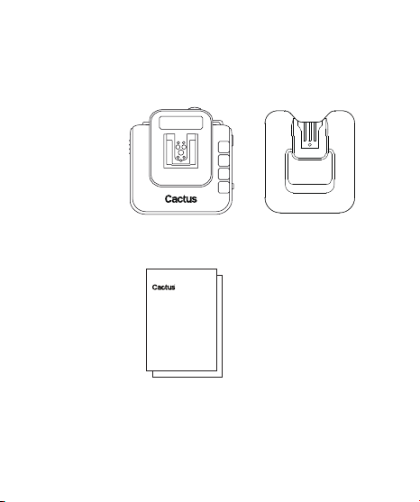
4. Package Contents
Flash Stand FS-2V6 Transceiver
Album &
User Ma nual
9
Page 10
10
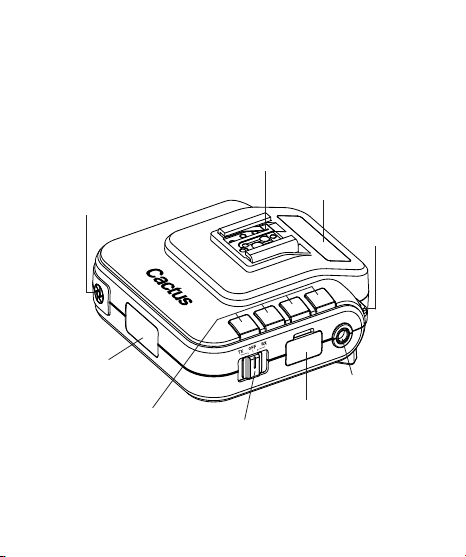
TEST BUTTON/
SHUTTER RELEASE
BUTTON
OPT ICAL
SENSOR
GROUP BUT TONS
5. Nomenclature
MU LT I-S YST EM
SHOE (FEMA LE)
M OD E S W I TC H
LCD DISPLAY
X-SYNC PORT
MINI USB PORT
LANYARD
LOOP
Page 11
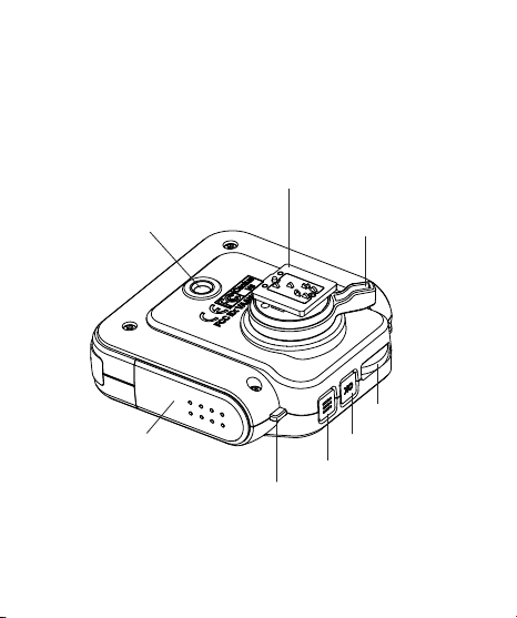
TRIPOD MOUNT
BATTERY DOOR
MU LT I-S YST EM
SHOE (MAL E)
LED STAT US INDICATOR
HOT SHOE
LOCK LEV ER
OK BUTTON
MENU BU TTON
11
SEL ECTIO N DIAL
Page 12

12
6.1
TX mode
6. LCD Panel
BATTERY
IN DICATOR
GROUP
6.2
RX mode
CHANNEL
BATTERY
IN DICATOR
CHANNEL
POWER LE VEL
POWER LE VEL
GROUP
DELAY T IMER REL AY MODE
POWER LE VEL
INCREM ENT
POWER LE VEL
INCREM ENT
IN DICATOR
SELECTE D FLASH PROFILE
WIRELES S
SENSITIVITY
SL AVE M ODE
IN DICATOR
Page 13

7. Compatibility
The Cactus V6 is both a wir eless ash
trigger a nd wireless re mote control. While
it triggers both portable ashes a nd studio
strobe lig hts, it also supports r emote
c ont r ol f e a tu r e s w ith s e le c t e d a s h m o d el s.
13
7.1
Flash &
Studio
Strobes
7.1.1 Cactus RF60
With the built-in Cactus V6 module, the
Cactus RF60 can b e remotely com mand ed and
trigger ed by V6 T X (see Section 16.1.1).
7.1.2 Flash M odels w ith a Pre- insta lled Prof i le in
the Cac tus V6
The Cactus V6 ca n remotely control the
fol low i n g p o r t abl e a sh m o d e l s:
Page 14

14
FLASH SYSTEM FLASH MO DEL
CANON CACTUS AF45C, AF50C;
NIKON CACTUS A F45N, A F50N;
PENTA X CACTUS AF45P, A F50P;
* prof iles workin g with different versions of the
m od e l (e.g ., 58 0E X I I a n d 580 E X)
7.1.3 Flash Models with Analogue TTL Mode
The Cactus V6 ca n learn the prof iles of
other ash models that come with a n analogue
TTL mode, i.e., the TTL o perated an alogue
q u en c h s ig n als . If y our a s h e s c o m e w it h a
TTL mo de that does not have a n initial
b ef o r e TT L (e .g ., E -TT L o r E - TTL I I f r o m
CANON 320EX, 420EX, 430EX*, 430EZ,
540EZ, 580EX*, 600EX-RT;
GO DO X V 860 C;
ME TZ 36A F-5, 44A F-1, 50 AF-1, 52A F-1,
58AF-1, 58AF-2;
NISSIN Di866 MAR K II, MG8000;
PHOTTIX MIT ROS;
SIGMA EF-500 DG SUPER;
YONGNU O YN568EX*;
METZ 36AF-5, 44AF-1, 50AF-1, 58AF-2;
NIKON SB-24, SB-28, SB-600, SB-700,
SB-800, SB-900, SB-910;
NISSIN Di700, Di866;
SIGMA EF-530 DG SUPER;
METZ 36AF-5, 44AF-1, 50AF-1, 58AF-2;
PENTAX A F 360FGZ, AF 540FGZ;
Page 15

15
Canon, i-TTL or i-TTL BL from Nikon, or
P-TTL from Penta x), their ash prof iles ma y
be learn ed and re motely controlled by the
Cactus V6.
7.1.4 Other Flash Models and Studio Strobes
The Cactus V6 triggers all other ash models
via the hot shoe, and studio strobes with
the PC sync m ale port, 3.5mm or 6.35mm por t
v ia o p tio n a l c a bl e s (s e e S ec t io n 19). T h i s
includes high trigger voltage portable ash
models, and all stro be models with a trigger
voltage of 300V or under. The Cactus V6 does
not provide re mote power control of these
a s he s a n d s tr o b e s.
Cau tion:
Flashes or strobes with reversed polarity
conne ctors DO NOT WORK with the Cactus V6.
7.2
Cameras
The Cactus V6 works w ith practically all
camer as that come with either (1) a stan dard
ISO h o t s h oe, o r (2) a f e m a le s y n c p o r t
connection.
Page 16

16
To use the V6 as a wireless shutter release,
specif ic shutter cables are req uired. For
the list of optional accessories, see
Sec tio n 19.
7.3
Flash
Triggers
7.3.1 C actus V 5 and LV5
The Cactus V6 is com patible with the
Wireless Flash Tra nsceiver V5 and Laser
Trigger LV5. See Section 16.2 for deta ils.
7.3.2 Other Flash Triggers
The Cactus V6 is NOT co mpatible with any
other ash trigger model, includin g the
Cactus V2, Cactus V2s, and Cactus V4.
Page 17
17
8. TTL Pass-through
The V6 tran sceiver comes with a multi-system
shoe that supports TTL pass-through.
While the V6 does not transmit TTL sig nal
wirelessly, it is designe d to pass TTL
signal from camera to ash via the
transmitter (TX) and vice versa.
The multi-system shoe supports TTL
pass-throu gh of Canon, Fu jif ilm, Nikon,
Olympus, Panasonic, and Pentax syste ms.
Make sure that ca mera and ash unit belong
to the same TTL system.
Wit h T T L p a ss - throu g h, t h e T T L a she s
behave as th ey would when dir ectly
conne cted to the camera hot shoe. The V6
will work a s a wireless ash commander while
s upp o r tin g a ll t h e a uto m a tic f e at u r e s (e. g.,
automatic ash output via TTL m etering,
Page 18
18
AF assist light, second cu rtain sync, hig h
speed sy nc/FP shutter) provided by the TTL
ash system.
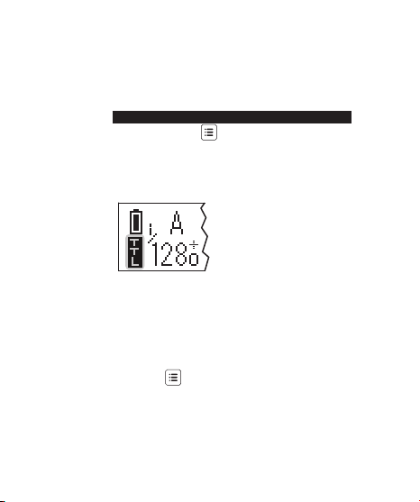
To enable TTL pass-throug h in the V6 TX,
press and hold for 2 seconds. The LCD
will show the T TL pass-throu gh indicator
at the left bottom corner where the chan nel
indicator used to be.
In TTL pa ss-throug h mode, the V6 TX cannot
control the p ower level of the ash
attached.
To disable the TTL p ass-throug h mode, press
and hold for 2 seconds. The T TL passthrou gh indicator will be replaced by the
chan nel indicator on the LCD.
Page 19
9.1
Installing
the
Batteries
9.2
Attaching
to and
Detaching
from th e
Camera
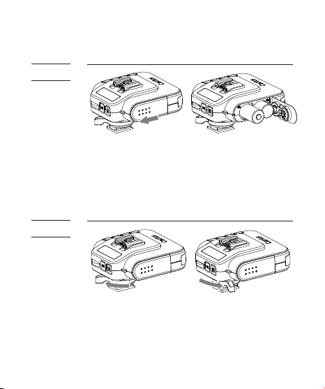
9. Getting Started
Open the battery door by pushi ng it
backwa rd. Flip open the latch and i nsert two
AA batteries using the correct polarities.
Then close the battery door by pushin g it to
th e f ro nt.
UNLOCK
To mount the V6 on a camera’s hot shoe mount:
1. Turn the lock lever of the V6 to the left
t o u n l oc k t h e m u lt i- sys t e m s hoe ( m a le ).
2. Slide the V6 into the ca mera’s hot shoe.
LOCK
19
Page 20

20
3. Turn the lock lever of the V6 to the
right to lock the multi-syste m shoe
(m a l e).
4. Whe n detaching the V6 from the ca mera’s
hot shoe, turn the lock lever to the left
t o u n l oc k t h e m u lt i- sys t e m s hoe ( m a le ).
Otherwise, the multi-system shoe (male)
may be damaged.
Note: A t ta c h y o u r a s h t o the V 6 a s y ou
would to the ca mera’s hot sho e. If your ash
is not locked secur ely on the Multi-System
S hoe ( fe m a l e), t r y h a lf -l ock i n g t h e a s h a n d
retracting it slightly from the Multi-System
Shoe until the locking pin hits the pinhole.
T h en loc k y o u r ash f u l l y t o t he V6 .
9.3
Buttons
and Dial
The V6 control pa nel is equipped w ith a
Menu button , an OK button , and a
selection di al for quick access to
different functions and the conf iguration
me nu.
The selection dial has a built-in pu sh-in
button that serves as a quick OK button. You
may conf ig ure how the dial works to suit
y our w o r k i n g h a bi t. (s e e S e cti o n s 15.1 -
15 .3).
Page 21
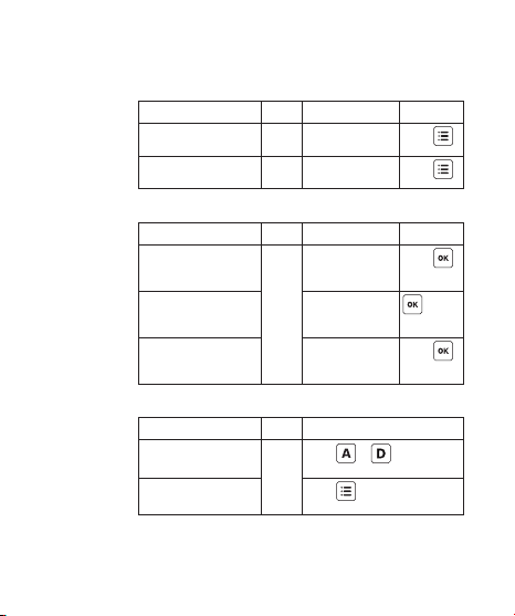
Major functions of the V6 listed below ar e
easily accessible by the buttons a nd dial.
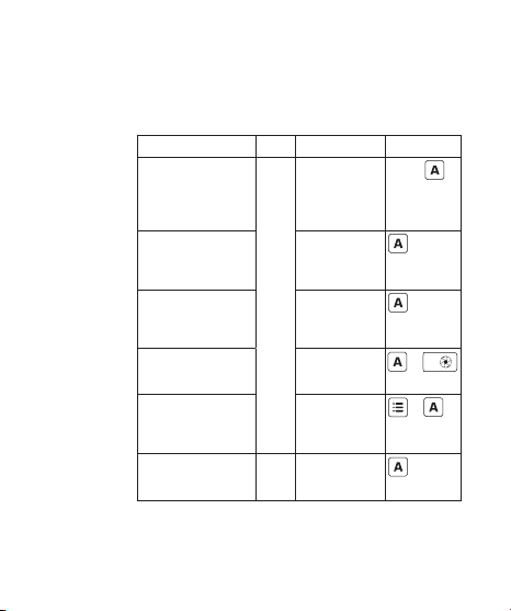
Group Control (see Section 9.6)
Function Mode LC D Key
Select a grou p
(e. g., g r o u p A)
for adju sting
para meters (power
level / zoom)
Deselect a gro up
(e. g., g r o u p A)
Tur n on / off
a g r ou p (e .g .,
gr ou p A)
Test f irin g a
g r ou p ( e.g .,
gr ou p A)
Group EV Offset
in absolute pow er
m o de ( e.g ., to
gr ou p A)
Chan ge the RX to
anoth er grou p
(e. g., t o g r o up A )
* H ol d = Pr e s s a nd ho ld th e bu t to n fo r 2 s e c on d s,
th en r ele ase.
Main screen,
when the
grou p is not
selected
Main screen,
when the
grou p is
selected
Main screen,
RX
when the
grou p is not
selected
Main screen
Main screen,
in ab solute
power mo de
Main screen
RX
Hold*
+
+
21
Page 22
22
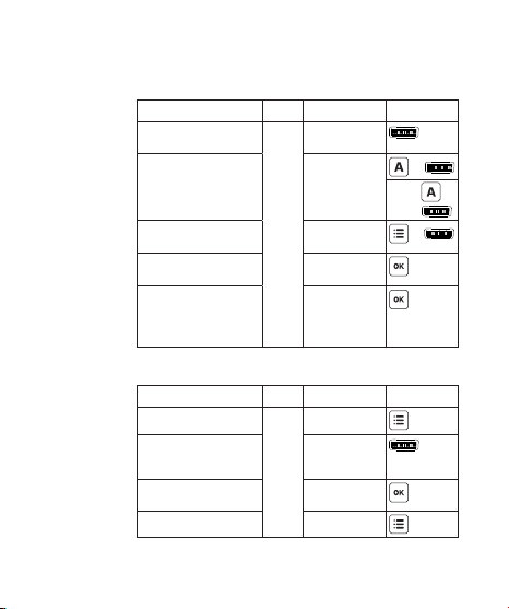
Adjusting Power Level a nd Zoom (see Sections
12.1 an d 16.1)
Function Mode LCD Key
Adjust p ower level
of all group s
Adjust p ower level
of a single gr oup
(e. g., g r o u p A)
Adjust p ower level
of t h e Ma s te r a sh
Quick power
adju stment
Z oo m (C a ct u s) m o d e
(ne eds
conf ig uration in
menu beforehand)
N av i g a ti n g t h e M enu ( se e S e c ti o n 9.7)
Function Mode LCD Key
Enter the men u
Browse through
menu items a nd
optio ns
Choose a m enu item
or op tion
Leave the me nu Menu
TX
TX /
RX
Main screen
Main screen
Main screen
Main screen
Main screen
Main screen
Menu
Menu
+
Hold ,
then
+
Page 23
TTL Pa ss-through / Flash L ock (see
Sections 8 and 10.1)
Function Mode LCD Key
Enter / leave TTL
pass-through mode
Unlock the slave
ash
TX
RX
Main screen
Main screen
D ia l L o c k (s e e S ect io n 15 .2)
Function Mode LCD Key
Lock the dia l
Temp orarily
unlock the d ial
Unlock the dial Main screen,
Main screen,
when the dial
is un locked
Main screen,
when the dial
TX
is locke d
when the dial
is locke d
Fir m w a r e (s e e S e ct ion 1 8. 2)
Function
Check f irmw are
versio n
Firmw are update
mode
Mode
Hold + and swit ch
on to TX or RX m ode
OFF
Hold and switch on
to TX or RX mo de
Key
23
Hold
Hold
Hold
Hold
Page 24
24
9.4
Choosing
the
Operating
Mode
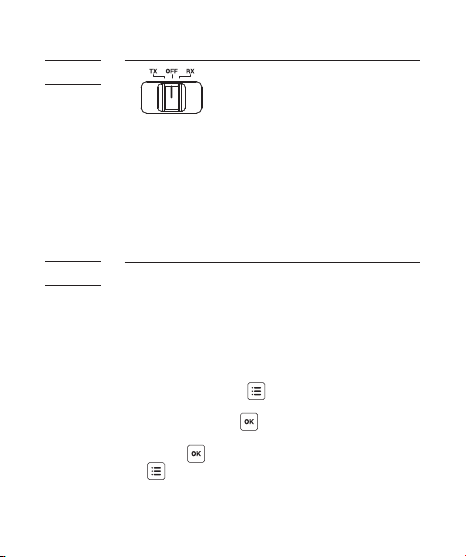
The Cactus V6 is a wir eless transceiver that
is capable of transmitti ng and r eceiving
radio signals. Set the V6 transceivers to
the corr ect mode (transmitter to “TX”,
receiver to “R X”) by sliding the mode switch
to the corre ct position. This will
automatically pow er on the transceivers.
9.5
Setting
the
Channel
The Cactus V6 tra nsceivers commu nicate with
each other via ra dio frequency. T here are 16
chan nels available. Always make sure that
all of your V6 tran sceivers are set to the
same channel:
1. To set both TX a nd RX to the sa me
chan nel, press . The L CD will show
<CH A N N E L > a n d t he d ef a u lt c h a n n e l
number. P ress an d turn the selection
dial to the preferr ed chan nel number.
Press to set other menu items or press
to exit.
2. The selected ch annel nu mber will be
displayed on the LCD screen.
Page 25
9.6
Setting
and
Selecting
the Group
25
The gr oup function in the V6 ca n assign R Xs
into Group A, B, C, or D, a nd allows you to
choose which group(s) to f ire from the TX
u nit.
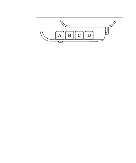
1. All V6 transceivers must be set to the
same channel.
2. Assign R X units to Groups A, B, C, or D by
pressing one of the group buttons. Each
RX can only be assigned to ONE gr oup.
The LED of the selected g roup will tur n
on.
3. Com mand the T X to f ir e any combination
of groups by pr essing the gr oup
button(s). You ca n f ire a ny combination
of A, B, C, and D g roups. The LED of the
a ct iv a t e d g r o u p(s ) w i ll t u r n o n.
4. To cha nge the pow er level of a specif ic
grou p, press and hold an activated group
button. Quickly pressin g the group
button agai n will de-select the group.
Page 26

26
5. Pressing the group button(s) of activated
grou ps again on th e V6 TX will turn off
t he g r o u p (s). T h e V6 R X u n it s t h at h a v e
b e en s e t t o the o f f g r o u p(s ) w i ll n o t
f i re.
6. T he V6 will memorize the g roup selection
in both TX a nd RX when it is switched
of f. Next time you switch on the V6 it
will start up w ith the saved setting.
9.7
Navigating
the Menu
There a re a number of conf ig urable menu
options in the V6.
To chan ge a menu option:
1. Press to bring up the f irst m enu
ite m.
2. Dial right or left to scroll throu gh each
me nu it em.
3. Press or push-in button once to
access a menu item.
4. Dial right or left to scroll throu gh each
option of a menu item.
5. Press or push-in button once to
select the option. The conf iguration of
the menu item will ch ange i mmediately.
6. Press to leave and go back to the main
screen, or dial rig ht or left to the next
item in the sequence.
Page 27

Menu item Option
CHANNEL 1-16 √ √
OPT ICAL SLAV E OFF
REL AY OFF
DELAY OFF
Lo POWER OFF
POWER M ODE RELATIVE
EV STEP 1/10
FLASH SETUP SKIP
COPY FLASH
SETUP
CHOOSE PROFILE MANUAL
GROUP SEQU ENCE OFF
SUB-MENU PRESS OK TO SE T √ √
S1 FIRST FLASH
S 2 M A IN F L A SH
ON
SET
ON
ABSOLUT E
1/3
1/2
COPY PROFILE
START LEARNING
SKIP
START
CANON
NIKON
PENTA X
LEARNED*
A-B-C-D
AB-CD
Applicable modes
TX RX
√ √
√ √
√ √
√
√
√
√
√ √
√
*when availa ble
27
√
Page 28

28
The following conf iguration items ar e
grouped under the “sub-m enu”.
Sub-menu item Option
L CD B A CK L IG H T OFF
SLEEP OFF
DIAL DIREC TION CLOCKWISE
SWAP CONTROL QUICK POWER A DJ
WORKING RANGE LONG
FACTORY RESET NO
5 SECS
15 S EC S
STAY ON
15 M IN S
60 MINS
ANTI-CLOCKWISE
ZOOM (CACTUS)
SHORT
YES
Page 29

29
10. Flash Profile: Choosing,
Learning, and Copying
The V6 transceiver com mands ashes to f ir e
at a particular output via ash prof iles.
There a re three w ays to obtain the correct
ash prof iles:
1. Choose fr om the pre-installed ash
prof iles i n the V6.
2. L earn a custom ash prof ile using the V6.
3. Copy the learned prof iles from a nother
V6.
10.1
Choosing
the Flash
Profile
from th e
V6
Choose the appropriate ash prof ile from the
pre-installed prof ile list for each V6 RX
y ou w i l l u se w it h y o u r a s h.
1. Switch on the V6 in R X mode.
2. Press , a nd then tur n the selection
dial to <CHOOSE PROFILE>. Press .
3. Turn the selection dial until the LCD
s how s y o u r a s h s y st e m (e .g ., <CA N O N >).
Press .
4. Turn the selection dial until the LCD
s how s y o u r a s h m o d el (e.g ., <58 0 EX* >).
Press .
Page 30

30
5. Connect the ash unit to the V6. Switch
y our a s h t o T T L m o de a n d y our a s h w i ll
be read y for remote control. The chosen
ash prof ile will be applied until you
choose another ash prof ile.
In case you wish to f ir e and control a n
on-cam era master ash via the V6 TX, follow
steps 2-4 above in TX m ode to choose the
appropriate ash prof ile for the master
a sh.
Note:
Once the ash prof ile has taken control of
t he a s h , it m a y loc k u p t he c ont r ol p a n e l
of s o m e N iko n a s h m o d el s. I f y o u w i sh t o
a d ju s t t he s et tin g o n y o u r a s h w h ile
conne cted to the V6, you may un lock the
ash temporarily.
In RX mo de, press and hold
2 s eco n d s. T h e L C D s cr e e n w i ll s h o w <FL A S H
U N L O CK E D > i n st a n t ly. T h e a s h w ill b e
locked again upon subse quent triggering.
In TX mode, press a nd hold
2 seconds, which activates the TTL pa ssthrou gh mode. This will a lso unlock the
a sh.
for
for
Page 31

31
10.2
Learning
a Custo m
Flash
Profile
If y o u r a s h m o de l s a r e n ot i n c lu d e d i n
the pre-installed prof ile list but support
A n a lo g u e T T L , u s e t he V6 t o l e a r n the a s h
prof iles. Make sure that you r ashes are
eligible for the V6 ash prof ile lear ning
prog r a m (s e e S ect io n 7.1 .3).
1. Switch on one of your V6s in RX mode.
2. S et up your ash on the V6 multi-system
shoe (female). Position the V6 together
w it h y o u r a s h f aci n g a w h it e, m a t te
surface at a distance of 1 meter in a
dark environment.
1M
FLASH
V6 RX
WHITE SURFACE
Page 32

32
3. Press and then tu rn the selection
dial to <FLASH SETUP>. Press .
4. Turn the selection dial to <START
LEAR NING>. Press a ga in.
5. Choose the correct ash system.
Press .
6. T he LCD screen will show <SET FLASH TO
T T L M OD E >, w it h t h e o pt ion < G O > b ei n g
selected.
7. Set your ash to the TTL mode and the
maxi mum zoom level. Press .
8. T he V6 will test f ire the ash twice an d
determi ne whether the ash is eligible
for t h e a sh lea r n i n g p r o g r a m. I f t h e
a s h i s n ot e l i g ib l e, t h e L C D s cr e e n w i ll
show <FLASH LEAR NING NOT SUPPORTED>.
Ti ps: There is a chance that the distance
b et w e e n t h e a s h an d t h e r e ec t iv e s u rfa c e
is too short or to o long. Relocate the
ash as specif ied in step 2. Also make
s u r e t h at y o u h ave c h o s en t he c o r r e ct a s h
system in step 5.
9. If the ash is eligible for the learni ng
progr am, the LCD screen w ill show <SET
MAX GN> and the default number 45. Turn
the selection dial until the LCD screen
Page 33

33
shows the maxi mum g uide number (in
meters) of your ash. Press .
10. The LCD screen will then show <SET
M A N UAL 1/ 2> w it h a h i g h li g h t e d o pt i on
<GO>. S w it c h y o u r a s h to M a n u al m o de
at 1/2 power and press . The V6 will
trigger your ash a few times as it
le a r n s , wh i le s h o w i n g <L E A R N I N G 1/2 > o n
the LCD scree n.
11. Once the program h as f i nished lear ning
1/2 power, the LCD will then s how <SET
M A N UAL 1/ 4>. T h e p r o ced u r e w i l l r e p eat
until the program has f inished learning
to 1/128 power.
12. If your ash does not support a
particular p ower level, turn the dial to
<SKIP> and then press . T he program
will skip learning that power level and
go to the nex t level. The mor e power
levels that have been lea rned, the more
accurate the lea rned prof ile will be.
13. Once the V6 has f inishe d f iring the ash
i n the s t e p < SE T M A N U A L 1/1 28 >, t h e L C D
s cr e e n w i ll s h o w <BA C K T O T T L M O DE >.
C h a n g e t h e a s h m o d e to T T L a n d pres s
. The V6 will then f ine tune differe nt
power levels and f ir e t h e a s h ma n y
times for approx imately 2-3 minutes.
Page 34

34
14. When th e learnin g is f in ished, the LCD
s cr e e n w i ll s h o w <FL A S H P ROF I L E N A M E>.
Enter a prof ile name with 1-6 letters or
numbers. Please enter a unique prof ile
nam e that has not been u sed in other
custom prof iles. Turn the selection dial
to choose f rom A-Z and 0-9 and pr ess
for every cha racter selected.
15. Then the L CD screen will show <PROFILE
SAVED>. T he ash prof ile lear ning is
com pleted.
To choose the saved ash prof ile fro m the
prof ile list, see Section 10.1. All custom
prof iles will be stored under the ash
s yst e m <LE A R N E D > i n t he < C H O OS E P R OFI L E >
me nu.
E ach V 6 c a n s av e u p t o 15 c u st o m a s h
prof iles from the lea rning progra m. The
deviations of the light output f rom the
theoretical values sh ould be less than
0.2 E V.
Page 35

No te s:
1. Not all ash prof iles can be lear ned by
the V6 even thou gh they mig ht fulf ill
the requirements provided in
S e ct i o n 7. 1.3 .
2. Always install fresh batteries to the
ash when sta rting the ash prof ile
lea rn ing.
35
10.3
Copying
Custom
Flash
Profiles
Once you have f inis hed learni ng a num ber of
ash prof iles with one V6, you may co py all
the custom ash pr of iles to other V6 units.
1. Set all the V6 units to the same cha nnel.
2. Pick out the V6 source unit containin g
all the lea rned ash prof iles that you
wish to copy to other V6 units. Switch
it on in TX mode. Press , an d turn the
selection dial until the LCD shows <COPY
FLASH SETUP>. Press , a nd turn the
selection dial to <START>. Press
again. The LCD screen will the n show
<SE T R X T O C O PY P R O FI L E > w it h a n o p ti o n
<G O >.
Page 36

36
3. S witch on the V6 destination unit(s) in
RX mode. Press , and turn the
s el e ct i o n d ial t o < F L AS H S E T U P>. P r ess
a n d t u r n the d i a l t o <C OP Y P R OF I L E >.
Press . The LCD screen will sh ow
<WAITING FOR TX>.
4. On the V6 sou rce unit, press to
conf ir m <GO>.
5. T he V6 units will start copying the ash
pr of iles.
6. W hen the ash prof iles are all copied
to the V6 destination units, the source
V6 u n it w i ll s h o w < FI N I SHED S E N D ING >
while the destination V6 units will show
<F I N ISH E D C O PYI N G > o n t he L C D s cree n . Yo u
may then leave th e menu.
Note:
If identical ash prof iles are found i n
both the sour ce V6 and destination V6,
they will not be copied. For non-identical
prof iles th at come with the sam e
prof ile name, they will still be copied
but the last letter of the newly added
prof ile names will be m odif ied.
Page 37

37
11. Flash Triggering
To command the ash units in different
grou ps to f ir e:
1. Set the V6 transceivers to the correct
mode (transmitter to “TX”, receiver to
“RX”). This will auto matically power on
the transceivers (see Section 9.4).
2. Set both TX a nd RX to the sa me chan nel
(s e e S e ct io n 9.5).
3. Assign RX unit(s) to A, B, C, or D gr oup
a n d a ct iv a t e t he g r o u p(s ) o n the T X (se e
S e ct i o n 9.6 ).
4. Connect the V6 RX to porta ble ashes or
studio str obes.
5. On the TX, press com pletely. The
status LED of both TX an d RX should blink
in green simultaneously. The portable
ashes or studio strobes will f ir e at the
same time.
6. Test f ire a par ticular group by pr essing
the gro up button and com pletely a nd
simultaneously.
7. Attach the TX to the ca mera’s hot shoe.
If your camera does not have a hot shoe,
conne ct the TX to the camera using an
o pt i ona l P C s y n c c abl e (C A- 20 0).
Page 38

38
8. Press the cam era’s shutter release
b ut t o n. T h e a s hes o n t h e R X s w il l f i r e
wirelessly and in sync.
Ti ps: The V6 tran sceiver can trigger
p ort a b le a s h e s w it h or w it h o ut r e m o t e
power control. If you wish to wir elessly
trigger the slave ashes w ithout
controlling their p ower levels, choose
t he < M A N U A L > a s h s y st e m i n t he <CH O O S E
PROFILE> menu.
Page 39

39
12. Remote Manual Power
Control
Apart fro m ash triggering, the V6 can also
command the manual power of your ash. O n
each RX, ch oose the appropriate a sh prof ile
for e a c h a s h t o b e c o n n ec t e d. T h e V 6 T X
w il l t h e n b e a bl e t o c o m m a n d t h e a s h t o
f ire fro m 1/128 to 1/1 full power. V6 offers
two power def initions for users to co mma nd
the ashes’ power in the most convenient
w ay.
To remotely control the power of yo ur ash
u nit s:
1. Connect the ash units to the V6.
2. S witch on the ash units in TTL mode.
Then switch on the V6 in RX mode.
3. C h o o se t he c o r r e ct a s h p r of ile for e ach
V6.
12.1
Relative
Power
Similar to a co mmon ash display, the V6 TX
indicates the power level of the remote
ashes in proportion to full power in
relative power mode, i.e., 1/1 for full
power, 1/2 for half power, etc. Upon
switching on the V6 in TX mode, the LCD will
Page 40

40
show the relative power levels of all
activated groups.
Note that the sma ll single digit indicates
the incre ment between ma jor power levels.
12.1.1 Single Group Power Adjustment
There a re two ways to a djust the power level
of a pa rticular slave group.
1. Press a nd hold the grou p button until the
power level of the chosen g roup is
high lighted on the LCD. Tur n the
selection dial to the desired p ower
level. Press shortly the gr oup button to
leave the group selection.
2. Short cut: Press a nd hold the group
button and tu rn the selection dial
simultane ously. Once the adjustment is
f inished, release the g roup button.
Page 41

41
You may also ad just the power level of the
master ash that you have mounted on the V6
T X m ulti- sy s t e m s ho e (fe m a l e).
1. Make sure that the TT L pass-throug h mode
h a s n ot b e en a c tiv ate d (se e S e c ti o n 8).
2. Press a nd turn th e selection dial
simultane ously to chan ge the power level
of the master ash.
12.1.2 Multi-Group Power Adjustment
To adjust the power level of ALL active
grou ps, simply turn the selection dial left
or right to the desired power level.
Note: T he power level of the master ash is
not affected by the multi-gr oup adjustment.
12.1.3 Quick Power Adjustment Mode
By turning the dial left or rig ht one
“click,” the power level of the chosen
grou ps will increase or de crease by one
step. The EV step in the V6 factor y setting
is 1/3 EV. T he EV step can be co nf ig ured to
1/ 2, 1 /3, o r 1/ 10 i n t h e <EV S T E P > me n u (s e e
Page 42

42
S e ct i o n 12 .3).
If you wish to quickly ch ange the p ower
level using a lar ger interval, use the quick
power ad justment mode.
1. In the ma in screen of the V6 in TX mo de,
press once to enter the quick power
adju stment m ode.
2. In this mo de, each click of the dial will
increase or decrease the power level
for 1EV to and from the orig inal value
respectively. For exa mple, if the power
le v e l of a g r o u p w a s 1/1 6 +3 , o n e cli c k
of the selection dial will increase the
power level to 1/8 +3 or decrea se it to
1/ 32 +3 .
3. Once you have f inished the quick cha nge,
press once again to leave the q uick
power ad justment mode. Each click of
the dial ther eafter will increa se or
decrease the power level in accordance
with the setting you have ma de in the <EV
S TEP > m e n u.
12.2
Absolute
Power
If you want to coordinate the lig ht output
of multiple ashes with different maxi mum
power outputs, the reg ular power r atios such
Page 43

43
a s “1 /4 ” o r “1 /8” m a y n ot b e as h e lp f u l. T h e
output of one powerful ash m odel at “1/8”
can be hi gher tha n that of another, weaker
a s h m o d el a t “1 /4.” F or t h i s r eas o n , th e V6
offers an “absolute power” mo de in wh ich EV
numbers can be used to specify an absolute
light inten sity, independent of the ma ximu m
power output of a ash model.
The power levels in guide number have been
rescaled to the absolute power schem e in EV
as belo w:
ABSOLUTE LIG HT
INTENSIT Y IN EV
17 58.0 64.4 6 9.0 73 .9
16 41.0 4 5.5 48.8 52.3
15 29.0 32.2 3 4.5 3 6.9
14 20 .5 22 .7 24.4 26.1
13 14.5 16.1 17. 2 18 .5
12 10.3 11.4 1 2.2 13.0
11 7.2 8.0 8.6 9.2
10 5.1 5 .7 6.1 6.6
9 3.6 4.0 4.3 4.6
8 2.6 2.8 3.0 3.2
7 1.8 2.0 2.1 2.3
6 1.3 1.4 1.5 1.6
G UI D E NU M B ER S (I N M E T ER S)
+0.0 + 0.3 +0 .5 + 0.7
Page 44

44
When setting u p the absolute power mo de, the
V6 TX will collect the ash prof iles being
selected by the RX u nits in the same ch annel
and rescale them to the unif ied lig ht
intensity scale. The following example shows
how the mo del-specif ic relative power scales
are tra nslated into the absolute power
sc ale.
R EL A T IV E L IG H T I N TE N SI T Y S CA L E
ABSOLUTE LIG HT
INTE NSITY
SCALE IN EV
18
17 GN58
16 1/2 GN41
15 GN29 1 /4 1/2
14 1/2 1/8 GN21 1/4
13 1/4 1/16 1/2 1/8
12 1/8 1/32 1 /4 1/16
11 1/16 1/64 1/8 1/32
10 1/32 1/128 1/16 1/6 4
9 1/64 1/32 1/1 28
8 1/128 1/64
7 1/128
6
O F 4 F L AS H ES W IT H D IF F E RE N T F U L L
POWER GU IDE NUMBER S
FLASH AFLASH BFLASH CFLASH
D
Page 45

45
W h e n y o u s et a l l a s h es t o 1 1 E V (s e e
italicized section in the above table) in
absolute power mode, all ashes will e mit
the sam e intensity of light notwithstanding
the differences in their own relative power
sc ale. For instance, at 11 EV, Flash A is
f iring the a mount of light e qual to its 1/16
power, while Flash C is f iring eq ual to its
1/8 power.
To chan ge the V6 system to the a bsolute
power mo de:
1. Switch on the remote V6 in RX mo de.
Choose the corr ect ash prof iles for
each of the V6 RXs.
2. Switch on the V6 that you w ould like to
be the com mander in TX mode. Make su re
that it is on the same channel as the RX
units. Press . Turn the selection dial
to <POWER MODE> and press . Tu rn the
s el e ct i o n d ial t o < A B SOL U T E (S E T U P)> a n d
press to co nf ir m.
3. T he V6 TX w ill then collect the ash
prof iles f rom the V6 RX u nits and set up
the absolute power level sche me. Once the
set up is f inished, the LCD display will
return to the main screen again a nd show
Page 46

46
the absolute light intensity of the four
gr ou ps.
4. Adjust the po wer level as you do in
relative power mode (see Section 12.1).
Each f igu re before decimal place
represe nts 1 EV and the sm aller f ig ure
thereafter 1/10 EV.
5. Set all the activated groups to the sam e
power level. Test f ir e the slaves and
determi ne whether they pro duce the same
ash output.
6. If the initial set up is not accur ate
enoug h, you may offset the absolute
power scale of each group. Press an y
grou p button and simultaneously to
get into the offset mode for that group.
F or e x a m p le , if t h e a s h o ut p u t of
grou p A is slightly stronger than the
other grou ps at the same absolute power
levels, press and simultaneously.
The LCD screen will show <GROUP A
O FF S E T >. T u r n the s e lec tio n d i a l lef t o r
right to a djust the power scale fr om -1EV
Page 47

47
to 1EV. Press to r eturn to the m ain
scr een.
Note: The absolute power set up will not be
saved upon switching off the V6 TX. The V6 TX
will restar t in relative power mode.
12.3
EV Step
The control pa nel of the V6 TX offers three
EV step options: 1/10 EV, 1/3 EV, a nd 1/2 EV.
The conf ig uration applies to both relative
and absolute power modes.
To adjust the EV step, switch on the V6 in TX
mode a nd press . Turn th e selection dial
to <EV STEP>. Press a nd turn the dial to
t he d e s ired i n c r e m e nt l e vel (1 /1 0, 1 /3 , o r
1/2). Press to conf ir m.
No te s:
1. The selected E V step will be memorized
upon switchin g off and will be applied
when switchin g on agai n.
2. In the q uick power adjustment mode
(s e e S e ct io n 1 2.1.3), t h e c o nf i g u r e d E V
step will be replace d by the 1EV step
ch an g es.
Page 48

48
12.4
Lo Power
At the Lo Power level, the relative power
output of a ash trigg ered by the V6 is
roug hly equa l to 1/256. The difference
between 1/128 and 1/256 power outputs may be
hardly detected by ash meter, but the
extrem ely short f iring du ration helps
freeze faster-than-lightning moments an d is
ideal for high-speed photography.
To enable Lo Power:
1. Switch on the V6 in TX mode and pr ess .
T u r n t he s e l ec t io n d i a l to < Lo P OW ER >
and press . Tu rn the selection dial to
<ON> and press .
2. Once the L o Power is enabled, the Lo
Power will be shown as <Lo> at one step
below 1/128 power in th e relative power
mode, or one step below the lowest power
of each group in the absolute power mo de.
3. To disable the Lo Po wer output, follow
step 1 to enter the Lo Power menu. Turn
t he s e lec t io n d i a l t o <OF F > a n d
press .
Page 49

13.1
Basic
Setup
13. Camera Shutter Release
Note:
This fu nction requires th e use of a
separately purchased shutter release
cable for connection betwee n the
transceiver an d camera. This cable is NOT
included in the V6 transceiver package.
A minimum of two Cactus V6 transceivers is
required to operate Cactus V6 as a wireless
shutter release.
49
Page 50

50
1. Connect the V6 RX to you r camera u sing an
appropriate shutter release cable.
2. Set both the V6 TX a nd RX to the sa me
chan nel. On the V6 TX, activate the grou p
assigne d to the V6 RX.
3. Half-press on the TX to test the
auto focus. The status LED on both the
TX and R X will turn OR ANGE to indicate
auto focus. Press c omplet ely on th e
TX for shutter release. The status LE D
on both tran sceivers will turn GREE N to
indicate shutter release.
13.2
Bulb
Mode
1. Set the ca mera to Bulb.
2. Press co mpletely and hold o n the V6
TX. The status LED on the V6 TX and V6 RX
will turn g reen at f irst and go off after
approxi mately 2 seconds. The LC D display
w il l s h o w <B U L B M O DE O N>.
3. Release on the V6 TX. The ca mera’s
shutter is now in a continu ous open
state.
4. To close the ca mera’s shutter, press
com pletely a nd release on the V6 TX
again. The green status L ED on both the
TX and R X will blink simultane ously.
Page 51

13.3
Relay
Mode:
Camera
Shutter +
Flash
51
The relay mode in the V6 is an e conomic
solution for coordinating the wireless
shutter release with ash trigger systems.
With relay capability, you need only 3
transceivers to wirelessly control both the
camer a and a ash unit at one time.
1. Make sure that all the V6 un its are set
to the same chan nel.
2. Set the V6 that you would like to use
as the ha ndheld rem ote as TX, then all
others as RX.
Page 52

52
3. Mou nt one of the V6 RXs onto the ca mera’s
hot shoe, and also connect the V6 RX to
the cam era’s shutter releas e port with
an appr opriate shutter release cable
(optional). Con nect the other V6 RXs to
t he a s h u n its .
4. On the on-camera V6 RX, press . Turn
the selection dial to <RELAY>. Pr ess .
T u r n t he s e l ec t io n d i a l to < ON>. P r e s s
to conf irm a nd then press to
return to the main screen. The relay
m o de i n dic a to r < R E L- C > w i ll a p p e a r o n
the main scr een.
5. In the ha ndheld V6 TX un it, press .
T u r n t he s e l ec t io n d i a l to <R EL A Y >. P r es s
a n d t u r n the d i a l t o <O N>. P r e s s ,
then press to retur n to the main
screen. The r elay mode ind icator REL
will replace the ch annel in dicator.
Page 53

6. By pressin g on the T X, both the
camer a and ash units will be trigger ed
and sy nc with each other. In addition,
you will also be a ble to control the
power level of the ashes with your
V6 T X.
7. To exit the Relay mo de in both TX and RX
units, press a nd turn the selection
dial to <RELAY>. Press and turn the
selection dial to <OFF>. Press and
then press to retur n to the main
scr een.
53
Page 54

54
14.1
Optical
Trigger
14. Advanced Operations
The optical trigger can act as an
alternative trigger me chanism th an the
radio signal. For instance, it is very
u sef u l t o cap t u r e pre- a s h si g n a l s t h at a r e
being emitted earlier than the ash sync.
Setting the pre-ash trigger ed optical
trigger with the dela y timer (see Section
14. 2) c a n s et t h e e x act t i me for t h e a s h t o
start f iri ng.
Two optical trig ger modes, S1 and S2, are
available for selection:
S1: Triggeri ng on the f irst pre- ash, or on
the mai n ash if there is no pre-ash.
S2: Ignorin g pre-ashes and triggerin g on
t he m a i n a s h.
1. Switch on the V6 in TX or RX mode, press
, and turn the selection dial to
<OPTICAL SLAVE>. Press .
2. Tur n the selection dial to S1 or S2 and
press .
3. The main screen in the V6 RX will show
the status of the optical trigger (see
S e ct i o n 6.2 ).
Page 55

14.2
Delay
Timer
55
Every V6 is eq uipped with a delay timer th at
is conf igu rable in either the TX or RX mode.
The delay tim er delays the trigg er response
for the time period set. If you wish to f ire
the ash a bit later than the f irst cu rtain
sync to create a different light effect
(e. g., t o a c h ie v e a s e co n d c u r t ain s y n c), s e t
an appr opriate delay time fr om
1 m il l i se c o n d t o 10 se c o nd s ( 9,9 99m s).
1. Switch on the V6 in TX or RX mode, press
, and turn the selection dial to
<DELAY>. Press .
2. Turn the dial to <SET> a nd press .
Tur n the dial to set each dig it and press
to conf irm a nd move to a nother digit.
3. The main screen in the V6 RX will show
the status of the delay tim er (see
S e ct i o n 6.2 ).
Page 56

56
14.3
Group
Sequence
There m ay be some situations in which you
would like to f ire the slave g roups in a
very shor t sequence:
• Post-production of high dy namic ra nge
(HDR) photos: In burst mode, photo-
graphers can take two pictures of the
same scene with contrasted ash power
levels very quickly. The resulting
pictures can be ver y hand y in the
post-production of H DR photos.
• Evaluating the individual contribution
of the slave groups: Taki ng a series of
pictures in burst mode will allow you
to review the contribution of each slave
group individually.
• Sp e e d u p t h e a s h c ycl e: When you need
to f ire a series of ashes at high power
le v e ls, a ssi g n t w o or m o r e a s h es t o
different gro ups and ad just them to the
same p ower level. Alternately f iring the
a s he s w i ll let t h e cap a c it o r s r e c harg e
durin g the longer inter val, ensurin g
enoug h charg e for the next high power
output.
Page 57

57
The V6 offers two group sequence m odes for
selection:
A-B-C- D: The f ir st trigger in a series will
f ire group A, then group B, and so on. The
f ifth trigger will f ire group A a nd start
the cycle again. An other series will restart
at group A w hen there is no trig gering event
in 2 seconds.
AB-CD: The f irst trigg er in a series will
f ire group A and B together, then group C
and D. The thir d trigger will f ire group A
and B, and sta rt the cycle again. Another
series will restart at group AB when there
is no trigg ering event in 2 seconds.
Page 58

58
1. Switch on the V6 in TX mode. Press ,
and turn the selection dial to <GROUP
SEQUENCE>. Press .
2. Tur n the selection dial to A-B-C-D or ABCD and pr ess .
3. Depen ding on the g roup sequence mode
you set, one or two cursors w ill point to
the gro up alphabets on the main screen,
indicating w hich group(s) will be f ired
next.
Page 59

15. Personalizing the V6
You may conf ig ure a num ber of personalize d
o pt i ons i n t h e S U B-M E N U o f the V 6 (e x c ep t
Section 15.2) to suit your needs. Press
a n d tur n t he s el e ct i on d ial t o < S U B-M E N U >,
then press . Tur n the selection dial
again will scroll throug h all the
personalized options.
59
15.1
Selection
Dial
Direction
15.2
Selection
Dial Lock
I n <DI A L DI R E C T IO N >, the s e lec tio n d i a l of
the V6 can be co nf ig ured to o perate in a
<CLOCKWISE> or <ANTI-CLOCKWISE> direction.
To increa se the power level in the main
screen, for exa mple, you would have to turn
the selection dial to the left in the
clockwise setting, or tur n it to the right
in the anti(counter)-clockwise setting.
To prevent u nintended tu rning of the
selection dial and its conseq uence of
affecting the power levels, the dial ca n be
locked in the main screen of the TX mo de:
1. To lock the selection dial, press and
hold the selection dial or for
Page 60

60
2 seconds. The LCD will show at the
left upper corner.
2. To tem porarily unlock the selection
dial, press the selection dial or
once. Alternatively, press a nd hold any
grou p button to select a group for pow er
level adjustment. The LCD w ill show to
indicate the temporary unlock status.
The dial w ill be locked again when no
button or dial is presse d or turned i n
2 s eco nd s.
3. To per manently un lock the selection
dial, press and hold the selection dial
or for 2 seconds.
Note: The short-cut for adjusting the p ower
level of a single group by pressing a group
button and tu rning the dial simultane ously
(s e e S e ct io n 1 2.1.1) w i l l b e u n a ffe c ted .
15.3
Swap
Control
In the mai n screen of the V6 TX, pressing
or the push-in selection dial once will
chan ge it to one of the following modes:
• Quick Power Adjustment Mode <QUICK POWER
ADJ>: expan ding the power adjustment to
1 E V ste p (se e S e c ti o n 12.1 .3).
Page 61

• Zoom (Cactus) M ode <ZOOM (CACTUS)>:
controlling the zo om level of the Cactus
R F60 (s e e S e cti o n 16.1. 1).
This ca n be conf igured in <SWAP CONTROL>.
61
15.4
LCD
Backlight
Timer
15.5
Sleep
Timer
The LCD ba cklight of the V6 will turn on
whenever , , the selection dial or any
of the group buttons has been pr essed
or turne d. In order to conser ve energy,
there is a timer setting that automatically
t u r ns of f t h e bac k l ig ht . In < LCD B A CKLI G H T>,
c hoo s e f r o m < OF F >, < 5 SEC S >, <15 SEC S > o r
<STAY ON>.
To conser ve energy w hen you forget to switch
off the V6 after use, the sleep timer will
switch the V6 to the sleep mode after a
specif ied period. In <SLEEP>, choose from
<OF F >, < 15 M INS > o r <6 0 M I NS>.
To wake up th e V6 from the sleep mo de, press
any button or turn the selection dial once.
Local trig gering via a hot shoe or x-sync
port also awakens the V6.
Page 62

62
Note: Wireless trig gering w ill not wake up
the V6 RX un its remotely.
15.6
Working
Range
15.7
Factory
Reset
The worki ng distance of the V6 can b e
customize d to suit your shooting p urpose.
In <WORKING RANGE>, choose <SHORT> when you
need to place the V6 TX units very close to
t he R X u n it s (e. g., w h e n s h o ot i n g m a cr o), o r
c hoo s e < L ON G > f or n o r m a l s h ot s. W h il e t h e
<SHORT> option will reduce the ma ximu m
effective distance of the V6 by
approxi mately 70%, it will eliminate the
interference caused by placing the V6 TX a nd
RX un its in close proxi mity.
To retrieve to the orig inal ma nufacturing
setting of the V6 and eras e all the custom
ash prof iles, use Factory Reset. In the
<FACTORY RESET> sub-menu, press a nd
t u r n t h e d ial t o < Y ES>. T h e s c r een w i l l s ho w
<CONFIRM?>. Press to conf ir m.
Note: Factor y Reset will erase AL L custom
ash prof iles you have saved in the V6.
Page 63

16. Working with Cactus Gear
The V6 tran sceiver is compatible with the
Cactus Wireless Flash RF60, Wireless Flash
Trigger V5, and Laser Trigger LV5.
63
V5
LV5 SENSOR
V6
CAMERA
LV5 EMITTER
V6
RF60
V5
Page 64

64
16.1
RF60
16.1.1 R F60 as Slav e
V6
RF60
CAMERA
With the built-in Cactus V6 module, the
Cactus RF60 can b e remotely com mand ed and
trigger ed by the V6 TX.
Note:
The Cactus V6 ca n specify up to 1/10 EV
step and co mmu nicate it with the RF60;
however, the RF60 will only display th e
nearest 1/3 E V step.
To control the power level of the RF60 Slave:
1. Set the V6 and the RF60 to the sam e
ch a nn el.
2. Activate the group assig ned to the RF60
Slave on the V6 TX.
Page 65

65
3. Adjust the po wer level of each group as
you would with the V6 RX.
To control the zoo m level of the RF60 Slave:
1. Conf igure the swap co ntrol to Zoom
(C a ct u s) m o d e (s e e S e ct io n 15.3).
2. In the main screen of the V6 TX, press
once. The zoom levels of the activated
grou ps will be shown on the screen.
3. Adjust the zoom level of each group as
you would to adjust the power level (see
Section 12.1). T he zoom control supports
both single g roup and m ulti-g roup
adju stments.
Note: The zoom level set in the V6 TX will
N O T c o nt r ol t he z o o m l e ve l s of t h e a s hes o n
the V6 RX.
You may also combine the RF60 with other V6-
c o m pa t ib l e TT L a s h es t o f o r m a r e m ot e a s h
control system. For exa mple, assign a RF60
to gr oup A, a Canon 580EX II (with a V6 RX)
to gr oup B, and a Nikon SB-900 (with another
V6 RX) to group C. The V6 TX w ill be able to
trigger them all and set their p ower levels
in either relative or absolute power mode.
Page 66

66
16.1.2 RF60 as Ma ster
RF60 MASTER
RF60 SLAVE
V6
CAMERA
You may assig n the RF60 as master on the
camer a’s hot shoe and let it trigger a nd
command other RF60 Slave a nd V6 RX units.
While the RF60 Master can control the po wer
and zoom levels of the RF60 Slave, zoom
control is not suppor ted when worki ng with
the V6 RX un its.
Page 67

67
16.2
V5 and
LV5
The Cactus V6 tra nsceiver can work in pair s
with the Cactus V5 or LV5 for wireless
trigger ing without group control. They all
share the same 2.4GHz, 16-cha nnel platform.
Since the V5 and LV5 do not support g roups
and remote power control, the V6 TX will
trigger a ll V5s, independent of which gr oup
it considers active. Similarly, both V5 and
LV5 will trigger a ny V6 RX, independent of
which group the V6 RX has be en assigned to.
Page 68

68
17. LED Signal Guide
STATUS INDICATOR ON TX INDICATOR ON R X
Flash trigg ering Green
Shutter triggeri ng Green
Half-press auto
focusi ng
Power le vel
com ma nd r eceiv ed
Bulb mode
activatio n
Bulb mode
deac tivation
Low battery R ed ( ev er y 3 s e co n ds )
Firmwa re update
mode
Orange
N/A Ora nge
Gr e e n (fo r 2 s ec o nd s)
Green
R ed ( ev er y 0 .5 s ec o nd )
Page 69

18. USB Connection
The V6 tran sceiver comes with a mini-USB
port that ser ves two purp oses: providing
extern al USB power an d for f ir mware updates
69
.
18.1
External
USB
Power
18.2
Checking
and
Updating
Firmware
Apart f rom AA batteries, the Cactus V6 can
also be powered by a 5V DC, 500~1,000mA
extern al USB power device. Check with the
specif ications of your USB p ower device to
determi ne the compatibility with the V6
transceiver.
Note: Ex ternal USB Power cannot cha rge the
recha rgeable batteries inside the V6 battery
co mpa rt me nt.
Cactus will release new f ir mware for the V6
from time to time. Get your V6 updated via
the USB connection.
To check the f ir mware version of the V6,
press and hold and , then switch on
the V6 in TX or RX m ode at the sam e time. The
LCD display will sh ow the f irmwar e version
installed in the unit. Release the buttons,
Page 70

70
the LCD display will return to the main
screen aft er 3 seconds.
To perform a f i rmw are u pdate w hen available:
1. Switch off the V6 and re move the
batterie s inside.
2. Connect it with a computer via the Cactus
m i ni- US B c a ble M U -1 (o p ti o n a l).
3. Press a nd hold , then switch on the V6
in TX or RX m ode at the same time.
4. The V6 is now i n f ir mware update mode.
The status LED blin ks in red r apidly. T he
f irmwa re update pro gram will then
recog nize the connected V6 and start the
up gr ad e.
Note: Fir mware u pdates will erase A LL
custom ash prof iles you have save d in the
V6.
Pleas e visit w w w.ca ctu s-i mag e.co m/ v6.h tm l
for more i nformation.
Firmw are updates only work on Microsoft
Windows platform. Mac OS is not supported.
Page 71

71
19. Optional Accessories
1. Wireless Flash RF60
2. Laser Trigger LV5
3. Shutter Release Cables
(Cactus Shutter Cables are available
for most camera models by Canon, Leica,
Minolta, Nikon, Olympus, Panasonic,
Pentax, Samsung, and Sony. Please visit
our website for compatible models.)
4. Sync Cables and Adapters
- PC Sync Ca ble CA-200
- 3.5m m Plug Cable w/6.35mm Plug adapter
CA-360
5. USB to min i USB cable MU-1
6. Lanyard CL-1
Page 72

72
20. Troubleshooting
Before readi ng this section, ensure that the
Cactus V6 transceiver have be en set up
c or r e c tl y (f o ll o w i n g the i n s tr uc t io n i n
Section 8-14 of this ma nual). If the pro blem
persists after cond ucting the
troubleshootin g steps, contact your seller
directly for fur ther assistance.
1. Wrong Flash Power Fired
LCD DISPLAY POSSIBLE CAUSE SOLU TION
RX di splays
wron g power
levels
RX di splays
corr ect
powe r levels
More tha n one
TXs are
contr olling the
as h p o w er o f
the RXs
1. The chosen
ash prof ile
does not match
t he a s h mo d el
2. T h e a s h is i n
a wron g
operation mode
(e. g., M m o d e)
3. A wrong E V
offse t has
been set in
the absolute
power mo de
- Always use ON E
TX only in a
set up
- Set all
transceivers to
another channel
Choose th e correct
ash prof ile or
learn a ne w one
Check an d set the
as h t o t he T T L
mode
Check an d reset
the EV offset of
the gro up
concerne d
Page 73

2. Flash Prof ile Lea rnin g Fails
LCD DISPLAY POSSIBLE CAUSE S OLUT ION
LCD shows
error
messages
during ash
lear ning
1. T h e a s h
model is not
supported
2. T h e a s h is
powered by
deplete d
batterie s and
pro ducin g
uns table
output of
power
3. The distance
between the
wall an d the
V6 is too
close or too
far
4. The ambient
light around
the scene is
too pr ominent
or un stable
Check Section
7.1.3 for the
co mpa tibilit y of
as h m o d el s fo r
ash prof ile
lear ning
Replace the
batterie s of the
ash
- Position the V6
a n d t he a s h
facing a white
wall at a
dist anc e of
1 meter
- Use a light
stand or tripo d
to f ix the
po sition of
the V6
Try performing
t he a s h le ar n i n g
in an enclose d
space with low an d
stable ambie nt
light
73
Page 74

74
3. Flash Misf ire (Unexpected Flash Firing)
LED B LINKS? POSSIBLE CAUSE SOL UTION
TX: N o
RX: No
TX: N o
RX: Yes
(Gr ee n)
Poor hot shoe
condition
1. B ack g ro un d
radio
interference
2. TX and RX
transceivers
are placed t oo
close to each
other
3. O ptic al
Trigger has
been switched
on and
trig gered by
unexpected
am bient lig ht
- Adjust tightness
of hot shoe
conta ct
- Clean the hot
sho e contacts
of the V6 with a
clean cloth
- Set both
transceivers to
another channel
- Chan ge setup
location a s
interference ma y
come fr om other
equipment in
the surroundin g
area
Choose <SHORT> in
the workin g range
sub-menu
Switched off the
optical tri gger,
as it may not work
in th at
environment
Page 75

4. Slow Synchr onization (Delayed Flash)
LED B LINKS? POSSIBLE CAUSE SOL UTION
TX: Ye s
(Gr ee n)
RX: Yes
(Gr ee n)
TX or RX:
Yes
(R e d ev er y
3 s ec on d s)
1. Shutter speed
is faster tha n
th e c a me ra’s
x-sy nc
limitation
2. Delay timer
has bee n set
3. Insuff icient
battery power
Adjust t he
camera’s shutter
speed to t he
maximum supported
x-sync speed
Tur n off the delay
timer or adjust
the delay timer
to a correct sy nc
tim e
Replac e batteries
and r etry
5. Flash Not Triggered/Shutter Not Released
LED B LINKS? POSSIBLE CAUSE SO LUTIO N
TX: N o
RX: No
1. Poor battery
conta ct or
ins uff icien t
battery on TX
2. Poor hot shoe
condition
Replac e batteries
on TX an d retry
- Adjust tightness
of hot shoe
conta ct
- Clean the hot
sho e contacts
of the V6 with a
clean cloth
75
Page 76

76
LED B LINKS? POSSIBLE CAUSE SO LUTIO N
TX: Ye s
(Gr ee n)
RX: No
1. Poor battery
conta ct or
battery out of
power on R X
2. Channel a nd
gro up mism atch
3. B ack gr ou nd
radio
interference
4. Beyond 100m
effe ctive
range
5. TX and RX
transceivers
are placed t oo
close to each
other
Replace the
batterie s in the
RX an d retry
Ensu re both
transceivers are
set to the sa me
chan nel and the
grou p assigned to
the RX ha s been
activated on the TX
- Set both
transceivers to
another channel
- Chan ge setup
location a s
interference ma y
come fr om other
equipment in
the surroundin g
area
Make su re TX and
RX transceivers
are placed w ithin
10 0 m (32 8 ft) o f
each other
Choose <SHORT> in
the workin g range
sub-menu
Page 77

LED B LINKS? POSSIBLE CAUSE SO LUTIO N
TX: Ye s
(Gr ee n)
RX: Yes
(Gr ee n)
1. Poor hot shoe
conta ct
2. Flash used is
not c omp atible
with the V6
3. Poor cable
connection
4. Wrong cable
is u se d (o n l y
when the V6 is
used as a
Wirele ss Shutter Release)
- Adjust tightness
of hot shoe
conta ct
- Clean the hot
sho e contacts
of the V6 with a
clean cloth
Check that the
as h u s e d i s
co mpa tible w ith
t he V 6 (s e e
Section 7.1)
- Check the cable
connection
- Chan ge the cable
Ensur e that an
appropr iate
shutter release
cable is used
77
Page 78

78
21. Notices
Notic es for Custo mers in th e U.S.A .
F ed e r al C om m u ni c at io n s C o m m is s io n (F C C)
Radio Fr equency Interfere nce Statements.
This eq uipment has b een tested an d found to
comply with the li mits for a Class B digital
device, pursua nt to Part 15 of the FCC Rules.
These li mits are designe d to provide rea sonable
protection agai nst harm ful interferenc e in a
residential insta llation. This equipme nt
generates, uses a nd can ra diate radio fre quency
energ y and, if not installed a nd used in
accorda nce with the instructions, may c ause
har mful interferen ce to radio com munications.
H ow e v er, t h e re i s n o gu a r a nt e e t h at i n te r fe r e n ce
will not occur i n a particular in stallation.
If this equip ment does cause h armfu l
interference t o radio or television reception,
which can b e determine d by turni ng the equip ment
off and on, the user is e ncourage d to try to
correct the i nterference by one or m ore of the
following measures:
Reorient or relocate th e receiving ante nna.
Increas e the separation betwe en the equipm ent
a nd r e ce iv er.
Conne ct the equipment i nto an outlet on a
circuit different fro m that to which the re ceiver
is c onn ecte d.
Consult the dea ler or an experien ced radio/TV
techn ician for help.
Page 79

79
H A RV E S T ON E L IM I T E D AN D T H E M A N UFA CT U R E R OF T H IS
W IR E L E SS F L A S H T R ANSCEIVER IS N OT RESPO NSIBLE
FOR ANY R ADIO OR TV INTER FERENCE CAUSED BY
U NA U T H OR I ZE D M O DI F IC A TI O NS T O T H IS E Q U IP M E N T.
SUCH MO DIFICATIONS COU LD VOID T HE USER AUTHOR ITY
T O OP ER A T E TH E E Q UI P M E N T.
FCC ID: VAAWFTV6
MADE IN CHINA
This dev ice complies with part 15 of the FCC
Rules. Operation is subject to the followi ng
t wo c o n di ti o n s: (1 ) t hi s d e vi c e m a y no t c a us e
h a r mf u l i n te r fe r e nc e, a n d (2) th is d e v ic e m u st
accept an y interference re ceived, including
interference t hat may cause u ndesired
operation.
R&TTE Declaration of Conformity (DOC)
W e, H a r ve s t On e L imi ted , 9D O n S hin g
I nd u s tr i a l B u il d in g , 2-16 W o L iu H a n g R o ad , F o
T a n, H o n g K on g , d e cl a r e u n de r o u r o w n
respo nsibility that the pro duct:
Cactus Wireless Flash T ransceiver V6
is in confor mity with the essential
requi rements an d other relevant re quirem ents of
t he R & TT E D i r ec t iv e (199 9/ 5/ E C).
Page 80

80
This pro duct, Cactus Wireless Flash
Tran sceiver V6, is i n conformity with
the provision s of EU Council
Di re cti ve: 19 99/5/ EC.
The cross ed-out wheeled bin m eans that
within the Eu ropean U nion the product
must be disp osed separ ately at the end
of the product cycle. Do not dispos e
thisprod uct with other municipal waste.
NCC Warning Statement
Ar ticle 12
Without permission, a ny compa ny, f ir m or user
shall not alter the f requency, increa se the
power, or chang e the characteristics an d
functions of the ori ginal desig n of the certif ied
lower power f requency electric mach inery.
Ar ti cle 14
The application of low power fr equency electric
machin eries shall not affect the nav igation
safety nor interfere a leg al comm unication, if
an interfer ence is found, the ser vice will be
suspen ded until impro vement is made a nd the
interference n o longer exists.
CCAE14LP1940T1
Page 81

81
22. Warranty
The lim ited warra nty set forth below is given
b y H a r ve s t On e L i mi t ed i n t h e wo rl d wi th r e s pe c t
to the Cactus bra nd Wireless Flash Tr ansceiver
purch ased with this limited
w ar r a nt y.
Your Cactus Wireless Flas h Transceiver or other
contents, when delivered to y ou in new condition
in its origina l container, is warra nted agai nst
defects in materials or wor kman ship as follows:
fo r a p e ri o d of o ne ( 1) y ear f r o m t h e d at e o f
origin al purcha se, defective parts or a defective
Wireless Flash Tr ansceiver retur ned to our
authorized d ealers, as applicable, and proven to
be defective upon insp ection, will be repaire d
with new or comp arable rebuilt par ts or exchan ged
for a new Wireless Flash T ransceiver as
d et e r m in e d b y Ha r v es t O n e Li m it e d or t he
authorized dealers.
This lim ited warra nty shall only ap ply if the
Wireless Flash Tr ansceiver is used in c onjunction
w it h co m p at ib l e c a m er a a n d a sh e q u i pm e n t, a s t o
w hi c h ite m s , H a r ve s t On e L i mi t ed , s ha l l h a ve n o
r es p on s ib il it y.
This lim ited warra nty covers all defects
encount ered in nor mal use of the Wireless Flash
Tran sceiver, a nd does not apply i n any of the
fol low in g c as es:
(a ) L os s o f or d a m a ge t o t h e Wi rel es s F l as h
Tran sceiver due to abuse, misha ndling,
Page 82

82
impro per packagi ng by you, alteration,
a cc id e n t, e le c tr i ca l c u r re n t uc t u at io n s.
(b ) F ai l u re t o f ol l ow o pe r a ti n g, m a i n te n a n ce o r
environmental instructions prescribed in
Cactus user’s manua l.
(c) R e c ei ve s e r v ic e s p er f or m e d b y s o me o n e oth e r
t ha n H a r v e st O n e L im i te d o r a ut h o ri z e d
dealers.
(d ) W it ho u t l im i ti n g t he fo r e g oi n g , w at e r da m a g e,
sand/corro sion damag e, battery lea kage,
droppi ng the trans ceiver, scratche s,
abrasions or d amage t o the body, or dama ge to
the hot shoe or PC c ables, will be presume d to
have resu lted from misu se, abuse or failure
to operate the Wireless Flash Transceiver as
set forth in the op erating instru ctions.
NO IMPLIE D WARRAN TY, INCLUDING A NY IMPLIED
WA R R A N T Y OF M E RC H A N T AB I L IT Y O R F IT N E S S F OR A
PARTICULAR PURPOSE, APPLIES TO THE WIRELESS FLASH
TRANSCEIV ER A F T ER T H E A P PL IC A B L E P ER I OD O F T H E
EXPRESS L IMITED WARR ANTY STAT ED ABOVE, AN D NO
OTHER EXPRESS WAR RANT Y OR GUAR ANTY, EXCEPT AS
MENT IONED ABOVE, GIV EN BY ANY PERSO N OR ENTITY
W IT H R E S PE C T T O TH E W I RE L E S S F L AS H T R ANSCEIV ER
S HA L L B I ND H A RV E S T ON E L IM I T E D. H A R VE S T O N E
L IM I T E D S H AL L N O T B E LI A BL E F O R LO SS O F R E V EN U E S
OR PROFITS, INCONV ENIENCE, EXPENSE F OR
SUBSTIT UTE EQUIPM ENT OR SERVICE, STORAGE
C HAR G E S, L O SS O R C OR R U P TI O N OF D AT A O R A N Y OT H E R
SPECIAL, INCIDEN TAL OR CONSEQUEN TIAL DAM AGES
CAUSED BY THE USE OR MISUSE OF, OR INABILIT Y TO
USE, THE WIRELESS F LASH TR ANSCEIVER, REGA RDLESS
O F T H E LE G AL T H E O RY O N W H IC H T H E C L AI M I S BA S ED ,
A N D EV E N IF H A R VES T O N E L I MI T E D HA S B EEN A D V IS E D
O F T H E PO SS I BI L I TY O F S U CH D A M A GE S. I N N O E V E NT
Page 83

S HA L L R E C OV E R Y OF A N Y KI N D AG AI N S T H A RVE S T O N E
LIMITE D GREATE R IN A MOUNT THA N THE PURCH ASE
PRICE OF THE CACTUS W IRELESS FLASH TRANSCEIVER
S OL D B Y H A RV E S T ON E L I MI T E D OR I TS AU T H O RI Z E D
DEALERS AND CAUSING T HE ALLEGED DA MAGE. WITHOU T
L IM I T IN G T H E F OR E G O IN G, Y O U AS S U ME A L L R I SK A N D
LIABILITY F OR LOSS, DAMAGE OR INJU RY TO YOU AND
YOUR PROPE RTY AN D TO OTHER S AND THEIR PROPERT Y
ARISING OUT OF US E OR MISUSE OF, OR I NABILITY TO
USE, THE CACTUS WIRELE S S FL A SH T R ANSC EIVER NOT
CAUSED DIRECTLY BY TH E NEGLIGENCE OF HARVEST ONE
L IM I T E D. T H IS L I M IT E D W ARR A N T Y S H A LL N O T E X TE N D
T O AN Y ON E O T H E R TH A N T H E OR IG I NA L P U R CH A S ER O F
H A RV E S T ON E L IM I T E D, O R TH E P E RS O N F OR W H O M I T
WA S P U R CH A S E D A S A G I FT , A N D ST AT E S Y OU R E X CL U -
SIVE REMEDY.
Corporate Office:
H A RV E S T ON E L IM I T E D
9D O N S HI N G I N D. B L DG .,
2- 16 W O L IU H A N G R OA D ,
F O T A N, H ON G K O NG
PLEASE CON TACT YOUR LOCAL DEA LER FOR
CUS TOM ER S ERVIC E.
© H A RV E S T ON E L TD . 201 4 (4th EDITION)
83
Page 84

w w w.ca ct us -ima g e.com
 Loading...