

Page 1

Cactus Technologies, Limited
Industrial Grade
CFast Card
Product Manual
October 30, 2012
Corporate Headquarters
Suite C, 15/F, Capital Trade Center
62 Tsun Yip Street, Kwun Tong
Kowloon, Hong Kong
1
Page 2

Cactus Technologies, Limited
The information in this manual is preliminary and is subject to change without notice. Cactus Technologies ® , Limited shall not
be liable for technical or editorial errors or omissions contained herein; nor for incidental or consequential damages resulting
from the furnishing, performance, or use of this material.
Cactus Technologies® makes no warranty, representation or guarantee regarding the suitability of its products for any
particular purpose, nor does Cactus Technologies® assume any liability arising out of the application or use of its products, and
specifically disclaims any and all liability, including without limitation consequential or incidental damages.
Cactus Technologies® products are not designed, intended or authorized for use as components in systems intended for surgical
implant into the body or in other applications intended to support or sustain life or for any application where the failure of a
Cactus Technologies® product can result in personal injury or death. Users of Cactus Technologies® products for such
unintended and unauthorized applications shall assume all risk of such use and shall indemnify and hold Cactus
Technologies® and its officers, employees, subsidiaries, affiliates and distributors harmless against all claims, costs, damages,
expenses and attorney fees arising out of, directly or indirectly, any claim of personal injury or death associated with such
unintended and unauthorized use, even if such claim alleges that Cactus Technologies® was negligent regarding the design or
manufacture of the part.
All parts of the Cactus Technologies® documentation are protected by copyright law and all rights are reserved. This
documentation may not, in whole or in part, be copied, photocopied, reproduced, translated, or reduced to any electronic
medium or machine-readable form without prior consent, in writing, from Cactus Technologies®, Limited.
© 2005-2012 Cactus Technologies® Limited. All rights reserved.
Cactus Technologies Limited Industrial Grade CFast Card Product Manual v1.1 2
Page 3

Cactus Technologies, Limited
Table of Contents
1.Introduction to Cactus Technologies® Industrial Grade CFast Products ...............................................................4
1.1.Supported Standards.............................................................................................................................. 5
1.2.Product Features.................................................................................................................................... 5
1.2.1.Host and Technology Independence............................................................................................. 5
1.2.2.Defect and Error Management..................................................................................................... 5
1.2.3.Power Supply Requirements........................................................................................................ 6
2.Product Specifications............................................................................................................................................ 6
2.1.System Environmental Specifications.................................................................................................... 6
2.2.System Power Requirements................................................................................................................. 6
2.3.System Performance.............................................................................................................................. 7
2.4.System Reliability................................................................................................................................. 7
2.5.Physical Specifications.......................................................................................................................... 7
2.5.1.CFast Card Physical Specifications.............................................................................................. 8
3.nterface Description.............................................................................................................................................. 11
3.1.CFast Pin Assignments and Pin Type................................................................................................... 11
3.1.1.Optional Write Protect Function................................................................................................. 12
3.2.Electrical Specifications...................................................................................................................... 12
3.2.1.Absolute Maximum Ratings....................................................................................................... 12
3.2.2.DC Characteristics..................................................................................................................... 12
3.2.3.AC Characteristics..................................................................................................................... 13
4.ATA Drive Register Set Definition and Protocol.................................................................................................. 13
4.1.ATA Task File Definitions.................................................................................................................. 13
4.1.1.Data Register............................................................................................................................. 13
4.1.2.Error Register............................................................................................................................ 13
4.1.3.Feature Register......................................................................................................................... 14
4.1.4.Sector Count Register................................................................................................................ 14
4.1.5.Sector Number (LBA 7-0) Register............................................................................................ 14
4.1.6.Cylinder Low (LBA 15-8) Register............................................................................................ 14
4.1.7.Cylinder High (LBA 23-16) Register......................................................................................... 14
4.1.8.Drive/Head (LBA 27-24) Register............................................................................................. 14
4.1.9.Status Registers.......................................................................................................................... 15
4.1.10.Device Control Register........................................................................................................... 15
4.1.11.Drive Address Register............................................................................................................ 16
5.ATA Command Description................................................................................................................................. 16
5.1.ATA Command Set............................................................................................................................. 17
5.1.1.Identify Drive—ECH................................................................................................................. 18
Appendix A. Ordering Information.......................................................................................................................... 20
Appendix B.Technical Support Services.................................................................................................................. 21
Appendix C.Cactus Technologies® Worldwide Sales Offices................................................................................. 22
Appendix D.Limited Warranty................................................................................................................................ 23
Cactus Technologies Limited Industrial Grade CFast Card Product Manual v1.1 3
Page 4

Cactus Technologies, Limited
1.Introduction to Cactus Technologies
Industrial Grade CFast Products
Features:
• Solid state design with no moving parts
• Industry standard CFast Type I form factor
• Capacities from 1GB to 32GB
• Compliant with Serial ATA 2.6 specifications
• Supports Serial ATA Generation I/II transfer rate of 1.5/3.0Gbps
• Support ATA SMART Feature Set
• Support ATA Security Feature Set
• Optional Write Protect switch
• BCH ECC capable of correcting 8 random single bit errors per sector
• High reliability, MTBF > 4,000,000 hrs.
• Enhanced error correction, < 1 error in 10
14
bits read
®
• Intelligent power management to reduce power consumption
• Voltage support: 3.3V±10%
The Cactus Technologies® CFast card is a high capacity solid-state flash memory product
that complies with the Serial ATA 2.6 standard and is functionally compatible with a SATA
hard disk drive. Cactus Technologies® CFast cards provide up to 32GB of formatted storage
capacity.
The Cactus Technologies® CFast product uses high quality SLC NAND flash memory from
well known vendors, such as Samsung Corporation. In addition, it include an on-drive
intelligent controller that manages interface protocols, data storage and retrieval as well as
ECC, defect handling and diagnostics, power management, and clock control. The
controller’s firmware is upgradeable, thus allowing feature enhancements and firmware
updates while keeping the BOM stable.
Cactus Technologies Limited Industrial Grade CFast Card Product Manual v1.1 4
Page 5

Cactus Technologies, Limited
1.1. Supported Standards
Cactus Technologies® CFast card is fully compatible with the following specification:
• ATA 7 Specification published by ANSI: X3.221 AT Attachment Interface for Disk
Drives
• Serial ATA 2.6 Specification published by the Serial ATA International Organization
• CFast 1.1 Specification published by CFA
1.2. Product Features
Cactus Technologies® Industrial CFast card contains a high level, intelligent controller. This
intelligent controller provides many capabilities including the following:
• Standard ATA register and command set (same as found on most magnetic disk
drives).
• Manages details of erasing and programming flash memory independent of the host
system
• Sophisticated defect managing capabilities (similar to magnetic disk drives).
• Sophisticated system for error recovery using powerful error correction code (ECC).
• Intelligent power management for low power operation.
1.2.1. Host and Technology Independence
Cactus Technologies® Industrial CFast card appears as a standard SATA disk drive to the
host system. The drive utilizes a 512-byte sector which is the same as that in an IDE
magnetic disk drive. To write or read a sector (or multiple sectors), the host computer
software simply issues an ATA Read or Write command to the drive as per the SATA
protocol. The host software then waits for the command to complete. The host system does
not get involved in the details of how the flash memory is erased, programmed or read as
this is all managed by the built-in controller in the drive. Also, with the intelligent on-board
controller, the host system software will not require changing as new flash memory evolves.
Thus, systems that support the Cactus Technologies® Industrial CFast products today will
continue to work with future Cactus Technologies® Industrial CFast cards built with new flash
technology without having to update or change host software.
1.2.2. Defect and Error Management
Cactus Technologies® Industrial CFast card contains a sophisticated defect and error
management system similar to those found in magnetic disk drives. The defect
management is completely transparent to the host and does not consume any user data
space.
The soft error rate for Cactus Technologies® Industrial CFast card is much lower than that of
magnetic disk drives. In the extremely rare case where a read error does occur, the drive
has sophisticated ECC to recover the data.
Cactus Technologies Limited Industrial Grade CFast Card Product Manual v1.1 5
Page 6
Cactus Technologies, Limited
These defect and error management systems, coupled with the solid-state construction, give
Cactus Technologies® Industrial CFast cards unparalleled reliability.
1.2.3. Power Supply Requirements
Cactus Technologies® Industrial CFast card operates at a voltage range of 3.3 volts ± 10%.
2.Product Specifications
For all the following specifications, values are defined at ambient temperature and nominal
supply voltage unless otherwise stated.
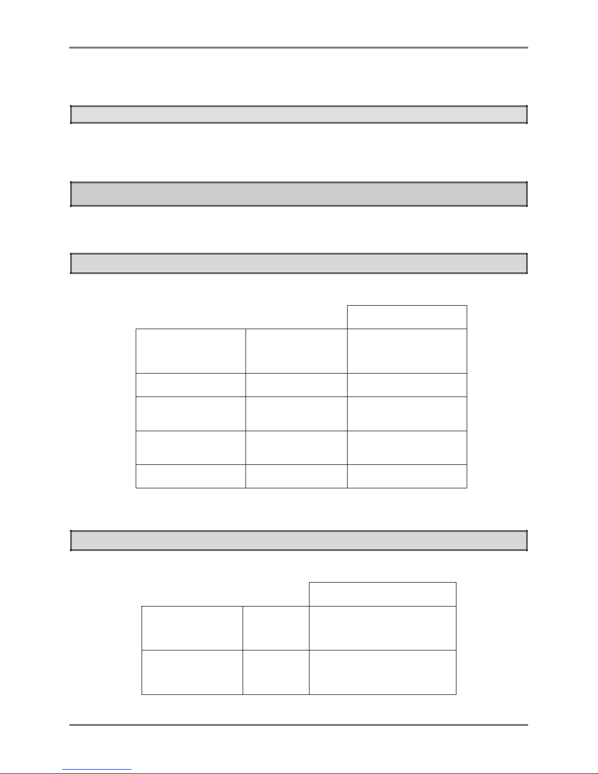
2.1. System Environmental Specifications
Table 2-1. Environmental Specifications
Cactus Technologies
Industrial CFast
Temperature Operating: 0° C to +70° C
(Standard)
-45° C to +90° C
(Extended)
Humidity Operating & Non-
Operating:
Vibration Operating & Non-
Operating:
Shock Operating & Non-
Operating:
Altitude (relative to
sea level)
Operating & Non-
Operating:
8% to 95%, noncondensing
20G, MIL-STD-883G
Method 2005.2,
Condition A
3,000 G, MIL-STD-883G
Method 2002.4,
Condition C
100,000 feet maximum
®
2.2. System Power Requirements
DC Input Voltage
(VCC)
100 mV max.
ripple (p-p)
(Maximum
Average Value)
See Notes.
Cactus Technologies Limited Industrial Grade CFast Card Product Manual v1.1 6
Table 2-2. Power Requirements
Cactus Technologies
Industrial CFast
3.3V ±10%
Sleep:
Reading:
Writing:
210 mA
360 mA
480 mA
®
Page 7
Cactus Technologies, Limited
NOTES: All values quoted are typical at ambient temperature and nominal supply
voltage unless otherwise stated.
Sleep mode is specified under the condition that all drive inputs are static CMOS
levels and in a “Not Busy“ operating state.
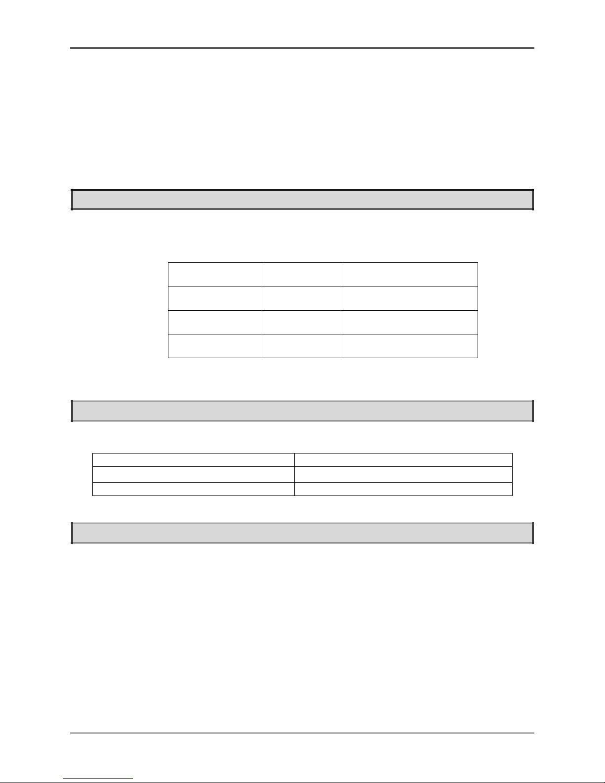
2.3. System Performance
All performance timings assume the drive controller is in the default (i.e., fastest) mode.
Table 2-3. Performance
Start Up Times Reset to ready: 35 msec typical
Read Transfer
Rate
Write Transfer
Rate
Controller
Overhead
.
Command to
Up to 85MBytes/sec
Up to 80 Mbytes/sec
2 msec maximum
DRQ
2.4. System Reliability
Table 2-4. Reliability
MTBF (@ 25°C) > 4,000,000 hours
Data Reliability
Endurance: > 2,000,000 erase/program cycles
< 1 non-recoverable error in 1014 bits READ
2.5. Physical Specifications
The following sections provide the physical specifications for Cactus Technologies
Industrial CFast products.
®
Cactus Technologies Limited Industrial Grade CFast Card Product Manual v1.1 7
Page 8
Cactus Technologies, Limited
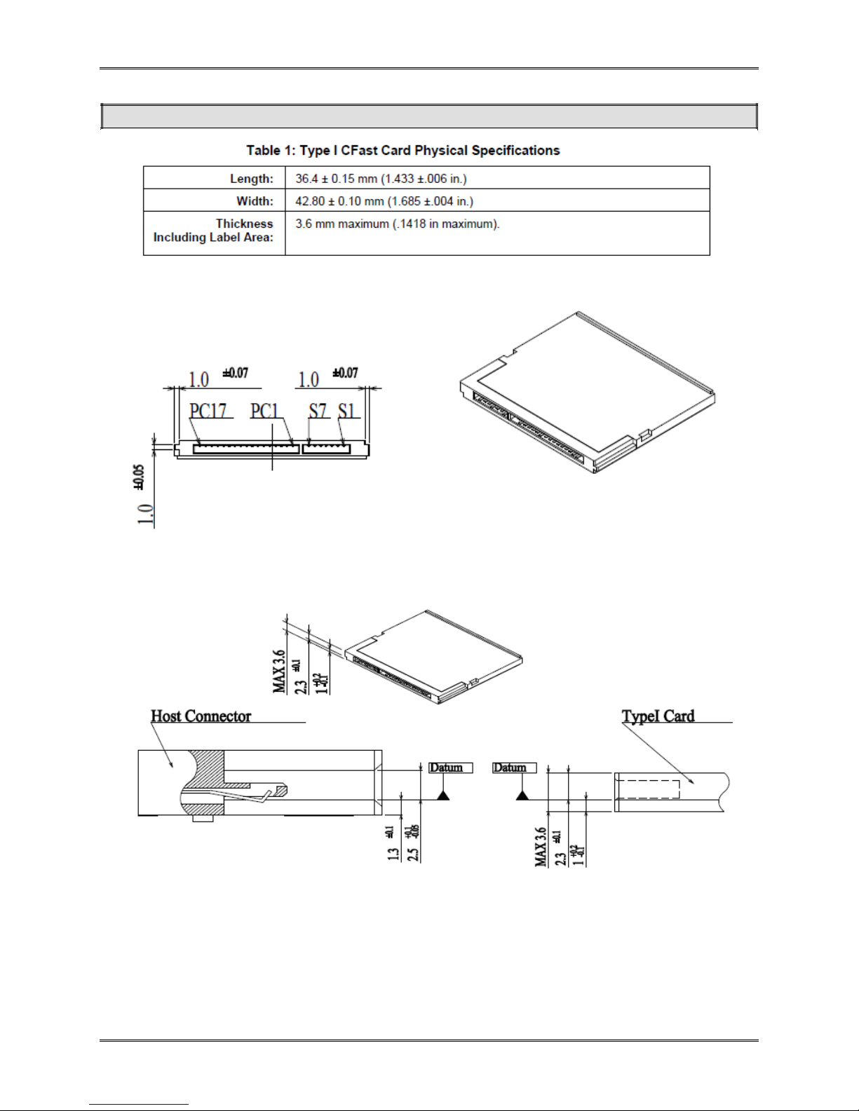
2.5.1. CFast Card Physical Specifications
Cactus Technologies Limited Industrial Grade CFast Card Product Manual v1.1 8
Page 9

Cactus Technologies, Limited
Figure 2-1. Type I CFast Card Dimensions
Cactus Technologies Limited Industrial Grade CFast Card Product Manual v1.1 9
Page 10

Cactus Technologies, Limited
Figure 2-2. Type I CFast Card with Write Protect switch
Cactus Technologies Limited Industrial Grade CFast Card Product Manual v1.1 10
Page 11

Cactus Technologies, Limited
3.nterface Description
The following sections provide detailed information on the Cactus Technologies® Industrial
CFast card interface.
3.1. CFast Pin Assignments and Pin Type
Cactus Technologies® CFast signal pinout conforms to CFA specifications. The signal/pin
assignments and descriptions are listed in Table 3-5.
Table 3-5. CFast Pin Assignments and Pin Type
Cactus Technologies Limited Industrial Grade CFast Card Product Manual v1.1 11
Page 12

Cactus Technologies, Limited
3.1.1. Optional Write Protect Function
For CFast cards with the optional Write Protect switch option, the Write Protect function can
be activated either by using the Write Protect switch or by pulling pin PC10 low. The current
Write Protect status of the card is indicated by pin PC8 as described below:
Pin name Type Description
PC8 Output Write Protect Status; 'Low' : card is in WP
mode, 'High' : card is not in WP mode
PC10 Input Enable/Disable Write Protect; '0' : enable
WP, '1' : disable WP. Note that this pin
function is active only if the WP switch is
not in the WP position.
3.2. Electrical Specifications
The following table defines all D.C. Characteristics for the CFast products. Unless otherwise
stated, conditions are:
Vcc = 3.3V ± 10%
Ta = -45°C to 90°C
3.2.1. Absolute Maximum Ratings
Parameter Symbol MIN MAX Unit
s
Storage Temperature Ts -65 +150
Operating Temperature T
Vcc with respect to GND Vcc -0.3 3.6 V
A
-45 +90
o
C
o
C
3.2.2. DC Characteristics
Parameter Symbol MIN MAX Unit
s
Input Voltage Vin -0.5 Vcc + 0.5 V
Output Voltage Vout -0.3 Vcc + 0.3 V
Input Leakage Current I
Output Leakage Current I
Input/Output Capacitance CI/C
LO
LI
o
-10 10 uA
-10 10 uA
10 pF
Cactus Technologies Limited Industrial Grade CFast Card Product Manual v1.1 12
Page 13

Cactus Technologies, Limited
Parameter Symbol MIN MAX Unit
s
Operating Current
Sleep Mode
Active
I
CC
210
480
mA
3.2.3. AC Characteristics
Cactus Technologies® CFast products conforms to all AC timing requirements as specified in
the CFA specifications. Please refer to that document for details of AC timing for all
operation modes of the device.
4.ATA Drive Register Set Definition and
Protocol
The communication to or from the CFast card is done using FIS. Legacy ATA protocol is
supported by using the legacy mode defined in the SATA specifications. In this mode, the
FIS has defined fields which provide all the necessary ATA task file registers for control and
status information. The Serial ATA interface does not support Primary/Secondary or
Master/Slave configurations. Each SATA channel supports only one SATA device, with the
register selection as defined by the ATA standard.
4.1. ATA Task File Definitions
The following sections describes the usage of the ATA task file registers. Note that the
Alternate Status Register of legacy ATA is not defined for SATA drives.
4.1.1. Data Register
The Data Register is a 16-bit register, and it is used to transfer data blocks between the SSD
data buffer and the Host.
4.1.2. Error Register
This register contains additional information about the source of an error when an error is
indicated in bit 0 of the Status register. The bits are defined as follows:
D7 D6 D5 D4 D3 D2 D1 D0
BBK UNC 0 IDNF 0 ABRT 0 AMNF
Bit 7 (BBK) This bit is set when a Bad Block is detected.
Bit 6 (UNC) This bit is set when an Uncorrectable Error is encountered.
Cactus Technologies Limited Industrial Grade CFast Card Product Manual v1.1 13
Page 14

Cactus Technologies, Limited
Bit 5 This bit is 0.
Bit 4 (IDNF) The requested sector ID is in error or cannot be found.
Bit 3 This bit is 0.
Bit 2 (Abort) This bit is set if the command has been aborted because of a status condition: (Not
Ready, Write Fault, etc.) or when an invalid command has been issued.
Bit 1 This bit is 0.
Bit 0 (AMNF) This bit is set in case of a general error.
4.1.3. Feature Register
This register provides information regarding features of the SSD that the host can utilize.
4.1.4. Sector Count Register
This register contains the number of sectors of data requested to be transferred on a read or
write operation between the host and the SSD. If the value in this register is zero, a count of
256 sectors is specified. If the command was successful, this register is zero at command
completion. If not successfully completed, the register contains the number of sectors that
need to be transferred in order to complete the request.
4.1.5. Sector Number (LBA 7-0) Register
This register contains the starting sector number or bits 7-0 of the Logical Block Address
(LBA) for any SSD data access for the subsequent command.
4.1.6. Cylinder Low (LBA 15-8) Register
This register contains the low order 8 bits of the starting cylinder address or bits 15-8 of the
Logical Block Address.
4.1.7. Cylinder High (LBA 23-16) Register
This register contains the high order bits of the starting cylinder address or bits 23-16 of the
Logical Block Address.
4.1.8. Drive/Head (LBA 27-24) Register
The Drive/Head register is used to select the drive and head. It is also used to select LBA
addressing instead of cylinder/head/sector addressing. The bits are defined as follows:
D7 D6 D5 D4 D3 D2 D1 D0
1 LBA 1 DRV HS3 HS2 HS1 HS0
Bit 7 This bit is set to 1.
Bit 6 LBA is a flag to select either Cylinder/Head/Sector (CHS) or Logical Block Address Mode (LBA).
When LBA=0, Cylinder/Head/Sector mode is selected. When LBA=1, Logical Block Address is
selected. In Logical Block Mode, the Logical Block Address is interpreted as follows:
LBA07-LBA00: Sector Number Register D7-D0.
LBA15-LBA08: Cylinder Low Register D7-D0.
Cactus Technologies Limited Industrial Grade CFast Card Product Manual v1.1 14
Page 15

Cactus Technologies, Limited
LBA23-LBA16: Cylinder High Register D7-D0.
LBA27-LBA24: Drive/Head Register bits HS3-HS0.
Bit 5 This bit is set to 1.
Bit 4 (DRV) DRV is the drive number. This should always be set to 0.
Bit 3 (HS3) When operating in the Cylinder, Head, Sector mode, this is bit 3 of the head number. It
is Bit 27 in the Logical Block Address mode.
Bit 2 (HS2) When operating in the Cylinder, Head, Sector mode, this is bit 2 of the head number. It
is Bit 26 in the Logical Block Address mode.
Bit 1 (HS1) When operating in the Cylinder, Head, Sector mode, this is bit 1 of the head number. It
is Bit 25 in the Logical Block Address mode.
Bit 0 (HS0) When operating in the Cylinder, Head, Sector mode, this is bit 0 of the head number. It
is Bit 24 in the Logical Block Address mode.
4.1.9. Status Registers
These registers return the status when read by the host. Reading the Status register does
clear a pending interrupt while reading the Auxiliary Status register does not. The meaning
of the status bits are described as follows:
D7 D6 D5 D4 D3 D2 D1 D0
BUSY RDY DWF DSC DRQ CORR 0 ERR
Bit 7 (BUSY) The busy bit is set when the device has access to the command buffer and registers
and the host is locked out from accessing the command register and buffer. No other
bits in this register are valid when this bit is set to a 1.
Bit 6 (RDY) RDY indicates whether the device is capable of performing operations requested by
the host. This bit is cleared at power up and remains cleared until the device is ready
to accept a command.
Bit 5 (DWF) This bit, if set, indicates a write fault has occurred.
Bit 4 (DSC) This bit is set when the device is ready.
Bit 3 (DRQ) The Data Request is set when the device requires that information be transferred
either to or from the host through the Data register.
Bit 2 (CORR) This bit is set when a Correctable data error has been encountered and the data has
been corrected. This condition does not terminate a multi-sector read operation.
Bit 1 (IDX) This bit is always set to 0.
Bit 0 (ERR) This bit is set when the previous command has ended in some type of error. The bits in
the Error register contain additional information describing the error.
4.1.10. Device Control Register
This register is used to control the drive interrupt request and to issue an ATA soft reset to
the drive. The bits are defined as follows:
D7 D6 D5 D4 D3 D2 D1 D0
HOB X X X 1 SW Rst -IEn 0
Bit 7 This bit is used in 48-bit addressing mode. When cleared, the host can read the most recently
written values of the Sector Count,Drive/Head and LBA registers. When set, the host will read
the previous written values of these registers. A write to any Command block register will
clear this bit.
Cactus Technologies Limited Industrial Grade CFast Card Product Manual v1.1 15
Page 16

Cactus Technologies, Limited
Bit 6 This bit is an X (Do not care).
Bit 5 This bit is an X (Do not care).
Bit 4 This bit is an X (Do not care).
Bit 3 This bit is ignored by the drive.
Bit 2 (SW Rst)This bit is set to 1 in order to force the drive to perform an AT Disk controller Soft
Reset operation. The drive remains in Reset until this bit is reset to '0'.
Bit 1 (-IEn) The Interrupt Enable bit enables interrupts when the bit is 0. When the bit is 1,
interrupts from the drive are disabled. This bit is set to 0 at power on and Reset.
Bit 0 This bit is ignored by the drive.
4.1.11. Drive Address Register
This register is provided for compatibility with the AT disk drive interface. It is recommended
that this register not be mapped into the host's I/O space because of potential conflicts on
Bit 7. The bits are defined as follows:
D7 D6 D5 D4 D3 D2 D1 D0
X -WTG -HS3 -HS2 -HS1 -HS0 -nDS1 -nDS0
Bit 7 This bit is unknown.
Implementation Note:
Conflicts may occur on the host data bus when this bit is provided by a Floppy Disk Controller
operating at the same addresses as the SSD. Following are some possible solutions to
this problem:
1. Locate the SSD at a non-conflicting address (i.e., Secondary address (377) when a Floppy
Disk Controller is located at the Primary addresses).
2. Do not install a Floppy and a SSD in the system at the same time.
3. Implement a socket adapter that can be programmed to (conditionally) tri-state D7 of I/0
address 3F7/377 when a SSD product is installed and conversely to tri-state D6-D0 of
I/O address 3F7/377 when a floppy controller is installed.
4. Do not use the SSD’s Drive Address register. This may be accomplished by either a) If
possible, program the host adapter to enable only I/O addresses 1F0-1F7, 3F6 (or 170177, 176) to the SSD or b) if provided use an additional Primary/Secondary
configuration in the SSD that does not respond to accesses to I/O locations 3F7 and
377. With either of these implementations, the host software must not attempt to use
information in the Drive Address Register.
Bit 6 (-WTG) This bit is 0 when a write operation is in progress, otherwise, it is 1.
Bit 5 (-HS3) This bit is the negation of bit 3 in the Drive/Head register.
Bit 4 (-HS2) This bit is the negation of bit 2 in the Drive/Head register.
Bit 3 (-HS1) This bit is the negation of bit 1 in the Drive/Head register.
Bit 2 (-HS0) This bit is the negation of bit 0 in the Drive/Head register.
Bit 1 (-nDS1) This bit is 0 when drive 1 is active and selected.
Bit 0 (-nDS0) This bit is 0 when the drive 0 is active and selected.
5.ATA Command Description
This section defines the ATA command set supported by the Cactus Technologies® CFast
card.
Cactus Technologies Limited Industrial Grade CFast Card Product Manual v1.1 16
Page 17

Cactus Technologies, Limited
5.1. ATA Command Set
Table 5-6 summarizes the supported ATA command set .
Table 5-6. ATA Command Set
COMMAND Code FR SC SN CY DH
Check Power Mode E5h or
98h
Execute Drive Diagnostic 90h - - - - Flush Cache E7h - - - - Y
Flush Cache Ext EAh - - - - Y
Identify Drive ECh - - - - D
Idle E3h - Y - - D
Idle Immediate E1h - - - - D
Initialize Drive Parameters 91h - Y - - Y
Read DMA C8h or
C9h
Read DMA Ext 25h - Y Y Y Y
Read FPDMA Queued 60h Y Y Y Y Y
Read Log Ext 2Fh Y Y Y Y Y
Read Multiple C4h - Y Y Y Y
Read Multiple Ext 29h - Y Y Y Y
Read Sector(s) 20h or
21h
Read Sector(s) Ext 24h - Y Y Y Y
Read Verify Sector(s) 40h or
41h
Read Verify Sector(s) Ext 42h - Y Y Y Y
Recalibrate 1Xh - - - - D
Security Disable Password F6h - - - - D
Security Erase Prepare F3h - - - - D
Security Erase Unit F4h - - - - D
Security Freeze Lock F5h - - - - D
Security Set Password F1h - - - - D
Security Unlock F2h - - - - D
Seek 7Xh - - Y Y Y
Set Features EFh Y - - - D
Set Multiple Mode C6h - Y - - D
Set Sleep Mode E6h - - - - D
SMART B0h Y - - Y D
Stand By E2h - - - - D
Stand By Immediate E0h - - - - D
Write DMA CAh or
CBh
Write DMA Ext 35h - Y Y Y Y
Write DMA FUA Ext 3Dh - Y Y Y Y
Write FPDMA Queued 61h Y Y Y Y Y
Write Multiple C5h - Y Y Y Y
- - - - D
- Y Y Y Y
- Y Y Y Y
- Y Y Y Y
- Y Y Y Y
Cactus Technologies Limited Industrial Grade CFast Card Product Manual v1.1 17
Page 18

Cactus Technologies, Limited
COMMAND Code FR SC SN CY DH
Write Multiple Ext 39h - Y Y Y Y
Write Multiple FUA Ext CEh - Y Y Y Y
Write Sector(s) 30h or
31h
Write Sector(s) Ext 34h - Y Y Y Y
Definitions: FR = Features Register, SC = Sector Count Register, SN = Sector Number Register, CY
= Cylinder Registers, DH = Drive/Drive/Head Register.
Y—The register contains a valid parameter for this command. For the Drive/Head Register Y means
both the drive and head parameters are used; D—only the drive parameter is valid and not the
head parameter.
Note: 1. For SATA drives, the drive number is always 0.
- Y Y Y Y
5.1.1. Identify Drive—ECH
The Identify Drive command enables the host to receive parameter information from the
drive. This command has the same protocol as the Read Sector(s) command. The parameter
words in the buffer have the arrangement and meanings defined in Table 5-7. All reserved
bits or words are zero. Table 5-7 is the definition for each field in the Identify Drive
Information.
Table 5-7. Identify Drive Information
Word
Address
0 0040H 2 General configuration bit-significant information.
1 XXXXH 2 Default number of cylinders; capacity dependent.
2 C837H 2 Reserved.
3 00XXH 2 Default number of heads; capacity dependent.
4 XXXXH 2 Number of unformatted bytes per track.
5 XXXXH 2 Number of unformatted bytes per sector.
6 XXXXH 2 Default number of sectors per track; capacity dependent.
7-8 XXXXH,XXX
9 000EH 2 Reserved.
10-19 aaaa 20 Serial number in ASCII (Right Justified).
20 XXXXH 2 Retired
21 XXXXH 2 Retired
22 0003FH 2 Obsolete
23-26 aaaa 8 Firmware revision in ASCII . Big Endian Byte Order in Word.
27-46 aaaa 40 Model number in ASCII (Left Justified) Big Endian Byte Order
47 8001H 2 Maximum number of sectors on Read/Write Multiple
48 4000H 2 Double Word not supported.
49 2F00H 2 Capabilities: DMA Supported (bit 8), LBA supported (bit 9).
50 4000H 2 Reserved.
51 0280H 2 PIO data transfer cycle timing mode
52 0000H 2 Single Word DMA data transfer cycle timing mode (not
53 0007H 2 Data fields 54-58,64-70 and 88 are valid.
54 XXXX 2 Current numbers of cylinders.
Default
Value
XH
Total
Bytes
4 Number of sectors per drive (Word 7 = MSW, Word 8 =
LSW); capacity dependent.
in Word.
command
supported).
Data Field Type Information
Cactus Technologies Limited Industrial Grade CFast Card Product Manual v1.1 18
Page 19

Cactus Technologies, Limited
Word
Address
Default
Value
Total
Bytes
Data Field Type Information
55 00XX 2 Current numbers of heads.
56 XXXX 2 Current sectors per track.
57-58 XXXX 4 Current capacity in sectors (LBAs) (Word 57 = LSW, Word 58
= MSW).
59 0000H 2 Multiple sector setting is valid; low byte is capacity
dependent.
60-61 XXXX 4 Total number of sectors addressable in LBA Mode.
62 0000H 2 Reserved
Multiword DMA modes 0-2 are supported; upper byte
63 0007H 2
64 0003H
2
reflects currently selected MWDMA mode.
Advanced PIO modes supported (modes 3 and 4)
65 0078H 2 Minimum MWDMA cycle time per word is 120ns.
66 0078H 2 Recommended MWDMA cycle time is 120ns.
67 0078H 2 Minimum PIO cycle time without IORDY flow control is 120ns.
68 0078H 2 Minimum PIO cycle time with IORDY flow control is 120ns.
69-74 0000H 10 Reserved
75 0000H 2 Queue depth of 1
76 0106H 2 Supports SATA NCQ, Gen 1, Gen2 signaling rates
77 0000H 2 Reserved
78 0004H 2 Supports DMA Setup Auto-Activate optimization
79 0000H 2 Status of word 78 features
80 01FEH 2 Supports ATA7 standard.
81 0021H 2 No minor revision reported.
82
83
84
0069H
2
7400H
2
4060H
2
PACKET Command, Security Mode feature sets not
supported; SMART feature supported
48-bit mode supported; Flush Cache/Flush Cache Ext
supported.
WRITE DMA FUA EXT and WRITE MULTIPLE FUA EXT
supported
85 XXXXH 2 Feature status
86 XXXXH 2 Feature status
87 XXXXH 2 Feature status
88 203FH 2 UDMA Modes 0-5 supported.
89-91 0000H 6 Reserved
92 XXXXH 2 Master password revision code
93 XXXXH 2 COMRESET result
94 80FEH 2 Acoustic management values
95-99 0000H 10 Reserved
100-103 XXXXH 8 Maximum user LBA for 48-bit addressing mode.
104-127 0000H 48 Reserved
128 XXXXH 2 Security status
129-255 - Reserved
Cactus Technologies Limited Industrial Grade CFast Card Product Manual v1.1 19
Page 20

Cactus Technologies, Limited
Appendix A. Ordering Information
Model KCXFYT-602S-WP
Where: X is drive capacities:
1G ---------------- 1GB
2G ---------------- 2GB
4G ---------------- 4GB
8G ---------------- 8GB
16G -------------- 16GB
32G -------------- 32GB
Where Y is temperature:
Blank --------------- Standard temperature (0° C to +70° C)
I --------------------- Extended temperature (-45° C to +90° C)
Where T is memory type:
Blank -------------- Samsung
T -------------------- Toshiba (only for 16 & 32GB)
Where -WP is Write Protect option:
Blank -------------- no Write Protect
-WP ----------------- with Write Protect switch
Example:
(1) 8GB CFast ---------------------------------------------------------- KC8GF-602S
(2) 8GB CFast Extended Temp ----------------------------------- KC8GFI-602S
(3) 32GB CFast -------------------------------------------------------- KC32GFT-602S
(4) 8GB CFast with Write Protect --------------------------------- KC8GF-602S-WP
Cactus Technologies Limited Industrial Grade CFast Card Product Manual v1.1 20
Page 21

Cactus Technologies, Limited
Appendix B.Technical Support Services
B.1.Direct Cactus Technologies® Technical Support
Cactus Technologies Limited
Suite C, 15/F, Capital Trade Center
62 Tsun Yip Street, Kwun Tong
Kowloon, Hong Kong
Tel: +852-27972261
Fax: +852-27973777
Email: tech@cactus-tech.com
Cactus Technologies Limited Industrial Grade CFast Card Product Manual v1.1 21
Page 22

Cactus Technologies, Limited
Appendix C.Cactus Technologies® Worldwide Sales
Offices
Cactus Technologies Limited
Suite C, 15/F, Capital Trade Center
62 Tsun Yip Street, Kwun Tong
Kowloon, Hong Kong
Tel: +852-27972277
Fax: +852-27973777
Email: sales@cactus-tech.com
Cactus Technologies Limited Industrial Grade CFast Card Product Manual v1.1 22
Page 23

Appendix D.Limited Warranty
I. WARRANTY STATEMENT
Cactus Technologies® warrants its Industrial Grade products only to be free of any defects in
materials or workmanship that would prevent them from functioning properly for five years
from the date of purchase. This express warranty is extended by Cactus Technologies
Limited to customers of our products.
II. GENERAL PROVISIONS
This warranty sets forth the full extent of Cactus Technologies® responsibilities regarding
the Cactus Technologies® Industrial Grade Flash Storage Products. Cactus Technologies®, at
its sole option, will repair, replace or refund the purchase price of the defective product.
Cactus Technologies® guarantees our products meet all specifications detailed in our
product manuals. Although Cactus Technologies® products are designed to withstand harsh
environments and have the highest specifications in the industry, they are not warranted to
never have failure and Cactus Technologies® does not warranty against incidental or
consequential damages. Accordingly, in any use of products in life support systems or other
applications where failure could cause injury or loss of life, the products should only be
incorporated in systems designed with appropriate redundancy, fault tolerant or backup
features.
®
III. WHAT THIS WARRANTY COVERS
For products found to be defective within five years of purchase, Cactus Technologies® will
have the option of repairing, replacing or refunding the purchase price the defective
product, if the following conditions are met:
A. The defective product is returned to Cactus Technologies® for failure analysis as soon as
possible after the failure occurs.
B. An incident card filled out by the user, explaining the conditions of usage and the nature
of the failure, accompanies each returned defective product.
C. No evidence is found of abuse or operation of products not in accordance with the
published specifications, or of exceeding maximum ratings or operating conditions.
All failing products returned to Cactus Technologies® under the provisions of this limited
warranty shall be tested to the product’s functional and performance specifications. Upon
confirmation of failure, each product will be analyzed, by whatever means necessary, to
determine the root cause of failure. If the root cause of failure is found to be not covered by
the above provisions, then the product will be returned to the customer with a report
indicating why the failure was not covered under the warranty.
This warranty does not cover defects, malfunctions, performance failures or damages to the
unit resulting from use in other than its normal and customary manner, misuse, accident or
neglect; or improper alterations or repairs. Cactus Technologies® Limited may repair or
replace, at its discretion, any product returned by its customers, even if such product is not
covered under warranty, but is under no obligation to do so.
Cactus Technologies Limited Industrial Grade CFast Card Product Manual v1.1 23
Page 24

IV. RECEIVING WARRANTY SERVICE
According to Cactus Technologies® warranty procedure, defective product should be
returned only with prior authorization from Cactus Technologies® Limited. Please contact
Cactus Technologies® Customer Service department (tech@cactus-tech.com) with the
following information: product model number and description, nature of defect, conditions of
use, proof of purchase and purchase date. If approved, Cactus Technologies® will issue a
Return Material Authorization or Product Repair Authorization number. Ship the defective
product to:
Cactus Technologies Limited
Suite C, 15/F, Capital Trade Center
62 Tsun Yip Street, Kwun Tong
Kowloon, Hong Kong
Cactus Technologies Limited Industrial Grade CFast Card Product Manual v1.1 24
 Loading...