

Page 1

Gigabit Ethernet Packet Capture
User’s Guide
Page 2

Copyrights
Copyright © 2008 CACE Technologies, Inc.
All rights reserved.
This document may not, in whole or part, be: copied; photocopied; reproduced; translated; reduced; or
transferred to any electronic medium or machine-readable form without prior consent in writing from
CACE Technologies, Inc.
TurboCap
Gigabit Ethernet Packet Capture
User’s Guide
Document Version: 1.0
Document Revision: June 2008
CACE Technologies, Inc.
Davis, CA 95616
(530) 758-2790
(530) 758-2781 (fax)
support@cacetech.com
http://www.cacetech.com
Page 3

Contents
Contents and Figures
TurboCap .......................................................................................................3
Overview of TurboCap..................................................................................4
Terminology.............................................................................................4
Overall Description..................................................................................4
Feature Description .......................................................................................5
Concurrent capture and injection.............................................................5
Packet timestamps....................................................................................5
Dual Port Pass-thru ..................................................................................6
Multiple Port Aggregation.......................................................................7
Packet injection scheduling .....................................................................7
Link speed and auto-negotiation..............................................................7
Packet meta-information..........................................................................8
Support for multiple boards within the same PC ....................................8
Error packets ............................................................................................9
Packet snapshot........................................................................................9
Filtering ....................................................................................................9
FCS...........................................................................................................9
Support for jumbo frames......................................................................10
LED functionality ..................................................................................10
Link status ..............................................................................................10
VLAN support........................................................................................10
Statistics .................................................................................................10
Configuring TurboCap: the TurboCap Control Panel................................12
Dump-to-Disk Utility ..................................................................................15
TurboCap and Wireshark ............................................................................16
Identifying the TurboCap Ports and Boards in Wireshark ...................16
Wireshark Capture Options and the PPI Header...................................16
The TurboCap API and Developer’s Pack .................................................18
Recommended HW and Software Platforms..............................................19
Where to Learn More..................................................................................20
i
Page 4

Figures
Figure 1 - TurboCap Modules.......................................................................4
Figure 2 - Dual Port Pass-thru.......................................................................6
Figure 3 - The TurboCap Control Panel.....................................................12
Figure 4 - Pass-thru Mode...........................................................................13
Figure 5 - Editing Port Names.....................................................................13
Figure 6 - TurboCap Command Prompt .....................................................15
Figure 7: The Wireshark Adapters List ......................................................16
Figure 8 – Per-Packet Information Header (PPI)........................................16
Figure 9 – PPI Fields...................................................................................17
Figure 10. TurboCap API Online Documentation......................................18
ii TurboCap User’s Guide
Page 5

TurboCap
CACE Technologies’ TurboCap is feature-rich, dual-port Gigabit Ethernet
packet capture and injection solution with advanced features such as
simultaneous full-rate capture and injection, multiport traffic aggregation,
and a configurable pass-thru mode. Wireshark integration supports packet
capture using TurboCap interfaces and off-line analysis of TurboCap
capture files. A native TurboCap API and a WinPcap API are available
for writing/porting your own Gigabit Ethernet applications. TurboCap
includes a PCI Express, Dual-Port, Gigabit Ethernet Board, the TurboCap
optimized Windows driver, and user-level API interfaces.
PRODUCT FEATURES
Full-Rate Gigabit Ethernet Capture. TurboCap supports simultaneous
full-rate Gigabit caputure on both ports with precise timestamps and perpacket meta information. The TurboCap Windows driver has support for
multiple TurboCap boards.
Board (Port) Aggregation. TurboCap supports full-rate aggregation of
the traffic received on both ports of the same board.
Dual Port Pass-thru Mode. TurboCap supports a full-rate pass-thru
mode in which packets received on each port are injected out the other port
of the same board, similar to a hardware tap.
Aggregating Tap. The combination of Board Aggregation and Pass-thru
Mode provides the functionality of a hardware aggregating tap.
Full-Speed Gigabit Ethernet Injection. TurboCap supports
simultaneous full-rate Gigabit packet injection on both ports. Packets are
transmitted in the order in which they are sent to the driver and with
minimal delay.
Wireshark and WinPcap Compatible. Wireshark can be used to capture
on all of the TurboCap interfaces including the aggregating ports and
capture files obtained using the TurboCap dump-to-disk application can be
opened and analyzed using Wireshark. TurboCap is integrated with
WinPcap and, consequently, supports other open-source applications that
use the WinPcap API, such as Windump and Ntop.
3
Page 6
Overview of TurboCap
Terminology
Board: a PCI-Express Intel network card.
Port: one of the two Ethernet connectors on a board. The two ports are
called port A and port B.
Packet: a unit of data transmitted or received on the physical Ethernet
cable. A packet is defined as starting from the Ethernet header (the first
field is the MAC destination address) and up to and including the Ethernet
Frame Check Sequence field (FCS).
Overall Description
TurboCap is a solution for packet capture and packet injection that runs on
a standard Windows-based machine. TurboCap includes three main
components, shown in Figure 1:
TurboCap
TurboCap
TurboCap
Wireshark
Wireshark
Wireshark
Wireshark
WinPcap
WinPcap
WinPcap
WinPcap
TurboCap
TurboCap
TurboCap
TurboCap
user API
user API
user API
user API
TurboCap
TurboCap
TurboCap Driver
TurboCap Driver
TurboCap Driver
TurboCap Driver
TurboCap Board
TurboCap Board
TurboCap Board
TurboCap Board
Gigabit
Gigabit
Ethernet Port
Ethernet Port
Figure 1 - TurboCap Modules
TurboCap
Native application
Native application
Native application
Native application
Kernel mode
Kernel mode
Gigabit
Gigabit
Ethernet Port
Ethernet Port
User mode
User mode
- A Dual Port Gigabit Ethernet Board, named TurboCap Board.
- A custom Windows driver (TurboCap Driver).
- A user level API (TurboCap user API). The API allows writing
custom sniffing and packet injection tools, as well as using existing
4 TurboCap User’s Guide
Page 7

Feature Description
applications based on WinPcap (Through a custom modification of the
WinPcap DLLs)
TurboCap supports receiving and transmitting packets from each of the
ports of a board.
In the following paragraphs, in order to distinguish the features typical of
reception from the ones of transmission, we use the terms capture (when
the feature is related to reception) and injection (when the feature is related
to transmission).
When we talk about capture, we mean that TurboCap receives all the
packets from the Ethernet cable attached to a port of the board and
delivers such packets to an application running on top of TurboCap.
When we talk about injection, we mean that TurboCap receives packets
from an application and transmits them on a specific port of the board.
Concurrent capture and injection
TurboCap can
- Capture and inject concurrently on the same port of a board.
- Capture concurrently on the two ports of a board.
- Inject concurrently on the two ports of a board.
- All the possible combinations of the above.
Packet timestamps
Capture
Each received packet is delivered with a timestamp attached to it.
The timestamp corresponds to the moment when the reception of the
packet completed, i.e. when the last byte of the packet was received.
The timestamp is represented as a 64 bit unsigned integer value,
representing the number of nanoseconds since the midnight Coordinated
Universal Time (UTC) of January 1, 1970.
Three timestamping modes are available:
- OFF: timestamps are not generated and the timestamp field in the
packet meta-information (if available) is set to 0.
- ON (polling mode): timestamps are generated by the TurboCap
TurboCap User’s Guide 5
Page 8

software as soon as the BOARD completes the copy of the packet into
the PC memory and the software detects that packet is available. This
timestamping mode has the following characteristics:
o More accurate timestamps are generated
o It causes a high CPU usage as 1 CPU is running a busy-wait
loop to timestamp the packets.
- ON (timer mode): timestamps are generated by the TurboCap software
as soon as the BOARD completes the copy of the packet into the PC
memory and the software detects that packet is available. Differently
from the “ON (polling mode)”, timestamps are generated periodically
by the TurboCap using a 1ms precise timer. This timestamping mode
has the following characteristics:
o Less accurate timestamps are generated
o Low impact on the CPU usage.
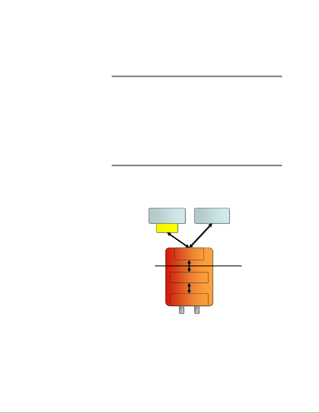
Dual Port Pass-thru
Each board can be configured to inject the traffic received from one port
to the other port of the same board (see Figure 2).
TurboCap
TurboCap
TurboCap
TurboCap
user API
user API
user API
user API
User mode
User mode
TurboCap
Switch B
Switch B
Switch B
Switch B
TurboCap
TurboCap Driver
TurboCap Driver
TurboCap Driver
TurboCap Driver
Gigabit
Gigabit
Ethernet Port
Ethernet Port
TurboCap Board
TurboCap Board
TurboCap Board
TurboCap Board
x
x
Ethernet Port
Ethernet Port
Gigabit
Gigabit
Kernel mode
Kernel mode
Switch B
Switch B
Switch B
Switch B
Figure 2 - Dual Port Pass-thru
Dual Port Pass-thru is a per-board feature. Different boards on the same
PC can have different Dual Port Pass-thru settings.
When Dual Port Pass-thru is ON, the packets received on port A are
transmitted out on port B and the packets received on port B are
transmitted out on port A. It’s not possible to selectively enable and
disable the pass-thru functionality in a single direction (i.e. it’s not
possible to have AB enabled and BA disabled).
Dual Port Pass-thru is not available on ports belonging to different boards.
When Dual Port Pass-thru is ON, TurboCap does not support traffic
injection on the pass-thru’ed ports.
6 TurboCap User’s Guide
Page 9

The Dual Port Pass-thru acts as a Network Tap, but from the network point
of view it acts as a bridge, not as repeater (i.e. it works at L2).
Multiple Port Aggregation
Each board exposes a virtual port that aggregates the traffic received on
the two ports of a board into one single capture stream of packets. This
virtual port is called Board Aggregating Port (BAP).
A BAP is a per-board feature. Each board on a PC exposes a different
BAP with its own settings.
TurboCap also exposes a virtual port that aggregates the traffic received
from all the ports of all the boards on the system into a single capture
stream of packets. This virtual port is called TurboCap Aggregating Port
(TcAP). There is one single TcAP per machine mounting at least one
TurboCap board.
When capturing from a BAP or TcAP virtual port, the TurboCap based
application will receive the packets captured from all the ports of a board
(in the case of BAP) or from all the ports in the system (in the case of
TcAP) on a single open instance.
TurboCap does not support traffic injection on the BAPs and TcAPs.
Packet injection scheduling
Injection
TurboCap is able to inject packets with a best-effort approach, i.e. packets
are transmitted as soon as possible (respecting the minimum inter-frame
gaps imposed by the 802.3 standards).
Link speed and auto-negotiation
TurboCap supports the following link speeds:
- 10Mbps full duplex (10BASE-T)
- 10Mbps half duplex (10BASE-T)1
- 100Mbps full duplex (100BASE-TX)
- 100Mbps half duplex (100BASE-TX)1
- 1Gbps full duplex (1000BASE-T)
1
Reception only
TurboCap User’s Guide 7
Page 10

Auto-negotiation is always enabled.
You can change the link speeds negotiated during auto-negotiation on a
port basis (the two ports of a board have separate settings).
When operating in pass-thru mode, you must set the negotiated link speeds
to the same setting.
Independently from the auto-negotiation setting, TurboCap can return the
current auto-negotiation and link speed of a port at any moment in time.
Packet meta-information
Capture
When a packet is received with TurboCap, a set of packet metainformation is delivered with the packet.
The packet meta-information contains the following information:
- Length of the original packet
- Number of bytes that have been captured from the packet. This can be
less than the length of the original packet, and is user configurable.
- Timestamp (1ns resolution).
- Flags indicating if
o The packet was received correctly by the board or not.
o In case of error, it reports which kind of error occurred.
o Presence of the Frame Check Sequence (FCS) at the end of
the packet.
o An ID of the port on which the packet was received (this is
used in conjunction with aggregating ports, BAP and TcAP)
Injection
When a packet needs to be transmitted with TurboCap, a set of packet
meta-information should be delivered with the packet to the TurboCap
software.
The packet meta-information must contain the following information:
- Length of the packet to be transmitted.
- Presence of the Frame Check Sequence (FCS) at the end of the packet.
Support for multiple boards within the same PC
TurboCap supports one or more boards running at the same time on a
single PC.
8 TurboCap User’s Guide
Page 11

Error packets
Capture
TurboCap is able to capture packets with the following errors:
- wrong frame check sequence (FCS)
- physical errors.
TurboCap is able to notify the user when the packet is correct, has an
error, and which kind of error has been detected in the reception of the
packet.
TurboCap has a setting to disable the reception of error packets. This
setting is per port.
Packet snapshot
Capture
The board is able to capture a subset, “snapshot”, of each packet. The
setting is called snaplen, Snapshot Length. TurboCap allows to set the
snaplen and to retrieve the current snaplen.
Filtering
Capture
The first version of TurboCap does not have any built-in hardware (i.e. on
the board) or driver-level (i.e. in the TurboCap driver) packet filtering
capability. BPF packet filters are applied at user level in the WinPcap
libraries when interfaced with the TurboCap user API.
The only available built-in hardware filter is related to error vs. correct
packets.
FCS
Capture
TurboCap returns the Frame Check Sequence of every captured packet,
even if the FCS is wrong. TurboCap captures packets with both correct
and wrong frame check sequence.
TurboCap allows capturing all the packets (correct and with wrong FCS)
as well as filtering out the wrong ones.
TurboCap User’s Guide 9
Page 12

Injection
TurboCap allows injecting packets with correct FCS and wrong FCS. The
user application can choose to be responsible for computing the FCS of
every injected packet, or let the TurboCap board compute the FCS for the
injected packets. In case TurboCap computes the FCS, it will always
compute a valid FCS (i.e. it cannot generate wrong FCS values).
Support for jumbo frames
Capture and Injection
TurboCap supports a maximum packet size of 9234 bytes (including the
trailing FCS), both for capture and injection.
LED functionality
Each port of a board ships with 2 multicolor LEDs
(off/green/yellow/orange), that can be either controlled by the TurboCap
API or connected to a board source like “link is up at 10/100/1000”.
Link status
TurboCap can notify when the link goes up or down on a per port basis.
It’s also possible to query TurboCap for the link status on a per port basis
directly.
VLAN support
Capture and Injection
TurboCap fully supports reception and injection of VLAN tagged frames.
Statistics
TurboCap is able to return a series of statistics related to packet capture
and injection. Unless otherwise noted, all the statistics are represented as
64bit unsigned integers.
Capture
- Total received packets (per port and per open instance)
- Total received bytes (per port and per open instance)
- Packets received with errors (per port and per open instance)
10 TurboCap User’s Guide
Page 13

- Packets received correctly (per port and per open instance)
- Dropped packets due to low hardware resources.
Injection
- Total sent packets (per port and per open instance)
- Total sent bytes (per port and per open instance).
TurboCap User’s Guide 11
Page 14
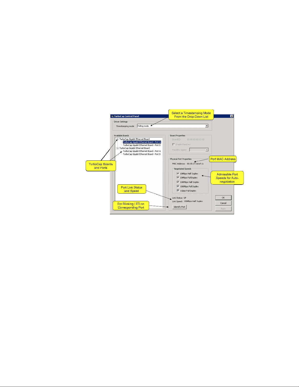
Configuring TurboCap: the TurboCap Control Panel
The TurboCap control panel (Figure 3) provides a convenient and intuitive
way to configure the parameters of currently-connected TurboCap boards.
The changes made to an adapter using the TurboCap control panel will be
reflected in all of the applications using that adapter.
To start the TurboCap control panel, click on
START→ALL PROGRAMS→TurboCap→TurboCap Control Panel
Figure 3 - The TurboCap Control Panel
Referring to Figure 3, the Available Boards box contains a list of the
available TurboCap boards on the system and Ports A and B for each
board. Port A of the first board has been selected.
The MAC Address for the selected port is shown in the Physical Port
Properties box.
TurboCap autonegotiates link speeds for each port. The autonegotiated
speeds are chosen from the selected port speeds. Each port can have a
different set of negotiated speeds.
Link Status (Up or Down) and Link Speed are also shown for the selected
port. Finally, it is possible to cause an LED on the port to blink by
clicking on Identify Port. In this manner you can associate a particular
physical port with the name of the port in the control panel. This will also
help to identify the board itself.
The Driver Settings box offers a range of timestamping modes which trade
timestamp accuracy for CPU utilization. You have the option of choosing
12 TurboCap User’s Guide
Page 15
the timestamp mode that best suits your needs, from highly accurate
timestamps to no timestamp generation.
Polling Mode. In this mode, a CPU polls for packet arrivals and
timestamps the packet as soon as it is available from the board. These
timestamps are very accurate (microsecond accuracy) but require a CPU to
be running in a busy wait loop.
Timer Mode. Timer mode uses a 1ms timer to periodically timestamp
incoming packets. This puts very little load on the CPU and provides
timestamps with millisecond accuracy.
Off. In this case, no timestamps are generated and the timestamp fields in
the packet meta-information are set to zero.
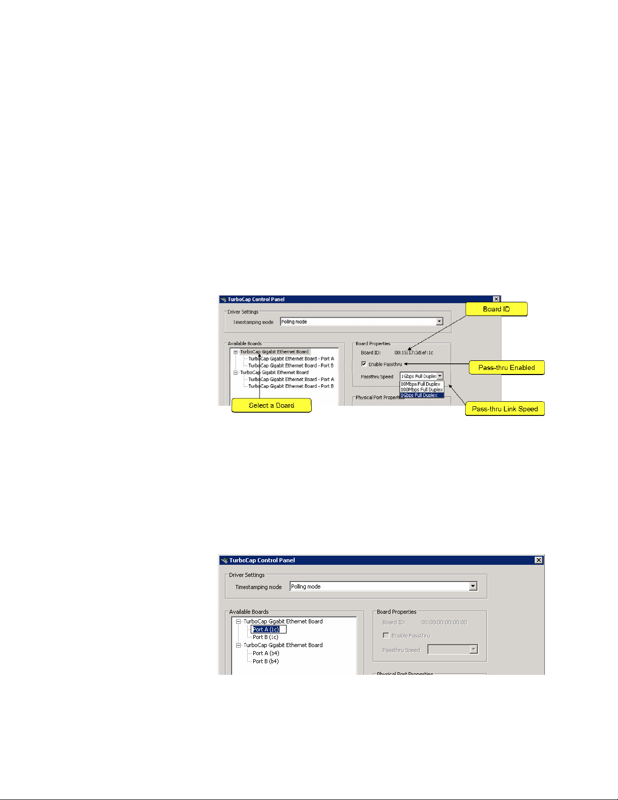
Figure 4 - Pass-thru Mode
In Figure 4 the first board is selected in the Available Boards box. The
Board ID is shown in the Board Properties box and corresponds to the
MAC address of Port A and is used for identification purposes only.
When Pass-thru is enabled, it is important that the negotiated link speeds
on both ports are identical. The pass-thru speed is selected from the dropdown list.
Figure 5 - Editing Port Names
TurboCap User’s Guide 13
Page 16

It is also possible to use the control panel to change the names of the
TurboCap Ports. For example, Figure 5 shows Port A highlighted for
editing to shorten the overall name and to add “1c” in parentheses thereby
identifying the Port name with the last two digits of the corresponding
Board ID (see Figure 4).
14 TurboCap User’s Guide
Page 17
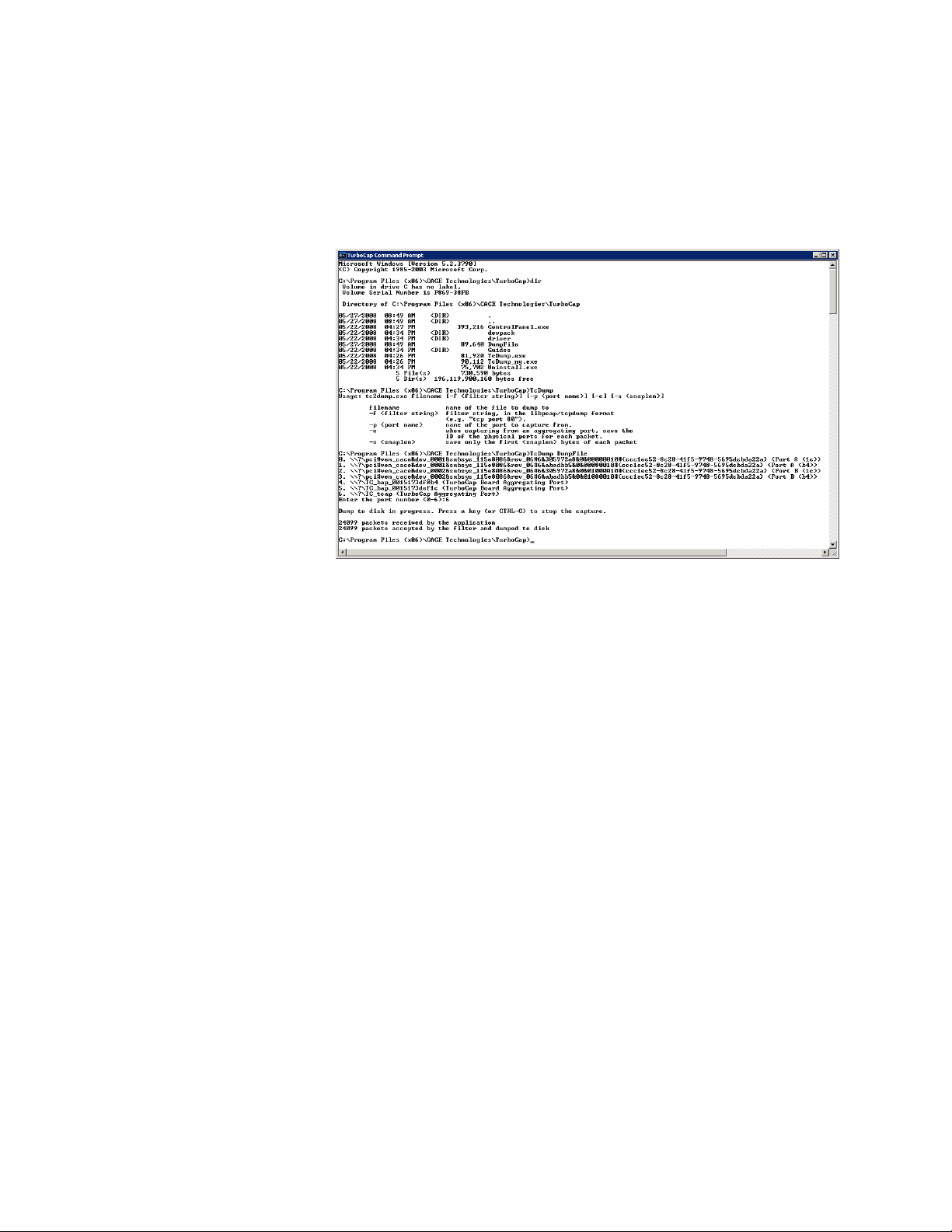
Dump-to-Disk Utility
In this section we describe the functionality of the TurboCap utility for
high-speed capture to disk. To start the TurboCap control panel, click on
START→ALL PROGRAMS→TurboCap→TurboCap Command Prompt
Figure 6 - TurboCap Command Prompt
Once the command window opens you can type “dir” to see the contents
of the command prompt directory shown in Figure 6. It includes the
Control Panel executable, the developer’s pack directory, the TurboCap
driver directory, the Guides directory (contains the Installation Guide and
this Guide), and two dump-to-disk executables (TcDump.exe and
TxDump_ng.exe), and finally, the Uninstall executable.
Also shown in Figure 6 is the “help” output of TcDump when run without
arguments.
Finally, TcDump is run with “DumpFile” as the name of the dump file.
We see that TcDump lists the TurboCap capture ports and asks for a
number to identify the port. You will notice that the Port name changes
we made using the Control Panel appear at the right-hand of the Port list.
Also, the Board IDs appear for identification of the Board Aggregating
Ports.
TurboCap User’s Guide 15
Page 18

TurboCap and Wireshark
Wireshark is completely integrated with TurboCap thereby giving you the
opportunity to use a familiar too for analyzing TurboCap sources.
Identifying the TurboCap Ports and Boards in Wireshark
Figure 7 shows the Wireshark Capture Interfaces dialog
(Capture→Interfaces). The TurboCap Ports are easily identified by the
names we assigned to them using the TurboCap control panel.
Figure 7: The Wireshark Adapters List
The interface panel (Figure 7 shows the two TurboCap Board Aggregating
Ports. Since only one of the Boards is attached to a traffic source, it is
easy to identify which board corresponds to each Board Aggregating Port.
Wireshark Capture Options and the PPI Header
Figure 8 – Per-Packet Information Header (PPI)
16 TurboCap User’s Guide
Page 19

The Capture Options panel (Figure 8) has been modified to include a dropdown box with two options: Ethernet and Per-Packet Information header.
Figure 9 – PPI Fields
In Figure 9 we show the middle panel of the Wireshark 3-panel viewer
with the PPI field fully expanded. The Aggregation Extension field
contains the interface ID which enables you to distinguish packets coming
from the two ports of the same board when board aggregation is used.
TurboCap User’s Guide 17
Page 20

The TurboCap API and Developer’s Pack
In this section we provide an overview of the TurboCap API and
developer’s pack.
Figure 10. TurboCap API Online Documentation
The TurboCap API provides direct access to native TurboCap
functionality allowing you to write your own Gigabit Ethernet packet
capture and injection applications. In Figure 10 we show the main page of
the TurboCap online documentation. This documentation provides all of
the information needed to start developing your own TurboCap
applications and includes some sample TurboCap programs that can be
used as starting points for your development.
18 TurboCap User’s Guide
Page 21

Recommended HW and Software Platforms
The TurboCap capture board and Windows driver are only two of the
componenets that determine the overall capture performance of your
system. In order to achieve maximum performance, we recommend the
following minimum hardware requirements.
Hardware
- Host Interface: The TurboCap board requires either a x4 or x8 PCIe
slots with 4 lanes available for the TurboCap board
- CPUs: Pentium-D (dual core) processor or multiple CPUs (SMP), 2.8
GHz
- Memory: minimum of 2 GB RAM
- Disk (Installation): 50MB free disk space on the hard drive plus
additional space for capture (trace) files. Disk performance is key to
full-rate packet dump to disk.
- Disk (Trace files): Full-rate dump-to-disk requires disk arrays that
have sufficient capacity and speed to keep up with full-rate Gigabit
Ethernet. Disk capacity and speed can be achieved using highly
parallel disk arrays.
Software
- TurboCap OS support includes Windows XP and Vista (32 and 64-bit
AMD64).
TurboCap User’s Guide 19
Page 22

Where to Learn More
The best sources of information about the Wireshark network analyzer are:
• The documentation page on the Wireshark website,
http://www.wireshark.org/docs/. From here you can download the
User’s Guide, the man pages, and the developer’s manuals.
• The Wireshark wiki, http://wiki.wireshark.org/.
• The Wireshark mailing lists, http://www.wireshark.org/lists/.
• Wireshark University, http://www.wiresharku.com. WSU features
Laura Chappell, regarded by many as the best protocol analysis trainer
in the world.
If you are a developer, the best sources of information are:
• The TurboCap developer's pack is downloadable from
http://www.cacetech.com/support/downloads.htm and is also available
on the TurboCap Software Distribution CD. The TurboCap
developer's pack contains all the components you need to create
capture applications, including LIB and header files, an online API
documentation and a set of ready-to-compile example programs.
• The WinPcap developer resources page,
http://www.winpcap.org/devel.htm, where you can download the
WinPcap source code and developer’s pack.
20 TurboCap User’s Guide
 Loading...