

cabstone CAB WH EASYSCOPE M 51929, CAB WH EASYSCOPE L 51936, CAB WH EASYSCOPE M 51928, CAB WH EASYSCOPE L 51937, CAB WH EASYSCOPE XL 51942 User Manual
...
TM
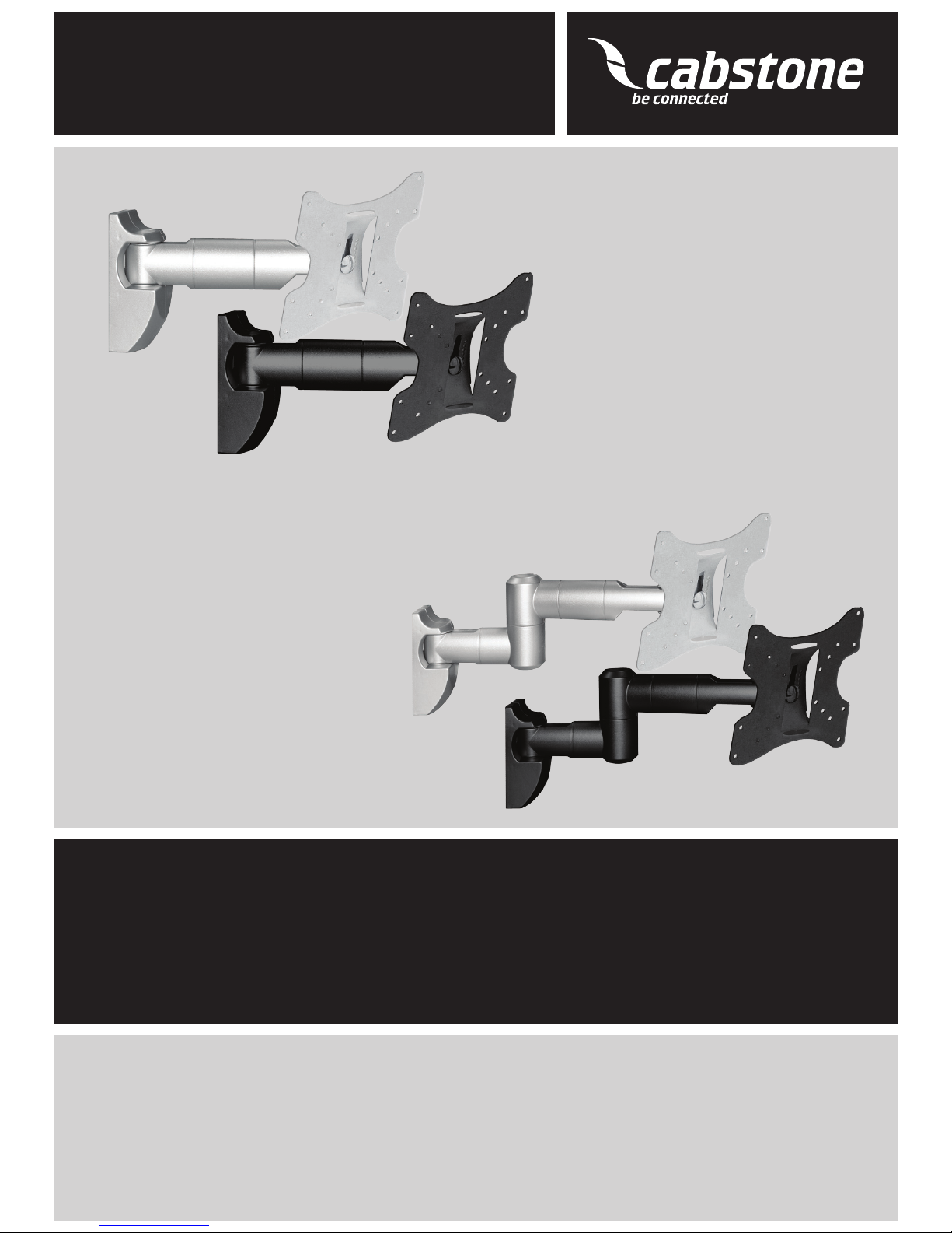
TV EASYSCOPE M / MULTI
CAB WH EASYSCOPE M 25-74 CM (10 - 30“) SILBER / silver 51928
CAB WH EASYSCOPE M 25-74 CM (10 - 30“) SCHWARZ / black 51929
CAB WH EASYSCOPE MULTI 25-74 CM (10 - 30“) SILBER / silver 51930
CAB WH EASYSCOPE MULTI 25-74 CM (10 - 30“) SCHWARZ / black 51931
Bedienungsanleitung
Manual
Notice d’utilisation
Manual
Istruzioni per l’uso
Bruksanvisning
Manual
Οδηγίες Χρήσης
2
Inhalt:
1 Beschreibung und Funktion 2
2 Bestimmungsgemäßer Gebrauch 2
3 Lieferumfang 2
4 Sicherheitshinweise 3
5 Montage 4
6 Gewährleistung und Haftung 5
7 Pege, Wartung, Lagerung und Transport 6
8 Problembehebung 6
9 Technische Daten 7
10 Informationen zum VESA-Standard 7
11 Entsorgungshinweise 7
Bedienungsanleitung
CAB WH EASYSCOPE M 25-74 cm (10 - 30“) Silber / Schwarz
CAB WH EASYSCOPE Multi 25-74 cm (10 - 30“) Silber / Schwarz
ACHTUNG! Lesen Sie die Bedienungsanleitung vollständig und sorgfältig
durch. Sie ist Bestandteil des Produktes und enthält wichtige Hinweise zur
korrekten Montage und Benutzung. Bewahren Sie sie auf, damit Sie diese bei
Unsicherheiten und Weitergabe des Produktes parat haben.
1 Beschreibung und Funktion:
Ihr CABSTONETM EASYSCOPE Wandhalter ist aus stabilem, pulverbeschichtetem Stahl
gefertigt und dient der Befestigung Ihres LED/LCD/Plasma Bildschirms an stabilen
Wänden. Die EASYSCOPE Modelle sind variabel neig- und schwenkbar.
2 Bestimmungsgemäßer Gebrauch:
Dieses Produkt dient dazu, LED/LCD/Plasma Bildschirme mit spezischen Bildschirmdiagonalen, Gewichten und Befestigungspunkten, die Sie bitte Kapitel 1 und den „technischen Daten“ entnehmen, an eine Wand zu montieren. Eine andere als in Kapitel 1
vorgesehene Verwendung ist nicht gestattet. Das Nichtbeachten und Nichteinhalten der
Bestimmungen und der Sicherheitshinweise kann zu schweren Unfällen, Personen- und
Sachschäden führen. Beachten Sie dazu auch das Kapitel „Gewährleistung und
Haftung“.
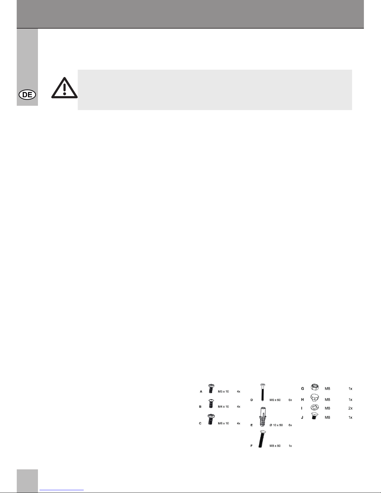
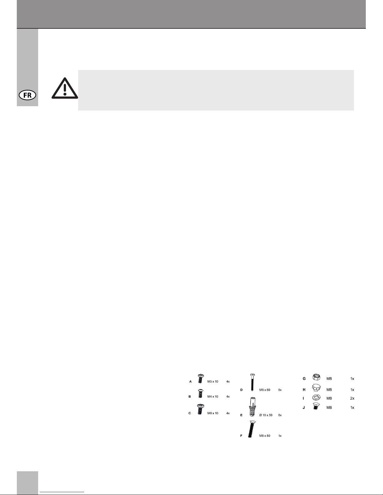
3 Lieferumfang:
1x Wandhalter
1x Befestigungsmaterial
(für Betonwände)
1x Bedienungsanleitung

3
TM
4 Sicherheitshinweise:
ACHTUNG! Die Wandprüfung sowie die Montage und Demontage des Produkts
darf nur durch ausgebildetes Fachpersonal erfolgen! Es besteht u. a. Stromschlag-, Quetsch- und Absturzgefahr!
• Ihr CABSTONETM Produkt ist kein Spielzeug und gehört nicht in Kinderhände, weil
zerbrechliche, kleine und verschluckbare Teile enthalten sind, die bei unsachgemäßem
Gebrauch Personen schädigen können!
• Bitte bringen Sie das System und die daran befestigten Geräte so an, dass keine
Personen oder Sachen z.B. durch Herabstürzen verletzt oder beschädigt werden
können.
• Lassen Sie Verpackungsmaterial nicht einfach liegen, da sich spielende Kinder
daran schneiden können. Weiterhin besteht die Gefahr des Verschluckens und Einat
mens von Kleinmaterial und Dämmmaterial.
• Wir empfehlen die Wandmontage nur von qualizierten Fachkräften ausführen zu
lassen.
• Um Unfälle zu vermeiden, ist es notwendig vor der Installation die Wandstruktur zu
überprüfen bzw. sorgfältig eine sichere Stelle zur Montage auszuwählen. Achten Sie
hierbei auf in der Wand liegende, stromführende Kabel oder andere Leitungen und
beschädigen Sie diese nicht!
• Die Wand muss an der Montagestelle stark genug sein um ein Gewicht von mindestens
dem Vierfachen des Gesamtgewichtes des Produktes, der Audio-/Videogeräte, der
Halter und des Montagematerials zu tragen.
• Lesen Sie hierzu auch das Kapitel „technische Daten“.
• Der Montageort muss in der Lage sein, Erdbeben oder sonstigen starken Erschütterun
gen standzuhalten.
• Vermeiden Sie Stellen mit hohen Temperaturen oder Feuchtigkeit, bzw. Stellen, die mit
Wasser in Berührung kommen können.
• Legen Sie bei der Montage den Bildschirm NIEMALS auf die Frontseite, lehnen Sie den
Bildschirm gegen eine Wand oder eine stabile Fläche. Das Hinlegen auf die Frontseite
des Bildschirms könnte einen permanenten Schaden verursachen!
• Installieren Sie das Produkt nicht in der Nähe von Klimaanlagenöffnungen oder an einer
Stelle, an der es übermäßig viel Staub oder Rauch gibt.
• Montieren Sie es nur an einer vertikalen Wand. Vermeiden Sie schräge Oberächen,
weil dann andere Zugbelastungen auf das Material einwirken können.
• Installieren Sie das Produkt nicht an Stellen, an denen es Erschütterungen oder
Schwingungen ausgesetzt ist.
• Modizieren und ändern Sie weder das Produkt noch Zubehörteile! Beachten Sie dazu
auch das Kapitel „Gewährleistung und Haftung“. Verwenden Sie keine beschädigten
Teile.
• Ziehen Sie alle Schrauben fest. Wenden Sie aber nicht zu viel Kraft an, um das Brechen
der Schrauben und Überdrehen der Gewinde zu vermeiden.
• Die Bohrungen bleiben an der Wand sichtbar, wenn der Wandhalter und dessen
Zubehör entfernt werden. Nach längerem Gebrauch kann ein Fleck an der Wand
zurückbleiben.
• Installieren Sie das Produkt nicht an Stellen mit direkter Sonneneinstrahlung, bzw.
starkem Licht. Dies fördert beim Anschauen der Bildschirmanzeige das Ermüden der
Augen. Halten Sie um die Ausgabe-, sowie Audio-/Videogeräte und um das gesamte
System ausreichend Freiraum um eine gute Belüftung und Freigängigkeit zu gewähr
leisten und Beschädigungen zu vermeiden.
4
Bedienungsanleitung
• Achten Sie beim Transport auf die im Kapitel „technischen Daten“ gelisteten Angaben
und treffen Sie geeignete Transportmaßnahmen.
• Bei Fragen, Defekten, mechanischen Beschädigungen, Störungen und anderen nicht
durch diese Anleitung behebbaren Funktionsproblemen, wenden Sie sich an Ihren
Händler zur Reparatur oder zum Austausch wie in Kapitel „Gewährleistung und
Haftung“ beschrieben.
• Beachten Sie den maximalen Traglasten im Kapitel „technischen Daten“.
• Bitte beachten Sie auch die Nutzungsbedingungen im Kapitel „bestimmungsgemäßer
Gebrauch“.
• Die mitgelieferten Komponenten sind ausschließlich für eine Montage an einer
massiven Stein- und Betonwand geeignet. Sollte die Beschaffenheit Ihrer Wand
abweichen, müssen Sie entsprechendes Montagematerial benutzen. Ziehen Sie in
jedem Fall eine Fachkraft zu Rate.
• Achten Sie bei der Montage des Bildschirms an den Wandhalter unbedingt auf die
passende Gewindestärke.
5 Montage:
ACHTUNG! Die Montage und Demontage darf nur durch geschultes Fachpersonal
erfolgen. Weiterführende Informationen nden Sie im Kapitel
„Sicherheitshinweise“ und „Problembehebung“.
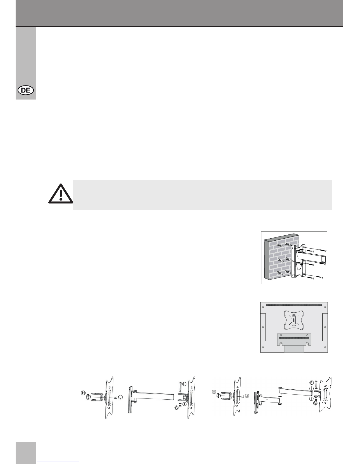
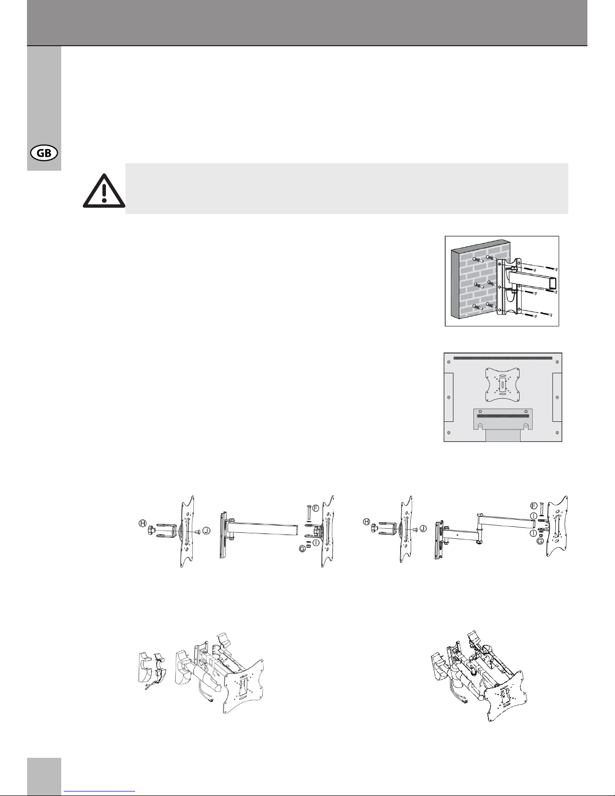
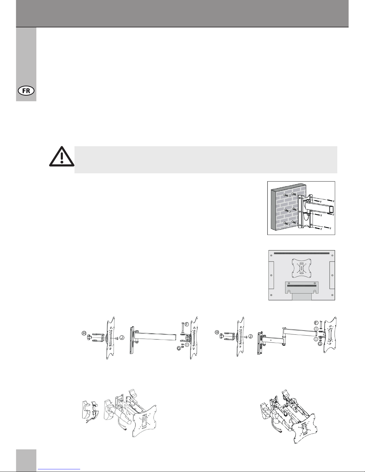
Wandmontage:
Bitte benutzen Sie den Wandhalter als Schablone um die
Bohrlöcher in der Wand mit einer Wasserwaage zu markieren.
Prüfen Sie vor dem Bohren, ob sich Gas-, Wasser, oder
Stromleitungen hinter der Wand benden. Bohren Sie die
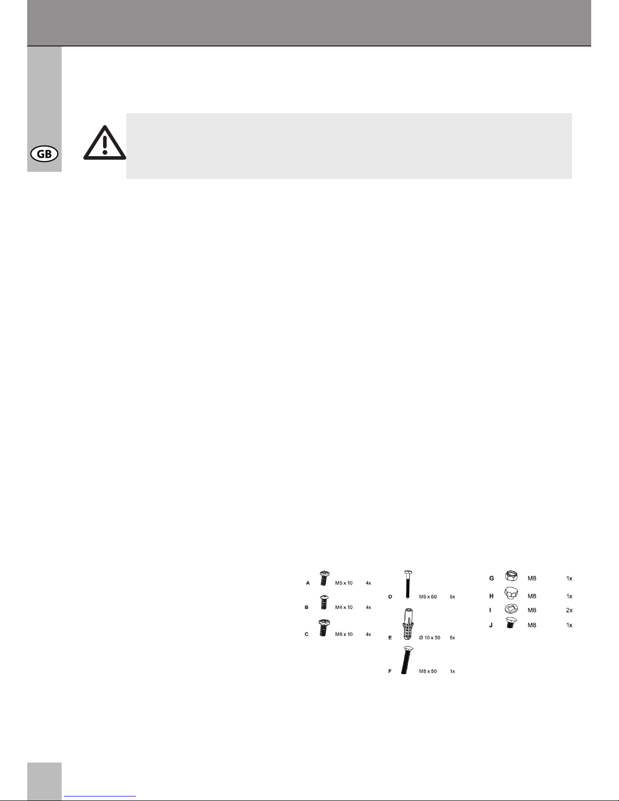
Löcher mit einem 10mm Steinbohrer 60mm tief. Stecken Sie
jeweils einen Wanddübel (E) in die Bohrlöcher. Bringen Sie nun
den Wandhalter mit den 6 Wandschrauben (D) an.
Bildschirmmontage:
Montieren Sie die Bildschirmhalterung an der Aufnahme
mittels Schrauben (J) und der Stellschraube (H). Bringen Sie
die Bildschirmhalterung mit den mitgelieferten Schrauben (A),
(B) oder (C) an Ihren Bildschirm an
CAB WH EASYSCOPE M (25-74 cm) CAB WH EASYSCOPE Multi (25-74 cm)
Schritt 1
Schritt 2
5
TM
Schritt 3
6 Gewährleistung und Haftung:
• Der Hersteller gewährt auf ein neues Produkt 2 Jahre Garantie.
• Da der Hersteller keinen Einuss auf den Wandtyp und die Installation des
Wandmont agesets hat, deckt die Garantie des Produkts nur das Montageset selbst ab.
• Falls ein Fehler oder Defekt an Ihrem Gerät festgestellt werden sollte, wenden Sie sich
bitte an Ihren Fachhändler und zeigen Sie ggf. Ihre Quittung oder Rechnung als
Kaufnachweis vor. Ihr Händler wird den Fehler entweder vor Ort beheben, oder das
Gerät an den Hersteller weiterleiten. Sie erleichtern unseren Technikern Ihre Arbeit sehr,
wenn Sie eventuelle Fehler ausführlich beschreiben – nur dann haben Sie Gewähr, dass
auch selten auftretende Fehler mit Sicherheit gefunden und beseitigt werden!
• Sollte Ihr Händler nicht erreichbar sein, können Sie uns auch direkt kontaktieren.
• Der Hersteller haftet nicht für Personen- oder Sachschäden, die durch unsachgemäße
Installation oder Bedienung, die nicht in dieser Anleitung beschrieben sind, entstanden
sind. Dazu zählt u. a. jegliche Änderung und Modikation des Produktes und seines
Zubehörs.
• Ein anderer als in dieser Betriebsanleitung beschriebener Einsatz ist unzulässig und
führt zu Gewährleistungsverlust, Garantieverlust und Haftungsausschluss.
• Druckfehler und Änderungen an Gerät, Verpackung oder Anleitung behalten wir uns vor.
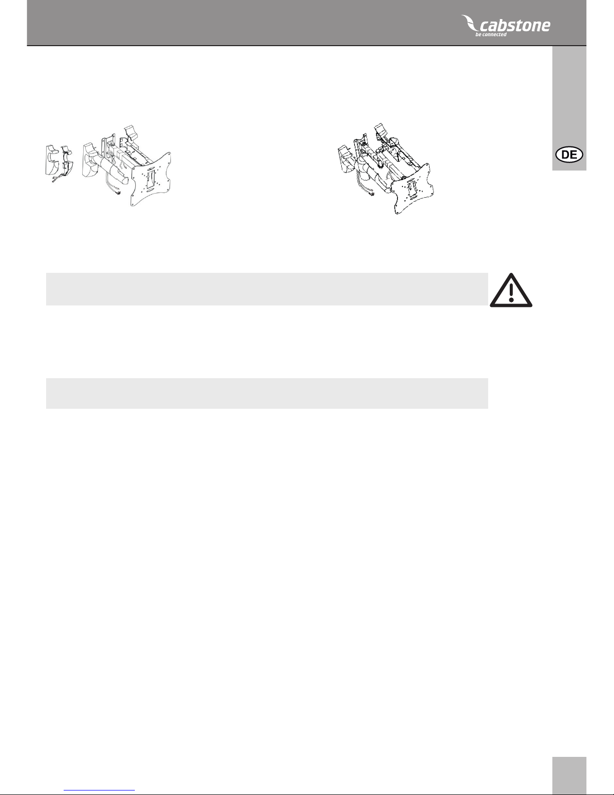
HINWEIS:
Kabelverlegung:
CAB WH EASYSCOPE M (25-74 cm) CAB WH EASYSCOPE Multi (25-74 cm)
Verlegen Sie die Kabel wie nebenstehend abgebildet (Abb. 4).
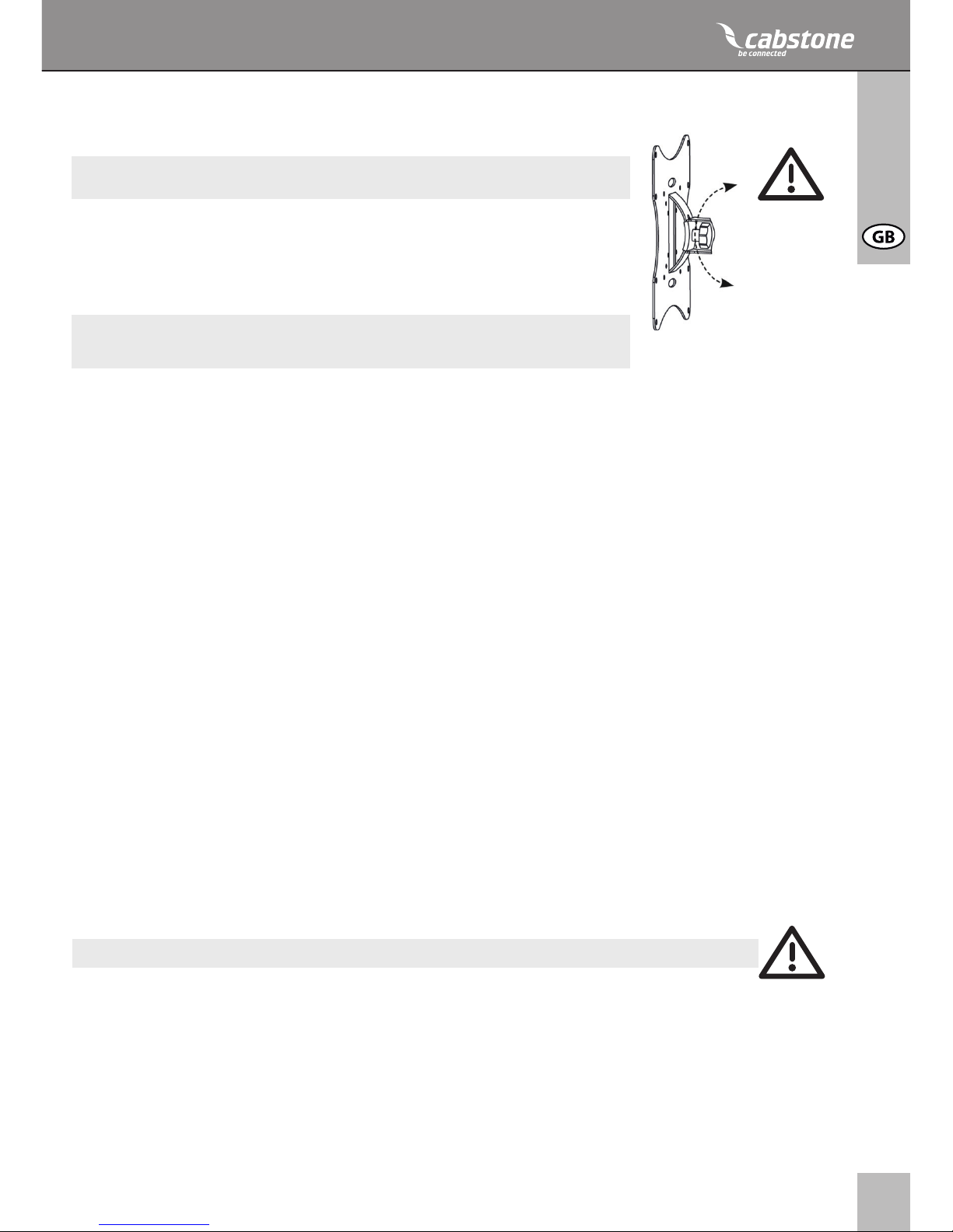
Justierung:
ACHTUNG! Halten Sie den Bildschirm während der gesamten Justierung immer
fest!
• Drehen Sie die Stellschraube ein- oder zweimal gegen den Abbildung 5
Uhrzeigersinn. (Abbildung 5)
• Stellen Sie die gewünschte Bildschirmneigung ein.
• Drehen Sie die Stellschraube im Uhrzeigersinn wieder fest.
Die Montage ist beendet. Zur Demontage gehen Sie in rückwärtiger Reihenfolge
vor.
Schritt 4
6
Bedienungsanleitung
8 Problembehebung:
Problem
Wie kann die Wandqualität getestet werden?
Welche Löcher müssen
gebohrt werden?
Der Wandhalter lässt
sich nur schwer
ausrichten.
andere Fragen:
Maßnahme
Prüfen Sie die Wandstärke und das Material unter
Putz und Tapeten. Ziehen
Sie ausgebildetes
Fachpersonal zu Rate.
Bitte lesen Sie hierzu
Kapitel das Lieferumfang
und Montage.
Lassen Sie sich von einer
zweiten Person helfen
und beachten Sie die
„Sicherheitshinweise“!
Prüfen Sie alle Befestigungen und konsultieren
Sie ggf. Ihren Händler.
Kontaktieren Sie uns.
Kennzeichnung
Verkehrslasten für Wohn-
räume nden Sie z.B. in
Normen wie DIN 1055
und EN 594.
Die Löcher sind durch
Skizzen gekennzeichnet.
Kontaktdaten stehen auf
der Rückseite.
7 Pege, Wartung, Lagerung und Transport:
• Reinigen Sie Ihr Produkt mit einem trockenen oder bei starker Verschmutzung mit einem
leicht angefeuchteten Leinentuch. Achten Sie hierbei unbedingt auf die stromführenden
Leitungen Ihres Gerätes! Ziehen Sie vorher den Netzstecker!
• Achten Sie beim Schwenken der Geräteteile darauf, dass Sie keine Körperteile in den
Schwenkvorrichtungen einklemmen!
ACHTUNG! Es besteht Stromschlag- und Quetschgefahr!
• Halten Sie um das Anzeigegerät ausreichend Freiraum, um eine ausreichende Belüftung
zu gewährleisten und prüfen Sie bei Bedarf die Freigängigkeit des Systems.
• Kontrollieren Sie regelmäßig alle Befestigungen und Schrauben auf festen Sitz und
ziehen Sie diese bei Lockerung wieder fest. Dies kann z.B. bei häugem Bewegen
eintreten.
• Vermeiden Sie Stellen mit hohen Temperaturen, Feuchtigkeit, bzw. Stellen, die nass
werden können, auch bei Pege, Wartung, Lagerung und Transport.
• Die Bohrungen bleiben an der Wand sichtbar, wenn das Gerät und das Wandmontages
et entfernt werden. Nach längerem Gebrauch kann ein Fleck an der Wand zurückblei
ben.
• Achten Sie beim Transport auf die Sicherheitszeichen auf der Verpackung.
7
TM
Modell 51928 / 51929 51930 / 51931
Bildschirmdiagonale 250 – 740 mm, 10“ – 30“ 250 – 740 mm, 10“ – 30“
max. Traglast 30 kg 30 kg
Gewicht 2,0 kg 2,3 kg
Maße 220 x 220 x 330 mm 220 x 220 x 470 mm
VESA Lochmaße 50 x 50 mm 50 x 50 mm
75 x 75 mm 75 x 75 mm
100 x 100 mm 100 x 100 mm
100 x 200 mm 100 x 200 mm
200 x 200 mm 200 x 200 mm
Wandabstand 100 - 330 mm 100 - 470 mm
Neigungswinkel +/-20° +/-20°
Schwenkwinkel +/-90° +/-90°
9 Technische Daten:
10 Informationen zum VESA-Standard:
Um die Befestigungsmöglichkeiten von Monitoren, TV-Geräten und deren Ständer und
Wandhalter benutzerfreundlich zu vereinheitlichen, hat die VESA (Video Electronic
Standard Organisation) für die oben genannten Anwendungen 3 Standards festgelegt. Mit
Hilfe des auf Ihrem Anzeigegerät oder in dessen Betriebsanleitung stehenden jeweiligen
VESA-Standards und den technischen Daten in dieser Anleitung können Sie die möglichen
Befestigungspunkte denieren. Einige Modelle lassen eine stufenlose, individuelle
Befestigung zu.(z.B. 300 x 300mm für Sony TVs).
VESA Klasse Befestigungslochabstand von Monitoren
MIS-D: 75 x 75 oder 100 x 100mm
MIS-E: 200 x 100 oder 200 x 200mm
MIS-F: 400 x 200, 400 x 400, 600 x 200,
600 x 400 oder 800 x 400mm
11 Entsorgungshinweise:
Dieses Produkt gehört nicht in den Hausmüll. Bitte geben Sie Ihr Gerät am Ende seiner
Lebensdauer an die dafür eingerichteten, öffentlichen Sammelstellen oder an die Verkaufs-
stelle kostenlos zurück. Einzelheiten zur Entsorgung regelt das jeweilige Landesrecht.
Wertstoffe werden dem Recyclingkreislauf zugeführt, um daraus neue Rohstoffe zu
gewinnen. Folgende Wertstoffe werden in kommunalen Sammelstellen gesammelt:
• Altglas, Kunststoffe, Altmetalle, Bleche uvm.
Mit dieser Art der Verwertung von Altgeräten leisten Sie einen wichtigen Beitrag zum
Schutz unserer Umwelt.
8
Contents:
1 Description and Function 8
2 Intended Use 8
3 Parts Package 8
4 Notes on Safety 9
5 Installation 10
6 Warranty and Liability 11
7 Care, Maintenance, Storage, and Transport 11
8 Troubleshooting 12
9 Specications 12
10 Information for VESA Standard 13
11 Note on Waste Disposal 13
Manual
CAB WH EASYSCOPE M 25-74 cm (10 - 30“) Silver / Black
CAB WH EASYSCOPE Multi 25-74 cm (10 - 30“) Silver / Black
ATTENTION! Please read the user‘s guide completely and carefully. It is part of
the product and includes important information for proper installation and use.
Keep this guide to have it available, when there are uncertainties, or the product
will be passed on.
Description and Function:
Your CABSTONETM EASYSCOPE wall bracket is made of rm, powder-coated steal, and
is designed to be an attachment of your LED/LCD/plasma display to solid walls. Your
EASYSCOPE model can be tilted and swiveled variably.
2 Intended Use:
This product is used to attach LED/LCD/plasma displays with specic screen sizes,
weight, and points of attachment to a wall, please see “Specications” for details. Any
use other than that specied in Chapter 1 is not allowed. Failure to observe or comply
with regulations and notes on safety may cause serious accidents, bodily injuries, as well
as damages to property. Please read the Chapter “Warranty and Liability”.
3 Parts Package:
1x Wall Bracket
1x Mounting Material (for concrete walls)
1x User Manual
9
TM
4 Notes on Safety:
ATTENTION! Only trained professionals are authorized to inspect the wall, as
well as install and remove the product! Among others, there is a risk of electric
shock, bruises, and crashes!
• Your CABSTONETM product is not a toy and is not meant for children, because it
contains small parts which can be swallowed and can injure when used inappropriately!
• NEVER place the display screen on its front side during installation, lean the display
screen against a wall or a sturdy surface. Placing the display screen on its front side
could cause permanent damage!
• Please install the system and devices attached to it in a way that persons cannot be
injured, or objects not be damaged for example by dropping.
• Please remove the packing materials, because children may cut themselves on them
while playing. Furthermore, there is a risk of swallowing and inhalation of incidentals and
insulating material.
• We recommend that the wall installation only be performed by qualied technicians.
• To avoid accidents it is necessary to check the wall structure before installation, or to
carefully look for a safe place for installation. Look out for live cables embedded in the
wall!
• The wall must be strong enough at the place of installation to carry at least the fourfold
of the total weight of the product, the audio / video devices, the bracket, and the
installation material.
• Please also read the Chapter “Specications”.
• The place of installation must be able to withstand earthquakes, or other strong
vibrations.
• Avoid places with high temperatures, or humidity, or places which might come into
contact with water.
• Do not install the product close to openings of air conditioners, or at places with an
excessive amount of dust or smoke.
• Install it only on a vertical wall. Avoid slant surfaces, because other kind of tensile stress
may then interact with the material.
• Do not install the product at places subject to vibration, or oscillation.
• Do not modify and alter any accessories! Make sure you also read the Chapter “Warran
ty and Liability”. Do not use any damaged parts.
• Tighten all screws. Do not use too much force to avoid breakage of screws and overtur
ning of threads.
• Drill holes are still visible on the wall after the device bracket and the cable management
system is removed. After use for a longer time period, a spot may remain on the wall.
• Do not install the product at places subject to direct solar radiation, or strong light. This
will increasingly tire the eyes while looking at the display. Keep sufcient space around
the output devices, as well as audio / video devices, and around the entire system to
ensure proper ventilation and clearance, and to avoid damages.
• During transport, observe the details listed in the Chapter “Specications”, and imple
ment measures suitable for transport.
• For questions, defects, mechanical damages, malfunctions, and other functional
problems which cannot be resolved by this guide, please contact your dealer for repair or
replacement, as described in the Chapter “Warranty and Liability”.
• Please observe the maximum bearing loads listed in the Chapter “Specications”.
• Please also observe the terms of use described in the Chapter “Intended Use”.
• The supplied components are only suitable for installation to a solid stone and concrete
10
Manual
wall. If the structure of your wall is different, corresponding installation material must be
used. In any case, consult a specialist.
• Make sure to observe the correct thread size during installation of the display screen to
the wall bracket.
5 Installation:
ATTENTION! Only trained professionals are authorized to inspect the wall, as well
as install and remove the product! For more information please read the Chapters
“Notes on Safety” and “Troubleshooting”.
Wall Installation: 1
Please use the wall bracket as a template to mark the holes to
be drilled in the wall using a level. Check, if gas or water pipes,
or power lines are behind the wall before drilling. Use a 10 mm
stone drill to bore the holes to a depth of 60 mm. Insert one
dowel (E) into each of the drilled holes. Now, use the 6 wall
screws (D) to attach the wall bracket.
Installation of Display Screen: 2
Use screws (J), and the adjusting screw (H) to attach the
screen bracket to the receptacle. Use the supplied screws (A),
(B), or (C) to fasten the screen bracket to your display screen.
CAB WH EASYSCOPE M (25-74 cm) CAB WH EASYSCOPE Multi (25-74 cm)
Layout of Cables:
CAB WH EASYSCOPE M (25-74 cm) CAB WH EASYSCOPE Multi (25-74 cm)
Lay out the cables as illustrated in the adjacent picture (Fig. 4).
Step 1
Step 2
Step 3
11
TM
6 Warranty and Liability:
• The manufacturer warrants this new device for 2 years.
• As the manufacturer has no inuence on the wall type and the installation of the wall
installation kit, warranty of the product only applies to the installation kit.
• If any fault or damage is detected on your device, please contact your dealer and provide
your sales slip or invoice as evidence of the purchase, if necessary. Your dealer will
repair the fault either on site, or send the device to the manufacturer. You make the work
of our technicians considerably easier, when you describe possible faults in detail – only
then you can be assured that faults occurring only rarely will be found and repaired with
certainty!
• If your dealer cannot be contacted, you can also contact us directly.
• The manufacturer is not liable for damages to persons or property caused by improper
installation or operation not described in this guide. This includes, among others, any
alteration and modication of the product and its accessories.
• Any use other than described in this user‘s guide is not permitted, and causes loss of
warranty, loss of guarantee, and non-liability.
• We reserve our right for misprints and changes of the device, packing, or user‘s guide.
7 Care, Maintenance, Storage, and Transport:
• Use a dry linen cloth to clean your product, or use a slightly moist cloth for heavy stains.
Look out for live cables of your device during cleaning! Pull the plug prior to cleaning!
• Make sure no body parts will be pinched in the swivel device, when parts of the device
are swiveled!
ATTENTION! There is a risk of electric shock and bruises!
• Make sure there is sufcient space around the display unit to ensure proper ventilation,
and check the clearance of the system, if necessary.
• Periodically check, if all attachments and screws are secured, and tighten them again
when they are loose. This may be caused for example by frequent movements.
• Avoid places with high temperatures, humidity, or places which can become wet, also
during care, maintenance, storage, and transport.
• Drill holes are still visible on the wall after the device and the wall installation kit is
removed. After use for a longer time period, a spot may remain on the wall.
• Follow the safety symbols on the packing during transport.
NOTE:
Adjustment: 5
ATTENTION! Always hold the display screen during the entire
adjustment!
• Drive the adjusting screw one or two turns a counter-clockwise direction
(Figure 5).
• Adjust the display screen to the desired inclination.
• Tighten the adjusting screw again in a clockwise direction.
The installation is completed. Please proceed in reverse order for
disassembly.
Step 4
12
Manual
8 Troubleshooting:
Problem
How can the wall quality
be tested?
Which holes must be
drilled?
The wall bracket is hard
to align.
other questions:
Correction
Check the wall thickness,
and the material below
plaster and wallpaper.
Consult trained professio-
nals.
Please read the Chapters
„Parts Package“ and
„Installation“.
Ask a second person for
help, and observe the
„Notes on Safety“!
Please read Chapter 5.
Check all attachments,
and contact your dealer, if
necessary.
Contact us.
Marking
Live loads for living
space are listed for
example in standards
such as DIN 1055, and
EN 594.
Holes are marked in
drawings.
Contact details – back
of cover sheet
Model 51928 / 51929 51930 / 51931
screen size 250 – 740 mm, 10“ – 30“ 250 – 740 mm, 10“ – 30“
max. load 30 kg 30 kg
Weight 2.0 kg 2.3 kg
Dimensions 220 x 220 x 330 mm 220 x 220 x 470 mm
VESA hole distance 50 x 50 mm 50 x 50 mm
75 x 75 mm 75 x 75 mm
100 x 100 mm 100 x 100 mm
100 x 200 mm 100 x 200 mm
200 x 200 mm 200 x 200 mm
Wall distance 100 - 330 mm 100 - 470 mm
Angle of inclination +/-20° +/-20°
Swivel angle +/-90° +/-90°
9 Specications:
13
TM
10 Information for VESA-Standard:
To harmonize attachment options of monitors, TV devices, and their stands and wall
brackets in a user-friendly manner, VESA (Video Electronic Standard Organization) dened
3 standards for the applications mentioned above. Using the relevant VESA standard
specied on your display unit, or in its user‘s guide, and the specications in Chapter
“Specications” in this guide you are able to dene the possible points of attachment.
Some models allow for an innitely variable individual attachment.
(eg. 300 x 300 mm for Sony TVs)
VESA Class Hole distance for attachment of monitors
MIS-D: 75 x 75, or 100 x 100 mm
MIS-E: 200 x 100, or 200 x 200 mm
MIS-F: 400 x 200, 400 x 400, 600 x 200, 600 x 400,
or 800 x 400 mm
11 Note on Waste Disposal:
This product should be not disposed together with domestic waste. Please return your
device free of charge at the end of its service life at public collection points established for
this purpose, or at the sales outlet. Details for disposal are regulated in the relevant federal
state law. Potential recyclable materials are fed into the recycling cycle to obtain new raw
materials from them. Following recyclable materials are collected a local collection points:
• Waste glass, plastic, waste metal, metal sheet, and more.
This type of recycling of waste equipment contributes signicantly to the protection of our
environment.
14
Table des matières:
1 Description et fonctions 14
2 Utilisation prévue 14
3 Éléments contenus dans le paquet 14
4 Notes relatives à la sécurité 15
5 Installation 16
6 Garantie et responsabilité 17
7 Entretien, maintenance, stockage et transport 17
8 Dépannage 18
9 Spécications 19
10 Informations pour la norme VESA 19
11 Note relative à l‘élimination des déchets 19
ATTENTION ! Veuillez lire le présent guide de l‘utilisateur en entier et avec
attention. Il fait partie intégrante du produit et comprend d‘importantes
informations pour une bonne installation et une bonne utilisation. Conservez ce
guide à portée de main, pour pouvoir vous y reporter en cas d‘incertitude, ou pour
le donner au nouvel utilisateur si vous donnez le produit à quelqu‘un d‘autre.
1 Description et fonctions:
Votre support mural CABSTONETM EASYSCOPE est composé d‘acier résistant revêtu de
poudre, et est conçu pour l‘élément reliant votre écran LED / LCD / plasma à un mur
plein. Votre modèle EASYSCOPE peut être incliné et pivoté de façon variable.
2 Utilisation prévue:
Ce produit est utilisé pour la xation d‘écrans LED / LCD / plasma de tailles, poids et
points de xation différents, sur un mur ; pour les détails, veuillez consulter les „Spécications“. Toute utilisation autre que celles spéciées dans le Chapitre 1 est interdite. Le
non-respect des instructions et consignes de sécurité risque de provoquer des accidents
graves, des accidents corporels, ainsi que des dommages matériels. Veuillez lire le
chapitre „Garantie et responsabilité“.
3 Éléments contenus dans le paquet:
1x support mural
1x Material de montage (pour les
les murs en béton)
1x Notice de l‘utilisation
CAB WH EASYSCOPE M 25-74 cm (10 - 30“) Argenté / Noire
CAB WH EASYSCOPE Multi 25-74 cm (10 - 30“) Argenté / Noire
Notice d’utilisation

15
TM
4 Consignes de sécurité:
ATTENTION ! Seuls les professionnels formés sont autorisés à inspecter le mur,
ainsi qu‘à installer et démonter le produit ! Les autres personnes s‘exposent à
des risques d‘électrocution, de blessures et de casse !
• Votre produit CABSTONETM n‘est pas un jouet et n‘a pas été conçu pour des enfants,
car il contient des pièces de petite taille qui risquent d‘être avalées et risquent de blesser
si elles ne sont pas utilisées de façon appropriée !
• Veuillez installer le système et les appareils xés au support de telle façon que personne
ne risque d‘être blessé ou qu‘aucun objet ne risque d‘être endommagé en cas de chute.
• Veuillez enlever les matériaux d‘emballage, car les enfants risqueraient de se couper en
jouant avec. En outre, il y a un risque d‘ingestion ou d‘inhalation de matériaux dange
reux.
• Nous recommandons que l‘installation au mur soit faite uniquement par un technicien
qualié.
• Pour éviter les accidents, il est nécessaire de contrôler la structure du mur avant
l‘installation ; choisissez soigneusement un endroit qui permet de garantir la sécurité.
Faites attention aux câbles électriques qui peuvent se trouver dans le mur !
• Le mur doit être sufsamment résistant, sur le lieu d‘installation, pour supporter au
moins quatre fois le poids total du produit, des équipements audio et vidéo, du support et
des matériaux d‘isolation.
• Veuillez aussi vous reporter au Chapitre « Caractéristiques ».
• Le lieu d‘installation doit être capable de supporter les tremblements de terre et autres
secousses fortes.
• Évitez d‘installer le produit dans des lieux aux températures élevées ou très humides, ou
dans un lieu où le produit risquerait d‘entrer en contact avec de l‘eau.
• NE JAMAIS placer l‘écran sur sa face avant lors de l‘installation, faites reposer l‘écran
d‘afchage contre un mur ou une surface solide. Le fait de placer l‘écran sur sa face
avant peut provoquer des dégâts permanents !
• Ne pas installer le produit à proximité de l‘ouverture d‘appareils de conditionnement
d‘air, ou dans des endroits avec des quantités excessives de poussière ou de fumée.
• Installez exclusivement sur un mur vertical. Évitez les surfaces inclinées, car d‘autres
tensions risquent d‘être imposées qui peuvent interagir avec les matériaux.
• Ne pas installer le produit dans des endroits soumis à vibrations ou oscillations.
• Ne modier et n‘altérer aucun des accessoires ! Veuillez bien à lire aussi le Chapitre «
Garantie et responsabilité ». Ne pas utiliser de pièces endommagées.
• Serrez toutes les vis. Ne pas forcer trop de façon à éviter de casser les vis ou
d‘endommager le letage.
• Les orices percés restent visibles sur le mur une fois que le support pour appareil et le
système de gestion des câbles ont été enlevés. Après une période de temps prolongée,
une marque peut apparaître sur le mur.
• Ne pas installer le produit dans des endroits exposés directement au soleil ou à un
éclairage puissant. Cela augmenterait la fatigue oculaire imposée lorsque l‘on regarde à
l‘écran. Conservez sufsamment d‘espace libre autour des appareils de sortie, ainsi
qu‘autour des appareils audio et vidéo, et autour du système pour permettre une bonne
ventilation, et éviter les dommages.
• Pendant le transport, suivez les consignes données dans le Chapitre « Caractéristiques
», et prenez les mesures adéquates pour le transport.
• Pour les questions, défauts, dommages mécaniques, dysfonctionnements et autres
problèmes fonctionnels que vous ne parviendriez pas à résoudre avec le présent guide,
16
Notice d’utilisation
veuillez vous adresser à votre détaillant pour une réparation ou un remplacement, ainsi
que décrit dans le Chapitre « Garantie et responsabilité ».
• Veuillez respecter les charges maximales spéciées dans le Chapitre
«Caractéristiques».
• Veuillez respecter également les instructions données dans le Chapitre « Utilisation
prévue ». Les éléments fournis ne conviennent que pour l‘installation sur un mur plein en
pierre ou en béton. Si la structure de votre mur est différente, il faut utiliser le matériel
d‘installation correspondant. Dans tous les cas, consulter un spécialiste.
• Assurez-vous de respecter la bonne taille de letage lors de l‘installation de l‘écran sur le
support mural.
5 Installation:
Installation murale: 1
Veuillez utiliser le support mural comme gabarit pour marquer la
position des xations murales à l‘aide d‘un niveau. Vériez
l‘absence de conduites d‘eau, de tuyaux de gaz et de lignes
électriques derrière le mur avant de percer. Utilisez un foret pour
la pierre de 10 mm an de percer les trous d‘une profondeur de
60 mm. Insérez une cheville (E) dans chacun des trous forés.
Utilisez à présent les 6 vis (D) pour xer le support mural.
Installation de l‘écran: 2
Utilisez les vis (J), et la vis de réglage (H) pour relier le support
de l‘écran au réceptacle. Utilisez les vis fournies (A), (B), ou (C)
pour attacher le support d‘écran à votre écran.
CAB WH EASYSCOPE M (25-74 cm) CAB WH EASYSCOPE Multi (25-74 cm)
3
Disposition des câbles:
CAB WH EASYSCOPE M (25-74 cm) CAB WH EASYSCOPE Multi (25-74 cm)
4
Disposez les câbles comme illustré sur l‘image ci-contre (Fig.4).
Étape 1
Étape 2
Étape 3
ATTENTION ! Seuls les professionnels formés sont autorisés à installer l‘appareil
au mural, ou à démonter l‘appareil. Pour de plus amples informations, veuillez lire
les Chapitres « Notes relatives à la sécurité » et « Dépannage ».
 Loading...