

Page 1
Title Page
HSIM-W85
User’s Guide
L
9032842-01
L
S
L
S
L
S
L
S
L
S
L
S
S
HSIM-W85
L
S
CPU
Page 2

Page 3

Only qualified personnel should perform installation
procedures.
NOTICE
Cabletron Systems reserves the right to make changes in specifications and other information
contained in this document without prior notice. The reader should in all cases consult Cabletron
Systems to determine whether any such changes have been made.
The hardware, firmware, or software described in this manual is subject to change without notice.
IN NO EVENT SHALL CABLETRON SYSTEMS BE LIABLE FOR ANY INCIDENTAL,
INDIRECT, SPECIAL, OR CONSEQUENTIAL DAMAGES WHATSOEVER (INCLUDING BUT
NOT LIMITED TO LOST PROFITS) ARISING OUT OF OR RELATED TO THIS MANUAL OR
THE INFORMATION CONTAINED IN IT, EVEN IF CABLETRON SYSTEMS HAS BEEN
ADVISED OF, KNOWN, OR SHOULD HAVE KNOWN, THE POSSIBILITY OF SUCH
DAMAGES.
CAUTION
LISTED EQUIPMENT BY A QUALIFIED SERVICE PERSON. CHECK THE EQUIPMENT
OPERATION/INSTALLATION INSTR UCTIONS AND/OR EQUIPMENT MANUFACTURER TO
VERIFY/CONFIRM YOUR EQUIPMENT IS SUITABLE FOR INSTALLED APPLICATION
CARDS.
CAUTION
JACK) FROM THE TELEPHONE SYSTEM WHEN INSTALLING OR WHEN THE COVERS
ARE REMOVED FROM THE HOST PRODUCT.
CAUTION
INSIDE OF THE EQUIPMENT ENCLOSURE ADJA CENT T O THE T1 CARD.
: THE HSIM-W85 IS INTENDED TO BE INSTALLED IN CSA CERTIFIED/UL
: ALWAYS DISCONNECT T1 BOARD (THE ONE WITH THE TELEPHONE PLUG/
: APPLY THE ENCLOSED ADHESIVE WARNING LABEL TO THE OUTSIDE OR
1999 by Cabletron Systems, Inc., P.O. Box 5005, Rochester, NH 03866-5005
All Rights Reserved
Printed in the United States of America
Part Number: 9032842-01 March 1999
Cabletron Systems
All other product names mentioned in this manual may be trademarks or registered trademarks of
their respective companies.
and
LANVIEW
are registered trademarks of Cabletron Systems, Inc.
HSIM-W85 User’s Guide i
Page 4

Notice
FCC NOTICE
This device complies with Part 15 of the FCC rules. Operation is subject to the following two
conditions: (1) this device may not cause harmful interference, and (2) this device must accept any
interference received, including interference that may cause undesired operation.
NOTE:
This equipment has been tested and found to comply with the limits for a Class A digital
device, pursuant to Part 15 of the FCC rules. These limits are designed to provide reasonable
protection against harmful interference when the equipment is operated in a commercial environment.
This equipment uses, generates, and can radiate radio frequency energy and if not installed in
accordance with the operator’s manual, may cause harmful interference to radio communications.
Operation of this equipment in a residential area is likely to cause interference in which case the user
will be required to correct the interference at his own expense.
WARNING:
party responsible for compliance could void the user’s authority to operate the equipment.
Changes or modifications made to this device which are not expressly approved by the
INDUSTRY CANADA NOTICE
The Industry Canada label identifies certified equipment. This certification means that the equipment
meets certain telecommunications network protective, operational and safety requirements. The
department does not guarantee the equipment will operate to the user’s satisfaction.
Before installing this equipment, users should ensure that it is permissible to be connected to the
facilities of the local telecommunications company. The equipment must also be installed using an
acceptable method of connection. In some cases, the company’s inside wiring associated with a single
line individual service may be extended by means of a certified connector assembly (telephone
extension cord). The customer should be aware that compliance with the above conditions may not
prevent degradation of service in some situations.
Repairs to certified equipment should be made by an authorized Canadian maintenance facility
designated by the supplier. Any repairs or alterations made by the user to this equipment, or
equipment malfunctions, may give the telecommunications company cause to request the user to
disconnect the equipment.
Users should ensure for their own protection that the electrical ground connections of the power
facility, telephone lines and internal metallic water pipe system, if present, are connected together.
This precaution may be particularly important in rural areas.
CAUTION:
THEMSELVES, BUT SHOULD CONTACT THE APPROPRIATE ELECTRIC INSPECTION
AUTHORITY, OR ELECTRICIAN, AS APPROPRIATE.
This digital apparatus does not exceed the Class A limits for radio noise emissions from digital
apparatus set out in the Radio Interference Regulations of the Industry Canada.
Le présent appareil numérique n’émet pas de bruits radioélectriques dépassant les limites applicables
aux appareils numériques de la class A prescrites dans le Règlement sur le brouillage radioélectrique
édicté par le ministère des Communications du Canada.
USERS SHOULD NOT ATTEMPT TO MAKE SUCH CONNECTIONS
ii HSIM-W85 User’s Guide
Page 5

Notice
VCCI NOTICE
This is a Class A product based on the standard of the Voluntary Control Council for Interference by
Information Technology Equipment (VCCI). If this equipment is used in a domestic environment,
radio disturbance may arise. When such trouble occurs, the user may be required to take corrective
actions.
CABLETRON SYSTEMS, INC.
PROGRAM LICENSE AGREEMENT
IMPORTANT: THIS LICENSE APPLIES FOR USE OF PRODUCT IN THE UNITED
STATES OF AMERICA AND BY UNITED STATES OF AMERICA
GOVERNMENT END USERS.
BEFORE OPENING OR UTILIZING THE ENCLOSED PRODUCT,
CAREFULLY READ THIS LICENSE AGREEMENT.
This document is an agreement (“Agreement”) between You, the end user, and Cabletron Systems,
Inc. (“Cabletron”) that sets forth your rights and obligations with respect to the Cabletron software
program (“Program”) in the package. The Program may be contained in firmware, chips or other
media. UTILIZING THE ENCLOSED PRODUCT, YOU ARE AGREEING TO BECOME BOUND
BY THE TERMS OF THIS AGREEMENT, WHICH INCLUDES THE LICENSE AND THE
LIMITATION OF WARRANTY AND DISCLAIMER OF LIABILITY. IF YOU DO NOT AGREE
TO THE TERMS OF THIS AGREEMENT, RETURN THE UNOPENED PRODUCT TO
CABLETRON OR YOUR DEALER, IF ANY, WITHIN TEN (10) DA YS FOLLO WING THE DA TE
OF RECEIPT FOR A FULL REFUND.
IF YOU HAVE ANY QUESTIONS ABOUT THIS AGREEMENT, CONTACT CABLETRON
SYSTEMS (603) 332-9400. Attn: Legal Department.
1. LICENSE.
package subject to the terms and conditions of this License Agreement.
You may not copy, reproduce or transmit any part of the Program except as permitted by the
Copyright Act of the United States or as authorized in writing by Cabletron.
2. OTHER RESTRICTIONS.
Program.
3. APPLICABLE LAW.
laws and in the state and federal courts of New Hampshire. You accept the personal jurisdiction and
venue of the New Hampshire courts.
You have the right to use only the one (1) copy of the Program provided in this
You may not reverse engineer, decompile, or disassemble the
This License Agreement shall be interpreted and governed under the
HSIM-W85 User’s Guide iii
Page 6

Notice
4. EXPORT REQUIREMENTS.
regulation by agencies of the U.S. Government, including the U.S. Department of Commerce, which
prohibit export or diversion of certain technical products to certain countries, unless a license to export
the product is obtained from the U.S. Government or an exception from obtaining such license may be
relied upon by the exporting party.
If the Program is exported from the United States pursuant to the License Exception CIV under
the U.S. Export Administration Regulations, You agree that You are a civil end user of the Program
and agree that You will use the Program for civil end uses only and not for military purposes.
If the Program is exported from the United States pursuant to the License Exception TSR under
the U.S. Export Administration Regulations, in addition to the restriction on transfer set forth in
Sections 1 or 2 of this Agreement, You agree not to (i) reexport or release the Program, the source
code for the Program or technology to a national of a country in Country Groups D:1 or E:2 (Albania,
Armenia, Azerbaijan, Belarus, Bulgaria, Cambodia, Cuba, Estonia, Georgia, Iraq, Kazakhstan,
Kyrgyzstan, Laos, Latvia, Libya, Lithuania, Moldova, North Korea, the People’s Republic of China,
Romania, Russia, Rwanda, Tajikistan, Turkmenistan, Ukraine, Uzbekistan, Vietnam, or such other
countries as may be designated by the United States Government), (ii) export to Country Groups D:1
or E:2 (as defined herein) the direct product of the Program or the technology, if such foreign
produced direct product is subject to national security controls as identified on the U.S. Commerce
Control List, or (iii) if the direct product of the technology is a complete plant o r any major
component of a plant, export to Country Groups D:1 or E:2 the direct product of the plant or a major
component thereof, if such foreign produced direct product is subject to national security controls as
identified on the U.S. Commerce Control List or is subject to State Department controls under the
U.S. Munitions List.
5. UNITED STATES GOVERNMENT RESTRICTED RIGHTS.
was developed solely at private expense; (ii) contains “restricted computer software” submitted with
restricted rights in accordance with section 52.227-19 (a) through (d) of the Commercial Computer
Software-Restricted Rights Clause and its successors, and (iii) in all respects is proprietary data
belonging to Cabletron and/or its suppliers. For Department of Defense units, the Product is considered
commercial computer software in accordance with DFARS section 227.7202-3 and its successors, and
use, duplication, or disclosure by the Government is subject to restrictions set forth herein.
6. EXCLUSION OF WARRANTY.
writing, Cabletron makes no warranty, expressed or implied, concerning the Program (including its
documentation and media).
CABLETRON DISCLAIMS ALL WARRANTIES, OTHER THAN THOSE SUPPLIED TO
YOU BY CABLETRON IN WRITING, EITHER EXPRESS OR IMPLIED, INCLUDING BUT
NOT LIMITED TO IMPLIED WARRANTIES OF MERCHANTABILITY AND FITNESS FOR A
PARTICULAR PURPOSE, WITH RESPECT TO THE PROGRAM, THE ACCOMPANYING
WRITTEN MATERIALS, AND ANY A CCOMP ANYING HARDWARE.
7. NO LIABILITY FOR CONSEQUENTIAL DAMAGES.
CABLETRON OR ITS SUPPLIERS BE LIABLE FOR ANY DAMAGES WHATSOEVER
(INCLUDING, WITHOUT LIMITATION, DAMAGES FOR LOSS OF BUSINESS, PROFITS,
BUSINESS INTERRUPTION, LOSS OF BUSINESS INFORMATION, SPECIAL, INCIDENTAL,
CONSEQUENTIAL, OR RELIANCE DAMAGES, OR OTHER LOSS) ARISING OUT OF THE
USE OR INABILITY TO USE THIS CABLETRON PRODUCT, EVEN IF CABLETRON HAS
BEEN ADVISED OF THE POSSIBILITY OF SUCH DAMAGES. BECAUSE SOME STATES DO
NOT ALLOW THE EXCLUSION OR LIMITATION OF LIABILITY FOR CONSEQUENTIAL OR
INCIDENTAL DAMAGES, OR IN THE DURATION OR LIMITATION OF IMPLIED
WARRANTIES IN SOME INSTANCES, THE ABOVE LIMITATION AND EXCLUSIONS MAY
NOT APPLY TO YOU.
You understand that Cabletron and its Affiliates are subject to
The enclosed Product (i)
Except as may be specifically provided by Cabletron in
IN NO EVENT SHALL
iv HSIM-W85 User’s Guide
Page 7

Notice
CABLETRON SYSTEMS SALES AND SERVICE, INC.
PROGRAM LICENSE AGREEMENT
IMPORTANT: THIS LICENSE APPLIES FOR USE OF PRODUCT IN THE UNITED
STATES OF AMERICA AND BY UNITED STATES OF AMERICA
GOVERNMENT END USERS.
BEFORE OPENING OR UTILIZING THE ENCLOSED PRODUCT,
CAREFULLY READ THIS LICENSE AGREEMENT.
This document is an agreement (“Agreement”) between You, the end user, and Cabletron Systems
Sales and Service, Inc. (“Cabletron”) that sets forth your rights and obligations with respect to the
Cabletron software program (“Program”) in the package. The Program may be contained in firmware,
chips or other media. UTILIZING THE ENCLOSED PRODUCT, YOU ARE AGREEING TO
BECOME BOUND BY THE TERMS OF THIS AGREEMENT, WHICH INCLUDES THE
LICENSE AND THE LIMITATION OF WARRANTY AND DISCLAIMER OF LIABILITY. IF
YOU DO NOT AGREE TO THE TERMS OF THIS AGREEMENT, RETURN THE UNOPENED
PRODUCT TO CABLETRON OR YOUR DEALER, IF ANY, WITHIN TEN (10) DAYS
FOLLOWING THE DATE OF RECEIPT FOR A FULL REFUND.
IF YOU HAVE ANY QUESTIONS ABOUT THIS AGREEMENT, CONTACT CABLETRON
SYSTEMS (603) 332-9400. Attn: Legal Department.
1. LICENSE.
package subject to the terms and conditions of this License Agreement.
You may not copy, reproduce or transmit any part of the Program except as permitted by the
Copyright Act of the United States or as authorized in writing by Cabletron.
2. OTHER RESTRICTIONS.
Program.
3. APPLICABLE LAW.
laws and in the state and federal courts of New Hampshire. You accept the personal jurisdiction and
venue of the New Hampshire courts.
4. EXPORT REQUIREMENTS.
regulation by agencies of the U.S. Government, including the U.S. Department of Commerce, which
prohibit export or diversion of certain technical products to certain countries, unless a license to export
the product is obtained from the U.S. Government or an exception from obtaining such license may be
relied upon by the exporting party.
If the Program is exported from the United States pursuant to the License Exception CIV under
the U.S. Export Administration Regulations, You agree that You are a civil end user of the Program
and agree that You will use the Program for civil end uses only and not for military purposes.
If the Program is exported from the United States pursuant to the License Exception TSR under
the U.S. Export Administration Regulations, in addition to the restriction on transfer set forth in
Sections 1 or 2 of this Agreement, You agree not to (i) reexport or release the Program, the source
code for the Program or technology to a national of a country in Country Groups D:1 or E:2 (Albania,
Armenia, Azerbaijan, Belarus, Bulgaria, Cambodia, Cuba, Estonia, Georgia, Iraq, Kazakhstan,
Kyrgyzstan, Laos, Latvia, Libya, Lithuania, Moldova, North Korea, the People’s Republic of China,
Romania, Russia, Rwanda, Tajikistan, Turkmenistan, Ukraine, Uzbekistan, Vietnam, or such other
countries as may be designated by the United States Government), (ii) export to Country Groups D:1
or E:2 (as defined herein) the direct product of the Program or the technology, if such foreign
produced direct product is subject to national security controls as identified on the U.S. Commerce
Control List, or (iii) if the direct product of the technology is a complete plant o r any major
You have the right to use only the one (1) copy of the Program provided in this
You may not reverse engineer, decompile, or disassemble the
This License Agreement shall be interpreted and governed under the
You understand that Cabletron and its Affiliates are subject to
HSIM-W85 User’s Guide v
Page 8

Notice
component of a plant, export to Country Groups D:1 or E:2 the direct product of the plant or a major
component thereof, if such foreign produced direct product is subject to national security controls as
identified on the U.S. Commerce Control List or is subject to State Department controls under the
U.S. Munitions List.
5. UNITED STATES GOVERNMENT RESTRICTED RIGHTS.
was developed solely at private expense; (ii) contains “restricted computer software” submitted with
restricted rights in accordance with section 52.227-19 (a) through (d) of the Commercial Computer
Software-Restricted Rights Clause and its successors, and (iii) in all respects is proprietary data
belonging to Cabletron and/or its suppliers. For Department of Defense units, the Product is considered
commercial computer software in accordance with DFARS section 227.7202-3 and its successors, and
use, duplication, or disclosure by the Government is subject to restrictions set forth herein.
6. EXCLUSION OF WARRANTY.
writing, Cabletron makes no warranty, expressed or implied, concerning the Program (including its
documentation and media).
CABLETRON DISCLAIMS ALL WARRANTIES, OTHER THAN THOSE SUPPLIED TO
YOU BY CABLETRON IN WRITING, EITHER EXPRESS OR IMPLIED, INCLUDING BUT
NOT LIMITED TO IMPLIED WARRANTIES OF MERCHANTABILITY AND FITNESS FOR A
PARTICULAR PURPOSE, WITH RESPECT TO THE PROGRAM, THE ACCOMPANYING
WRITTEN MATERIALS, AND ANY A CCOMP ANYING HARDWARE.
7. NO LIABILITY FOR CONSEQUENTIAL DAMAGES.
CABLETRON OR ITS SUPPLIERS BE LIABLE FOR ANY DAMAGES WHATSOEVER
(INCLUDING, WITHOUT LIMITATION, DAMAGES FOR LOSS OF BUSINESS, PROFITS,
BUSINESS INTERRUPTION, LOSS OF BUSINESS INFORMATION, SPECIAL, INCIDENTAL,
CONSEQUENTIAL, OR RELIANCE DAMAGES, OR OTHER LOSS) ARISING OUT OF THE
USE OR INABILITY TO USE THIS CABLETRON PRODUCT, EVEN IF CABLETRON HAS
BEEN ADVISED OF THE POSSIBILITY OF SUCH DAMAGES. BECAUSE SOME STATES DO
NOT ALLOW THE EXCLUSION OR LIMITATION OF LIABILITY FOR CONSEQUENTIAL OR
INCIDENTAL DAMAGES, OR IN THE DURATION OR LIMITATION OF IMPLIED
WARRANTIES IN SOME INSTANCES, THE ABOVE LIMITATION AND EXCLUSIONS MAY
NOT APPLY TO YOU.
Except as may be specifically provided by Cabletron in
The enclosed Product (i)
IN NO EVENT SHALL
CABLETRON SYSTEMS LIMITED
PROGRAM LICENSE AGREEMENT
IMPORTANT: THIS LICENSE APPLIES FOR USE OF PRODUCT IN THE UNITED
STATES OF AMERICA AND BY UNITED STATES OF AMERICA
GOVERNMENT END USERS.
BEFORE OPENING OR UTILIZING THE ENCLOSED PRODUCT,
CAREFULLY READ THIS LICENSE AGREEMENT.
This document is an agreement (“Agreement”) between You, the end user, and Cabletron Systems
Limited (“Cabletron”) that sets forth your rights and obligations with respect to the Cabletron
software program (“Program”) in the package. The Program may be contained in firmware, chips or
other media. UTILIZING THE ENCLOSED PRODUCT, YOU ARE AGREEING TO BECOME
BOUND BY THE TERMS OF THIS AGREEMENT, WHICH INCLUDES THE LICENSE AND
THE LIMITATION OF WARRANTY AND DISCLAIMER OF LIABILITY. IF YOU DO NOT
AGREE TO THE TERMS OF THIS AGREEMENT, RETURN THE UNOPENED PRODUCT TO
CABLETRON OR YOUR DEALER, IF ANY, WITHIN TEN (10) DA YS FOLLO WING THE DA TE
OF RECEIPT FOR A FULL REFUND.
vi HSIM-W85 User’s Guide
Page 9

Notice
IF YOU HAVE ANY QUESTIONS ABOUT THIS AGREEMENT, CONTACT CABLETRON
SYSTEMS (603) 332-9400. Attn: Legal Department.
1. LICENSE.
package subject to the terms and conditions of this License Agreement.
You may not copy, reproduce or transmit any part of the Program except as permitted by the
Copyright Act of the United States or as authorized in writing by Cabletron.
2. OTHER RESTRICTIONS.
Program.
3. APPLICABLE LAW.
law. The English courts shall have exclusive jurisdiction in the event of any disputes.
4. EXPORT REQUIREMENTS.
regulation by agencies of the U.S. Government, including the U.S. Department of Commerce, which
prohibit export or diversion of certain technical products to certain countries, unless a license to export
the product is obtained from the U.S. Government or an exception from obtaining such license may be
relied upon by the exporting party.
If the Program is exported from the United States pursuant to the License Exception CIV under
the U.S. Export Administration Regulations, You agree that You are a civil end user of the Program
and agree that You will use the Program for civil end uses only and not for military purposes.
If the Program is exported from the United States pursuant to the License Exception TSR under
the U.S. Export Administration Regulations, in addition to the restriction on transfer set forth in
Sections 1 or 2 of this Agreement, You agree not to (i) reexport or release the Program, the source
code for the Program or technology to a national of a country in Country Groups D:1 or E:2 (Albania,
Armenia, Azerbaijan, Belarus, Bulgaria, Cambodia, Cuba, Estonia, Georgia, Iraq, Kazakhstan,
Kyrgyzstan, Laos, Latvia, Libya, Lithuania, Moldova, North Korea, the People’s Republic of China,
Romania, Russia, Rwanda, Tajikistan, Turkmenistan, Ukraine, Uzbekistan, Vietnam, or such other
countries as may be designated by the United States Government), (ii) export to Country Groups D:1
or E:2 (as defined herein) the direct product of the Program or the technology, if such foreign
produced direct product is subject to national security controls as identified on the U.S. Commerce
Control List, or (iii) if the direct product of the technology is a complete plant o r any major
component of a plant, export to Country Groups D:1 or E:2 the direct product of the plant or a major
component thereof, if such foreign produced direct product is subject to national security controls as
identified on the U.S. Commerce Control List or is subject to State Department controls under the
U.S. Munitions List.
5. UNITED STATES GOVERNMENT RESTRICTED RIGHTS.
was developed solely at private expense; (ii) contains “restricted computer software” submitted with
restricted rights in accordance with section 52.227-19 (a) through (d) of the Commercial Computer
Software-Restricted Rights Clause and its successors, and (iii) in all respects is proprietary data
belonging to Cabletron and/or its suppliers. For Department of Defense units, the Product is considered
commercial computer software in accordance with DFARS section 227.7202-3 and its successors, and
use, duplication, or disclosure by the Government is subject to restrictions set forth herein.
You have the right to use only the one (1) copy of the Program provided in this
You may not reverse engineer, decompile, or disassemble the
This License Agreement shall be governed in accordance with English
You understand that Cabletron and its Affiliates are subject to
The enclosed Product (i)
HSIM-W85 User’s Guide vii
Page 10

Notice
6. EXCLUSION OF WARRANTY.
writing, Cabletron makes no warranty, expressed or implied, concerning the Program (including its
documentation and media).
CABLETRON DISCLAIMS ALL WARRANTIES, OTHER THAN THOSE SUPPLIED TO
YOU BY CABLETRON IN WRITING, EITHER EXPRESS OR IMPLIED, INCLUDING BUT
NOT LIMITED TO IMPLIED WARRANTIES OF MERCHANTABILITY AND FITNESS FOR A
PARTICULAR PURPOSE, WITH RESPECT TO THE PROGRAM, THE ACCOMPANYING
WRITTEN MATERIALS, AND ANY A CCOMP ANYING HARDWARE.
7.
NO LIABILITY FOR CONSEQUENTIAL DAMAGES. IN NO EVENT SHALL
CABLETRON OR ITS SUPPLIERS BE LIABLE FOR ANY DAMAGES WHATSOEVER
(INCLUDING, WITHOUT LIMITATION, DAMAGES FOR LOSS OF BUSINESS, PROFITS,
BUSINESS INTERRUPTION, LOSS OF BUSINESS INFORMATION, SPECIAL, INCIDENTAL,
CONSEQUENTIAL, OR RELIANCE DAMAGES, OR OTHER LOSS) ARISING OUT OF THE
USE OR INABILITY TO USE THIS CABLETRON PRODUCT, EVEN IF CABLETRON HAS
BEEN ADVISED OF THE POSSIBILITY OF SUCH DAMAGES. BECAUSE SOME STATES DO
NOT ALLOW THE EXCLUSION OR LIMITATION OF LIABILITY FOR CONSEQUENTIAL OR
INCIDENTAL DAMAGES, OR IN THE DURATION OR LIMITATION OF IMPLIED
WARRANTIES IN SOME INSTANCES, THE ABOVE LIMITATION AND EXCLUSIONS MAY
NOT APPLY TO YOU.
Except as may be specifically provided by Cabletron in
viii HSIM-W85 User’s Guide
Page 11

CONTENTS
CHAPTER 1 INTRODUCTION
1.1 Firmware Revision.......................................................................1-1
1.2 Using This Manual.......................................................................1-2
1.3 Overview......................................................................................1-3
1.4 Data Flow in the HSIM-W85........................................................ 1-4
1.5 Features ......................................................................................1-4
1.5.1 Connectivity .................................................................... 1-5
1.5.2 HDLC..............................................................................1-5
1.5.3 Inverse Multiplexing (IMUX)............................................ 1-6
1.5.4 Priority Queuing..............................................................1-6
1.5.5 DS1 Alarm ......................................................................1-7
1.5.6 SNMP and MIB Support .................................................1-7
1.5.7 LANVIEW Diagnostic LEDs............................................1-7
1.6 Document Conventions...............................................................1-8
1.7 Related Documentation............................................................... 1-9
1.8 Getting Help...............................................................................1-10
CHAPTER 2 INSTALLATION
2.1 Unpacking the HSIM-W85........................................................... 2-1
2.2 Installing the HSIM-W85..............................................................2-2
2.2.1 Installing the HSIM-W85 in an Interface Module ............2-2
2.2.2 Installing the HSIM-W85 in a Standalone Device...........2-5
2.3 Connecting the HSIM-W85 to the Network..................................2-6
CHAPTER 3 LANVIEW LEDs
3.1 LANVIEW LEDs...........................................................................3-1
CHAPTER 4 MANAGEMENT
4.1 Local Management...................................................................... 4-1
4.2 Network Tools..............................................................................4-3
4.2.1 Commands .....................................................................4-4
4.2.2 Built-in Commands .........................................................4-7
4.2.3 Special Commands....................................................... 4-14
4.3 Sample IMUX Configuration...................................................... 4-15
HSIM-W85 User’s Guide ix
Page 12

Contents
CHAPTER 5 TROUBLESHOOTING
5.1 Troubleshooting the HSIM-W85..................................................5–1
5.1.1 Hardware Troubleshooting.............................................5–1
5.1.2 Investigating Software Configuration Problems .............5–3
5.1.3 Problems with the Firmware Image................................5–3
APPENDIX A SPECIFICATIONS
A.1 Physical Properties ..................................................................... A-1
A.2 Environmental Requirements...................................................... A-2
A.3 Regulatory Compliance............................................................... A-2
APPENDIX B TYPICAL CONFIGURATION
APPENDIX C FCC PART 68 - USER’S INFORMATION
x HSIM-W85 User’s Guide
Page 13
CHAPTER 1
INTRODUCTION
Welcome to the Cabletron Systems
HSIM-W85 User’s Guide
. This
manual describes the HSIM-W85 and provides information concerning
features, installation, the use of management, troubleshooting, and
specifications.
A general working knowledge of Wide Area Networking (WAN),
including T1 Networking, Ethernet and data communications networks,
and their physical layer components is helpful when installing this device.
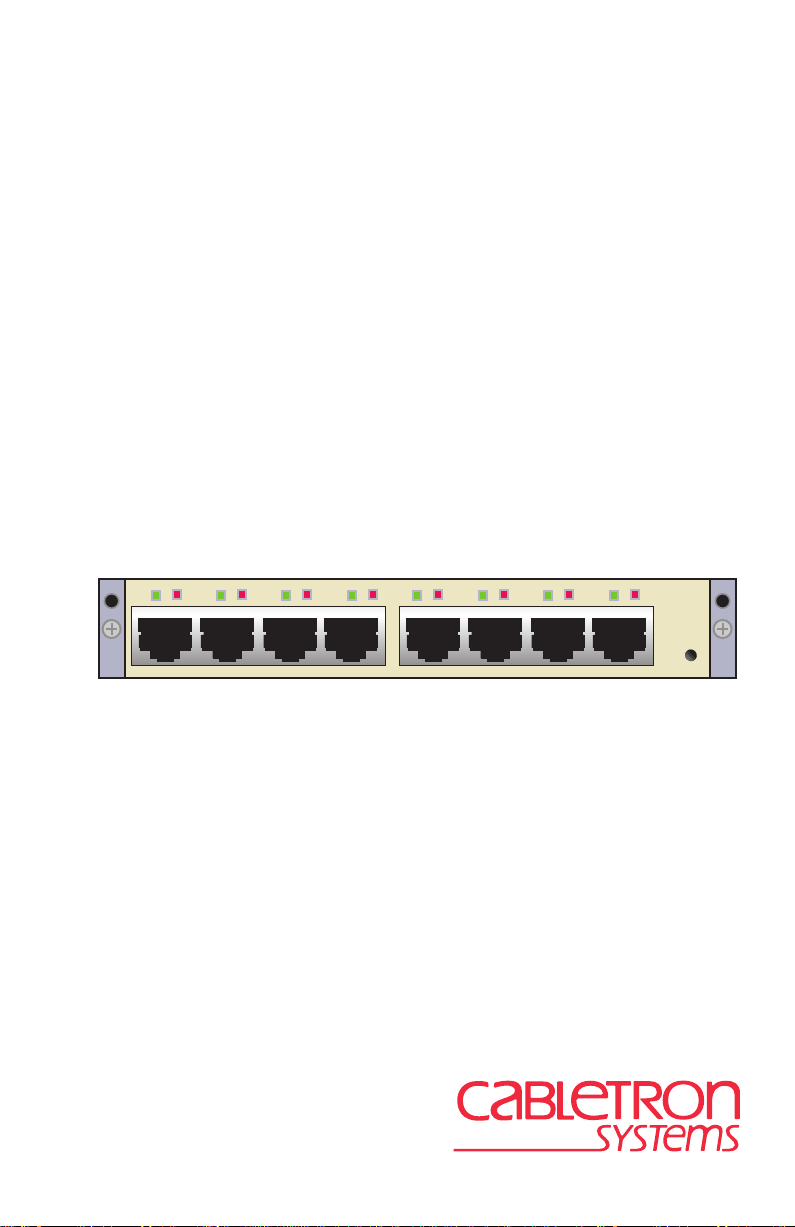
The HSIM-W85 has 8 RJ45 T1 ports. Figure 1-1 shows the HSIM-W85.
L
L
S
L
S
L
S
L
S
L
S
L
S
S
Figure 1-1 HSIM-W85
HSIM-W85
L
S
CPU
1.1 FIRMWARE REVISION
Important Notice
Depending on the firmware version used in the HSIM-W85, some
features described in this document may not be supported. Refer to the
Release Notes shipped with the HSIM-W85 to determine which features
are supported.
This manual covers Firmware Revision level 04.08.XX. Later revisions
may be reflected in an updated manual. Please verify the revision le vel of
your device, to ensure that this manual meets your needs.
HSIM-W85 User’s Guide 1-1
Page 14

Chapter 1:
Introduction
1.2 USING THIS MANUAL
Reading through this manual completely will help you understand the
features and capabilities of the HSIM-W85. The following list provides
an overview of each section of this manual:
Chapter 1,
Introduction
, outlines the contents of this manual, describes
the HSIM-W85 features and provides information on how to obtain
related manuals and technical support.
Chapter 2,
Installation
, describes how to install an HSIM-W85 into an
interface module or a standalone device (host platform).
NOTE
Chapter 3,
The term “host platform” is used to describe the interface
module, or standalone device, into which the HSIM-W85 can
be installed.
LANVIEW LEDs
, describes how to use the HSIM-W85
LEDs to monitor performance and status.
Chapter 4,
Management
, describes the Network Tools needed for
configuration of the HSIM-W85.
Chapter 5,
Troubleshooting
, describes some of the common
troubleshooting problems and possible solutions.
Appendix A,
Specifications
, lists the operating specifications and
regulatory compliance of the HSIM-W85.
Appendix B,
T ypical Configuration
, displays possible configurations for
the HSIM-W85.
Appendix C, FCC PART 68 - User’s Information, explains the FCC rules
for the HSIM-W85.
1-2 HSIM-W85 User’s Guide
Page 15

Overview
1.3 OVERVIEW
The HSIM-W85 extends the functionality of certain Cabletron Systems
platforms by providing an interface for Wide Area Network (WAN) DS1
services. The HSIM-W85 is a High Speed Interface Module (HSIM) used
to provide WAN services using the SmartSwitch series of products as a
platform. The HSIM-W85 has 8 physical DS1 interfaces, providing 8
separate logical DS1 connections. Eight separate T1 circuits can be
configured, or the circuits can be combined into various Inverse
Multiplexing (IMUX) groupings, up to a 12 Mbps full duplex data circuit
within a Layer 2 IMUX group.
The typical configuration is a head-end WAN aggregation point for up to
8 T1s into a single WAN physical interface. The HSIM-W85 is able to
uplink any combination of single T1s or multiple T1 IMUX groups to the
backbone. Refer to Appendix B for a diagram of a typical configuration.
The HSIM-W85 has its own i960 HD microprocessor used to process data
packets, provide simple configuration, Inverse Multiplexer functionality,
and statistics processing. The SmartSwitch host platform provides the
required logical IP Host services. The HSIM-W85 is designed to be
installed in any Cabletron Systems product that supports the High Speed
Interface Module.
The HSIM-W85 operates in two modes:
•
Switching
•
IMUX
The first mode, switching, is the default mode. The HSIM-W85 forwards
data packets received by the host platform out through the logical DS1
interfaces. It also forwards packets received in the DS1 interfaces to or
through the host. The default and only layer 2 WAN protocol used with
the HSIM-W85 is raw HDLC.
NOTE
HSIM-W85 User’s Guide 1-3
The host platform may operate in 802.1D bridging, 802.1Q
VLAN, or SecureFast mode.
Page 16

Chapter 1:
Introduction
The second mode of operation is using Cabletron Systems Inverse
Multiplexer (IMUX) functionality to aggregate multiple DS1 connections
into single higher bandwidth WAN connections. To operate in this mode,
the user configures the appropriate IMUX groups containing the DS1
connections.
Along with the built-in management features (Network Tools) described
in Chapter 4, the HSIM-W85 can be managed using SNMP. Statistical
data can be accessed via SNMP by referencing the interface group defined
in RFC 1213.
1.4 DATA FLOW IN THE HSIM-W85
The T1 data streams are terminated by T1 framers, which provide an
HDLC bit stream to the HDLC controller. The controller receives data
packets from each of the bit streams and places them in a memory
subsystem. The on board CPU examines the packet and notifies the host
of its arrival. Finally, a Cabletron proprietary ASIC transfers the data to
the host platform.
This process is followed in reverse when a packet is transmitted from the
host platform out the T1 ports. The host platform notifies the HSIM-W85
when a packet is coming and transfers the packet to the memory. The
HDLC format is applied to the data, then the data is framed to a T1
format, and passed to the framer. The T1 data is transmitted out through
the T1 interface.
1.5 FEATURES
The following are some of the highlights of the HSIM-W85 features:
•
Data Transfer Rates of 12 Mbps in full duplex, when running all eight
T1s carrying continuous data traffic of 64-byte packets or larger.
•
High-level Data Link Control (HDLC) protocol
•
T1 Inverse Multiplexing (IMUX)
•
WAN IP Priority Queuing functionality
•
DS1 Alarm Thresholds
•
SNMP support
1-4 HSIM-W85 User’s Guide
Page 17

Features
•
DS1 MIB Support
•
LANVIEW LEDs
1.5.1 Connectivity
The HSIM-W85 module supports WAN technology using eight live full
duplex T1 connections.
The primary function of the HSIM-W85 is to provide LAN-to-WAN
access. WAN physical connectivity will be supported through the use of a
T1 interface. LAN-to-WAN connectivity will be supported through
HDLC and T1 Inverse Multiplexing (IMUX).
The HSIM-W85 interoperates with those Cabletron Systems WAN
products that support raw HDLC as the WAN protocol. This support is
limited to the CyberSWITCH product line which supports HDLC:
•
CSX400 – Version 02.00.15 or higher
•
HSIM-W6 – Version 02.00.15 or higher
•
HSIM-W84 – Version 02.00.xx or higher
•
HSIM-W87 – SSR 2200 Version 04.05.06 or higher
1.5.2 HDLC
The High-level Data Link Control (HDLC) protocol is used in
conjunction with the Inverse Multiplexing (IMUX) feature to conserve a
user’s WAN bandwidth between two Cabletron Systems products, over a
point-to-point connection. Cabletron Systems products such as the
HSIM-W6, HSIM-W84, HSIM-W85, HSIM-W87, and CSX400 must be
in use on both ends of the WAN link for these functions to work. The
HDLC (RAW) protocol reduces the amount of overhead information that
needs to be contained within each data packet to direct it to its destination.
This decreased packet overhead provides the IMUX functions with more
bandwidth to transfer user data.
HSIM-W85 User’s Guide 1-5
Page 18

Chapter 1:
Introduction
1.5.3 Inverse Multiplexing (IMUX)
Cabletron Systems Inverse Multiplexing (IMUX) feature provides
enhanced throughput for users by following this process:
•
The IMUX function evenly distributes a data packet stream from the
LAN interface through multiple full T1 WAN interfaces on the
HSIM-W85.
•
Data packet streams received by the WAN interfaces on the other end
of the WAN links are then recombined, ordered, and transmitted to the
LAN interface.
The IMUX function is configured using the Network Tools command,
imux, described in Chapter 4.
NOTE
Cabletron Systems products that support Inverse Multiplexing
(IMUX), such as the HSIM-W6, CSX400, HSIM-W84,
HSIM-W85, and HSIM-W87, must exist on both ends of the
WAN link for the IMUX function to work. All bridging and
switching functions, such as 802.1D, SecureFast VLAN, and
802.1Q are able to run as normal on the host platform when
using the IMUX function on the HSIM-W85.
1.5.4 Priority Queuing
WAN IP Priority Queuing is used to prioritize IP packets from a specified
IP address. This prioritizing ensures that certain packets get through the
network, such as management packets which are necessary to the
operation of the network. It also ensures that routers that depend on
protocols with tight timing, such as RIP, do not time out. The prioritized
packets do not eliminate other traffic on the network, but are held in a
special queue, so that they are not discarded during oversubscribed traf fic
peaks. Priority Queuing can be enabled in management, using Network
Tools. Refer to the wanpq command in the
Management
chapter.
1-6 HSIM-W85 User’s Guide
Page 19

Features
1.5.5 DS1 Alarm
The DS1 Error Threshold Alarm Monitor allows the user to set error
thresholds. The monitor notifies the user of potential DS1 problems with
SNMP trap events.
The ds1alarm Monitor feature can be enabled in management, using
Network Tools. Refer to the ds1alarm command in the
chapter.
Management
1.5.6 SNMP and MIB Support
With SNMP support, the MIBs supported by the HSIM-W85 include:
•
RFC 1406 – Definitions of Managed Objects for the DS1 and E1
Interface Types
•
RFC 1213 (MIB II) support for the Interface Table
•
Cabletron Enterprise MIBs
•
RFC 2233 – Support for the Interface Stack Table
Refer to the Release Notes included with the host platform for a list of all
MIBs supported by the HSIM-W85. For information about how to extract
and compile individual MIBs, contact Cabletron Systems (Section 1.8).
1.5.7 LANVIEW Diagnostic LEDs
Cabletron Systems provides a visual diagnostic and monitoring system
called LANVIEW. The HSIM-W85 LANVIEW LEDs help you quickly
identify status of the device. Chapter 3 provides information on the
HSIM-W85 LEDs. The host platform LEDs may also indicate
information for the HSIM-W85. Refer to the appropriate host platform
manual for further information on the host platform LEDs.
HSIM-W85 User’s Guide 1-7
Page 20

Chapter 1:
Introduction
1.6 DOCUMENT CONVENTIONS
The following conventions are used throughout this document:
Note
NOTE
CAUTION
TIP
!
symbol. Calls the reader’s attention to any item of
information that may be of special importance.
Caution symbol. Contains information essential to avoid
damage to the equipment.
Electrical Hazard Warning symbol. Warns against an action
that could result in personal injury or death due to an electrical
hazard.
Tip symbol. Conveys helpful hints concerning procedures or
actions.
bold type Denotes either a user input or a highlighted screen selection.
RETURN Indicates either the ENTER or RETURN key, depending on your
keyboard.
ESC Indicates the keyboard Escape key.
SPACE bar Indicates the keyboard space bar key.
BACKSPACE Indicates the keyboard backspace key.
arrow keys Refers to the four keyboard arrow keys.
[-] Indicates the keyboard – key.
DEL Indicates the keyboard delete key.
italic type Italic type emphasizes important information, indicates variables,
and indicates complete document titles.
n.nn A period in numerals signals the decimal point indicator (e.g.,
1.75 equals one and three fourths), or the Decimal Dotted
Notation (DDN) for an IP address.
x Indicates the generic use of a letter (e.g., xxx indicates any
combination of three alphabetic characters).
1-8 HSIM-W85 User’s Guide
Page 21

Related Documentation
n Indicates the generic use of a number (e.g., 19nn indicates a
four-digit number in which the last two digits are unknown).
[] In the Local Management screens, the brackets indicate that a
value may be entered or selected. In the format descriptions in the
Network Tools section, required arguments are enclosed in [].
<> In the format descriptions in the Network Tools section, optional
arguments are enclosed in <>.
1.7 RELATED DOCUMENTATION
The documentation for the host platform in which the HSIM-W85 is to be
installed provides additional information about the setup of the
HSIM-W85. The host documentation is not listed below, as there can be
many different host platforms. This user’s guide may reference
procedures in these documents, where appropriate, but does not repeat
them.
Documents can be obtained on the World Wide Web in Adobe Acrobat
Portable Document Format (PDF) at the following site:
http://www.cabletron.com/
HSIM-W85 User’s Guide 1-9
Page 22

Chapter 1: Introduction
1.8 GETTING HELP
For additional support related to this device or document, contact
Cabletron Systems using the following methods:
World Wide Web http://www.cabletron.com/
Phone (603) 332-9400
Internet mail support@cabletron.com
FTP ftp://ftp.cabletron.com/
Login
Password
To send comments or suggestions concerning this document, contact the
Cabletron Systems Technical Writing Department via the following
email address: TechWriting@cabletron.com
Make sure to include the document Part Number in the email message.
Before calling Cabletron Systems, have the following information
ready:
• Your Cabletron Systems service contract number
• A description of the failure
anonymous
your email address
• A description of any action(s) already taken to resolve the problem
(e.g., changing mode switches, rebooting the unit, etc.)
• The serial and revision numbers of all involved Cabletron Systems
products in the network
• A description of your network environment (layout, cable type, etc.)
• Network load and frame size at the time of trouble (if known)
• The device history (i.e., have you returned the device before, is this a
recurring problem, etc.)
• Any previous Return Material Authorization (RMA) numbers
1-10 HSIM-W85 User’s Guide
Page 23

CHAPTER 2
INSTALLATION
To install the HSIM-W85 the following items are required:
• Antistatic wrist strap (shipped with the HSIM-W85)
• Phillips screwdriver
NOTE
Before attempting to use the HSIM-W85 you should be familiar
with the
IEEE 802.3 Specifications,
and T1 Networking.
2.1 UNPACKING THE HSIM-W85
The HSIM-W85 and the host platform are sensitive to static
discharges. Use an antistatic strap and observe all static
!
CAUTION
Unpack the HSIM-W85 as follows:
1. Remove the HSIM-W85 from the shipping box.
2. Leave the module in its antistatic bag until you are ready to install it.
3. Attach the antistatic wrist strap (refer to the instructions on the
4. After removing the module from its antistatic bag, visually inspect the
precautions during this procedure. Failure to do so could result
in damage to the HSIM-W85 or host platform.
antistatic wrist strap package for proper use).
device. If you notice any signs of damage, contact Cabletron Systems
immediately. Refer to Section 1.8 for instructions. Save the antistatic
bag in the event the module must be reshipped or relocated.
HSIM-W85 User’s Guide 2-1
Page 24

Chapter 2: Installation
2.2 INSTALLING THE HSIM-W85
Only qualified personnel should install or service this unit.
An HSIM-W85 can be installed in any Cabletron Systems device that
supports HSIM technology (e.g., 2H252-25R, 2E42-27, 6E132-25).
NOTE
Refer to the release notes for the version of firmware running
on the Cabletron Systems host platform to ensure that the
HSIM-W85 is supported.
The following subsections provide instructions for installing an
HSIM-W85 in a host platform. Refer to the specific interface module or
standalone device manual for exact HSIM slot and connector locations.
2.2.1 Installing the HSIM-W85 in an Interface Module
To install an HSIM-W85 in an interface module that supports HSIM
technology, perform the following steps.
1. Note the ports of the interface module that have cables attached to
them. Write down the ports and label the cables to make it easier to
reattach the network properly after the installation. Then disconnect
those cables from the ports.
2. Attach the antistatic wrist strap (refer to the instructions outlined on
the antistatic wrist strap package).
3. If the interface module is installed in a chassis, unlock the top and
bottom plastic locking tabs of the module faceplate.
4. Remove the module from the chassis, and place it down flat with the
internal components facing up.
5. Remove and save the two faceplate mounting screws securing the
HSIM coverplate and remove the coverplate. See Figure 2-1.
2-2 HSIM-W85 User’s Guide
Page 25

HSIM Coverplate
Faceplate Mounting Screws
Figure 2-1 Removing the HSIM Coverplate
Installing the HSIM-W85
Host Platform
2555_03
6. Refer to Figure 2-2 and place the HSIM-W85 behind the module
faceplate.
HSIM-W85 User’s Guide 2-3
Page 26

Chapter 2: Installation
Standoff Screws
Connector
Cutaway view of connector
Connector
HSIM-W85
L
S
L
S
L
S
L
S
L
S
L
S
L
S
L
HSIM-W85
S
CPU
HSIM
Pins
Standoffs
Faceplate Mounting Screws
Interface Module
or Device
mounting
Figure 2-2 Installing the HSIM-W85
7. Align the connector on the HSIM-W85 with the pins on the module.
Ensure that the HSIM-W85 connector aligns with the module
CAUTION
both the HSIM-W85 and the module.
connector pins to prevent bending the pins. This can damage
!
8. Press down firmly on the connector area of the HSIM-W85 until the
connector slides all the way onto the pins. Ensure that the standoffs on
the interface module align with the standoff screw holes on the
HSIM-W85.
9. Secure the HSIM-W85 to the module faceplate using the mounting
screws saved in step 5.
2-4 HSIM-W85 User’s Guide
Page 27

Installing the HSIM-W85
10. Secure the HSIM-W85 to the module standoffs using the standoff
screws included in the HSIM-W85 shipping materials.
11. Reinstall the interface module in the chassis.
12. Reattach the network cabling to the interface module.
2.2.2 Installing the HSIM-W85 in a Standalone Device
To install an HSIM-W85 into a standalone device (e.g., 2H252-25R)
perform the following steps:
1. Power down the device and remove the power cord.
2. Note the ports that have cables attached to them. Write down the ports
and label the cables to make it easier to reattach the network properly
after the installation. Then disconnect those cables from the ports.
To install the HSIM-W85 in a standalone device, the device
must first be powered down. Ensure that you remove the po wer
cord and ONLY the screws required to remove the chassis
cover.
3. Attach the antistatic wrist strap (refer to the instructions outlined on
the antistatic wrist strap package).
4. Remove the standalone device chassis cover (refer to your specific
standalone device documentation for instructions on removing the
chassis cover).
5. Refer back to Figure 2-1 and remove the two faceplate mounting
screws and the HSIM coverplate. Save the screws.
6. Refer back to Figure 2-2 and place the HSIM-W85 behind the
standalone device faceplate.
7. Align the HSIM connector of the HSIM-W85 with the pins on the
standalone device.
Ensure that the HSIM-W85 connector aligns with the device
connector pins to prevent bending the pins. This can damage
!
CAUTION
HSIM-W85 User’s Guide 2-5
both the HSIM-W85 and the device.
Page 28

Chapter 2: Installation
8. Press down firmly on the HSIM-W85 until the connector slides all the
way onto the HSIM pins. Ensure that the standoffs on the standalone
device align with the standoff screw holes on the HSIM-W85.
9. Secure the HSIM-W85 to the module faceplate using the mounting
screws saved in step 5.
10. Secure the HSIM-W85 to the module standoffs using the standoff
screws included in the HSIM-W85 shipping materials.
Ensure that the chassis cover is in place before reconnecting
the power cord.
11. Replace the chassis cover on the standalone device, reconnect the
power cord, and reconnect the standalone device to the network.
2.3 CONNECTING THE HSIM-W85 TO THE NETWORK
The HSIM-W85 is connected to the carrier’s DS1 service using twisted
pair cable. The cable may run a maximum of 5000 feet or greater,
depending on the dB loss of the cable. Refer to Appendix A for more
details on cable length. The Cabletron Systems part number for the T1
cable is 9732094.
2E42-27 with HSIM-W85
LSLSLSLSLSLSLSL
Cable Part
Number:
9372094
HSIM-W85
S
CPU
Wall Jack
Telco Cloud
2842_1
Figure B-3 HSIM-W85 Cable Connection
For information on configurations for the HSIM-W85, refer to
Appendix B.
2-6 HSIM-W85 User’s Guide
Page 29

CHAPTER 3
LANVIEW LEDs
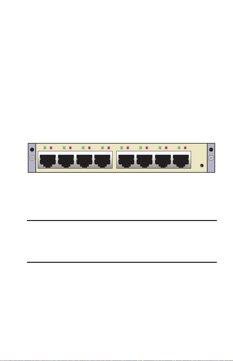
3.1 LANVIEW LEDS
This chapter describes how to use the LANVIEW LEDs to monitor the
HSIM-W85 status and diagnose HSIM-W85 problems. Figure 3-1 shows
the location of the HSIM-W85 LEDs.
Link
NOTE
Status
L
L
S
L
S
L
S
L
S
L
S
L
S
L
S
Figure 3-1 HSIM-W85 LANVIEW LEDs
The terms flashing, blinking, and solid used in Table 3-1
indicate the following:
Flashing indicates an irregular LED pulse.
Blinking indicates a steady LED pulse (approximately 50% on
and 50% off).
Solid indicates a steady LED light. No pulsing.
HSIM-W85
S
CPU
CPU
w85_LEDs
HSIM-W85 User’s Guide 3-1
Page 30

Chapter 3: LANVIEW LEDs
Table 3-1 HSIM-W85 LEDs
LED Color Definition
Off Power Off
Processor
(CPU)
Green (solid) Fully operational
Red (solid) System in reset mode (temporary)
Red No Link or Receive signal
Link (L)
Amber Traffic on at least one port
Green Link
Off Normal (not in loopback)
Red Red Alarm-sync is lost this end
Amber Yellow Alarm-sync lost on other end
Status (S)
Green (blinking) Loopback
Alternating Red with
blinking Green for 3
Testing line
seconds
3-2 HSIM-W85 User’s Guide
Page 31

CHAPTER 4
MANAGEMENT
This chapter describes Local Management and the Network Tools utility.
Local Management allows access to statistics screens that apply to the
HSIM-W85 through the host platform. Network Tools allows access to a
command set from which you can configure and manage the HSIM-W85.
This chapter provides the following information:
• Overview of Local Management, Section 4.1
• Network Tools used with the HSIM-W85, Section 4.2
• Sample IMUX configuration, Section 4.3
4.1 LOCAL MANAGEMENT
NOTE
Access to Local Management screens and Network Tools is
obtained by using Local Management on the host platform.
Refer to the host platform user’s guide to establish a Local
Management connection, and for information on the screens.
Make sure that the following requirements have been met before
accessing the HSIM-W85 through Local Management:
• The HSIM-W85 is properly installed in the host platform.
• A management terminal is properly configured and connected, either
locally or using Telnet, to the host platform in which the HSIM-W85
resides. Refer to the host platform document for further information.
In order to view the HSIM-W85 statistics screens, you must navigate
through a series of Local Management screens via the host platform.
Figure 4-1 shows a typical hierarchy of screens that you would navigate
through in order to reach the HSIM-W85 screens. The lines shown in
boldface indicate a typical path used to access the HSIM-W85
configuration and statistics screens.
HSIM-W85 User’s Guide 4-1
Page 32

Chapter 4: Management
Password
Device
Menu
Device
Configuration
Menu
802.1 Configuration
Menu
Device
Statistics
Menu
Network Tools
General Configuration
SNMP Community Names Configuration
SNMP Traps Configuration
System Resources Information
Flash Download Configuration
Port Configuration
Menu
Switch Configuration
802.1Q VLAN
Configuration Menu
Device/VLAN
Configuration
Port Assignment
Configuration
Port Filtering
Configuration
VLAN Forwarding
Configuration
802.1p Priority
Configuration Menu
Port Priority
Configuration
Advanced Port
Priority
Configuration
Switch Statistics
Interface Statistics
RMON Statistics
HSIM/VHSIM
Statistics
Ethernet Interface
Configuration
Ethernet Port
Configuration
HSIM/VHSIM
Configuration
Redirect
Configuration Menu
Flow Control
Configuration
SmartTrunk
Configuration
Broadcast
Suppression
Configuration
2555hier
Figure 4-1 Typical Hierarchy of Local Management Screens
Different versions of the firmware may display a different
NOTE
hierarchy. Check the host platform manual if the hierarchy
displayed does not match the one in Figure 4-1.
The HSIM/VHSIM Statistics menu option below the Device
Statistics Menu applies to the non-Ethernet HSIMs or VHSIMs
such as ATM or FDDI, but not the HSIM-W85.
4-2 HSIM-W85 User’s Guide
Page 33

Network T ools
Important Notice
The HSIM-W85 statistics that are accessed using the Switch and
Interface Statistics screens are not explained in this manual. Refer to the
applicable host platform manual for details . “T1 Interf ace” will be displa yed
as the name of the eight HSIM-W85 T1 interfaces in the statistics
screens. The HSIM-W85 Interface port will display as “WAN HSIM-W85
Interface” in the statistics screen.
4.2 NETW ORK TOOLS
The Network Tools utility allows management of objects in the
HSIM-W85 Management Information Bases (MIBs). MIBs are databases
of objects used for managing the device and configuring the HSIM-W85.
The commands within the MIB Navigator allow the user to view and
modify a device’s objects.
The host platform software contains either the Network Tools utility, or
the MIB Navigator utility. They are essentially the same tool, with some
minor differences depending on the platform. They will both be referred
to as Network Tools in this document, and there is no difference in their
use for the purpose of this document. Using Network Tools may be a
more convenient method for a user to configure the HSIM-W85 than
using the MIBs in some circumstances. Full functionality is still available
by using the MIBs. The host platform has a set of functions for Network
Tools that are used on that platform. The following additions to the
Network Tools utility from the WAN perspective are specific to the
HSIM-W85, and can only be used when an HSIM-W85 is installed in the
platform.
• imux – support for configuration and monitoring of the Inverse
Multiplexer (ctwan-multi-imux-mib.txt, Revision 1.00.00)
• ds1alarm – support for ds1 alarm monitoring (ctremote-mib.txt,
Revision 1.00.02, Ds1Alarms branch)
• wanpq – support for Wan IP Priority Queuing (ctremote-mib.txt,
Revision 1.00.02, ctIPPQFilters branch)
• dsx1 – support for RFC 1406 statistics and configuration
• ds1ext – support for extensions to RFC 1406 (ctremote-mib.txt,
Revision 1.00.03 CtDS1Ext branch)
HSIM-W85 User’s Guide 4-3
Page 34

Chapter 4: Management
Only the previous commands, which are particular to the HSIM-W85,
will be described in the following sections. The host platform’s manual
describes the other commands that are not particular to the HSIM-W85.
Refer to the host platform manual for information on the other
commands.
4.2.1 Commands
The Network Tools function resides on the host platform and allows the
user to access and manage network devices. Figure 4-2 shows the
Network Tools Help screen. Screens may be slightly different depending
on the host platform and the version of firmware.
To access the Network Tools screen, access Local Management, then use
the arrow keys to navigate to and highlight the NETWORK TOOLS
menu item in the appropriate menu screen and press ENTER. The
Network Tools Help screen displays. Refer to the host platform manual
for details on accessing and navigating Local Management.
Type help at the prompt to list all the commands that are
TIP
available for the device in the current operational mode. If help
is needed with a specific command, type help and the
<command>. Use lower case characters when entering
commands in Network Tools. Uppercase characters may be
specified for some of the options. A command used incorrectly
(wrong syntax or case) will prompt a display of the correct
usage.
4-4 HSIM-W85 User’s Guide
Page 35

Welcome to Network Tools
-> help
Commands Available to the User:
Network T ools
Built in Commands:
arp
netstat
show traceroute
soft_reset
imux
dsx1 ds1ext
SPECIAL:
done, quit, or exit - Exit from the Network Tools.
For help with a specific command, type 'help <command>'.
->
bridge
ping
telnet
ds1alarm wanpq
defroute
reset
link_trap
stpStandby
090829
Figure 4-2 Network Tools Help Screen
The Network Tools functions are performed using a series of commands.
Entering commands in Network Tools involves typing the command at the
Network Tools prompt, adding any required parameters, and pressing
ENTER to execute the command.
There are two categories of commands in the command set:
• Built-in Commands – Allow the user to access and manage network
devices. The commands for the HSIM-W85 are imux, ds1alarm,
wanpq, dsx1, and ds1ext. The other commands listed in Figure 4-2
are described in the host platform manual.
• Special Commands – Allow the user to exit from Network Tools. The
commands are done, exit, and quit. All three commands perform the
same function.
HSIM-W85 User’s Guide 4-5
Page 36

Chapter 4: Management
NOTE
The conventions used in describing the commands in Network
Tools are as follows:
Arguments enclosed by [ ] require one of the strings to be
entered exactly as written.
Arguments enclosed by < > require that a value be entered in
place of the string.
In the following command e xamples, the inf ormation entered by
the user is shown in bold Helvetica font.
To abort the output or interrupt a process, press the CONTROL
key and c key simultaneously, designated as ^C here.
The commands are presented in the following format:
command
Syntax: Shows the required command format. It indicates where
arguments, if any, must be specified.
Description: Briefly describes the command and its uses.
Options: Lists any additional fields in the appropriate format that
may be added to the command.
Example: Shows an example of how to use the command.
4-6 HSIM-W85 User’s Guide
Page 37

Network T ools
4.2.2 Built-in Commands
The built-in commands listed in this section activate configuration and
viewing functions on the HSIM-W85.
imux
NOTE
Cabletron Systems products that support Inverse Multiplexing
(IMUX), such as the HSIM-W85, HSIM-W87, HSIM-W6,
CSX400, and HSIM-W84, must exist on both ends of the WAN
link for the IMUX function to work. All bridging and switching
functions, such as 802.1D, SecureFast VLAN, and 802.1Q are
able to run as normal on the host platform when using the
IMUX function on the HSIM-W85.
Syntax: imux <IMUXID>
imux <IMUXID> -[ea | da]
imux <IMUXID> -[eg | dg] <GROUPID>
imux <IMUXID> -[ac | dc] <GROUPID>
<INTERFACENUM>
Description: imux is used to combine multiple WAN channels into
logical inverse multiple xing (IMUX) groups. Once IMUX
is configured, data will be evenly distributed over all of
the logical channels configured.
<IMUXID> - A unique value identifying an element in a
sequence of Inverse Multiplexer Applications which
belong to an IP host.
<GROUPID> - A unique value identifying an element in
a sequence of groups which belong to a WAN Inverse
Multiplexer Application.
<INTERF A CENUM> - The MIB II ifIndex value used to
represent a WAN channel that has an appropriate datalink
protocol associated with it.
HSIM-W85 User’s Guide 4-7
Page 38

Chapter 4: Management
Options: imux <IMUXID> (with no options) displays status
information.
-ea enables the Inverse Multiplexer Application
designated by IMUXID.
-da disables the Inverse Multiplexer Application
designated by IMUXID.
-eg <GROUPID> enables the Inverse Multiplexer group
designated by GROUPID.
-dg <GROUPID> disables the Inverse Multiplexer group
designated by GROUPID.
-ac <GROUPID> <INTERFACENUM> adds the WAN
channel designated by INTERFACENUM to the Inverse
Multiplexer group designated by GROUPID.
-dc <GROUPID> <INTERF A CENUM> deletes the WAN
channel designated by INTERFACENUM from the
Inverse Multiplexer group designated by GROUPID.
Example:
-> imux 1 -ac 1 29
# Inverse Multiplexer channel with ifIndex 29 added to group 1
-> imux 1
#
# WAN Inverse Multiplexer 1 Status: Disabled
#
# Inverse WAN Available Xmit Byte Inverse
# Multiplexer Group Physical BW Count Multiplexer Channel
# ID Admin Status Number (bits/sec) (bytes) ID IfIndex Status
#------------------------------------------------------------------------------------------------------------# 1 Disabled 22 1536000 0 1 29 INACTIVE
#
#
# Number of WAN Inverse Multiplexer Groups currently programmed : 1
#
# Number of WAN Inverse Multiplexer Channels currently programmed : 1
imuxsetup1
4-8 HSIM-W85 User’s Guide
Page 39

Network T ools
wanpq
Syntax: wanpq
wanpq -ea
wanpq -da
wanpq -aip <IPADDRESS>
wanpq -dip <IPADDRESS>
Description: WAN IP Priority Queuing is used to prioritize IP packets
from a specified IP address. IPADDRESS is the Internet
Protocol (IP) address being added to or removed from the
Wide Area Network Priority Queue database.
Options: wanpq (with no options) displays information on the
status of the WAN priority queue.
-ea enables the WAN Priority Queue Application.
-da disables the WAN Priority Queue Application.
-aip <IPADDRESS> adds the IP address designated by
IPADDRESS to the WAN Priority Queue database.
-dip <IP ADDRESS> deletes the IP address designated by
IPADDRESS from the WAN Priority Queue database.
Example:
-> wanpq
#
#WAN Priority Queue Status: Disabled
#
#Maximum number of address entries: 16
#
#Current number of address entries programmed: 0
#
-> wanpq -ea
#
# WAN Priority Queue Application enabled.
->
2689_1
HSIM-W85 User’s Guide 4-9
Page 40

Chapter 4: Management
ds1alarm
Syntax: ds1alarm
ds1alarm -[ea | da] <WANID>
ds1alarm -[et | dt] <WANID>
ds1alarm -sec <WANID> <VALUE>
ds1alarm -sei <WANID> <VALUE>
ds1alarm -sbr <WANID> <VALUE>
ds1alarm -sbi <WANID> <VALUE>
ds1alarm -mr <WANID>
Description: The ds1alarm function allows the user to set error
thresholds in order to set traps and monitor the operation
and recovery of a device.
<WANID> This option is either ALL to apply command
to all DS1 circuits, or the specific WAN physical identifier
associated with the DS1 circuit.
Options: ds1alarm (with no options) displays information on the
error thresholds.
-ea enables the WAN DS1 Alarms Admin.
-da disables the WAN DS1 Alarms Admin.
-et enables the WAN DS1 Alarms Traps Feature.
-dt disables the WAN DS1 Alarms Traps Feature.
-sec sets the Errored Seconds Threshold Count to
VALUE.
-sei sets the Errored Seconds Threshold Interval to
VALUE.
-sbr sets the Bipolar Violations Threshold Rate to
VALUE.
-sbi sets the Bipolar Violations Threshold Interval to
VALUE.
-mr manually recovers a DS1 link that has exceeded a
threshold
4-10 HSIM-W85 User’s Guide
Page 41

Network T ools
Example:
-> ds1alarm
#----------------------------------------------------------------------------------------------------------------------------------# DS1 Alarm Thresholds
#----------------------------------------------------------------------------------------------------------------------------------# HSIM DS1 DS1 Admin Trap ES ES BPV Error BPV Error
# ID Index ID Status Admin Count Interval Rate Interval
# (minutes) (minutes)
#----------------------------------------------------------------------------------------------------------------------------------# 1 1 29 Disabled Enabled 100 6 6 15
# 1 2 30 Disabled Enabled 100 6 6 15
# 1 3 31 Disabled Enabled 100 6 6 15
# 1 4 32 Disabled Enabled 100 6 6 15
# 1 5 33 Disabled Enabled 100 6 6 15
# 1 6 34 Disabled Enabled 100 6 6 15
# 1 7 35 Disabled Enabled 100 6 6 15
dsx1
Syntax: dsx1
dsx1 near
dsx1 near <1..96>
dsx1 linetype <ESF|D4> <line>
dsx1 loopback <no|payload|line> <line>
dsx1 txclksrc <loop|local> <line>
dsx1 <line>
dsx1 <line>
<ES|SES|SEFS|UAS|CSS|PCV|LES|BES|DM|LCV>
2689_2
Description: This command allows the user to read the contents of
several tables defined in RFC 1406.
“line”, as an option, refers to the number of an instance of
a physical T1 interface. A different “line” is in the choice
between no,
payload, and line for the loopback function.
The acronyms in caps refer to error types defined in the
RFC. Refer to RFC 1406 for more information.
<1..96> is the number of a previous 15 minute
measurement interval in the table. Interval “1” is always
the latest interval to have tak en place, with interv al “2” as
the next latest, etc.
Near indicates the device on your side of the WAN line.
HSIM-W85 User’s Guide 4-11
Page 42

Chapter 4: Management
Options: dsx1 (with no options) lists a summary of the DS1
configuration.
dsx1 near lists a summary of the statistics for the device
on your side of the WAN line.
dsx1 near <1..96> lists a summary of the statistics for the
device on your side of the WAN line for a specific time
interval.
dsx1 linetype <ESF|D4> <line> allows a choice of either
ESF or D4 linetype (framing).
dsx1 loopback <no|payload|line> <line> allows a choice
of either no, payload, or line loopback.
dsx1 txclksrc <loop|local> <line> allows a choice of
either loop or local transmit clock source.
dsx1 <line> displays the setup for the line specified.
dsx1 <line>
<ES|SES|SEFS|UAS|CSS|PCV|LES|BES|DM|LCV>
allows the choice of performance parameters.
Example:
-> dsx1
DS1 1406 Configuration:
LIne Time Intvl Type Coding LoopCfg Status TxClk FDL
29 504 1 ESF B8ZS NoLoop OtherFailure loop Fdlnone
30 504 1 ESF B8ZS NoLoop OtherFailure loop Fdlnone
31 504 1 ESF B8ZS NoLoop OtherFailure loop Fdlnone
32 504 1 ESF B8ZS NoLoop OtherFailure loop Fdlnone
33 504 1 ESF B8ZS NoLoop OtherFailure loop Fdlnone
34 504 1 ESF B8ZS NoLoop OtherFailure loop Fdlnone
35 504 1 ESF B8ZS NoLoop OtherFailure loop Fdlnone
36 504 1 ESF B8ZS NoLoop OtherFailure loop Fdlnone
----More---2689_3
4-12 HSIM-W85 User’s Guide
Page 43

Network T ools
ds1ext
Syntax: ds1ext
ds1ext crc <CRCVAL> <LINE>
ds1ext linecode <LCVAL> <LINE>
ds1ext lbo <LBOVAL> <LINE>
Description: This command allows the user to modify various ds1
parameters that are extensions to RFC 1406. The
following is an explanation of the various command
options:
<LINE> - The MIB II ifIndex value used to represent a
DS1 interface.
<CRCVAL> - Amount of frame check sequence bits
appended to data. Valid values are 16 and 32.
<LCVAL> - Valid line code values are none, jBZS, and
invHDLC.
<LBOVAL> - Valid line build out values are 0, -7.5, -15,
133, 266, 399, and 533.
Options: ds1ext (with no options) displays currently programmed
parameters.
ds1ext crc <CRCVAL> <LINE> changes the amount of
frame check sequence bits appended to data transmitted
from the DS1 designated by <LINE> to <CRCVAL>.
ds1ext linecode <LCVAL> <LINE> changes the line
coding value programmed on the DS1 designated by
<LINE> to <LCVAL>. This value should not be modified
unless no other form of zero code suppression is used, and
the main line encoding does not provide zero code
suppression (as in AMI line coding).
ds1ext lbo <LBOVAL> changes the line build out value
programmed on the DS1 designated by <LINE> to
<LBOVAL>. The v alues 0, -7.5 and -15 are decibel lev els
for long haul configurations, while the other values are
ranges, measured in feet for short haul configurations.
HSIM-W85 User’s Guide 4-13
Page 44

Chapter 4: Management
Example:
-> ds1ext
DS1 Extensions Configuration:
Channel Line
Line CRC Line Code Build Out
29 16 none 0 db
30 16 none 0 db
31 16 none 0 db
32 16 none 0 db
33 16 none 0 db
34 16 none 0 db
35 32 jBZS 0 db
36 16 none 0 db
->
4.2.3 Special Commands
done, quit, exit
2689_8
Syntax: done
quit
exit
Description: The done, exit, or quit command enables the user to exit
from Network Tools and return to the Main Menu screen.
All three commands perform the same function.
Options: Not Applicable
Example: Screen returns to previous menu.
To find the MIB II interface indexes assigned to the ds1
TIP
4-14 HSIM-W85 User’s Guide
channels used in the IMUX group, utilize the dsx1 and
ds1alarm commands. With the dsx1 command, the interface
numbers are in the column under “line” in the display . When the
ds1alarm command is used, the interface numbers, as well as
the HSIM ID and the ds1 index, can be seen for verification.
Also, in the Interface Statistics screen, as the Interfaces are
incremented, the Name of the interface can be seen, and then
used to correlate with the number to identify it.
Page 45

Sample IMUX Configuration
4.3 SAMPLE IMUX CONFIGURATION
The following is a sample of a common configuration.
To perform an IMUX configuration for the setup shown in Figure B-1, in
Appendix B, follow these steps:
1. To add channels to an IMUX group:
Enter: imux 1 -ac 1 29
(This adds interface 29 to the group id 1 in the imux id 1.)
To display the setup so far:
Enter: imux 1
Figure 4-3 shows the imux setup for group id 1 so far:
-> imux 1 -ac 1 29
# Inverse Multiplexer channel with ifIndex 29 added to group 1
-> imux 1
#
# WAN Inverse Multiplexer 1 Status: Disabled
#
# Inverse WAN Available Xmit Byte Inverse
# Multiplexer Group Physical BW Count Multiplexer Channel
# ID Admin Status Number (bits/sec) (bytes) ID IfIndex Status
#------------------------------------------------------------------------------------------------------------# 1 Disabled 22 1536000 0 1 29 INACTIVE
#
#
# Number of WAN Inverse Multiplexer Groups currently programmed : 1
#
# Number of WAN Inverse Multiplexer Channels currently programmed : 1
imuxsetup1
Figure 4-3 Adding Channels to an IMUX Group
2. After all the desired channels have been added to the group (four were
put in the group in this example), the group must be enabled:
Enter: imux 1 -eg 1
The screen shows the response to the imux command to enable
group 1 in Figure 4-4.
HSIM-W85 User’s Guide 4-15
Page 46

Chapter 4: Management
-> imux 1
#
# WAN Inverse Multiplexer 1 Status: Disabled
#
# Inverse WAN Available Xmit Byte Inverse
# Multiplexer Group Physical BW Count Multiplexer Channel
# ID Admin Status Number (bits/sec) (bytes) ID IfIndex Status
#------------------------------------------------------------------------------------------------------------# 1 Disabled 21 1536000 0 1 28 INACTIVE
# 1 Disabled 22 1536000 0 2 29 INACTIVE
# 1 Disabled 23 1536000 0 3 30 INACTIVE
# 1 Disabled 24 1536000 0 4 31 INACTIVE
#
#
# Number of WAN Inverse Multiplexer Groups currently programmed : 1
#
# Number of WAN Inverse Multiplexer Channels currently programmed : 4
-> imux 1 -eg 1
# Inverse Multiplexer group 1 enabled.
Figure 4-4 Enabling the IMUX Group
3. The next step is to enable the imux application for imux 1:
Enter: imux 1 -ea
The screen in Figure 4-5 displays the response to the command.
imuxsetup2
->imux 1 -ea
# Inverse Multiplexer Application 1 enabled.
-> imux 1
# WAN Inverse Multiplexer 1 Status: Enabled
#
# Inverse WAN Available Xmit Byte Inverse
# Multiplexer Group Physical BW Count Multiplexer Channel
# ID Admin Status Number (bits/sec) (bytes) ID IfIndex Status
#------------------------------------------------------------------------------------------------------------# 1 Enabled 21 1536000 0 1 28 INACTIVE
# 1 Enabled 22 1536000 0 2 29 INACTIVE
# 1 Enabled 23 1536000 0 3 30 INACTIVE
# 1 Enabled 24 1536000 0 4 31 INACTIVE
#
#
# Number of WAN Inverse Multiplexer Groups currently programmed : 1
#
# Number of WAN Inverse Multiplexer Channels currently programmed : 4
->
imuxsetup3
Figure 4-5 Enabling the IMUX Application
4-16 HSIM-W85 User’s Guide
Page 47

Sample IMUX Configuration
This configuration is complete. More groups can be added as needed. The
commands dsx1 and/or ds1alarm can be used to verify the interface
numbers configured. Done, exit, or quit may be used after verification to
leave Network Tools.
HSIM-W85 User’s Guide 4-17
Page 48

Chapter 4: Management
4-18 HSIM-W85 User’s Guide
Page 49

CHAPTER 5
TROUBLESHOOTING
5.1 TROUBLESHOOTING THE HSIM-W85
The following sections detail some of the problems encountered in
hardware, software, and firmware setups and the possible solutions. If a
problem persists, contact Cabletron Systems. Refer to Section 1.8.
5.1.1 Hardware T roubleshooting
No LEDs on
• Check the host platform to see if it is powered up.
• Check that the HSIM-W85 has been connected correctly, that the
connectors have no bent pins.
Link (L) LED is OFF
The WAN interface is not configured for operation. Power is off or the
HSIM-W85 is not connected properly.
Link (L) LED is RED
The WAN interface is configured, but there is no signal indicating that a
valid connection is present on the WAN interface.
• Check that the device at the other end of the segment is powered up.
• Use management to make sure that both WAN interfaces, local and
remote, are configured correctly.
• Check to ensure that the correct cable is being used. Refer to
Appendix A for details.
• Check to ensure that the cable has continuity and is installed correctly .
• For back-to-back testing, Cabletron Systems cable part number
9360106 can be used. Another known good HSIM-W85 can be
connected using this cable to test the unit.
HSIM-W85 User’s Guide 5-1
Page 50

Chapter 5: Troubleshooting
• Check with the WAN Service Provider to ensure that the circuit has
been configured by them and is active.
NOTE
Status (S) LED is OFF
It may be necessary to provide proof of proper configuration of
your WAN connection. Service Providers typically require proof
that the customer’s equipment is configured correctly before
checking their own configuration.
The port is operating normally. If it is not, and this LED is OFF, the port
may be disabled. Use management to make sure that the WAN interface
on the HSIM-W85 is configured correctly.
Status (S) LED is RED
A RED alarm indicates that the WAN connection is not receiving proper
framing or has lost framing from the remote device.
• Verify the framing, zero suppression.
• Verify the use of proper cabling on the WAN connection.
Status (S) LED is AMBER
The device is in Yellow alarm mode. A Yellow alarm indicates that the
HSIM-W85 is receiving proper framing from the Telco, but the Telco is
not receiving proper framing.
• Check for faulty or incorrect cabling between the Telco and the
HSIM-W85.
• Request that the Telco verify the configuration and operation of the
circuit.
Status (S) LED is GREEN (blinking)
Device is in test mode.
• The HSIM-W85 is running its Power-up Diagnostic Tests.
• Loopback Testing is underway on a WAN circuit. Loopback testing
can be initiated by the Telco.
5-2 HSIM-W85 User’s Guide
Page 51

Troubleshooting the HSIM-W85
5.1.2 Investigating Software Configuration Problems
Software problems usually occur when your software configuration
contains incomplete or incorrect information.
Device not forwarding packets
• Ensure that the proper DS1 transmit clock source is configured using
the dsx1 command in Network Tools.
NOTE
When connecting two ds1 devices, one must be tx cloc k master
(local timing) and the other must be slave (loop timing).
• Check the DS1 line type. The default is ESF but some de vices may be
configured for D4. Ensure that the local and remote DS1 devices are
configured with the same line (Framing) type.
• Ensure that the DS1 loopback is not configured (default is none) using
the dsx1 command.
5.1.3 Problems with the Firmware Image
The firmware image for the HSIM-W85 is supported on the host platform.
If there is a problem with the firmware image for the HSIM-W85, the
image for the platform must be downloaded. Refer to the host platform
user’s guide for information on this procedure.
HSIM-W85 User’s Guide 5-3
Page 52

Chapter 5: Troubleshooting
5-4 HSIM-W85 User’s Guide
Page 53

APPENDIX A
SPECIFICATIONS
This chapter lists the specifications and regulatory requirements for the
HSIM-W85. Cabletron Systems reserves the right to change these
specifications at any time without notice.
A.1 PHYSICAL PROPERTIES
WAN Interface 8 DS1 ports
Physical Interface RJ45 connectors
Cable Type Twisted pair
The maximum link distance can be
greater than 5000 ft (1524 m). The
length of the jumper cable from the
HSIM-W85 to the wall jack is
Maximum Link Distance
included in the total distance. The
total length of the cable from the
HSIM-W85 to the first T1 repeater
must not exceed dB loss of -36
including the jumper cable and all
connectors.
T1 Cable Part Number
Microprocessor i960HD66
Power Supply +5V supplied by host device
Power Consumption 17.5 Watts maximum
Memory
Dimensions
Weight 0.45 kg (1.0 lb)
MTBF (Predicted) 200,000 hours
9372094 -10 ft (feet)
9372094 -xx (meters)
8 MB of DRAM Local memory
4 MB of DRAM Shared memory
4.8H x 20.6W x 28.7D (cm)
1.9H x 8.1W x 11.3D (in)
HSIM-W85 User’s Guide A-1
Page 54

Appendix A: Specifications
A.2 ENVIRONMENTAL REQUIREMENTS
Operating Temperature 5°C to 40°C (41°F to 104°F)
Storage Temperature -30°C to 73°C (-22°F to 164°F)
Operating Relative Humidity 5% to 90% (non-condensing)
A.3 REGULATORY COMPLIANCE
This equipment meets the following safety and electromagnetic
compatibility (EMC) requirements:
Safety UL 1950 and CSA C22.2 No. 950
Electromagnetic
Compatibility (EMC)
Telecommunications FCC CFR47 Part 68, CS-03
FCC Part 15, EN 55022, CSA C108.8, EN 50082-1,
VCCI V-3, 89/336/EEC, and AS/NZS 3548
A-2 HSIM-W85 User’s Guide
Page 55

APPENDIX B
TYPICAL CONFIGURATION
The HSIM-W85 can be used to aggregate up to eight T1 connections to
the backbone, which may be linked to a head-end consisting of an
HSIM-W87 in a platform. The HSIM-W85 is compatible with any
Cabletron Systems product that runs HDLC WAN protocol.
NOTE
In Figure B-1, the 2E42-27 is used as an example host
platform. It could be any platform with which the HSIM-W85 is
compatible.
HSIM-W85 User’s Guide B-1
Page 56

Appendix B: Typical Configuration
2E42-27 with an HSIM-W87
2E42-27 with HSIM-W85
LSLSLSLSLSLSLSL
2E42-27 with HSIM-W85
2E42-27 with HSIM-W87
HSIM-W85
S
CPU
LSLSLSLSLSLSLSL
HSIM-W85
S
CPU
Head-end
T3
Telco Cloud
M13
Up to 28 T1 Lines
CSX400
CSX400
CSX400
CSX400
2E42-27 with HSIM-W87
T1 Configuration
IMUX Configuration
configW85
Figure B-1 HSIM-W85 IMUX Operational
B-2 HSIM-W85 User’s Guide
Page 57

APPENDIX C
FCC PART 68 - USER’S INFORMATION
The following instructions are provided to ensure compliance with the
Federal Communications Commission (FCC) Rules, Part 68.
1. All direct connections to T1 lines must be made using standard plugs
and jacks.
2. Before connecting your unit, you must inform the telephone company
of the following information:
Port ID REN/SOC FIC USOC
HSIM-W85 6.0N 04DU9-BN
04DU9-DN
04DU9-1KN
04DU9-1SN
04DU9-1ZN
3. If the unit appears to be malfunctioning, it should be disconnected
from the telephone lines until you learn if your equipment or the
telephone line is the source of the trouble. If your equipment needs
repair, it should not be reconnected until it is repaired.
4. The CSU/DSU has been designed to prevent harm to the T1 network.
If the telephone company finds that the equipment is exceeding
tolerable parameters, the telephone company can temporarily
disconnect service, although they will attempt to give you advance
notice if possible.
5. Under the FCC Rules, no customer is authorized to repair this
equipment. This restriction applies regardless of whether the
equipment is in or out of warranty.
6. If the telephone company alters their equipment in a manner that will
affect use of this device, they must give you advance warning so as to
give you the opportunity for uninterrupted service. You will be
advised of your right to file a complaint with the FCC.
RJ48C
HSIM-W85 User’s Guide C-1
Page 58

Appendix C: FCC PART 68 - User’s Information
7. The attached affidavit must be completed by the installer.
8. In the event of equipment malfunction, all repairs should be performed
by our Company or an authorized agent. It is the responsibility of the
users requiring service to report the need for service to our Company
or to one of our authorized agents.
Service can be obtained at Cabletron Systems Technical Support:
Address: Cabletron Systems, Inc.
35 Industrial Way,
Rochester, NH 03867-0505
Phone: (603) 332-9400
Internet mail: support@cabletron.com
C-2 HSIM-W85 User’s Guide
Page 59

FCC PART 68 - User’s Information
AFFIDAVIT FOR THE CONNECTION OF
CUSTOMER EQUIPMENT TO 1.544 MBPS AND/OR
SUBRATE DIGITAL SERVICES
For the work to be performed in the certified territory of
Telco’s name:
State of:
Country of:
I, , of
(Name of Authorized Representative) (Customer Name)
,
(Customer’s Address) (Telephone Number)
being duly sworn, state:
I have responsibility for the operation and maintenance of the terminal
equipment to be connected to _______________________Subrate digital
services. The terminal equipment to be connected complies with Part 68
of the Commission’s rules except for the encoded analog content and
billing protection specifications. With respect to encoded analog content
and billing protection:
• I attest that all operations associated with the establishment,
maintenance and adjustment of the digital CPE with respect to
encoded analog content and encoded billing information
continuously complies with Part 68 of the FCC’s Rules and
Regulations.
• The digital CPE does not transmit digital signals containing encoded
analog or billing information which is intended to be decoded within
the telecommunications network.
• The encoded analog and billing protection is factory set and is not
under the control of the customer.
HSIM-W85 User’s Guide C-3
Page 60

Appendix C: FCC PART 68 - User’s Information
I attest that the operator(s) maintainer(s) of the digital CPE responsible
for the establishment, maintenance and adjustment of the encoded analog
content and billing information has (have) been trained to perform these
functions by successfully completing one of the following: Check
appropriate one(s).
a. A training course provided by the manufacturer/grantee of the
equipment used to encode analog signals; or
b. A training course provided by the customer or authorized
representative, using training materials and instructions provided
by the manufacturer/grantee of the equipment used to encode
analog signals; or
c. An independent training course (e.g. trade school or technical
institution) recognized by the manufacturer/grantee of the
equipment used to encode analog signals; or
d. In lieu of the proceeding training requirements, the operator(s)
maintainer(s) is (are) under the control of a supervisor trained in
accordance with
above.
I agree to provide
(Telco’s Name)
with proper documentation
to demonstrate compliance with the information as provided in the
proceeding paragraph, if so requested.
Subscribed and sworn to me this
(Signature)
(Title)
(Date)
day of , 19 .
(Notary Public)
My commission expires:
C-4 HSIM-W85 User’s Guide
 Loading...