

Cabletron Systems TRXMIM-24A, TRXMIM-22A, TRXMIM-42A, TRRMIM-2AT, TRRMIM-4AT User Manual
...Page 1

The Complete Networking Solution
TRXMIM
TM
USER’S
GUIDE
MODELS 22A, 24A, 42A, 44A
CABLETRON SYSTEMS, P. O. Box 5005 Rochester, NH 03866-5005
™
Page 2

NOTICE
r
NOTICE
Cabletron Systems reserves the right to make changes in specifications
and other information contained in this document without prior notice.
The reader should in all cases consult Cabletron Systems to determine
whether any such changes have been made.
The hardware, firmware, or software described in this manual is
subject to change without notice.
IN NO EVENT SHALL CABLETRON SYSTEMS BE LIABLE FOR
ANY INCIDENTAL, INDIRECT, SPECIAL, OR CONSEQUENTIAL
DAMAGES WHATSOEVER (INCLUDING BUT NOT LIMITED TO
LOST PROFITS) ARISING OUT OF OR RELATED TO THIS
MANUAL OR THE INFORMATION CONTAINED IN IT, EVEN IF
CABLETRON SYSTEMS HAS BEEN ADVISED OF, KNOWN, OR
SHOULD HAVE KNOWN, THE POSSIBILITY OF SUCH DAMAGES.
© Copyright February, 1996 by:
Cabletron Systems, Inc.
P.O. Box 5005, Rochester, NH 03866-0505
All Rights Reserved
Printed in the United States of America
Part Number 9031265 February, 1996
TRXMIM, TRBMIM, TDRMIM, TRMIM, TRMM-2
, and
are trademarks of Cabletron Systems, Inc.
SPECTRUM, LANVIEW
, and
Remote LANVIEW
are registered
trademarks of Cabletron Systems, Inc.
IBM
is a registered trademark of International Business Machines
Corporation.
DEC, VT200
, and
VT300
are trademarks of Digital Equipment
Corporation.
CompuServe
is a trademark of CompuServe, Inc.
Printed On
Recycled Pape
TRMM-4
i
Page 3

FCC NOTICE
FCC NOTICE
This device complies with Part 15 of the FCC rules. Operation is
subject to the following two conditions: (1) this device may not cause
harmful interference, and (2) this device must accept any interference
received, including interference that may cause undesired operation.
NOTE: This equipment has been tested and found to comply with the
limits for a Class A digital device, pursuant to Part 15 of the FCC rules.
These limits are designed to provide reasonable protection against
harmful interference when the equipment is operated in a commercial
environment. This equipment uses, generates, and can radiate radio
frequency energy and if not installed in accordance with the operator’s
manual, may cause harmful interference to radio communications.
Operation of this equipment in a residential area is likely to cause
interference in which case the user will be required to correct the
interference at his own expense.
WARNING: Changes or modifications made to this device which are
not expressly approved by the party responsible for compliance could
void the user’s authority to operate the equipment.
DOC NOTICE
This digital apparatus does not exceed the Class A limits for radio noise
emissions from digital apparatus set out in the Radio Interference
Regulations of the Canadian Department of Communications.
Le présent appareil numérique n’émet pas de bruits radioélectriques
dépassant les limites applicables aux appareils numériques de la class
A prescrites dans le Règlement sur le brouillage radioélectrique édicté
par le ministère des Communications du Canada.
ii
Page 4

CABLETRON SYSTEMS, INC. PROGRAM LICENSE AGREEMENT
CABLETRON SYSTEMS, INC. PROGRAM LICENSE AGREEMENT
IMPORTANT: Before utilizing this product, carefully read this
License Agreement.
This document is an agreement between you, the end user, and
Cabletron Systems, Inc. (“Cabletron”) that sets forth your rights and
obligations with respect to the Cabletron software program (the
“Program”) contained in this package. The Program may be contained
in firmware, chips or other media. BY UTILIZING THE ENCLOSED
PRODUCT, YOU ARE AGREEING TO BECOME BOUND BY THE
TERMS OF THIS AGREEMENT, WHICH INCLUDES THE
LICENSE AND THE LIMITATION OF WARRANTY AND
DISCLAIMER OF LIABILITY. IF YOU DO NOT AGREE TO THE
TERMS OF THIS AGREEMENT, PROMPTLY RETURN THE
UNUSED PRODUCT TO THE PLACE OF PURCHASE FOR A FULL
REFUND.
CABLETRON SOFTWARE PROGRAM LICENSE
1. LICENSE. You have the right to use only the one (1) copy of the Program provided
in this package subject to the terms and conditions of this License Agreement.
You may not copy, reproduce or transmit any part of the Program except as
permitted by the Copyright Act of the United States or as authorized in writing by
Cabletron.
2. OTHER RESTRICTIONS. You may not reverse engineer, decompile, or
disassemble the Program.
3. APPLICABLE LAW. This License Agreement shall be interpreted and governed
under the laws and in the state and federal courts of New Hampshire. You accept
the personal jurisdiction and venue of the New Hampshire courts.
iii
Page 5

EXCLUSION OF WARRANTY AND DISCLAIMER OF LIABILITY
EXCLUSION OF WARRANTY AND DISCLAIMER OF LIABILITY
1. EXCLUSION OF WARRANTY. Except as may be specifically provided by
Cabletron in writing, Cabletron makes no warranty, expressed or implied,
concerning the Program (including Its documentation and media).
CABLETRON DISCLAIMS ALL WARRANTIES, OTHER THAN THOSE
SUPPLIED TO YOU BY CABLETRON IN WRITING, EITHER EXPRESS OR
IMPLIED, INCLUDING BUT NOT LIMITED TO IMPLIED WARRANTIES OF
MERCHANTABLITY AND FITNESS FOR A PARTICULAR PURPOSE, WITH
RESPECT TO THE PROGRAM, THE ACCOMPANYING WRITTEN MATERIALS,
AND ANY ACCOMPANYING HARDWARE.
2. NO LIABILITY FOR CONSEQUENTIAL DAMAGES. IN NO EVENT SHALL
CABLETRON OR ITS SUPPLIERS BE LIABLE FOR ANY DAMAGES
WHATSOEVER (INCLUDING, WITHOUT LIMITATION, DAMAGES FOR LOSS
OF BUSINESS, PROFITS, BUSINESS INTERRUPTION, LOSS OF BUSINESS
INFORMATION, SPECIAL, INCIDENTAL, CONSEQUENTIAL, OR RELIANCE
DAMAGES, OR OTHER LOSS) ARISING OUT OF THE USE OR INABILITY TO
USE THIS CABLETRON PRODUCT, EVEN IF CABLETRON HAS BEEN
ADVISED OF THE POSSIBILITY OF SUCH DAMAGES. BECAUSE SOME
STATES DO NOT ALLOW THE EXCLUSION OR LIMITATION OF LIABILITY
FOR CONSEQUENTIAL OR INCIDENTAL DAMAGES, OR ON THE DURATION
OR LIMITATION OF IMPLIED WARRANTEES IN SOME INSTANCES THE
ABOVE LIMITATIONS AND EXCLUSIONS MAY NOT APPLY TO YOU.
UNITED STATES GOVERNMENT RESTRICTED RIGHTS
The enclosed product (a) was developed solely at private expense; (b)
contains “restricted computer software” submitted with restricted
rights in accordance with Section 52227-19 (a) through (d) of the
Commercial Computer Software - Restricted Rights Clause and its
successors, and (c) in all respects is proprietary data belonging to
Cabletron and/or its suppliers.
For Department of Defense units, the product is licensed with
“Restricted Rights” as defined in the DoD Supplement to the Federal
Acquisition Regulations, Section 52.227-7013 (c) (1) (ii) and its
successors, and use, duplication, disclosure by the Government is
subject to restrictions as set forth in subparagraph (c) (1) (ii) of the
Rights in Technical Data and Computer Software clause at 252.227-
7013. Cabletron Systems, Inc., 35 Industrial Way. Rochester, New
Hampshire 03867
iv
Page 6

CONTENTS
CONTENTS
CHAPTER 1 INTRODUCTION
1.1 USING THIS MANUAL . . . . . . . . . . . . . . . . . . . . . . . . . .1-2
1.2 ABOUT THE TRXMIM FAMILY . . . . . . . . . . . . . . . . . .1-2
1.2.1 TCU Ports . . . . . . . . . . . . . . . . . . . . . . . . . . . . . . . . 1-3
1.2.2 Port Assignments and Port Switching. . . . . . . . . . . 1-4
1.2.3 Automatic Configuration at Power-Up. . . . . . . . . .1-7
1.2.4 Support for Passive MAU Workgroups . . . . . . . . .1-8
1.2.5 Interaction with Other MIMs in the MMAC . . . . 1-10
1.2.6 LANVIEW LEDs . . . . . . . . . . . . . . . . . . . . . . . . . 1-11
1.2.7 Network Management. . . . . . . . . . . . . . . . . . . . . .1-11
1.3 FURTHER INFORMATION . . . . . . . . . . . . . . . . . . . . . . 1-12
1.3.1 Related Manuals . . . . . . . . . . . . . . . . . . . . . . . . . . 1-12
1.3.2 Recommended Reading . . . . . . . . . . . . . . . . . . . .1-12
1.3.3 Getting Help . . . . . . . . . . . . . . . . . . . . . . . . . . . . .1-13
CHAPTER 2 INSTALLATION REQUIREMENTS &
SPECIFICATIONS OF OPERATION
2.1 GENERAL CABLING CONSIDERATIONS . . . . . . . . . .2-1
2.1.1 Network Performance Requirements . . . . . . . . . . .2-1
2.1.2 Installation Recommendations . . . . . . . . . . . . . . . .2-2
2.1.3 Maximum Number of Stations . . . . . . . . . . . . . . . . 2-3
2.2 UTP CABLING SPECIFICATIONS . . . . . . . . . . . . . . . . . 2-3
2.2.1 UTP Cable Categories. . . . . . . . . . . . . . . . . . . . . . . 2-4
2.2.2 UTP Cable Lengths to Stations. . . . . . . . . . . . . . . .2-5
2.3 STP CABLING SPECIFICATIONS . . . . . . . . . . . . . . . . . 2-6
2.3.1 STP Cable Categories . . . . . . . . . . . . . . . . . . . . . . .2-6
2.3.2 STP Cable Lengths to Stations . . . . . . . . . . . . . . . . 2-7
2.4 TRXMIM OPERATING SPECIFICATIONS . . . . . . . . . .2-8
2.4.1 Media Filters . . . . . . . . . . . . . . . . . . . . . . . . . . . . . . 2-8
2.4.2 Connector Types . . . . . . . . . . . . . . . . . . . . . . . . . . . 2-8
v
Page 7

CONTENTS
2.4.3 Ring Speeds . . . . . . . . . . . . . . . . . . . . . . . . . . . . . . 2-9
2.4.4 Ring Sequence . . . . . . . . . . . . . . . . . . . . . . . . . . . 2-10
2.4.5 LANVIEW LEDs . . . . . . . . . . . . . . . . . . . . . . . . . 2-10
2.5 OTHER SPECIFICATIONS . . . . . . . . . . . . . . . . . . . . . . 2-11
2.5.1 Hardware Specifications . . . . . . . . . . . . . . . . . . . .2-11
2.5.2 Environmental Requirements . . . . . . . . . . . . . . . . 2-11
2.5.3 Safety Issues . . . . . . . . . . . . . . . . . . . . . . . . . . . . . 2-11
2.5.4 Service Projections . . . . . . . . . . . . . . . . . . . . . . . . 2-12
CHAPTER 3 INSTALLING THE TRXMIM
3.1 GENERAL CONSIDERATIONS . . . . . . . . . . . . . . . . . . .3-1
3.2 INSTALLATION . . . . . . . . . . . . . . . . . . . . . . . . . . . . . . . .3-2
3.2.1 Unpacking the TRXMIM . . . . . . . . . . . . . . . . . . . .3-2
3.2.2 Setting the Default Ring Speed Jumper . . . . . . . . . 3-3
3.2.3 Installing the TRXMIM into an MMAC . . . . . . . . 3-4
3.2.4 Boot-Up Check . . . . . . . . . . . . . . . . . . . . . . . . . . . . 3-5
3.2.5 Connecting Lobe Cabling . . . . . . . . . . . . . . . . . . . .3-6
3.2.6 Pre-Operational Testing . . . . . . . . . . . . . . . . . . . . . 3-9
CHAPTER 4 TESTING AND TROUBLESHOOTING
4.1 INSTALLATION CHECKOUT. . . . . . . . . . . . . . . . . . . . .4-1
4.2 LANVIEW LED SIGNALS . . . . . . . . . . . . . . . . . . . . . . . .4-2
4.2.1 LANVIEW LED Definitions Table . . . . . . . . . . . . 4-3
4.2.2 ERR - Error. . . . . . . . . . . . . . . . . . . . . . . . . . . . . . . 4-4
4.2.3 BYP - Bypass . . . . . . . . . . . . . . . . . . . . . . . . . . . . . 4-4
4.2.4 MGMT - Management Mode . . . . . . . . . . . . . . . . . 4-5
4.2.5 16MB - Ring Speed . . . . . . . . . . . . . . . . . . . . . . . . 4-5
4.2.6 IN USE - Ring In Use . . . . . . . . . . . . . . . . . . . . . . . 4-6
4.2.7 PORT - Port Status . . . . . . . . . . . . . . . . . . . . . . . . . 4-7
vi
Page 8

CONTENTS
APPENDIX A INTRODUCTION TO FOUR-RING
FNB FUNCTIONALITY
A.1 Introduction. . . . . . . . . . . . . . . . . . . . . . . . . . . . . . . . . . . . A-1
A.2 The Flexible Network Bus (FNB). . . . . . . . . . . . . . . . . . . A-1
A.3 FNB Operations Without Port Switching. . . . . . . . . . . . . A-1
A.4 FNB Operations With Port Switching . . . . . . . . . . . . . . . A-3
A.5 Configuration Specifications . . . . . . . . . . . . . . . . . . . . . . A-5
vii
Page 9
CHAPTER 1
INTRODUCTION
Welcome to the
Modules User’s Guide
Token Ring Port Switching Media Interface
. This manual serves as a reference for the
installation and troubleshooting of Cabletron Systems modules
TRXMIM-22A™, TRXMIM-24A™, TRXMIM-42A™, and
TRXMIM-44A™.
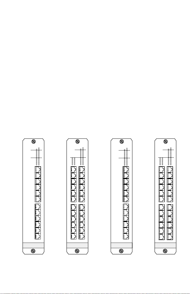
The TRXMIM models -22A / -24A / -42A / -44A, shown in Figure
1-1, comprise a family of active UTP/STP concentrators with port
switching capability for Token Ring networks. All four models are
designed for installation into any Cabletron Systems Multi Media
®
Access Center
(MMAC™) equipped with a Flexible Network Bus®
(FNB™). All four TRXMIMs are IEEE 802.5 compliant and IBM
compatible.
TRXMIM-22A
BYP
RING1-16Mb
RING2-16Mb
RING3-16Mb
RING4-16Mb
AUX1-16Mb
-PORTS-
SWITCHING UTP
TOKEN RING
ERR
MGNT
IN USE
IN USE
IN USE
IN USE
IN USE
IN USEAUX2-16Mb
71
82
93
104
115
126
1
X
2
X
3
X
4
X
5
X
6
X
7
X
8
X
9
X
10
X
11
X
12
X
TRXMIM-24A
BYP
RING1-16Mb
RING2-16Mb
RING3-16Mb
RING4-16Mb
AUX1-16Mb
19
13
20
14
21
15
22
16
23
17
24
18
-PORTS-
13
X
14
X
15
X
16
X
17
X
18
X
19
X
20
X
21
X
22
X
23
X
24
X
SWITCHING UTP
TOKEN RING
ERR
MGNT
IN USE
IN USE
IN USE
IN USE
IN USE
IN USEAUX2-16Mb
71
82
93
104
115
126
1
X
2
X
3
X
4
X
5
X
6
X
7
X
8
X
9
X
10
X
11
X
12
X
TRXMIM-42A
BYP
RING1-16Mb
RING2-16Mb
RING3-16Mb
RING4-16Mb
AUX1-16Mb
-PORTS-
SWITCHING STP
TOKEN RING
ERR
MGNT
IN USE
IN USE
IN USE
IN USE
IN USE
IN USEAUX2-16Mb
71
82
93
104
115
126
1
X
2
X
3
X
4
X
5
X
6
X
7
X
8
X
9
X
10
X
11
X
12
X
TRXMIM-44A
BYP
RING1-16Mb
RING2-16Mb
RING3-16Mb
RING4-16Mb
AUX1-16Mb
19
13
20
14
21
15
22
16
23
17
24
18
-PORTS-
13
X
14
X
15
X
16
X
17
X
18
X
19
X
20
X
21
X
22
X
23
X
24
X
SWITCHING STP
TOKEN RING
ERR
MGNT
IN USE
IN USE
IN USE
IN USE
IN USE
IN USEAUX2-16Mb
71
82
93
104
115
126
1
X
2
X
3
X
4
X
5
X
6
X
7
X
8
X
9
X
10
X
11
X
12
X
Figure 1-1. The TRXMIM-22A, TRXMIM-24A, TRXMIM-42A, and
TRXMIM-44A Token Ring Port Switching Concentrator Modules.
Page 1-1
Page 10

USING THIS MANUAL
1.1 USING THIS MANUAL
Prior to installing and operating the TRXMIM, please read through
this manual completely to become familiar with its contents and
with the features of the TRXMIM. If you are not familiar with port
switching and four-ring FNB applications, please begin by reading
A
Appendix A,
Introduction to Four-Ring FNB Functionality
.
general working knowledge of Token Ring (IEEE 802.5) networks is
helpful during installation.
Chapter 1,
Introduction
, describes how to use this document,
provides an overview of the features and capabilities of each
concentrator module, and concludes with a list of related manuals.
Chapter 2,
Installation Requirements & Specifications
, lists the
network requirements that must be met before installation, and
provides detailed specifications for each TRXMIM model.
Chapter 3,
installing the TRXMIM into a Multi Media Access Center
Installing the TRXMIM
, contains instructions for
®
(MMAC™) and attaching Token Ring station cabling.
Chapter 4,
Testing and Troubleshooting
, describes diagnostic
checks to assist in the correction of post-installation problems, and
provides detailed descriptions of LANVIEW®, Cabletron Systems’
built-in visual diagnostic and status monitoring system.
Appendix A,
Introduction to Four-Ring FNB Functionality,
discusses the concepts of port switching and port assignment.
1.2 ABOUT THE TRXMIM FAMILY
The TRXMIM family of concentrator modules provides MMAC
users with a new level of network connectivity. Their port
switching ability (fully described in Section 1.2.2,
Assignments and Port Switching
) expands the number Token
Port
Rings available within an MMAC and enables MMAC users to
switch ring connections between up to six Token Rings, without
changing a single cable connection. TRXMIMs also offer:
• complete compatibility with all Token Ring MIMs,
Page 1-2
Page 11

TCU Ports
• support for Cabletron Systems’ Automatic Beacon Recovery
Process (ABRP),
• automatic speed fault protection,
• active filtering, re-timing, and repeating circuitry on all ports,
• Multiple Ring Out connectivity for Passive MAU workgroups,
• and LANVIEW LEDs for “at-a-glance” diagnostic monitoring.
Note:
The TRXMIM only
assignments must be issued by a management module
executes
port switching. Port-switching
with
port-assigning capability, such as TRMM-2 or TRMM-4.
1.2.1 TCU Ports
Each TRXMIM is equipped with 12 or 24 TCU (Trunk Connector
Unit) ports, depending on the TRXMIM model (see Table 1-1). Each
TCU port is fitted with a female RJ-45 modular connector jack to
support the attachment of either STP (shielded twisted pair) or UTP
(unshielded twisted pair) cabling with RJ-45 connector plugs.
Models that support STP cabling use RJ-45 connectors that provide
a grounded connection for the cabling shield.
Table 1-1 Port and Media List for TRXMIM Models
TRXMIM-22A 12 - Unshielded RJ-45 ports
TRXMIM-24A 24 - Unshielded RJ-45 ports
TRXMIM-42A 12 - Shielded RJ-45 ports
TRXMIM-44A 24 - Shielded RJ-45 ports
Lobe Port and Ring Out Port Configurations
Each TCU port on the TRXMIM is internally defaulted to operate as
a lobe interface to support the insertion of a Token Ring station into
a ring. However, each TCU port may also be reconfigured, via the
Local Management (LM) application, to function as a Ring Out port
to support the connection of passive MAU (Multi-Station Access
Page 1-3
Page 12

ABOUT THE TRXMIM FAMILY
Unit) workgroups. See Section 1.2.4,
Workgroups
Active Circuitry
.
Support for Passive MAU
On each TCU port, TRXMIMs provide active circuitry which filters,
equalizes, and amplifies all received signals before transmitting
them to the next point on the ring. The result is enhanced signal
integrity and extended maximum station lobe cable distances.
Ring Speed Fault Protection
TRXMIMs also provide Ring Speed Fault Protection on each TCU
port to protect against beaconing conditions caused by stations
inserted at the wrong ring speed. The TRXMIM checks the ring
speeds of both the inserting station and the destination ring; if there
is a mismatch, the TRXMIM disables the port to keep the
misconfigured station isolated from the ring. The TRXMIM then
provides a simple visible LED signal to indicate to network
managers that Speed Fault Protection has disabled the port. The
port stays disabled until re-enabled by management. Refer to
Section 4.2,
LANVIEW LED SIGNALS
for information on the
LANVIEW LED visual status monitoring system.
1.2.2 Port Assignments and Port Switching
The TRXMIM requires the support of a port-assigning management
module (such as TRMM-2 or TRMM-4) to activate its port switching
functionality.
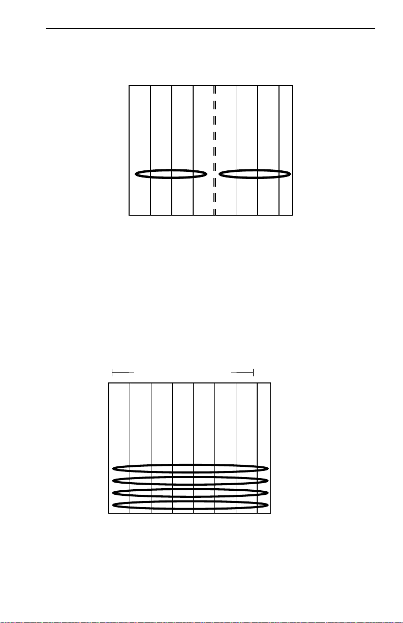
Without Port Switching
Without port-switching MIMs, MMAC users can create multiple
Token Ring LANs within an MMAC only by segmenting or
“wrapping” the FNB (as shown in Figure 1-2), and they can provide
access to only one ring segment from any one module. Thus, in
order to move a station from one ring to another, network
managers have to enter the wiring closet and physically move cable
connections from one module to another. With the advent of the
Page 1-4
Page 13
Port Assignments and Port Switching
Port-Switching MIMs
port-switching TRXMIM, Cabletron Systems offers alternative
solutions.
TRMM
TRMIM
FNB ring
segment A
FNB ring
segment B
TRMMIM
TRMIM
TRMIM
TRMIM
FNB ring wrapped at TRMMIM's right FNB interface.
TRMIM
TRMIM
Figure 1-2. FNB ring 1 segmented to form two LANs
With Port Switching
When controlled by a management module which supports port
switching, TRXMIMs and other port switching MIMs make use of
additional pins in their FNB connectors to create three additional
vertically stacked FNB rings as shown in Figure 1-3. The FNB itself
does not change, but these modules change the way it is used.
TRMM-4
TRXMIM
TRXMIM
TRXMIM
TRXMIM
TRXMIM
TDRMIM
TDRMIM
FNB ring 1
FNB ring 2
FNB ring 3
FNB ring 4
Figure 1-3. FNB Expanded to Four Rings by Port Switching MIMs
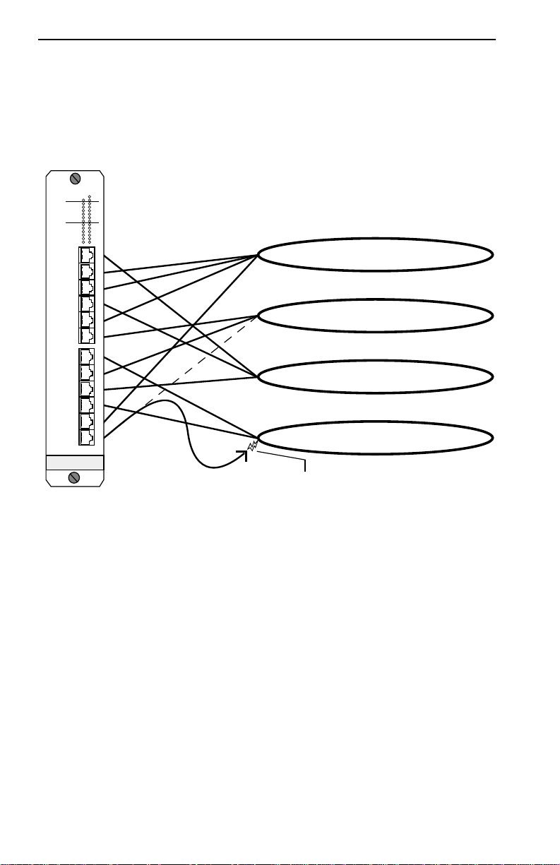
TRXMIMs are thus able to offer flexible network connectivity,
eliminating the need to change cable connections when switching
Page 1-5
Page 14
ABOUT THE TRXMIM FAMILY
4
stations from ring to ring. To move a station from one ring to
another, a user simply accesses the Local Management application
and issues a new port assignment. The TRXMIM then switches the
TCU’s port-to-ring connection internally, as illustrated in Figure
1-4, instantly connecting the station to the new ring.
TRXMIM-22A
BYP
RING1-16Mb
RING2-16Mb
RING3-16Mb
RING4-16Mb
AUX1-16Mb
-PORTS-
SWITCHING UTP
TOKEN RING
ERR
MGNT
made by Token Ring Management Module
IN USE
IN USE
IN USE
IN USE
IN USE
IN USEAUX2-16Mb
71
82
93
104
115
126
1
X
2
X
3
X
4
X
5
X
6
X
7
X
8
X
9
X
10
X
11
X
12
X
are executed internally by TRXMIM.
Port Assignments
FNB ring 1
FNB ring 2
FNB ring 3
FNB ring 4
Electronic reassignment of Port 12 from Ring 2 to Ring
Figure 1-4. Logical Model of Port Assignment and Port Switching
Auxiliary Rings
The TRXMIM also hosts two internal auxiliary rings which exist
only within the circuits of the TRXMIM module. Although these
“module-level” auxiliary rings do not have access to the FNB, they
function as complete, independent Token Rings within the module.
This brings the connectivity total to six Token Rings accessible from
any TRXMIM port: two isolated auxiliary rings within the module
itself, and four rings on the FNB which can be used to
intercommunicate with other stations/devices connected to the
same FNB rings via other MIMs in the hub.
Page 1-6
Page 15

Automatic Configuration at Power-Up
1.2.3 Automatic Configuration at Power-Up
The management module in the TRXMIM’s host MMAC stores all
user-configured port assignments in its NVRAM. Upon hub
start-up or TRXMIM reset, the management module reissues its
stored configurations to the TRXMIM so that all port assignments
set before power-down are reinstated at next power-up.
Some management modules, including the TRMM-2, also have
hardware jumpers or a switchblock to hold default ring speed
settings which are issued to all modules in the absence of
user-defined configurations stored in NVRAM.
If the TRXMIM receives no management-issued configuration
information at start-up (i.e. configuration settings from a
management module’s NVRAM are not available), the device uses
the configurations dictated by its hardware default settings.
Assignments from a management module always override the
TRXMIM’s hardware defaults.
Default Port Assignments
All TRXMIM TCU ports are assigned by default to FNB ring 1. This
default is not user-configurable.
Default Ring Speeds
The FNB ring 1 default ring speed is set by the position of the
Default Ring Speed Jumper. See Section 3.2.2,
Ring Speed Jumper
for configuration instructions.
Setting the Default
The default ring speed setting for all other rings (FNB rings 2 - 4
and Auxiliary rings 1 & 2) is 16 Mb/s. This default is not
user-configurable.
Management module defaults or NVRAM settings for ring speeds
override all TRXMIM hardware default ring speed settings. (The
TRMM-2, for example, has a switchblock on which ring speeds are
defined for the entire hub.) Consult the management module’s
manual for instructions on setting ring speeds throughout the hub.
Page 1-7
Page 16

ABOUT THE TRXMIM FAMILY
1.2.4 Support for Passive MAU Workgroups
Whereas a station signals a TCU to open its interface by sending a
phantom current down its lobe cable, a passive MAU can not
provide phantom current. A TCU Ring Out port is therefore
configured to ignore the absence of phantom current in the
connecting cable and to look instead for the presence of data bits to
determine link status.
By default, each of the TRXMIM’s TCU ports is configured to its
STN (station) setting to support concentrator lobe connections to
stations. Through Local Management, any TCU port may be
reconfigured to its RO (Ring Out) setting to support connections to
passive MAU (Multi-Station Access Unit) workgroups.
Note:
The output of the TRXMIM’s LANVIEW LEDs for a Ring Out
port is quite different from the output for a station lobe port. See Section
4.2,
LANVIEW LED SIGNALS
, for a discussion of this and all other
LED signal details.
Improved Protection from Beaconing
The TRXMIM provides enhanced reliability for existing networks
which use passive MAUs because Multiple Ring Out TCUs allow
for the separate attachment of each MAU. Rather than
daisy-chaining MAUs together as a single entity and risking their
collective isolation in case of beaconing, the user can now attach
each MAU individually, reducing the number of MAU ports that
are at risk of collective isolation in case of beaconing on the ring; the
TRXMIM’s Beacon Recovery system may bypass individually
connected MAUs on an individual rather than collective basis. See
Figure 1-5.
Page 1-8
Page 17
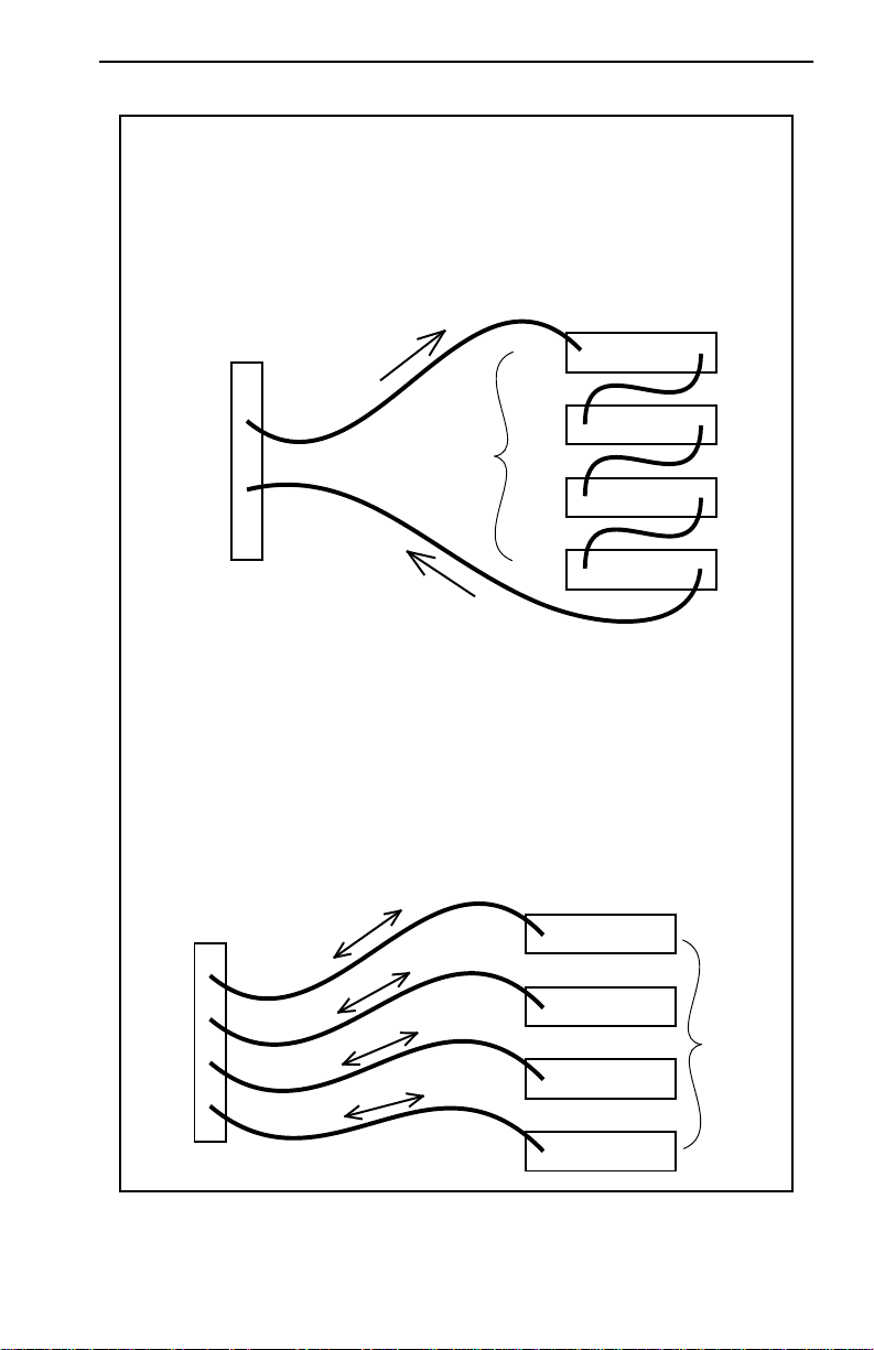
Support for Passive MAU Workgroups
COMMON MAU CONFIGURATION
When MAUs are daisy-chained,
they are connected as single collective entity.
The entire chain must be bypassed
to isolate the hub from a single beaconing station.
All stations lose connection if beaconing occurs on any station.
Ring
Out
Ring
Out
Ring
Out
Ring
Out
Ring
Out
Ring
In
MIM with
Ring
In
Ring
In
Ring
In
Access Units
Multi-Station
Ring
In
(8 Stations)
(8 Stations)
(8 Stations)
(8 Stations)
Ring In / Ring Out
TRXMIM MAU CONFIGURATION
When each MAU is individually connected to the TRXMIM,
only one MAU must be bypassed
to isolate the hub from a beaconing MAU station.
The 8 stations on that MAU still go down,
but the remaining MAUs and their stations stay operational.
Ring
Out
Ring
Out
Ring
Out
Ring
Out
TRXMIM
Ring
Ring
Ring
Ring
In
In
In
In
(8 Stations)
(8 Stations)
(8 Stations)
Multi-Station
(8 Stations)
Access Units
Figure 1-5. Improved Beacon Recovery Resolution for MAUs
Page 1-9
Page 18

ABOUT THE TRXMIM FAMILY
No Connection Redundancy
The TRXMIM MAU configuration does not provide for the MAU’s
redundant connection to the ring. In the common configuration, a
MAU chain is dual-attached to the Token Ring LAN via both a Ring
Out cable and a Ring In cable. Using a TCU port, however, each
passive MAU workgroup is physically connected to the hub in the
same manner as a station—by a single cable—and therefore is not
provided a backup path between the MAU and the Token Ring
network.
Only the dual attachment of Ring In
and
Ring Out cables can
provide a backup path. This level of connectivity must be provided
by Token Ring Repeater MIMs (such as TRRMIM or TDRMIM)
which are designed to extend trunk connections with full
redundancy.
1.2.5 Interaction with Other MIMs in the MMAC
Multiple concentrator modules can be installed into an MMAC to
increase the number of ports available on a Token Ring network.
Any TRXMIM installed within an MMAC may be connected to
other Token Ring MIMs, repeaters, bridges, and management
modules within the hub. When installed contiguously in the
MMAC and configured with identical ring speed settings, port
switching MIMs automatically attach to each other via the
continuous FNB rings on the backplane. If, however, a
management module issues wrapping commands, the specified
neighboring MIMs will wrap at their FNB interfaces, breaking the
FNB ring connections between them, and effectively segmenting
the FNB.
Note:
If the MMAC has a shunting FNB, vacant hub slots do not cause
breaks in FNB rings: the shunting FNB connectors on the backplane
provide a bypass circuit, maintaining ring continuity across vacant slots.
If the MMAC does not have a shunting FNB, vacant slots will force the
FNB rings to wrap, segmenting the FNB rings.
When port switching MIMs are interconnected, so are the
additional FNB rings they have each created at their FNB interfaces.
Page 1-10
Page 19

LANVIEW LEDs
Thus FNB rings 2, 3, and 4 are extended across the MMAC as far as
there are port switching modules to carry them. Port switching
MIMs are also compatible with earlier single-ring MIMs (e.g.
TRMIM) and will interconnect across FNB ring 1, but not across
FNB rings 2, 3, or 4. (Single-ring MIMs do not have port switching
capability and
cannot
support connections across FNB rings 2, 3, or
4.) For more explanation on four-ring FNB functionality, see
Appendix A,
Introduction to Four-Ring FNB Functionality
.
Note: It is recommended that all single-ring MIMs be grouped in
the left-most slots of the MMAC and all port switching MIMs be
grouped in the right-most slots
because any single-ring MIM installed
between port switching MIMs will break the continuity of FNB rings 2, 3,
4; and management modules that have direct FNB interfaces to FNB rings
2, 3, and 4 require contiguous contact with other port switching MIMs to
maintain ring continuity.
1.2.6 LANVIEW LEDs
The LANVIEW LED system is Cabletron Systems’ built-in,
“at-a-glance,” visual diagnostic and status monitoring system
which facilitates the quick diagnosis of physical layer network
problems. The LANVIEW LED system comprises several LEDs,
located on the front panel of the TRXMIM, which light, blink, and
flash in various colors to indicate various network and
module-specific conditions. The LANVIEW LED signal system is
discussed in detail in Section 4.2, LANVIEW LED SIGNALS.
1.2.7 Network Management
With a management module installed in slot 1 of the MMAC, the
TRXMIM and other modules in the hub can be monitored and
controlled by a variety of network management tools including
®
Cabletron Systems Local Management, Remote LANVIEW
®
Windows, and SPECTRUM
. Any Token Ring management
/
module may be used to manage the TRXMIM, but only a module
that supports port switching can activate the port-switching
functionality of the TRXMIM.
Page 1-11
Page 20

FURTHER INFORMATION
1.3 FURTHER INFORMATION
1.3.1 Related Manuals
The manuals listed below should be used to supplement the
procedures and other technical data provided in this manual. The
procedures in them will be referenced, where appropriate, but will
not be repeated.
Cabletron Systems TRMM-2 User’s Guide (PN 9031287)
Cabletron Systems TRMM-2 Local Management User’s Guide
(PN 9031389)
Cabletron Systems TDRMIM-22A/42A Token Ring Dual
Repeaters User’s Guide (PN 9031428)
1.3.2 Recommended Reading
The following publications are recommended if more information
is required regarding the implementation of Token Ring networks.
Local Area Networks, Token Ring Access Method, IEEE Standard
802.5 (1989)
Commercial Building Wiring Standard, EIA Standard Proposal
No. 1907-B (if approved, to be published as EIA/TIA-568)
LAN Troubleshooting Handbook, Mark Miller (1989, M&T
Publishing)
1.3.3 Getting Help
If you need additional support related to Cabletron Systems Token
Ring products, or if you have any questions, comments or
suggestions related to this manual, please contact Cabletron
Systems Technical Support:
By phone: (603) 332-9400
Monday-Friday; 8am - 8pm EST
Page 1-12
Page 21

By CompuServe®: GO CTRON from any ! prompt
By Internet mail: support@ctron.com
By Fax: (603) 337-3075
By BBS: (603) 337-3750
By mail: Cabletron Systems, Inc.
P.O. Box 5005
Rochester, NH 03866-5005
Getting Help
Page 1-13
Page 22

CHAPTER 2
INSTALLATION REQUIREMENTS &
SPECIFICATIONS OF OPERATION
Before attempting to install the TRXMIM, please review the
recommendations, requirements, and specifications which are
outlined in this chapter. Failure to follow these guidelines could
result in poor network performance.
2.1 GENERAL CABLING CONSIDERATIONS
Take care in planning and preparing the cabling and connections
for the network. The susceptibility of the LAN’s cables to crosstalk
and noise determines the network’s error rate, and thus, the
reliability of data propagation on the network. The quality of the
connections, the length of cables and other conditions of the
installation are critical factors in determining the reliability of the
network.
2.1.1 Network Performance Requirements
The overall cabling system used in a Token Ring network must
meet the following performance requirements:
Table 2-1. Token Ring Network Performance Requirements
Maximum
Total
Signal
Attenuation
Maximum
Total
Ambient
Noise
Minimum
NEXT
loss
per 100 m
≤ 14.5dB ≤ 20 dBmV ≥ 30.5 dB
All STP cables of IBM Type 1, 2, 6, and 9 meet Token Ring network
performance requirements. All category 5, all category 4, and some
category 3 (see Section 2.2.2, UTP Cable Lengths to Stations, on
Page 2-1
Page 23

GENERAL CABLING CONSIDERATIONS
page 5) UTP cables also meet these requirements. However, signal
integrity relies not only upon the quality of the cable but also upon
the quality of the connections. The connectors or terminators used
add considerable losses and may drive signal attenuation below
performance requirements. Choose and install connectors with
care.
Noise can be caused either by crosstalk or by externally imposed
influences. Crosstalk is interference caused by signal coupling
between the different cable pairs contained within a multi-pair
cable bundle; avoid mixing Token Ring signals with other
applications (voice, video, etc.) within the same cable. Outside
systems (motors, switching equipment, fluorescent lighting, high
amperage equipment) also may produce electrical interference and
cause noise. The number and quality of cable connections
contribute considerably to noise levels. If noise induced errors are
suspected, it may be necessary to re-route cabling away from
potential noise sources, or to ensure that the electrical wiring in the
area is properly wired and grounded, or to replace connectors
along affected segments.
Total attenuation is reduced by lobe length reductions, cable
upgrades, and connector improvements.
2.1.2 Installation Recommendations
In addition to complying with the cable specifications presented in
Sections 2.2 and 2.3, the cabling installation should comply with the
following recommendations to obtain optimum performance from
the network:
• UTP cabling should be free of splices, stubs, or bridged taps.
• No more than two punch-down blocks should exist between
TCU ports and wall outlets.
• Metal troughs, ducts, etc. carrying Token Ring signals should be
properly grounded.
• Cables should be routed away from sources of electrical noise,
such as power lines, fluorescent lights, electric motors, radio
interference, and heavy machinery.
Page 2-2
Page 24

Maximum Number of Stations
• Token Ring signals should not be routed through UTP cables
that exit a building or which are adjacent to cables either exiting
a building or exposed to lightning strikes and power surges.
• UTP cables that contain Token Ring signals should not be
simultaneously used for applications which may impress high
voltages (greater than 5 volts) with sharp rise or fall times, since
the noise coupling from such signals could directly cause errors
on the Token Ring network.
• For single telecommunications closet rings, lobe lengths should
not exceed 100 meters of 22 to 24 AWG wire from the attaching
device and the TCU port.
• Where practical, dedicated cable should be used for Token Ring
signals.
• Work area wall plates and outlets used for the Token Ring
network should be clearly labeled as Token Ring network lobe
connections.
2.1.3 Maximum Number of Stations
The maximum number of stations in a single ring, using STP lobe
cabling is 250 stations.
Although higher numbers are possible with better quality cabling,
when UTP lobe cabling is used anywhere on the ring, the
recommended limit is 150 stations.
2.2 UTP CABLING SPECIFICATIONS
Both UTP concentrator modules (TRXMIM-22A / 24A) support
D-inside wiring (DIW) voice grade Unshielded Twisted Pair (UTP)
cable as described in EIA SP-1907B and below. All category 5, all
category 4, and some (see Section 2.2.2, UTP Cable Lengths to
Stations, on page 5) category 3 UTP cables meet Token Ring
network performance requirements.
Page 2-3
Page 25

UTP CABLING SPECIFICATIONS
2.2.1 UTP Cable Categories
Both UTP concentrator modules (TRXMIM-22A / 24A) support
UTP cables classified as category 3, 4, and 5.
UTP cable is categorized according to the following specifications.
Table 2-2. UTP Cable Category Specifications
UTP
Cat.
Operating
Frequency
Electrical
Impedance
Signal
Attenuation
per 100m
NEXT
loss
(@ ≥100m)
4 MHz ≤ 100Ω ±15% ≤ 5.6 dB ≥ 32 dB
3
16 MHz ≤ 100Ω ±15% ≤ 13.1 dB ≥ 23 dB*
4 MHz ≤ 100Ω ±15% ≤ 4.3 dB ≥ 47 dB
4
16 MHz ≤ 100Ω ±15% ≤ 8.9 dB ≥ 38 dB
4 MHz ≤ 100Ω ±15% ≤ 4.3 dB ≥ 63 dB
5
16 MHz ≤ 100Ω ±15% ≤ 8.2 dB ≥ 44 dB
*below Token Ring performance requirement of ≥ 30.5 dB.
Category 3 consists of (usually) four Unshielded Twisted Pairs of
24 AWG solid wire for data or voice communication. (IBM Type 3
is coincidentally the same as UTP Category 3.) It is typically used to
wire cable runs within the walls of buildings. In some installations,
pre-existing UTP building wiring can be used for Token Ring
cabling.
WARNING: At 16 Mb/s ring speeds, some Category 3 cable does not meet
the performance requirements of a Token Ring network. This may impose
lower limits on lobe cable distances and ring node counts. See Table 2-2.
Categories 4 and 5 are higher quality versions of category 3. They
use the same gauge of wire but demonstrate superior performance
due to improvements in material quality and assembly (e.g. more
twists per foot).
Page 2-4
Page 26

UTP Cable Lengths to Stations
WARNING: Because Near-End Crosstalk (NEXT) contributes the
majority of its detrimental effects near the end of a lobe cable, the quality
of jumper cables and patch cables is most critical. Seek the highest practical
grade. The quality of connectors and terminators is also critical.
WARNING: Telephone Battery and Ringing voltages used in UTP
telephone circuits could present a shock hazard and can damage Token
Ring equipment if connected to Token Ring cabling. DO NOT connect
UTP cabling to any non-Token Ring network conductors (telephone,
etc.) or ground. If in doubt, test wiring before using.
2.2.2 UTP Cable Lengths to Stations
The physical length of the cable connecting a station to a TCU port
on the concentrator is referred to as the lobe length. The maximum
lobe length attainable with the concentrator, under ideal
conditions, is shown in Table 2-3. Cable routing, connector
attenuation, noise, and crosstalk can adversely affect the maximum
lobe length.
Table 2-3. UTP Maximum Lobe Lengths.
UTP
Category
Maximum Lengths
@ 4 Mb/s @ 16 Mb/s
meters (feet) meters (feet)
3 200 (656) 100* (328)*
4 225 (738) 110 (360)
5 250 (820) 120 (393)
*for cable with NEXT loss ≥ 30.5 dB per 100m
Some UTP category 3 cables fail to meet the performance
minimums required to support a Token Ring network. Whereas
category 3 allows for near end crosstalk (NEXT) loss as low as 23 dB
per 100 m at 16 Mb/s, Token Ring performance requirements
demand a NEXT loss of at least 30.5 dB. To safeguard against worst
case conditions (running at 16 Mb/s and using category 3 cable
with the category’s lowest qualifying NEXT loss--23 dB), the
Page 2-5
Page 27

STP CABLING SPECIFICATIONS
recommended maximum lobe length should be reduced to keep
crosstalk interference within acceptable levels when using
category 3 cable.
2.3 STP CABLING SPECIFICATIONS
Both STP concentrator modules (TRXMIM-42A / 44A) support all
STP cables classified as IBM Types 1, 2, 6, and 9. All cables meeting
the criteria for classification as IBM Type 1, 2, 6, or 9 meet Token
Ring network performance requirements.
2.3.1 STP Cable Categories
The supported STP cable types meet the following specifications:
Table 2-4. STP Cable Type Specifications.
IBM
Type
Operationa
l
Frequency
Impedance
Attenuation per...
1000 m (1000 ft)
4 MHz ≤ 150Ω ±15% ≤ 22 dB (≤ 6.7 dB)
1 & 2
16 MHz ≤ 150Ω ±15% ≤ 45 dB (≤ 13.7 dB)
4 MHz ≤ 150Ω ±15% ≤ 33 dB (≤ 10.0 dB)
6 & 9
16 MHz ≤ 150Ω ±15% ≤ 66 dB (≤ 20.0 dB)
IBM Type 1 consists of two shielded twisted pairs (STP) of 22 AWG
solid wire for data. Used for the longest cable runs within the walls
of buildings.
IBM Type 2 consists of six pairs of unshielded twisted pairs of 24
AWG solid wire and a shield casing. The two pairs carried within
the shield casing are used to carry Token Ring data. The four pairs
carried outside of the shield casing are typically used for voice
communication. Type 2 is frequently used to wire cable runs within
the walls of buildings.
Page 2-6
Page 28

STP Cable Lengths to Stations
IBM Type 6 consists of two STP of 26 AWG stranded wire for data.
Because of its high attenuation, Type 6 is used only in patch panels
or to connect devices to/from wall jacks. Attenuation for Type 6
cable is 3/2 x Type 1 cable (attenuation for 66 m of Type 6 =
attenuation for 100 m of Type 1).
IBM Type 9 is similar to Type 1, but uses 26 AWG solid wire. Like
Type 6, because of its high attenuation, Type 9 is used only in patch
panels or to connect devices to/from wall jacks. Attenuation for
Type 9 cable is 3/2 x Type 1 cable (66 m of Type 9 = 100 m of
Type 1).
2.3.2 STP Cable Lengths to Stations
The physical length of the cable connecting a station to a TCU port
on the concentrator is referred to as the lobe length. The maximum
lobe length attainable with the concentrator, under ideal
conditions, is shown in Table 2-5. Cable routing, connector
attenuation, noise and crosstalk can adversely affect the maximum
lobe length.
Table 2-5. STP Maximum Lobe Lengths.
STP
Types
Maximum Length
@ 4 Mb/s @ 16 Mb/s
meters(feet) meters(feet)
1 & 2 300 (984) 150 (492)
6 & 9 200 (656) 100 (328)
Mixed STP Cable Types
If cable types are to be mixed in the installation, compensations
must be made for the different cable attenuations. For example,
Type 6 & 9 cables can be run for only 2/3 the distance of Type 1:
100 meters (Type 1) ≈ 66 meters (Types 6, 9)
Page 2-7
Page 29

TRXMIM OPERATING SPECIFICATIONS
2.4 TRXMIM OPERATING SPECIFICATIONS
This section describes the operating specifications for each of the
active Token Ring concentrator modules. Cabletron Systems
reserves the right to change these specifications at any time without
notice.
2.4.1 Media Filters
When connecting Token Ring stations that are not equipped with a
Type 3 Media Filter to either of the active UTP concentrator
modules (TRXMIM-22A / 24A), a Type 3 Media Filter, such as the
Cabletron Systems TRMF or TRMF-2, must be installed in line with
the lobe cable at the Token Ring station connection.
2.4.2 Connector Types
The concentrator modules’ TCU ports are internally crossed-over to
provide connection of straight-through station lobe cabling via
female RJ-45 receptacles on the front panel. Figure 2-6 shows the
pinouts required for the mating (male) RJ-45 connectors for both
UTP and STP versions of the concentrator modules.
Page 2-8
Cable Shield*
8
7
TX+
RX–
RX+
TX–
6
5
4
3
2
1
MALE
RJ-45
*Cable Shield
not used
with UTP cabling
Cable Shield*
Figure 2-6. Concentrator Module TCU Port Pinouts.
Page 30

Ring Speeds
Each RJ-45 connector is encased in a metallic shield which provides
a means of connection for the STP cable shield. When STP patch
cable is used, shield continuity is maintained by contacts within the
female RJ-45 that contact the metallic casing of the male RJ-45 on the
STP lobe cabling.
Shielded patch cables that adapt a shielded RJ-45 to a Data
Connector (MIC) are available from Cabletron Systems in
eight-foot lengths. These adapter/patch cables permit connection
to an existing patch panel equipped with MICs. (See Figure 2-7)
Data Connector
(MIC)
TX+
O
B
TX–
R
G
Shield
RX+
RX–
Patch Panel/
Token Ring
Station
RXMIM-42A/44A
CU Port
TX+
TX–
RX+
RX–
Shield
RJ-45
6
3
4
5
Orange
Black
Red
Green
Shield
8 ft.
Figure 2-7. STP Adapter/Patch Cable (PN 9372057-8)
2.4.3 Ring Speeds
The default ring speed (for FNB ring 1), which is used in the
absence of configuration commands from a management module,
is selected by the position of the Default Ring Speed Jumper on the
board of the TRXMIM. The process for setting the default ring
speed for FNB 1 is defined and illustrated in Section 3.2.2, Setting
the Default Ring Speed Jumper. The TRXMIM default ring speeds
for FNB rings 2, 3, and 4 are permanently set at 16 Mb/s.
Note: All TRXMIM ring speed defaults are overridden by management
module commands.
Page 2-9
Page 31

TRXMIM OPERATING SPECIFICATIONS
2.4.4 Ring Sequence
When multiple Token Ring MIMs (set to the same ring speed) are
installed in adjacent slots within an MMAC, they are attached via
the FNB and create a larger ring network. Multiple Token Ring
MIMs are automatically attached (when possible) at power on, but
the configuration can be modified via network management
software, attaching or detaching adjacent MIMs.
The ring sequence for the stations on each ring (the order in which
stations are logically arranged on the ring) is determined by the
physical location of each station connection in the MMAC. It
progresses in ascending slot and port number order. There is a
separate ring sequence for each ring, and the sequence is changed
each time a station is inserted or de-inserted from a ring.
To determine the ring sequence, consider only those ports inserted
into the specified ring. Begin with the lowest numbered
(right-most) slot and list (in numerical order) each port inserted into
the ring. Repeatedly move to the next slot (one position to the left)
and list the inserted ports in numerical order until all ports inserted
into the ring have been listed. The order is continuous, wrapping
directly from the MMAC’s last inserted port to the first—from the
bottom of the list, right back to the top.
2.4.5 LANVIEW LEDs
There are a number LEDs on the front panel of each TRXMIM. With
the exception of the quantity of port-specific LEDs on each module,
all four TRXMIMs are equipped with the same indicators. Each
individually labelled LED uses a simple combination of colors and
ON/OFF states to provide information about its attributed
component. These components include ring speeds (16Mb) for each
ring, ring in use (IN USE) for each ring, module-level bypass (BYP),
module error (ERR), management (MGMT) or default mode, and
port status (PORT) for each port. The function of each LANVIEW
LED is discussed in detail in Section 4.2, LANVIEW LED
SIGNALS.
Page 2-10
Page 32

2.5 OTHER SPECIFICATIONS
2.5.1 Hardware Specifications
Ports: TRXMIM-22A / 42A: 12 RJ-45
TRXMIM-24A / 44A: 24 RJ-45
Backplane Connections: FNB rings 1 - 4
Cables Supported: TRXMIM-42A / 44A:
IBM Type 1, 2, 6, 9 (STP)
TRXMIM-22A / 24A:
EIA/TIA category 3, 4, 5 (UTP)
Physical
Dimensions: 11.5"H x 2"W x 13.4"D
2.5.2 Environmental Requirements
Hardware Specifications
Environmental Operating
Temperature: 5 to 40 C
Storage Temperature: -30 to 90 C
Relative Humidity: 5% to 95% non-condensing
2.5.3 Safety Issues
WARNING: It is the responsibility of the vendor of the system to which
the TRXMIM-22A/TRXMIM-24A/TRXMIM-42A/TRXMIM-44A will
be a part to ensure that the total system meets allowed limits of conducted
and radiated emissions.
This equipment is designed in accordance with UL478, UL910, NEC
725-2(b), CSA, IEC, TUV, VDE Class A, and meets FCC Part 15,
Class A limits.
Page 2-11
Page 33

OTHER SPECIFICATIONS
2.5.4 Service Projections
MTBF
(Mean Time Between Failure)
MTTR
(Mean Time To Repair)
TRXMIM-
22A/42A
TRXMIM-
24A/44A
592,098 hrs. 563,987 hrs.
< 0.5 hr. < 0.5 hr.
Page 2-12
Page 34

CHAPTER 3
INSTALLING THE TRXMIM
This chapter contains instructions for installing the TRXMIM into a
Cabletron Systems MMAC product and for connecting Token Ring
stations at the TRXMIM’s trunk coupling unit (TCU) ports.
3.1 GENERAL CONSIDERATIONS
If the TRXMIM is installed in a hub equipped with a management
module in Slot 1, TRXMIM jumper settings will be overridden by
settings provided by the management module. It is still
recommended, however, that the TRXMIM speed jumper be set, as
it will provide the default speed in the absence of a management
module.
Note: In the absence of a management module in the host MMAC to
provide port assignments, the ports of the TRXMIM will default to and
have access only to FNB ring 1.
Check that all requirements listed in Chapter 2, Installation
Requirements & Specifications, have been met before installing
and operating the TRXMIM. The following guidelines will be
helpful in properly configuring the system at installation:
• The TRXMIM can be installed into any slot in the MMAC except
the rightmost, Slot 1. This slot is reserved for specific
management/bridging/repeater modules such as TRMM-2.
• When the TRXMIM is being installed into an MMAC, be sure
that a Power Supply Module (PSM) is installed in the associated
power supply slot. The Power Supply Module is the source of
power for MMAC modules.
Note: A second power supply module is recommended for use with an
MMAC-8FNB for power supply redundancy.
Multiple Token Ring products, within an MMAC, are automatically
linked at power on, provided that the MMAC is configured with an
Page 3-1
Page 35

INSTALLATION
FNB, (either an MMAC-M3FNB, MMAC-M5FNB, or an
MMAC-M8FNB). Without the FNB, the individual MIMs will not
be linked, but rather will form independent Token Ring networks.
Note: The FNB is a full-height, full-width backplane that links Cabletron
Systems Token Ring products. MMAC-3s and MMAC-8s (without an
FNB) can be upgraded with an FNB, providing greater flexibility in
configuring the system. Contact Cabletron Systems Technical Support for
more information.
Establishing a network path between a Token Ring network and
another network type (i.e., FDDI or Ethernet) requires the use of a
bridging device.
3.2 INSTALLATION
Contact Cabletron Systems Technical Support immediately if you
encounter any problems unpacking or installing the module.
3.2.1 Unpacking the TRXMIM
Unpack and visually inspect the TRXMIM for damage:
CAUTION: Electrostatic Discharge (ESD) can damage the module.
Observe all precautions to prevent electrostatic discharges. When
handling the module, hold only the edges of the board or the metal front
panel. Avoid touching the components or surface of the board.
1. Carefully remove the TRXMIM from the shipping box. Save the
box and materials for possible future repackaging and
shipment.
2. Remove the TRXMIM from its protective plastic bag and set it
on top of its protective bag in a static free area. This will help to
prevent ESD damage.
Page 3-2
Page 36

Setting the Default Ring Speed Jumper
4 Mbit/sec
16 Mbit/sec
J1
Network Speed Jumper
Mother board
...
J1
Front
Panel
Daughter board
Figure 3-8. Default Ring Speed Jumper Settings.
3.2.2 Setting the Default Ring Speed Jumper
In the absence of a management module with port assigning
capability, the TRXMIM can not receive instructions to switch its
ports between rings, so all ports are defaulted to connect to FNB
Ring 1. The Default Ring Speed jumper provides the default ring
speed for FNB ring 1 only. FNB rings 2, 3, 4 and Auxiliary rings 1, 2
always default to 16 Mb/s.
• Position the jumper on the proper pins on the TRXMIM, as
illustrated in Figure 3-8, to select either 4 or 16 Mb/s as the
default network ring speed for FNB ring 1.
Note: The network speed is also selectable via the management module.
Management selections will override hardware jumper selections.
Note: The ring speed setting is a factor in determining maximum lobe
length. Refer to Chapter 2, Installation Requirements & Specifications for
additional information.
Page 3-3
Page 37

INSTALLATION
CONCENTRATOR MODULE
TRMM-2
SN
RESET
LWRP
CPU
NSRT
NSRT
16Mb
16Mb
XMT
XMT
RCV
RCV
R
I
N
TOKEN RING
G
TRXMIM-22A
1
RING1-16Mb
RING2-16Mb
RING3-16Mb
RING4-16Mb
AUX2-16Mb
S
T
AUX1-16Mb
A
T
I
O
N
C
O
M
1
C
O
M
2
SWITCHING UTP
TOKEN RING
ERR
MGNT
BYP
IN USE
IN USE
IN USE
IN USE
IN USE
IN USE
7
1
8
2
9
3
-PORTS10
4
11
5
12
6
1
X
2
X
3
X
4
X
5
X
6
X
7
X
8
X
9
X
10
X
11
X
12
X
KNURLED KNOBS
MMAC-M8FNB
BOARD SLOT 2
Figure 3-9. Installing the TRXMIM into the MMAC
3.2.3 Installing the TRXMIM into an MMAC
Note: The installer should be prepared to monitor the LANVIEW LEDs
as described in Section 3.2.4, Boot-up Check. Because the sequence may
proceed rapidly, please read Section 3.2.4 to prepare for this task before
installing the TRXMIM.
Note: Although the TRXMIM may be “hot swapped” when servicing,
Cabletron Systems recommends powering-down the hub before installing
any module, whenever practical.
Install the TRXMIM into the MMAC as follows:
1. Remove the coverplate from the selected MMAC slot and slide
the TRXMIM into the MMAC chassis (see Figure 3-9). Be sure
that the card is in the card guides at the top and bottom of the
chassis.
2. Secure the module to the MMAC by tightening the knurled
knobs. Failure to firmly secure the MIM may result in improper
operation.
The TRXMIM is now installed.
Page 3-4
Page 38

Boot-Up Check
3.2.4 Boot-Up Check
The chart below describes the LANVIEW LED activity for three
instances of TRXMIM operation. The first represents the moment of
power-on. The second and third both represent possible post
boot-up modes: management mode and default mode.
Because this is presented to assist in installation, it is assumed that
no lobe cables are attached to the TRXMIM at the moment of
power-up. For more detailed information on the significance of
LANVIEW LED activity, see Section 4.2, LANVIEW LED
SIGNALS.
Table 2-6. LANVIEW LED Activity at First Boot-up
After Default
boot-up
(management
module
not present)
LED label
at moment of
Power-on
After
Management
Module
boot-up
ERR (off) (off) (off)
BYP YELLOW YELLOW YELLOW
MGMT (off) GREEN (off)
Ring 1
16 Mb
Rings 2-4
& Aux 1-2
16 Mb
determined by
jumper
setting
YELLOW
determined by
management
assignment
determined by
management
assignments
determined by
jumper
setting
YELLOW
IN USE (all) (off) (off) (off)
Port (all) RED (off) (off)
When the Port LEDs turn from RED to off, start-up is complete.
Boot-up may take a few minutes. If the boot-up does not proceed as
described above, refer to Chapter 4, Testing and Troubleshooting.
Page 3-5
Page 39

INSTALLATION
The LED activity presented above represents a power-up with no cables
connected to the TRXMIM. See Section 4.2, LANVIEW LED SIGNALS,
to determine appropriate activity for other start-up conditions.
Because port assignments can be made only by a management
module, the TRXMIM goes through a bypass period at each
start-up to provide a time-window of opportunity during which a
management module may announce its intention to make these
assignments. During this start-up period, the TRXMIM holds itself
in full bypass mode by setting all ports to loop-back to prevent
them from connecting to any ring. After the start-up procedure is
complete--either the TRXMIM has been programmed by
management or has gone to default mode--the TRXMIM returns to
normal operations.
3.2.5 Connecting Lobe Cabling
The physical lobe connection from the TRXMIM to the Token
Ring station does not require the use of a crossover cable. To
provide the necessary signal crossover or null modem effect, the
TCU and Token Ring station connectors are wired so that the
transmit pair from the TRXMIM connects to the receive pair in the
station and the receive pair from the TRXMIM connects to the
transmit pair in the station. Table 3-1 provides a cross-reference of
pinouts for connections that may be encountered along the length
of lobe cabling.
Table 2-1. Lobe Cabling Connector / Signal Pinout Cross-reference
TX+ TX– RX+ RX–
RJ-11 6-pin
modular connector
RJ-45 8-pin
modular connector
Data Connector
(MIC) genderless
DB-9 9-pin
D-shell connector
Page 3-6
5234
6345
OBRG
9516
Page 40

Connecting Lobe Cabling
A Type 3 Media Filter must be used when connecting the UTP lobe
cable from either of the active UTP TRXMIMs (TRXMIM-22A/24A) to a
Token Ring station that is not equipped with an internal filter. A Type 3
Media Filter, such as the Cabletron Systems TRMF, provides impedance
matching from the Type 3 (UTP) lobe cabling to the Type 1 (STP) interface
provided with many Token Ring stations.
The lobe cabling used with the TRXMIM-42A/44A requires
shielded RJ-45 connections to attain the maximum lobe lengths
listed in Chapter 2, Installation Requirements & Specifications.
Shielded patch cables that adapt a shielded RJ-45 to a Data
Connector (MIC) are available from Cabletron Systems. These
adapter/patch cables permit connection to a pre-existing patch
panel equipped with data connectors (see Figure 3-10).
TRXMIM-22A/24A
TRXMIM-42A/44A
RX+
6
3
RX–
4
TX+
5
TX–
TCU port
RJ-45 jack
RX+
RX–
TX+
TX–
TCU port
RJ-45 jack
TX+
6
TX–
3
RX+
4
RX–
5
6
6
3
3
4
4
5
5
STP lobe cable
RJ-45 plug
UTP Lobe Cable
TX+
TX–
RX+
RX–
RJ-45 plugs
MIC coupling
TX+
TX–
RX+
RX–
ShieldShield
shield
TX+
TX–
RX+
RX–
O
O
B
B
R
R
G
G
MIC / MIC
6
TYPE 3
MEDIA
3
FILTER
(internal
4
or
external)
5
STP jumper cable
TX+
TX–
RX+
RX–
shield
Token Ring Station
TX+
9
5
TX–
RX+
1
6
RX–
NIC port
female DB-9
Token Ring Station
TX+
9
9
TX–
5
5
RX+
1
1
RX–
6
6
ShieldShield
Male DB-9 NIC port
Female DB-9
Figure 3-10. Token Ring Station Cable Wiring Schematic
Page 3-7
Page 41

INSTALLATION
Attaching Lobe Cabling at the Module
Twisted pair lobe cabling from Token Ring stations can be
connected to any TRXMIM port. To attach station cable at the
TRXMIM:
1. Insert the male RJ-45 connector from one end of the station’s
lobe cable or Type 3 patch cable into any TCU port (1X through
12X or 24X) on the front of the TRXMIM (see Figure 3-11).
2. If a patch panel is being used, attach the other end of the cable
to the appropriate patch panel jack.
3. Repeat these steps for each station.
Attaching Lobe Cabling at the Station
Connect stations to the TRXMIM using Type 3 patch cables. Attach
one end of the patch cable at the wall plate and the other to the
station port (see Figure 3-11).
NOTE: A Type 3 Media Filter must be installed at the station end
of the lobe cable when connecting UTP lobe cabling between an active
UTP TRXMIM and a Token Ring station without an internal filter.
Page 3-8
CONCENTRATOR MODULE
23
X
24
X
SWITCHING UTP
RJ-45
CONNECTOR
TOKEN RING
RJ-45 Port
STATION
CABLE
Figure 3-11. Connecting Stations to the TRXMIM.
Page 42

Pre-Operational Testing
3.2.6 Pre-Operational Testing
The TRXMIM should now be ready for operation. Before placing
the network into service, proceed to Chapter 4, Testing and
Troubleshooting and test the installation thoroughly to be sure
that all stations are able to be addressed and that data is being
relayed without error. Verify also that the networking software is
configured properly to match the installed network.
Page 3-9
Page 43

CHAPTER 4
TESTING AND TROUBLESHOOTING
This section contains procedures to verify that the connections
between the TRXMIM and the Token Ring stations are functioning
properly. A description of the LANVIEW LED system is also
provided.
4.1 INSTALLATION CHECKOUT
Perform the following check to confirm proper installation of the
TRXMIM:
1. Be sure that power settings for all connected Token Ring
stations and the MMAC match the AC power source (120 Vac
or 240 Vac) and are powered on.
2. Trace the ring path through the network to be sure that there are
no breaks in the ring and that it is free from logical design
errors. While tracing the ring:
a. Check each cable connection at the MIM.
b. Verify the pinouts for each connection.
c. Check all cable conductors for continuity. Cable testers are
available for this task.
d. Check that all cable connections at patch panels and wall
plates are secure.
3. Check network ring speeds:
a. Verify that ring speeds match the station and cable
specifications defined in Chapter 2, Installation
Requirements & Specifications.
b. Be sure that all devices in the ring network are set to the
same ring speed. Check all MIMs and stations in the
network.
Page 4-1
Page 44

LANVIEW LED SIGNALS
c. Check that the MIMs in the MMAC are grouped together
according to network type and ring capacity. For example,
all Ethernet MIMs together, all port switching Token Ring
MIMs together, all single-ring Token Ring MIMs together.
4. Confirm that the maximum cable length for EACH station and
the maximum number of stations are not exceeded.
When these checks have been successfully cleared, the TRXMIM is
ready for normal operation. If further problems are encountered,
contact Cabletron Systems Technical Support.
4.2 LANVIEW LED SIGNALS
LANVIEW is Cabletron Systems’ built-in visual diagnostic and
status monitoring system. Using LANVIEW, network trouble
shooting personnel can quickly scan the LANVIEW LEDs (shown
in Figure 4-12) to determine network status, diagnose network
problems, and isolate faulty nodes or trunk segments.
Page 4-2
TRXMIM-24A
RING1-16Mb
RING2-16Mb
RING3-16Mb
RING4-16Mb
AUX1-16Mb
19
13
20
14
21
15
22
16
23
17
24
18
-PORTS-
13
X
BYP
ERR
MGMT
IN USE
IN USE
IN USE
IN USE
IN USE
IN USEAUX2-16Mb
71
82
93
104
115
126
1
X
Figure 4-12. TRXMIM LANVIEW LEDs
Page 45

LANVIEW LED Definitions Table
4.2.1 LANVIEW LED Definitions Table
The locations shown and the following definitions apply to
LANVIEW LEDs of all four TRXMIMs (model -24A is shown in the
figure), except that ports 13 through 24 and the LEDs associated
with them are not present on the TRXMIM-22A and TRXMIM-42A.
Table 4-1: LANVIEW LED Status Descriptions
LED LED status Meaning
(off) Normal operation
ERR
RED Hardware Error condition
BYP YELLOW No ports inserted in FNB rings
(off) Internal default settings in effect.*
MGMT
GREEN
TRXMIM has been configured
by management module
(off) Ring speed set to 4Mb/s
16Mb
YELLOW Ring speed set to 16Mb/s
(off) No ports inserted in ring
IN USE
GREEN At least one port inserted in ring
Blinking GREEN
At least one port is inserted, but
the ring is bypassed from FNB
(off) Port enabled, but not linked
GREEN Port inserted (enabled and linked)
PORT
Blinking GREEN
but disabled by management
Port linked,
Blinking RED Speed Fault on linked port
RED Port disabled and not linked
*TRXMIM internal defaults: All ports assigned to FNB ring 1. Ring
speed set according to position of Default Ring Speed Jumper.
Page 4-3
Page 46

LANVIEW LED SIGNALS
Note: “Linked” describes an electromechanical connection between a
concentrator module’s TCU port and a station. “Inserted” describes a data
connection between a station and a LAN (via the concentrator module).
4.2.2 ERR - Error
This LED should not turn on during normal operations. When lit,
this RED LED indicates a hardware failure within the module. If
this occurs, contact Cabletron Systems Technical Support.
4.2.3 BYP - Bypass
When lit, this YELLOW LED indicates that no ports are inserted into
the FNB rings. This occurs under the following conditions:
The module is executing normal start-up procedure.
At start-up, the TRXMIM will hold all of its ports in
loopback while it awaits configuration settings from a
management module. After the TRXMIM completes its
start-up procedure--either the TRXMIM has been
programmed by management or has gone to default
mode--all ports will be switched to appropriate rings and
bypass will be dependent on the following conditions.
No ports are linked to the TRXMIM.
All lobe ports are without phantom current and all Ring Out
ports are without data. There is nothing to signal the TCUs
to open.
Ports are linked, but directly bypassed.
Phantom or data is present, but management has issued
bypass commands to the specific ports to keep the TCUs
closed
Ports are linked, but the rings are bypassed from the FNB.
If the ports are not directly bypassed by management, they
are inserted into rings on the TRXMIM. However, when
TRXMIM rings are bypassed from the FNB by management
Page 4-4
Page 47

MGMT - Management Mode
command, they operate as isolated rings, just like the
Auxiliary rings.
Bypass mode does not necessarily mean that the TRXMIM
is devoid of network activity. Even if all FNB channels are
bypassed from the backplane, the TRXMIM may host up to
six active LANs.
Management has placed the entire module in bypass mode.
This is effectively the same as the previous condition. The
TRXMIM may still host LANs, but these LANs will not be in
communication with the FNB. All rings on the TRXMIM are
isolated.
4.2.4 MGMT - Management Mode
When this LED is OFF during normal operations, the TRXMIM is
operating in default mode (no management control): all lobe ports
assigned to FNB ring 1 with FNB ring 1 speed set according to the
Default Ring Speed Jumper.
This LED may also be OFF during normal boot-up before
communications have been established between the TRXMIM and
a management module.
When this LED is GREEN, the TRXMIM has received configuration
information (such as port assignments and ring speeds) from a
management module in slot 1. Configuration settings such as port
assignment are stored in the management module’s NVRAM and
communicated to TRXMIM at power-on so that the configurations
set for the TRXMIM in one session will carry over to the next.
4.2.5 16MB - Ring Speed
This LED indicates the rings speed of the corresponding ring. OFF
indicates 4 Mb/s and YELLOW indicates 16 Mb/s.
The default mode ring speed for FNB ring 1 is determined by the
Default Ring Speed Jumper setting. The ring speed default is 16
MB/s for all other FNB and Auxiliary rings. Default ring speed
Page 4-5
Page 48

LANVIEW LED SIGNALS
assignments take effect immediately at start-up, but are relevant
only if the module boots into default mode. In default mode,
although the LEDs will be YELLOW for FNB rings 2, 3, 4 and Aux
rings 1, 2, the rings will still be inaccessible.
In management mode, all ring speeds are set by the management
module.
4.2.6 IN USE - Ring In Use
This LED indicates the status of network communication on the
associated TRXMIM ring. It does not reflect ring activity that
excludes this TRXMIM (e.g. on rings bypassed from the TRXMIM).
If the LED is:
OFF,
no ports are inserted into the associated ring.
GREEN,
at least one port on the module is successfully inserted into
the associated ring.
BLINKING GREEN,
at least one port is inserted into the ring, but the ring itself is
bypassed from the FNB by management command.
Because Auxiliary rings are never attached to the FNB, their
IN USE LEDs do not go to BLINKING GREEN.
Because passive MAUs are inserted only when actually
passing data, they may cause the LED to appear to flash
intermittently rather than blink consistently.
Page 4-6
Page 49

PORT - Port Status
4.2.7 PORT - Port Status
This LED indicates the status of the connection at the TCU.
If at power-on, the LED for any port is:
RED,
the port is disabled.
At power on, all ports are looped back (disabled) until the
module comes out of bypass mode and returns to normal
operations.
cycling between GREEN and RED,
phantom current is present at the disabled port.
The port insertion is being suspended until the module
comes out of bypass mode and returns to normal
operations. When the TRXMIM is ready, the ports will be
switched to their respective rings and all suspended ports
will be inserted into those rings.
If, during normal operation, the LED for a lobe port is:
GREEN,
the port is inserted into its assigned ring.
BLINKING GREEN,
a Token Ring station is phantom linked to the port, but the
port is disabled by management command.
BLINKING RED,
a Speed Fault was detected (a station was trying to insert
into the ring at the wrong ring speed) and the port has been
looped back to prevent mis-insertion and beaconing.
RED,
the port is disabled by management command.
Page 4-7
Page 50

LANVIEW LED SIGNALS
If, during normal operation, the LED for a Ring Out port is:
GREEN,
the Ring Out port is active (carrying data) and inserted into
the ring.
BLINKING RED,
the Ring Out port is in a normal inactive state.
This is equivalent to OFF for a lobe port during normal
operation. Refer to Section 1.2.4, Support for Passive MAU
Workgroups, for an explanation of the operational
difference between a Ring Out port and a lobe port.
RED,
the port is disabled by management command.
Page 4-8
Page 51

APPENDIX A
INTRODUCTION TO FOUR-RING
FNB FUNCTIONALITY
A.1 Introduction
This appendix addresses only Token Ring network applications. It
is intended to introduce and explain the closely related concepts of
port switching and the four-ring Flexible Network Bus (FNB).
These concepts reflect recent developments essential to the basic
functionality of a number of Cabletron products. An understanding
of these concepts is essential to the full operation of all port
switching Token Ring Media Interface Modules (e.g., TRXMIM,
TDRMIM) and all Management Modules (e.g., TRMM-2) that
support port switching.
A.2 The Flexible Network Bus (FNB)
The FNB is a data bus which spans the entire width of the
backplane of the Multi Media Access Center (MMAC), providing
Ring In / Ring Out connections between each module and forming
continuous channels for the inter-communication of data between
modules within the MMAC.
A.3 FNB Operations Without Port Switching
Creation of Multiple FNB Rings
In normal Token Ring applications, when using Media Interface
Modules (MIMs) that do not support port switching (such as
TRMIM and TRRMIM), the FNB serves as a single Token Ring
LAN. Each Media Interface Module (MIM) in the MMAC may
attach to this single LAN and operate together; or MIMs with left/
Page A-1
Page 52

FNB Operations Without Port Switching
A
Port-Switching MIMs
right-wrapping abilities may “wrap” (bypass) their Ring In /Ring
Out connections, effectively segmenting the FNB into two or more
smaller, isolated Token Ring LANs, as illustrated in Figure A-1.
TRMM
TRMIM
FNB ring
segment
FNB ring
segment B
TRMMIM
TRMIM
TRMIM
TRMIM
FNB ring wrapped at TRMMIM's right FNB interface.
TRMIM
TRMIM
Figure A-1. FNB segmentation produces two isolated FNB rings
TRMM-4
TRXMIM
TRXMIM
TRXMIM
TRXMIM
TRXMIM
TDRMIM
TDRMIM
Page A-2
FNB ring 1
FNB ring 2
FNB ring 3
FNB ring 4
Figure A-2. Four vertically stacked FNB rings
Page 53

FNB Operations With Port Switching
Management of Segmented FNB Rings
If the FNB is segmented, as shown in Figure A-1, the modules on
one segment are isolated from modules on another FNB segment;
management interfaces with one ring are isolated from other FNB
segments as well. Therefore, to receive full management support,
each FNB segment requires its own management interface; but as
management modules are added to the MMAC to manage these
rings, the number of slots available for concentrator modules is
decreased, creating greater power demands, and increasing the
overall cost per port in the MMAC.
A.4 FNB Operations With Port Switching
Each single-ring MIM (e.g., TRMIM) provides access to only one
FNB ring; all concentrator ports are permanently assigned to
connect to FNB ring 1. Each port-switching MIM (e.g., TRXMIM),
however, makes use of additional pins in its FNB connector to
create four vertically stacked, parallel FNB rings (as illustrated in
Figure A-2). With simultaneous access to four rings, port-switching
MIMs assign each of their concentrator ports on an individual basis
to connect to any of four FNB rings, providing multiple users with
access to multiple rings. Refer to Figure A-3 for a comparative
illustration of the connectivity afforded by each kind of MIM.
Port Assignment and Port Switching
Port assignments are made via the Local Management application
provided with port-assigning management modules. The
re-assignment or switching of a port from one ring to another
requires no physical reconfiguration of lobe cables: port-switching
MIM users assign concentrator ports on an individual basis to
connect to any of the four FNB rings and the connection is changed
internally by the port-switching MIM (as represented in Figure
A-4). Note, however, that without the use of a management
module, there are no means for switching port assignments: all
ports are assigned by default to FNB ring 1.
Page A-3
Page 54

FNB Operations With Port Switching
TRMIMs
TRXMIMs
1
2
3
4
4
TRMIM
TRMIM
TRMIM
TRMIM
TRXMIM
TRXMIM
TRXMIM
TRMM-2
Segmented
FNB ring 1
TRXMIM-22A
BYP
RING1-16Mb
RING2-16Mb
RING3-16Mb
RING4-16Mb
AUX1-16Mb
-PORTS-
SWITCHING UTP
TOKEN RING
ERR
MGNT
IN USE
IN USE
IN USE
IN USE
IN USE
IN USEAUX2-16Mb
71
82
93
104
115
126
1
X
2
X
3
X
4
X
5
X
6
X
7
X
8
X
9
X
10
X
11
X
12
X
FNB ring
FNB ring
FNB ring
FNB ring
Figure A-3. Mixed MIMs
Port Assignments
made by Token Ring Management Module
are executed internally by TRXMIM.
FNB ring 1
FNB ring 2
FNB ring 3
Electronic reassignment of Port 12 from Ring 2 to Ring
FNB ring 4
Page A-4
Figure A-4. Port Assignment and Port Switching
Page 55

Configuration Specifications
Management
For a management module to fully manage a ring, it requires a
network-monitoring interface with the ring. Whereas single-ring
management modules have only one network interface,
port-assigning management modules provide for multiple ring
interfaces, making it possible for a single management module to
fully manage any or all of the rings in the hub. (The TRMM-2 can
manage two Token Rings and the TRMM-4 can manage four.) This
leaves all other hub slots available for concentrator modules,
eliminating the power demands of additional management
modules, and actually reducing the overall cost per port in the
MMAC. Meanwhile, port switching increases the number of Token
Rings in the hub and makes them easier to access.
New Terminology
The four vertically stacked FNB rings are now referred to as FNB
rings 1, 2, 3, and 4. FNB ring 1 is the same ring that has connected
all earlier generation, single-ring MIMs (e.g., TRMIM), and was
addressed in earlier manuals as “the FNB ring,” or simply “the
FNB.” The term “the FNB” now refers collectively to the channels
and connectors of the MMAC backplane’s communications bus
which supports FNB rings, interconnects MIMs, and carries all
user-data.
A.5 Configuration Specifications
Single-ring MIMs and port switching MIMs are compatible and
interconnectable across FNB ring 1. However, as shown in Figure
A-3, single-ring MIMs cannot support communications across FNB
rings 2, 3, or 4. If installed in a slot between port switching MIMs, a
single-ring MIM will isolate the additional FNB rings established
on either side of the single-ring MIM; this configuration is not
recommended. All port switching MIMs should be grouped together
in the right-most slots of the MMAC as shown in Figure A-3.
Single-ring MIMs still have the ability to segment FNB ring 1 (as
shown in Figure A-3). They still view the FNB as having only one
Page A-5
Page 56

Configuration Specifications
ring and are not affected by the utilization of FNB rings 2, 3, or 4 by
other MIMs in the MMAC.
Port switching MIMs do not have the ability to wrap (segment) the
FNB; they are automatically and internally connected to the MIMs
adjacent to them via the MMAC chassis. However, a neighboring
single-ring MIM may wrap the connection between itself and a
port-switching MIM to isolate the port-switching MIMs from other
MIMs in the hub.
Page A-6
 Loading...