

Cabletron Systems TRRMIM-2AT, TRRMIM-F2T, TRRMIM-F3T, TRRMIM-4AT, TRRMIM-AT Installation Manual
Page 1

TRRMIM-AT, TRRMIM-2A T, TRRMIM-4A T
The Complete Networking Solution™
TRRMIM-F2T & TRRMIM-F3T
ACTIVE TOKEN RING
REPEATER MODULES
INSTALLATION GUIDE
CABLETRON SYSTEMS, P. O. Box 5005, Rochester, NH 03867-5005
Page 2

NOTICE
NOTICE
Cabletron Systems reserves the right to make changes in
specifications and other information contained in this document
without prior notice. The reader should in all cases consult
Cabletron Systems to determine whether any such changes have
been made.
The hardware, firmware, or software described in this manual is
subject to change without notice.
IN NO EVENT SHALL CABLETRON SYSTEMS BE LIABLE FOR
ANY INCIDENTAL, INDIRECT, SPECIAL, OR
CONSEQUENTIAL DAMAGES WHATSOEVER (INCLUDING
BUT NOT LIMITED TO LOST PROFITS) ARISING OUT OF OR
RELATED TO THIS MANUAL OR THE INFORMATION
CONTAINED IN IT, EVEN IF CABLETRON SYSTEMS HAS BEEN
ADVISED OF, KNOWN, OR SHOULD HAVE KNOWN, THE
POSSIBILITY OF SUCH DAMAGES.
© Copyright July 1993 by:
Cabletron Systems Inc.
P.O. Box 5005
Rochester NH 03867-0505
All Rights Reserved
Printed in the United States of America
Order Number: 9030502-01 July 93
TRRMIM-AT, TRRMIM-2AT, TRRMIM-4AT, TRRMIM-F2T,
TRRMIM-F3T
, and
MMAC
are trademarks of
Cabletron Systems, Inc.
LANVIEW
and
Remote LANVIEW
, are registered trademarks of
Cabletron Systems, Inc.
IBM
is a registered trademark of International Business Machines
Corporation.
i
Page 3

NOTICE
FCC NOTICE
This device complies with Part 15 of the FCC rules. Operation is
subject to the following two conditions: (1) this device may not
cause harmful interference, and (2) this device must accept any
interference received, including interference that may cause
undesired operation.
NOTE:
This equipment has been tested and found to comply with
the limits for a Class A digital device, pursuant to Part 15 of the FCC
rules. These limits are designed to provide reasonable protection
against harmful interference when the equipment is operated in a
commercial environment. This equipment uses, generates, and can
radiate radio frequency energy and if not installed in accordance
with the operator’s manual, may cause harmful interference to
radio communications. Operation of this equipment in a residential
area is likely to cause interference in which case the user will be
required to correct the interference at his own expense.
WARNING:
Changes or modifications made to this device which
are not expressly approved by the party responsible for compliance
could void the user’s authority to operate the equipment.
DOC NOTICE
This digital apparatus does not exceed the Class A limits for radio
noise emissions from digital apparatus set out in the Radio
Interference Regulations of the Canadian Department of
Communications.
Le présent appareil numérique n’émet pas de bruits
radioélectriques dépassant les limites applicables aux appareils
numériques de la class A prescrites dans le Règlement sur le
brouillage radioélectrique édicté par le ministère des
Communications du Canada.
ii
Page 4

CONTENTS
CONTENTS
CHAPTER 1 INTRODUCTION
1.1 Using this Manual........................................................................ 1-1
1.2 The TRRMIM ................................................................................ 1-2
1.2.1 The TRRMIM -AT, TRRMIM-2AT and TRRMIM-4AT 1-3
1.2.2 The TRRMIM-F2T and TRRMIM-F3T ............................ 1-5
1.3 Ring-in Ring-out Connections.................................................... 1-6
1.4 Related Manuals........................................................................... 1-7
1.5 Recommended Reading .............................................................. 1-7
1.6 Getting Help ................................................................................. 1-8
CHAPTER 2 INSTALLATION REQUIREMENTS
SPECIFICATIONS
2.1 Network Requirements............................................................... 2-1
2.1.1 Cable Specifications........................................................... 2-1
2.1.2 Trunk Cable Lengths......................................................... 2-9
2.1.3 Cabling Recommendations ............................................ 2-10
2.1.4 Temperature ..................................................................... 2-12
2.2 Maximum Number of Stations................................................. 2-12
2.3 Operating Specifications ........................................................... 2-12
2.3.1 Ring Speed........................................................................ 2-12
2.3.2 Ring Sequence .................................................................. 2-13
2.3.3 LANVIEW LEDs.............................................................. 2-14
2.3.4 Connectors........................................................................ 2-17
2.3.5 General Specifications..................................................... 2-20
CHAPTER 3 INSTALLING THE REPEATER
3.1 Unpacking the Repeater.............................................................. 3-1
3.2 Setting the Default Ring Speed .................................................. 3-2
iii
Page 5

CONTENTS
3.3 Installing the Repeater into a MMAC........................................3-3
3.4 Attaching Trunk Cables to the Repeater...................................3-4
3.5 UTP AND STP LOBE CABLING................................................3-4
3.5.1 Attaching Stations to the TRRMIM-2AT ........................3-6
3.5.2 Attaching Stations to the TRRMIM-4AT ........................3-8
3.6 Fiber Optic Lode Cabling ............................................................3-9
3.7 Ring-in Ring-out Ports (TPIM) .................................................3-11
3.8 Finishing the Installation...........................................................3-13
CHAPTER 4 TESTING AND TROUBLESHOOTING
4.1 Installation Check-out..................................................................4-1
4.2 Using LANVIEW..........................................................................4-2
iv
Page 6

CHAPTER 1
INTRODUCTION
INTRODUCTION
Welcome to the
TRRMIM-AT, TRRMIM-2AT, TRRMIM-4AT,
TRRMIM-F2T, & TRRMIM-F3T Active Token Ring Repeater
Modules Installation Guide
. This installation guide serves as a
reference for installing and troubleshooting the Cabletron Systems
token ring repeaters models: TRRMIM-AT, TRRMIM-2AT,
TRRMIM-4AT, TRRMIM-F2T, and TRRMIM-F3T.
The TRRMIMs are designed for installation into a Cabletron
Systems Multi Media Access Center (MMAC). The repeaters are
IEEE 802.5 compliant and can be installed to create an independent
token ring network or connected to other token ring devices and
expand existing networks.
NOTE:
The term
repeater
is used throughout this manual to describe
features and functions that are common to all repeater/MIMs. The terms
TRRMIM-AT, TRRMIM-2AT, TRRMIM-4AT, TRRMIM-F2T, and
TRRMIM-F3T are only used when it is necessary to describe features that
are unique to a specific device.
1.1 USING THIS MANUAL
Prior to installing and operating your repeater, read through this
manual completely to familiarize yourself with its contents and to
gain an understanding of the features of both repeaters. A general
working knowledge of Token Ring (IEEE 802.5) networks will be
helpful when installing the repeater.
Chapter 1,
Introduction
, describes the features and capabilities of
the TRRMIMs, lists related manuals, and recommended reading.
Chapter 2,
Installation Requirements/Specifications
, lists
specifications for the TRRMIMs and describes other network
requirements that must be met before you install your token ring
repeater.
Page 1-1
Page 7

INTRODUCTION
Chapter 3,
Installing the Repeater
, gives instructions for installing
a token ring repeater into an MMAC, connecting stations, and
inserting the repeater into a token ring network.
Chapter 4,
Testing and Troubleshooting
, describes testing and
troubleshooting the installation of the TRRMIM and covers using
®
LANVIEW
, Cabletron Systems built-in visual diagnostic and
status monitoring system.
1.2 THE TRRMIM
The TRRMIM (see Figure 1-1) is a 802.5 compliant token ring
repeater, designed for installation into a Cabletron Systems Multi
Media Access Center (MMAC) that is equipped with a Flexible
Network Bus™ (FNB). In addition to functioning as a repeater, the
module can serve multiple functions when installed in an MMAC.
Externally accessible Ring-In and Ring-Out ports, provided by the
plug-in Token Ring Port Interface Modules (TPIM), may use either
fiber optic, unshielded twisted pair (UTP), or shielded twisted pair
(STP) cabling. Ring connections are also made via the MMAC
Flexible Network Bus, allowing other MIMs to be a part of the ring.
Both the internal and external ring connections are active
connections and provide regeneration, reshaping and retiming of
both the main and backup signal paths.
Since the TPIM Ring-In and Ring-Out ports on the repeaters allow
connection of either fiber optic or STP cabling, they can be
configured to function as a copper to fiber optic
converter
.
The repeaters can be set to operate at ring speeds of either
4 Mbit/sec or 16 Mbit/sec. All equipment in a single ring network
must be set to the same ring speed. They cannot be mixed.
To connect two networks with different ring speeds, a bridging
device must be installed.
Repeaters installed in an MMAC (equipped with an FNB) and
MIMs operating with same MAC layer protocol (Token Ring/
Page 1-2
Page 8

INTRODUCTION
802.5) and link speed (4 Mbit/s or 16 Mbit/s) can be linked, via the
FNB, into a single token ring network. Multiple MMACs can be
connected via the externally accessible Ring-In/Ring-Out ports of
the repeater.
Any SNMP manager can be used to control and monitor these
repeaters when a management module (TRMM, TRMMIM, or
TRBMIM) is installed in the MMAC. Management packages such as
Cabletron Systems Local Management, Remote LANVIEW/
®
Windows
, and SPECTRUM® may be used.
LANVIEW LEDs are visible at the front panel of the repeaters
showing the status of several operational functions of the repeaters.
LANVIEW is a useful tool for quickly diagnosing physical layer
problems.
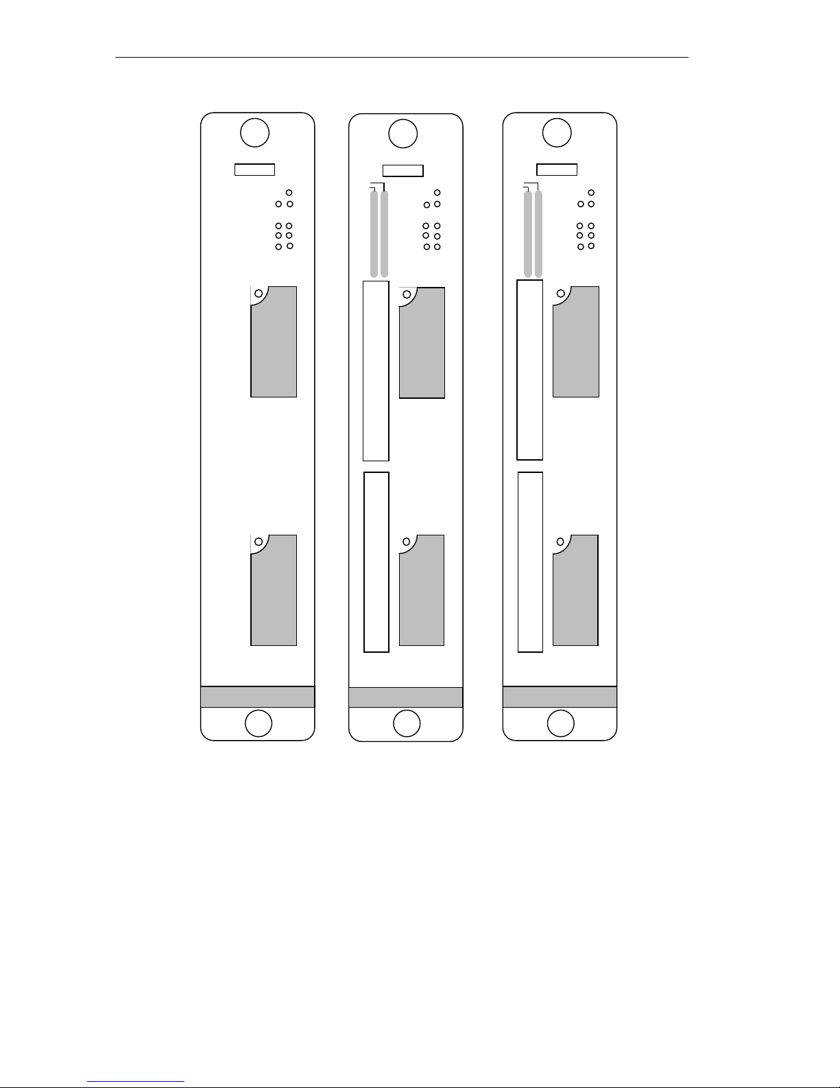
1.2.1 The TRRMIM -AT, TRRMIM-2AT and TRRMIM-4AT
The TRRMIM-AT, TRRMIM-2AT, and TRRMIM-4AT have two
front panel TPIMs for Ring-in and Ring-out connections
(see Figure 1-1). A variety of media types are supported.
Page 1-3
Page 9
INTRODUCTION
TRRMIM-AT
RI
TRRMIM-2AT
LNK
ERR
16 MBMGMT
RO
CRS16
PEN
AWEN
R
I
T
P
I
M
R
O
T
P
I
M
PEN
1
2
3
4
5
6
7
8
9
10
11
12
1
X
2
X
3
X
4
X
5
X
6
X
7
X
8
X
9
X
10
X
11
X
12
X
RI RO
ERR
16 MBMGMT
CRS16
PEN
AWEN
R
I
T
P
I
M
R
O
T
P
I
M
TRRMIM-4AT
LNK
PEN
1
2
3
4
5
6
7
8
9
10
11
12
1
X
2
X
3
X
4
X
5
X
6
X
7
X
8
X
9
X
10
X
11
X
12
X
ERR
16 MBMGMT
RO
RI
CRS16
PEN
AWEN
R
I
T
P
I
M
R
O
T
P
I
M
Figure 1-1 The TRRMIM-AT, -2AT, and -4AT
The TRRMIM-2AT provides twelve active unshielded RJ-45
connectors supporting unshielded twisted pair (UTP) station (lobe)
cabling. These ports support voice grade unshielded twisted pair
(UTP) and IBM Type 3 UTP cable.
Page 1-4
Page 10

INTRODUCTION
The TRRMIM-4AT provides twelve active shielded RJ-45 TCU
ports supporting Shielded twisted pair (STP) cabling. These ports
support IBM Type 1, 2, 6 and 9 shielded twisted pair cable.
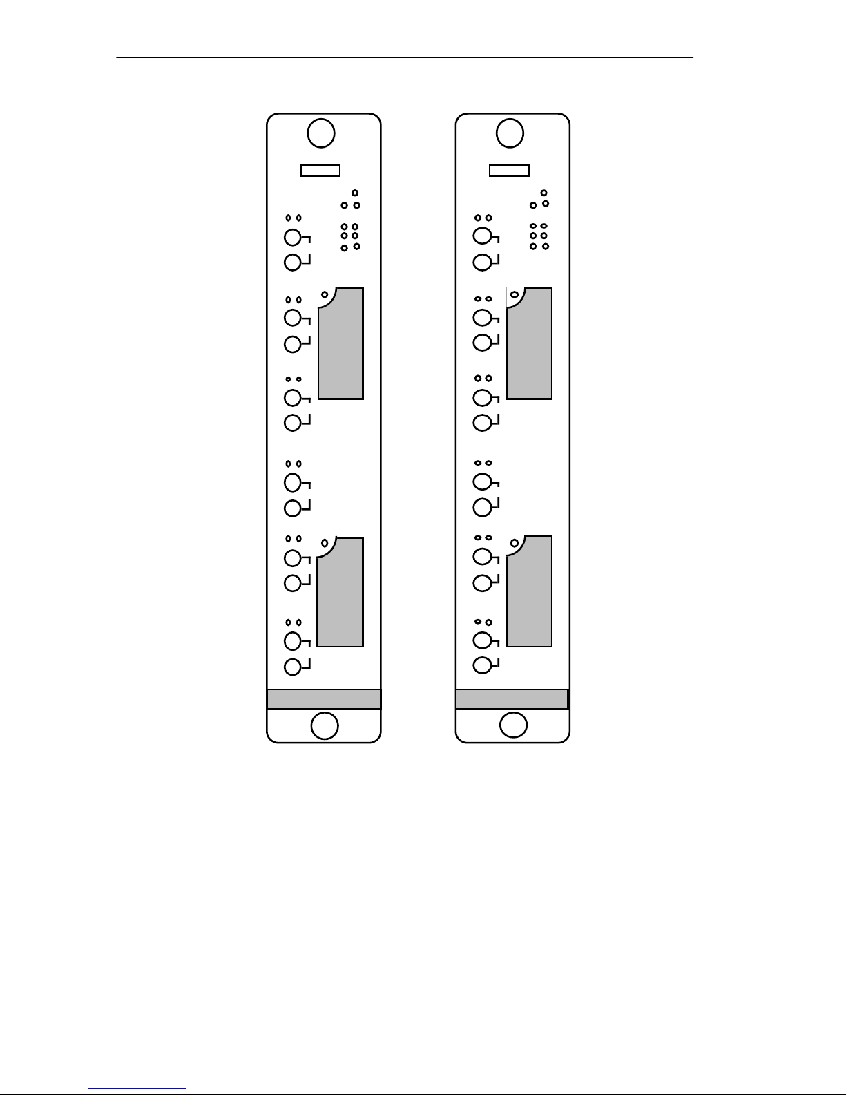
1.2.2 The TRRMIM-F2T and TRRMIM-F3T
The TRRMIM-F2T, and TRRMIM-F3T have two front panel TPIMs
for Ring-in and Ring-out connections (see Figure 1-2). A variety of
media types are supported.
Both repeaters provide six fiber optic ports for station (lobe)
cabling. The TRRMIM-F2T supports multimode fiber optic cable
and the TRRMIM-F3T support single mode cable for the lobe
connections.
Page 1-5
Page 11
INTRODUCTION
TRRMIM-F2T
FLNK
INS
TX
1
RX
FLNK
INS
TX
2
RX
FLNK
INS
TX
3
RX
FLNK
INS
TX
4
RX
FLNK
INS
TX
5
RX
FLNK
INS
TX
6
RX
RI RO
ERR
16 MBMGMT
CRS16
PEN
AWEN
TRRMIM-F3T
ERR
FLNK
INS
TX
1
RX
FLNK
R
I
T
P
I
M
TX
RX
TX
INS
2
FLNK
INS
3
RX
FLNK
INS
TX
4
RX
FLNK
INS
R
O
T
P
I
M
TX
RX
TX
5
FLNK
INS
6
RX
16 MBMGMT
RO
RI
CRS16
PEN
AWEN
R
I
T
P
I
M
R
O
T
P
I
M
Figure 1-2 The TRRMIM-F2T and TRRMIM-F3T
1.3 RING-IN RING-OUT CONNECTIONS
TPIMs are used for the Ring-in and Ring-out connections and
provide for many types of media. Table 1-1 lists the available
TPIMs.
Page 1-6
Page 12

INTRODUCTION
Table 1-1 Available TPIMs
TPIM Media Type Connector
TPIM-T1 Shielded Twisted P air DB9
TPIM-T2 Unshielded Twisted P air RJ-45
TPIM-T4 Shielded Twisted P air RJ-45
TPIM-F2 Multi-mode Fiber Optic ST
TPIM-F3 Single mode Fiber Optic ST
1.4 RELATED MANUALS
The manuals listed below should be used to supplement the
procedures and other technical data provided in this manual. The
procedures in them will be referenced, where appropriate, but will
not be repeated.
Cabletron Systems
Multi Media Access Center Overview and Set
Up Guide
Cabletron Systems
Token Ring Local Management for the
Cabletron Systems TRMM
1.5 RECOMMENDED READING
The following publications are recommended if more information
is required on implementing a Token Ring network.
Local Area Networks, Token Ring Access Method
, IEEE Standard
802.5
Commercial Building Wiring Standard
No. 1907-B
(if approved, to be published as
, EIA Standard Proposal
EIA/TIA-568
)
Page 1-7
Page 13

INTRODUCTION
LAN Troubleshooting Handbook
, Mark Miller (1989, M&T
Publishing, Inc.)
1.6 GETTING HELP
If you need additional support related to the Cabletron Systems
Token Ring products, or if you have any questions, comments or
suggestions related to this manual, please contact Cabletron
Systems Technical Support at:
Cabletron Systems, Inc.
P. O. Box 5005
Rochester, NH 03867-0505
Phone: (603) 332-9400
Page 1-8
Page 14

REQUIREMENTS/SPECIFICATIONS
CHAPTER 2
INSTALLATION
REQUIREMENTS/SPECIFICATIONS
This chapter defines the requirements for other network elements
that will work with your token ring repeater and describes the
operational specifications for the TRRMIM-AT, TRRMIM-2AT
TRRMIM-4AT, TRRMIM-F2T, and TRRMIM-F3T. Before installing
your repeater, review the requirements and specifications that are
outlined in this chapter.
All conditions, guidelines, specifications, and requirements
included in this chapter must be satisfied to achieve optimum
performance from this equipment. Failure to follow these
guidelines may result in unsatisfactory network performance.
2.1 NETWORK REQUIREMENTS
Take care in planning and preparing the cabling and connections
for your network. The quality of the connections, the length of
cables and other conditions of the installation are critical factors in
determining the reliability of your network. The following are the
network requirements to operate this equipment.
2.1.1 Cable Specifications
Trunk Cabling
fiber, or multi-mode fiber, depending upon the TPIM used.
Lobe Cabling
specific repeater:
• The TRRMIM-2AT supports voice grade UTP cable, as
described in EIA Standard Proposal No. 1907-B, and IBM Type
3 (and category 4 and 5) UTP cabling on its twelve trunk
coupling unit (TCU) ports.
- The repeaters support UTP, STP, single-mode
- The media used for lobe cabling depends on your
Page 2-1
Page 15

REQUIREMENTS/SPECIFICATIONS
• The TRRMIM-4AT supports IBM shielded twisted pair (STP)
cable Types 1, 2, 6, and 9 on its twelve trunk coupling unit
(TCU) ports.
• The TRRMIM-F2T supports multi-mode fiber optic cables using
ST connectors.
• The TRRMIM-F3T supports single-mode fiber optic cable using
ST style connectors.
STP CABLE TYPES
The TRRMIM-4AT, TPIM-T1 and TPIM-T4 support IBM Type 1, 2,
6, and 9 STP cabling as described in Table 2-1. STP cabling must
conform to the limits shown in Table 2-2.
Page 2-2
Page 16

REQUIREMENTS/SPECIFICATIONS
Table 2-1 IBM Cable Types
Type 1 Two shielded twisted pairs (STP) of 22 AWG solid wire for
data. Used for the longest cable runs within the walls of
buildings.
Type 2 Similar to Type 1 data cable, but having four additional
unshielded twisted pairs of 22 AWG solid wire. These are
carried outside of the shield casing and are typically used
for voice communication. Frequently used to wire cable
runs within the walls of buildings.
Type 6 Two STP of 26 AWG stranded wire for data. This type is
used in patch panels or to connect devices to/from wall
jacks. Attenuation for Type 6 cable is 3/2 x Type 1 cable
(66 m of Type 6 = 100 meters of Type 1).
Type 9 Similar to Type 1, but uses 26 AWG solid wire. Attenuation
for Type 9 cable is 3/2 x Type 1 cable (66 m of Type 9 =
100 meters of Type 1).
Attenuation and Impedance
The maximum attenuation for specific STP cable types is shown in
Table 2-2. The attenuation values include the attenuation of the
cables, connectors, patch panels, and reflection losses due to
impedance mismatches in the segment.
Table 2-2 STP Cable Specifications
Frequency Impedance Attenuation
Types 1 & 2
4 Mhz
16 Mhz
Type 6 & 9
4 Mhz
16 Mhz
150Ω ±15%
150Ω ±15%
150Ω ±15%
150Ω ±15%
<22 dB/km (6.7 dB/1000 ft.)
<45 dB/km (13.7 dB/1000 ft)
<33 dB/km (10 dB/1000 ft.)
<66 dB/km (20 dB/1000 ft)
Page 2-3
Page 17

REQUIREMENTS/SPECIFICATIONS
MAXIMUM CABLE LENGTH
Two cable lengths are defined for the repeaters,
Trunk Length
Lobe Length
.
- The lobe length is the physical length of the cable
Lobe Length
and
connecting a station to its TCU port at the repeater. Table 2-3 shows
the maximum lobe length, according to ring speed for each
repeater. The cable lengths listed in the table a total length of the
cable that is made up of a single cable type.
Trunk Length
- The maximum trunk cable length between
repeaters or between a repeater and another active device is equal
to the maximum drive distance (refer to Table 2-4). When the
neighboring token ring device is a passive device, the combined
length of the connecting trunk cable and twice the longest lobe
cable attached to the passive ring segment cannot exceed the
maximum drive distance.
Table 2-3 Maximum Lobe Length
STP
Cable Type
IBM Types 1 & 2
IBM Type 6 & 9
(only for station to
wall jack and patch
panels)
Maximum Lobe Length
4 Mbit/s 16 Mbit/s
300 meters 150 meters
(984 feet) (492 feet)
200 meters 100 meters
(656 feet) (328 feet)
Page 2-4
Page 18

Table 2-4 Maximum Drive Distance
Cable Type
REQUIREMENTS/SPECIFICATIONS
Ring Speed
4 Mbit/s 16 Mbit/s
STP (Types 1 & 2)
STP (Types 6 & 9)
770 meters 346 meters
(2525 feet) (1138 feet)
513 meters 230 meters
(1683 feet) (755 feet)
UTP CABLE TYPES
The TRRMIM-2AT and the TPIM-T2 support D-inside wiring
(DIW) voice grade Unshielded Twisted Pair (UTP) cable as
described in
EIA SP-1907B
. Voice grade UTP cabling (e.g., IBM
Type 3 UTP) must conform to the limits shown in Table 2-3.
The increased popularity and cost advantages of UTP cable have
driven refinements to UTP cable design. As a result, better grades
of UTP cable, known as supergrade or level 4, are becoming
available that exhibit improved transmission characteristics. These
improved grades of UTP can often be used to permit operation at
16 Mbit/sec on longer lobe cables.
Attenuation and Impedance
The maximum attenuation for UTP cabling is shown in Table 2-5.
The values listed include the attenuation of the cables, connectors,
patch panels, and reflection losses due to impedance mismatches in
the segment.
Page 2-5
Page 19

REQUIREMENTS/SPECIFICATIONS
Table 2-5 UTP Voice Grade (IBM Type 3) Specifications
Frequency Impedance Attenuation
1 Mhz 100Ω ±15% <26 dB/km (8 dB/1000 ft)
4 Mhz 100Ω ±15% <56 dB/km (16 dB/1000 ft)
10 Mhz 100Ω ±15% <98 dB/km (30 dB/1000 ft)
16 Mhz 100Ω ±15% <131 dB/km (40 dB/1000 ft)
NOTE:
IBM Type 3 - Consists of four Unshielded Twisted Pairs of 24
AWG solid wire for data or voice communication and is typically used to
wire cable runs within the walls of buildings.
In some installations, existing UTP building wiring can be used for
token ring cabling.
DO NOT
connect UTP cabling to any non-token
ring network conductors (telephone, etc.) or ground. If in doubt,
test wiring before using.
WARNING:
Telephone Battery and Ringing voltages, used in UTP
telephone circuits, could present a shock hazard and can damage token
ring equipment when connected to token ring cabling.
MAXIMUM CABLE LENGTH
Lobe Length
is the physical length of the cable connecting a station
to its TCU port at the repeater. Table 2-6 shows the maximum lobe
length, according to ring speed for each repeater. The cable lengths
listed in the table show a total length of the cable that is made up of
a single cable type.
Page 2-6
Page 20

Table 2-6 Maximum Lobe Length
Cable Type
UTP
Category 3
Category 4
Category 5
Type 3 Media Filter
REQUIREMENTS/SPECIFICATIONS
Maximum Lobe Length
4 Mbit/s 16 Mbit/s
150 meters 85 meters
(492 feet) (279 feet)
200 meters 100 meters
(656 feet) (328 feet)
250 meters 120 meters
(820 feet) (394 feet)
When connecting token ring devices that are not equipped with a
Type 3 Media Filter to a UTP port, a Type 3 Media Filter, such as the
Cabletron Systems TRMF or TRMF-2, must be installed in line with
the lobe cable at the connection to token ring station.
Multi-Mode Fiber Optic Network Requirements
When connecting a Fiber Optic Link Segment to TRRMIM-F2T or a
TPIM-F2, the following network requirements must be met:
• Cable Type - The cable must be one of the following multimode fiber optic media:
- 50/125 µm fiber optic cabling.
- 62.5/125 µm fiber optic cabling.
- 100/140 µm fiber optic cabling.
• Attenuation - The fiber optic cable must be tested with a fiber
optic attenuation test set that is adjusted for an 850 nm
wavelength. This test verifies that the signal loss in a cable is
within an acceptable level:
Page 2-7
Page 21

REQUIREMENTS/SPECIFICATIONS
- 13.0 dB or less for 50/125 fiber cable segment.
- 16.0 dB or less for 62.5/125 fiber cable segment.
- 19.0 dB or less for 100/140 fiber cable segment.
• Budget and Propagation Delay - When determining the
maximum fiber optic cable length, the fiber optic budget delay
and total network propagation should be calculated and taken
into consideration before fiber optic cable runs are incorporated
in any network design. Fiber optic budget is the combination of
the optical loss due to the fiber optic cable, in-line splices, and
fiber optic connectors. Propagation delay is the amount of time
it takes a packet to travel from the sending device to the
receiving device.
• Length - The maximum allowable fiber optic cable length is
2 km.
Single-Mode Fiber Optic Network Requirements
When connecting a single-mode fiber optic link segment to a
TRRMIM-F3T or a TPIM-F3, the following network requirements
must be met:
• The fiber optic link segment should consist of 8/125 - 12/125
µm single mode µm fiber optic cabling. You can also use 62.5/
125 µm multimode cable, however optical loss will be greater
with multimode cable and distances will be limited to 2 km.
• The fiber optic cable must be tested with a fiber optic
attenuation test set that is adjusted for a 1300 nm wave length.
This test verifies that the signal loss in a cable is within an
acceptable level of 10.0 dB or less for any given single mode
fiber optic link.
• When determining the maximum fiber optic cable length, the
fiber optic budget (total loss of 10.0 dB or less between stations)
and total network propagation delay should be calculated and
considered before fiber runs are incorporated in any network
design.
Page 2-8
Page 22

REQUIREMENTS/SPECIFICATIONS
• Fiber optic budget is the combination of the optical loss due to
the fiber optic cable, in-line splices, and fiber optic connectors
(the loss for each splice and connector is typically 1 dB or less).
• Propagation delay is the amount of time it takes a packet to
travel from the sending device to the receiving device. Total
propagation delay allowed for the entire network is 25.6 µsec. If
the total propagation delay between any two nodes on the
network exceeds 25.6 µsec, then bridges should be used.
• When using single mode fiber optic cable, segment lengths up
to 10 km are possible if system budgets are met. However, the
IEEE 802.5J specification allows for a maximum length of 2 km.
2.1.2 Trunk Cable Lengths
The maximum trunk cable length between repeaters or between a
repeater and another active device is equal to the maximum drive
distance (refer to Table 2-7). When the neighboring token ring
device is a passive device, the combined length of the connecting
trunk cable and twice the longest lobe cable attached to the passive
ring segment cannot exceed the maximum drive distance.
Table 2-7 Maximum Drive Distance
Ring Speed
Cable Type
Fiber Optic - Multi-mode 2 kilometers 2 kilometers
(6562 feet) (6562 feet)
4 Mbit/s 16 Mbit/s
Page 2-9
Page 23

REQUIREMENTS/SPECIFICATIONS
Mixed Cable Types - If you mix cable types in your installation,
you must compensate for the different cable attenuations. Type 6
and Type 9 cables can be run for only 2/3 the distance of Type 1.
This means:
10 meters (Type 1) ≈ 6.6 meters (Types 6, 9)
Example: Maximum Length for Mixed Cabling Installation
-- 16 Mbit/sec ring speed and 130 stations.
-- The building has 60 meters of Type 1 cable in the wall.
-- How much Type 6 cable is available to connect the repeater
TCU port to the patch panel and the station to the local wall
jack?
-- Type 6 can only go 2/3 the distance of Type 1.
Solution:
100 meters = maximum cable length if only Type 1 cable is used
[60 meters of Type 1] + [40 meters of Type 1] = max. length
[60 meters of Type 1] + [(0.66) x (40 meters) of Type 6 ] = max.
length
|
|
26.4 meters of Type 6
(for patch panel and wall jack connections)
2.1.3 Cabling Recommendations
Crosstalk, noise, and the number and quality of connections
determine reliable data propagation and your network’s error rate.
Crosstalk is interference caused by signal coupling between the
different cable pairs contained within a multi-pair cable bundle.
Multi-pair cables should not be used for UTP lobe cabling. STP lobe
cabling should be dedicated to carrying token ring traffic. Avoid
mixing token ring signals with other applications (voice, etc.)
within the same cable.
Noise can be caused by either crosstalk or externally induced
impulses. If noise induced errors are suspected, it may be necessary
to re-route cabling away from potential noise sources (motors,
switching equipment, fluorescent lighting, high amperage
Page 2-10
Page 24

REQUIREMENTS/SPECIFICATIONS
equipment), or to ensure that the electrical wiring in the area is
properly wired and grounded.
In addition to complying with the preceding cable specifications,
the following recommendations should be followed to minimize
errors and help to obtain optimum performance from your
network:
• UTP cabling should be free of splices, stubs or bridged taps.
• No more than two punch-down blocks between TCU ports and
wall outlets.
• Metal troughs, ducts, etc. carrying token ring signals should be
properly grounded.
• Route cables away from sources of electrical noise, such as:
a. Power lines
b. Fluorescent lights
c. Electric motors
d. Radio interference
e. Heavy machinery.
• Token ring signals should not be routed through UTP cables
that exit a building or which are adjacent to cables either exiting
a building or exposed to lightning strikes and power surges.
• UTP cables that contain token ring signals should not be
simultaneously used for applications which may impress high
voltages (greater than 5 volts) with sharp rise or fall times, since
the noise coupling from such signals could directly cause errors
on the token ring network.
• For single telecommunications closet rings, lobe lengths should
not exceed 100 meters or 22 to 24 AWG wire from the attaching
device and the TCU port.
Page 2-11
Page 25

REQUIREMENTS/SPECIFICATIONS
• When possible, use dedicated UTP cable for token ring signals.
2.1.4 Temperature
The attenuation of PVC insulated cable varies significantly with
temperature. Plenum-rated cables are strongly recommended at
temperatures greater than 40° C to ensure that cable attenuation
remains within specification. Check the cable manufacturer’s
specifications.
2.2 MAXIMUM NUMBER OF STATIONS
The maximum number of stations attached to a single token ring
network is determined by the type of media used for lobe cabling
within the network. For networks using only STP lobe cabling, the
maximum number of stations is 250. The maximum number of
stations when UTP cabling is used anywhere in a network is 150.
These limits apply for both 4 Mbit/sec and 16 Mbit/sec ring
speeds.
2.3 OPERATING SPECIFICATIONS
This section lists the operating specifications for the repeaters.
Cabletron Systems reserves the right to change these specifications
at any time without notice.
2.3.1 Ring Speed
Cabletron Systems token ring repeaters can be operated at a ring
speed of either 4 Mbit/s or 16 Mbit/s. The default ring speed is set
by a hardware jumper on the repeater board (refer to Chapter 3,
Installing the Repeater, to set the default ring speed). The default
ring speed setting can be overridden via network management
software (refer to the applicable Local Management User’s Guide).
Page 2-12
Page 26

REQUIREMENTS/SPECIFICATIONS
2.3.2 Ring Sequence
When multiple token ring boards (set to the same ring speed) are
installed in adjacent slots within an MMAC, they can be attached
via the FNB to create a larger ring network. The default
configuration for a token ring repeater automatically links it to the
boards in the adjacent slots at power on. However, the
configuration can be modified via network management software,
attaching or detaching adjacent boards, thus creating separate rings
or changing ring configurations.
When a repeater is installed, the ring sequence starts at the
externally accessible Ring-In port. If the repeater is detached from
other token ring boards (by software, incompatible ring speed or
empty adjacent slots), the ring sequence is restricted to the repeater
and goes from the Ring-In port to each of the TCU ports, in
ascending port number order, and then out the Ring-Out port.
When multiple token ring boards are installed in consecutive slots
and attached via the FNB, the sequence is in ascending slot number
order. When the repeater is attached via the FNB to other token ring
boards, the ring sequence begins at the Ring-In port of the repeater,
threads through the TCU ports on the repeater and is routed out,
via the FNB, to the next (higher slot number) token ring board on
the bus. An empty slot or non-token ring board causes the FNB
trunk connection to loop back to the first token ring board in the
sequence. From there it continues to thread through the Token Ring
boards and TCU ports until it returns to the repeater, and finally to
the Ring-Out port.
Example: TRMIM-22 in slot 1 with ports 2, 5, 8, & 12 in use.
TRRMIM-2AT in slot 2 with ports 1, 2, 3, and 5 in use.
TRMIM-22 in slot 3 with ports 1, 5, 7, 11, & 12 in use.
An FNB is installed in the MMAC.
All three boards are attached via the FNB.
The ring sequence for this example is from Slot 2, Ring-In port
to ports 1, 2, 3, and 5, then out the FNB to Slot 3, ports 1, 5, 7, 11,
Page 2-13
Page 27

REQUIREMENTS/SPECIFICATIONS
12, via the FNB to Slot 1 ports 2, 5, 8, 12. It then returns to Slot 2
and out the Ring-Out port of the TRRMIM-2AT.
For the ring order of other Cabletron Systems Token Ring products,
refer to the specific product manuals.
2.3.3 LANVIEW LEDs
The LANVIEW LEDs, their locations, and functions are the same
for the three repeaters. Their locations are illustrated on the
TRRMIM-2AT in Figure 2-1. Definitions for the LANVIEW LEDs on
the front panel of the repeaters are listed in Table 2-8.
The TPIMs also have a LNK (Link) LED on their front panel which
lights when Phantom current is received at that port.
Page 2-14
Page 28

REQUIREMENTS/SPECIFICATIONS
MGMT
LNK
PEN
TRRMIM-2AT
LNK
PEN
1
2
3
4
5
6
7
8
9
10
11
12
TRRMIM-F2T and F3T only
FLNK
ERR
16 MBMGMT
RI RO
CRS16
PEN
AWEN
ERR
16MB
CRS16
PEN
AWEN
FLNK
INS
1
INS
Figure 2-1 LANVIEW LED Locations
Page 2-15
Page 29

REQUIREMENTS/SPECIFICATIONS
g
g
s
Table 2-8 LANVIEW LED Description
Label Color Description
ERR Red Error or Speed Fault detected
ON Hardware error detected
OFF Normal operation
Flashing Software detected recoverable error
16 Mb Yellow Ring Speed Indicator
ON 16 Mbit/s mode selected
OFF 4 Mbit/s mode selected
MGMT Green Management
ON Repeater is set for Management Mode
OFF Repeater is in AUTO Mode
LNK Green Link Attached (One LED for each port)
ON Indicates that Phantom voltage is being
sensed at the respective TCU port.
OFF Indicates that Phantom voltage is not bein
sensed at the respective TCU port.
PEN Yellow Port Enabled
ON The associated port is enabled
OFF The associated port is disabled
Blinking Device attempting to connect at the wron
ring speed
CRS16 Yellow 16 Mbit/s carrier sensed
ON 16 Mbit/s carrier sensed at the
respective trunk port
OFF 4 Mbit/s carrier sensed at the
respective trunk port
AWEN Yellow Auto Wrap enabled
ON Ring-In/Ring-Out port set to wrap mode
OFF No Autowrap capability (non Cabletron
products)
FLNK Green Fiber Optic Link
ON Respective Fiber Optic lobe port is
receiving (link established)
OFF Respective Fiber Optic lobe port is not
receiving a signal (no link established)
INS Green The station is inserted into the ring
OFF Ring insertion has not been established
Flashing Green - Station is inserted, but the port i
disabled by management
Red - Station trying to insert is at the
wrong ring speed
Page 2-16
Page 30

REQUIREMENTS/SPECIFICATIONS
TRRMIM-4A
MALE
-45
8
7
6
5
4
3
2
TX+
RX–
RX+
TX–
TRRMIM-2A
MALE
-45
8
7
6
5
4
3
2
Cable
Shield
Cable
Shield
TX+
RX–
RX+
TX–
2.3.4 Connectors
TCU Ports - The physical lobe connection from the TCU port on the
repeater to the token ring station does not require a crossover cable.
The TCU and token ring station connectors are wired such that the
transmit pair (TX+, TX-) from the repeater connects to the receive
pair (RX+, RX-) of the station and the receive pair from the repeater
connects to the transmit pair of the station. This provides the
necessary Crossover or Null Modem Effect.
The TRRMIM-2AT and TRRMIM-4AT provide TCU port
connections via female RJ-45 receptacles on the front panel.
Figure 2-2 shows the pinouts required for the mating (male) RJ-45
plugs for both UTP and STP versions of the repeaters. The RJ-45
connectors (male and female) used with the TRRMIM-4AT are
encased in a metallic shield that is connected to the cable shield. The
shield continuity is maintained by contacts within the female RJ-45
that contact the metallic casing of the male RJ-45 on the STP lobe
cabling.
TRRMIM-2AT
(TRRMIM-2AT and TRRMIM-4AT only)
TRRMIM-4AT
RJ
Figure 2-2 TCU Port Pinouts
RJ
Page 2-17
Page 31

REQUIREMENTS/SPECIFICATIONS
TRMIM-2A/
-4A
rt
Patch
en
on
TX+
TX–
RX+
RX–
4563TX+
TX–
Shielded
45
Data Connector
Shield
Shield
Orange
Green
Red
Black
8 ft.
OBRGRX+
RX–
TX+
TX–
RX+
RX–
6
3
4
5
TCU Port
Token Ring
TX+
TX–
RX+
RX–
4
5
6
3
TYPE 3
M
F
TX+
TX–
RX+
RX–
1
6
9
5
Lobe Cable
RJ-45
DB-9
Shielded patch cables that adapt a shielded RJ-45 to a Data
Connector (MIC) are available from Cabletron Systems. These
adapter/patch cables permit connecting to an existing patch panel
equipped with data connectors (see Figure 2-3).
RJ-
(MIC)
TCU Port
TRMIM
TCU Po
Panel/Tok
Ring Stati
Figure 2-3 STP Adapter/Patch Cable
A Type 3 Media Filter (see Figure 2-4) is required for each of the
stations connected to the TRRMIM-2AT. The Type 3 Media Filter
provides impedance matching from the Type 3 (UTP) lobe cabling
to the Type 1 (STP) interface provided with many token ring
stations. In some token ring stations the media filter is integrated
into the station.
Figure 2-4 UTP Lobe Cable Connections
Page 2-18
Station
EDIA
ILTER
Page 32

REQUIREMENTS/SPECIFICATIONS
t
tor
Fiber Optic Trunk Connections - The TPIM-F2 or F3 provide a pair
of ST Fiber Optic trunk cable connections. This allows attaching
fiber optic pairs (RX and TX) as an alternative to the STP trunk cable
connections (see Figure 2-5). At the Ring-In ports, TX connects to
the backup ring path and RX is connected to the primary ring path.
At the Ring-Out ports, TX connects to the primary ring path and RX
connects to the backup ring.
ST Fiber
TX
OpticPor
ST Connec
RX
Figure 2-5 Fiber Optic (ST) Connections
Page 2-19
Page 33

REQUIREMENTS/SPECIFICATIONS
2.3.5 General Specifications
SAFETY
WARNING: It is the responsibility of the person who sells the system to
which the TRRMIM modules will be a part to ensure that the total system
meets allowed limits of conducted and radiated emissions.
This equipment is designed in accordance with UL478, UL910,
NEC 725-2(b), CSA, IEC, TUV, VDE Class A, and meets FCC
Part 15, Subparagraph J, Class A limits.
PHYSICAL
Dimensions 13.4D x 11.5H x 2.0W inches.
34.0D x 29.2H x 5.1W centimeters)
(includes front panel)
Weight 2 lbs. 2 oz.
(963.9 grams)
Page 2-20
Page 34

INSTALLING THE REPEATER
CHAPTER 3
INSTALLING THE REPEATER
This chapter contains instructions for installing a Cabletron
Systems repeater into an MMAC, connecting token ring station
cabling to the trunk coupling unit ports, and making connections to
the trunk cable connections. Be sure that the requirements listed in
Chapter 2, Installation Requirements/Specifications, are met
before proceeding with the installation and operation of your
repeater.
The repeater is designed to be installed into an MMAC equipped
with a Flexible Network Bus (FNB) and work with other Cabletron
Systems token ring products. When you install your repeater into
an MMAC, these guidelines must be followed:
• The repeater cannot be installed into the right-most slot. The
right-most slot is reserved for management modules.
• If the repeater is being installed into an MMAC-8FNB, be sure
that a Power Supply Module (PSM or PSM-R) is installed in the
associated rear power supply slot. The PSM or PSM-R is the
source of power for MMAC modules.
NOTE: The PSM-R is a Redundant Power Supply Module that is
recommended for use with the MMAC-8FNB (equipped with a Flexible
Network Bus).
CAUTION: Electrostatic Discharges (ESD) will damage the repeater.
Observe all precautions to prevent electrostatic discharges and when
handling the repeater, hold only the edges of the board or the metal front
panel. Avoid touching the components or surface of the board.
Page 3-1
Page 35

INSTALLING THE REPEATER
ont
nel
3.1 UNPACKING THE REPEATER
Unpack the repeater and inspect it for damage as follows:
1. Carefully remove the repeater from the shipping box. Save the
box and materials in the event that the unit has to be repackaged
and shipped.
2. Remove the repeater from its protective plastic bag and set it on
top of its protective bag in a static free area to protect the MIM
from ESD damage.
3. Inspect the repeater for physical damage and contact Cabletron
Systems Technical Support immediately if any problems exist.
3.2 SETTING THE DEFAULT RING SPEED
The default ring speed is set by a hardware jumper on the repeater
board.
NOTE: The network speed is also selectable by software. The software
selection overrides the hardware jumper selection.
4 Mbit/sec
J1
16 Mbit/sec
J1 - Ring Speed Jumper
Figure 3-1 Network Speed Jumper
Page 3-2
Daughter boardMother board
Fr
Pa
Page 36

INSTALLING THE REPEATER
KNURLED KNOBS
MMAC-8FNB
REPEATER
BOARD SLOT
1. Set the board on a flat surface with the component side facing
up and the front panel to the right.
2. Locate hardware jumper J1 and position it over the proper pins
on the repeater board to set the default ring speed to 4 or 16
Mbit/sec (see Figure 3-1).
3.3 INSTALLING THE REPEATER INTO A MMAC
Install the repeater into the MMAC as follows:
1. Power off the MMAC, where the repeater will be installed, by
unplugging the AC cord from the wall outlet.
2. Remove the selected blank panel from the MMAC and slide the
repeater board (see Figure 3-2) into the MMAC card cage. Be
sure that the card is inserted in the top and bottom slots of the
card cage.
TRMM
TRRMIM-2A
Figure 3-2 Installing the Repeater
Page 3-3
Page 37

INSTALLING THE REPEATER
3. Secure the module to the MMAC by tightening the knurled
knobs. Failure to firmly secure the MIM may cause improper
operation.
3.4 ATTACHING TRUNK CABLES TO THE REPEATER
Prior to connecting cables, check that the pinouts and maximum
cable lengths throughout the system conform to the requirements
described in Chapter 2, Installation Requirements/Specifications.
The repeater supports various media for trunk cabling. The media
connected at the Ring-In port can be different from the media
connected to Ring-Out port. Connections are made to the front
panel TPIMs.
3.5 UTP AND STP LOBE CABLING
The TRRMIM-2AT and TRRMIM-4AT are equipped with twelve
TCU ports. The physical lobe connection from the concentrator
module to the token ring station does not require the use of a
crossover cable. The TCU and token ring station connectors are
wired such that the transmit pair from the concentrator module
connects to the receive pair in the station and the receive pair from
the concentrator module connects to the transmit pair in the station.
This provides the necessary signal crossover or null modem effect.
Table 3-1 provides a cross-reference of pinouts for connections that
may be encountered along the length of lobe cabling.
Page 3-4
Page 38

INSTALLING THE REPEATER
TRMIM-2A/
-4A
rt
Patch
en
n
TX+
TX–
RX+
RX–
4563TX+
TX–
Shielded
45
Data Connector
Shield
Shield
Orange
Green
Red
Black
8 ft.
OBRGRX+
RX–
Table 3-1 Connector Pinout Cross-Reference
Signal
Name
TX+ 5 6 O (Orange) 9
TX- 2 3 B (Black) 5
RX+ 3 4 R (Red) 1
RX- 4 5 G (Green) 6
RJ-11
6-pin modular
connector
RJ-45
8-pin modular
connector
Data
Connector
(MIC)
connector
DB-9
9-pin D-shell
genderless
The TRRMIM-2AT uses voice grade UTP cabling and attaches to
the front panel of the repeater using unshielded RJ-45 connectors.
The lobe cabling used with the TRRMIM-4AT is IBM Type 1, 2, 6 or,
9 and requires shielded RJ-45 connections. Refer to Chapter 2,
Installation Requirements/Specifications for detailed cable
specifications.
Shielded patch cables that adapt a shielded RJ-45 to a Data
Connector (MIC) are available from Cabletron Systems. These
adapter/patch cables permit connecting to an existing patch panel
equipped with data connectors (see Figure 3-3).
RJ-
(MIC)
TCU Port
TRMIM
TCU Po
Panel/Tok
Ring Statio
Figure 3-5 Shielded Adapter/Patch Cable
Page 3-5
Page 39

INSTALLING THE REPEATER
TX+
TX–
RX+
RX–
6
3
4
5
Token Ring Station
TX+
TX–
RX+
RX–
4
5
6
3
T
M
F
TX+
TX–
RX+
RX–16
9
5
UTP
L
ble
RJ-45
DB-9
RJ-45
TRMIM-2A
ng
TX+
TX–
RX+
RX–
4
5
63TX+
TX–
RX+
RX–
1
6
9
5
STP
ble
Shielded
DB-9
Shield
TX+
TX–
RX+
RX–
4
5
6
3
TX+
TX–
RX+
RX–
4
5
6
3
A Type 3 Media Filter (see Figure 3-4), must be used when
connecting the UTP lobe cable from a TRRMIM-2AT TCU port to a
token ring station that is not equipped with an internal filter. A
Type 3 Media Filter, such as the Cabletron Systems TRMF, provides
impedance matching from the Type 3 (UTP) lobe cabling to the
Type 1 (STP) interface provided with many token ring stations.
TRRMIM-4A
TCU Port
TCU Port
RJ-45
Token Ri
Station
Lobe Ca
YPE 3
EDIA
ILTER
obe Ca
Figure 3-4 Token Ring Station Cabling
3.5.1 Attaching Stations to the TRRMIM-2AT
The UTP lobe cabling from the token ring station can be connected
at any of the TRRMIM-2AT TCU ports.
In some installations, existing UTP building wiring can be used for
token ring cabling. DO NOT connect UTP cabling to any non-token
ring network conductors (telephone, etc.) or ground.
Page 3-6
Page 40

INSTALLING THE REPEATER
LOBE
C
LE
TRRMIM-2A
T
TYPE 3 MEDIA FILTER
TOKEN RING
RJ-45
LL
TE
DB-9 STATION PORT
WARNING: Telephone Battery and Ringing voltages, used in UTP
telephone circuits, could present a shock hazard and can damage token
ring equipment when connected to token ring cabling.
Connect the stations at the TRRMIM-2AT as follows:
1. Connect the male RJ-45 connector from one end of the UTP lobe
cable to a port on the TRRMIM-2AT (see Figure 3-5).
8
X
8
X
9
X
9
10
X
X
10
11
X
X
12
11
X
X
12
X
ACTIVE UTP
TOKEN RING
R
R
O
I
N
T
R
G
I
M
O
U
TX
T
RX
TRMF
WA
PLA
STATION
RJ-45 POR
AB
Figure 3-5 Attaching the UTP Station Cable
2. If a patch panel is to be used, connect the other end of the cable
to the appropriate patch panel jack. (Install RJ-45 to MIC
adapters as needed.)
NOTE: UTP patch cables are available from Cabletron Systems. RJ-45 to
RJ-11 - P/N 9360082, RJ-45 to open - P/N 9360083, and RJ-45 to RJ-45 P/N 9360084.
A Type 3 Media Filter must be installed at the station end of the
lobe cabling used with the TRRMIM-2AT. Some stations
incorporate an internal filter and do not require any additional
equipment.
Page 3-7
Page 41

INSTALLING THE REPEATER
3. Attach the UTP Lobe Cable at the Station. Connect one end of a
patch cable at the wall plate.
4. If your equipment requires an external Type 3 Media Filter,
connect the other end of the patch cable to the media filter.
Otherwise connect the other end of the patch cable to the station
port.
5. Repeat this process for each station.
3.5.2 Attaching Stations to the TRRMIM-4AT
The STP lobe cabling from the token ring station can be connected
at any of the TRRMIM-4AT TCU ports.
Connect stations to the TRRMIM-4AT as follows:
1. Insert the male RJ-45 connector from one end of the lobe cable
to the desired TCU port (1X through 12X) on the front of the
repeater (see Figure 3-6).
Page 3-8
Page 42

10
11
12
INSTALLING THE REPEATER
8
X
9
X
X
X
X
R
O
T
R
I
M
Figure 3-6 Attaching the Station Cable at the TCU Port
2. If a patch panel is to be used, attach the other end of the cable to
the appropriate patch panel jack. (An RJ-45 to MIC adapter may
be needed to connect between the TRRMIM-4AT TCU port and
the patch panel.)
3. Repeat these steps for each station.
3.6 FIBER OPTIC LOBE CABLING
When connecting a fiber optic link segment keep the following in
mind:
• When connecting a fiber optic link segment with ST connectors,
keep in mind that ST connectors attach to ST ports much like
BNC connectors attach to BNC ports. The connector is inserted
into the port with the alignment key on the connector inserted
Page 3-9
Page 43

INSTALLING THE REPEATER
into the alignment slot on the port. The connector is then turned
to lock it down.
• The physical communication link consists of two strands of
fiber optic cabling: the Transmit (TX) and the Receive (RX). The
Transmit strand from the applicable port on the module will be
connected to the Receive port of a fiber optic device at the other
end of the segment. For example, TX of the applicable port on
the module will go to RX of the other fiber optic device. The
Receive strand of the applicable port on the module will be
connected to the Transmit port of the fiber optic device. For
example, RX of the applicable port on the module will go to TX
of the other fiber optic device.
It is recommended that you label the fiber optic cable to indicate
which fiber is Receive and which is Transmit. When you buy
fiber optic cable from Cabletron Systems, it is labeled so that: at
one end of the cable, one fiber is labeled 1, and the other fiber is
labeled 2. This pattern is repeated at the other end of the cable.
If you did not purchase your cable from Cabletron Systems, be
sure you have labeled your cable in the manner described
above.
Caution: Do not touch the ends of the fiber optic strands, and do not let
the ends come in contact with dust, dirt, or other contaminants.
Contamination of the ends can cause problems in data transmissions.
If the ends become contaminated, clean them with alcohol using a soft,
clean, lint free cloth.
Install the fiber optic ring cables as follows:
Caution: Fiber optic cables must be handled with care. Avoid twisting or
bending the cable sharply. Do not touch the end of an exposed optic fiber.
1. Locate the fiber optic cable.
2. If the cables are not labeled or color coded, determine the
function for each cable and label them now.
3. Remove the protective covers from the ST connections.
Page 3-10
Page 44

INSTALLING THE REPEATER
t
tor
4. Attach the fiber optic cables according to labeling. Attach the
Transmit cable to the appropriate TX (ST) connection at the
front of the repeater (see Figure 3-7). Attach the Receive cable at
the appropriate RX (ST) connector.
ST Fiber
TX
RX
OpticPor
ST Connec
Figure 3-7 ST Fiber Optic Ring Connections
3.7 RING-IN RING-OUT PORTS (TPIM)
The Ring-in and Ring-out port are provided by TPIM modules.
These allow various media to be used. Table 3-1 lists the available
TPIMs.
Page 3-11
Page 45

INSTALLING THE REPEATER
LNK
TPIM-T2
Table 3-2 Available TPIMs
TPIM Media T ype Connector
TPIM-T1 Shielded Twisted Pair DB9 connector
TPIM-T2 Unshielded Twisted Pair RJ-45 connector
TPIM-T4 Shielded Twisted P air RJ-45
TPIM-F2 Multi-mode Fiber Optic ST
TPIM-F3 Single mode Fiber Optic ST
To install a TPIM, proceed as follows:
1. Remove the mounting screw shown in Figure 3-9 and pull the
TPIM straight out.
2. Set the Phantom (Autowrap enable) switch to the proper
position - ON if connecting to Cabletron devices, or OFF if
connecting to non-Cabletron devices. Set the RI/RO switch to
the RI/RO position. See Figure 3-10.
3. Slide the new TPIM in place, making sure the connector on the
rear mates properly with the connector inside the MIM.
4. Reinstall the mounting screw.
Mounting Screw
Figure 3-9 TPIM Replacement
Page 3-12
Page 46

Top View
INSTALLING THE REPEATER
P
0
H
A
N
T
O
1
M
S RI/RO
TPIM-T1/TPIM-T2/TPIM-T4
Phantom Switch Settings
1 = Cabletron Devices
0 = Non-Cabletron Devices
RI/RO Switch Settings
RI/RO = Ring In/Ring Out Applications
S = Station Applications
C
S
T
N
RI/RO
TPIM-F2/TPIM-F3
Phantom Switch Settings
C = Cabletron Devices
Opposite Setting = Non-Cabletron Devices
RI/RO Switch Settings
RI/RO = Ring In/Ring Out Applications
S = Station Applications
Figure 3-10 TPIM Switches
3.8 FINISHING THE INSTALLATION
1. Power on the MMAC and all attached stations.
2. Check that all LEDs on the MIM and any LEDs at the attached
stations indicate proper operation (with no errors). The green
Link Attached LEDs on the repeater should be illuminated for
each station that is attached and inserted into the ring. If errors
are indicated, proceed to Chapter 4, Testing and
Troubleshooting.
Page 3-13
Page 47

INSTALLING THE REPEATER
The repeater is now ready for operation. Before placing the network
into service, test the installation thoroughly, making sure that all
stations are able to be addressed and that the data is being relayed
without error.
Page 3-14
Page 48

TESTING AND TROUBLESHOOTING
CHAPTER 4
TESTING AND TROUBLESHOOTING
This section contains procedures for verifying that the repeater has
been properly installed and connected to the token ring network. A
description of LANVIEW and its function in troubleshooting
physical layer network problems is also provided.
4.1 INSTALLATION CHECK-OUT
Check the installation of the repeater as follows:
1. Check to be sure the token ring stations and the MMAC are
connected to the proper AC power source (120 VAC or 240
VAC) and powered on.
2. Check that a PSM or PSM-R is installed for the slot where the
repeater is installed.
3. Verify the default ring speed jumper and configuration switch
settings.
4. Trace the ring path through the network, to be sure that there
are no breaks in the ring and that it is free from logical design
errors. While tracing the ring:
a. Check each cable connection at the MIM.
b. Verify the pinouts for every connection.
c. Check the cables for continuity. Cable testers are available
for this task.
d. Check that cable connections at patch panels and wall plates
are secure.
Page 4-1
Page 49

TESTING AND TROUBLESHOOTING
5. Check the network ring speed:
a. Be sure the ring speed matches the station and cable
specifications listed in Chapter 2, Installation
Requirements/Specifications.
b. Check that all devices in the ring network are set to the same
ring speed. Check all MIMs and stations in the network.
c. Verify that the MIMs in the MMAC are grouped together
according to network protocol and ring speed. For example,
Ethernet MIMs together, 4 Mbit/sec Token Ring MIMs
together, and 16 Mbit/sec Token Ring MIMs together.
4. Check that the lobe cabling for each of the attached stations
does not exceed the maximum lobe length and that the
maximum number of stations is not exceeded.
If problems persist after performing these checks, contact Cabletron
Systems Technical Support.
4.2 USING LANVIEW
LANVIEW, Cabletron Systems built-in visual diagnostic and status
monitoring system provides visual feedback on the repeater status.
Using LANVIEW, your network troubleshooting personnel can
quickly scan the LANVIEW LEDs (see Figure 4-1 and Table 4-1) to
observe network status or diagnose network problems, and
determine which node or segment is faulty.
Page 4-2
Page 50

TESTING AND TROUBLESHOOTING
MGMT
LNK
PEN
TRRMIM-2AT
LNK
PEN
1
2
3
4
5
6
7
8
9
10
11
12
TRRMIM-F2T and F3T only
FLNK
ERR
16 MBMGMT
RI RO
CRS16
PEN
AWEN
ERR
16MB
CRS16
PEN
AWEN
FLNK
INS
1
INS
Figure 4-1 LANVIEW LED Locations
Page 4-3
Page 51

TESTING AND TROUBLESHOOTING
ing
g
is
Label Color Description
Table 4-1 LANVIEW LED Description
Label Color Description
ERR Red Error or Speed Fault detected
ERR Red Error or Speed Fault detected
16 Mb Yellow Ring Speed Indicator
16 Mb Yellow Ring Speed Indicator
MGMT Green Management
MGMT Green Management
LNK Green Link Attached (One LED for each port)
LNK Green Link Attached (One LED for each port)
PEN Yellow Port Enabled
PEN Yellow Port Enabled
CRS16 Yellow 16 Mbit/s Carrier Sensed
CRS16 Yellow 16 Mbit/s carrier sensed
AWEN Yellow Auto Wrap enabled
AWEN Yellow Auto Wrap enabled
FLNK Green Fiber Optic Link
FLNK Green Fiber Optic Link
receiving (link established)
receiving (link established)
INS Green The station is inserted into the ring.
INS Green The station is inserted into the ring
ON Hardware error detected
OFF Normal operation
ON Hardware error detected
Flashing Software detected recoverable error
OFF Normal operation
Flashing Software detected recoverable error
on 16 Mbit/s mode selected
off 4 Mbit/s mode selected
on 16 Mbit/s mode selected
off 4 Mbit/s mode selected
ON Repeater is set for Management Mode
OFF Repeater is in AUTO Mode
ON Repeater is set for Management Mode
OFF Repeater is in AUTO Mode
ON indicates that Phantom voltage is being
ON Indicates that Phantom voltage is being
OFF indicates that Phantom voltage is not being
OFF Indicates that Phantom voltage is not be
sensed at the respective TCU port.
sensed at the respective TCU port.
sensed at the respective TCU port.
sensed at the respective TCU port.
ON the associated port is enabled
OFF the associated port is disabled
ON The associated port is enabled
Blinking Device attempting to connect at the wrong
OFF The associated port is disabled
Blinking Device attempting to connect at the wron
ON 16 Mbit/s carrier sensed at the
ON 16 Mbit/s carrier sensed at the
OFF 4 Mbit/s carrier sensed at the
OFF 4 Mbit/s carrier sensed at the
ON Ring-In/Ring-Out port set to wrap mode
OFF No Autowrap capability (non Cabletron
ON Ring-In/Ring-Out port set to wrap mode
OFF No Autowrap capability (non Cabletron
ring speed
ring speed
respective trunk port
respective trunk port
respective trunk port
respective trunk port
products)
products)
ON Respective Fiber Optic trunk port is
ON Respective Fiber Optic lobe port is
OFF Respective Fiber Optic trunk port is not
OFF Respective Fiber Optic lobe port is not
receiving a signal (no link established)
receiving a signal (no link established)
OFF Ring insertion has not been established
Flashing Green - Station is inserted, but the port is
OFF Ring insertion has not been established
Flashing Green - Station is inserted, but the port
disabled by management
Red - Station trying to insert is at the wrong
disabled by management
Red - Station trying to insert is at the
ring speed
wrong ring speed
Page 4-4
 Loading...