

Cabletron Systems TRRMIM-2AT, TRRMIM-F2T, TRRMIM-F3T, TRRMIM-4AT, TRRMIM-AT Installation Manual

TRRMIM-AT, TRRMIM-2A T, TRRMIM-4A T
The Complete Networking Solution™
TRRMIM-F2T & TRRMIM-F3T
ACTIVE TOKEN RING
REPEATER MODULES
INSTALLATION GUIDE
CABLETRON SYSTEMS, P. O. Box 5005, Rochester, NH 03867-5005

NOTICE
NOTICE
Cabletron Systems reserves the right to make changes in
specifications and other information contained in this document
without prior notice. The reader should in all cases consult
Cabletron Systems to determine whether any such changes have
been made.
The hardware, firmware, or software described in this manual is
subject to change without notice.
IN NO EVENT SHALL CABLETRON SYSTEMS BE LIABLE FOR
ANY INCIDENTAL, INDIRECT, SPECIAL, OR
CONSEQUENTIAL DAMAGES WHATSOEVER (INCLUDING
BUT NOT LIMITED TO LOST PROFITS) ARISING OUT OF OR
RELATED TO THIS MANUAL OR THE INFORMATION
CONTAINED IN IT, EVEN IF CABLETRON SYSTEMS HAS BEEN
ADVISED OF, KNOWN, OR SHOULD HAVE KNOWN, THE
POSSIBILITY OF SUCH DAMAGES.
© Copyright July 1993 by:
Cabletron Systems Inc.
P.O. Box 5005
Rochester NH 03867-0505
All Rights Reserved
Printed in the United States of America
Order Number: 9030502-01 July 93
TRRMIM-AT, TRRMIM-2AT, TRRMIM-4AT, TRRMIM-F2T,
TRRMIM-F3T
, and
MMAC
are trademarks of
Cabletron Systems, Inc.
LANVIEW
and
Remote LANVIEW
, are registered trademarks of
Cabletron Systems, Inc.
IBM
is a registered trademark of International Business Machines
Corporation.
i

NOTICE
FCC NOTICE
This device complies with Part 15 of the FCC rules. Operation is
subject to the following two conditions: (1) this device may not
cause harmful interference, and (2) this device must accept any
interference received, including interference that may cause
undesired operation.
NOTE:
This equipment has been tested and found to comply with
the limits for a Class A digital device, pursuant to Part 15 of the FCC
rules. These limits are designed to provide reasonable protection
against harmful interference when the equipment is operated in a
commercial environment. This equipment uses, generates, and can
radiate radio frequency energy and if not installed in accordance
with the operator’s manual, may cause harmful interference to
radio communications. Operation of this equipment in a residential
area is likely to cause interference in which case the user will be
required to correct the interference at his own expense.
WARNING:
Changes or modifications made to this device which
are not expressly approved by the party responsible for compliance
could void the user’s authority to operate the equipment.
DOC NOTICE
This digital apparatus does not exceed the Class A limits for radio
noise emissions from digital apparatus set out in the Radio
Interference Regulations of the Canadian Department of
Communications.
Le présent appareil numérique n’émet pas de bruits
radioélectriques dépassant les limites applicables aux appareils
numériques de la class A prescrites dans le Règlement sur le
brouillage radioélectrique édicté par le ministère des
Communications du Canada.
ii

CONTENTS
CONTENTS
CHAPTER 1 INTRODUCTION
1.1 Using this Manual........................................................................ 1-1
1.2 The TRRMIM ................................................................................ 1-2
1.2.1 The TRRMIM -AT, TRRMIM-2AT and TRRMIM-4AT 1-3
1.2.2 The TRRMIM-F2T and TRRMIM-F3T ............................ 1-5
1.3 Ring-in Ring-out Connections.................................................... 1-6
1.4 Related Manuals........................................................................... 1-7
1.5 Recommended Reading .............................................................. 1-7
1.6 Getting Help ................................................................................. 1-8
CHAPTER 2 INSTALLATION REQUIREMENTS
SPECIFICATIONS
2.1 Network Requirements............................................................... 2-1
2.1.1 Cable Specifications........................................................... 2-1
2.1.2 Trunk Cable Lengths......................................................... 2-9
2.1.3 Cabling Recommendations ............................................ 2-10
2.1.4 Temperature ..................................................................... 2-12
2.2 Maximum Number of Stations................................................. 2-12
2.3 Operating Specifications ........................................................... 2-12
2.3.1 Ring Speed........................................................................ 2-12
2.3.2 Ring Sequence .................................................................. 2-13
2.3.3 LANVIEW LEDs.............................................................. 2-14
2.3.4 Connectors........................................................................ 2-17
2.3.5 General Specifications..................................................... 2-20
CHAPTER 3 INSTALLING THE REPEATER
3.1 Unpacking the Repeater.............................................................. 3-1
3.2 Setting the Default Ring Speed .................................................. 3-2
iii

CONTENTS
3.3 Installing the Repeater into a MMAC........................................3-3
3.4 Attaching Trunk Cables to the Repeater...................................3-4
3.5 UTP AND STP LOBE CABLING................................................3-4
3.5.1 Attaching Stations to the TRRMIM-2AT ........................3-6
3.5.2 Attaching Stations to the TRRMIM-4AT ........................3-8
3.6 Fiber Optic Lode Cabling ............................................................3-9
3.7 Ring-in Ring-out Ports (TPIM) .................................................3-11
3.8 Finishing the Installation...........................................................3-13
CHAPTER 4 TESTING AND TROUBLESHOOTING
4.1 Installation Check-out..................................................................4-1
4.2 Using LANVIEW..........................................................................4-2
iv

CHAPTER 1
INTRODUCTION
INTRODUCTION
Welcome to the
TRRMIM-AT, TRRMIM-2AT, TRRMIM-4AT,
TRRMIM-F2T, & TRRMIM-F3T Active Token Ring Repeater
Modules Installation Guide
. This installation guide serves as a
reference for installing and troubleshooting the Cabletron Systems
token ring repeaters models: TRRMIM-AT, TRRMIM-2AT,
TRRMIM-4AT, TRRMIM-F2T, and TRRMIM-F3T.
The TRRMIMs are designed for installation into a Cabletron
Systems Multi Media Access Center (MMAC). The repeaters are
IEEE 802.5 compliant and can be installed to create an independent
token ring network or connected to other token ring devices and
expand existing networks.
NOTE:
The term
repeater
is used throughout this manual to describe
features and functions that are common to all repeater/MIMs. The terms
TRRMIM-AT, TRRMIM-2AT, TRRMIM-4AT, TRRMIM-F2T, and
TRRMIM-F3T are only used when it is necessary to describe features that
are unique to a specific device.
1.1 USING THIS MANUAL
Prior to installing and operating your repeater, read through this
manual completely to familiarize yourself with its contents and to
gain an understanding of the features of both repeaters. A general
working knowledge of Token Ring (IEEE 802.5) networks will be
helpful when installing the repeater.
Chapter 1,
Introduction
, describes the features and capabilities of
the TRRMIMs, lists related manuals, and recommended reading.
Chapter 2,
Installation Requirements/Specifications
, lists
specifications for the TRRMIMs and describes other network
requirements that must be met before you install your token ring
repeater.
Page 1-1

INTRODUCTION
Chapter 3,
Installing the Repeater
, gives instructions for installing
a token ring repeater into an MMAC, connecting stations, and
inserting the repeater into a token ring network.
Chapter 4,
Testing and Troubleshooting
, describes testing and
troubleshooting the installation of the TRRMIM and covers using
®
LANVIEW
, Cabletron Systems built-in visual diagnostic and
status monitoring system.
1.2 THE TRRMIM
The TRRMIM (see Figure 1-1) is a 802.5 compliant token ring
repeater, designed for installation into a Cabletron Systems Multi
Media Access Center (MMAC) that is equipped with a Flexible
Network Bus™ (FNB). In addition to functioning as a repeater, the
module can serve multiple functions when installed in an MMAC.
Externally accessible Ring-In and Ring-Out ports, provided by the
plug-in Token Ring Port Interface Modules (TPIM), may use either
fiber optic, unshielded twisted pair (UTP), or shielded twisted pair
(STP) cabling. Ring connections are also made via the MMAC
Flexible Network Bus, allowing other MIMs to be a part of the ring.
Both the internal and external ring connections are active
connections and provide regeneration, reshaping and retiming of
both the main and backup signal paths.
Since the TPIM Ring-In and Ring-Out ports on the repeaters allow
connection of either fiber optic or STP cabling, they can be
configured to function as a copper to fiber optic
converter
.
The repeaters can be set to operate at ring speeds of either
4 Mbit/sec or 16 Mbit/sec. All equipment in a single ring network
must be set to the same ring speed. They cannot be mixed.
To connect two networks with different ring speeds, a bridging
device must be installed.
Repeaters installed in an MMAC (equipped with an FNB) and
MIMs operating with same MAC layer protocol (Token Ring/
Page 1-2

INTRODUCTION
802.5) and link speed (4 Mbit/s or 16 Mbit/s) can be linked, via the
FNB, into a single token ring network. Multiple MMACs can be
connected via the externally accessible Ring-In/Ring-Out ports of
the repeater.
Any SNMP manager can be used to control and monitor these
repeaters when a management module (TRMM, TRMMIM, or
TRBMIM) is installed in the MMAC. Management packages such as
Cabletron Systems Local Management, Remote LANVIEW/
®
Windows
, and SPECTRUM® may be used.
LANVIEW LEDs are visible at the front panel of the repeaters
showing the status of several operational functions of the repeaters.
LANVIEW is a useful tool for quickly diagnosing physical layer
problems.
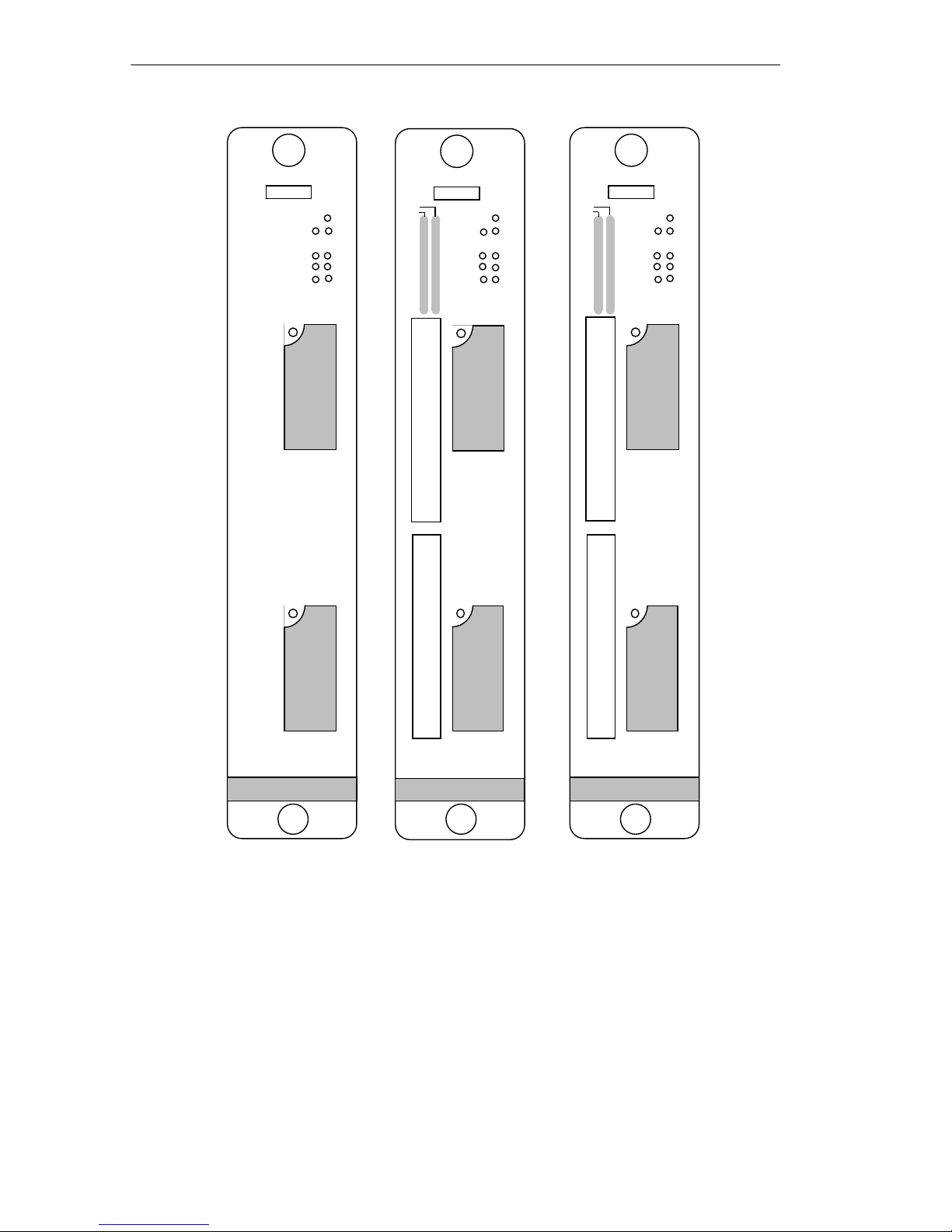
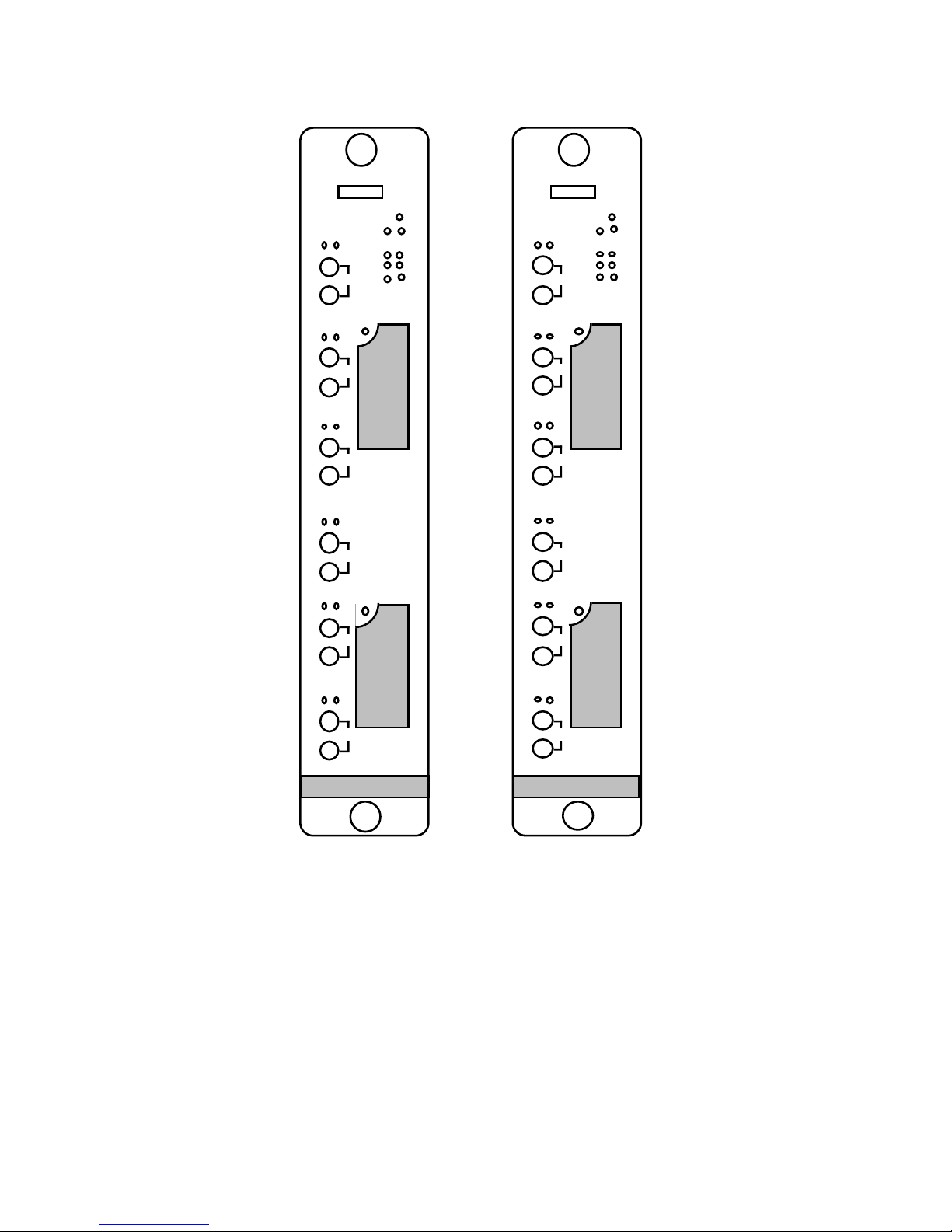
1.2.1 The TRRMIM -AT, TRRMIM-2AT and TRRMIM-4AT
The TRRMIM-AT, TRRMIM-2AT, and TRRMIM-4AT have two
front panel TPIMs for Ring-in and Ring-out connections
(see Figure 1-1). A variety of media types are supported.
Page 1-3
INTRODUCTION
TRRMIM-AT
RI
TRRMIM-2AT
LNK
ERR
16 MBMGMT
RO
CRS16
PEN
AWEN
R
I
T
P
I
M
R
O
T
P
I
M
PEN
1
2
3
4
5
6
7
8
9
10
11
12
1
X
2
X
3
X
4
X
5
X
6
X
7
X
8
X
9
X
10
X
11
X
12
X
RI RO
ERR
16 MBMGMT
CRS16
PEN
AWEN
R
I
T
P
I
M
R
O
T
P
I
M
TRRMIM-4AT
LNK
PEN
1
2
3
4
5
6
7
8
9
10
11
12
1
X
2
X
3
X
4
X
5
X
6
X
7
X
8
X
9
X
10
X
11
X
12
X
ERR
16 MBMGMT
RO
RI
CRS16
PEN
AWEN
R
I
T
P
I
M
R
O
T
P
I
M
Figure 1-1 The TRRMIM-AT, -2AT, and -4AT
The TRRMIM-2AT provides twelve active unshielded RJ-45
connectors supporting unshielded twisted pair (UTP) station (lobe)
cabling. These ports support voice grade unshielded twisted pair
(UTP) and IBM Type 3 UTP cable.
Page 1-4

INTRODUCTION
The TRRMIM-4AT provides twelve active shielded RJ-45 TCU
ports supporting Shielded twisted pair (STP) cabling. These ports
support IBM Type 1, 2, 6 and 9 shielded twisted pair cable.
1.2.2 The TRRMIM-F2T and TRRMIM-F3T
The TRRMIM-F2T, and TRRMIM-F3T have two front panel TPIMs
for Ring-in and Ring-out connections (see Figure 1-2). A variety of
media types are supported.
Both repeaters provide six fiber optic ports for station (lobe)
cabling. The TRRMIM-F2T supports multimode fiber optic cable
and the TRRMIM-F3T support single mode cable for the lobe
connections.
Page 1-5
INTRODUCTION
TRRMIM-F2T
FLNK
INS
TX
1
RX
FLNK
INS
TX
2
RX
FLNK
INS
TX
3
RX
FLNK
INS
TX
4
RX
FLNK
INS
TX
5
RX
FLNK
INS
TX
6
RX
RI RO
ERR
16 MBMGMT
CRS16
PEN
AWEN
TRRMIM-F3T
ERR
FLNK
INS
TX
1
RX
FLNK
R
I
T
P
I
M
TX
RX
TX
INS
2
FLNK
INS
3
RX
FLNK
INS
TX
4
RX
FLNK
INS
R
O
T
P
I
M
TX
RX
TX
5
FLNK
INS
6
RX
16 MBMGMT
RO
RI
CRS16
PEN
AWEN
R
I
T
P
I
M
R
O
T
P
I
M
Figure 1-2 The TRRMIM-F2T and TRRMIM-F3T
1.3 RING-IN RING-OUT CONNECTIONS
TPIMs are used for the Ring-in and Ring-out connections and
provide for many types of media. Table 1-1 lists the available
TPIMs.
Page 1-6

INTRODUCTION
Table 1-1 Available TPIMs
TPIM Media Type Connector
TPIM-T1 Shielded Twisted P air DB9
TPIM-T2 Unshielded Twisted P air RJ-45
TPIM-T4 Shielded Twisted P air RJ-45
TPIM-F2 Multi-mode Fiber Optic ST
TPIM-F3 Single mode Fiber Optic ST
1.4 RELATED MANUALS
The manuals listed below should be used to supplement the
procedures and other technical data provided in this manual. The
procedures in them will be referenced, where appropriate, but will
not be repeated.
Cabletron Systems
Multi Media Access Center Overview and Set
Up Guide
Cabletron Systems
Token Ring Local Management for the
Cabletron Systems TRMM
1.5 RECOMMENDED READING
The following publications are recommended if more information
is required on implementing a Token Ring network.
Local Area Networks, Token Ring Access Method
, IEEE Standard
802.5
Commercial Building Wiring Standard
No. 1907-B
(if approved, to be published as
, EIA Standard Proposal
EIA/TIA-568
)
Page 1-7

INTRODUCTION
LAN Troubleshooting Handbook
, Mark Miller (1989, M&T
Publishing, Inc.)
1.6 GETTING HELP
If you need additional support related to the Cabletron Systems
Token Ring products, or if you have any questions, comments or
suggestions related to this manual, please contact Cabletron
Systems Technical Support at:
Cabletron Systems, Inc.
P. O. Box 5005
Rochester, NH 03867-0505
Phone: (603) 332-9400
Page 1-8

REQUIREMENTS/SPECIFICATIONS
CHAPTER 2
INSTALLATION
REQUIREMENTS/SPECIFICATIONS
This chapter defines the requirements for other network elements
that will work with your token ring repeater and describes the
operational specifications for the TRRMIM-AT, TRRMIM-2AT
TRRMIM-4AT, TRRMIM-F2T, and TRRMIM-F3T. Before installing
your repeater, review the requirements and specifications that are
outlined in this chapter.
All conditions, guidelines, specifications, and requirements
included in this chapter must be satisfied to achieve optimum
performance from this equipment. Failure to follow these
guidelines may result in unsatisfactory network performance.
2.1 NETWORK REQUIREMENTS
Take care in planning and preparing the cabling and connections
for your network. The quality of the connections, the length of
cables and other conditions of the installation are critical factors in
determining the reliability of your network. The following are the
network requirements to operate this equipment.
2.1.1 Cable Specifications
Trunk Cabling
fiber, or multi-mode fiber, depending upon the TPIM used.
Lobe Cabling
specific repeater:
• The TRRMIM-2AT supports voice grade UTP cable, as
described in EIA Standard Proposal No. 1907-B, and IBM Type
3 (and category 4 and 5) UTP cabling on its twelve trunk
coupling unit (TCU) ports.
- The repeaters support UTP, STP, single-mode
- The media used for lobe cabling depends on your
Page 2-1

REQUIREMENTS/SPECIFICATIONS
• The TRRMIM-4AT supports IBM shielded twisted pair (STP)
cable Types 1, 2, 6, and 9 on its twelve trunk coupling unit
(TCU) ports.
• The TRRMIM-F2T supports multi-mode fiber optic cables using
ST connectors.
• The TRRMIM-F3T supports single-mode fiber optic cable using
ST style connectors.
STP CABLE TYPES
The TRRMIM-4AT, TPIM-T1 and TPIM-T4 support IBM Type 1, 2,
6, and 9 STP cabling as described in Table 2-1. STP cabling must
conform to the limits shown in Table 2-2.
Page 2-2

REQUIREMENTS/SPECIFICATIONS
Table 2-1 IBM Cable Types
Type 1 Two shielded twisted pairs (STP) of 22 AWG solid wire for
data. Used for the longest cable runs within the walls of
buildings.
Type 2 Similar to Type 1 data cable, but having four additional
unshielded twisted pairs of 22 AWG solid wire. These are
carried outside of the shield casing and are typically used
for voice communication. Frequently used to wire cable
runs within the walls of buildings.
Type 6 Two STP of 26 AWG stranded wire for data. This type is
used in patch panels or to connect devices to/from wall
jacks. Attenuation for Type 6 cable is 3/2 x Type 1 cable
(66 m of Type 6 = 100 meters of Type 1).
Type 9 Similar to Type 1, but uses 26 AWG solid wire. Attenuation
for Type 9 cable is 3/2 x Type 1 cable (66 m of Type 9 =
100 meters of Type 1).
Attenuation and Impedance
The maximum attenuation for specific STP cable types is shown in
Table 2-2. The attenuation values include the attenuation of the
cables, connectors, patch panels, and reflection losses due to
impedance mismatches in the segment.
Table 2-2 STP Cable Specifications
Frequency Impedance Attenuation
Types 1 & 2
4 Mhz
16 Mhz
Type 6 & 9
4 Mhz
16 Mhz
150Ω ±15%
150Ω ±15%
150Ω ±15%
150Ω ±15%
<22 dB/km (6.7 dB/1000 ft.)
<45 dB/km (13.7 dB/1000 ft)
<33 dB/km (10 dB/1000 ft.)
<66 dB/km (20 dB/1000 ft)
Page 2-3
 Loading...