

Page 1

TRMM-2
TOKEN RING
MANAGEMENT MODULE
USER’S GUIDE
Page 2

Page 3
TRMM-2 QUICK REFERENCE
QR.1 SWITCHBLOCK SW1 SETTINGS
JP2
Forced Network
Download
JP1
JP2
SW1
FNB Ring 4
NVRAM Clear
Station Port
(Interface 2)
FNB Ring 1
(Interface 1)
FNB Ring 2
SW1
unused
FNB Ring 3
Switchblock SW1 With Factory Default Settings
Switch Function
(Default settings shown in
bold
1 Ring speed of FNB Ring 1 for all port switching MIMs.
On – 16 Mbps
; Off – 4 Mbps
2 Ring speed of STATION port interface.
On – 16 Mbps
; Off – 4 Mbps
3 Ring speed of FNB Ring 2 for all port switching MIMs.
On – 16 Mbps
; Off – 4 Mbps
4 Toggle to clear NVRAM.
)
5 Unused
6 Unused
7 Ring speed of FNB Ring 3 for all port switching MIMs.
On – 16 Mbps
8 Ring speed of FNB Ring 4 for all port switching MIMs.
On – 16 Mbps
; Off – 4 Mbps
; Off – 4 Mbps
QR-1
Page 4

TRMM-2 QUICK REFERENCE
The TRMM-2 does not control the ring speeds of single-ring
NOTE
MIMs.
QR.2 LED STATUS DESCRIPTIONS
LED Status Meaning
OFF No power to module.
GREEN Testing and booting are nearly complete.
CPU
LWRP
16 Mb
XMT
RCV
Blinking
GREEN
RED Module is resetting or has detected errors.
Blinking RED Module has failed self-tests.
OFF The left connection is
AMBER
AMBER Interface ring speed is set to 16 Mbps.
OFF Interface ring speed is set to 4 Mbps
Flashing
GREEN
Blinking RED Beaconing condition on the ring.
OFF Interface is inactive.
RED Interface is disabled.
Flashing
AMBER
Operational.
not
left wrapped.
Left connection has been wrapped. FNB Ring 1
segment has been isolated from all other MIMs.
.
Information transmission by the TRMM-2
Network activity.
.
RED Interface disabled.
GREEN
NSRT
OFF Interface is not inserted into any ring.
QR-2
Interface is inserted into the ring and is participating
as a station on that ring.
Page 5

TRMM-2 QUICK REFERENCE
QR.3 CPU - CENTRAL PROCESSOR UNIT
The
CPU
LED indicates the operational status of the TRMM-2’s
CPU
processor. During start-up, the
operational states, as shown in the following table.
State(s) Meaning
OFF The module is not receiving power.
Briefly turns RED The module is resetting.
GREEN The module has passed its power check.
LED indicates a variety of
AMBER
Cycles through AMBER,
OFF, GREEN, and OFF for a
while.
Momentarily to RED, but
continues cycling.
If blinking RED,
(continuously)
GREEN Testing and booting are nearly complete.
Blinking GREEN
Performing diagnostic checks.
(It will stay here for a while.)
Testing and booting period has begun.
The module has detected errors during
the start-up sequence, but has continued
the process.
The module has failed self-tests.
The module is fully functional.
LED stays BLINKING GREEN under
normal operation.
The CPU
QR-3
Page 6

TRMM-2 QUICK REFERENCE
QR-4
Page 7

Only qualified personnel should perform installation
procedures.
NOTICE
Cabletron Systems reserves the right to make changes in specifications and other information
contained in this document without prior notice. The reader should in all cases consult Cabletron
Systems to determine whether any such changes have been made.
The hardware, firmware, or software described in this manual is subject to change without notice.
IN NO EVENT SHALL CABLETRON SYSTEMS BE LIABLE FOR ANY INCIDENTAL,
INDIRECT, SPECIAL, OR CONSEQUENTIAL DAMAGES WHATSOEVER (INCLUDING BUT
NOT LIMITED TO LOST PROFITS) ARISING OUT OF OR RELATED TO THIS MANUAL OR
THE INFORMATION CONTAINED IN IT, EVEN IF CABLETRON SYSTEMS HAS BEEN
ADVISED OF, KNOWN, OR SHOULD HAVE KNOWN, THE POSSIBILITY OF SUCH
DAMAGES.
Copyright 1997 by Cabletron Systems, Inc., P.O. Box 5005, Rochester, NH 03866-5005
All Rights Reserved
Printed in the United States of America
Order Number: 9031287-02 September 1997
Cabletron Systems, SPECTRUM, LANVIEW
Element Manager, MIM
VT100
is a trademark of Digital Equipment Corporation.
All other product names mentioned in this manual may be trademarks or registered trademarks of
their respective companies.
, and
TRMM-2
, FNB, and MMAC
are trademarks of Cabletron Systems, Inc.
are registered trademarks and
FCC NOTICE
This device complies with Part 15 of the FCC rules. Operation is subject to the following two
conditions: (1) this device may not cause harmful interference, and (2) this device must accept any
interference received, including interference that may cause undesired operation.
NOTE:
device, pursuant to Part 15 of the FCC rules. These limits are designed to provide reasonable
protection against harmful interference when the equipment is operated in a commercial environment.
This equipment uses, generates, and can radiate radio frequency energy and if not installed in
accordance with the operator’s manual, may cause harmful interference to radio communications.
Operation of this equipment in a residential area is likely to cause interference in which case the user
will be required to correct the interference at his own expense.
This equipment has been tested and found to comply with the limits for a Class A digital
WARNING:
party responsible for compliance could void the user’s authority to operate the equipment.
Changes or modifications made to this device which are not expressly approved by the
Printed on Recycled Paper
i
Page 8

NOTICE
DOC NOTICE
This digital apparatus does not exceed the Class A limits for radio noise emissions from digital
apparatus set out in the Radio Interference Regulations of the Canadian Department of
Communications.
Le présent appareil numérique n’émet pas de bruits radioélectriques dépassant les limites applicables
aux appareils numériques de la class A prescrites dans le Règlement sur le brouillage radioélectrique
édicté par le ministère des Communications du Canada.
VCCI NOTICE
This is a Class A product based on the standard of the Voluntary Control Council for Interference by
Information Technology Equipment (VCCI). If this equipment is used in a domestic environment,
radio disturbance may arise. When such trouble occurs, the user may be required to take corrective
actions.
CABLETRON SYSTEMS, INC. PROGRAM LICENSE AGREEMENT
IMPORTANT:
This document is an agreement between you, the end user, and Cabletron Systems, Inc. (“Cabletron”)
that sets forth your rights and obligations with respect to the Cabletron software program (the
“Program”) contained in this package. The Program may be contained in firmware, chips or other
media. BY UTILIZING THE ENCLOSED PRODUCT, YOU ARE AGREEING TO BECOME
BOUND BY THE TERMS OF THIS AGREEMENT, WHICH INCLUDES THE LICENSE AND
THE LIMITATION OF WARRANTY AND DISCLAIMER OF LIABILITY. IF YOU DO NOT
AGREE TO THE TERMS OF THIS AGREEMENT, PROMPTLY RETURN THE UNUSED
PRODUCT TO THE PLACE OF PURCHASE FOR A FULL REFUND.
Before utilizing this product, carefully read this License Agreement.
CABLETRON SOFTWARE PROGRAM LICENSE
1. LICENSE
package subject to the terms and conditions of this License Agreement.
You may not copy, reproduce or transmit any part of the Program except as permitted by the
Copyright Act of the United States or as authorized in writing by Cabletron.
2. OTHER RESTRICTIONS. You may not reverse engineer, decompile, or disassemble the
Program.
3. APPLICABLE LA W. This License Agreement shall be interpreted and governed under the laws
and in the state and federal courts of New Hampshire. You accept the personal jurisdiction and
venue of the New Hampshire courts.
. You have the right to use only the one (1) copy of the Program provided in this
ii
Page 9

NOTICE
EXCLUSION OF WARRANTY AND DISCLAIMER OF LIABILITY
1. EXCLUSION OF
writing, Cabletron makes no warranty, expressed or implied, concerning the Program (including
its documentation and media).
CABLETRON DISCLAIMS ALL WARRANTIES, OTHER THAN THOSE SUPPLIED TO
YOU BY CABLETRON IN WRITING, EITHER EXPRESSED OR IMPLIED, INCLUDING
BUT NOT LIMITED TO IMPLIED WARRANTIES OF MERCHANTABILITY AND
FITNESS FOR A PARTICULAR PURPOSE, WITH RESPECT TO THE PROGRAM, THE
ACCOMPANYING WRITTEN MA TERIALS, AND ANY A CCOMPANYING HARDWARE.
2. NO LIABILITY FOR CONSEQUENTIAL DAMAGES. IN NO EVENT SHALL
CABLETRON OR ITS SUPPLIERS BE LIABLE FOR ANY DAMAGES WHATSOEVER
(INCLUDING, WITHOUT LIMITATION, DAMAGES FOR LOSS OF BUSINESS,
PROFITS, BUSINESS INTERRUPTION, LOSS OF BUSINESS INFORMATION, SPECIAL,
INCIDENTAL, CONSEQUENTIAL, OR RELIANCE DAMAGES, OR OTHER LOSS)
ARISING OUT OF THE USE OR INABILITY TO USE THIS CABLETRON PRODUCT,
EVEN IF CABLETRON HAS BEEN ADVISED OF THE POSSIBILITY OF SUCH
DAMAGES. BECAUSE SOME STATES DO NOT ALLOW THE EXCLUSION OR
LIMITATION OF LIABILITY FOR CONSEQUENTIAL OR INCIDENTAL DAMAGES, OR
ON THE DURATION OR LIMITATION OF IMPLIED WARRANTIES, IN SOME
INSTANCES THE ABOVE LIMITATIONS AND EXCLUSIONS MAY NOT APPLY TO
YOU.
WARRANTY. Except as may be specifically provided by Cabletron in
UNITED STATES GOVERNMENT RESTRICTED RIGHTS
The enclosed product (a) was developed solely at private expense; (b) contains “restricted computer
software” submitted with restricted rights in accordance with Section 52227-19 (a) through (d) of the
Commercial Computer Software - Restricted Rights Clause and its successors, and (c) in all respects
is proprietary data belonging to Cabletron and/or its suppliers.
For Department of Defense units, the product is licensed with “Restricted Rights” as defined in the
DoD Supplement to the Federal Acquisition Regulations, Section 52.227-7013 (c) (1) (ii) and its
successors, and use, duplication, disclosure by the Government is subject to restrictions as set forth in
subparagraph (c) (1) (ii) of the Rights in Technical Data and Computer Software clause at
252.227-7013. Cabletron Systems, Inc., 35 Industrial Way, Rochester, New Hampshire 03867-0505.
iii
Page 10

NOTICE
DECLARATION OF CONFORMITY
Application of Council Directive(s):
Manufacturer’s Name:
Manufacturer’ s Address:
European Representative Name:
European Representative Address:
Conformance to Directive(s)/Product Standards:
Equipment Type/Environment:
89/336/EEC
73/23/EEC
Cabletron Systems, Inc.
35 Industrial Way
PO Box 5005
Rochester, NH 03867
Mr. J. Solari
Cabletron Systems Limited
Nexus House, Newbury Business Park
London Road, Newbury
Berkshire RG13 2PZ, England
EC Directive 89/336/EEC
EC Directive 73/23/EEC
EN 55022
EN 50082-1
EN 60950
Networking Equipment, for use in a
Commercial or Light
Environment.
Industrial
We the undersigned, hereby declare, under our sole responsibility, that the equipment packaged
with this notice conforms to the above directives.
Manufacturer Legal Representative in Europe
Mr. Ronald Fotino Mr. J. Solari
___________________________________ ___________________________________
Full Name Full Name
Principal Compliance Engineer Managing Director - E.M.E.A.
___________________________________ ___________________________________
Title Title
Rochester, NH, USA Newbury, Berkshire, England
___________________________________ ___________________________________
Location Location
iv
Page 11

CONTENTS
PREFACE
CHAPTER 1 INTRODUCTION
1.1 TRMM-2 Functional Overview.....................................................1-2
1.1.1 Port Assignment .............................................................1-2
1.1.2 Ring Poll Failure Recovery .............................................1-3
1.1.3 Network Management..................................................... 1-3
1.1.4 Dividing Stations Among Rings ......................................1-4
1.1.5 Segmenting The FNB For Additional Rings.................... 1-5
1.1.6 Module Bypassing, Ring Bypassing, And Port Disabling 1-6
1.1.7 STATION Port Interface.................................................. 1-7
1.1.8 Ring Speed Assignments ...............................................1-7
1.1.9 Automatic Configuration At Power-Up............................1-8
1.1.10 RMON Functionality........................................................1-8
1.1.11 SNMP Traps ...................................................................1-8
1.1.12 Ring Security ..................................................................1-8
1.1.13 Automatic Beacon Recovery Process (ABRP) ...............1-9
1.1.14 Access To MIB Libraries................................................. 1-9
1.1.15 TFTP Download Of Flash Image ....................................1-9
1.1.16 UPS Monitoring...............................................................1-9
1.2 User Access To Management Controls.....................................1-10
1.2.1 COM Ports....................................................................1-10
1.2.2 Telnet............................................................................ 1-11
1.2.3 Remote Network Management Applications................. 1-11
1.3 Front Panel Features.................................................................1-11
1.3.1 LANVIEW LEDs............................................................ 1-11
1.3.2 Reset Button.................................................................1-11
v
Page 12

CONTENTS
CHAPTER 2 INSTALLATION
2.1 Unpacking And Handling The TRMM-2 .......................................2-1
2.2 Setting Switches And Jumpers ....................................................2-2
2.2.1 Setting FNB Ring Speeds ...............................................2-2
2.2.2 Setting The STATION Port Interface Ring Speed...........2-4
2.2.3 Clearing NVRAM.............................................................2-4
2.2.4 Forced Network Download..............................................2-4
2.3 Management Module Overrides...................................................2-4
2.3.1 Single Ring MIMs............................................................2-4
2.3.2 Port Switching MIMs........................................................2-5
2.4 Installing The TRMM-2 Management Module..............................2-5
2.5 Resetting The Management Module............................................2-8
2.6 Attaching The STATION Port Interface........................................2-8
2.7 Configuring The TRMM-2 Using LM ..........................................2-10
2.7.1 Establishing The Terminal Connection..........................2-11
2.7.2 Assigning A Host IP Address ........................................2-12
2.7.3 Inputting The STATION Port Interface
Connection Location......................................................2-12
2.8 Choosing A Hub Configuration ..................................................2-13
2.8.1 Auto Configuration.........................................................2-14
2.8.2 Collapsed Backbone Configuration...............................2-14
2.8.3 Split Hub Configuration .................................................2-14
2.9 Connecting A UPS.....................................................................2-15
2.10 Power-On Diagnostics ...............................................................2-16
CHAPTER 3 MONITORING AND TROUBLESHOOTING
3.1 LANVIEW LEDs...........................................................................3-1
3.1.1 CPU - Central Processor Unit .........................................3-2
3.1.2 LWRP - Left Wrap...........................................................3-3
3.1.3 16 Mb - Ring Speed ........................................................3-3
3.1.4 XMT - Transmit................................................................3-4
3.1.5 RCV - Receive.................................................................3-4
3.1.6 NSRT - Insert ..................................................................3-4
3.2 Troubleshooting ...........................................................................3-5
3.2.1 Failure To Access Local Management............................3-5
3.2.2 No Response To Remote Management..........................3-5
3.2.3 Failure To Manage Rings................................................3-6
3.2.4 Checking The STATION Port Interface...........................3-7
3.2.5 Checking The Hub...........................................................3-7
3.2.6 Checking The Entire Network..........................................3-8
vi
Page 13

CONTENTS
APPENDIX A INTRODUCTION TO MULTIPLE-RING MMAC
FUNCTIONALITY
A.1 Why Use Multiple Rings? ............................................................A-1
A.2 The Flexible Network Bus (FNB).................................................A-1
A.2.1 New Terminology ............................................................A-1
A.3 Comparing Port Switching And Single Ring MIMs ......................A-2
A.3.1 Single Ring Versus Port Assignment Management
Modules...........................................................................A-4
A.3.2 Mixing Single Ring And Port Switching MIMs .................A-4
A.4 Available Rings............................................................................A-4
A.4.1 FNB Rings.......................................................................A-4
A.4.2 Auxiliary Rings ................................................................A-5
A.4.3 Bypassed Rings ..............................................................A-5
A.5 A Sample Configuration...............................................................A-6
APPENDIX B STATION PORT INTERFACE
B.1 Connections Within The Host MMAC..........................................B-1
B.1.1 Connections To Single Ring MIMs..................................B-2
B.1.2 Connections To Port Switching MIMs .............................B-3
B.2 Connections Outside The Host MMAC........................................B-4
B.3 Side-Band Management..............................................................B-5
APPENDIX C BEACONING PROTECTION AND RECOVERY
APPENDIX D SPECIFICATIONS AND SETUP REQUIREMENTS
D.1 TRMM-2 Specifications ...............................................................D-1
D.2 LM Terminal Setup Requirements...............................................D-1
D.3 Pinouts For Ports And Cables.....................................................D-3
D.3.1 STATION Port.................................................................D-3
D.3.2 COM Ports ......................................................................D-3
D.4 Environmental Requirements......................................................D-6
D.5 Regulatory Compliance...............................................................D-6
D.6 Year 2000 Compliance................................................................D-6
APPENDIX E SUPPORTED MIB GROUPS
INDEX
vii
Page 14

CONTENTS
viii
Page 15
PREFACE
Welcome to the
Guide
. This manual describes the TRMM-2 Management Module
TRMM-2 Token Ring Management Module User’s
capabilities and features, operating specifications and configuration,
installation, and troubleshooting procedures. Users of the TRMM-2
should have a basic working knowledge of the IEEE 802.5 standard for
Token Ring networks and Token Ring network physical components.
DOCUMENT CONVENTIONS
The following conventions are used throughout this document:
Bold Italics
other
publications.
NOTE
are used for references to Cabletron Systems documents and
Note
calls your attention to information of special importance.
TIP
!
CAUTION
Tip
gives you a helpful hint concerning procedures or actions.
Caution
avoid damaging software, configuration settings, or equipment.
Hazard
equipment damage or personal injury because of dangers
associated with electrical shock.
calls your attention to information you should heed to
calls your attention to an action that could result in
ix
Page 16

PREFACE
USING THIS MANUAL
Prior to installing and operating the TRMM-2, read through this manual
completely. If you are not familiar with port switching and four-ring
Flexible Network Bus (FNB) applications, read Appendix A.
The manual is organized as follows:
The Quick Reference Card at the front of this book provides visual aids
particularly useful to the installer.
Chapter 1,
Introduction
, describes the features and capabilities of the
TRMM-2.
Chapter 2,
Installation
, contains instructions for installing the TRMM-2
into a Multi Media Access Center (MMAC), attaching the STATION port
interface to a Token Ring, and configuring the TRMM-2 for operation.
Chapter 3,
Monitoring And T roubleshooting
, provides instructions for
using LANVIEW LEDs. It also describes procedures to be performed if
problems emerge after the installation of the TRMM-2.
Appendix A,
Introduction To Multiple-Ring MMAC Functionality
,
discusses the concepts of port switching, differences between switching
and single ring MIMs, and presents a sample configuration.
Appendix B,
STATION Port Interface
, describes the uses of the
STATION port interface.
Appendix C,
Beaconing Protection And Recovery
, describes Cabletron
Systems Automatic Beacon Recovery Process (ABRP).
Appendix D,
Specifications And Setup Requirements
specifications of the TRMM-2, the requirements for terminal equipment
attached to the TRMM-2, and details pinout specifications for ports and
cables.
Appendix E,
Supported MIB Groups
Bases and their respective functionality supported by the TRMM-2.
x
, lists the
, lists Management Information
Page 17

PREFACE
RELATED MANUALS AND RECOMMENDED READING
The Cabletron Systems manuals listed below should be used to
supplement procedures and other technical data provided in this manual.
TRMM-2 Local Management User’s Guide
Multi-Media Access Center Overview and Set Up Guide
The following publications are recommended as references about the
implementation of a Token Ring network:
Local Area Networks, Token Ring Access Method
, IEEE Standard
802.5
LAN Troubleshooting Handbook
, Mark Miller (1989, M&T
Publishing, Inc.)
Token Ring Technology Guide
, Cabletron Systems
The manuals referenced above can be obtained from the World W ide W eb
in Adobe Acrobat Portable Document Format (PDF) at the following site:
http://www.cabletron.com/manuals
These manuals are also available on the Cabletron Systems Hardware
Manuals CD-ROM.
GETTING HELP
If you need additional support related to this device, or if you have any
questions, comments, or suggestions concerning this manual, contact the
Cabletron Systems Global Call Center:
Phone (603) 332-9400
Internet mail support@ctron.com
FTP ctron.com (134.141.197.25)
Login
Password
BBS (603) 335-3358
Modem setting 8N1: 8 data bits, No parity, 1 stop bit
For additional information about Cabletron Systems or our products,
visit our World Wide Web site:
For technical support, select
anonymous
your email address
http://www.cabletron.com/
Service and Support
.
xi
Page 18

PREFACE
Before calling the Cabletron Systems Global Call Center, have the
following information ready:
•
Your Cabletron Systems service contract number
•
A description of the failure
•
A description of any action(s) already taken to resolve the problem
(e.g., changing mode switches, rebooting the unit, etc.)
•
The serial and revision numbers of all involved Cabletron Systems
products in the network
•
A description of your network environment (layout, cable type, etc.)
•
Network load and frame size at the time of trouble (if known)
•
The device history (i.e., have you returned the device before, is this a
recurring problem, etc.)
•
Any previous Return Material Authorization (RMA) numbers
xii
Page 19

CHAPTER 1
INTRODUCTION
The TRMM-2 Management Module (see Figure 1-1) can manage two
Token Rings simultaneously and control all Token Ring MIMs within a
Multi Media Access Center (MMAC). Also, it can assign ports to
different rings on port switching MIMs and provide error monitoring of
each ring on which it has an interface – one of which may be external to
the host MMAC. The TRMM-2 is 802.5 and IBM compliant.
TRMM-2
SN
RESET
R
S
I
T
A
N
G
T
1
I
O
N
Figure 1-1 TRMM-2 Management Module
C
O
M
1
C
O
M
2
TOKEN RING
1-1
Page 20

INTRODUCTION
1.1 TRMM-2 FUNCTIONAL OVERVIEW
The TRMM-2 offers the follo wing features for the monitoring and control
of Token Ring LANs:
• Complete compatibility with all Token Ring MIMs.
• Ability to assign ports to different rings on port switching MIMs.
• STATION port interface enables a cable connection to a dif ferent ring
so that the ring can be managed.
• Full RMON statistical/error network monitoring to track network
performance.
• Ability to act as a Distributed LAN Monitor (DLM) to reduce the
bandwidth needed for network management.
• Cabletron Systems Automatic Beacon Recovery Process (ABRP)
which enables networks to quickly recover from beaconing conditions
automatically .
• Ring Security options that allow you to regulate access to your
networks.
• SNMP compliance.
• Auto-configuration options (at initial power-on or after clearing
NVRAM) that allow you to automatically configure a collapsed
backbone or two independent Token Rings.
• A power-on Learn Mode that determines and maintains the
configuration of any port switching MIMs in the MMAC hub.
• Runtime IP address discovery that broadcasts BootP requests to obtain
an IP address if one is not assigned to Interface 1.
• Ring Poll Failure Recov ery that allo ws the TRMM-2 to automatically
remove stations that are causing ring poll failures.
1.1.1 Port Assignment
The TRMM-2 can individually assign ports to different rings on port
switching MIMs (e.g., TDRMIM and TRXMIM). This allows users to
insert into one of six different rings.
1-2
Page 21

INTRODUCTION
1.1.2 Ring Poll Failure Recovery
The Cabletron Systems Ring Poll Failure Recovery Process automatically
removes any station that fails to correctly participate in the ring poll
process. This feature ensures that other stations are not prevented from
inserting into the ring by an unresolved ring poll failure condition caused
by a malfunctioning station on the ring. Upon detecting the presence of
Neighbor Notification Incomplete (NNI) frames on the ring, the TRMM-2
learns the identity of the offending station and transmits a Remove MAC
frame to the station to remove it from the ring.
The TRMM-2 transmits a trap (if traps are enabled) to the Network
Management Station (NMS) notifying the NMS that it was either able or
not able to correct the ring poll failure condition. If the recovery process
corrects the ring poll failure condition, the trap notifies the NMS that the
condition was corrected and specifies the offending station’s MAC
address and the port on the hub to which the offending station was
connected.
If the offending station cannot be definitively removed from the ring by
the recovery process (that is, if the offending station repeatedly attempts
to re-insert before the recovery process has concluded), a trap notifies the
NMS that the condition was not corrected and also identifies the last
station to correctly participate in the ring poll process. This information
helps network-management personnel to pinpoint the offending station,
which may need to be physically disconnected from the lobe port to
resolve the problem.
1.1.3 Network Management
The TRMM-2 allows you to monitor, configure, and manage networks
using:
• Out-of-band Local Management (LM) application
• A variety of in-band SNMP network management softw are, including
the Cabletron Systems SPECTRUM family.
1-3
Page 22
INTRODUCTION
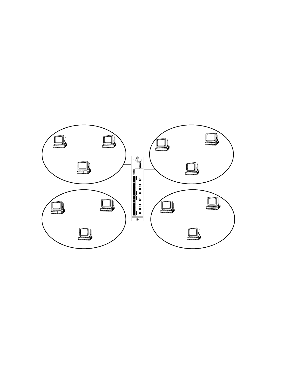
1.1.4 Dividing Stations Among Rings
The TRMM-2 is a port assigning management module. As described in
Appendix A, it provides the support needed by port switching MIMs to
execute port switching. This feature enables you to segment and manage
multiple Token Rings in the MMAC. Figure 1-2 shows an example of
how the TRMM-2 can assign the 12 ports of a TDRMIM to the FNB
rings.
In configuration A, Ports 1–3 are assigned to FNB Ring 1, Ports 4–6 are
assigned to FNB Ring 2, Ports 7–9 are assigned to FNB Ring 3, and Ports
10–12 are assigned to FNB Ring 4.
1
7
FNB Ring 1
3
FNB Ring 3
9
2
8
Configuration A
(Ports assigned
DR
SN
RING 1
16 Mb
16 Mb
RING 2
16 Mb
RING 3
16 Mb
RING 4
16 Mb
AUX 1
16 Mb
AUX 2
1
X
2
R
X
I
N
3
G
X
P
O
LINK PEN
4
R
X
T
S
5
X
1
6
X
7
X
8
R
X
I
N
G
9
X
P
O
10
LINK PEN
R
X
T
S
11
1
X
12
X
SWITCHING UTP/STP
TOKEN RING
BYP MGMT
LINK PEN
RI
RO
LINK PEN
RI
RO
10
FNB Ring 2
6
FNB Ring 4
22
ERR
IN USE
IN USE
IN USE
IN USE
IN USE
IN USE
TX
RX
TX
RX
TX
RX
TX
RX
4
12
5
11
to all FNB rings)
Figure 1-2 Sample Port/Station Assignments To The FNB Rings
(Configuration A)
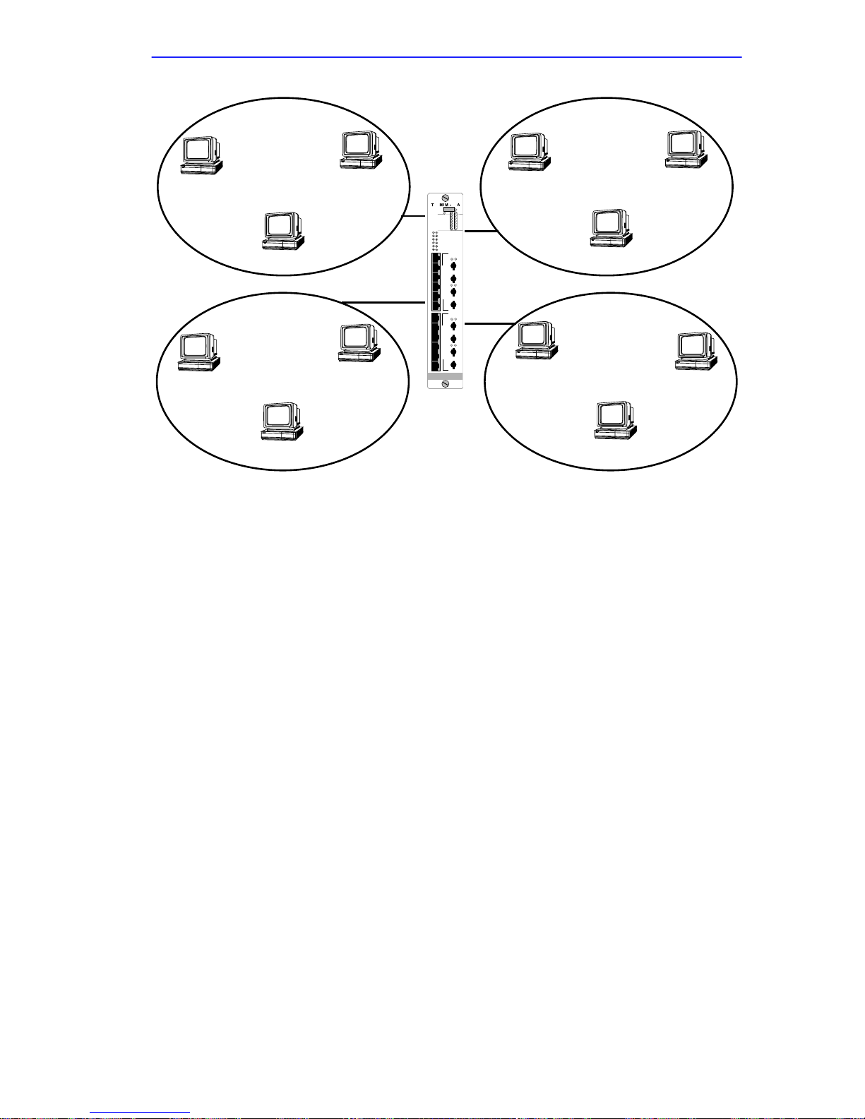
In Figure 1-3 (configuration B), Port 2 is assigned from FNB Ring 1 to
FNB Ring 3, and Port 9 is assigned from FNB Ring 3 to FNB Ring 1.
1-4
Page 23
INTRODUCTION
1
FNB Ring 1
3
7
FNB Ring 3
2
9
DR
SN
RING 1
RING 2
RING 3
RING 4
AUX 1
AUX 2
1
X
2
X
3
X
4
X
5
X
6
X
7
X
8
X
9
X
10
X
11
X
12
X
SWITCHING UTP/STP
8
TOKEN RING
Configuration B
(Port 2 assigned to
R
N
G
P
O
R
T
S
R
N
G
P
O
R
T
S
I
1
I
1
BYP MGMT
16 Mb
16 Mb
16 Mb
16 Mb
16 Mb
16 Mb
LINK PEN
RI
LINK PEN
RO
LINK PEN
RI
LINK PEN
RO
22
ERR
IN USE
IN USE
IN USE
IN USE
IN USE
IN USE
TX
RX
TX
RX
TX
RX
TX
RX
4
FNB Ring 2
6
10
FNB Ring 4
12
FNB Ring 3, Port 9
assigned to FNB Ring 1)
Figure 1-3 Sample Port/Station Assignments To The FNB Rings
(Configuration B)
5
11
Refer also to the TRMM-2 Local Management User’s Guide for details
on the execution of port assignment within an MMAC through the Local
Management application.
1.1.5 Segmenting The FNB For Additional Rings
FNB segmentation or “ring-wrapping” is another means of creating
additional Token Rings in the MMAC. In the MMAC each Token Ring
MIM connects to adjacent MIMs, forming continuous FNB rings
extending from the first Token Ring MIM to the last.
You can wrap the FNB interfaces of a single ring MIM
(e.g., TRMIM-24A) breaking the backplane and segmenting the FNB.
This is sometimes called ring wrapping. For example, the FNB shown in
Figure 1-4 has been segmented between the MMAC’s Slots 5 and 6. The
resulting segmented portions of the FNB remain fully functional, but the y
do not communicate with each other. Thus, you can increase the number
of Token Ring LANs operating in the MMAC by segmenting the FNB.
1-5
Page 24
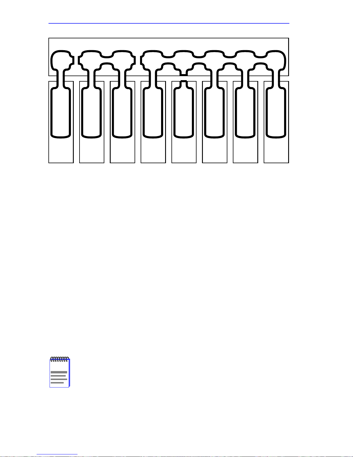
INTRODUCTION
FNB
Token Ring LAN
Board 8
Figure 1-4 Bird’s-Eye View Of FNB Segmentation And Bypassing
Token Ring LAN
Board 7
Token Ring LAN
Board 6
Token Ring LAN
Board 5
Token Ring LAN
Board 4
Token Ring LAN
Board 3
Token Ring LAN
Board 2
Token Ring LAN
<---|<---><---><-B->|---><---||---| |--->
Board 1
All single ring MIMs can wrap their connection (on either side) to the
FNB which makes it possible to segment the FNB; port switching MIMs
(e.g., TRXMIM) do not. See the TRMM-2 Local Management User’s
Guide for details and procedures.
1.1.6 Module Bypassing, Ring Bypassing, And Port
Disabling
This section describes the concepts and results of Module Bypassing,
Ring Bypassing, and Port Disabling.
Module Bypassing
The TRMM-2 allows you to create more isolated LANs by deliberately
bypassing a MIM’s ring connection from the FNB. For example, in the
configuration represented in Figure 1-4, the MIM in Slot 4 is bypassed
from the FNB.
Having a MIM in module bypass mode does not necessarily
NOTE
1-6
mean that the MIM is dev oid of network activity. Ev en if all rings
are bypassed from the backplane, the MIM may have active
LANs internally.
Page 25

INTRODUCTION
Ring Bypassing
With port switching MIMs (e.g., TRXMIM) bypassing may also be
performed on a per-ring basis. For e xample, a MIM’s Ring 3 channel may
be bypassed (i.e., isolated) from the FNB while the MIM’s Ring 1,
Ring 2, and Ring 4 rings remain connected to their respective FNB
channels. This is called a ring bypass. If all channels are bypassed from
the FNB, the module is effectively in full module bypass.
Port Disabling
You can disable any port on any MIM in the MMAC, thus preventing any
device from using that port.
1.1.7 STATION Port Interface
The STATION port interface can be used as the management interface to
any of the rings that are isolated from FNB Ring 1 within the host MMAC
simply by connecting the interface cable to a MIMs lobe port. Because
the STATION port interface cable is movable, it can also be used to
monitor operational conditions on Token Rings outside the host MMAC.
≈The STATION port interface can also:
• Serve as a data connection for in-band communications with the
TRMM-2 (e.g., Telnet, remote management communications, TFTP
downloads).
• Provide side-band management of the ring monitored by the FNB
interface.
See Section 2.6, for details on connecting a lobe cable to the STATION
port interface. See Appendix B for operational information on the
STATION port interface.
1.1.8 Ring Speed Assignments
The TRMM-2 assigns FNB ring speed settings (4 Mbps or 16 Mbps).
This sets the interface between MIMs and FNB rings. See Section 2.2 for
details about the interaction of MIMs and the TRMM-2. The TRMM-2
can also set the speed of auxiliary rings through the Management
Information Base (MIB).
1-7
Page 26

INTRODUCTION
1.1.9 Automatic Configuration At Power-Up
The TRMM-2 stores operational parameters in its Non-Volatile RAM
(NVRAM). Whenever the TRMM-2 is powered-up or reset, it compares
the MIMs currently in the hub with those last registered. All MIMs
recognized throughout the hub are placed in management mode and
reconfigured according to settings stored in the NVRAM. Thus,
configuration settings stored before power-down are reinstated at the next
power-up.
Any MIM that is not recognized at power-up is allowed to operate in the
configuration dictated by its own hardware settings. The TRMM-2
observes the MIM’s configuration and stores them in NVRAM.
1.1.10 RMON Functionality
The TRMM-2 performs RMON (Remote Monitoring MIB) statistical
monitoring on all interfaced LANs. See Appendix E, for a listing of
supported MIBs. Using the STATION port interface to make the
connection, the TRMM-2 can perform RMON monitoring on any Token
Ring network within a cable’s reach.
1.1.11 SNMP Traps
The TRMM-2 operates as a Ring Error Monitor (REM), collecting data
on the network, monitoring performance conditions, and noting station
access to the Token Rings. Using the Local Management application, you
may configure the TRMM-2 to issue SNMP traps to selected network
management stations to provide information about the network.
1.1.12 Ring Security
Ring Security is a feature that enables network managers to monitor and
restrict station access to Token Rings through an editable “allowed list”
which registers the MAC address of each station “allowed” on the ring.
See the TRMM-2 Local Management User’s Guide for details and
procedures.
1-8
Page 27

INTRODUCTION
1.1.13 Automatic Beacon Recovery Process (ABRP)
The TRMM-2’s Automatic Beacon Recovery Process (ABRP) actively
guards against network interruptions due to beaconing. When beaconing
is detected, ABRP isolates the problematic portion of the network from
the ring, enabling the network to recover without user intervention and
preventing beaconing conditions from halting network operations. See
Appendix C, for more information on ABRP and the netw ork problems it
addresses.
1.1.14 Access To MIB Libraries
Among the tools provided by the TRMM-2 Local Management is a MIB
Navigator. This tool allows you to browse through and access the library
of Management Information Bases (MIBs) available with the TRMM-2.
A list of supported MIBs is provided in Appendix E. See the TRMM-2
Local Management User’s Guide for further information on the use of
the MIB Navigator tool.
1.1.15 TFTP Download Of Flash Image
The firmware in the TRMM-2, sometimes referred to as the flash image,
is the module’ s operating system file. Using the Local Management Flash
Download screen, this file may be replaced or upgraded; a new image
may be downloaded by TFTP (Trivial File Transfer Protocol) from a
TFTP server into the on-board memory of the TRMM-2. Either of the
TRMM-2’s interfaces (FNB or STATION) may carry the transfer.
1.1.16 UPS Monitoring
The TRMM-2 can monitor an Uninterruptible Power Supply (UPS). The
devices are connected via a special cable from the TRMM-2 COM port to
the UPS. See the TRMM-2 Local Management User’s Guide for details
about configuring the COM ports to support UPS monitoring.
1-9
Page 28

INTRODUCTION
1.2 USER ACCESS TO MANAGEMENT CONTROLS
The TRMM-2 supports multiple simultaneous communications sessions.
By connecting to properly configured COM ports, you can gain
out-of-band access to management controls using any machine configured
to emulate a Digital Equipment Corporation VT100 series terminal.
The TRMM-2 also supports in-band Telnet access to local management
through the FNB and STATION port interfaces. This provides remote
in-band access to the Local Management application and allows you to
exercise management control through a v ariety of in-band remote network
management software packages including Cabletron Systems
SPECTRUM family.
The TRMM-2 Local Management User’s Guide provides all necessary
procedures for accessing the Local Management application.
1.2.1 COM Ports
There are two RJ45 connector COM (Communications) ports on the front
panel that provide local out-of-band EIA RS232C connections to the
TRMM-2. Using Local Management, you may select from two COM port
applications: LM, or UPS. Also, both COM ports can support a modem
connection.
LM
When configured for LM (default configuration), COM ports provide
access directly to the Local Management application for any actual or
emulated DEC VT100 terminal configured according to Appendix D.
Each COM port automatically detects the baud rate of the connecting
terminal and self-configures accordingly, when the user sends a keyboard
character.
Although either port will support the Local Management
NOTE
connection, start-up diagnostic information regarding BOOTP
and network interface initialization is available only on COM 2.
1-10
Page 29

INTRODUCTION
UPS
The UPS COM port configuration supports a monitoring connection for
an Uninterruptible Power Supply (UPS). After using a DB9-to-RJ45 cable
to connect the UPS and the TRMM-2, a MIB tool can be used to get
specific information about the state of the UPS.
1.2.2 Telnet
Once the TRMM-2 is given an IP address, as described in Section 2.7.2,
you can access the Local Management application directly via a Telnet
session from either interfaced network.
1.2.3 Remote Network Management Applications
All Cabletron Systems Token Ring management modules are SNMP
compliant. Thus, you may communicate with the TRMM-2 through any
remote SNMP network management software package, including
Cabletron Systems SPECTRUM family. The TRMM-2 serves as the
in-band SNMP management agent for both interfaced networks.
1.3 FRONT PANEL FEATURES
The front panel of the TRMM-2 has a LANVIEW LED system and a reset
button.
1.3.1 LANVIEW LEDs
The LANVIEW LED system comprises several LEDs, located on the
front panel of the TRMM-2. Operating as a visual diagnostic and status
monitoring system, the LEDs light, blink, and flash in different colors to
indicate various network and module-specific conditions, thereby
facilitating the quick diagnosis of physical layer network problems. The
system is discussed in detail in Section 3.1.
1.3.2 Reset Button
The Reset button causes the module to reboot when pressed. See
Section 2.5, for a detailed description of the Reset procedure.
1-11
Page 30

INTRODUCTION
1-12
Page 31

CHAPTER 2
INSTALLATION
This chapter discusses the following topics:
• Unpacking the TRMM-2
• Setting switches on the TRMM-2
• Management module overrides
• Installing the TRMM-2 into an MMAC
• Resetting the TRMM-2
• Attaching the STATION port interface
• Configuring the TRMM-2 using the Local Management application
• Choosing a hub configuration
• Connecting a UPS so it can be monitored by the TRMM-2
2.1 UNPACKING AND HANDLING THE TRMM-2
Electrostatic Discharge (ESD) can damage the TRMM-2. To
!
CAUTION
To unpack the TRMM-2:
1. Carefully remove the module and other items from the shipping box.
You should have the following items:
• TRMM-2 module
prevent ESD damage when handling the module:
• Wear the grounding wrist strap.
• Hold only the edges of the board or the metal front panel.
• Avoid touching the components or the surface of the board
.
• Disposable grounding wrist strap
2-1
Page 32

INSTALLATION
• RS232 console cable kit, which includes an RJ45-to-DB9 PC
adaptor and a straight-through cable with RJ45 plugs
• TRMM-2 Management Module User’s Guide and TRMM-2
Quick Installation Guide
Save the box and packaging materials for possible future repackaging
and shipment.
2. Put on the grounding wrist strap. Remove the TRMM-2 from the
protective bag and place it on top of the bag in a dry, static-free,
dust-free area.
3. Inspect the contents for any signs of damage.
Notify Cabletron Systems Global Call Center (see Preface) if you
detect any damaged or missing parts.
2.2 SETTING SWITCHES AND JUMPERS
See Figure 2-1 when setting switches. Only reposition the
NOTE
documented jumpers and switches. All other jumpers are set at
the factory. Note their positions for future reference.
Switchblock 1 (SW1), shown in Figure 2-1, contains switches that:
• Set the speed of FNB rings
• Set the STATION port interface ring speed
• Clear NVRAM
2.2.1 Setting FNB Ring Speeds
Switches 1, 3, 7, and 8 set the ring speeds for the FNB Rings (Table 2-1).
These settings may override hardware speed settings on port switching
MIMs. (See Section 2.3 for complete details about management module
overrides.) The switches do not override the ring speed setting for single
ring MIMs.
2-2
Page 33

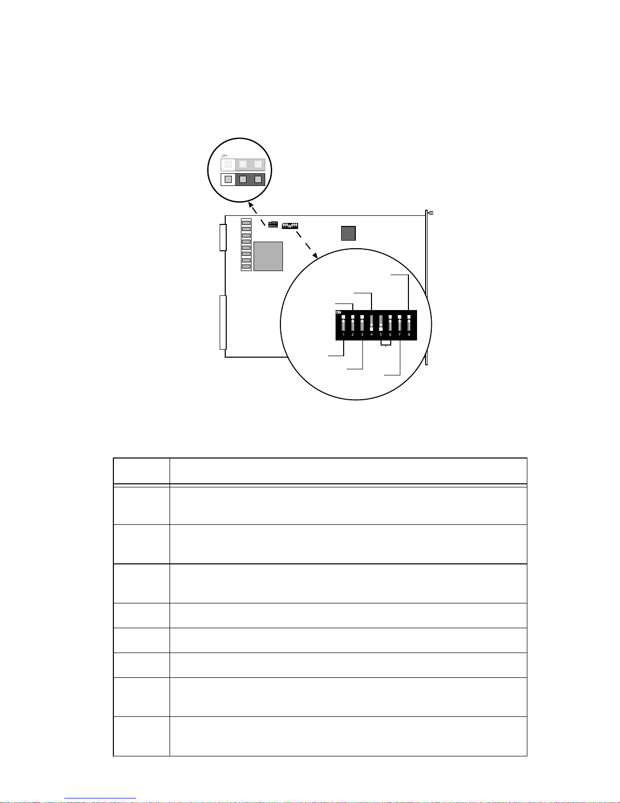
JP2
Forced Network
Download
INSTALLATION
JP1
JP2
SW1
FNB Ring 4
NVRAM Clear
Station Port
(Interface 2)
Switchblock 1
Figure 2-1 Management Module Switches And Jumpers
FNB Ring
Ring 1 1
Ring 2 3
Ring 3 7
SW1
FNB Ring 1
(Interface 1)
FNB Ring 2
FNB Ring 3
unused
Table 2-1 Setting FNB Ring Speeds
Switch
Number
Switch Position/Ring Speed
On – 16 Mbps
Off – 4 Mbps
On – 16 Mbps
Off – 4 Mbps
On – 16 Mbps
Off – 4 Mbps
Ring 4 8
On – 16 Mbps
Off – 4 Mbps
Note: Default settings in bold.
2-3
Page 34

INSTALLATION
2.2.2 Setting The STATION Port Interface Ring Speed
Switch 2 sets the ring speed of the STATION port interface
(see Table 2-2). The STATION port interface must be set to the same
speed as the ring that it will manage.
Table 2-2 Setting STATION Port Interface Ring Speed
Switch 2 Position
On 16 Mbps (Default setting)
Off 4 Mbps
STATION Port Interface
Ring Speed
2.2.3 Clearing NVRAM
Switch 4 clears NVRAM. The hub’s configuration is stored in the
NVRAM of the management module. To clear NVRAM and erase the
configuration of the hub (except for the System Time and System Date),
move Switch 4 to the opposite position. This a toggle switch, therefore
ON/OFF are irrelevant.
2.2.4 Forced Network Download
The JP2 jumper is used to force the TRMM-2 to initiate a BootP server
forced network download. Any repositioning of JP2 will cause the
TRMM-2 to initiate a network download. If no BootP serv er responds, the
TRMM-2 will continue to send BootP requests until it is reset. Upon
reset, it will send BootP requests (less than eleven times). If no BootP
server responds, the TRMM-2 will resume normal operation booting from
the Flash memory instead. (Consult Figure 2-1 for the location of the JP2
jumper.)
2.3 MANAGEMENT MODULE OVERRIDES
The TRMM-2 treats the configuration setting of single ring MIMs
differently than port switching MIMs.
2.3.1 Single Ring MIMs
The TRMM-2 will not override single ring MIMs. The TRMM-2 will
read the configuration jumpers/switches on single ring MIMs and
implement those settings.
2-4
Page 35

INSTALLATION
2.3.2 Port Switching MIMs
Although port switching MIMs have switches and jumpers to set their
configuration, the TRMM-2 Management Module controls the speed of
the FNB rings and the assignment of ports to different rings. This may
cause conflicts that result in the overriding of a MIM’s configuration or
bypassing a MIM ring from the FNB.
At boot-up a non-configured TRMM-2 detects the slot and configuration
of each Token Ring MIM in the hub. It remembers this information by
saving it to NVRAM. Thus, once a management module stores the
configuration of a port switching MIM:
• Any subsequent changes to the MIM’s switches and jumpers will be
overridden.
• MIM rings set to a different speed than FNB rings (at power-on) are
bypassed from the FNB.
Any later attempt to use the switches and jumper of a MIM to set its
configuration will be overridden until the management module’s
NVRAM is cleared or a different type of MIM is installed.
2.4 INSTALLING THE TRMM-2 MANAGEMENT MODULE
Only qualified personnel should perform installation
procedures.
The following guidelines are helpful in configuring the system at
installation:
• The TRMM-2 must be installed into Slot 1 of an MMAC. This is the
right-most slot in the MMAC-M8FNB and MMAC-M5FNB, or the
lowest slot in the MMAC-M3FNB (see Figure 2-2).
• Ensure that the MMAC has the proper type and number of power
supplies to support the configuration. Call the Cabletron Systems
Global Call Center to determine the exact power requirement for your
configuration.
2-5
Page 36

INSTALLATION
Slot For TRMM-2
MIM Slots MIM Slots
Slot For TRMM-2
MIM Slots
MMAC-M3FNB/-3FNB
Figure 2-2 Slot Location For TRMM-2 In An MMAC
Slot For TRMM-2
MMAC-M8FNB/-8FNBMMAC-M5FNB/-5FNB
Multiple Token Ring MIMs, within an MMAC, are automatically linked
at power on, provided that the MMAC has a Flexible Network Bus
(FNB). Without an FNB, the individual MIMs will not be linked, but
rather will form independent Token Ring networks.
It is recommended that you perform the initial installation with
TIP
the MMAC not powered on.
Put on the anti-static wrist strap included in the shipment and install the
TRMM-2 into the MMAC as follows:
1. Remove the blank protective panel from the Slot 1 (see Figure 2-3).
2. Slide the TRMM-2 into the MMAC chassis (see Figure 2-4). Be sure
that the module is in the slot guides at the top and bottom of the
chassis.
When performed correctly, you should be able to feel the management
and FNB interface connectors on the TRMM-2 insert smoothly and
snugly into their respective connectors on the MMAC backplane. The
front panel of the TRMM-2 should align with the front panels of other
installed modules.
Never use more than the minimal amount of physical force
!
CAUTION
necessary to insert the TRMM-2 into the MMA C. If you feel any
resistance while inserting, STOP! Remove the module and
inspect the slot and the TRMM-2 for obstructions or structural
irregularities. If you detect damaged components, call
Cabletron Systems Global Call Center for assistance.
2-6
Page 37

INSTALLATION
Figure 2-3 Removing The Protective Panel Of Slot #1
TRMM-2
SN
RESET
R
S
I
T
A
N
G
T
1
I
O
N
C
O
M
1
C
O
M
2
TOKEN RING
Figure 2-4 Inserting The TRMM-2 Into The MMAC
3. Secure the TRMM-2 to the MMAC by tightening the knobs on the
TRMM-2.
Failure to tighten down the knobs may result in a faulty connection to
the MMAC backplane.
TRMM-2 LEDs light in accordance with the existing configuration.
2-7
Page 38

INSTALLATION
2.5 RESETTING THE MANAGEMENT MODULE
The TRMM-2 has a Reset button that is accessible through a small hole in
its front panel (see Figure 2-5). Pressing Reset causes the module to
simulate a power OFF/ON cycle. Resetting the TRMM-2 will not effect
the operation of other MIMs in the hub.
To reset the TRMM-2, press the Reset button with a non-conductive,
pointed instrument that can be inserted through the access hole. When the
button is released, the module begins its boot sequence and self-tests.
Upon successful completion of the boot-up procedure, the CPU LED
should return to blinking GREEN. If the CPU LED fails to return to
blinking GREEN at the end of the boot/self-test sequence, note which
LEDs are lit and consult Section 3.1.
TRMM-2
SN
RESET
Reset button
R
S
I
T
A
N
G
T
1
I
O
N
Figure 2-5 Reset Button On Front Panel
2.6 ATTACHING THE STATION PORT INTERFACE
If you want the TRMM-2 to manage another ring (either internal or
external to the host MMAC), the STATION port interface must be
attached to that ring. It can attach to any ring except the one being
managed by the FNB management interface. See Appendix B, for
information on valid and invalid connections. See Appendix D, for
STATION port pinouts.
2-8
Page 39

INSTALLATION
To connect the STATION port interface to a ring:
1. Select a LAN (other than FNB Ring 1) to be monitored by the
TRMM-2 and note its ring speed.
The example in Figure 2-6 shows a connection to a ring internal to the
host MMAC using a TRXMIM with port switching access to FNB
Rings 2, 3, or 4.
2. Ensure that the ring speed of the STATION port interface matches the
ring speed of its destination Token Ring.
This may require removing the TRMM-2 from the MMAC and setting
Switch 2 on the switchblock SW1 (see Section 2.2).
MMAC - M8FNB
24
24
SN
SN
ERR
BYP MGMT
ERR
BYP MGMT
16 Mb
ACT
RING 1
16 Mb
ACT
RING 1
16 Mb
RING 2
ACT
16 Mb
RING 2
ACT
16 Mb
RING 3
ACT
16 Mb
RING 3
ACT
RING 4
16 Mb
ACT
RING 4
16 Mb
ACT
16 Mb
AUX 1
ACT
16 Mb
AUX 1
ACT
16 Mb
AUX 2
ACT
16 Mb
AUX 2
ACT
1
1
13
13
X
X
X
X
14
X
15
X
16
X
17
X
18
X
19
X
20
X
21
X
22
X
23
X
24
X
SWITCHING UTP/STP
TOKEN RING
2
X
3
X
4
X
5
X
6
X
7
X
8
X
9
X
10
X
11
X
12
X
14
X
15
X
16
X
17
X
18
X
19
X
20
X
21
X
22
X
23
X
24
X
SWITCHING UTP/STP
TOKEN RING
2
X
3
X
4
X
5
X
6
X
7
X
8
X
9
X
10
X
11
X
12
X
STATION
Connector
Cable
15
X
16
X
17
X
18
X
19
X
TRXMIM-24A Lobe Port
RJ45 Connector
3
X
4
X
5
X
6
X
7
X
TRMM-2 STATION Port
DB9 Connector
Figure 2-6 STATION Cable Attachment To TRXMIM Port
RJ45 To
DB9 Adaptor
2-9
Page 40

INSTALLATION
3. Attach the lobe cable to the STATION port DB9 connector on the
TRMM-2 faceplate. When connecting with UTP cable, use a TRMF-2
media filter (as shown in Figure 2-7).
4. Attach the other end of the cable to the selected Token Ring LAN
using any concentrator lobe port assigned to the destination ring
(for example, a TRXMIM lobe port that is assigned to
FNB Ring 2).
TRMM-2
SN
RESET
R
S
I
T
A
N
G
T
1
I
O
N
TRMF-2
802.5 MEDIA FILTER
C
O
M
1
C
O
M
2
TOKEN RING
Figure 2-7 Attaching A Cable To The STATION Port Interface Using A
TRMF-2 Media Filter
The length of the STATION port interface cable is limited b y the
NOTE
device to which it is attached. Consult the documentation for
that device for information about lobe lengths.
2.7 CONFIGURING THE TRMM-2 USING LM
This section provides a quick reference for LM configurations to
complete the installation. Detailed instructions are provided in the
TRMM-2 Local Management User’s Guide.
2-10
Page 41

INSTALLATION
2.7.1 Establishing The Terminal Connection
Both COM ports are factory-configured to support RS232 connections to
actual or emulated VT100 series terminals. To establish the terminal
connection:
1. Attach the supplied terminal cable to a COM port configured for Local
Management (see Figure 2-8).
2. Attach the appropriate adapters (9 or 25 pin) to the other end of the
cable and insert it into the RS232 port on the LM terminal.
3. Ensure the TRMM-2 is powered-up. If using an emulator for the Local
Management terminal, run the emulation program.
4. Press the Enter (or Return) key on the terminal to enable the COM
port to automatically detect the baud rate. The Local Management
password screen appears.
5. Press the Enter (or Return) key to enter the Main Menu screen.
(The default password is no entry. If the TRMM-2 has been configured
before, a password may be required.)
6. To disconnect from Local Management, disconnect the cable (or quit
the emulator program).
MMAC -M8FNB
SN
SN
ERR
BYP MGMT
ERR
BYP MGMT
16 Mb
ACT
16 Mb
ACT
RING 1
RING 1
16 Mb
RING 2
16 Mb
RING 2
ACT
ACT
16 Mb
RING 3
16 Mb
RING 3
ACT
ACT
RING 4
RING 4
16 Mb
16 Mb
ACT
ACT
16 Mb
AUX 1
16 Mb
AUX 1
ACT
ACT
16 Mb
AUX 2
16 Mb
AUX 2
ACT
ACT
1
1
2
2
X
X
X
X
3
3
4
4
X
X
X
X
5
5
6
6
X
X
X
X
7
7
8
8
X
X
X
X
9
9
10
10
X
X
X
X
11
11
12
12
X
X
X
X
13
13
14
14
X
X
X
X
15
15
16
16
X
X
X
X
17
17
18
18
X
X
X
X
19
19
20
20
X
X
X
X
21
21
22
22
X
X
X
X
23
23
24
24
X
X
X
X
SWITCHING UTP/STP
SWITCHING UTP/STP
TOKEN RING
TOKEN RING
C
O
M
1
C
O
M
2
TOKEN RING
Local Management
Console
Figure 2-8 Connecting The T erminal Cable T o The TRMM-2
Local
Management
Cable
2-11
Page 42

INSTALLATION
2.7.2 Assigning A Host IP Address
You must assign an IP address to the SNMP Agent (management agent) in
the TRMM-2 if you want to manage the module remotely. Assign an IP
address as follows:
1. Consult the Network Administrator for an IP address.
2. Enter the Main Menu screen as described in Section 2.7.1.
3. Select the SETUP MENU screen.
4. Enter the SYSTEM LEVEL screen.
5. Select the Host IP address field and type the appropriate IP
address. Press the Enter key to accept the entry.
6. Select SAVE at the bottom of the screen and press the Enter key.
The TRMM-2 does a warm reboot that does not effect network traffic.
2.7.3 Inputting The STATION Port Interface
Connection Location
Whenever the STATION port interface cable connection is
NOTE
To execute physical control (such as ring security and beacon recovery)
over a second Token Ring, you must install the STATION port interface
connection according to the guidelines defined in Appendix B, and
provide a physical location (slot and port number) of the STATION port
interface connection.
1. Enter the System Level screen as described in Section 2.7.2.
installed or moved, the f ollo wing procedure must be perf ormed.
See Section 2.6 for STATION port interface cable connection
instructions.
2. Select the STN Assignment toggle fields.
3. Toggle through the values in each STN Assignment field to set the slot
and port numbers (to identify the location of the STATION port
interface connection). Press the Enter key to accept the values.
2-12
Page 43

INSTALLATION
The default value of the STN Assignment is Slot 0, Port 0. This
NOTE
indicates either a location that is outside the host MMAC or that
the STATION port interface is not in use.
4. Select SAVE at the bottom of the screen and press the Enter key to
complete the configuration.
2.8 CHOOSING A HUB CONFIGURATION
When you install a new TRMM-2 (or clear NVRAM on one that is
configured), the Configuration screen appears during power-on
(see Figure 2-9).
This screen allows you to configure the hub as one of the following:
• Hub, based on the settings of the MIMs’ switches and/or jumpers
(Default condition)
• Collapsed Backbone
• Split Hub
The Configuration screen appears for 60 seconds. In order to
NOTE
“freeze” the screen so you can make selections, press the
Spacebar on the keyboard.
USER ALERT! No MMAC hub/MIM configuration information is saved in this
management module.
MULTI-RING MIMs:
--------------- The management module will query each Multi-Ring MIM for port configuration,
with the following options:
COLLAPSED BACKBONE - Each MIM contains isolated rings.
DEFAULT - Management module will unbypass each MIM.
SINGLE-RING MIMs:
---------------- The management module will always set port configuration defaults, with
the following options:
SPLIT HUB - The hub will be segmented into two rings starting at
a user specified slot.
COLLAPSED BACKBONE - Each MIM contains an isolated ring.
DEFAULT - Management module will connect all MIMs together to
create one ring with all ports enabled.
*******************************************************************************
Configure as a SPLIT HUB or COLLAPSED BACKBONE? y/[n]: (Secs. Remaining:54)
Figure 2-9 Configuration Screen
2-13
Page 44

INSTALLATION
2.8.1 Auto Configuration
The Auto Configuration option is the default condition. It is implemented
automatically when you install a new TRMM-2 or clear NVRAM on one
that is configured. (See Section 2.2.3 for details about clearing NVRAM.)
Auto Configuration will apply the MIMs’ switches and/or jumper(s)
settings. To implement this option press the Enter key or wait 60 seconds.
2.8.2 Collapsed Backbone Configuration
The Collapsed Backbone configuration isolates all MIM rings from the
FNB. An external device such as a switch or router is required for these
rings to communicate. To implement a Collapsed Backbone:
1. Install a new TRMM-2 or clear NVRAM on one that is configured
and install it.
The “Configure as SPLIT HUB or COLLAPSED BACKBONE?
y/[n]” message appears.
2. Press Y.
The “Configure a SPLIT HUB allowing two Token Rings
to exist? y/[n]” message appears.
3. Press N.
The “
Configure as COLLAPSED BACKBONE Hub? y/[n]”
message appears.
4. Press Y.
The “
All MIMs will bypass the FNB rings.
Is this correct? y/[n]” message appears.
5. Press Y.
Hub Reconfiguration selected:
The “
Configuring as Collapsed Backbone” message appears.
2.8.3 Split Hub Configuration
The Split Hub configuration allows you to segment the FNB into two
Token Rings adjacent to any single ring MIM in the hub. You cannot
segment the hub between any port switching MIMs.
2-14
Page 45

INSTALLATION
To implement a Split Hub configuration:
1. Install a new TRMM-2 or clear NVRAM on one that is configured
and install it.
The “Configure as SPLIT HUB or COLLAPSED BACKBONE?
y/[n]” message appears.
2. Press Y.
The “Configure a SPLIT HUB allowing two Token Rings
to exist? y/[n]” message appears.
3. Press Y.
The “
Enter slot number which begins second ring? 2-8”
message appears.
4. Enter the slot number. (The second ring will begin at that slot.)
If you enter a slot that contains a port switching MIM, the “
character [x]” message appears. Re-enter a correct slot.
The “
5. Press Y.
The “
Is this correct? y/[n]” message appears.
Configuring as Split Hub” message appears.
INVALID
2.9 CONNECTING A UPS
The TRMM-2 can be used to monitor a UPS. It must be connected to the
UPS using a special DB9-to-RJ45 cable assembly available from
Cabletron Sales. See Table D-5 for details about pinouts for the cable.
2-15
Page 46

INSTALLATION
2.10 POWER-ON DIAGNOSTICS
During the start-up sequence, the TRMM-2 performs diagnostic hardware
testing. The progress of this testing can be monitored by connecting an
LM terminal to the COM2 Port. Some examples of the tests performed by
the TRMM-2 are:
• Memory tests
• SCC console tests
• Timer tests
• Token Ring adapter tests
2-16
Page 47

CHAPTER 3
MONITORING AND TROUBLESHOOTING
This chapter describes how to verify proper configuration and operation
of the TRMM-2 using the LANVIEW LED system. It also provides a
checklist to help isolate problems typically encountered during
installation.
3.1 LANVIEW LEDS
LANVIEW LEDs are a built-in visual diagnostic system of colored LEDs
which are used for monitoring module and network status. Figure 3-1
shows the location of the LEDs. Table 3-1 lists the LEDs and their
function.
NOTE
TRMM-2
SN
RESET
R
S
I
T
A
N
G
T
1
I
O
N
Figure 3-1 LANVIEW LEDs
A “blinking” LED cycles steadily between on and off. The
“flashing” rate of an LED depends on the monitored factors
(e.g., data flow) and is variable. A rapidly flashing LED may
appear to be solidly lit.
3-1
Page 48

MONITORING AND TROUBLESHOOTING
Table 3-1 LANVIEW LED Status Descriptions
LED Status Meaning
OFF No power to module.
GREEN Testing and booting are nearly complete.
CPU
LWRP
16 Mb
XMT
Blinking
GREEN
RED Module is resetting or has detected an error.
Blinking RED Module has failed self-tests.
OFF The left connection is not left wrapped.
AMBER
AMBER Interface ring speed is set to 16 Mbps.
OFF Interface ring speed is set to 4 Mbps.
Flashing
GREEN
Blinking RED Beaconing condition on the ring.
OFF Interface is inactive.
Operational.
Left connection has been wrapped. FNB
Ring 1 interface has been isolated from all
other MIMs.
Information transmission by the TRMM-2.
RED Interface is disabled.
RCV
NSRT
Flashing
AMBER
RED Interface disabled.
GREEN
OFF Interface is not inserted into any ring.
Network activity.
Interface is inserted into the ring.
3.1.1 CPU - Central Processor Unit
The CPU LED indicates the operational status of the TRMM-2’s
processor. When the module first receives power or is reset, it begins a
boot sequence and some self-tests. Booting takes several minutes, the
time interval depends on the number of modules in the hub and the size of
the firmware image being downloaded into the TRMM-2.
3-2
Page 49

MONITORING AND TROUBLESHOOTING
During start-up, the CPU LED indicates a variety of operational states, as
shown in Table 3-2.
Table 3-2 CPU LED Operational States
State(s) Meaning
OFF The module is not receiving power.
Briefly turns RED The module is resetting.
GREEN The module has passed its power check.
AMBER
Cycles through AMBER,
OFF, GREEN, and OFF for a
while.
If blinking RED,
(continuously)
GREEN Testing and booting are nearly complete.
Blinking GREEN
Performing diagnostic checks.
(It will stay here for a while.)
Testing and booting period has begun.
The module has failed self-tests.
The module is fully functional.
LED stays BLINKING GREEN under
normal operation.
The CPU
3.1.2 LWRP - Left Wrap
The LWRP (Ring 1 Left Wrap) LED indicates the state of the TRMM-2’s
left FNB Ring 1 connection.
AMBER indicates that the left connection has been wrapped; the
TRMM-2’s FNB Ring 1 segment has been isolated from all other MIMs.
OFF is the normal state; the left connection is not left wrapped.
3.1.3 16 Mb - Ring Speed
The 16 Mb LED indicates ring speed.
AMBER indicates that the interface ring speed is set to 16 Mbps.
OFF indicates that the ring speed is set to 4 Mbps.
3-3
Page 50

MONITORING AND TROUBLESHOOTING
3.1.4 XMT - Transmit
The XMT LED indicates the transmitting status of the Interface (port).
Flashing GREEN indicates the TRMM-2 is transmitting data.
Blinking RED indicates a beaconing condition on the ring.
OFF indicates that the port is inactive.
RED on the STATION port interface indicates the port is disabled.
Blinking RED together with the RCV LED indicates the interface is
trying to insert into the ring.
XMT will not indicate beaconing conditions on rings outside the
NOTE
host MMAC.
3.1.5 RCV - Receive
The RCV LED flashes AMBER for every data packet recei ved, re gardless
of source or destination. It indicates the load on the network.
RED indicates a disabled port.
Blinking RED simultaneously with the XMT LED indicates the interface
is trying to insert into the ring.
OFF indicates that the port is inactive.
3.1.6 NSRT - Insert
The NSRT LED indicates interface activity.
GREEN indicates that the interface is inserted into the ring and is
participating as a station on that ring.
OFF indicates that the interface is not inserted into any ring.
3-4
Page 51

MONITORING AND TROUBLESHOOTING
3.2 TROUBLESHOOTING
This section describes troubleshooting procedures you can perform to
diagnose and correct problems with the TRMM-2 and the MIMs in the
MMAC. The following procedures can help resolve problems typically
encountered with network installations.
3.2.1 Failure To Access Local Management
If you cannot connect to Local Management using a terminal, check the
following:
• Ensure the terminal is set to the correct settings as described in the
TRMM-2 Local Management User’s Guide.
• Try accessing the LM of another management module to determine if
the problem is with the management module or the terminal.
• Check each cable connection.
- Try a different cable.
- Ensure you are using the correct adapters.
- Verify the pinouts for every connection.
- Check the cable conductors for continuity, using a cable tester
designed for this task.
• Confirm that the MMAC and the LM terminal are connected to the
proper AC power source (120 Vac or 240 Vac) and are powered on.
3.2.2 No Response To Remote Management
After assigning an IP address to the TRMM-2 you should be able to
manage the hub from a Network Management Station (NMS). If you
cannot establish contact from an NMS try the following:
• Confirm that the TRMM-2 has been assigned an appropriate IP
address as discussed in Section 2.7.2. Ensure this is the IP address that
you are trying to contact with the NMS.
• Ensure the subnet masks of the TRMM-2 and the NMS are
compatible.
3-5
Page 52

MONITORING AND TROUBLESHOOTING
• Ensure the NMS is not isolated from the TRMM-2. For e xample, if the
NMS and the TRMM-2 are on different rings, ensure these rings are
switched or bridged together.
- Use a PING utility to determine if IP traffic is reaching the
TRMM-2. If the TRMM-2 does not respond to PING requests,
attempt to PING another device on the same subnet. If that de vice
responds, then the problem may be with the TRMM-2. If the
device does not respond, the problem is likely not isolated to the
TRMM-2.
3.2.3 Failure To Manage Rings
If the TRMM-2 is not gathering statistical data on an interface, try the
following:
• If the problem occurs on Interface 2, ensure that you have configured
the STATION port interface as described in the The TRMM-2 Local
Management User’s Guide.
• Use each NSR T LED to verify the management interfaces are inserted
and participating in the ring.
• If the problem is with Interface 1, verify that the LWRP LED is unlit
indicating the TRMM-2 is not isolated from FNB Ring 1.
Failure of a management interface to insert may indicate a beaconing
ring. The TRMM-2 will not insert into a beaconing ring. After
detecting a beaconing ring the TRMM-2 will continuously stop trying
to insert for 30 seconds and then re-attempt insertion. If you suspect a
beacon, remove MIMs from the hub one at a time (pausing long
enough for the TRMM-2 to try to re-insert) until the TRMM-2 inserts
into the ring. When you remove a MIM with a device that was causing
the beacon, the beacon should stop and the TRMM-2’s NSRT LED
(for that interface) will turn GREEN.
• Reset the TRMM-2.
3-6
Page 53

MONITORING AND TROUBLESHOOTING
3.2.4 Checking The STATION Port Interface
This section describes how to resolve problems typically encountered
with the cable attached to the STATION port interface.
• If you cannot assign the STATION port position in LM, ensure that
you have not tried to assign it to FNB Ring 1.
• If the TRMM-2 is not reporting ring statistics, after moving the
STATION port, ensure you have correctly re-assigned the STATION
port position in the LM application.
3.2.5 Checking The Hub
This section describes how to inspect the hub to verify proper operation or
isolate problems.
• Check the status of the LEDs on all MIMs in the MMAC. See the
appropriate MIM User’s Guides for the descriptions of the LEDs.
- Ensure the ERR LED(s) on the MIMs are unlit. A lit ERR LED
may indicate a speed-fault condition, or a RO port that has no
connection. If neither of these conditions occurred, remove and
then re-insert MIMs to resolve the problem.
- Use the LEDs to ensure that you configured the hub as intended.
Does the MGMT LED(s) show MIMs under TRMM-2 control?
Does each 16 Mb LED indicate that each ring has been set to the
correct speed? Use the BYP and ACT LED(s) to verify which
rings are in bypass and/or active.
• Ensure MIMs are installed in the correct slots for your configuration.
Group all port switching MIMs together. Single ring MIMs
NOTE
(e.g., TRMIM-24A) should be segregated to the left-most slots
in the MMAC. Do not intermingle them with port switching
MIMs, as this will segment the FNB Rings 2 through 4 into
multiple unmanaged Token Rings.
• Check that the TRMM-2 and all MIMs are securely installed in and
fastened to the MMA C. If necessary, correctly re-insert the TRMM-2
and each MIM and then tighten the knobs.
• Be sure that the Token Ring stations and the MMAC are operating in
accordance with their respective po wer-requirement specifications and
are powered on.
3-7
Page 54

MONITORING AND TROUBLESHOOTING
3.2.6 Checking The Entire Network
This section describes areas to check if the problem is not immediately
apparent.
• Trace the ring path through the network to ensure that there are no
physical layer problems. While tracing the ring:
- Check the cable connections at MIMs, patch panels and wall
plates, and Token Ring stations.
Are all connectors inserted fully into or secured to ports?
- Check the installation of the Token Ring network interface cards
in Token Ring stations.
Are the network cards correctly configured and installed?
- Check the cable conductors for continuity.
Use cable testers designed for this task.
• Ensure that the maximum cable lengths specified for the media types
used in the installation and also the maximum number of stations
supported are not exceeded.
The cable lengths and station counts for MIMs in the installation are
discussed in their documentation.
When these checks have been successfully completed for each connection
and any other necessary corrections have been made, the network should
perform normally. If network problems persist, contact Cabletron
Systems Global Call Center for assistance (see Preface).
3-8
Page 55

APPENDIX A
INTRODUCTION TO MULTIPLE-RING MMAC
FUNCTIONALITY
This appendix explains the closely related concepts of port switching and
the four-ring Flexible Network Bus (FNB). It also compares port
switching MIMs with single ring MIMs. The appendix concludes with a
sample configuration.
A.1 WHY USE MULTIPLE RINGS?
Port switching MIMs allow network users to be distributed among many
rings. The efficiency of a Token Ring network is increased by dividing
large numbers of users among multiple rings. A topology that groups
users among many small rings offers the following advantages:
• Provides more bandwidth for each station.
• Reduces contention for the token.
• Prevents the propagation of errors across the network.
A.2 THE FLEXIBLE NETWORK BUS (FNB)
The FNB is a data bus which spans the entire width of the MMAC. The
FNB contains four vertically stacked independent Token Rings. Only
port switching MIMs can access FNB Rings 2 through 4. The FNB
provides connectivity between MIMs on the same ring.
A.2.1 New T erminology
The four vertically stacked FNB rings are now referred to as FNB
Rings 1, 2, 3, and 4. Single ring MIMs (e.g., TRMIM-24A) can only
insert into and communicate across FNB Ring 1. This ring was referred to
in earlier manuals as the “FNB ring,” or simply “FNB.” The term “FNB”
now refers collectively to the channels and connectors of the MMAC
backplane’s communications bus which supports FNB rings,
interconnects MIMs, and carries all user-data.
A-1
Page 56

INTRODUCTION TO MULTIPLE-RING MMAC FUNCTIONALITY
A.3 COMPARING PORT SWITCHING AND SINGLE RING
MIMS
The FNB serves as a single Token Ring (FNB Ring 1) for topologies
comprised of MIMs that do not support port switching (such as a
TRMIM-24A and TRRMIM-2AT). Each MIM in the MMAC may attach
to adjacent MIMs and operate together; or can “wrap” (bypass) their
connection to the MIM on either side, segmenting the FNB into multiple,
isolated Token Rings, as illustrated in Figure A-1.
TRMIM-24A
FNB ring
segment B
FNB ring wrapped at TRMMIM's right FNB interface.
Figure A-1. FNB Segmentation Produces Two Isolated FNB Rings
TRMIM-24A
TRMIM-24A
TRMMIM
TRMIM-24A
TRMIM
TRMIM
TRMM
FNB ring
segment A
Each port switching MIM (such as the TRXMIM) makes use of additional
pins in its FNB connector to create four vertically stacked, parallel FNB
rings (as illustrated in Figure A-2) with simultaneous access to four FNB
rings. Port switching MIMs switch each of their ports to one of these FNB
rings, providing all users with access to multiple rings. Each FNB ring is
an isolated Token Ring and these rings do not communicate with each
other through the FNB. See Figure A-3 for a comparative illustration of
the FNB connectivity of port switching and single ring MIMs.
A-2
Page 57

INTRODUCTION TO MULTIPLE-RING MMAC FUNCTIONALITY
Port Switching MIMs
TRMM-2
TDRMIM-22A
TDRMIM-22A
TRXMIM-24A
TRXMIM-24A
TRXMIM-24A
TRXMIM-24A
TRXMIM-24A
FNB Ring 1
FNB Ring 2
FNB Ring 3
FNB Ring 4
Figure A-2. Four Vertically Stacked Rings
TRMIMs TRXMIMs
TRMIM-24A
TRXMIM-24A
TRXMIM-24A
TRXMIM-24A
TRMM-2
FNB Ring 1
Segmented
TRMIM-24A
TRMIM-24A
TRMIM-24A
FNB Ring 1
FNB Ring 2
FNB Ring 3
FNB Ring 4
Figure A-3. Comparative View Of Single Ring And Multi-Ring Connectivity
A-3
Page 58

INTRODUCTION TO MULTIPLE-RING MMAC FUNCTIONALITY
A.3.1 Single Ring Versus Port Assignment Management
Modules
A single ring management module can only manage one ring. A mid-slot
management module must be installed to manage each additional ring.
The use of mid-slot management modules reduces the slots available for
other MIMs. The TRMM-2 and TRMM-4 can manage multiple rings
without using additional MIM slots.
A.3.2 Mixing Single Ring And Port Switching MIMs
Single ring MIMs and port switching MIMs are compatible and
interconnectable across FNB Ring 1; however, as shown in Figure A-3,
single ring MIMs cannot communicate with FNB Rings 2, 3, or 4.
Installing a single ring MIM between port switching MIMs stops
communication on FNB Rings 2, 3, and 4, splitting these rings into
separate Token Rings on either side of the single ring MIM. Therefore, it
is recommended that all port switching MIMs be grouped together in the
right-most MIM-slots.
Single ring MIMs can still segment FNB Ring 1, as shown in Figure A-3.
They view the FNB as having only one ring and are not affected by the
use of FNB Rings 2, 3, or 4.
A.4 AVAILABLE RINGS
This section describes the rings that can be used in port switching
configurations. They are:
• FNB rings
• Auxiliary rings
• Bypassed rings
A.4.1 FNB Rings
Each port can insert into one of the four FNB Rings (described in
Section A.2.1). Each ring is an independent Token Ring. Use a device
such as a switch or router to allow users on different FNB rings to
communicate.
A-4
Page 59

INTRODUCTION TO MULTIPLE-RING MMAC FUNCTIONALITY
A.4.2 Auxiliary Rings
Each port switching MIM has two auxiliary rings. These rings never
communicate with FNB rings, unless through an external device such as a
switch or router. A station on an auxiliary ring can only communicate
with stations attached to the same MIM and assigned to the same
auxiliary ring. Auxiliary rings are useful to provide a dedicated ring for
the transfer of large amounts of data, as occurs when “backing up”
servers.
A.4.3 Bypassed Rings
A management module can bypass (prevent communication among) any
port switching MIM from any or all of the FNB rings. Any station
connected to a bypassed ring will not communicate with FNB rings
(it can however communicate with other stations on that bypassed ring).
For example, stations attached to Ring 2 on a bypassed MIM will not
communicate with stations on MIMs inserted into FNB Ring 2.
A-5
Page 60

INTRODUCTION TO MULTIPLE-RING MMAC FUNCTIONALITY
A.5 A SAMPLE CONFIGURATION
The purpose of the port switching family of MIMs is to segment traffic
and provide the advantages described in Section A.1. As an example
configuration, Figure A-4 shows an MMAC configured with multiple
rings. The users of each ring typically share a server. One of these user
groups is attached to a MA U that is connected to a TRXMIM port that has
been configured as a RO port. The switch provides the communication
among rings.
MMAC
SN
SN
SN
SN
SN
BYP MGMT
ERR
BYP MGMT
ERR
BYP MGMT
ERR
BYP MGMT
RING 1
RING 1
16 Mb ACT
16 Mb
16 Mb
16 Mb
16 Mb
16 Mb
RING 1
16 Mb ACT
16 Mb ACT
16 Mb ACT
ACT
16 Mb
RING 2
ACT
16 Mb
RING 2
ACT
16 Mb
RING 2
ACT
ACT
ACT
ACT
2
X
4
X
6
X
8
X
10
X
12
X
14
X
16
X
18
X
20
X
22
X
24
X
SWITCHING UTP/STP
ACT
16 Mb
RING 3
ACT
16 Mb
RING 3
ACT
16 Mb
RING 3
ACT
16 Mb
ACT
16 Mb
ACT
16 Mb
ACT
RING 4
RING 4
RING 4
AUX 1
AUX 1
AUX 1
16 Mb
ACT
16 Mb
ACT
16 Mb
ACT
AUX 2
AUX 2
AUX 2
16 Mb
ACT
16 Mb
ACT
16 Mb
ACT
1
1
1
2
2
X
X
X
X
X
11
13
15
17
19
21
23
2
X
X
X
X
X
3
3
3
4
4
4
X
X
X
X
X
5
5
5
6
6
6
X
X
X
X
X
7
7
7
8
8
8
X
X
X
X
X
9
9
9
10
10
10
X
X
X
X
X
11
11
12
12
12
X
X
X
X
X
X
13
13
14
14
14
X
X
X
X
X
X
15
15
16
16
16
X
X
X
X
X
X
17
17
18
18
18
X
X
X
X
X
X
19
19
20
20
20
X
X
X
X
X
X
21
21
22
22
22
X
X
X
X
X
X
23
23
24
24
24
X
X
X
X
X
X
SWITCHING UTP/STP
SWITCHING UTP/STP
TOKEN RING
TOKEN RING
TOKEN RING
FNB Ring 1 User
FNB Ring 2 User
FNB Ring 3 User
FNB Ring 4 User
SWITCHING UTP/STP
ERR
BYP MGMT
ERR
RING 1
RING 1
16 Mb ACT
16 Mb
RING 2
ACT
RING 2
16 Mb
RING 3
ACT
RING 3
16 Mb
ACT
RING 4
RING 4
AUX 1
AUX 1
16 Mb
ACT
AUX 2
AUX 2
16 Mb
ACT
1
1
2
X
X
X
3
3
4
X
X
X
5
5
6
X
X
X
7
7
8
X
X
X
9
9
10
X
X
X
11
11
12
X
X
X
13
13
14
X
X
X
15
15
16
X
X
X
17
17
18
X
X
X
19
19
20
X
X
X
21
21
22
X
X
X
23
23
24
X
X
X
SWITCHING UTP/STP
TOKEN RING
TOKEN RING
Port configured
for RO
Ring
Switch
4
3
1
2
MAU
Figure A-4. MMAC Configured With Multiple Rings
Ring 1
A-6
Page 61

APPENDIX B
STATION PORT INTERFACE
The STATION port interface of the TRMM-2 can be used to:
• Monitor network activity on a second Token Ring within the host
MMAC
• Monitor conditions on a Token Ring outside the host MMAC
• Provide side-band management of the LAN monitored by the FNB
interface (see Section B.3)
B.1 CONNECTIONS WITHIN THE HOST MMAC
The TRMM-2 can control all Token Ring MIMs within the host MMAC.
For instance, it can assign ports to different rings, enable or disable ports,
or configure ports for RO use, even if the STATION port interface is not
attached. FNB Ring 1 is always fully managed; however, the STATION
port interface must be connected for the TRMM-2 to monitor a second
Token Ring.
You must use the Local Management application to designate the location
of the STATION port interface or the TRMM-2 will not:
• Report the Active Monitor of the ring.
• Provide ABRP.
• Report the ring status (it is listed as Closed).
The STATION port interface should not be connected where it
NOTE
will duplicate the TRMM-2’s fixed connection to FNB Ring 1. In
this case, the TRMM-2 would track network activity on both
interfaces as if they were connected to separate networks,
possibly causing administrative conflicts if the TRMM-2 was to
exercise two different management control policies over the
same ring.
B-1
Page 62

STATION PORT INTERFACE
B.1.1 Connections To Single Ring MIMs
The STATION port interface may be linked to any single ring
NOTE
Although all ports on single ring MIMs are dedicated to FNB Ring 1,
these MIMs may segment the FNB to create rings which are isolated from
the TRMM-2’s FNB interface connection. The STATION port interface
can then provide a connection between the TRMM-2 and any isolated
ring. See Figure B-1 and Figure B-2 for examples of valid and invalid
connections to single ring MIMs.
MIM that is isolated from the ring that the FNB interface is
monitoring (FNB Ring 1). The LM application will not accept the
slot/port location of the STATION port interface connection of a
port that is assigned to FNB Ring 1.
Valid Connection
TRMIM-24A
TRMIM-24A
Segmented
FNB Ring 1
STATION port interface is connected to isolated
Segment of FNB Ring 1, not duplicating fixed internal
FNB Ring 1 connection.
Figure B-1. STATION Port Interface (Valid Connection To Single Ring MIM)
TRMIM-24A
TRMIM-24A
TRXMIM-54A
TRXMIM-54A
TRXMIM-54A
TRMM-2
Connection to
STATION port
FNB Ring 1
FNB Ring 2
FNB Ring 3
FNB Ring 4
B-2
Page 63

TRMIM-24A
TRMIM-24A
STATION PORT INTERFACE
Invalid Connection
TRMIM-24A
TRMIM-24A
TRXMIM-54A
TRXMIM-54A
TRXMIM-54A
TRMM-2
Connection to
STATION port
Segmented
FNB Ring 1
STATION port interface is connected to right-most
Segment of FNB Ring 1, duplicating fixed internal
FNB Ring 1 connection.
Figure B-2. STATION Port Interface (Invalid Connection To Single Ring MIM)
FNB Ring 1
FNB Ring 2
FNB Ring 3
FNB Ring 4
B.1.2 Connections To Port Switching MIMs
The STA TION port interface can connect to any lobe port that is
NOTE
not assigned to a ring managed by the FNB management
interface.
When a STATION port interface is attached to a port switching MIM, its
management services can be easily switched between FNB Rings 2, 3,
and 4, and auxiliary rings via the Local Management (LM) application.
The LM switches the port where the STATION port interface is connected
to any one of the different rings. See Figure B-3 for an e xample of a valid
connection to a port switching MIM.
B-3
Page 64

STATION PORT INTERFACE
TDRMIM-AT
TDRMIM-AT
TRXMIM-54A
TRXMIM-54A
TRXMIM-54A
TRXMIM-54A
TRXMIM-54A
TRMM-2
Connection to
STATION port
FNB Ring 1
FNB Ring 2
FNB Ring 3
FNB Ring 4
Figure B-3. STATION Port Interface (Connection To Port Switching MIM)
B.2 CONNECTIONS OUTSIDE THE HOST MMAC
There are no restrictions regarding the insertion of the STATION port
interface into any ring outside the host MMAC. When the STATION port
interface is connected to an external ring, the TRMM-2 performs RMON,
Ring Security, and general statistical reporting functions on the ring, but
does not provide concentrator-specific information (e.g., Ports Enable).
Also there are several functional limitations, besides not being able to
physically configure the external ring, the TRMM-2 cannot perform:
• Port assignment/switching
• Port/ring/module bypassing
• Port disabling
• Automatic Beacon Recovery
• Ring speed configuration
B-4
Page 65

STATION PORT INTERFACE
B.3 SIDE-BAND MANAGEMENT
The TRMM-2 supports side-band management using the STATION port
interface. In side-band management, a network manager operating a
management station on one network gains access to management control
over another separate network using a single management agent that
maintains simultaneous interfaces with both networks. The management
agent, which has an interface on each of two networks, does not bridge
the two networks, so it does not provide the management station with
access to the other networks’ user data.
However, the management agent does maintain a single database of
management-related data (operational and performance statistics) about
both interfaced networks, and this database is available for access from
either network. Therefore, a management station on one ring can
communicate with the TRMM-2’s management agent through the
STATION port interface and fully manage the FNB Ring 1 LAN without
consuming or even accessing any bandwidth on FNB Ring 1.
Side-band management enables a network manager to provide total
remote network management services with total data confidentiality.
Consider the following example. As illustrated in Figure B-4, a company
leasing floors of an office building of fers network management services to
each client. On each floor, the company installs a hub managed by a
TRMM-2 and configures the hub to support one Token Ring LAN with
ample ports to support each client’s networking needs.
The company maintains a network connection from its own management
LAN to the STATION interface port on each client’s TRMM-2, gi ving the
company in-band access to the management agent on each client’s LAN,
but no access to their user data. The service company can therefore offer
full management services to each client’s LAN and guarantee that the
management connection will in no way compromise the privacy of the
client’s user data nor take up any or the client’s bandwidth.
B-5
Page 66

STATION PORT INTERFACE
Client’s LAN - Floor 6
MMAC
Client’s LAN - Floor 5
MMAC
Client’s LAN - Floor 4
MMAC
To STATION Port Interface with
management agent on Client’s TRMM-2
Network Management Services LAN
To TCU on management
services network
TRMM-2
(Management data only)
TRMM-2
TRMM-2
MMAC
TRMM-2
Network Management Station
Figure B-4. Side-Band Management
B-6
Page 67

APPENDIX C
BEACONING PROTECTION AND RECOVERY
The Cabletron Systems Automatic Beacon Recovery Process (ABRP) is
an effective beaconing protection and recovery system. It automatically
identifies and partitions malfunctioning ring segments and re-enables the
trunk and lobe ports associated with those segments when they are
restored to an operating condition. The ABRP is invoked when the
TRMM-2 detects excessive error frames (Beacon, Claim Token, or Purge
MAC frames) on the ring, that is, frames exceeding tolerable thresholds
associated with normal ring functioning.
The ABRP consists of a set of recovery algorithms, each one employs a
distinct troubleshooting method for determining the origin of error
frames. Using an iterative process, the ABRP launches the first recovery
algorithm and only then initiates each subsequent algorithm if the
preceding one fails to isolate the malfunctioning ring segment. A brief
description of each algorithm in the order that they may need to be used
by the ABRP is listed in Table C-1.
C-1
Page 68

BEACONING PROTECTION AND RECOVERY
Table C-1 ABRP Recovery Algorithms
Algorithm Function Description
The ABRP sequentially disables all Ring
In/Ring Out ports on the ring to attempt to
discover and isolate the malfunctioning
1
2
Check Ring
Ports
Check
Recently
Inserted
Stations
segment. If error frames on the ring disappear
immediately after a ring port is disabled, then
that port remains disabled and all other ring
ports are automatically re-enabled. If the error
frames persist after all ring ports are disabled,
then the ABRP launches Algorithm 2.
The ABRP sequentially disables only those
lobe ports into which stations were inserted
within the 60 seconds preceding the
appearance of error frames on the ring. If
hard error frames disappear immediately after
a lobe port is disabled, then that port remains
disabled and all other ports are automatically
re-enabled. If error frames are still present
after all recently inserted lobe ports are
disabled, then the ABRP launches
Algorithm 3.
The ABRP examines data collected by the
MAC Frame Processor from error frames to
3
4
Check Error
Frame Data
Check All
Lobe Ports
find the origin of the malfunctioning segment
and then remove it from the ring by disabling
its associated lobe port. If this method fails,
then the ABRP launches Algorithm 4.
The ABRP iteratively disables half of the
active lobe ports on the ring until the lobe port
associated with the problematic station is
detected.
After the ABRP completes the troubleshooting and corrective processes
required to isolate a problematic ring segment, it transmits traps to the
Network Management Station (NMS) that identify the beacon type, the
problem’s origin and duration, and ports/modules that were left disabled.
See the TRMM-2 Local Management User’s Guide for information
about using the LM System Level application to configure ABRP
parameters for the TRMM-2.
C-2
Page 69

APPENDIX D
SPECIFICATIONS AND SETUP REQUIREMENTS
D.1 TRMM-2 SPECIFICATIONS
Ports: 1 FNB (Ring 1)
1 STATION Port (DB9)
2 RS232C COM Ports (RJ45)
STATION Port
Access Cable Types: IBM Type 1, 2, 6, & 9 (STP)
EIA/TIA category 3, 4, & 5 (UTP) using
Type 3 media filter
CPU: 25 MHz Intel i960 RISC-based microprocessor
CPU Memory: 8 MB Dynamic RAM (expandable to 12 MB)
Buffer Memory: 4 MB DRAM (expandable to 12 MB)
Operating System
Local Storage: 1 MB (expandable to 12 MB)
Dimensions: 11.5 in. H x 1 in. W x 13.4 in. D
(29.4 cm H x 2.56 cm W x 34.4 cm D)
Weight: 2.0 lb
(0.91 km)
D.2 LM TERMINAL SETUP REQUIREMENTS
All conditions, guidelines, and requirements regarding the
NOTE
Any actual or emulated Digital Equipment Corporation VT100 series
terminal configured as defined below will support access to Local
Management (LM) through a COM port set to its LM configuration.
equipment used with the TRMM-2 must be satisfied to ensure
optimum performance from the TRMM-2. Failure to follow these
guidelines may result in unsatisfactory network performance.
D-1
Page 70

SPECIFICATIONS AND SETUP REQUIREMENTS
Table D-1 lists the requirements for VT100 setups. For parameters that
are not listed, any option should be acceptable. You may press F3 on the
keyboard of a VT100 series terminal to access the Setup Directory. If you
use a terminal emulator, see the equipment manual for setup procedures
that correspond to the requirements in Table D-1.
Table D-1 Settings For LM Terminal
Menu Item Function Selection
Columns 80 Columns
Controls Interpret Controls
DISPLAY SETUP
Auto Wrap No Auto Wrap
Text Cursor Cursor
Mode
GENERAL SETUP
Cursor Keys Normal Cursor Keys
Transmit Transmit = 9600
Receive Receive = Transmit
Bits, Parity 8 Bits, No Parity
.
VT100,
7 bit control
COMMUNICATIONS
SETUP
KEYBOARD SETUP
Stop Bit 1 Stop Bit
Local Echo No Local Echo
Port Data Leads Only
Auto
Answerback
Keys Typewriter Keys
Margin Bell Margin Bell
Warning Bell Warning Bell
Auto
Answerback
No Auto Answerback
No Auto Answerback
D-2
Page 71

SPECIFICATIONS AND SETUP REQUIREMENTS
D.3 PINOUTS FOR PORTS AND CABLES
The sections that follow discuss the port and cable requirements for the
TRMM-2.
D.3.1 STATION Port
The pin signal assignments for the STATION port are as shown in
Figure D-1.
1.
Rx-
2.
GND
3.
Vcc (+5Vdc)
4.
GND
5.
Tx-
1
2
3
4
5
6.
7.
8.
9.
Rx+
GND
GND
Tx+
6
7
8
9
Figure D-1. STATION Port Pin Signal Assignments
D.3.2 COM Ports
The COM ports (female RJ45) on the front PANEL support RS232
connections. Figure D-2 sho ws the pinouts for the COM ports. Figure D-3
shows the cable wiring patterns for RJ45 to DB25. Figure D-4 shows the
wiring patterns for RJ45 to DB9 crossover cables. The maximum cable
length from the COM port to any device is 50 feet.
Pinouts for connection to a PC, VT Series terminal, modem, and UPS are
shown in Tables D-2 through D-5.
Clear To Send
Request To Send
Data Terminal Ready
Signal Ground
Receive
Data Set Ready
Data Carrier Detect
Transmit
8
7
6
5
4
3
2
1
Figure D-2. RJ45 COM Port Pin Signal Assignments For The TRMM-2
D-3
Page 72

SPECIFICATIONS AND SETUP REQUIREMENTS
RJ45 Plug
18 25 14
RJ45 Connector
Female 25 Pin D-Shell
113
DB25 Connector
Figure D-3. RJ45 And DB25 Connector Plug Pin Numbers
RJ45 Plug
18
Female 9 Pin D-Shell
15
96
RJ45 Connector
DB9 Connector
Figure D-4. RJ45 And DB9 Connector Plug Pin Numbers
Table D-2 RJ45-To-DB25 (VT Series)
RJ45 DB25 Female
Pin Description Pin Description
1 Transmit 3 Receive
2
Data Carrier
Detect
20
4 Receive 2 Transmit
5 Ground 7 Ground
6
Data Terminal
Ready
5 Clear to Send
Data Terminal
Ready
D-4
Page 73

SPECIFICATIONS AND SETUP REQUIREMENTS
Table D-3 RJ45-To-DB9 (PC)
RJ45 DB9 Female
Pin Description Pin Description
1 Transmit 2 Receive
2
4 Receive 3 Transmit
5 Ground 7 Ground
6
Data Carrier
Detect
Data Terminal
Ready
Table D-4 RJ45-To-DB25 (Modem)
7 Ready to Send
8 Clear to Send
RJ45 DB25 Female
Pin Description Pin Description
1 Receive 2 Transmit
2
4 Transmit 3 Receive
Data Transmit
Ready
8
Data Carrier
Detect
5 Ground 7 Ground
6 Clear to Send 20
8 22 Ring Indicator
Data Terminal
Ready
D-5
Page 74

SPECIFICATIONS AND SETUP REQUIREMENTS
Table D-5 RJ45-To-DB9 (UPS)
RJ45 DB9 Female
Pin Description Pin Description
1 Transmit 1 Receive
4 Receive 2 Transmit
5 Ground 9 Ground
D.4 ENVIRONMENTAL REQUIREMENTS
Operating Temperature: 5ºC to 40ºC (41ºF to 104ºF)
Storage Temperature: -30ºC to 73ºC (-22ºF to 164ºF)
Operating Relative Humidity: 5% to 90% (non-condensing)
D.5 REGULATORY COMPLIANCE
The TRMM-2 meets the following requirements:
Safety
UL1950, CSA C22.2 No. 950, EN 60950, IEC 950, and 73/23/EEC
Electromagnetic Compatibility (EMC)
FCC Part 15, EN 55022, CSA C108.8, VCCI V-3, EN 50082-1, and
89/336/EEC
D.6 YEAR 2000 COMPLIANCE
The TRMM-2 is Year 2000 Compliant.
D-6
Page 75

APPENDIX E
SUPPORTED MIB GROUPS
The TRMM-2 can access the following Management Information Bases
and their respective functionality:
Standard MIBs
MIB-2 (RFC 1231)
•
• IEEE RMON MIB (RFC 1271)
• RMON Extensions for Token Ring (RFC 1513)
Cabletron Systems Enterprise MIBs
Download
•
• MIB-II Extensions
• Token Ring FNB (Flexible Network Bus)
• DOT 5 Physical & Logical
• Token Ring Station Assignment
• UPS (Uninterruptible Power Supply)
• Device
• DLM (Distributed LAN Monitor)
• PIC MIB (Product Information Chip MIB)
• Chassis MIB
RMON
The RMON MIB enables the TRMM-2 to compile extensive information
about devices, data traf fic, and ev ents on the ring. You can activate RMON
in the TRMM-2 through any remote management application that has
RMON-configuration capabilities (Cabletron Systems SPECTRUM
Element Manager for the TRMM-2 for example). The groups are
organized into three components. To implement associated RMON
groups, you enable the component containing the groups. RMON
component groups are listed and briefly described as follows:
• RMON Default Component
- Statistics Group – Records frame-traffic and
network-performance statistics.
- Token Ring Group – Records statistics on each ring station, their
relative position in the ring, and their configuration parameters. It
also records information on source-route bridging data detected in
frame packets.
E-1
Page 76

SUPPORTED MIB GROUPS
- History Group – Records frame-traffic and network-performance
statistics for a specific time period.
- Alarm Group – Compares threshold parameters to event counters
to determine if event thresholds have been crossed.
- Events Group – Controls the generation and disposition of ev ents
detected by the Alarm group.
• Host Component
- Host Group – Records statistics on frame traffic for ev ery host, or
station, detected on the ring.
- Host Top N Group – Records statistics on the ranking of hosts in
specific categories.
- Matrix Group – Records statistics on communications between
hosts.
• Capture Component
- Filter Group – Compares packets on the ring to criteria specified
in a filter expression to determine whether packets need to be
captured for analysis.
- Packet Capture Group – Performs the capture of packets meeting
criteria specified by the Filter Group.
To implement RMON functions provided by the Capture
NOTE
component (Filter and Packet Capture groups), you must
increase the TRMM-2’s LDRAM capacity from the default 8 MB
to 12 MB by replacing the 4 MB LDRAM SIMM with an
8 MB LDRAM SIMM. You can order the 8MB-FPM-UGK-60
SIMM upgrade kit for this purpose from Cabletron Systems.
E-2
Page 77

SUPPORTED MIB GROUPS
RMON MIB Groups
Table E-1 lists RMON groups active in the TRMM-2.
Table E-1 RMON MIB RFC 1271/1513 Support
.
Group Subgroup
Statistics
rmon 1
History
rmon 2
Alarm
rmon 3
Host
rmon 4
HostTopN
rmon 5
Matrix
rmon 6
Token Ring ML Stats Table
Token Ring P Stats Table
History Control Table
Token Ring ML History Table
Token Ring P History Table
Alarm T ab le
Host Control Table
Host Table
Host Time Table
HostTopN Control Table
HostTopN Table
Matrix Control Table
Matrix SD Table
Matrix DS Table
Filter
rmon 7
Capture
rmon 8
Event
rmon 9
Token Ring
rmon 10
Filter Table
Channel Table
Buffer Control Table
Buffer Table
Event Table
Log Table
Ring Station Control Table
Ring Station Table
Ring Station Order Table
Ring Station Config Control Table
Ring Station Config Table
Source Routing Stats Table
E-3
Page 78

SUPPORTED MIB GROUPS
E-4
Page 79

INDEX
A
Access using SPECTRUM
family 1-10, 1-11
Access using Telnet 1-11
Assigning a host IP address 2-12
Automatic Beacon Recovery Process
(ABRP)
described C-1 to C-2
setting via Local Management 1-9
Automatic configuration at power
up 1-8
B
Beaconing, protection and
recovery C-1 to C-2
C
COM ports
access for UPS monitoring 1-11
access to LM applications 1-10
Configuring the TRMM-2
establishing the terminal
connection 2-11
inputting the STATION interface
connection location 2-12,
2-13
ring speed settings 2-2
segmenting for additional
rings 1-5, 1-6
terminology A-1
Forced Network Download
jumper JP2 setting 2-4
G
Getting help xi
Grounding wrist strap 2-2
H
Hub configuration
auto option (default) 2-14
collapsed backbone option 2-14
split hub option 2-14, 2-15
I
Installation
procedure 2-6
resolving problems with 3-5, 3-8
K
Knobs on front panel
tightening 2-7
D
Document
conventions ix
organizational structure x
E
Electrostatic discharge 2-1
F
Flash image
downloading with TFTP 1-9
FNB
a description A-1
L
LANVIEW LEDs
16 Mb (ring speed) 3-3
a description 1-11
CPU (central processing unit) 3-2
ERR (error) 3-7
listing 3-2
LWRP (left wrap) 3-3
NSRT (insert) 3-4
RCV (receive) 3-4
XMT (transmit) 3-4
IX-1
Page 80

INDEX
M
MIB
groups supported E-1, E-3
MIB Navigator
access to MIB libraries 1-9
using Local Management 1-9
MIMs
management module
overrides 2-5
port switching A-4
single-ring A-4
Module bypassing 1-6
N
Network
beacon recovery C-1 to C-2
ring poll failure recovery 1-3
NVRAM clear switch 2-4
O
Operating temperature D-6
P
Pinouts
for COM ports D-3, D-4, D-5
for modem connection D-5
for STATION port D-3
for UPS connection D-6
Port
assigning 1-4
disabling 1-7
R
Relative humidity D-6
Reset button 1-11, 2-8
Ring
bypassing 1-7
speed settings 2-2
Ring poll failure recovery 1-3
Ring security
setting with Local
Management 1-8
Ring speed
assignments 1-7
Rings
auxiliary A-5
bypassed A-5
FNB A-4
RMON functionality
using STATION port
interface 1-8
S
SNMP traps
setting with Local
Management 1-8
STATION port interface
an overview 1-7
attaching 2-8, 2-9, 2-10
connection to single ring
MIMs B-2
connections to port switching
MIMs B-3
external connections B-4
maximum cable length 2-10
ring speed setting 2-4
side-band management B-5, B-6
Storage temperature D-6
T
Technical support xi
TRMM-2
an overview 1-2
choosing a hub
configuration 2-13, 2-14,
2-15
installation in MMACs 2-5, 2-6
power-on diagnostics 2-16
setting switches 2-2
specifications D-1
unpacking and handling 2-1, 2-2
Troubleshooting
checklist 3-5, 3-8
IX-2
Page 81

U
UPS connection 2-15
V
VT100 series terminal
setup requirements to access
LM D-1, D-2
W
Wrist strap, anti-static 2-1
INDEX
IX-3
Page 82

INDEX
IX-4
 Loading...