

Page 1

TRMM/TRMMIM LOCAL MANAGEMENT
USER’S GUIDE
Page 2

NOTICE
Cabletron Systems reserves the right to make changes in specifications and
other information contained in this document without prior notice. The reader
should in all cases consult Cabletron Systems to determine whether any such
changes have been made.
The hardware, firmware, or software described in this manual is subject to
change without notice.
IN NO EVENT SHALL CABLETRON SYSTEMS BE LIABLE FOR ANY
INCIDENTAL, INDIRECT, SPECIAL, OR CONSEQUENTIAL
DAMAGES WHATSOEVER (INCLUDING BUT NOT LIMITED TO
LOST PROFITS) ARISING OUT OF OR RELATED TO THIS MANUAL
OR THE INFORMATION CONTAINED IN IT, EVEN IF CABLETRON
SYSTEMS HAS BEEN ADVISED OF, KNOWN, OR SHOULD HAVE
KNOWN, THE POSSIBILITY OF SUCH DAMAGES.
© CopyrightMarch 1996 by:
Cabletron Systems Inc., P.O. Box 5005, Rochester, NH 03866-5005
All Rights Reserved
Printed in the United States of America
Order Number: 9030293-02 March 1996
Token Ring/LM, ETWMIM, SNACMIN-12, TRMM, TRMMIM,
,
TRBMIM
TRMIM-22A, TRMIM-24A, TRRMIM-A, TRRMIM-2A
TRMIM-12, TRMIM-10R, TRMIM-22, TRMIM-20R
,
TRRMIM-4A,TRMIM-42A, TRMIM-44A, LANVIEW, Remote
LANVIEW/Windows, SPECTRUM,
MMAC
are trademarks of
and
Cabletron Systems Inc.
IBM
is a registered trademark of International Business Machines
Corporation.
VT200
CompuServe
and
VT300
are trademarks of Digital Equipment Corporation.
is a trademark of Compuserve, Inc.
,
Printed on recycled paper
i
Page 3

NOTICE
CABLETRON SOFTWARE PROGRAM LICENSE
LICENSE. You have the right to use only the one (1) copy of the Program
provided in this package subject to the terms and conditions of this License
Agreement.
You may not copy, reproduce or transmit any part of the Program except as
permitted by the Copyright Act of the United States or as authorized in writing
by Cabletron.
OTHER RESTRICTIONS.
disassemble the Program.
APPLICABLE LAW.
governed under the laws and in the state and federal courts of New Hampshire.
You accept the personal jurisdiction and venue of the New Hampshire courts.
This License Agreement shall be interpreted and
You may not reverse engineer, decompile, or
EXCLUSION OF WARRANTY AND DISCLAIMER OF
LIABILITY
1. EXCLUSION OF WARRANTY. Except as may be specifically
provided by Cabletron in writing, Cabletron makes no warranty, expressed or
implied, concerning the Program (including Its documentation and media).
CABLETRON DISCLAIMS ALL WARRANTIES, OTHER THAN THOSE
SUPPLIED TO YOU BY CABLETRON IN WRITING, EITHER EXPRESS
OR IMPLIED, INCLUDING BUT NOT LIMITED TO IMPLIED
WARRANTIES OF MERCHANTABLITY AND FITNESS FOR A
PARTICULAR PURPOSE, WITH RESPECT TO THE PROGRAM, THE
ACCOMPANYING WRITTEN MATERIALS, AND ANY
ACCOMPANYING HARDWARE.
2. NO LIABILITY FOR CONSEQUENTIAL DAMAGES
EVENT SHALL CABLETRON OR ITS SUPPLIERS BE LIABLE FOR
ANY DAMAGES WHATSOEVER (INCLUDING, WITHOUT
LIMITATION, DAMAGES FOR LOSS OF BUSINESS, PROFITS,
BUSINESS INTERRUPTION, LOSS OF BUSINESS INFORMATION,
SPECIAL, INCIDENTAL, CONSEQUENTIAL, OR RELIANCE
DAMAGES, OR OTHER LOSS) ARISING OUT OF THE USE OR
INABILITY TO USE THIS CABLETRON PRODUCT, EVEN IF
CABLETRON HAS BEEN ADVISED OF THE POSSIBILITY OF SUCH
DAMAGES. BECAUSE SOME STATES DO NOT ALLOW THE
EXCLUSION OR LIMITATION OF LIABILITY FOR CONSEQUENTIAL
OR INCIDENTAL DAMAGES, OR ON THE DURATION OR
ii
. IN NO
Page 4

NOTICE
LIMITATION OF IMPLIED WARRANTEES IN SOME INSTANCES THE
ABOVE LIMITATIONS AND EXCLUSIONS MAY NOT APPLY TO
YOU.
UNITED STATES GOVERNMENT RESTRICTED
RIGHTS
The enclosed product (a) was developed solely at private expense; (b) contains
“restricted computer software” submitted with restricted rights in accordance
with Section 52227-19 (a) through (d) of the Commercial Computer Software
- Restricted Rights Clause and its successors, and (c) in all respects is
proprietary data belonging to Cabletron and/or its suppliers.
For Department of Defense units, the product is licensed with “Restricted
Rights” as defined in the DoD Supplement to the Federal Acquisition
Regulations, Section 52.227-7013 (c) (1) (ii) and its successors, and use,
duplication, disclosure by the Government is subject to restrictions as set forth
in subparagraph (c) (1) (ii) of the Rights in Technical Data and Computer
Software clause at 252.227-7013. Cabletron Systems, Inc., 35 Industrial Way.
Rochester, New Hampshire 03866.
iii
Page 5

CONTENTS
CHAPTER 1 INTRODUCTION
1.1 USING THIS MANUAL . . . . . . . . . . . . . . . . . . . . . . . . . . .1-1
1.2 GETTING HELP. . . . . . . . . . . . . . . . . . . . . . . . . . . . . . . . .1-2
1.3 TOKEN RING MANAGEMENT MODULES. . . . . . . . . . . .1-2
1.4 RELATED MANUALS . . . . . . . . . . . . . . . . . . . . . . . . . . . .1-4
1.5 RECOMMENDED READING. . . . . . . . . . . . . . . . . . . . . . .1-4
CHAPTER 2 ACCESSING LOCAL MANAGEMENT
2.1 MANAGEMENT TERMINAL CONFIGURATION. . . . . . . .2-1
2.1.1 VT200 or VT300 Series Terminal Setup . . . . . . . .2-2
2.2 CONFIGURING THE TERMINAL CABLE. . . . . . . . . . . . .2-3
2.2.1 Pinout Configurations. . . . . . . . . . . . . . . . . . . . . . .2-3
2.2.2 Connecting the Console Cable to a Terminal . . . .2-4
2.3 ACCESSING LOCAL MANAGEMENT . . . . . . . . . . . . . . .2-4
2.3.1 LM Access Restrictions . . . . . . . . . . . . . . . . . . . . .2-6
CHAPTER 3 USING LOCAL MANAGEMENT
3.1 WORKING WITH LM SCREEN FIELDS . . . . . . . . . . . . . .3-1
3.2 THE MAIN MENU SCREEN . . . . . . . . . . . . . . . . . . . . . . .3-2
CHAPTER 4 THE DEVICE SETUP MENU
4.1 THE SYSTEM LEVEL SCREEN . . . . . . . . . . . . . . . . . . . .4-2
4.1.1 System Date. . . . . . . . . . . . . . . . . . . . . . . . . . . . . .4-3
4.1.2 System Time . . . . . . . . . . . . . . . . . . . . . . . . . . . . .4-4
4.1.3 IP Address . . . . . . . . . . . . . . . . . . . . . . . . . . . . . . .4-4
4.1.4 Subnet Mask . . . . . . . . . . . . . . . . . . . . . . . . . . . . .4-5
4.1.5 Enable Beacon Recovery. . . . . . . . . . . . . . . . . . . .4-6
4.1.6 Number of Retries . . . . . . . . . . . . . . . . . . . . . . . . .4-7
4.1.7 Retry Interval . . . . . . . . . . . . . . . . . . . . . . . . . . . . .4-8
4.1.8 FNB MAC Address. . . . . . . . . . . . . . . . . . . . . . . . .4-8
4.2 THE SNMP COMMUNITY NAMES SCREEN . . . . . . . . . .4-9
v
Page 6

CONTENTS
4.2.1 SNMP COMMUNITY NAMES Screen Fields. . . .4-10
4.2.2 Editing the Community Name Field . . . . . . . . . . .4-11
4.2.3 Exiting the SNMP Community Names Screen. . .4-12
4.3 THE SNMP TRAPS SCREEN. . . . . . . . . . . . . . . . . . . . .4-12
4.3.1 SNMP TRAPS Screen Fields. . . . . . . . . . . . . . . .4-13
4.3.2 Setting SNMP Traps . . . . . . . . . . . . . . . . . . . . . . 4-13
4.3.3 Exiting the SNMP TRAPS Screen . . . . . . . . . . . .4-14
4.4 THE RING SECURITY SCREEN . . . . . . . . . . . . . . . . . .4-14
4.4.1 Ring Security Screen Definitions . . . . . . . . . . . . .4-15
4.4.2 Working with the RING SECURITY Screen. . . . .4-17
4.5 THE BOOT GATEWAY SCREEN . . . . . . . . . . . . . . . . . .4-19
CHAPTER 5 THE DEVICE STATUS MENU
5.1 THE CHASSIS STATUS VIEW SCREEN . . . . . . . . . . . . .5-2
5.1.1 Selecting a Chassis Status View Mode . . . . . . . . .5-2
5.1.2 Describing Static Screen Fields. . . . . . . . . . . . . . .5-4
5.1.3 Setting the FNB/BYPASS MUX Configuration. . . .5-6
5.1.4 Setting Port Status Fields . . . . . . . . . . . . . . . . . . .5-7
5.1.5 Enabling All Ports. . . . . . . . . . . . . . . . . . . . . . . . . .5-9
5.1.6 Setting a Module’s Operational Mode . . . . . . . . . .5-9
5.1.7 Controlling the Screen View. . . . . . . . . . . . . . . . .5-10
5.1.8 Setting the Screen Refresh Interval. . . . . . . . . . .5-11
5.2 THE COMPONENT STATUS VIEW SCREEN . . . . . . . .5-11
CHAPTER 6 THE DEVICE STATISTICS SCREEN
6.1 DESCRIBING DEVICE STATISTICS FIELDS. . . . . . . . . . 6-1
6.1.1 Interface Field . . . . . . . . . . . . . . . . . . . . . . . . . . . . 6-1
6.1.2 Counter Mode Field . . . . . . . . . . . . . . . . . . . . . . . .6-2
6.1.3 Total Fields . . . . . . . . . . . . . . . . . . . . . . . . . . . . . .6-2
6.1.4 Ring Information Fields . . . . . . . . . . . . . . . . . . . . .6-3
6.1.5 Isolating Errors Fields . . . . . . . . . . . . . . . . . . . . . . 6-4
6.1.6 Non-Isolating Errors Fields . . . . . . . . . . . . . . . . . .6-6
6.2 SELECTING A COUNTER MODE . . . . . . . . . . . . . . . . . .6-8
6.2.1 Using the ACCUMULATIVE Mode. . . . . . . . . . . . .6-8
vi
Page 7

CONTENTS
CHAPTER 7 THE SNMP TOOLS SCREEN
7.1 SNMP TOOLS SCREEN FIELDS . . . . . . . . . . . . . . . . . . .7-1
7.2 GETTING AND SETTING VARIABLES. . . . . . . . . . . . . . .7-4
7.3 SCROLLING THROUGH MIB VARIABLES. . . . . . . . . . . .7-6
7.4 INITIATING A FIRMWARE DOWNLOAD . . . . . . . . . . . . .7-7
vii
Page 8

CHAPTER 1
INTRODUCTION
Welcome to the
This manual serves as a simple reference guide for using
TRMM/TRMMIM Local Management (LM) to configure and monitor the
token ring network. This manual reflects Release Version 3.00.00 of the
TRMM/TRMMIM firmware image.
The manual assumes you have a general working knowledge of IEEE
802.5 token ring networks.
TRMM/TRMMIM Local Management User’s Guide
1.1 USING THIS MANUAL
This manual is organized into the following chapters:
Chapter 1,
describes features and functions of the management module and LM, and
lists help and reference sources.
Chapter 2,
management terminal, connect it to the management module, and access
LM’s password screen.
Introduction
Accessing Local Management
, outlines the contents of this manual, briefly
, describes how to setup the
.
Chapter 3,
screens and also provides an overview of the application options available
from each menu screen .
Chapter 4,
this screen, including SYSTEM LEVEL, SNMP COMMUNITY NAMES,
SNMP TRAPS, RING SECURITY, and BOOT GATEWAY screens.
Chapter 5,
this screen, including the CHASSIS STATUS VIEW and COMPONENT
STATUS VIEW screens.
Chapter 6,
information and performance and error statistics available from this
screen.
Using Local Management
The Device Setup Menu
The Device Status Menu
The Device Statistics Screen
, describes how to work with LM
, describes all options available from
, describes all options available from
, describes all ring configuration
1-1
Page 9

INTRODUCTION
Chapter 7,
The SNMP Tools Screen
, describes how to use SNMP tools
to navigate through the Management Information Bases (MIBs) supported
by the TRMM/TRMMIM.
1.2 GETTING HELP
If you need additional support related to Token Ring/LM for the
TRMM/TRMMIM, or if you have any questions, comments, or
suggestions regarding this manual, contact Cabletron Systems’ Technical
Support. Before calling, please have the following information ready:
• The product name and part number
• The version number of the firmware currently installed in your module
You can contact Cabletron Systems’ Technical Support by any of the
following methods:
By Phone: (603) 332-9400
(Monday through Friday; 8 AM to 8 PM EST)
By Mail: Cabletron Systems
P.O. Box 5005
Rochester, NH 03866-5005
By CompuServe
®
: GO CTRON from any ! prompt
By Internet Mail: support@ctron.com
By Fax: (603) 335-4743
1.3 TOKEN RING MANAGEMENT MODULES
Both Cabletron Systems’ TRMM and TRMMIM Token Ring
Management Modules are IEEE 802.5 compliant, IBM compatible, and
support Simple Network Management Protocol (SNMP). Both are
designed to be installed into a Cabletron Systems Multi Media Access
Center (MMAC™).
1-2
Page 10

INTRODUCTION
The TRMM resides in the management (first) slot of the MMAC chassis.
It is designed to manage a full chassis of token ring interface modules.
The TRMMIM also provides the same management functions as the
TRMM to an additional ring from any mid-chassis slot. Both modules can
be used with other Cabletron modules to support a range of Token Ring
and mixed Token Ring and Ethernet configurations in the same MMAC
hub.
Each module has an externally accessible EIA, RS232 COM 2/Console
port which supports LM access via Telnet, a Digital Equipment
Corporation VT200™ or VT300™ series terminal (or emulating
terminal), and a modem-to-terminal configuration. Each module’s
COM 1 port (on older modules, the port labeled Modem) also supports
Uninterruptible Power Supply device monitoring via Cabletron remote
management applications (i.e., LANVIEW, SPECTRUM).
Local Management provides the tools to manage the TRMM/TRMMIM
and all of their attached segments. You can change factory defaults,
configure ring networks via the FNB backplane, enable/disable ports, and
view network statistics. Other features of Local Management allow you to:
• Assign an IP address and a subnet mask.
• Provide network security by controlling access to the ring. You can
prevent unauthorized stations from inserting into the ring.
• Control password access to the TRMM/TRMMIM.
• Designate which Network Management Stations receive trap alarms
from the device.
• View the MIB components supported by your TRMM/TRMMIM.
• Navigate through the TRMM/TRMMIM’s Management Information
Bases (MIB) and manage the objects within it from a remote location,
given the appropriate security level.
• Assign an IP address to a router with Proxy-ARP disabled used for
firmware downloads.
1-3
Page 11

INTRODUCTION
1.4 RELATED MANUALS
Use the following manuals to supplement the procedures and other
technical data provided in this manual. The procedures contained in these
manuals may be referenced where appropriate, but will not be repeated in
this manual.
Cabletron Systems’
Guide
.
Cabletron Systems’
Multi Media Access Center Overview and Set Up
TRMM/TRMMIM Token Ring Management Module
Installation Guide.
1.5 RECOMMENDED READING
We recommend the following publications if you need more information
to understand or implement a token ring network.
Local Area Networks, Token Ring Access Method
LAN Troubleshooting Handbook
, Mark Miller (1989, M&T Publishing,
Inc.)
, IEEE Standard 802.5
1-4
Page 12
CHAPTER 2
ent
ACCESSING LOCAL MANAGEMENT
This chapter describes how to access Local Management (LM). The
TRMM/TRMMIM’s COM 2 port supports direct connection to a
management terminal and to a modem for establishing out-of-band LM
sessions. The TRMM/TRMMIM also supports single in-band Telnet
sessions with LM. Using the TRMM/TRMMIM IP address, Telnet to the
module to establish the connection.
NOTE
: Modem setup and attachment procedures for accessing LM are
fully described in the “TRMM/TRMMIM Token Ring Management
Modules Installation Guide.”
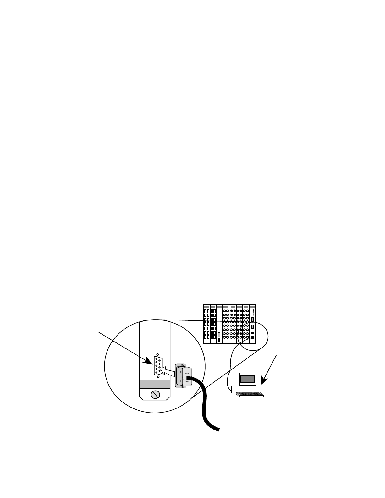
2.1 MANAGEMENT TERMINAL CONFIGURATION
You can access Local Management by attaching a management terminal
(or a modem) at the COM 2/Console port on the front of the management
module (see Figure 2-1). The port supports Digital Equipment Corporation
VT200 or VT300 series terminals or a PC software emulation of those
terminals.
MMAC-8FNB
Console Port
Local
Managem
TOKEN RING
C
O
N
S
O
L
E
Console
Figure 2-1. Local Management Terminal Attachment
2-1
Page 13

ACCESSING LOCAL MANAGEMENT
2.1.1 VT200 or VT300 Series Terminal Setup
If you have a VT200™ or VT300™ series terminal, press F3 to access the
Setup Directory. Table 2-1 lists the setup requirements for the
management terminal.
Table 2-1. Terminal Setup Requirements
Menu Function Selection
Display Setup: Columns 80 Columns
Controls Interpret Controls
Auto Wrap No Auto Wrap
Text Cursor Cursor
General Setup: Mode VT 100,
7 bit control
Cursor Keys Normal Cursor Keys
Communications
Setup:
Keyboard Setup: Keys Typewriter Keys
Transmit Transmit = 9600
Receive Receive = Transmit
Bits, Parity 8 Bits, No Parity
Stop Bit 1 Stop Bit
Local Echo No Local Echo
Port Data Leads Only
Auto
Answerback
Margin Bell Margin Bell
Warning Bell Warning Bell
No Auto Answerback
2-2
Auto
Answerback
No Auto Answerback
Page 14

ACCESSING LOCAL MANAGEMENT
2.2 CONFIGURING THE TERMINAL CABLE
Local management can be accessed by direct connection to a management
terminal by using the RS232 cable and one of the three conversion
connectors shipped with the TRMM/TRMMIM. Two converters are
labeled according to the type of terminal (VT Series and PC) they can be
used with. The converter labeled Modem is used for module-to-modem
connections.
The VT Series connector converts the RJ-45 connector on the cable to a
25-pin female connector, the PC connector converts the RJ-45 connector
to a 9-pin female connector, and the Modem connector converts the RJ-45
connector to a 25-pin male connector.
2.2.1 Pinout Configurations
The pinout configuration for a 9-pin to 25-pin (VT series connection) cable
is listed as follows.
9-Pin Male Connector
(Module End) (Terminal End)
Pin 2 (Transmit) to Pin 3 (Receive)
Pin 3 (Receive) to Pin 2 (Transmit)
Pin 5 (Signal Ground) to Pin 7 (Signal Ground)
Pin 7 (Request to Send) to Pin 5 (Clear to Send)
Pin 8 (Clear to Send) to Pin 20 (Data Terminal Ready)
to
25-Pin Female Connector
The pinout configuration for a 9-pin to 9-pin (PC connection) cable is
listed as follows.
9-Pin Male Connector
(Module End) (Terminal End)
to
9-Pin Female Connector
Pin 2 (Transmit) to Pin 2 (Receive)
Pin 3 (Receive) to Pin 3 (Transmit)
Pin 5 (Signal Ground) to Pin 5 (Signal Ground)
Pin 7 (Request to Send) to Pin 8 (Clear to Send)
Pin 8 (Clear to Send) to Pin 7 (Request to Send)
2-3
Page 15

ACCESSING LOCAL MANAGEMENT
NOTE
: If using a PC with a 25-pin connector, attach a DB-9 to DB-25
converter to the PC to enable LM access connection.
The pinout configuration for a 9-pin to 25-pin (Modem connection) cable
is listed as follows.
9-Pin Male Connector
(Module End) (Modem End)
Pin 2 (Transmit) to Pin 2 (Transmit)
Pin 3 (Receive) to Pin 3 (Receive)
Pin 5 (Signal Ground) to Pin 7 (Signal Ground)
Pin 7 (Request to Send) to Pin 4 (Request to Send)
Pin 8 (Clear to Send) to Pin 8 (Carrier Detect)
to
25-Pin Male Connector
2.2.2 Connecting the Console Cable to a Terminal
To establish a connection between the TRMM/TRMMIM and the
management terminal:
1. Attach the male 9-pin connector to the RS232 port labeled COM 2, or
CONSOLE, on the front of the management module.
2. Attach the female end (25-pin for a VT series terminal or 9-pin for
PCs, as applicable) to the RS232 COMM port on the terminal.
2.3 ACCESSING LOCAL MANAGEMENT
The TRMM/TRMMIM supports only one LM session (from either a
management terminal, modem, or Telnet) at a time. See Section 2.3.1 for
information about LM access restrictions.
To access Local Management:
1. Power on the MMAC in which the management module is installed.
2. Power on the terminal. After a brief warm-up, the Password screen
appears (see Figure 2-2).
2-4
Page 16

ACCESSING LOCAL MANAGEMENT
TRMM LOCAL MANAGEMENT
Cabletron Systems, Incorporated
P.O.Box 5005
Rochester, NH 03867-5005
(603) 332-9400
(c) Copyright Cabletron Systems, Inc. 1994
Flash Image Version: 03.00.05
Boot EPROM Version: 02.01.00
Board Revision: 12
Enter User Password:
Figure 2-2. Local Management Password Screen
3. Enter the Local Management password as follows:
A. Type the password into the
default password is the
Enter User Password:
Return
key.
field.The
Your level of access to Local Management is determined by the
community name that you use for the password. Local
Management is initially shipped with a default Super-user
password of the Return key. You can establish a new Super-user
password at the Community Table screen. Refer to Section 4.2 for
more information.
B. Press
Return
. If you enter an invalid password, the password
prompt remains on screen allowing you to enter the correct
password.
When you enter the correct password, the MAIN MENU appears as shown
in Figure 2-3, indicating that Local Management is ready for operation.
2-5
Page 17

ACCESSING LOCAL MANAGEMENT
TRMM LOCAL MANAGEMENT Flash Image Version: 03.00.05
MAIN MENU
DEVICE SETUP
DEVICE STATUS
DEVICE STATISTICS
MIB NAVIGATOR
SNMP TOOL
EXIT LM
Figure 2-3. Local Management MAIN MENU Screen
NOTE
: To view POWER UP DIAGNOSTIC tests, power on the
TRMM/TRMMIM after first establishing the terminal connection.
2.3.1 LM Access Restrictions
The module can support only one LM session at a time, regardless of the
methods being used to access it. When attempting to open a second LM
session with the module, the second user will be notified by a screen
display (Figure 2-4) that a session is already in effect and will be presented
with the option to disconnect the current user.
To execute a response option:
Y
• Type
disconnect the current LM user and press
or y to disconnect the current LM user or N or n to not
Enter
. A message
confirming that the current user is being disconnected appears on the
Y
screen after a
or y response.
2-6
Page 18

ACCESSING LOCAL MANAGEMENT
A TRMMIM Local Management Session is currently in use.
(This prompt will time out in 60 seconds)
Would you like to disconnect that user? Y
Disconnecting other user. Please wait ...
Figure 2-4. Option to Disconnect Current User Screen
However, the first user disconnected since the TRMM/TRMMIM has been
reset will receive an invitation to reconnect only once. If the first user who
was disconnected bumps the other user out to reconnect and then gets
bumped out again, the first user will have to first re-attach the management
terminal to the module to become eligible to reconnect to LM.
If a third user attempts to access LM while a second user is already
negotiating for a session, the third user will simply be refused connection.
2-7
Page 19

CHAPTER 3
USING LOCAL MANAGEMENT
This chapter describes how to work with LM screen fields. It also
discusses the function of each available selection from the MAIN MENU
Screen.
3.1 WORKING WITH LM SCREEN FIELDS
LM screens contain the following types of fields:
• Editable
select from available discrete values.
• Command
changes to memory, exiting a screen, viewing another screen, and so
on.
• Static
structure, identification, or context for the screens and the fields within
them.
An active editable field is always set in boldface, and additionally, those
enclosed in parentheses or brackets indicate fields that offer selections.
Use the following steps to alter editable fields:
1. Move the cursor to the desired field in the window using the Up, Left,
Right, or Down Arrow keys, as applicable, to highlight the field. The
cursor flashes in reverse video to indicate the selected field.
2. Type the new value into the field or use the spacebar to select (or
toggle) from values available from the field. The old value will be
replaced.
: These fields allow you to either type in a discrete value or
: These fields initiate executable functions such as saving
: These fields cannot be modified and serve only to provide
Incorrect entries (e.g., field value exceeded) are blocked and the field
remains at its original value.
3. Press the Enter key. The new value will be entered into the field.
3-1
Page 20

USING LOCAL MANAGEMENT
4. Highlight the SAVE command, where applicable, at the bottom of the
screen, and press the Enter key. The new values will be saved to
memory.
3.2 THE MAIN MENU SCREEN
The MAIN MENU screen (shown in Figure 2-3) is the initial point for
accessing all screens and commands.
The following selections are available from the MAIN MENU screen.
DEVICE SETUP
This option accesses another menu screen – the DEVICE SETUP menu
screen. There are several screens available from this menu that allow you
to configure the TRMM/TRMMIM. These include:
• SYSTEM LEVEL
TRMM/TRMMIM, including the Date and Time set at its internal
the
clock and addressing information such as the
–This screen lets you assign operating parameters to
IP address and Subnet
Mask.
• SNMP COMMUNITY NAMES
– This screen allows you to specify
the SNMP Community Names which will be granted access to the
TRMM/TRMMIM, as well as the level accorded each name (Read
Only, Read-Write, Super-user).
• SNMP TRAPS
– As an SNMP device, the TRMM/TRMMIM can
authenticate an SNMP request and issue traps correspondingly. The
SNMP TRAPS screen lets you enable the TRMM/TRMMIM to issue
trap/alarms, and specify the IP addresses of network management
stations that will receive these traps.
• RING SECURITY
– You can use this screen to build a list of MAC
addresses that will be allowed to insert into the
TRMM/TRMMIM-controlled ring and specify security options to take
effect when an unauthorized station attempts to insert into the ring
(Alarm to management, or Alarm and station removal).
• BOOT GATEWAY
downloads over routers with Proxy-ARP disabled. The BOOT
3-2
– The TRMM/TRMMIM supports firmware
Page 21

USING LOCAL MANAGEMENT
GATEWAY screen lets you input the IP address of the router used to
reach the file server for the download.
DEVICE STATUS
This option accesses another menu screen – the DEVICE STATUS menu
screen. There are two screens available from this menu that allow you to
view the TRMM/TRMMIM’s status. These include:
• CHASSIS STATUS VIEW
- This selection lets you view the
configuration, ring speed, and type of each token ring board currently
inserted in the MMAC; monitor the operational or administrative
status of all ports; individually enable or disable ring or station ports
on a board, or collectively enable all ports on a board; set the boards
in your MMAC chassis to management or auto mode; and enable or
disable FNB MUX connections, which attach a board to, or detach it
from, its neighbors; or activate the BYPASS MUX.
• COMPONENT STATUS VIEW
– This selection shows all the
TRMM/TRMMIM’s current components.
DEVICE STATISTICS
The DEVICE STATISTICS Screen lets you view ring performance
statistics and ring configuration information.
SNMP TOOL
With the SNMP TOOL selection, you can browse through MIBs by
cycling, walking, or stepping through them. You can also perform GET
operations on individual MIB OIDs as well as SET operations (assuming
you have the correct Community Name access) and set parameters for
initiating image downloads from remote servers.
3-3
Page 22

CHAPTER 4
THE DEVICE SETUP MENU
The DEVICE SETUP menu allows you to assign the following:
• System Level parameters for the TRMM/TRMMIM (including its
System Date and Time, SNMP Agent IP address and Subnet Mask,
Beacon recovery parameters, and a Locally Administered FNB MAC
Address).
• The SNMP Community Names used to access the TRMM/TRMMIM
through local or remote management.
• The IP addresses of network management workstations to which the
TRMM/TRMMIM will issue traps.
• The entries into the ring security database that establishes which
stations can access the TRMM/TRMMIM-controlled ring.
• The IP address of the router over which firmware can be downloaded
to the TRMM/TRMMIM from a file server.
To access the DEVICE SETUP menu from the MAIN MENU, highlight
the DEVICE SETUP option and press Enter. The DEVICE SETUP
menu (Figure 4-1) will appear.
To exit the DEVICE SETUP menu, use the arrow keys to highlight
RETURN at the bottom of the screen and press Enter.
NOTE: Please note that the FLASH DOWNLOAD screen is not supported
at this time.
4-1
Page 23

THE DEVICE SETUP MENU
TRMM LOCAL MANAGEMENT Flash Image Version: 03.00.05
DEVICE SETUP
SYSTEM LEVEL
SNMP COMMUNITY NAMES
SNMP TRAPS
RING SECURITY
FLASH DOWNLOAD
BOOT GATEWAY
RETURN
Figure 4-1. The DEVICE SETUP Menu
4.1 THE SYSTEM LEVEL SCREEN
The SYSTEM LEVEL screen, shown in Figure 4-2, displays the
TRMM/TRMMIM’s MAC address and allows you to set the following
parameters:
• IP Address
• Subnet Mask
• Enable Beacon Recovery, including the number of retries, and the
retry interval
• System Date/System Time
• Locally Administered FNB MAC address
To access the SYSTEM LEVEL screen from the DEVICE SETUP menu
screen, highlight the SYSTEM LEVEL option and press Enter.
The following sections explain each field on the SYSTEM LEVEL screen
and instruct you on how to use them.
4-2
Page 24

THE DEVICE SETUP MENU
TRMM LOCAL MANAGEMENT Flash Image Version: 03.00.05
SYSTEM LEVEL
System Date: 01/01/89 System Time: 00:36:18
IP Address Subnet Mask
SNMP Agent 134.141.147.112 255.255.0.0
COM1 [ UPS ]
COM2 [CONSOLE ]
Enable Beacon Recovery: [YES]
Number of Retries (000-100, 999:infinite): 004
Retry Interval: (000-999): 021
FNB MAC Address
Physical: 00-00-B8-50-63-61
Locally Administered: 40-00-B8-50-63-61
SAVE RETURN
Figure 4-2. The SYSTEM LEVEL Screen
4.1.1 System Date
This field displays the date currently set at the TRMM/TRMMIM.
To edit this field:
1. Highlight the field.
2. Type in the date using the mm/dd/yy format.
3. Press Enter. If the date is valid, the “OK” message appears.
If the date is invalid, the message “Unable to set date...”appears.
Re-enter the date in the correct format.
4. If the date is correct, highlight the SAVE command at the bottom of
the screen and press Enter. The “SAVED” message appears on the
screen indicating that your changes have been saved to memory.
4-3
Page 25

THE DEVICE SETUP MENU
4.1.2 System Time
This field displays the time currently set at the TRMM/TRMMIM.
To edit this field:
1. Highlight the field.
2. Type in the time using the hh:mm:ss (24-hour) format.
3. Press Enter. If the time is valid, the “OK” message appears.
If the time is invalid, the “Unable to set time...” message appears.
Re-enter the time using the correct format.
4. If the time is correct, highlight the SAVE command at the bottom of
the screen and press Enter. The “Saved” message appears on the
screen, indicating that your changes have been saved to memory.
4.1.3 IP Address
This field displays the Internet Protocol (IP) address, which acts as a
logical identifier on the network, currently assigned to the management
module. This is needed for SNMP network management capability. The IP
address is expressed in dotted decimal notation (four decimal values
between 0 and 255, separated by a period, e.g., 123.123.123.123).
With the correct security access, you can edit the IP address as follows:
1. Highlight the IP Address field.
2. Type the address into this field. The format for this entry is dotted
decimal notation (xxx.xxx.xxx.xxx, with the value of xxx ranging
from 0 to 255). The screen beeps if non-numerics or adjacent dots are
entered. If the entry does not have three separator dots, it will be
rejected.
3. Press Enter. The new IP address is displayed. The natural subnet mask
for the user is also generated and displayed. Read the following section
for more information on the subnet mask.
4. Highlight the SAVE command and press Enter. The “Saved”
message will appear. The changes are saved to memory and will take
effect immediately.
4-4
Page 26

THE DEVICE SETUP MENU
4.1.4 Subnet Mask
Subnets are logical divisions of the network (by routers or gateways) that
serve to isolate groups of devices. A subnet mask is used by a device to
determine whether a destination address exists within its own subnet and
thus can be reached directly, or whether it is unknown to the device, and
therefore must be delivered to a router (as specified by the device’s IP
routing table).
You will need to set the subnet mask field if your TRMM/TRMMIM is on
a subnetwork and will be issuing SNMP traps. The subnet mask
determines which side of a router the receiving workstations are on.
A subnet mask essentially acts as a filter for destination IP addresses. It is
a 32-bit quantity (four binary octets) in which all bits that correspond to the
network portion (both Internet site and subnet identifying bits) of the
device’s IP address are set to 1, and all bits that correspond to the host
portion are set to 0.
The TRMM/TRMMIM will perform a logical AND operation to a
destination trap IP address with the subnet mask to determine which
portion of the address identifies the network/subnetwork. The
TRMM/TRMMIM then compares the result on a bit-to-bit basis with the
network identifying bits in its own IP address. If the network portions
match, the TRMM/TRMMIM transmits the trap onto its subnetwork. If
they do not match the TRMM/TRMMIM transmits the trap through a
router or gateway.
NOTE: Consult your Network Administrator prior to setting the Subnet
Mask if you are unsure of its use.
To set a subnet mask:
1. Highlight the Subnet Mask field.
2. Type the desired mask into the field using dotted decimal notation.
The format for this entry is xxx.xxx.xxx.xxx, with values of xxx
ranging from 0-255.
3. Press Enter. If an illegal mask was entered, the entry is blocked and
the field remains at its original value.
4-5
Page 27

THE DEVICE SETUP MENU
4. Highlight SAVE at the bottom of the screen and press Enter. The
message “Saved” will appear. The changes are saved to memory, and
will take effect immediately.
4.1.5 Enable Beacon Recovery
The Enable Beacon Recovery field indicates the current status of the
Automated Beacon Recovery Process (ABRP) at the device. YES
indicates that the ABRP is currently active at the device, NO that the
ABRP is inactive at the device.
To modify the Enable Beacon Recovery field:
1. Highlight the field.
2. Select (using the spacebar or the Enter key) either YES or NO.
3. Highlight the SAVE command and press Enter to commit changes to
memory. A message confirming your selection appears.
If the standard IEEE 802.5 beaconing process fails to restore
communication on a network (connected to an MMAC hub) that is down
because of LAN hardware or cable failures, ABRP provides a secondary
means of network recovery. The TRMM/TRMMIM, as the management
station, matches address information within the beacon frames (i.e., that of
the beaconing station and its NAUN) to its own station list (i.e., the board
and port indexes of stations connected to the MMAC). The
TRMM/TRMMMIM then checks the “fault domain” or the region of the
network between the two failing ports.
While the two ports are undergoing the standard beaconing process, the
TRMM/TRMMIM checks to see if a port between the two failing ports is
physically linked to the MMAC without being mapped as part of a ring
network (e.g., someone inserted a device into the ring that was non-token
ring compatible). If this is the case, the TRMM/TRMMIM automatically
shuts down the port on the MMAC, and runs a verification check to
confirm that the unmapped port was removed.
If no extraneous linked port was found, the TRMM/TRMMIM waits for
the standard beacon recovery process to fail, then triggers ABRP in two
steps. The first step is to disable each port in the fault domain, beginning
with the NAUN port and working to the beaconing source port. If this fails
4-6
Page 28

THE DEVICE SETUP MENU
to remove the fault, the TRMM/TRMMIM begins a second process based
on a physical search of the hub.
During the second step, the TRMM/TRMMIM individually bypasses each
module to isolate the one with the fault (as evidenced by ring recovery on
bypass). When the module with the fault is identified, the module is
reinserted, and the ports are turned off one by one until the ring recovers
again. The last port turned off is considered the failing port. All previously
turned off ports are turned back on.
Once ABRP is completed, the TRMM/TRMMIM generates traps to the
remote management station on the network which will pinpoint the
problem’s cause, including:
• the beaconing adapter’s address
• its NAUN address
• beacon type
• port(s) and/or module bypassed
• duration that the ring beaconed
The network manager must then enable the faulty port before it can be used
again. This prevents a user from rebooting a problem station which may
bring the ring down.
4.1.6 Number of Retries
This field lets you specify the number of times you want the
TRMM/TRMMIM to retry enabling a port disabled during a beaconing
situation.
The factory-set default value for the Number of Retries field is 4. Selection
values are described as follows:
• 0 Disable ring port retries
• 1-100 Retry ring port n times
• 999 Infinite retries
• 101-998 Not accepted
4-7
Page 29

THE DEVICE SETUP MENU
To assign a Number of Retries value:
1. Highlight the Number of Retries field.
2. Type the desired value into the field and press Enter.
3. Highlight the SAVE command and press Enter. The confirmation
message, “Number of Retries Set,” will appear. The changes are saved
to memory and will take effect immediately.
4.1.7 Retry Interval
This field lets you specify the interval between retries. Interval values must
be specified as multiples of 7 (e.g., 14, 21, 28, ........., 980, 987, 994).
Values entered that are not divisible by seven will be rounded to the
nearest dividend of seven.
The factory-set default is 21 seconds. Selection values are described as
follows:
• 0 Disable ring port retries.
• 1-999 n seconds delay between retries.
To assign a Retry Interval:
1. Highlight the Retry Interval field.
2. Type the desired value into the field and press Enter.
3. Highlight the SAVE command and press Enter. The confirmation
message, “Retry Interval Set,” will appear. The changes are saved to
memory and will take effect immediately.
4.1.8 FNB MAC Address
This field displays both the Physical and Locally Administered Media
Access Control addresses, which identify the TRMM/TRMMIM at the
physical layer of a Token Ring network.
Physical
This read-only field reflects a “globally administered address” – that is, the
6-byte address hard-coded into the TRMM/TRMMIM. A hard-coded
address is set at the factory and is unique to each device on the network. In
4-8
Page 30

THE DEVICE SETUP MENU
terms of ring management, a hard-coded address is considered globally
administered because all ring stations will use it by default. Each byte is
identified in bit order starting with the most significant bit.
Locally Administered
This field lets you locally administer, or assign, an FNB MAC address,
overriding the physical default address.
To assign a Locally Administered FNB MAC address:
1. Highlight the Locally Administered field (showing by default the
Physical FNB MAC address).
2. Type the desired address into the field and press Enter. The format for
this entry is 40-00-00-00-00-00, with values of 0 ranging from 0-9 and
A-Z for all but the first two values (use 40 for the first two values).
3. Highlight SAVE at the bottom of the screen and press Enter. The
“Saved” message will appear. The changes are saved to memory, and
will take effect immediately.
4.2 THE SNMP COMMUNITY NAMES SCREEN
This screen allows you to establish the SNMP Community Names (or
passwords) used for access privileges to the TRMM/TRMMIM. To access
the SNMP COMMUNITY NAMES screen (Figure 4-3) from the
DEVICE SETUP menu screen, highlight the SNMP COMMUNITY
NAMES option and press Enter.
Community names serve two purposes: they act as a password to Local
Management and they serve as a security means to control SNMP
management access to the TRMM/TRMMIM.
You control access to the TRMM/TRMMIM by establishing up to three
levels of security authorization (Read Only, Read-Write, and Super-user).
If you have Super-user access, you can change the existing passwords by
changing the community names.
NOTE: All community names assigned in the SNMP COMMUNITY
NAME screen are passwords to Local Management. Only the community name
assigned Super-user access is accorded full read/write privileges to Local
Management.
4-9
Page 31

THE DEVICE SETUP MENU
TRMM LOCAL MANAGEMENT Flash Image Version: 03.00.05
SNMP COMMUNITY NAMES
Component Name Community Name Access
Chassis Mgr public READ-ONLY
Chassis Mgr public READ-WRITE
Chassis Mgr public SUPER-USER
SAVE RETURN
Figure 4-3. The SNMP COMMUNITY NAMES Screen
Remember, too, that Community Names are also used for the purposes of
remote SNMP management. A management station can only monitor and
control a device to the extent accorded the Community Name it uses to
contact the device.
If you have Super-user access, you can change all existing passwords to
the device by altering the COMMUNITY NAMES screen.
Do not forget Super-user names, or else you will not have full management
privileges to your TRMM/TRMMIM.
The following sections briefly describe each field on the SNMP
COMMUNITY NAMES screen and instruct you on how to use them.
4.2.1 SNMP COMMUNITY NAMES Screen Fields
Component Name
This field displays the TRMM/TRMMIM Chassis Manager and
corresponding community names.
4-10
Page 32

THE DEVICE SETUP MENU
Community Name
This field displays the user-defined name through which a user can open
the local management interface with the TRMM/TRMMIM, and the
inherent level of access associated with that password.
Access Policy
This field indicates the access status accorded each community name. Any
community name declared here acts as a password to Local Management.
Descriptions of each access code are listed below:
• Read-Only
: This allows full read-only access to Local Management,
excluding view access to the Super-User name. The message
“AUTHORIZATION ACCESS DENIED” appears over the
Super-User name.
• Read-Write
: This allows you to read and write to Local Management
fields, excluding write privileges to the IP Address, Subnet Mask, and
Community Names, Boot Gateway, and read privileges to the
Super-User Community Name. The message “AUTHORIZATION
ACCESS DENIED” appears over the Super-User name.
• Super-User
: This allows read-write access to all modifiable
parameters including Community Names, IP Addresses, Traps, and
SNMP objects.
4.2.2 Editing the Community Name Field
To edit the Community Name field (with Super-User access only):
1. Highlight the Community Name field corresponding to the desired
level of TRMM/TRMMIM access.
2. Type the password, up to 32 characters in length, into the field.
3. Highlight the SAVE command at the bottom of the screen and press
Enter. The “SAVED” message appears, indicating that your changes
have been saved to memory.
4-11
Page 33

THE DEVICE SETUP MENU
4.2.3 Exiting the SNMP Community Names Screen
To exit the SNMP COMMUNITY NAMES screen:
1. Highlight the RETURN option at the bottom of the screen.
2. Press Enter. The DEVICE SETUP menu screen appears.
4.3 THE SNMP TRAPS SCREEN
The SNMP TRAPS Screen allows you to designate which remote
management stations will receive trap alarms from the TRMM/TRMMIM.
To access the SNMP TRAPS screen from the DEVICE SETUP menu
screen, highlight SNMP TRAPS option and press Enter. The SNMP
TRAPS screen shown in Figure 4-4 appears.
The following sections provide a brief explanation of each field on the
SNMP TRAPS screen and instructions on how to use them.
TRMM LOCAL MANAGEMENT Flash Image Version: 03.00.05
SNMP TRAPS
Trap Destination Trap Community Name Enable Traps
0.0.0.0 <CR> N
0.0.0.0 <CR> N
0.0.0.0 <CR> N
0.0.0.0 <CR> N
0.0.0.0 <CR> N
0.0.0.0 <CR> N
0.0.0.0 <CR> N
0.0.0.0 <CR> N
SAVE RETURN
Figure 4-4. SNMP TRAPS Screen
4-12
Page 34

THE DEVICE SETUP MENU
4.3.1 SNMP TRAPS Screen Fields
Trap Destination
Indicates the IP Address of the workstation that will receive trap alarms
from the TRMM/TRMMIM.
Trap Community Name
Displays the user-defined name of the SNMP Community String which
will be included in traps issued from the TRMM/TRMMIM.
Enable Traps
This field allows you to enable the transmission of SNMP trap messages.
4.3.2 Setting SNMP Traps
To set SNMP traps:
1. Highlight the Trap Destination field.
2. Type in the IP address of the device that will receive trap alarms from
the TRMM/TRMMIM and press Enter. The format for this entry is
xxx.xxx.xxx.xxx, with the value of xxx ranging from 0 to 255.
3. Highlight the Trap Community Name field.
4. Type in the community name of the device and press Enter.
5. Highlight the Enable Traps field.
6. Type Y (yes) to send alarms from the TRMM/TRMMIM to the
workstation or N (no) to prevent alarms from being sent.
7. Highlight the SAVE command at the bottom of the screen and press
Enter. The “SAVED” message appears, indicating that your changes
have been saved to memory.
4-13
Page 35

THE DEVICE SETUP MENU
4.3.3 Exiting the SNMP TRAPS Screen
To exit the SNMP TRAPS screen:
1. Highlight the RETURN option at the bottom of the screen.
2. Press Enter. The DEVICE SETUP menu screen appears.
4.4 THE RING SECURITY SCREEN
The Ring Security screen allows you to control access to the Token Ring
network. When you enable ring security in Alarm Only mode, the
TRMM/TRMMIM stores the MAC address of each station on the token
ring network in a secure database or “allowed list.” Only stations on the
allowed list can enter the ring. The TRMM/TRMMIM can store up to 250
station MAC addresses on the allowed list. The TRMM/TRMMIM retains
the allowed list in its battery-backed Non-Volatile Random Access
Memory (NVRAM). When you power up or reset the TRMM/TRMMIM,
all MAC addresses will be retained and ring security is re-enabled
automatically.
You can append the allowed list by temporarily disabling ring security,
then re-enabling it using the Alarms Only feature. The TRMM/TRMMIM
acts as the Ring Security Monitor for the ring and provides security for the
entire ring.
NOTE: You should enable only one TRMM/TRMMIM per ring for Ring
Security.
You can select two modes of ring security; Alarm Only and
Alarm/Remove. In the Alarm Only mode, new stations can enter the ring,
but a “Station Added” trap/alarm (including the MAC address of the
station) notifies the Network Management Station (NMS) of the event.
The trap/alarm includes the new station’s MAC address so that the
network manager can decide if the new station should be allowed on the
ring.
The Alarm/Remove mode sends a “Remove MAC Frame Command” to
new stations attempting to enter the ring, and a “Station Removed”
trap/alarm (including the MAC address of the station) to the NMS
informing it of the action taken. If, after three attempts, the station cannot
4-14
Page 36

THE DEVICE SETUP MENU
be removed from the ring, a “Remove Station Failure” trap/alarm is sent to
the NMS.
A third default mode, Disabled, allows stations to enter the ring with no
security action taken.
To access the RING SECURITY screen from the DEVICE SETUP screen,
highlight the RING SECURITY option, then press Enter. The RING
SECURITY Screen shown in Figure 4-5 appears.
To exit the RING SECURITY screen, highlight the RETURN menu
command and press Enter.
4.4.1 Ring Security Screen Definitions
The following section provides a brief explanation of each field and
command on the RING SECURITY screen.
TRMM LOCAL MANAGEMENT Flash Image Version: 03.00.05
RING SECURITY
STATION ADDRESS
00-00-B8-50-63-61
Stn Edit 00-00-00-00-00-00 [ Add ] Security Mode [ Disabled ]
SAVE/EXECUTE RETURN
Figure 4-5. The RING SECURITY Screen
Station Address
This field lists the MAC address of each station on the ring security
allowed list. The list holds up to 250 MAC addresses.
4-15
Page 37

THE DEVICE SETUP MENU
Stn Edit
The Stn Edit command lets you add or delete stations from the allowed list.
Use the Stn Edit command for single entry edits to the allowed list.
Security Mode
This command lets you set the Security Mode for the ring. You can select
from among the following Security Modes:
• Disabled
: This is the factory default setting. Use this option to
temporarily disable ring security so that new stations can enter the
ring.
• Alarm Only
: In this mode, new stations can enter the ring, but a
“Station Added” trap/alarm is sent to the Network Management
Station. This trap message is only sent once, and it includes the new
station’s MAC address so that the network manager can decide if the
new station should be allowed on the ring.
If you temporarily disable ring security to allow new users to enter the
ring, you can use the Alarm Only mode to re-enable ring security.
When you select the Alarm Only mode, the TRMM/TRMMIM stores
the MAC address of each station on the ring in the allowed list. This
saves you from entering MAC addresses one at time using the Stn Edit
command.
• Alarm/Remove
: This is the highest level of ring security, which will
lock the ring to new stations. The Alarm/Remove mode sends a
“Remove MAC Frame” command to a new station attempting to enter
the ring, and a trap/alarm to the NMS informing it of the action taken.
If, after three attempts the station cannot be removed from the ring, a
trap/alarm is sent to the NMS informing it that the station could not be
removed.
SAVE/EXECUTE
This command saves all security mode changes to the
TRMM/TRMMIM’s NVRAM. You must use the SAVE/EXECUTE
command for your changes to take effect.
4-16
Page 38

THE DEVICE SETUP MENU
NEXT_SCREEN
Use this command to scroll to the next screen of the allowed stations
database list.
PREVIOUS_SCREEN
Use this command to scroll back to the previous screen of the allowed
stations database list.
RETURN
Use this command to exit the RING SECURITY screen and return to the
DEVICE SETUP screen.
4.4.2 Working with the RING SECURITY Screen
Ensure that your network meets the requirements and conditions specified
in the TRMM/TRMMIM Installation and User’s Guide before you initiate
ring security.
You must also set up the TRMM/TRMMIM’s SNMP TRAPS screen to
designate which Network Management Stations receive trap/alarms (refer
to the prior section describing the SNMP TRAP screen). This ensures that
trap/alarms generated by ring security arrive at the appropriate destination.
Building the Allowed List
The factory default setting for the Security Mode field is Disabled. Ensure
that the Security Mode is set to Disabled before you build the allowed list.
To build the allowed list:
1. Highlight the Security Mode field.
2. Press Enter to toggle through selections (Disabled, Alarm Only,
Remove/Alarm). Select the Alarm Only option.
3. Highlight the SAVE/EXECUTE command.
4. Press Enter. The TRMM/TRMMIM enables ring security and
generates the allowed list.
5. To view the allowed list, refresh the RING SECURITY screen by
exiting and then re-enter the screen.
4-17
Page 39

THE DEVICE SETUP MENU
Adding Stations to the Station Address Allowed List
To add stations one at a time to the Station Address allowed list:
1. Highlight the Stn Edit field.
2. Press Enter to clear the field.
3. Type the MAC address of the station you want to add in the
00-00-00-00-00-00 format and press Enter. To delete characters use
the Backspace key.
4. Use the arrow keys to highlight the Add/Del field.
5. Press Enter to toggle selections. Select the Add option.
6. Highlight the SAVE/EXECUTE command.
7. Press Enter. The station’s MAC address appears on the screen.
Deleting Stations from the Station Address Allowed List
To delete stations from the Station Address allowed list:
NOTE: You must set ring security to the Alarm/Remove mode to effectively
delete a station from the allowed list and keep it off the ring. If you delete
a station from the allowed list while in the Alarm Only mode, the station
can re-enter the ring and its MAC address will reappear in the allowed
list.
1. Highlight the Stn Edit field.
2. Press Enter to clear the field.
3. Type in the MAC address of the station you want to delete in the
00-00-00-00-00-00 format and press Enter. To delete characters, use
the Backspace key.
4. Highlight the Add/Del field.
5. Press Enter to toggle selections. Select the Del option.
6. Highlight the SAVE/EXECUTE command.
7. Press Enter. The station’s MAC address is deleted from the screen.
4-18
Page 40

THE DEVICE SETUP MENU
Changing the Ring Security Mode
To change the Security Mode:
1. Highlight the Security Mode field.
2. Press Enter to toggle selections (Disabled, Alarm Only,
Remove/Alarm). Select the desired option.
3. Highlight the SAVE/EXECUTE command and press Enter. The
TRMM/TRMMIM enables the selected mode of ring security.
4.5 THE BOOT GATEWAY SCREEN
The TRMM/TRMMIM supports firmware downloads across routers with
Proxy-ARP disabled. The BOOT GATEWAY screen lets you specify the
IP address of the router used to reach the file server for the download.
TRMM LOCAL MANAGEMENT Flash Image Version: 03.00.05
BOOT GATEWAY
IP Address
0.0.0.0
SAVE RETURN
Figure 4-6. The BOOT GATEWAY Screens
To assign an IP address:
1. Highlight the IP Address field.
2. Type the address into the field. The format for this entry is dotted
decimal notation (xxx.xxx.xxx.xxx, with the value of xxx ranging
from 0 to 255). The screen beeps if non-numerics or adjacent dots are
4-19
Page 41

THE DEVICE SETUP MENU
entered. If the entry does not have three separator dots, it will be
rejected.
3. Press Enter. The new IP address is displayed.
4. Highlight the SAVE command and press Enter. The “Saved”
message will appear. The changes are saved to memory and will take
effect immediately.
Refer to the router’s manual for instructions on how to input the IP address
of the file server for the download into the router’s setup file.
4-20
Page 42

CHAPTER 5
THE DEVICE STATUS MENU
The DEVICE STATUS menu screen provides two selections, the
CHASSIS STATUS VIEW screen and the COMPONENT STATUS
VIEW screen.
The CHASSIS STATUS VIEW screen lets you:
• View the configuration, ring speed, and type of each token ring
module currently inserted in the MMAC.
• Monitor and manage the operational status of all ports.
• Convert Station ports to Ring Out ports.
• Individually enable or disable ring or station ports on a module, or
collectively enable all ports on a module.
• Set the modules in your MMAC chassis to either management or
automatic operational mode.
• Enable, disable, or bypass Flexible Network Bus (FNB) Multiplexer
(MUX) connections.
The COMPONENT STATUS VIEW screen provides a read-only screen
that shows all the TRMM/TRMMIM’s current components.
To access the DEVICE STATUS screen from the MAIN MENU screen,
highlight the DEVICE STATUS option and press Enter. The DEVICE
STATUS menu screen shown in Figure 5-1 appears.
To exit the DEVICE STATUS menu screen, highlight the RETURN
command at the bottom of the screen and press Enter.
5-1
Page 43

THE DEVICE STATUS MENU
TRMM LOCAL MANAGEMENT Flash Image Version: 03.00.05
DEVICE STATUS
CHASSIS STATUS VIEW
COMPONENT STATUS VIEW
RETURN
Figure 5-1. DEVICE STATUS Menu Screen
5.1 THE CHASSIS STATUS VIEW SCREEN
The CHASSIS STATUS VIEW screen supports three functional modes:
• OPERATIONAL (Figure 5-2) – for monitoring the operational status
of the modules managed by a TRMM or a TRMMIM
• ADMINISTRATIVE (Figure 5-3) – for controlling the functions of
modules managed by a TRMM or a TRMMIM
• RING OUT ENABLE (Figure 5-4) – for changing Station ports to
Ring Out (RO) ports of modules managed by a TRMM or a TRMMIM
To access the CHASSIS STATUS VIEW screen from the DEVICE
STATUS menu screen, highlight the CHASSIS STATUS VIEW option
and press Enter. The CHASSIS STATUS VIEW screen shown in
Figure 5-2 appears.
5.1.1 Selecting a Chassis Status View Mode
Figure 5-2 shows OPERATIONAL mode screens depicting the Local
Management (LM) view for the TRMM and also for the TRMMIM when
5-2
Page 44

THE DEVICE STATUS MENU
both are installed in the same MMAC and managing separate rings within
it.
TRMM LM VIEW
TRMM LOCAL MANAGEMENT Flash Image Version: 03.00.05
CHASSIS STATUS VIEW
8 7 6 5 4 3 2 1
TR_24A TR_10R TRR4AT TRMMIM TRR4AT TR_24A TRMM
|---| |---> <---> <---| |---> <---> <---|
16 Mb/s 16 Mb/s 16 Mb/s
1 ENB 1 ENB
2 ENB 2 ENB
3 ENB 3 ENB
4 ENB 4 ENB
5 ENB 5 ENB
6 ENB 6 ENB
7 ENB 7 ENB
8 ENB 8 ENB
9 ENB 9 ENB
10 ENB 10 ENB
11 ENB 11 ENB
12 ENB 12 ENB
MGMT MGMT
NEXT [ OPERATIONAL ] [ REFRESH 3sec ] RETURN
TRMMIM LM VIEW
TRMMIM LOCAL MANAGEMENT Flash Image Version: 03.00.05
CHASSIS STATUS VIEW
8 7 6 5 4 3 2 1
TR_24A TR_10R TRR4AT TRMMIM TRR4AT TR_24A TRMM
|-B-| |---> <---> <---| |---> <---> <---|
16 Mb/s 16 Mb/s 16 Mb/s 16 Mb/s
1 ENB 1 ENB 1 ENB
2 ENB 2 ENB 2 ENB
3 ENB 3 ENB 3 INS
4 ENB 4 ENB 4 ENB
5 ENB 5 ENB 5 ENB
6 ENB 6 ENB 6 ENB
7 ENB 7 ENB 7 ENB
8 ENB 8 ENB 8 ENB
9 ENB 9 ENB 9 ENB
10 ENB 10 ENB 10 ENB
11 ENB RI WRP 11 ENB
12 ENB RO WRP 12 ENB
MGMT MGMT MGMT
NEXT [ OPERATIONAL ] [ REFRESH 3sec ] RETURN
Figure 5-2. CHASSIS STATUS VIEW Screens (OPERATIONAL Mode)
As Figure 5-2 illustrates, a management module’s LM control extends
only to those modules (and their ports) on the same FNB backplane that it
occupies, even though you can see that modules composing another ring
5-3
Page 45

THE DEVICE STATUS MENU
are also installed in the MMAC. Accordingly, to control a ring supported
by another management module, you must access LM from it.
Selecting a Screen Mode
NEXT [ OPERATIONAL ] [ REFRESH 3sec ] RETURN
The Screen Mode Status field, located at the bottom of the screen, shows
whether the screen mode view is currently set to ADMINISTRATIVE,
OPERATIONAL, or RING OUT ENABLE.
To select a screen mode:
1. Highlight the Screen Mode Status field.
2. Toggle to the desired selection and press Enter. The selected screen
mode appears.
Figure 5-3 shows an example ADMINISTRATIVE mode screen.
TRMM LOCAL MANAGEMENT Flash Image Version: 03.00.05
CHASSIS STATUS VIEW
8 7 6 5 4 3 2 1
TR_24A TR_10R TRR4AT TRMMIM TRR4AT TR_24A TRMM
|---| |---> <---> <---| [|--->] [<--->] <---|
16 Mb/s 16 Mb/s 16 Mb/s
1 [ ON] 1 [ ON]
2 [ ON] 2 [ ON]
3 [ ON] 3 [ ON]
4 [ ON] 4 [ ON]
5 [ ON] 5 [ ON]
6 [ ON] 6 [ ON]
7 [ ON] 7 [ ON]
8 [ ON] 8 [ ON]
9 [ ON] 9 [ ON]
10 [ ON] 10 [ ON]
11 [ ON] 11 [ ON]
12 [ ON] 12 [ ON]
[MGMT] [MGMT]
NEXT ENABLE ALL PORTS [ ADMINISTRATIVE ] [ REFRESH 3sec ] RETURN
Figure 5-3. CHASSIS STATUS VIEW Screen (ADMINISTRATIVE Mode)
5.1.2 Describing Static Screen Fields
The CHASSIS STATUS VIEW screen contains fields that provide static,
or read-only, fields that provide information about the configuration and
operational status of modules in the MMAC.
5-4
Page 46

THE DEVICE STATUS MENU
Module Type
TR_24A TR_10R TRR4AT TRMMIM TRR4AT TR_24A TRMM
This field identifies the module type installed in each MMAC slot.
Table 5-1 provides a list of some modules typically installed in an MMAC
supporting a Token Ring network.
Table 5-1.
Abrrev. Module T ype Description
TRMM TRMM Token Ring Management Module
TRMMIM TRMMIM Token Ring Management Media Interface
Module
TR_12 TRMIM-12 12-port STP passive concentrator (DB-9)
TR_10R TRMIM-10R 10-port STP passive concentrator
w/RI & RO ports (DB-9)
TR_22 TRMIM-22 12-port UTP concentrator (RJ-45)
TR_20R TRMIM-20R 10-port UTP concentrator w/RI&RO ports
(RJ-45)
TR_22A TRMIM-22A 12-port UTP active concentrator (RJ-45)
TR_24A TRMIM-24A 24-port UTP concentrator (RJ-45)
TR_42A TRMIM-42A 12-port STP active concentrator
(shielded RJ-45)
TR_44A TRMIM-44A 24-port STP active concentrator
(shielded RJ-45)
TRR_A TRRMIM-A Active repeater module (FO & STP)
TRR_2A TRRMIM-2A 12-port UTP active repeater (RJ-45)
TRR_4A TRRMIM-4A 12-port STP active repeater (RJ-45)
TRF_26 TRFMIM-26 6-port multimode fiber optic concentrator
TRB TRBMIM-T Token Ring Bridge/Management module
ETW ETWMIM Ethernet/Token Ring WAN Bridge
SNACT1 SNACMIM-12 SNA conversion module
5-5
Page 47

THE DEVICE STATUS MENU
Module Number
8 7 6 5 4 3 2 1
This field displays the MMAC slot number occupied by a module.
Ring Speed
|---> <---> <---|
16 Mb/s 16 Mb/s 16 Mb/s
1 ENB 1 ENB
This field shows the ring speed at which the module is currently operating
(4 or 16 Mb/s). See the TRMM/TRMMIM Token Ring Management
Modules Installation Guide for instructions on how to physically set either
module’s ring speed switch.
Port Index
1 [ ON] 1 [ ON]
2 [ ON] 2 [ ON]
This field shows the index number of the Station, or RI/RO, port interface
on the module. Use the NEXT/PREVIOUS commands as described in
Section 5.1.7 to cycle to and from port index views.
5.1.3 Setting the FNB/BYPASS MUX Configuration
|---| |---> <---> <---| |---> <---> <---|
The FNB/BYPASS MUX field illustrates the configuration of the FNB or
BYPASS Multiplexer which connects Token Ring modules to the
backplane. Each MIM slot supports a left and right
and a BYPASS
MUX connection (excluding the TRMM/TRMMIM).
FNB MUX connection,
Note that every FNB MUX disconnection isolates MIMs on each side of
the break. Therefore MIMs are not linked in a single ring unless all left and
right FNB MUXes are attached.
5-6
Page 48

THE DEVICE STATUS MENU
Possible FNB multiplexer configurations include:
• Attached Left (<––––|) – that is, connected via the backplane to the
module on its immediate left, but not to the right.
• Attached Right (|–––>) – that is, connected via the backplane to the
module on its immediate right, but not to the left.
• Attached Left/Right (<--->) – that is, connected via the backplane to
the modules to its immediate left and right.
• Detached Left/Right (|–––|) – that is, disconnected from any module to
its left or right, via the backplane.
• Bypassed (<-B ->) - that is, all station ports (and in some instances ring
ports) are bypassed to form a self-contained ring on the module.
However, neighboring MIMs will still be attached via the FNB
backplane. The TRMM and the TRMMIM cannot be bypassed.
• Bypassed Right (<-B -|) - that is, the module is bypassed by the module
to its right, but connected to the module to its left.
• Bypassed Left (|-B ->) - that is, the module is bypassed by the module
to its left, but connected to module to its right.
To configure the FNB or Bypass MUX:
1. Select the ADMINISTRATIVE mode.
2. Highlight the MUX field for the desired module.
3. Toggle between the possible FNB/BYPASS MUX configurations and
press Enter to execute the change.
5.1.4 Setting Port Status Fields
1 [ OFF] 1 [ ON]
2 [ OFF] 2 [ ON]
The Port Status field shows a port’s current operational status.
Use the following steps to selectively modify a port’s operational status
from the ADMINISTRATIVE mode:
1. Highlight the desired Port Status field.
2. Toggle to a port setting.
5-7
Page 49

THE DEVICE STATUS MENU
3. Press Enter to execute the change.
The Chassis View ADMINISTRATIVE mode screen shows ports as either
ON (administratively enabled) or OFF (administratively disabled).
The OPERATIONAL mode screen shows Station (Stn) ports as either:
• ENB (Enable) – The port is enabled, but the attached station is not
inserted onto the ring. Enabling a port permits the attached station to
enter the ring.
• B (Bypass) – The port is bypassed (the attached station is not
operational and the port is disabled). Disabling a port makes insertion
impossible.
• LNK
(Link) – The port is disabled and the attached station is
operational.
• INS (Inserted) – The port is enabled and the attached station is
operational (inserted onto the ring).
The OPERATIONAL mode screen shows Ring In/Ring Out (RI/RO) ports
as either:
ACT (Activated): The ring port is ENABLED and connected to the main
trunk cabling of the ring.
WRP (Wrapped): The associated ring port is in the wrap state. In the wrap
state, there is no access to the main trunk. The primary ring is connected
(wrapped) to the backup ring at the port isolating the selected port from the
ring. WRP is set manually by disabling the ring port or automatically upon
detection of a fault on the attached trunk segment on modules with
auto-wrap detection.
In the RING OUT ENABLE mode, ports can be designated as either STN
(Station) or RO (Ring Out) ports as shown in Figure 5-4.
5-8
Page 50

THE DEVICE STATUS MENU
TRMM LOCAL MANAGEMENT Flash Image Version: 03.00.05
CHASSIS STATUS VIEW
8 7 6 5 4 3 2 1
TR_24A TR_10R TRR4AT TRMMIM TRR4AT TR_24A TRMM
|---| |---> <---> <---| |---> <---> <---|
16 Mb/s 16 Mb/s 16 Mb/s
RI 13 [STN]
14 [STN]
15 [STN]
16 [STN]
17 [STN]
18 [STN]
19 [STN]
20 [STN]
21 [STN]
22 [RO]
23 [RO]
24 [RO]
MGMT MGMT
PREVIOUS [ RING OUT ENABLE ] [ REFRESH 3sec ] RETURN
Figure 5-4. RING OUT ENABLE Mode
5.1.5 Enabling All Ports
NEXT ENABLE ALL PORTS [ ADMINISTRATIVE ] [ REFRESH 3sec ] RETURN
Use the ENABLE ALL PORTS field from the ADMINISTRATIVE
screen mode to globally enable all ports under management of the
TRMM/TRMMIM.
To enable all ports:
1. Highlight the ENABLE ALL PORTS field.
2. Press Enter to execute the command. The changes take effect
immediately.
5.1.6 Setting a Module’s Operational Mode
12 ENB 12 ENB
[AUTO] [MGMT]
This field can be changed from the ADMINISTRATIVE screen. It
indicates the operational mode of the module: Management Mode
5-9
Page 51

THE DEVICE STATUS MENU
(MGMT) or Automatic Mode (AUTO). MGMT indicates that hardware
defaults can currently be overridden by local or remote management.
AUTO indicates that the module will operate according to hardware
defaults. The TRMM/TRMMIM will always operate in the MGMT
Mode.
To select an operational mode:
1. Highlight the Operational Mode field.
2. Toggle to a mode setting.
3. Press Enter to execute the change. The change takes effect
immediately.
5.1.7 Controlling the Screen View
Use the NEXT/PREVIOUS fields to cycle to and from a view of Port
Indexes not shown in the current screen.
The NEXT Field
NEXT ENABLE ALL PORTS [ ADMINISTRATIVE ] [ REFRESH 3sec ] RETURN
Use this selectable field to cycle to the next available screen (e.g., to view
Port Index Numbers 13-24).
To scroll to the next screen:
1. Highlight the NEXT field.
2. Press Enter to execute the command.
The PREVIOUS Field
PREVIOUS ENABLE ALL PORTS [ ADMINISTRATIVE ] [ REFRESH 3sec ] RETURN
Use this field to scroll to a previous screen (e.g., to view Port Index
Numbers 1-12).
1. Highlight the PREVIOUS field.
2. Press Enter to execute the command.
5-10
Page 52

THE DEVICE STATUS MENU
5.1.8 Setting the Screen Refresh Interval
Use the REFRESH
Nsec field from the ADMINISTRATIVE mode screen
to set the screen refresh (or screen parameter updates) interval
(from 3 to 10 seconds).
NEXT ENABLE ALL PORTS [ ADMINISTRATIVE ] [ REFRESH 3sec ] RETURN
To set the REFRESH interval:
1. Highlight the field.
2. Toggle to an interval number and press Enter.
5.2 THE COMPONENT STATUS VIEW SCREEN
The Component Status View screen (Figure 5-5) is a read-only screen that
displays TRMM/TRMMIM’s operating system and associated
components. Components are software applications or resources/functions
which are registered in the TRMM/TRMMIM.
Each component can be given separate Community Name access (via
SNMP TOOLS, or through a remote management application, such as
Remote LANVIEW/Windows’ MIBTree utility).
TRMM LOCAL MANAGEMENT Flash Image Version: 03.00.05
COMPONENT STATUS VIEW
COMPONENT NAME
Chassis Mgr
Local Mgmt
Protocol Stack
SNMP Agent
RMON
TRMM Telnet
Network 1
Network 2
Network 3
REFRESH 3sec RETURN
Figure 5-5. The COMPONENT STATUS VIEW Screen
5-11
Page 53

THE DEVICE STATUS MENU
The following MIB components are possible:
• Chassis Mgr
• Local Mgmt
• Protocol Stack
• SNMP Agent
• RMON
– The entity that controls the MMAC chassis.
– The entity for TRMM/TRMMIM LM.
– The entity for the device driver protocol stack.
– The entity for the SNMP management agent.
– Indicates that RMON (Remote Network Monitoring) is
present.
• TRMM (or TRMMIM) Telnet
• Network (1,2, ....,
n) – Indicates the number of LANs ( or individual
– The entity for Telnet.
rings) currently configured in the MMAC.
To exit the COMPONENT STATUS VIEW screen:
1. Highlight the RETURN command at the bottom of the screen.
2. Press Enter. The DEVICE STATUS screen appears.
5-12
Page 54

CHAPTER 6
THE DEVICE STATISTICS SCREEN
The DEVICE STATISTICS screen, shown in Figure 6-1, displays ring
performance statistics and TRMM/TRMMIM configuration information.
To access the DEVICE STATISTICS screen from the MAIN MENU
screen, highlight the DEVICE STATISTICS option and press Enter.
To exit the DEVICE STATISTICS screen, highlight RETURN and press
Enter.
6.1 DESCRIBING DEVICE STATISTICS FIELDS
The following sections provide brief descriptions of informational fields
on the DEVICE STATISTICS screen.
TRMM LOCAL MANAGEMENT Flash Image Version: 03.00.05
DEVICE STATISTICS (DELTA)
INTERFACE: 1
RING INFORMATION
Frames Received: 639 Active Monitor Addr: 00-00-B8-88-75-ED
KBytes Received: 45 Ring Status: Normal
Errors Received: 0 Ring Number: 0
Beacon States: 0 Stations on Ring: 5
Ring Purges: 0 Ports Enabled: 36
Active Monitor Changes: 0 Ring Speed (Mb/s): 16
ISOLATING ERRORS NON-ISOLATING ERRORS
Line Errors: 0 Lost Frame Errors: 0
Burst Errors: 0 Frame Copied Errors: 0
AC Errors: 0 Rcvr Congestion Errors: 0
Abort Transmit Errors: 0 Token Errors: 0
Internal Errors: 0 Frequency Errors: 0
ACCUMULATE TOTAL REFRESH 3sec RETURN
Figure 6-1. The DEVICE STATISTICS Screen
6.1.1 Interface Field
This field displays the network (or FNB) interface. This field is always 1
for the TRMM/TRMMIM.
6-1
Page 55

THE DEVICE STATISTICS SCREEN
6.1.2 Counter Mode Field
DEVICE STATISTICS (DELTA)
The Counter Mode field displays the current counter mode. See
Section 6.2 for a description about counter modes and how to use them.
6.1.3 Total Fields
Frames Received
This field displays the total frames detected on the ring since the
TRMM/TRMMIM was last powered on or reset.
KBytes Received
This field displays the kilobyte sum of all frames detected on the
TRMM/TRMMIM since it was last powered up or reset.
Total Errors Received
This field displays the total Isolating and Non-Isolating Errors detected by
the TRMM/TRMMIM.
Beacon States
This field displays the total beacon states detected by the
TRMM/TRMMIM. Stations transmit beacons when they detect bit
streaming or signal loss on the ring.
Ring Purges
This field displays the total ring purge frames transmitted by the active
monitor.
Active Monitor Changes
This field displays the number of times a different station has been active
monitor.
6-2
Page 56

THE DEVICE STATISTICS SCREEN
6.1.4 Ring Information Fields
Active Monitor Address
This field displays the MAC address of the current Active Monitor. The
Active Monitor is responsible for initiating recovery procedures from
various error situations.
Ring Status
This field lists the current status of the ring being monitored by the
TRMM/TRMMIM. Possible status conditions are Unknown, Closed,
Normal, Purge, Contention, Beaconing, or Lobe Fail.
• Unknown
– indicates the state of the ring cannot be detected by the
management station.
• Closed
– indicates that the management station is not inserted into the
ring, and therefore cannot determine the ring state.
• Normal
– indicates the ring is running with no problems, and tokens
are being detected by the management station.
• Purge
– indicates that the active monitor has issued a ring purge
command. Communications will be restored when a new token is
released.
• Contention
– indicates that the ring has entered into active monitor
contention process to determine a new active monitor for the ring.
• Beaconing
– indicates that the management station has detected a
beacon frame.
• Lobe Fail
– indicates that a station failed the lobe self-test when it
attempted to insert into the ring.
Stations on Ring
This field displays the number of stations inserted into the ring.
Ports Enabled
This field displays the number of network lobe ports enabled.
6-3
Page 57

THE DEVICE STATISTICS SCREEN
Ring Speed (M/bs)
This field displays the ring speed.
6.1.5 Isolating Errors Fields
Isolating Errors are “soft” ring errors that report the domain of a fault (that
is, you can isolate the fault’s region to the transmitting adapter, the
receiving adapter, and the components – cabling and wiring concentrators
– between the two).
A soft error can be recovered through normal operation of the Token Ring
protocol. Although soft errors do not cause ring failure, they degrade
performance of the ring network.
Line Errors
This field displays the total line errors detected by the TRMM/TRMMIM.
These are recorded when a receiving station detects a data corruption in a
packet that was initially transmitted as a good packet. Line errors can be
caused by electronic noise on the ring or by other cable problems. A power
surge may cause the data portion of a frame to be corrupted (i.e., for there
to be a non-valid bit between the data’s start and end delimiters) or a Frame
Check Sequence error.
Since these are isolating, you can use a network management package to
narrow the problem to the station downstream from the error (since the
fault may have occurred as it was receiving) or its upstream neighbor
(since the fault may have occurred as it was transmitting).
Burst Errors
This field displays the total burst errors detected by the
TRMM/TRMMIM. Burst Errors occur when a station’s receiver does not
clock an incoming data signal correctly. These errors normally occur when
there is a brief disruption or electronic surge on the cable, which can
happen when stations enter or leave the ring with no phantom current.
This error can also indicate a problem with the receiver of the reporting
node, or the transmitter of its Nearest Active Upstream Neighbor (NAUN),
or the cabling and hub hardware in between them.
6-4
Page 58

THE DEVICE STATISTICS SCREEN
AC Errors
This field displays the total Address Recognized Indicator/Frame Copied
Indicator errors. A faulty node cannot set the address recognized indicator
and/or frame copied indicator bits in the frame which it has copied. This
leaves the downstream node (that reports the error) with an incorrect
NAUN address.
This is usually caused by a problem in the adapter hardware of the NAUN
of the reporting node.
Abort Transmit Errors
This field displays the total abort delimiter frames transmitted by a station.
These occur when a station is loading frames onto a token, but does not
detect an ending delimiter on the token after its access control field
(corrupted token). The station transmits abort delimiters to halt frame
transmission before its expected end-frame sequence.
These occur when a station’s adapter experiences an internal error while it
is in the process of transmitting. This indicates a failing adapter on the
reporting node – possibly because it is overheating in an overloaded
system. The adapter may also issue a hard Internal Error, and remove itself
from the ring.
Internal Errors
This field displays the total internal errors detected by the adapter’s
hardware and/or firmware.
• These are counted as soft errors when the node can recover from the
error and remain on the ring.
• These are counted as hard errors when they cause the adapter to
remove itself from the ring.
In either instance, the error indicates a problem with the adapter hardware
or firmware (possibly an inoperable chipset, timers, or counters). A
common cause is overheating by the adapter.
6-5
Page 59

THE DEVICE STATISTICS SCREEN
6.1.6 Non-Isolating Errors Fields
Non-isolating errors are “soft” error conditions that could have been
caused by any station on the ring, thus their fault domain cannot be
detected.
Lost Frame Errors
These errors occur when a transmitting station’s TRR (Timer, Return to
Repeat) timer expires before the end of its transmitted frame returns. This
timer ensures that the station returns to the data repeat state (e.g., retrieves
the token, strips it of data, and issues a new token to the ring). The Lost
Frame Errors field tracks these non-returned frames.
Lost frames are usually caused by a station entering or leaving the ring as
the frame is circulating, since this throws the ring temporarily out of clock
synchronization.
Frame Copied Errors
Frame Copied Errors are recorded when a station recognizes a frame
addressed to it, and detects that the frame’s Address Recognized Indicator
(ARI) bits are already set 1. This indicates a possible line surge, or that
another station is duplicating its address.
It is virtually impossible to have a ring with duplicate addresses, since the
ring most often will use the hard-coded addresses on ring adapters, and
duplicate addresses are checked for when a station inserts into the ring.
However, a system administrator can pass a locally assigned address to a
station adapter, so it is possible to unintentionally administer a duplicate
address while a device is on the ring.
Another possible cause is transparent bridges on a ring network. When a
frame first enters the net, it assumes that the first frame it receives is on
another network (even though the intended destination may be on the same
net), since its bridge database has not been updated. It will set the ARI bits
and forward frame data across the bridge. The intended station on the same
side of the net as a bridge’s receive port will perceive that the frame has
already been copied.
6-6
Page 60

THE DEVICE STATISTICS SCREEN
Rcvr Congestion Errors
This field displays the total number of Rcvr Congestion Errors. This
indicates a station is receiving/repeating a frame and recognizes a frame
addressed to it, but has no buffer space available for the frame.
This may indicate a poorly performing station, since it is receiving frames
faster than its adapter can copy information from the buffer. Although this
is counted as a non-isolating error (under the assumption that upstream
stations are transmitting data too quickly, rather than the receive station is
copying data too slowly), you can isolate the fault to the reporting station,
and may want to replace its network interface card (NIC) if this is a
frequent occurrence.
Token Errors
This field displays the total number of Token Errors. Token Errors occur
when an active monitor does not see a token circulating on the ring before
its TVX (Timer, Valid Transmission) time expires (e.g., a lost frame error
has occurred), or sees a recirculating frame or token. The active monitor is
then responsible for purging the ring and issuing a new token.
The major cause for token errors is the disruption of ring synchronization
as stations enter or leave the ring. Note that token errors are only reported
by an active monitor.
Frequency Errors
This field displays the total number of frequency errors. This indicates that
the frequency of the incoming signal deviates excessively from the
adapter’s onboard crystal oscillator (i.e., by more than .6%). This could
indicate an error in this node’s oscillator, the active monitor, or any node
in between. Note that it sometimes occurs when a network designed with
UTP cabling exceeds the standard of 72 stations. It also occurs more
frequently when your ring is operating at 16 Mbits/sec. When the node
detects a frequency error, it enters the monitor contention process.
6-7
Page 61

THE DEVICE STATISTICS SCREEN
6.2 SELECTING A COUNTER MODE
The Device Statistics screen lets you view statistics gathered from any
time frame you choose to specify. This section explains how to
pre-determine the amount of statistical data you want displayed.
You can select from either of the following three counter modes:
• ACCUMULATE
– lets you initiate a statistics display for a specified
time frame.
• DELTA
– lets you automatically display statistics since the last the last
screen update (or REFRESH Nsec selection set from the CHASSIS
STATUS VIEW screen).
• TOTAL
– lets you automatically display statistics since the last power
up.
To select a counter mode:
1. Highlight either of the two mode selections (the box below shows
example options).
ACCUMULATE TOTAL REFRESH 3sec RETURN
2. Press Enter to execute the change. The corresponding Counter Mode
field at the top of the screen will change to reflect the selection.
6.2.1 Using the ACCUMULATIVE Mode
Use the ACCUMULATIVE mode to specify a time frame from which you
want to display network statistics.
To specify a time frame:
1. Select the the ACCUMULATIVE mode. The Clear Date and the
Clear Time fields appear near the top of the screen.
Clear Date: 01/01/95 Clear Time: 01:34:55
6-8
Page 62

THE DEVICE STATISTICS SCREEN
The Clear field appears near the bottom of the screen.
ACCUMULATE TOTAL REFRESH 3sec CLEAR RETURN
2. Highlight the Clear field and press Enter. The Clear Date and Clear
Time fields change to reflect the beginning of the time frame from
which you want to view network statistics the next time you select the
ACCUMULATE mode.
6-9
Page 63

CHAPTER 7
THE SNMP TOOLS SCREEN
This chapter describes how to use the SNMP TOOLS screen to access
Management Information Bases (MIBs) supported by the
TRMM/TRMMIM. Your level of security access to the LM component of
the TRMM/TRMMIM may prevent you from accessing some portions of
the device’s MIBs. For example, a user with read-only LM access cannot
view the variables in a MIB which reveal community name access to the
TRMM/TRMMIM.
All explanations provided in this chapter are based on the assumption you
have super-user access (thus full management capability) to the LM
component of the TRMM/TRMMIM. Refer to Section 4.2 for more
information regarding Community Names.
From SNMP TOOLS screen you can:
• View the information associated with a MIB variable specified by its
object identifier (OID).
• View MIB variables in sequence from the original OID that you
requested. You can also view variables by walking or cycling through
several OIDs simultaneously, or stepping through them one by one.
• Edit configurable variables.
To access the SNMP TOOLS screen from the MAIN MENU screen,
highlight the SNMP TOOL selection and press Enter. The SNMP
TOOLS screen shown in Figure 7-1 appears.
7.1 SNMP TOOLS SCREEN FIELDS
The following briefly describes SNMP TOOL screen fields and
commands.
COMMUNITY NAME
This field identifies the Community Name used as a password to the LM
component of the TRMM/TRMMIM.
7-1
Page 64

THE SNMP TOOLS SCREEN
TRMM LOCAL MANAGEMENT Flash Image Version: 03.00.05
SNMP TOOLS
COMMUNITY NAME: public
OID PREPEND: 1.3.6.1
GET SET GETNEXT WALK RECALL OID STEP CYCLES REPEAT
F6 F7 F8 F9
RETURN
Figure 7-1. SNMP TOOLS Screen
OID PREPEND
This field specifies a numerical prefix (OID string) for the MIB variables
of interest supported by the TRMM/TRMMIM. ‘1.3.6.1’ is the default
prefix (iso ⇒ org ⇒ dod ⇒ internet). You can modify this field to
provide a prefix for lower levels of the MIB (SMI) tree.
GET (F6)
This field lets you issue an SNMP GET command to retrieve a value from
a single MIB variable.
SET (F7)
This field lets you issue an SNMP SET command to store a new value in
a modifiable MIB variable.
GETNEXT (F8)
This field lets you retrieve the next variable in sequence from the currently
selected variable (either a new MIB variable or the next instance of the
current variable) without specifying its OID string.
7-2
Page 65

THE SNMP TOOLS SCREEN
WALK
After you have selected a variable in the MIB by its OID, you can use
WALK to scroll through all the remaining MIB variables in sequence.
Using WALK, you span the remainder of the MIB tree viewing each
branch (collection of related MIB variables) and its leaves (the objects and
instances that compose and culminate the branch) in order.
When you initialize a walk, the following fields display on screen.
Specified OID
Size
– Displays the number of bytes needed to store the variable in the
– Provides the numerical identifier (OID) of the variable
TRMM/TRMMIM’s flash EEPROMs
Data Type
Data Value
– Specifies the variable’s type (e.g., int = integer)
– Displays the value associated with that variable as read from
the TRMM/TRMMIM
RECALL OID (F9)
When you perform a GET, GETNEXT, or SET operation, you use
RECALL OID to retrieve from memory the last OID used since the board
was powered-up.
STEP
This field lets you to conveniently walk the MIB, one variable at a time,
by using the Enter key in place of performing continuous GETNEXT
operations. The details for each variable will display on screen.
CYCLES
This field lets you conveniently view a series of MIB variables by
specifying a number of GETNEXT operations to be performed after the
initial identifier is entered, and the period (in seconds) to elapse between
each operation.
REPEAT
This field lets you perform continuous GETs on the specified variable, so
that you can monitor changes in its value.
7-3
Page 66

THE SNMP TOOLS SCREEN
7.2 GETTING AND SETTING VARIABLES
To get a variable:
1. Highlight GET and press Enter (or press F6). “<GET> OID (=|F9)”
will appear.
2. Enter the variable’s OID either by:
A. Typing the full OID string in the <GET> OID field.
B. Typing the part of the OID that occurs after the prepend listed
above, and then pressing Enter (e.g., typing 4.1.3 in the <GET>
OID field, with an existing prepend of 1.3.6.1, would get the
complete OID string of 1.3.6.1.4.1.3).
C. Note that if you type ‘=’ and then type in an OID string, the
prepend will be ignored (e.g., if you enter =4.1.3 in the <GET>
OID field, a get would be issued for the OID string 4.1.3).
D. Pressing F9 to recall the last OID entered into the <GET> OID
field, and then using the keyboard to modify that OID.
3. Press Enter. If that variable is not supported by the
TRMM/TRMMIM’s MIBs, the message “MIB_NO_INSTANCE”
will be returned; otherwise, information displays for that variable’s
data type, length, and value. Refer to Figure 7-2 for sample data from
a GET operation (internet -> mgmt -> mib-2 -> system -> sysDescr).
Note that the information contained in the sample would display
similarly for GETNEXT or STEP operations.
ACCESSED OID: 1.3.6.1.2.1.1.1.
ASCII_LABEL: N/A
DATA TYPE: 0
DATA LENGTH: 32
DECODED DATA: CABLETRON TRMM Revision 3.00.5
Figure 7-2. Sample Output from a GET, GETNEXT, or STEP Operation
X2 {STR}
To get the next variable:
1. Highlight GETNEXT and press Enter (or press F8). “<GETNEXT>
OID (=|F9)” appears.
7-4
Page 67

THE SNMP TOOLS SCREEN
2. Enter the OID and press Enter. If no instance of that variable exists,
you will be notified to that effect; otherwise information displays for
that variable’s data type, length, and value.
Note that you can use the OID prepend or the F9 RECALL command
key as described above.
To set a MIB variable:
1. Highlight SET and press Enter (or press F7). “<SET> OID (=|F9)”
will appear.
2. Type in the variable’s OID and press Enter. If no instance of that
variable exists, you will be informed to that effect; otherwise the
screen displays a “DATA TYPE:” field.
Note that you can use the OID prepend or the F9 RECALL command
key as previously detailed.
3. Enter the variable’s Data Type and press Enter. Possible data types
are:
• integer • string • null
• OID • IP address • counter
• gauge • timeticks • opaque
The screen will then display a “DATA” field.
4. Enter the Data, or value for that variable, and press Enter. If accepted,
“<SET> OPERATION CODE: XXXX <OK>” will display on screen;
otherwise you will see an error message.
Figure 7-3 displays a sample SET operation (internet -> mgmt -> mib-2 ->
system -> sysLocation).
<SET> OID (=|F9): 2.1.1.6.0
{INteger String Null Old IPaddress Counter Gauge Timeticks OPaque}
DATA TYPE (name): Str
Enter H(ex) or A(scii) FOR STRING TYPE: a
SNMP OID DATA: Bognor Regis
<SET> OPERATION CODE: 1 <OK>
Figure 7-3. Sample Input for a SET Operation
7-5
Page 68

THE SNMP TOOLS SCREEN
7.3 SCROLLING THROUGH MIB VARIABLES
The SNMP TOOLS screen allows you to scan a MIB for the variable
information that you need in several ways:
• The WALK command begins at a variable that you specify by OID,
and proceeds to scroll through all remaining variables that are
structured below it in the SMI tree.
• The CYCLE command allows you to specify a number of GetNext
operations to perform after the initial variable is specified by OID.
• The STEP command pages through the MIB, one OID at a time.
• The REPEAT command will continuously perform continuous gets on
the specified OID, so that you can view any change in value.
To walk through:
1. Highlight WALK and press Enter. “<INITIAL> OID (=|F9)” will
appear.
2. Enter the OID and press Enter. LM begins walking through the
sublayers of the MIB available from the specified OID. Each OID
listed displays the specified OID, its size, its data type, and the data
value. Figure 7-4 displays sample results from a WALK operation.
Note that results will appear similarly for a CYCLE operation.
3. Press any key to stop the walk, or wait for “***MIB WALK
COMPLETED***” to appear on the screen.
----------SPECIFIED OID---------- SIZE TYP DATA (HIT ANY KEY TO EXIT)
1.3.6.1.4.1.52.4.1.1.2.5.1.5.1.2 4 STR TRMM
1.3.6.1.4.1.52.4.1.1.2.5.1.5.1.4 4 STR TRMM
1.3.6.1.4.1.52.4.1.1.2.5.1.5.1.5 4 STR TRMM
1.3.6.1.4.1.52.4.1.1.2.5.1.5.2.1.1 7 STR BOARD 2
1.3.6.1.4.1.52.4.1.1.2.5.1.5.3.1 7 STR BOARD 3
Figure 7-4. Sample Results from a WALK or CYCLE Operation
To cycle through:
1. Highlight CYCLES and press Enter.
2. Enter the number of OID cycles that you want to scroll through after
“ENTER CYCLE COUNT:” and press Enter.
7-6
Page 69

THE SNMP TOOLS SCREEN
3. Enter how many seconds delay that you want between GETNEXT
requests after “ENTER CYCLE DELAY (secs):”, and press Enter.
4. Highlight GETNEXT and press Enter. Use the down arrow key to
scroll through the Get Next cycles requested.
To step through:
1. Highlight STEP and press Enter. “Specify OID” will appear.
2. Enter the OID (only the suffix is necessary) and press Enter. The
initial OID’s details are displayed including, its size, its data type, and
the data value. Note that data will appear in a similar fashion to a GET
or GETNEXT operation.
3. Press the Enter key to page through the MIB to the next OID.
To repeat:
1. Highlight REPEAT and press Enter. The <GET> prompt will appear.
2. Specify a new OID string, or press F9 to recall the last OID into the
<GET> field.
3. Press Enter. Continuous GET operations will be performed on the
specified OID. The information for the specified variable’s data type,
length, and value will display in a continuous stream, along with the
number of GETs performed.
7.4 INITIATING A FIRMWARE DOWNLOAD
Use the SNMP TOOLS screen to initiate a Flash file download. The user
will need to know the IP address of the TFTP server and the full path name
of the firmware image to be downloaded from that server.
Set the following OIDs as prescribed below in order to properly initiate
and complete the download.
• ctDLForceOnBoot - 1.3.6.1.4.1.52.4.1.5.8.1.1.0
Cabletron’s Download Force On Boot OID determines whether the
module will force a Flash image download at next reset or will boot
from its current Flash file. Set this integer value to 1 to force the
download (or 0 to disable).
7-7
Page 70

THE SNMP TOOLS SCREEN
• ctDLTFTPRequestHost - 1.3.6.1.4.1.52.4.1.5.8.1.4.0
Cabletron’s Download TFTP Request Host OID holds the IP address
of the designated TFTP server. Set it to the IP address of the TFTP
server which contains the image to be downloaded.
• ctDLCommitRAMtoFlash - 1.3.6.1.4.1.52.4.1.5.8.1.2.0
Cabletron’s Download Commit RAM to Flash OID determines
whether the downloaded image will be committed to Flash memory
after a successful download. Set this integer value to 1 to commit the
downloaded image to Flash (or 0 to disable). If not committed to Flash,
the downloaded file will be lost at power-down.
• ctDLTFTPRequest - 1.3.6.1.4.1.52.4.1.5.8.1.5.0
Cabletron’s Download TFTP Request OID holds the full pathname of
the file to be downloaded. Set it to the fully qualified path name of the
image file to be downloaded.
• ctDLInitiateColdBoot - 1.3.6.1.4.1.52.4.1.5.8.1.3.0
Cabletron’s Download Initiate Cold Boot OID is an integer value.
When set to 1, it forces the TRMM to reset and reboot. This OID must
be set last, because the device will reset immediately after processing
this request.
7-8
 Loading...