

Page 1

TRMIM-10R
TOKEN RING
MEDIA INTERFACE MODULE
INSTALLATION GUIDE
The Complete Networking Solution
CABLETRON SYSTEMS, P. O. Box 5005, Rochester, NH 03867-5005
Page 2

NOTICE
NOTICE
Cabletron Systems reserves the right to make changes in specifications and other information contained in this document without prior
notice. The reader should in all cases consult Cabletron Systems to
determine whether any such changes have been made.
The hardware, firmware, or software described in this manual is
subject to change without notice.
IN NO EVENT SHALL CABLETRON SYSTEMS BE LIABLE FOR
ANY INCIDENTAL, INDIRECT, SPECIAL, OR CONSEQUENTIAL
DAMAGES WHATSOEVER (INCLUDING BUT NOT LIMITED TO
LOST PROFITS) ARISING OUT OF OR RELATED TO THIS MANUAL OR THE INFORMATION CONTAINED IN IT, EVEN IF
CABLETRON SYSTEMS HAS BEEN ADVISED OF, KNOWN, OR
SHOULD HAVE KNOWN, THE POSSIBILITY OF SUCH DAMAGES.
Copyright November 1990 by:
Cabletron Systems, Inc.
P.O. Box 5005, Rochester, NH 03867-5005
All Rights Reserved
Printed in the United States of America
Order Number: 9030258 November 90
LANVIEW, Remote LANVIEW Windows, Spectrum,
TRMIM-10R, TRRMIM-16, TRMIM-12, MMAC, and FNB are
trademarks of Cabletron Systems Inc.
IBM is a registered trademark of International Business Machines
Corporation.
i
Page 3

FCC NOTICE
FCC NOTICE
This device complies with Part 15 of FCC rules. Operation is subject
to the following two conditions: (1) this device may not cause harmful
interference, and (2) this device must accept any interference received, including interference that may cause undesired operation.
WARNING: This equipment uses and generates and can radiate
radio frequency energy and if not installed properly and used in
accordance with the instruction manual, may cause interference to
radio communications. It has been tested and found to comply with
the limits for a Class A digital device pursuant to Part 15 of FCC
Rules, which are designed to provide reasonable protection against
such interference in a commercial environment. Operation of this
equipment in a residential area is likely to cause interference in
which case the user at his own expense will be required to take
whatever steps may be necessary to correct the interference.
If this equipment does cause interference to radio or television, which
can be determined by turning the equipment off and on, the user is
encouraged to try to correct the interference by one or more of the
following measures:
• Re-orient the receiving antenna.
• Relocate the MMAC with respect to the receiving antenna.
• Move the MMAC away from the receiver.
• Plug the MMAC into a different outlet so that the MMAC and
the receiver are on different branch circuits.
If necessary, the user should consult the dealer or an experienced
radio/television technician for additional suggestions. The user may
find the following booklet prepared by the Federal Communication
Commission helpful:
“How to Identify and Resolve Radio TV Interference Problems”
This booklet is available from the U.S. Government Printing Office,
Washington D.C. 20402 - Stock No. 004-000-00345-4
ii
Page 4

CONTENTS
CONTENTS
CHAPTER PAGE
CHAPTER 1 INTRODUCTION
1.1 Using This Manual ......................................................................1-1
1.2 The TRMIM-10R ..........................................................................1-2
1.3 Related Manuals ..........................................................................1-4
1.4 Recommended Reading................................................................1-4
1.5 Getting Help.................................................................................1-4
CHAPTER 2 INSTALLATION REQUIREMENTS/
SPECIFICATIONS
2.1 Network Requirements................................................................2-1
2.1.1 Cable Types ........................................................................2-1
2.1.2 Cable Lengths.....................................................................2-2
2.1.3 Attenuation.........................................................................2-3
2.1.4 Impedance...........................................................................2-4
2.1.5 Crosstalk .............................................................................2-4
2.1.6 Maximum Number of Stations ..........................................2-4
2.1.7 Noise ...................................................................................2-5
2.1.8 Temperature .......................................................................2-5
2.2 Operating Specifications..............................................................2-5
2.2.1 Ring Speed ..........................................................................2-5
2.2.2 Connector Types .................................................................2-5
2.2.3 Ring Sequence ....................................................................2-7
2.2.4 LANVIEW LEDs ................................................................2-7
CHAPTER 3 INSTALLING THE TRMIM-10R
3.1 Unpacking the TRMIM-10R........................................................3-1
3.2 Installing the TRMIM-10R into the MMAC...............................3-1
3.3 Attaching Cables to the TRMIM-10R .........................................3-4
3.3.1 Connecting Lobe Cabling ...................................................3-4
3.3.2 Connecting Trunk Cabling ................................................3-6
3.4 Finishing the Installation............................................................3-7
iii
Page 5

CONTENTS
CONTENTS (Cont.)
CHAPTER 4 TESTING AND TROUBLESHOOTING
4.1 Installation Check-Out ................................................................4-1
4.2 Using LANVIEW .........................................................................4-2
APPENDIX A BASIC TOKEN RING NETWORKS
A.1 Basic Token Ring Operation .......................................................A-1
A.2 Design Considerations ................................................................. A-7
APPENDIX B APPLICATIONS
B.1 Adding to an Existing Token Ring Network.............................B-1
B.2 Separate Token Ring Networks in One MMAC .......................B-2
B.3 Token Ring Networks Bridged Together ..................................B-3
B.4 MMAC with Ethernet and Token Ring Simultaneously..........B-3
APPENDIX C CALCULATING RING LENGTH
C.1 Rules for Calculating Cable Lengths ........................................C-1
C.2 Single Wiring Closet Networks .................................................C-2
C.3 Multiple Wiring Closet Networks .............................................C-9
C.4 Calculating Mixed Cable Types ...............................................C-15
iv
Page 6

INTRODUCTION
CHAPTER 1
INTRODUCTION
Welcome to the TRMIM-10R Token Ring Passive Concentrator
Media Interface Module Installation Guide. This guide is
designed to serve as a reference for the installation and
troubleshooting of Cabletron Systems' TRMIM-10R.
The TRMIM-10R is a token ring network concentrator used in
conjunction with Cabletron's Multi Media Access Center (MMAC).
The TRMIM-10R provides ten trunk unit coupling ports and passive
Ring-In and Ring-Out ports. The Ring-In/Ring-Out ports and each of
the TRMIM-10R's ten trunk coupling unit ports support IBM
1, 2, 6, and 9 shielded twisted pair cabling. The TRMIM-10R is IEEE
802.5 compliant, and compatible with IBM products.
Prior to installing and operating the TRMIM-10R, read through this
manual completely to familiarize yourself with its content and to gain
an understanding of the features of the TRMIM-10R. A general
working knowledge of token ring (IEEE 802.5) networks will be
helpful when installing the TRMIM-10R.
Types
1.1 USING THIS MANUAL
Chapter 1, Introduction, covers using this document, briefly
describes features of the TRMIM-10R and token ring, and concludes
with a list of related manuals.
Chapter 2, Installation Requirements/Specifications, lists
network requirements that must be met before you install the
TRMIM-10R and specifications for the TRMIM-10R.
Chapter 3, Installing the TRMIM-10R, describes installing the
TRMIM-10R into the MMAC, attaching station cabling and
connecting the TRMIM-10R to a token ring network.
Chapter 4, Testing and Troubleshooting, includes a description of
LANVIEW, Cabletron Systems' built-in visual diagnostic and
status monitoring system and procedures for verifying the proper
installation of the TRMIM-10R.
Page 1-1
Page 7

INTRODUCTION
Appendix A, Basic Token Ring Networks, covers basic operation
and concepts related to the design of token ring networks.
Appendix B, Applications, presents a variety of network
configurations, showing practical applications for several Cabletron
Systems' token ring products.
Appendix C, Calculating Ring Length, describes methods for
calculating various ring cable lengths for passive devices in a token
ring network.
1.2 THE TRMIM-10R
This section outlines some of the basic features of the TRMIM-10R.
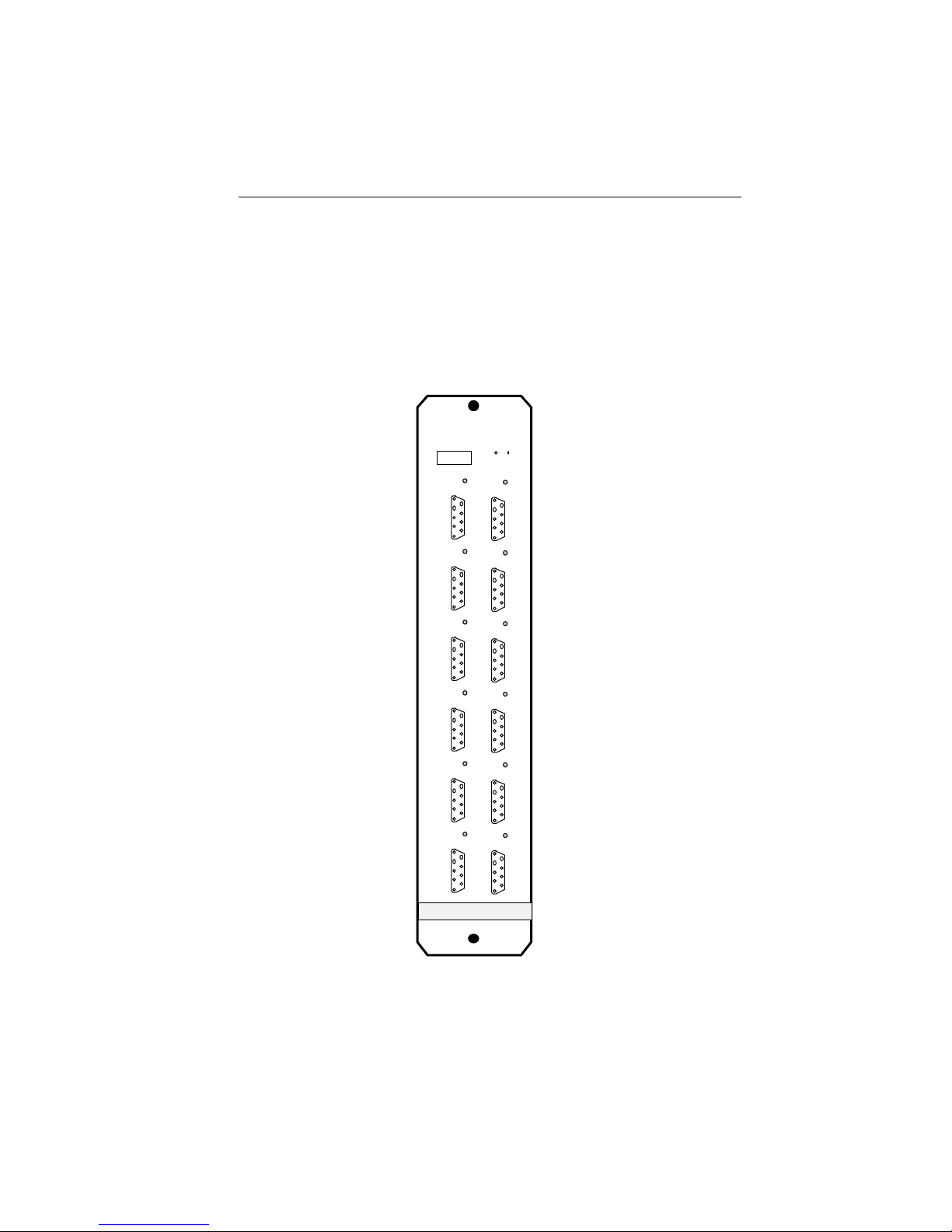
The TRMIM-10R, shown in Figure 1-1, is a Media Interface Module
(MIM) that can be installed into a Cabletron Systems' MMAC (Multi
Media Access Center). The TRMIM-10R functions as a ten port
concentrator module in a token ring network providing passive RingIn and Ring-Out ports and ten trunk coupling ports.
Twelve DB-9 connectors on the front panel of the TRMIM-10R
provide one Ring-In port, one Ring-Out port for connecting the
TRMIM-10R into a token ring network and ten trunk coupling ports
for attaching ten stations.
The TRMIM-10R supports lobe lengths up to 200 meters at 4 Mbit/sec
and 100 meters at 16 Mbit/sec using IBM Type 1 or Type 2 shielded
twisted pair cable. The supported types and lengths of cables are
listed in Chapter 2, Installation Requirements/Specifications.
The Ring-In/Ring-Out ports provide passive trunk connections using
IBM Type 1 or Type 2 shielded twisted pair cable. Trunk cable
lengths must consider Adjusted Ring Length (ARL). Refer to
Appendix C, Calculating Ring Length, to determine trunk cable
length.
The Flexible Network Bus (FNB) provides an internal trunk
connection between multiple Cabletron Systems' Token Ring products
operating at the same ring speed and installed in consecutive slots
within the same MMAC. The FNB is an active interface that
regenerates and retimes ring signals between boards on the FNB.
Page 1-2
Page 8
INTRODUCTION
Several LEDs are located on the front panel of the TRMIM-10R.
These LEDs indicate the ring speed, the detection of a hardware error
in the TRMIM-10R, and the status of TRMIM-10R ports. These
LEDs are a useful tool for quickly diagnosing physical layer problems.
A variety of network manangment tools can be used to control and
monitor the TRMIM-10R, including Cabletron Systems Local
Management, Cabletron Systems Remote LANVIEW Windows, and
Cabletron Systems Spectrum.
TRMIM-10R
7
8
9
10
RI
RO
TOKEN RING
1
2
3
4
5
6
Figure 1-1. TRMIM-10R Token Ring Concentrator
Page 1-3
Page 9

INTRODUCTION
1.3 RELATED MANUALS
The manuals listed below should be used to supplement the
procedures and other technical data provided in this manual. The
procedures in them will be referenced, where appropriate, but will not
be repeated in this document.
Cabletron Systems' Multi-Media Access Center Overview and
Set Up Guide.
Cabletron Systems' TRMIM-12 Token Ring Media Interface
Module Installation Guide.
Cabletron Systems' TRRMIM-16 Token Ring Repeater Media
Interface Module Installation Guide.
1.4 RECOMMENDED READING
The following publications are recommended if more information is
required on implementing a Token Ring network.
Local Area Networks, Token Ring Access Method, IEEE
Standard 802.5
LAN Troubleshooting Handbook, Mark Miller (1989, M&T
Publishing, Inc.)
1.5 GETTING HELP
If you need additional support related to the Cabletron Systems'
token ring products, or if you have any questions, comments or
suggestions related to this manual, please contact Cabletron Systems'
Technical Support at:
Cabletron Systems
35 Industrial Way
P. O. Box 5005
Rochester, NH 03867-5005
Phone: (603) 332-9400
Page 1-4
Page 10

REQUIREMENTS/SPECIFICATIONS
CHAPTER 2
INSTALLATION REQUIREMENTS/
SPECIFICATIONS
Before you attempt to install Cabletron Systems' token ring products,
review the installation requirements and operating specifications
outlined in this chapter. The conditions, guidelines and requirements
described in this chapter must be met to obtain satisfactory
performance from this equipment. The reliability of the network is
determined by the quality of the connections, the length of the cables
and other conditions of the installation.
2.1 NETWORK REQUIREMENTS
The following subsections summarize the network requirements to
operate this equipment.
2.1.1 Cable Types
The TRMIM-10R supports IBM shielded twisted pair cable Types 1,
2, 6, and 9 for Lobe and Trunk cabling. Table 2-1 lists all of the IBM
cable types for reference, but the TRMIM-10R supports Types 1, 2, 6,
and 9 only.
Table 2-1. IBM Cable Types
Type 1 Two shielded twisted pairs (STP) of 22 AWG solid wire
for data. Used for the longest cable runs within the
walls of buildings.
Type 2 Similar to Type 1 data cable, but having four additional
unshielded twisted pairs of 24 AWG solid wire. These
are carried outside of the shield casing and are typically
used for voice communication. Frequently used to wire
cable runs within the walls of buildings.
Page 2-1
Page 11

REQUIREMENTS/SPECIFICATIONS
Table 2-1 (cont.). IBM Cable Types
Type 3 Usually four unshielded twisted pairs (UTP) of 24 AWG
solid wire for data or voice communication. Used for
cable runs in walls of buildings.
Type 5 Two 100/140 µm optical fibers in a single sheath.
Type 6 Two STP of 26 AWG stranded wire for data. This type is
used in patch panels or to connect devices to/from wall
jacks. Attenuation for Type 6 cable is 3/2 x Type 1 cable
(66 m of Type 6 = 100 meters of Type 1).
Type 8 One flat STP of 26 AWG stranded wire for under carpet
installation.
Type 9 Similar to Type 1, but uses 26 AWG solid wire.
Attenuation for Type 9 cable is 3/2 x Type 1 cable (66 m
of Type 9 = 100 meters of Type 1).
2.1.2 Cable Lengths
The TRMIM-10R is a passive concentrator. It neither regenerates
nor retimes ring signals and the cable lengths used for the TRMIM10R must consider the Adjusted Ring Length (ARL). ARL results
from automatic recovery processes that attempt to restore continuity
to a broken ring. The ARL is the longest potential ring length, the
ring that would exist following recovery from a failure of the shortest
ring segment trunk cable. Refer to the discussion of token ring
concepts related to ARL in Appendix A. Appendix C describes how to
calculate cable lengths in your network, giving consideration to ARL.
Considering ARL, two cable lengths must be defined for the TRMIM10R: Lobe Length and Trunk Length. Their combined length defines
the path between two token ring stations and cannot exceed the
maximum drive distance.
• Drive Distance - Drive distance is the limit of reliable signal
propagation without the installation of repeaters in the ring. The
maximum drive distance using STP cabling is 770 meters (2525
feet) at 4 Mbit/sec and 346 meters (1138 feet) at 16 Mbit/sec.
These limits include the combined length of all trunk cables plus
twice the length of the longest lobe cable.
Page 2-2
Page 12

REQUIREMENTS/SPECIFICATIONS
• Lobe Length - This is the physical length of STP cable
connecting a station to the trunk coupling unit (TCU) port on the
TRMIM-10R. The recommended maximum length for the longest
lobe cable is shown in Table 2-2. This is a recommended
maximum because cable length calculations for passive ring
connections described in Appendix C could produce a maximum
lobe length for your network that differs from this limit.
Installing a lobe that exceeds the recommended maximum could
restrict future expansion of the network.
• Trunk Length - This is the physical length of the STP cabling in
the main ring path, from Ring-Out to Ring-In on each of the
attached token ring devices. The cable budget for the trunk
cabling must be determined by performing the calculations
described in Appendix C. In a totally passive ring (no repeaters
or active concentrators, etc. on the ring), the entire trunk length
must be included in calculation of cable lengths. When only a
portion of the ring is passive, the combined length of the trunk
cabling between the active components must be considered in the
cable length calculations.
Table 2-2. Lobe Cabling
Maximum Lobe Length
4 Mbit/sec 16 Mbit/sec
STP (IBM Types 1 & 2) 200 meters 100 meters
STP (IBM Type 6) 30 meters 30 meters
(only for station to wall
jack and patch panels)
STP (IBM Type 9) 130 meters 65 meters
2.1.3 Attenuation
Maximum attenuation for specific cable types according to ring speed,
is shown by Table 2-3. Since there are two possible ring speeds, two
frequencies are listed, namely 4.0 MHz and 16 MHz. The attenuation
values include the attenuation of the cables, connectors, and patch
panels.
Page 2-3
Page 13

REQUIREMENTS/SPECIFICATIONS
Table 2-3. Maximum Cable Attenuation
4.0 MHz 16.0 MHz
STP (IBM Types 1 & 2) 22 dB/km 45 dB/km
STP (IBM Types 6 & 9) 33 dB/km 66 dB/km
2.1.4 Impedance
The characteristic impedances for specific cable types are listed in
Table 2-4. These are typical impedances, and can vary among
different manufacturers of cabling.
Table 2-4. Cable Impedance
Cable Type Characteristic Impedance
STP (IBM Types 1 & 2) 150 ohms (1 MHz to 20 MHz) ±10%
STP (IBM Types 6 & 9) 150 ohms (1 MHz to 20 MHz) ±10%
2.1.5 Crosstalk
Crosstalk is caused by signal coupling between the different cable
pairs contained within a multi-pair cable bundle. In shielded twisted
pair cables, the effects of crosstalk are minimized.
2.1.6 Maximum Number of Stations
Table 2-5 shows the maximum number of stations that can be
inserted into a single ring using STP cabling according to ring speed.
Table 2-5. Maximum Number of Stations
4 Mbit/sec 16 Mbit/sec
Number of Stations 250 stations 136 stations
NOTE: If unshielded twisted pair (UTP) cabling is used with
STP in the same ring, the number of stations is determined by
the UTP specification.
Page 2-4
Page 14

REQUIREMENTS/SPECIFICATIONS
2.1.7Noise
Noise can be caused by either crosstalk or externally induced
impulses. If noise induced errors are suspected, it may be necessary
to re-route cabling away from potential noise sources (motors,
switching equipment, high amperage equipment), or to ensure that
the electrical wiring in the area is properly wired and grounded.
2.1.8 Temperature
The attenuation of PVC insulated cable varies significantly with
temperature. At temperatures greater than 40° C, we strongly
recommend that you use plenum-rated cables to ensure that cable
attenuation remains within specification. Check the cable
manufacturer's specifications.
2.2 OPERATING SPECIFICATIONS
This section includes the operating specifications for the TRMIM-10R.
Cabletron Systems Inc. reserves the right to change these
specifications at any time without notice.
2.2.1 Ring Speed
The TRMIM-10R can be operated at a ring speed of either 4 Mbit/sec
or 16 Mbit/sec. The default ring speed is set by a hardware jumper on
the TRMIM-10R. The ring speed can be changed via a software
selection (refer to the applicable Remote LANVIEW Network
Management Users Guide) that overrides the jumper selection.
2.2.2 Connector Types
• Trunk Coupling Unit Ports - Ten Female DB-9 connectors are
located on the front panel of the TRMIM-10R. They are labeled 1
through 10, corresponding to the ten Trunk Coupling Unit (TCU)
ports. Figure 2-1 shows the pin layout and signal connections for
these connectors.
Page 2-5
Page 15

REQUIREMENTS/SPECIFICATIONS
TCU Ports: Pin Pin Pin
1 TX– 4 Ground 7 Ground
2 Ground 5 RX– 8 Ground
3 Not Used 6 TX+ 9 RX+
TCU PORT
TX-
RX-
1
6
2
3
4
5
TX+
7
Common
Ground
8
RX+
9
FEMALE DB-9 RECEPTACLE
Common Ground
Not Connected
Common Ground
Figure 2-1. TCU Ports Pinouts
• Trunk Connections - Two Female DB-9 connectors for
attaching STP trunk cables are located on the lower left side of
the TRMIM-10R front panel. Figure 2-2 show the signal and pin
assignments for the STP ring interface.
Trunk Ports: Pin Pin
Ring-In 1 RX– (Main Ring) 5 TX– (Backup Ring)
2 Ground 7 Ground
3 Ground 6 RX+ (Main Ring)
4 Ground 8 Ground
9 TX+ (Backup Ring)
Ring-Out 1 TX– (Main Ring) 5 RX– (Backup Ring)
2 Ground 7 Ground
3 Ground 6 TX+ (Main Ring)
4 Ground 8 Ground
9 RX+ (Backup Ring)
RING- IN RING-OUT
FEMALE DB-9 RECEPTACLE
(Main Ring) RX-
Common
Ground
(Backup Ring) TX-
1
2
3
4
5
RX+ (Main Ring)
6
Common
7
Ground
8
TX+ (Backup Ring)
9
FEMALE DB-9 RECEPTACLE
(Main Ring) TX-
Common
Ground
(Backup Ring) RX-
1
2
3
4
5
TX+ (Main Ring)
6
7
Common
Ground
8
RX+ (Backup Ring)
9
Figure 2-2. Trunk Cable Connections
Page 2-6
Page 16

REQUIREMENTS/SPECIFICATIONS
2.2.3 Ring Sequence
The ring sequence on the TRMIM-10R begins at the Ring-In, goes out
to the Flexible Network Bus (FNB) then, after threading through
other attached token ring boards, returns from the FNB to sequence
through the TCU ports (in port number order) and finally out the
Ring-Out port. The following example serves to illustrate the ring
sequence in an MMAC with multiple token ring boards:
Example: TRMIM-22P in slot 1 with ports 2, 5, 8, & 12 in use.
TRMIM-10R in slot 2 with ports 1, 2, 3, 5, and 6 in use.
TRMIM-12 in slot 3 with ports 1, 5, 7, 11, & 12 in use.
All three boards are attached via the FNB.
The ring sequence in this example is from Slot 2, Ring-In port via the
FNB to Slot 3, ports 1, 5, 7, 11, 12, via the FNB to Slot 1 ports 2, 5, 8,
12; then, returning to the TRMIM-10R in Slot 2 threading through
ports 1, 2, 3, 5, and 6, then out the Ring-Out port.
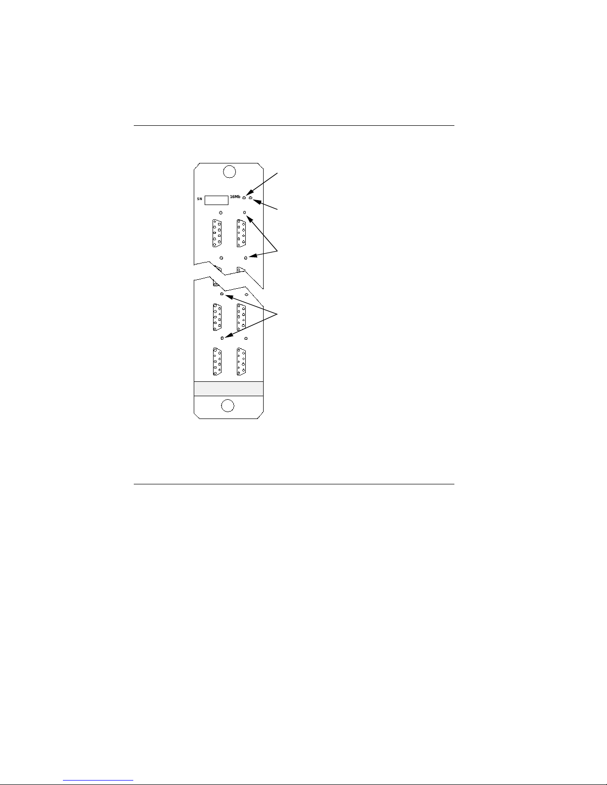
2.2.4 LANVIEW LEDs
There are a number LANVIEW LEDs on the front panel of the
TRMIM-10R. The exact locations for these LEDs are illustrated in
Figure 2-3. Table 2-6 describes the functions for each LED.
Table 2-6. LANVIEW LEDs
Label Color Description
16 Mb Yellow Ring Speed Indicator
ON TRMIM-10R is set for 16 Mbit/sec
OFF TRMIM-10R is set for 4 Mbit/sec
RI/RO Green Ring-In/Ring-Out Status (2)
Status ON Respective ring port is in a non-wrap state
OFF Respective ring port is in a wrap state
ERR Red ON TRMIM-10R hardware error detected
OFF Normal operation
Link Green Link Attached (10 - One LED for each TCU port)
Attached ON The respective port is inserted into the ring.
OFF The respective port is removed (bypassed)
from the ring.
Page 2-7
Page 17
REQUIREMENTS/SPECIFICATIONS
16Mb (Yellow) LED
TRMIM-10R
16Mb
SN
ERR
ERR (Red) LED
17
LINK ATTACHED (Green) LED
(one for each trunk coupling port)
RI
RO
5
6
RING-IN/RING-OUT PORT STATUS (Green) LED
TOKEN RING
Figure 2-3. TRMIM-10R LANVIEW LEDs
SAFETY
WARNING: It is the responsibility of the person who sells the
system to which the TRMIM-10R will be a part to ensure that the
total system meets allowed limits of conducted and radiated
emissions.
This equipment is designed in accordance with UL478, UL910,
NEC 725-2(b), CSA, IEC, TUV, VDE Class A, and meets FCC
part 15, Class A limits.
Page 2-8
Page 18

REQUIREMENTS/SPECIFICATIONS
SERVICE
MTBF (MHBK-217E): >119,951 hrs.
MTTR: <0.5 hr.
PHYSICAL
Dimensions: 13.4D x 11.5H x 2.0W inches
(34.0D x 29.2H x 5.1W centimeters)
(includes front panel)
Weight: 2 lbs. 2 oz.
(963.9 grams)
Page 2-9
Page 19

INSTALLING THE TRMIM-10R
CHAPTER 3
INSTALLING THE TRMIM-10R
This chapter contains instructions for configuring and installing the
TRMIM-10R into a MMAC and includes instructions for connecting
station and trunk cabling. Check that all requirements listed in
Chapter 2, Installation Requirements/Specifications, are met before
installing the MIM.
3.1 UNPACKING THE TRMIM-10R
Prior to installation, unpack and visually inspect the TRMIM-10R for
damage:
1. Carefully remove the TRMIM-10R from the shipping box. Save
the box and materials in the event that the unit has to be repackaged and shipped.
CAUTION: Electro-Static Discharges (ESD) will damage the
TRMIM-10R. Observe all precautions to prevent electrostatic
discharges and when handling the TRMIM-10R, hold only the
edges of the board or the metal front panel. Avoid touching the
components or surface of the TRMIM-10R.
2. Remove the TRMIM-10R from its protective plastic bag and set it
on top of its protective bag in a static free area.
3. Inspect the MIM for physical damage and contact Cabletron
Systems' Technical Support immediately if any problems exist.
3.2 INSTALLING THE TRMIM-10R INTO THE MMAC
The TRMIM-10R is designed to be easily installed into an MMAC
product. When you install the TRMIM-10R, the following guidelines
must be followed:
• Slot 0 of the MMAC is a reserved slot. The TRMIM-10R cannot
be installed into Slot 0.
Page 3-1
Page 20

INSTALLING THE TRMIM-10R
• If the TRMIM-10R is being installed into an MMAC-8, or MMAC8FNB, be sure that a Power Supply Module (PSM or PSM-R) is
installed in the associated rear power supply slot. The PSM or
PSM-R is the source of power for MMAC modules. One PSM or
PSM-R is required for every two MIMs.
NOTE: The PSM-R is a Redundant Power Supply Module, that is
recommended for use with the MMAC-8FNB (equipped with a
Flexible Network Bus).
• To link several Cabletron Systems' Token Ring products that are
installed in the same MMAC, the MMAC must be configured with
a backplane and the boards must be set to the same ring speed
and in consecutive slots.
Install the TRMIM-10R as follows:
1. Position the hardware jumper on the proper pins on the TRMIM10R to select either 4 or 16 Mbit/sec as the default ring speed (see
Figure 3-1). The speed setting affects the number of stations and
the maximum lobe length. Refer to Chapter 2, Installation
Requirements/Specifications for additional information.
NOTE: The network speed is also selectable by software. The
software selection overrides the hardware jumper selection.
2. Power the MMAC chassis off, if it is not already powered off, by
unplugging the AC power cord from the wall outlet.
3. Remove the selected blank panel from the MMAC and slide the
TRMIM-10R (see Figure 3-2) into the MMAC card cage. Be sure
that the board is in the guides at the top and bottom of the card
cage.
4. Secure the module to the MMAC by tightening the knurled knobs.
Failure to firmly secure the MIM may result in improper operation.
5. Power the MMAC chassis on.
Page 3-2
Page 21

4 Mbit/sec
INSTALLING THE TRMIM-10R
Twelve DB-9 Connectors
(Six on mother board, and six on daughter board)
16 Mbit/sec
Network Speed Jumper
J1
MMAC-8
...
J1
Mother board
Daughter board
Figure 3-1. Network Speed Jumper
TRMIM-10R
IRM
TRMIM-10R
Front
Panel
KNURLED KNOBS
BOARD SLOT
TOKEN RING
Figure 3-2. Installing the TRMIM-10R
Page 3-3
Page 22

INSTALLING THE TRMIM-10R
3.3 ATTACHING CABLES TO THE TRMIM-10R
Prior to connecting cables, check that the pinout and maximum cable
lengths throughout the system conform to the requirements described
in Chapter 2, Installation Requirements/Specifications.
The trunk coupling unit (TCU) and Ring-In/Ring-Out trunk ports of
the TRMIM-10R are not sensitive to signal polarity. If the (+) and (-)
lines within a pair are reversed, the network will still function
properly due to the differential Manchester encoding. Operating in
this condition is not recommended. When discovered, the cable
connections should be corrected according to the information provided
in Chapter 2, Installation Requirements/Specifications.
3.3.1 Connecting Lobe Cabling
The physical lobe cable (see Figure 3-3) between the TRMIM-10R and
a token ring station consists of two pairs of wire: a transmit signal
pair (TX+, TX-) and a receive signal pair (RX+, RX-). The transmit
pair from the TRMIM-10R connects to the receive pair of the station
and the receive pair from the TRMIM-10R connects to the transmit
pair of the station. For example, TX+ from the TRMIM-10R connects
to RX+ of the station and RX+ from the TRMIM-10R connects to TX+
on the station. This provides the necessary Crossover or Null Modem
Effect.
Page 3-4
Trunk Coupling Port Token Ring Station
TX+
6
TX–
1
9
RX+
RX–
5
Lobe Cable
RED
GREEN
ORANGE
BLACK
DB-9 Connectors
RX+
6
1
RX–
TX+
9
TX–
5
Figure 3-3. STP Connections
Page 23

INSTALLING THE TRMIM-10R
Attaching STP Lobe Cables to the TRMIM-10R
1. Connect the male DB-9 connector from one end of the STP lobe or
patch panel cable to the desired TCU port on the TRMIM-10R .
2. If a patch panel is being used, connect the other end of the cable
to the appropriate patch panel jack. (Install DB-9 to MIC
adapters as needed.)
3. Repeat this process for each station.
Attaching the STP Lobe Cable at the Station
Cabling at the Token Ring station may require adapter patch cables
to permit mating between the wall plate and the station. Select the
appropriate patch cable: DB-9 at both ends, or DB-9 to Medium
Interface Connector (MIC) (illustrated in Figure 3-4). If an adapter is
used, attach the adapter to the cable before connecting the twisted
pair cable to the station. Connect the wall plate end of the cable to
the wall plate. Connect the other end of the cable to the port on the
token ring station.
3.3.2 Connecting Trunk Cables
The TRMIM-10R Ring-In/Ring-Out ports support STP trunk cable
connections. Connect the STP trunk cables to the TRMIM-10R as
follows:
1. Attach the male DB-9 connector at one end of the STP trunk cable
to its respective Ring-In or Ring-Out port.
NOTE: When only one TRMIM-10R is installed, forming an
independent ring network, wrap jumpers must be installed at the
Ring-In and Ring-Out ports of the TRMIM-10R.
Page 3-5
Page 24

INSTALLING THE TRMIM-10R
2. If a patch panel is being used, connect Ring-In from the patch
panel to Ring-In on the TRMIM-10R and Ring-Out from the patch
panel to Ring-Out on the TRMIM-10R. If connecting directly to
another concentrator, daisy-chain the connections, Ring-In to
Ring-Out, from concentrator to concentrator. For some
installations, DB-9 to MIC adapters may be needed.
3.4 FINISHING THE INSTALLATION
Complete the installation as follows:
1. Be sure the MMAC and the stations are powered on.
2. Check that the LEDs on the MIM and any LEDs on the stations
are indicating normal operation (TRMIM-10R red Error LED off
and no error indications at the stations). If you encounter errors
or abnormal operation, proceed to Chapter 4, Testing and
Troubleshooting.
The green Link Attached LEDs on the MIM should be illuminated
for each station that is inserted into the ring. The yellow 16Mb
LED should only be on if 16 Mbit/sec ring speed is desired.
3. Configure the networking software.
The TRMIM-10R is now ready for operation. Before placing the
network into service, test the installation thoroughly, making sure
that all stations are able to be addressed and that the data is being
relayed without error. Ensure that the networking software is
configured properly to match the installed network.
Page 3-6
Page 25

TESTING AND TROUBLESHOOTING
CHAPTER 4
TESTING AND TROUBLESHOOTING
This section contains procedures to verify the cabling connecting the
TRMIM-10R to the token ring network and any attached stations. A
description of LANVIEW and its function in troubleshooting physical
layer network problems is also provided.
4.1 INSTALLATION CHECK-OUT
Perform the following steps to check-out the installation of the
TRMIM-10R:
1. Be sure that the token ring stations and the MMAC match the
AC power source (120 Vac or 240 Vac) and are powered on.
2. Trace the ring path through the network, to be sure that there
are no breaks in the ring and that it is free from logical design
errors. While tracing the ring:
a. Check each cable connection on the MIM.
b. Verify that the pinout for every connector is correct.
c. Check the cable conductors for continuity. Cable testers are
available for this task.
d. Check each cable connection at patch panels and wall plates.
3. Check the network ring speed:
a. Check that the ring speed matches the station and cable
specifications mentioned in Chapter 2, Installation Re-
quirements/Specifications.
b. Verify all devices on the ring network are set to the same ring
speed. Check all MIMs and stations in the network.
4. Verify that the maximum number of stations and maximum cable
lengths for each station are not exceeded.
Page 4-1
Page 26

TESTING AND TROUBLESHOOTING
When these checks have been successfully completed for each connection to the TRMIM-10R, the MIM is ready for normal operation. If
further problems occur, contact Cabletron Systems' Technical Support.
4.2 USING LANVIEW
LANVIEW is Cabletron Systems' built-in visual diagnostic and status
monitoring system. Using LANVIEW, your network troubleshooting
personnel can quickly scan the LANVIEW LEDs to observe network
status or diagnose network problems, and determine which node or
segment is faulty. The definitions and locations for the front panel
LANVIEW LEDs are illustrated in Figure 4-1.
16Mb (Yellow) LED
ON - Ring speed set for 16 Mbit/sec
TRMIM-10R
SN
16Mb
17
OFF - Ring speed set for 4 Mbit/sec
ERR
ERR (Red) LED
ON - Hardware error detected in
TRMIM-10R
OFF - Normal operation
Page 4-2
LINK ATTACHED (10 - Green) LED
(one for each trunk coupling port)
ON - Respective station is inserted into
the ring.
OFF - Respective station is removed
(bypassed) from the ring.
RING-IN/RING-OUT PORT STATUS (2 - Green) LED
(one for each ring connection)
ON - Respective Ring-In/Ring-Out port is in a
non-wrap state
OFF - Respective Ring-In/Ring-Out port is in a
wrap state
RO
RI
5
6
TOKEN RING
Figure 4-1. TRMIM-10R LANVIEW LEDs
Page 27

TESTING AND TROUBLESHOOTING
• 16 Mb - The Ring Speed LED (Yellow) is lit to indicate that the
TRMIM-10R ring speed is set to 16 Mbit/sec. When this indicator
is not lit, the ring speed is set to 4 Mbit/sec. The ring speed is set
to a default setting by hardware jumper, J1 (refer to Chapter 3,
Installing the TRMIM-10R, for setting this jumper). The
TRMIM-10R is set to the default ring speed at power on. The ring
speed can be changed via local network management software.
• RI/RO Status - The ring status indicators (2, Green) indicate the
state of the Ring-In and Ring-Out ports. The normal condition is
lit, indicating that the respective ring port is in a non-wrap state.
When either indicator is not lit, it indicates that the respective
ring port has been set to the wrap state by network management
software. (The TRMIM-10R does not automatically wrap to
recover from ring segment failure.)
• ERR - The error indicator (Red) should not be lit under normal
operating conditions. When lit this LED indicates the detection of
a TRMIM-10R hardware failure. If the problem persists, contact
Cabletron Systems' Technical Support.
• Link Attached - Ten Link Attached LEDs (Green), one for each
TCU port indicate that the station attached to the respective TCU
port is powered on and inserted into the ring. When a link
attached LED is not lit, the respective port is inactive, and the
station is removed (bypassed) from the ring.
Page 4-3
Page 28

BASIC TOKEN RING NETWORKS
APPENDIX A
BASIC TOKEN RING NETWORKS
This Appendix covers the basic operation and concepts related to
design considerations for token ring networks.
A.1 BASIC TOKEN RING OPERATION
A token ring network is made up of a number of stations electrically
connected to form a continuous loop. Physically, the stations are
usually arranged in a star pattern around a hub or concentrator
module. The hub or concentrator provides ring access for several
stations that are electrically (or optically in the case of fiber optic
media) attached to the ring. The connections at the hub form wiring
drops, called lobes, that extend out to each of the attached stations
and return to the hub (see Figure A-1).
STATION 3
STATION 2
STATION 1
STATION 8
Figure A-1. Typical Token Ring Physical Installation
HUB
STATION 7
STATION 4
STATION 5
STATION 6
Page A-1
Page 29

BASIC TOKEN RING NETWORKS
Basic Token Ring Protocol
This summary briefly covers a basic subset of the overall token ring
access protocol. The IEEE Standard 802.5 provides greater detail on
token ring access methods and should be referenced whenever more
complete information is needed.
Each station attached to the ring is identified by a unique station
address differentiating it from all other stations. When a token ring
station is activated and inserted into a ring, several actions are
initiated to maintain order on the ring. All the active stations enter
into a monitor contention dialogue, resulting in one station (the
highest currently active address) establishing itself as the Active
Monitor (AM). As part of its duties, the AM initializes the ring and
transmits a special message frame called a token.
The token circulates around the ring from station to station. Receipt
of the token grants a station the privilege of accessing the ring to
transmit data. When a station receives a token and uses the
opportunity to transmit information, it appears that the token is
removed from the ring and held by the station for the duration of the
transmission. In reality, the token is modified by the station and
used to create the data frame. The token is divided and the
information is inserted between the modified Access Control (AC)
field, and the Ending Delimiter (ED). Figure A-2 shows the token
and information frame formats. Each station receives the token from
a station preceding it on the ring and either uses it while
transmitting data or passes (transmits) it to the next active station on
the ring. When a station has data to transmit, the station modifies
the token AC field, inserts its data into the frame between the AC
and ED, waits for the transmission to circulate completely around the
ring, strips its own data transmission from the ring, and then
restores the token. A Token Holding Timer (THT) controls the length
of time that any station may retain the token. Here is a typical token
ring sequence:
1. AM initiates the ring and places the token on the ring.
2. Station xxx wants to send some data to station yyy. Station xxx
modifies the token by inserting the information addressed to
station yyy.
Page A-2
Page 30

BASIC TOKEN RING NETWORKS
3. The frame addressed for yyy circulates around the ring. All
stations in the ring examine the frame, checking the address, in
successive order. When the transmission gets to yyy, station yyy
copies the data as it goes past.
4. When the original transmission finishes the trip around the ring
and is seen by station xxx again, station xxx removes the
transmission from the ring. At this time, if station xxx has no
more data to send or if its Token Holding Time (THT) has
expired, station xxx releases the token back onto the ring.
5. The ring is now available for use by another station. The token
resumes its circulation until it reaches the next station that is
waiting to send data. Here, the process will begin again with
that station seizing the token.
Unless an error occurs that disrupts normal token passing, the
original token remains in circulation. Lost tokens are detected by the
AM and appropriate corrective procedures are initiated.
TOKEN FRAME
ACSD ED
INFORMATION FRAME
ACSD ED
Figure A-2. Token Ring Frame Formats
SD - Starting Delimiter (1 octet)
AC - Access Control (1 octet)
FC - Frame Control (1 octet)
DA - Destination Address (2 or 6 octets)
SA - Source Address (2 or 6 octets)
INFO - Information (0 or more octets)
FCS - Frame Check Sequence (4 octets)
ED - Ending Delimiter (1 octet)
FS - Frame Status (1 octet)
DAFC SA FS
INFO
FCS
Page A-3
Page 31

BASIC TOKEN RING NETWORKS
Early Token Release
Early Token Release (ETR) is a second protocol option presented in
the IEEE 802.5 Standard. ETR is an optional protocol that may be
used with 16 Mbit/sec 802.5 token ring networks. It has the
advantage of increasing the efficiency of the ring by allowing
transmissions from more than one station to occupy the ring at the
same time. This protocol is similar to the basic token ring protocol in
that possession of the token determines the transmitting station, but
with ETR the token is returned to the ring immediately following the
message frame or upon THT expiration. ETR is a function of the
network software and, when used, is usually invoked dynamically in
response to increased network loads.
Expanding the Token Ring
Concentrators, repeaters, converters and bridges are found
throughout token ring networks. They are used to create ring
topologies to meet the specific needs of many different network
applications. Some of these topologies are discussed in Appendix B.
Together with Figure A-3, the following descriptions provide a brief
introduction to these components. The network functions provided by
the following devices are often combined in a single device.
A concentrator is a device that provides multiple trunk coupling
unit ports, bounded by externally accessible Ring-In and Ring-Out
trunk ports. The primary function of a concentrator is to serve as a
hub, providing trunk coupling units for attaching stations and
controlling access to the ring. Each trunk coupling unit port can be
electrically shorted to bypass the attached lobe when a station is
disabled or when the lobe cable is disconnected. A concentrator is
referred to as an Active Concentrator when the Ring-In/Ring-Out
trunk ports provide regeneration and retiming of ring signals.
Passive Concentrators rely on the drive from the transmitting
station to carry a message to its destination. Multiple concentrators
are often linked via their trunk connections to form a single larger
ring.
Repeaters are used when the length of the the main ring must be
extended beyond the drive distance of other components on the ring.
The repeater’s primary role is to regenerate and retime the signals on
the ring. They are often used to connect concentrators together to
form a larger ring. Active concentrators provide the same
regeneration and retiming function as a repeater and some, as in the
Page A-4
Page 32

BASIC TOKEN RING NETWORKS
case of Cabletron Systems' Token Ring Repeater (TRRMIM-16),
convert from one media type to another (eg. shielded twisted pair to
fiber optic).
Converters (not illustrated) provide the means for changing from
one media type to another. Usually, the conversion allows a
particular ring segment to cover a greater distance. Converters
typically regenerate and retime signals as part of their functions.
Bridge devices (not illustrated) connect rings that cannot be
expanded (at their maximum number of stations) or rings that are
operating at different speeds (4 Mbit/sec vs. 16 Mbit/sec). They do not
expand a single network, rather they connect multiple networks
together. They maintain routing information, filter messages that
cross the bridge, regenerate signals and provide buffering required for
network synchronization.
MMAC
Chassis
TRMIM-10R
Concentrator #1
Ring-In
Ring-Out
MMAC
Chassis
Ring-Out
MAIN RING
TRRMIM-16
TRC-800
Concentrator #2
Ring-In
Ring-In
Ring-Out
Repeater
TRMIM-12
Figure A-3. Repeaters In a Token Ring
Page A-5
Page 33

BASIC TOKEN RING NETWORKS
Reliability
Since token ring networks depend on ring topology for proper
operation, the entire network is vulnerable to the frailties of each ring
segment. Arranging the ring as a star, using concentrators, and
providing trunk coupling units for the station connections reduce the
risk of a single failing node bringing the entire network down. To
further reduce this vulnerability, a redundant data path is provided
in the main ring trunk cabling.
While our theoretical ring required media capable of only one-way
traffic to achieve the circular flow of data, actual token ring
applications use media that provides two ring paths, a primary ring
and a backup ring. This backup ring is used to restore the continuity
of the ring in the event of a failed trunk segment (broken trunk
cable). Figure A-4 illustrates how the open ends of the ring can be
wrapped into the backup ring, restoring continuity through the
creation of a new ring. (Some devices will wrap automatically when a
problem is detected. Others require human intervention to restore
the ring.) The ability to wrap and bypass trunk segments introduces
other problems. The recovery process produces a much longer
physical trunk cable length. When this length exceeds the maximum
drive distance, the problem must be solved by the network designer
by adjusting cable lengths or installing repeaters in the ring.
RING-IN
Page A-6
RING-OUT
CONCENTRATOR #2
WRAP
CONCENTRATOR #1
RING-OUT
RING-IN
CONCENTRATOR #3
PRIMARY RING
BACKUP RING
RING-IN
Figure A-4. Wrapping a Broken Ring
RING-OUT
Page 34

BASIC TOKEN RING NETWORKS
A.2 DESIGN CONSIDERATIONS
A major design consideration is ring length. The ring propagation
must be long enough to accommodate an entire token (24 bit times)
and still be short enough for the transmitting devices to reliably send
information to the next station. The AM inserts an artificial delay
that prevents the ring from appearing too short. Overly long ring
lengths create a problem as well, but these problems are best solved
through restraints in the network design.
Drive Distance is the limit of reliable signal propagation around the
ring. The cable length between a sending and receiving station must
not exceed the drive distance. The cable lengths that make up the
drive distance include the lobe from the sending station to the
concentrator, the sum of the trunk cable segments around the ring
and, since the sending station must ultimately remove the original
message from the ring, the lobe from the concentrator to the sending
station. Figure A-5 illustrates the cables that make up the drive
distance in a token ring.
50
METERS
CONCENTRATOR #3
CONCENTRATOR #2
150
75
METERS
DRIVE DISTANCE
LOBE CABLING
TRUNK CABLING
CONCENTRATOR #1
LONGEST LOBE
(150 METERS)
METERS
Figure A-5. Cable Lengths in a Token Ring
When a wrap occurs that bypasses the shortest segment of trunk
cable on the ring, it produces a “worst case” ring length referred to as
the Adjusted Ring Length (ARL). Since the lobe is easily bypassed
by the concentrator’s trunk coupling units, lobe cabling does not
provide a backup path. Consequently, a wrap affects only the main
ring (trunk cables). The lobe cable length is not included in the ARL.
Page A-7
Page 35

BASIC TOKEN RING NETWORKS
ARL is calculated by combining the lengths of all the trunk cables,
subtracting the length of the shortest trunk cable (typically an 8-foot
patch cable within a wiring closet) and then doubling the result (Lobe
cabling is not part of the ARL calculation). The impact of ARL on
drive distance is apparent when we examine the resulting calculation
for drive distance. The ARL plus the Longest Lobe Length is now the
maximum drive length. This maximum drive length is the limit of
reliable data transmission. (Appendix C provides procedures and
tables to assist in calculating cable lengths, giving consideration to
ARL.
Figure A-6 shows the impact of a broken trunk segment on overall
ring length. Without the break, the ring length is 275 meters and the
drive distance for the station at the longest lobe is 575 meters (275 +
(2 x 150)). With the 50-meter section of trunk cable between
Concentrator #2 Ring-Out and Concentrator #3 Ring-In broken, the
two ring ports must be wrapped, connecting the primary ring to the
backup ring, and bypassing the broken trunk cable. In this condition,
the ring length increases from 275 meters to 450 meters (2 x (75 +
150)) and the drive distance becomes 750 meters.
75
METERS
Page A-8
RING-OUT
CONCENTRATOR #2
Figure A-6. Adjusted Ring Length
50
METERS
WRAP
CONCENTRATOR #1
RING-IN
CONCENTRATOR #3
PRIMARY RING
BACKUP RING
LONGEST LOBE
(150 METERS)
150
METERS
Page 36

APPLICATIONS
APPENDIX B
APPLICATIONS
This Appendix presents the following network applications as examples of how the TRMIM-10R may be used in a token ring network.
These are examples to help clarify features of the TRMIM-10R and
applications are NOT limited to those shown here.
• Adding to an existing Token Ring Network
• Separate Token Ring Networks in One MMAC
• Token Ring Networks Bridged Together
• MMAC with Ethernet and Token Ring Operating Simultaneously
B.1 ADDING TO AN EXISTING TOKEN RING NETWORK
Figure B-1 shows the addition of an MMAC with a TRMIM-12 and a
TRRMIM-16 into an existing token ring network. Here, the
TRRMIM-16 is used to insert an MMAC and its token ring products
into the ring. Any concentrator (with externally accessible trunk
ports) designed for use in an MMAC can be used. The Ring-In and
Ring-Out ports of the TRRMIM-16 are connected to Ring-In and RingOut ports of the adjacent concentrators. The existing token ring
network could consist of many vendors' products.
Ring-In
MMAC
Chassis
Figure B-1. Installing into an Existing Ring Network
Concentrator #1
Ring-Out
Concentrator #2
Ring-Out / Ring-In
TRRMIM-16
Repeater
TRMIM-12
Ring-In
Ring-Out
Token Ring Network with two
concentrators and one MMAC
with TRRMIM-16 and TRMIM-12.
Page B-1
Page 37

APPLICATIONS
B.2 SEPARATE TOKEN RING NETWORKS IN ONE MMAC
Figure B-2 shows three independent Token Ring Networks within the
same MMAC-8. The MMAC-8 has eight slots. The IRM occupies slot
0, leaving seven slots available for network boards. Cabletron
Systems' token ring products are recognized on the MMAC-8FNB
Flexible Network Bus (FNB) backplane by a unique identifier. If an
FNB is installed, when the MMAC is powered on, all the adjacent
token ring MIMs set to the same ring speed will be automatically
linked together forming a single larger ring network. If several
independent ring networks are desired, the configuration must be set,
via the local (IRM) management console, so as to isolate specific
MIMs. MIMs set to different ring speeds (e.g. one at 4 Mbit/sec and
one at 16 Mbit/sec) cannot be linked together.
Example:
MMAC-8FNB, one TRMIM-10R, one TRMIM-22P,
five TRMIM-12s and one IRM.
Slot 0 IRM
Slot 1 TRMIM-10R for ring network #1 at 4 Mbit/sec
Slot 2 TRMIM-22P for ring network #1 at 4 Mbit/sec
Slot 3 first TRMIM-12 for ring network #2 at 4 Mbit/sec
Slot 4 second TRMIM-12 for ring network #2 at 4 Mbit/sec
Slot 5 first TRMIM-12 for ring network #3 at 16 Mbit/sec
Slot 6 second TRMIM-12 for ring network #3 at 16 Mbit/sec
Slot 7 third TRMIM-12 for ring network #3 at 16 Mbit/sec
Token Ring Network #3
made up of three TRMIM-12s
at 16 Mbit/sec.
Figure B-2. Several Independent Ring Networks
Page B-2
MMAC-8FNB
Token Ring Network #1 made up of a
TRMIM-10R and one TRMIM-22P
running at 4 Mbit/sec.
Token Ring Network #2
made up of two TRMIM-12s
at 4 Mbit/sec.
NOTE:
Management software can be used to
control the ring speed and linking of
Token Ring Network Boards.
Page 38

APPLICATIONS
in One MMAC-8FNB
B.3 TOKEN RING NETWORKS BRIDGED TOGETHER
Figure B-3 illustrates the bridging of two token ring networks
together using a token ring to token ring network bridge. Bridging
ring networks is necessary when: the networks are of different ring
speeds (one at 4 Mbit/sec and the other at 16 Mbit/sec), or when there
is a need for networks to be connected and one or both of the rings is
at maximum capacity. In Figure B-3, one network is running at
4 Mbit/sec and the other is running at 16 Mbit/sec. The 16 Mbit/sec
ring network with 130 stations is close to its maximum capacity of
136 stations. When the two networks are connected, the bridge is
Token Ring Network
running at 16 Mbit/s
135 stations maximum
plus the bridging device
Token Ring Network
running at 4 Mbit/s
249 stations maximum
plus the bridging device
TOKEN RING
TO
TOKEN RING
BRIDGE
counted as a station in both rings.
Figure B-3. Using a Bridge to Connect Ring Networks
B.4 MMAC WITH ETHERNET AND TOKEN RING
SIMULTANEOUSLY
Figure B-4 illustrates the simultaneous installation of an Ethernet
network with a token ring network in the same MMAC. To connect
the two networks together requires a token ring to Ethernet bridge.
Without this bridge, information cannot pass between the two networks. In this illustration the Ethernet and token ring networks are
Page B-3
Page 39

APPLICATIONS
not able to communicate with each other.
Ethernet Network
T
T
AUI Cable
MMAC-8FNB
with IRM,
THN-MIM, and
TRMIM-12.
Since the Ethernet
and Token Ring
Networks are NOT
Bridged together by
a bridging device,
they can NOT share
data.
Token Ring Network
Figure B-4. Token Ring and Ethernet in the Same MMAC
T
Page B-4
Page 40

CALCULATING RING LENGTH
APPENDIX C
CALCULATING RING LENGTH
This Appendix presents methods for calculating cable lengths for
passive token ring networks or passive network segments giving
consideration to adjusted ring length (ARL). These calculations
differ between networks that are wholly contained within a single
wiring closet and networks spanning multiple wiring closets.
This appendix describes both network configurations. Be sure to use
the tables and instructions that apply to your network’s wiring when
calculating the cable lengths.
A subsection titled Formulas follows the cable length calculations.
These formulas are presented as a source of additional reference
information. They show how the tables on the Cable Length
Worksheets were compiled and are NOT needed for calculating your
cable lengths.
C.1 RULES FOR CALCULATING CABLE LENGTHS
Chapter 2, Requirements/Specifications lists information related
to the maximum lobe length, maximum drive distance, and
specifications for various cable types that can be used with your
Cabletron Systems’ token ring products. Refer to that chapter
whenever you have a question about recommended cable types or
cable lengths.
Several rules must be followed when using the tables and
instructions for ARL. They define the cable types and cable lengths
used for various segments of your token ring.
Rules:
• Internal closet wiring is Type 6 cable in the following lengths:
- 8 feet - Trunk coupling unit port to patch panel
- 8 feet - Patch panel to concentrator ring ports
- 8 feet - Concentrator to concentrator
- 30 feet - Rack to Rack.
Page C-1
Page 41

CALCULATING RING LENGTH
• With the exception of the wall plate to station cable, all the
remaining Lobe and Trunk cables are Type 1 or Type 2.
• Wherever Type 6 or Type 9 cable is used, the length must be
converted to the equivalent Type 1 cable length as follows:
(Length of Type 6 or 9 cable) x 3/2 =
Equivalent Type 1 or 2 length
C.2 SINGLE WIRING CLOSET NETWORKS
In a single wiring closet application, all of the trunk cabling is
contained inside the closet, and the cable length of interest is the
lobe length (the cabling between the concentrator’s TCU port and
the most distant token ring station). Use the STP Cable Length
Worksheet, Single Wiring Closet form at the end of this section to
calculate your longest lobe cable length. Choose the column that
matches your ring speed and complete the worksheet as follows:
1. The Maximum Drive Limit, when considering ARL, is one-half
the maximum drive distance (2525 feet at 4 Mbit/sec or 1138 feet
at 16 Mbit/sec) or 1263 feet at 4 Mbit/sec or 569 feet at 16 Mbit/
sec for STP cable.
2. Refer to the table at the bottom of the worksheet to find the
Internal Trunk Length for your wiring closet configuration.
3. Subtract the Internal Trunk Length from the Maximum
Drive Limit to obtain the Maximum Allowable Lobe Length:
Maximum Type 1 Lobe Length (see note) =
Maximum Drive Limit – Internal Trunk Length
NOTE: This operation may yield a lobe length greater than the
recommended maximum (Type 1) of 656 feet for 4 Mbit/sec or 328
feet for 16 Mbit/sec. Installing a lobe that exceeds the
recommended maximum could restrict future expansion of the
network.
Page C-2
Page 42

CALCULATING RING LENGTH
4. Determine your Actual Longest Lobe length, combine:
TCU Port to patch panel (8 feet x 3/2) 12 feet
Wall plate to wiring closet + x feet
Station to wall plate (If type 6, x 3/2) + x feet
Longest Lobe Length
5. Compare the Maximum Type 1 Lobe Length, calculated in
step 3, with your network's longest lobe, from Step 4. If your
Actual Longest Lobe exceeds the Maximum Type 1 Lobe
Length (negative result in step 5), you must adjust your lobe
length or add active components (repeaters) to extend the
available trunk cable length.
Use Figure C-1 and the STP Cable Length Worksheet for Single
Wiring Closets at the end of this section to follow the calculations in
this example of a 4 Mbit/sec ring:
Single Wiring Closet 4 Mbit/sec
1. Maximum Drive Limit 1. 1263 ft.
2. Internal Trunk Length
(7 concentrators in 2 racks = 150') 2. – 150 ft.
3. Maximum Type 1 Lobe Length 3. 1113 ft.
4. Actual Longest Lobe (Station 2)
(8' x 3/2) + 185' + (30 x 3/2) = 242' 4. – 242 ft.
5. Result 5. 871 ft.
The result is positive and no repeaters or cable adjustments are
needed.
If you need further assistance with your network design, contact
Cabletron Systems' Technical Support.
Page C-3
Page 43

CALCULATING RING LENGTH
STATION 1
8'
8' of
Type 6
8'
WALL
PLATE
30'
30'
LOBE CABLING
TRUNK CABLING
8 foot patch cables (Type 6)
used within racks
140' of
TYPE 1
185' of
TYPE 1
8'
STATION 2
WALL
PLATE
30' of
Type 6
WIRING CLOSET
Figure C-1. Wiring in a Single Wiring Closet
Formulas
Two formulas were used to create the tables for the STP Cable
Length Worksheets. The first defines the cabling for a single
wiring closet with only one rack and the second for multiple racks
within the wiring closet. The difference between the two
formulas accounts for cabling between racks within a wiring
closet. The term Internal Trunk Length refers to trunk cabling
length within the wiring closet, adjusted to give consideration to
ARL. The actual calculations used in the table are as follows:
Page C-4
Page 44

CALCULATING RING LENGTH
Single Rack
Internal Trunk Length =
(Concentrator to Concentrator Patch Cables)
where:
Concentrator to Concentrator Patch Cables =
12' x number of Concentrators (see note)
Note: A patch cable or wrap connectors must be installed when only
one concentrator is configured.
Multiple Rack
Internal Trunk Length =
(Rack to Rack Patch Cables +
Concentrator to Concentrator Patch Cables)
where:
Rack to Rack Patch Cables = 45' x number of Racks
Concentrator to Concentrator Patch Cables =
12' x (number of Concentrators - number of Racks)
NOTE: You are hereby authorized to copy the next page (STP Cable
Length Worksheet) in this appendix. Copy the worksheet for your
planning needs, but remember to keep a blank copy for future network
configuration changes.
Page C-5
Page 45

CALCULATING RING LENGTH
STP CABLE LENGTH WORKSHEET
Single Wiring Closet
1. Maximum Drive Limit
(1263 feet for 4 Mbit/s or 569 feet for 16 Mbit/s)
2. Internal Trunk Length
(Value from Table below)
3. Maximum Type 1 Lobe Length
(1) – (2) = (3)
4. Actual Longest Lobe
5. If you get a negative result, adjust
cable lengths or add active
components to the ring.
4 Mbit/sec 16 Mbit/sec
1.
2.
3. ft.
4.
5.
–
–
1263 ft. 1.
ft.
ft.
2.
–
3.
–
4.
5.
569 ft.
Number of Number of Racks (Single Closet)
Concentrators 1 2 3 4 5 6 7 8 9 10
1 12
2 24 90 Values are Type 1
3 36 102 135 Equivalent in feet
4 48 114 147 180
5 60 126 159 192 225
6 72 138 171 204 237 270
7 84 150 183 216 249 282 315
8 96 162 195 228 261 294 327 360
9 108 174 207 240 273 306 339 372 405
10 120 186 219 252 285 318 351 384 417 450
11 132 198 231 264 297 330 363 396 429 462
12 144 210 243 276 309 342 375 408 441 474
13 222 255 288 321 354 387 420 453 486
14 234 267 300 333 366 399 432 465 498
15 246 279 312 345 378 411 444 477 510
16 258 291 324 357 390 423 456 489 522
17 270 303 336 369 402 435 468 501 534
18 282 315 348 381 414 447 480 513 546
19 294 327 360 393 426 459 492 525 558
20 306 339 372 405 438 471 504 537 570
21 318 351 384 417 450 483 516 549 582
22 330 363 396 429 462 495 528 561 594
23 342 375 408 441 474 507 540 573 606
24 354 387 420 453 486 519 552 585 618
25 399 432 465 498 531 564 597 630
26 411 444 477 510 543 576 609 642
27 423 456 489 522 555 588 621 654
28 435 468 501 534 567 600 633 666
29 447 480 513 546 579 612 645 678
30 459 492 525 558 591 624 657 690
31 471 504 537 570 603 636 669 702
32 483 516 549 582 615 648 681 714
33 495 528 561 594 627 660 693 726
ft.
ft.
ft.
Page C-6
Page 46

CALCULATING RING LENGTH
STP CABLE LENGTH WORKSHEET
Single Wiring Closet
1. Maximum Drive Limit
(1263 feet for 4 Mbit/s or 569 feet for 16 Mbit/s)
2. Internal Trunk Length
(Value from Table below)
3. Maximum Type 1 Lobe Length
(1) – (2) = (3)
4. Actual Longest Lobe
5. If you get a negative result, adjust
cable lengths or add active
components to the ring.
4 Mbit/sec 16 Mbit/sec
1.
2.
3. ft.
4.
5.
–
–
1263 ft. 1.
ft.
ft.
2.
–
3.
–
4.
5.
569 ft.
Number of Number of Racks (Single Closet)
Concentrators 1 2 3 4 5 6 7 8 9 10
1 12
2 24 90 Values are Type 1
3 36 102 135 Equivalent in feet
4 48 114 147 180
5 60 126 159 192 225
6 72 138 171 204 237 270
7 84 150 183 216 249 282 315
8 96 162 195 228 261 294 327 360
9 108 174 207 240 273 306 339 372 405
10 120 186 219 252 285 318 351 384 417 450
11 132 198 231 264 297 330 363 396 429 462
12 144 210 243 276 309 342 375 408 441 474
13 222 255 288 321 354 387 420 453 486
14 234 267 300 333 366 399 432 465 498
15 246 279 312 345 378 411 444 477 510
16 258 291 324 357 390 423 456 489 522
17 270 303 336 369 402 435 468 501 534
18 282 315 348 381 414 447 480 513 546
19 294 327 360 393 426 459 492 525 558
20 306 339 372 405 438 471 504 537 570
21 318 351 384 417 450 483 516 549 582
22 330 363 396 429 462 495 528 561 594
23 342 375 408 441 474 507 540 573 606
24 354 387 420 453 486 519 552 585 618
25 399 432 465 498 531 564 597 630
26 411 444 477 510 543 576 609 642
27 423 456 489 522 555 588 621 654
28 435 468 501 534 567 600 633 666
29 447 480 513 546 579 612 645 678
30 459 492 525 558 591 624 657 690
31 471 504 537 570 603 636 669 702
32 483 516 549 582 615 648 681 714
33 495 528 561 594 627 660 693 726
ft.
ft.
ft.
Page C-7
Page 47

CALCULATING RING LENGTH
C.3 MULTIPLE WIRING CLOSET NETWORKS
In multiple wiring closet applications, both external trunk cable
length and lobe cable length must be considered in the overall drive
distance for a passive ring. Use the STP Cable Length Worksheet,
Multiple Wiring Closet form at the end of this section to determine
the cable lengths that can be used in multiple wiring closet token ring
applications. Choose the column that matches your ring speed and
complete the worksheet as follows:
1. Determine your Actual Longest Lobe length, combine:
TCU Port to patch panel (8 feet x 3/2) 12 feet
Wall plate to wiring closet + x feet
Station to wall plate (If type 6, x 3/2) + x feet
Longest Lobe Length
2. Refer to the table at the bottom of the worksheet to find the
Internal Trunk Length for each Wiring Closet (WC) in the
multiple closet configuration. Add these values to find the total
Combined Trunk Length:
WC-1 + WC-2 + WC-n = Combined Trunk Length
3. Add the Actual Longest Lobe (step 1) to the Combined Trunk
Length (step 2) to find the Internal Drive Distance and enter
the sum here and on line 4a.
Internal Drive Distance =
Combined Trunk Length + Actual Longest Lobe
4. The Maximum Drive Limit, when considering ARL, is one-half
the maximum drive distance (2525 feet at 4 Mbit/sec or 1138 feet
at 16 Mbit/sec) or 1263 feet at 4 Mbit/sec or 569 feet at 16 Mbit/
sec for STP cable.
5. Subtract the Internal Drive Distance (step 3) from the
Maximum Drive Limit to obtain cable length available for the
External Trunk Cable Budget (outside the closets) in your
configuration:
External Trunk Cable Budget =
Maximum Drive Limit - Internal Drive Distance
Page C-8
Page 48

CALCULATING RING LENGTH
6. Find the total length of the Actual Trunk Cable lengths
between wiring closets.
7. Compare the Actual Trunk Cable length with the External
Trunk Cable Budget (step 5). When your Actual Trunk
Cable length exceeds the External Trunk Cable Budget
(negative result in step 7), you must either adjust your lobe/
trunk lengths or add active components (repeaters) to extend the
available trunk cable length.
Use Figure C-2 and the STP Cable Length Worksheet for Multiple
Wiring Closets to follow the calculation in this example of a 4 Mbit/
sec ring:
Multiple Wiring Closets 4 Mbit/sec
1. Actual Longest Lobe (given as 55 feet) 1. 55 ft.
2. Combined Trunk Length
117' + 165' + 213' = 495' 2. + 495 ft.
3. Internal Drive Distance 3. 550 ft.
4. Maximum Drive Limit 4. 1263 ft.
4a. Internal Drive Distance – 550 ft.
5. External Trunk Cable Budget 5. 713 ft.
6. Actual External Trunk Cable Length
95' + 70' + 175' = 340' 6. – 340 ft.
7. Result 7. 373 ft.
The result is positive and no repeaters or cable adjustments are
needed.
If you need further assistance with your network design, contact
Cabletron Systems' Technical Support.
Page C-9
Page 49

CALCULATING RING LENGTH
70'
WC-2
2 Racks
10 Concentrators
165 feet
95'
WC-1
2 Racks
Token Ring Corporation
6 Concentrators
117 feet
WC-3
2 Racks
14 Concentrators
213 feet
175'
55'
LONGEST
LOBE
Figure C-2. Building Cable Budget
Formulas
The formulas used to create the tables for the STP Cable Length
Worksheets yield values equal to the length of internal cabling
within wiring closets (see Figure C-3) in a multiple closet
configuration. The term Internal Trunk Length refers to
trunk cabling length within the wiring closet, adjusted to give
consideration to ARL. The actual calculation used in the table is
described as follows:
Internal Trunk Length =
2 x (TCU Patch Cables) +
(Rack to Rack Patch Cables) +
(Concentrator to Concentrator Patch Cables)
Page C-10
Page 50

CALCULATING RING LENGTH
where:
TCU Patch Cables = 12'
Rack to Rack Patch Cables = 45' x (number of Racks - 1)
Concentrator to Concentrator Patch Cables =
12' x (number of Concentrators - number of Racks)
STATION 1
TYPE 1
or 2
WALL
PLATE
Wiring Closet
8'
To Next
OUT
WIRING CLOSET
MAIN
RING
8'
30'
8'
From Previous
Wiring Closet
IN
8'
TYPE 1
or 2
WALL
PLATE
LOBE CABLING
TRUNK CABLING
8 foot patch cables (Type 6)
used within racks
STATION 2
Figure C-3. Wiring Closet Cabling
NOTE: You are hereby authorized to copy the next page (STP Cable
Length Worksheet) in this appendix. Copy the worksheet for your
planning needs, but remember to keep a blank copy for future network
configuration changes.
Page C-11
Page 51

CALCULATING RING LENGTH
STP CABLE LENGTH WORKSHEET
Multiple Wiring Closets
1. Actual Longest STP Lobe
2. Combined Trunk Length
(Sum of values for all closets, from Table below)
3. Internal Drive Distance
(1) + (2) = (3)
4. Maximum Drive Limit
(1263 feet for 4 Mbit/s or 569 feet for 16 Mbit/s)
4a. Internal Drive Distance
(from 3)
4 Mbit/sec 16 Mbit/sec
1. ft.
2.
+
4.
1263 ft.
–
1. ft.
ft.
2.
ft.3.
4.
ft.
+
–
ft.
ft.3.
569 ft.
ft.
5. External Trunk Cable Budget
6. Actual External Trunk Cable Length
7. If you get a negative result, adjust
cable lengths or add active
components to the ring.
5. ft.
–
6.
5. ft.
ft.
6.
ft.7.
–
ft.
ft.7.
Number of Number of Racks (Multiple Closets)
Concentrators 1 2 3 4 5 6 7 8 9 10
1 24
2 36 69 Values are Type 1
3 48 81 114 Equivalent in feet
4 60 93 126 159
5 72 105 138 171 204
6 84 117 150 183 216 249
7 96 129 162 195 228 261 294
8 108 141 174 207 240 273 306 339
9 120 153 186 219 252 285 318 351 384
10 132 165 198 231 264 297 330 363 396 429
11 144 177 210 243 276 309 342 375 408 441
12 156 189 222 255 288 321 354 387 420 453
13 201 234 267 300 333 366 399 432 465
14 213 246 279 312 345 378 411 444 477
15 225 258 291 324 357 390 423 456 489
16 237 270 303 336 369 402 435 468 501
17 249 282 315 348 381 414 447 480 513
18 261 294 327 360 393 426 459 492 525
19 273 306 339 372 405 438 471 504 537
20 285 318 351 384 417 450 483 516 549
21 297 330 363 396 429 462 495 528 561
22 309 342 375 408 441 474 507 540 573
23 321 354 387 420 453 486 519 552 585
24 333 366 399 432 465 498 531 564 597
25 378 411 444 477 510 543 576 609
26 390 423 456 489 522 555 588 621
27 402 435 468 501 534 567 600 633
28 414 447 480 513 546 579 612 645
29 426 459 492 525 558 591 624 657
30 438 471 504 537 570 603 636 669
31 450 483 516 549 582 615 648 681
32 462 495 528 561 594 627 660 693
33 474 507 540 573 606 639 672 705
Page C-12
Page 52

STP CABLE LENGTH WORKSHEET
Multiple Wiring Closets
1. Actual Longest STP Lobe
2. Combined Trunk Length
(Sum of values for all closets, from Table below)
3. Internal Drive Distance
(1) + (2) = (3)
4. Maximum Drive Limit
(1263 feet for 4 Mbit/s or 569 feet for 16 Mbit/s)
4a. Internal Drive Distance
(from 3)
CALCULATING RING LENGTH
4 Mbit/sec 16 Mbit/sec
1. ft.
2.
+
4.
1263 ft.
–
1. ft.
ft.
2.
ft.3.
4.
ft.
+
–
ft.
ft.3.
569 ft.
ft.
5. External Trunk Cable Budget
6. Actual External Trunk Cable Length
7. If you get a negative result, adjust
cable lengths or add active
components to the ring.
5. ft.
–
6.
5. ft.
ft.
6.
ft.7.
–
ft.
ft.7.
Number of Number of Racks (Multiple Closets)
Concentrators 1 2 3 4 5 6 7 8 9 10
1 24
2 36 69 Values are Type 1
3 48 81 114 Equivalent in feet
4 60 93 126 159
5 72 105 138 171 204
6 84 117 150 183 216 249
7 96 129 162 195 228 261 294
8 108 141 174 207 240 273 306 339
9 120 153 186 219 252 285 318 351 384
10 132 165 198 231 264 297 330 363 396 429
11 144 177 210 243 276 309 342 375 408 441
12 156 189 222 255 288 321 354 387 420 453
13 201 234 267 300 333 366 399 432 465
14 213 246 279 312 345 378 411 444 477
15 225 258 291 324 357 390 423 456 489
16 237 270 303 336 369 402 435 468 501
17 249 282 315 348 381 414 447 480 513
18 261 294 327 360 393 426 459 492 525
19 273 306 339 372 405 438 471 504 537
20 285 318 351 384 417 450 483 516 549
21 297 330 363 396 429 462 495 528 561
22 309 342 375 408 441 474 507 540 573
23 321 354 387 420 453 486 519 552 585
24 333 366 399 432 465 498 531 564 597
25 378 411 444 477 510 543 576 609
26 390 423 456 489 522 555 588 621
27 402 435 468 501 534 567 600 633
28 414 447 480 513 546 579 612 645
29 426 459 492 525 558 591 624 657
30 438 471 504 537 570 603 636 669
31 450 483 516 549 582 615 648 681
32 462 495 528 561 594 627 660 693
33 474 507 540 573 606 639 672 705
Page C-13
Page 53

CALCULATING RING LENGTH
C.4CALCULATING MIXED CABLE TYPES
Installations using mixed cable types must compensate for different
cable attenuations. The maximum cable length for Type 6 and Type 9
cables is only 2/3 that of Type 1 cable. Use the following formulas to
convert between Type 1/2 and Type 6/9:
Type 1/2 = 3/2 x Type 6/9
Type 6/9 = 2/3 x Type 1/2
The following problem and solution shows the calculations required
for an installation using a combination of Type 1 and Type 6 cable:
The Problem
An installation with one wiring closet, containing twelve
concentrators in three racks currently serves 120 stations. This
exercise connects an additional station to an open TCU port on
existing TRMIM-10R. The new station will require the longest
lobe cable yet installed, 285 feet. From the table at the bottom of
the Single Wiring Closet Cable Length Worksheet, we find the
adjusted internal cable length for the wiring closet is 243 feet.
Assuming that an 8 foot Type 6 patch cable will be used between
the wall plate and the new station, how much Type 1 cable is
available to connect the local wall jack to the wiring closet patch
panel?
Given:
— 8 foot (Type 6) patch cables will be used at the patch panel and
wall plate
— 16 Mbit/sec ring speed and 120 stations.
— The internal wiring closet trunk length is 243 feet.
Page C-14
Page 54

CALCULATING RING LENGTH
Solution
1. Determine the Type 1 cable budget available for lobe cabling.
Drive Limit (Type 1, 16 Mbit/sec) 569 feet
Type 1 cable length already expended –243 feet
Type 1 budget for the longest lobe 326 feet
2. Find the Type 1 equivalent for the TCU
to patch panel and wall jack to station
Type 6 patch cables.
Type 1 budget for the longest lobe 326 feet
Type 6 patch cable length (x 2) 16 feet
Conversion factor (Type 6 to Type 1) x 1.5
=>> – 24 feet
Type 1 budget for in-wall lobe cable 302 feet
Conclusion
The required lobe length (285') is less than the cable budget (326')
and the required actual Type 1 cable for the lobe (285' – 16' =
269') is within the Type 1 budget for in-wall cabling (302'). The
installation is feasible.
Page C-15
 Loading...