

Page 1

TRFOT-3
The Complete Networking Solution™
TOKEN RING SINGLE MODE
FIBER OPTIC TRANSCEIVER
LOBE CABLE CONVERTER
USER’S GUIDE
CABLETRON SYSTEMS, P. O. Box 5005, Rochester, NH 03867-0505
Page 2

NOTICE
NOTICE
Cabletron Systems reserves the right to make changes in specifications
and other information contained in this document without prior notice.
The reader should in all cases consult Cabletron Systems to determine
whether any such changes have been made.
The hardware, firmware, or software described in this manual is
subject to change without notice.
IN NO EVENT SHALL CABLETRON SYSTEMS BE LIABLE FOR
ANY INCIDENTAL, INDIRECT, SPECIAL, OR CONSEQUENTIAL
DAMAGES WHATSOEVER (INCLUDING BUT NOT LIMITED TO
LOST PROFITS) ARISING OUT OF OR RELATED TO THIS
MANUAL OR THE INFORMATION CONTAINED IN IT, EVEN IF
CABLETRON SYSTEMS HAS BEEN ADVISED OF, KNOWN, OR
SHOULD HAVE KNOWN, THE POSSIBILITY OF SUCH DAMAGES.
© Copyright October 1993 by:
Cabletron Systems, Inc.
P.O. Box 5005, Rochester, NH 03867-0505
All Rights Reserved
Printed in the United States of America
Order Number: 9030942 October 93
TRFOT-3, TRRMIM-A, TRRMIM-2A, TRRMIM-4A, TRMM
TRFMIM-32, TRFMIM-36
, and
TRFMIM-38
are trademarks of
Cabletron Systems, Inc.
LANVIEW
CompuServe
is a registered trademark of Cabletron Systems, Inc.
is a registered trademark of CompuServe.
,
i
Page 3

NOTICE
FCC NOTICE
This device complies with Part 15 of the FCC rules. Operation is
subject to the following two conditions: (1) this device may not cause
harmful interference, and (2) this device must accept any interference
received, including interference that may cause undesired operation.
NOTE: This equipment has been tested and found to comply with the
limits for a Class A digital device, pursuant to Part 15 of the FCC rules.
These limits are designed to provide reasonable protection against
harmful interference when the equipment is operated in a commercial
environment. This equipment uses, generates, and can radiate radio
frequency energy and if not installed in accordance with the operator’s
manual, may cause harmful interference to radio communications.
Operation of this equipment in a residential area is likely to cause
interference in which case the user will be required to correct the
interference at his own expense.
WARNING: Changes or modifications made to this device which are
not expressly approved by the party responsible for compliance could
void the user’s authority to operate the equipment.
DOC NOTICE
This digital apparatus does not exceed the Class A limits for radio noise
emissions from digital apparatus set out in the Radio Interference
Regulations of the Canadian Department of Communications.
Le présent appareil numérique n’émet pas de bruits radioélectriques
dépassant les limites applicables aux appareils numériques de la class
A prescrites dans le Règlement sur le brouillage radioélectrique édicté
par le ministère des Communications du Canada.
ii
Page 4

CONTENTS
TABLE OF CONTENTS
CHAPTER 1 INTRODUCTION
1.1 USING THIS MANUAL............................................................1-1
1.2 TRFOT-3 OVERVIEW...............................................................1-1
1.3 TRFOT-3 FEATURES ...............................................................1-2
1.4 RECOMMENDED READING................................................... 1-2
1.5 GETTING HELP........................................................................1-2
CHAPTER 2 INSTALLATION
REQUIREMENTS/SPECIFICATIONS
2.1 FIBER OPTIC CABLE SPECIFICATIONS.............................2-1
2.2 COPPER CABLE SPECIFICATIONS......................................2-2
2.3 OPERATING SPECIFICATIONS.............................................2-3
CHAPTER 3 INSTALLING THE TRFOT-3
3.1 UNPACKING THE TRFOT-3 ...................................................3-1
3.2 SETTING THE CONFIGURATION SWITCHES....................3-1
3.3 ATTACHING THE TOKEN RING CABLE TO A
CONCENTRATOR.....................................................................3-3
3.4 ATTACHING FIBER OPTIC CABLES ....................................3-3
3.5 CONNECTING POWER............................................................3-5
3.6 MOUNTING THE TRFOT-3.....................................................3-6
3.7 USING LANVIEW LEDS..........................................................3-7
iii
Page 5

CHAPTER 1
INTRODUCTION
INTRODUCTION
Welcome to the Cabletron Systems
Mode Fiber Optic Transceiver Lobe Cable Converter User’s
Guide
reference information for the TRFOT-3
1.1 USING THIS MANUAL
Read through this manual to gain a full understanding of the features
of the TRFOT-3. A general working knowledge of token ring
(IEEE 802.5J) networks will be helpful during the installation.
Chapter 1,
the Cabletron Systems TRFOT-3.
Chapter 2,
cabling requirements, network guidelines, and operating
specifications for the TRFOT-3.
. This manual explains installation instructions and provides
Introduction
Installation Requirements/Specifications
, describes the features and capabilities of
TRFOT-3 Token Ring Single
, describes
Chapter 3,
mounting the TRFOT-3 and attaching the cables to your network. It
also describes the front panel LANVIEW® LEDs.
1.2 TRFOT-3 OVERVIEW
The TRFOT-3, Token Ring Single Mode Fiber Optic Transceiver,
converts single mode fiber lobes to copper and/or copper lobes to single
mode fiber. You can use the TRFOT-3 in conjunction with Cabletron
Systems’ TRFMIM-32/36/38 Single Mode Fiber Media Interface
Modules or configure the TRFOT-3 for Ring In/Ring Out (RI/RO)
applications. An external plug-in power supply provides power for the
TRFOT-3. The TRFOT-3 complies with 802.5J Fiber Optic Token Ring
standard (draft 23) over single mode fiber cable and meets FCC Class
A, UL and VDE requirement for emissions.
Installing the TRFOT-3
, contains instructions for
Page 1-1
Page 6

INTRODUCTION
1.3 TRFOT-3 FEATURES
LANVIEW LEDs
Cabletron Systems’ LANVIEW Status Monitoring and Diagnostics
System is a convenient troubleshooting tool that helps you diagnose
physical layer problems. The front panel LANVIEW LEDs alert you to
power failures, cable faults, and link problems.
Connectivity
The TRFOT-3 is equipped with single mode ST connectors for fiber
links and a DB9 connector for copper links. The TRFOT-3 supports
cable distances of up to 10 km over single mode fiber optic cable. You
can attach the TRFOT-3 at either end of a fiber link.
Ring Speed Compatibility
The TRFOT-3 supports both 4 and 16 mb/sec ring speeds and senses
the ring speed automatically.
1.4 RECOMMENDED READING
We recommend the following publications for more information on
implementing a token ring network.
Local Area Networks, Token Ring Access Method, IEEE
Standard 802.5
LAN Troubleshooting Handbook
, Mark Miller (1989, M&T
Publishing, Inc.)
1.5 GETTING HELP
If you need additional support related to the Cabletron Systems
TRFOT-3, or if you have any questions, comments, or suggestions
concerning this manual, feel free to contact Cabletron Systems
Technical Support:
By phone......................... (603) 332-9400
Monday-Friday; 8am - 8pm EST
By CompuServe®............ GO CTRON from any ! prompt
By Internet mail............. [email protected]
Page 1-2
Page 7

INSTALLATION REQUIREMENTS/SPECIFICATIONS
CHAPTER 2
INSTALLATION
REQUIREMENTS/SPECIFICATIONS
This chapter describes cabling requirements, network guidelines, and
operating specifications for the TRFOT-3. Ensure that you read this
chapter before you install the TRFOT-3. Failure to follow these
guidelines could result in unsatisfactory network performance.
2.1 FIBER OPTIC CABLE SPECIFICATIONS
Single mode fiber optic link segments must meet the requirements
listed below:
Table 2-1. Single Mode Fiber Optic Cable Requirements
Cable Type
Wavelength
Maximum Cable Length
Fiber Optic Budget Loss
Attenuation
The fiber optic cable must be tested with a fiber optic attenuation test
set that is adjusted for a 1300 nm wavelength. This test verifies that
the signal loss in a cable is within an acceptable level of 10.0 dB or less
for any given fiber optic cable segment.
Fiber Optic Budget and Propagation Delay
Fiber optic budget is the combination of the optical loss due to the
fiber optic cable, in-line splices, and fiber optic connectors.
Propagation delay is the amount of time it takes data to travel from
the sending device to the receiving device. When determining the
maximum fiber optic cable length, the fiber optic budget (total loss of
10.0 dB or less between stations) and total network propagation delay
should be calculated and considered before fiber optic cable runs are
incorporated in any network design.
Single Mode 8.3/125 µm fiber optic
1300 nm Typical
1270 nm Minimum
1330 nm Maximum
10 km
10 db
Page 2-1
Page 8
INSTALLATION REQUIREMENTS/SPECIFICATIONS
2.2 COPPER CABLE SPECIFICATIONS
Cabletron includes a DB9 to DB9 Shielded Twisted P air cable with the
TRFOT-3. Use this cable to connect the TRFOT-3 to the token ring
station adapter card or concentrator. To attach the TRFOT-3 to a token
ring device that does not have a DB9 connector, you need an adapter
cable. Cabletron offers adapter cables for RJ45 or MIC style
connectors. Copper cable must meet the following requirements:
Maximum Cable Length
The maximum allowable length for copper cable is 10 feet.
Connector Pinouts
Table 2-2 provides a cross reference of copper cable connector pinouts.
Table 2-2. Connector pinout Cross reference
Signal
Name
DB9 9-pin
D-shell
RJ45 8-pin
Modular
Data Connector
(MIC)
TX+ 9 6 O (Orange)
TX- 5 3 B (Black)
RX+ 1 4 R (Red)
RX- 6 5 G (Green)
Media Filters
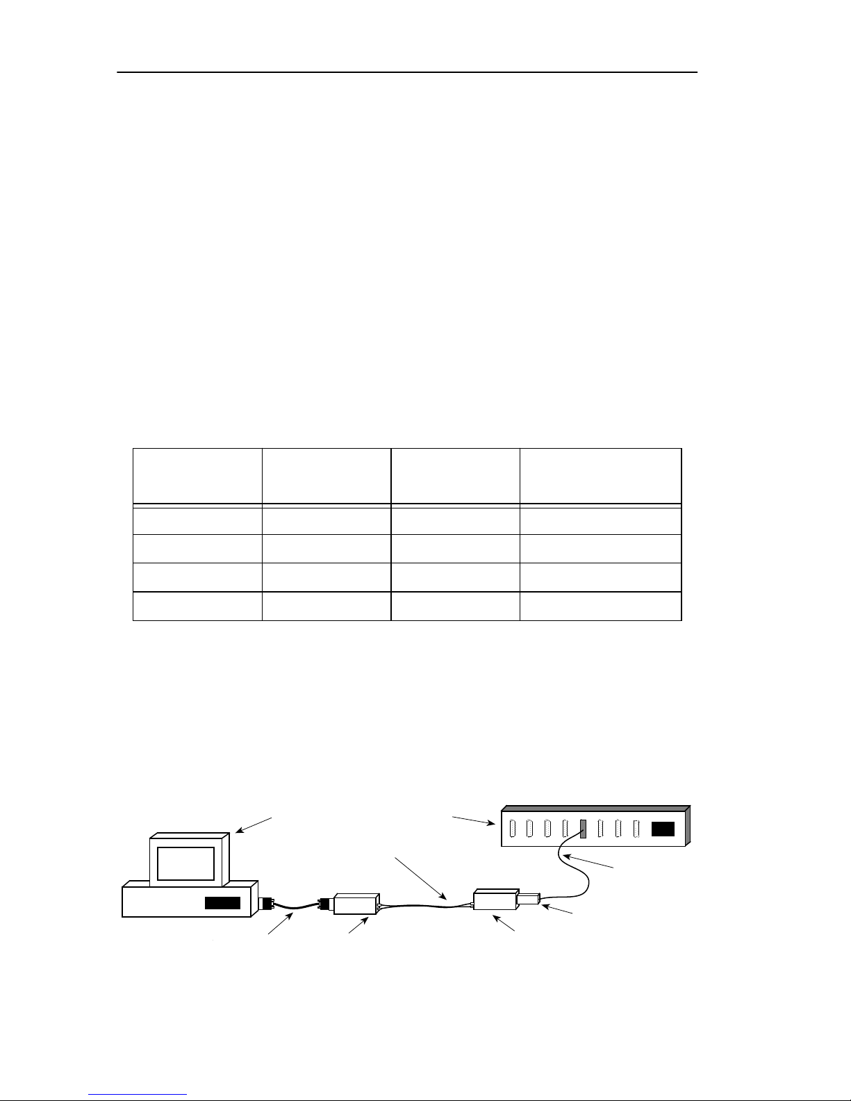
To connect an Unshielded Twisted Pair (UTP) segment from a token
ring concentrator to the TRFOT-3, you need to install a Type 3 media
filter such as the Cabletron Systems TRMF-2. Use the TRMF-2 at the
concentrator end of the connection as shown in Figure 2-1.
PC
Single Mode Fiber Cable
Concentrator
UTP Cable
DB9 STP Cable
Figure 2-1. UTP Cable Connections
Page 2-2
TRFOT-3
TRMF-2 Media Filter
TRFOT-3
Page 9

INSTALLATION REQUIREMENTS/SPECIFICATIONS
2.3 OPERATING SPECIFICATIONS
This section lists power supply requirements, safety and
environmental guidelines, and physical specifications for the
TRFOT-3. Cabletron Systems reserves the right to change these
specifications at any time without notice.
POWER REQUIREMENTS
Input V oltage: 9-12 VDC
Input Current: 700 ma, Maximum
FIBER OPTIC TRANSMIT/RECEIVE SPECIFICATIONS
Transmit Power: -15.1 dBm
Receive Sensitivity: -32 dBm
Maximum Receive Power: -6.99 dBm
SAFETY AND ENVIRONMENTAL APPROVALS
This device meets FCC Class A, UL and VDE requirement for
emissions.
PHYSICAL
Dimensions: 2.875 H x 5.250 W x .875 D inches
(7.18 H x 13.12 W x 2.18 D centimeters)
Weight: .40 lbs
Page 2-3
Page 10
INSTALLING THE TRFOT-3
CHAPTER 3
INST ALLING THE TRFOT-3
This chapter outlines how to install the TRFOT-3 to your network.
Ensure that your network meets all the requirements listed in
Chapter 2,
installing and operating the TRFOT-3.
3.1 UNPACKING THE TRFOT-3
Unpack the TRFOT-3 as follows:
1. Carefully remove the TRFOT-3 from the shipping box.
Installation Requirements/Specifications
, before
2. Remove the TRFOT-3 from its protective plastic bag.
3. Visually inspect the TRFOT-3. If there are any signs of damage,
contact Cabletron Systems Technical Support immediately.
3.2 SETTING THE CONFIGURATION SWITCHES
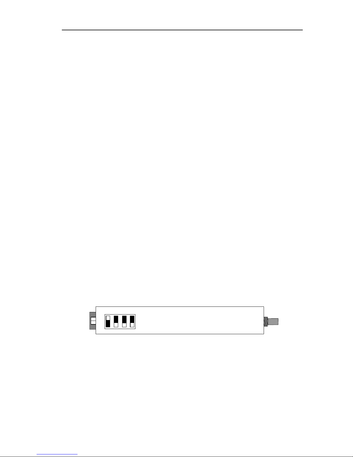
Figure 3-1 shows the location of the TRFOT-3’s four configuration
switches. Cabletron sets the switches for Station applications. If you
need to change the switches for other applications, follow steps 1-3.
A B C D
OFF
ON
Figure 3-1. TRFOT-3 Configuration Switches
1. Disconnect the TRFOT-3 from the network and remove the power.
2. Set the switches for the desired application (refer to Table 3-1).
3. Reconnect the TRFOT-3 to the network, then re-apply the power.
Page 3-1
Page 11

INSTALLING THE TRFOT-3
T able 3-1 provides a quick reference for the switch settings for Station,
Lobe Concentrator/Trunk Coupling Unit (TCU), Ring In (RI), and
Ring Out (RO) applications. A description of each switch is also listed
below.
Table 3-1. Switch Settings
Switch Station Lobe
Ring In Ring Out
(TCU)
A On Off On Off
B Off Off On On
C Off Off On - Disables phantom drive.
Off - Enables phantom drive (for
use with Cabletron proprietary devices only).
D Off Off On - Cabletron proprietary devices.
Off - 802.5J compatible device.
Switch A
This switch selects Station/RI or Lobe/RO applications for the
TRFOT-3’s copper connector. Select ON to attach the TRFOT-3’s
copper connector to a Station adapter or Ring In port. Select OFF to
connect the copper connector to a concentrator lobe port or Ring Out
port.
Switch B
This switch selects RI/RO or Station/Lobe applications for the
TRFOT-3. Select ON for RI/RO applications. Select OFF for Station/
Lobe applications.
Switch C
This switch enables/disables the phantom drive for RI/RO applications
with other Cabletron products. Select ON to disable the phantom
drive. Select OFF to enable the phantom drive.
Switch D
This switch selects modes on the TRFOT-3’s fiber optic connector.
Select ON to attach the TRFOT-3’s fiber optic connector to a Cabletron
fiber RI/RO port, for example the TRRMIM-A/2A/4A. Select OFF to
attach the fiber optic connector to an IEEE 802.5J compatible RI/RO
Page 3-2
Page 12
INSTALLING THE TRFOT-3
port.
3.3 ATTACHING THE TOKEN RING CABLE TO A
CONCENTRATOR
To attach the TRFOT-3 to a token ring concentrator that supports
Shielded Twisted Pair (STP), use the DB9 to DB9 cable supplied with
the unit. If you want to attach the TRFOT-3 to a concentrator that
does not have a DB9 connector, you need an adapter cable. Cabletron
offers cables that adapt to RJ45 and MIC style connectors. The
maximum supported length for the copper cable is 10 feet.
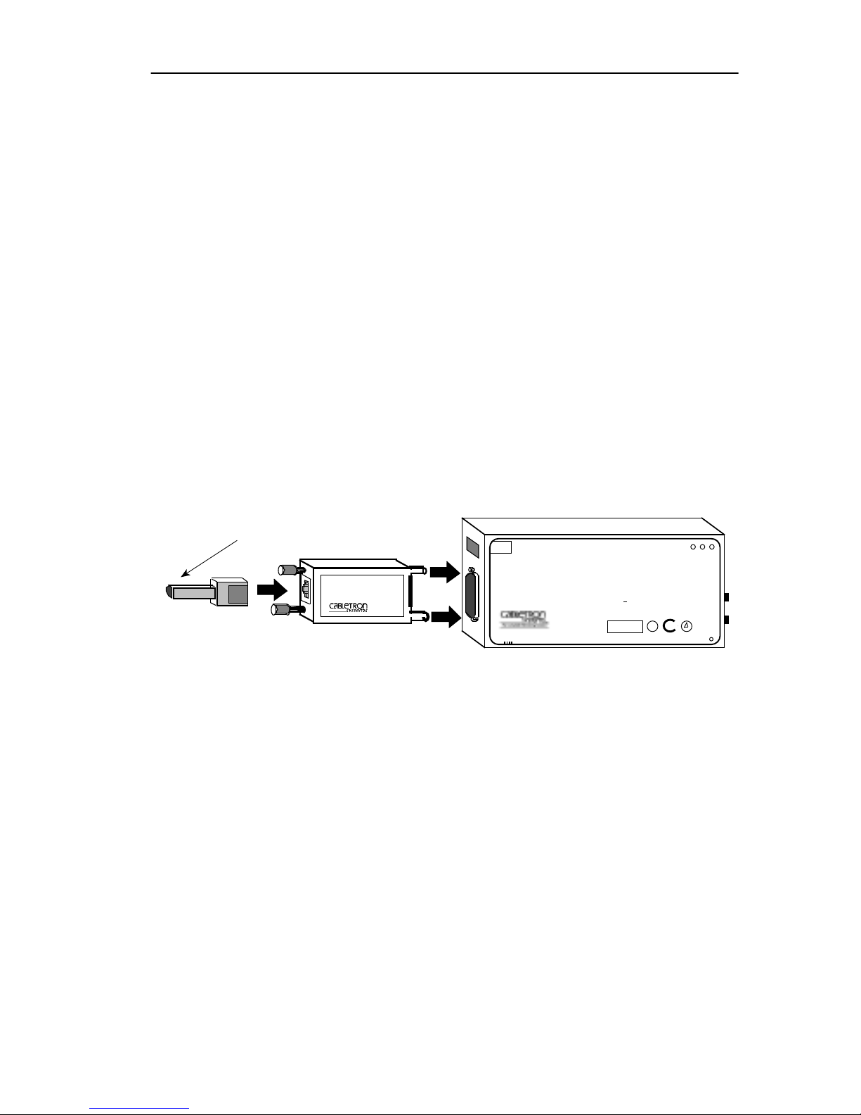
To attach the TRFOT-3 to a token ring concentrator that supports
Unshielded Twisted Pair (UTP) cable, you need to install a Type 3
media filter such as the Cabletron Systems TRMF-2. Figure 3-2 shows
how to attach a UTP segment to the TRFOT-3 using the TRMF-2.
UTP Segment
TOKEN RING
MEDIA FILTER
TRMF-2
POWER
TRFOT-3
INPUT
802.5 TOKEN RING COPPER TO SINGLE MODE
FIBER OPTIC TRANSCEIVER
A B C D
®
WITH
LANVIEW
THIS DEVICE COMPLIES WITH PART 15 OF THE FCC RULES.
OPERATION IS SUBJECT TO THE FOLLOWING TWO CONDITIONS:
(1) THIS DEVICE MAY NOT CAUSE HARMFUL INTERFERENCE, AND
(2) THIS DEVICE MUST ACCEPT ANY INTERFERENCE RECEIVED,
INCLUDING INTERFERENCE THAT MAY CAUSE UNDESIRED OPERATION.
POWER REQUIRED: 9-12V ----,700mA MAX
DATA CAPABILITY: 4/16Mb/s AUTO SENSING
SN
C
P
F
U
W
O
R
LNK
TX
U
L
RX
SA
Figure 3-2. Attaching a UTP Segment to the TRFOT-3
3.4 ATTACHING FIBER OPTIC CABLES
Note
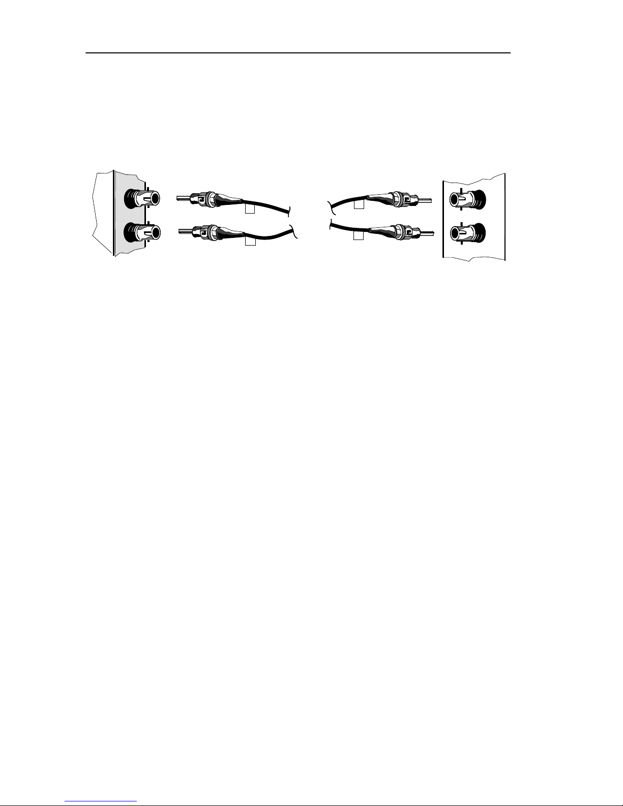
: The fiber optic cables must be crossed over (i.e. TX on one end to
RX on the other end) when connected. To facilitate hookup, label the
fiber optic strands 1 and 2.
To connect a fiber optic link segment to a TRFOT-3:
1. Remove the protective plastic covers from the fiber optic ports on
the applicable port on the module and from the ends of the
connectors on each fiber strand.
Page 3-3
Page 13
INSTALLING THE TRFOT-3
2. Attach the fiber labeled 1 to the applicable receive port, labeled RX,
on the TRFOT-3. See Figure 3-3.
TX
RX
TRFOT-3
2
1
1
2
TRFMIM
TX
RX
Figure 3-3. Connecting Fiber Cables
3. Attach the fiber labeled 2 to the applicable transmit port, labeled
TX
, on the TRFOT-3.
4. At the other end of the fiber optic cable, attach the fiber labeled 1
to the transmit port of the device.
5. Attach the fiber optic cable labeled 2 to the receive port of the
device.
6. Check that the
FO
Link LED is lit. If the LED is not lit, perform
each of the following steps until it is:
Note
: Perform the following steps only if the device attached to the
TRFOT-3 is a Cabletron device, for example the TRFMIM-32/36/38. If
you attach a non-Cabletron device to the TRFOT-3, the
FO
Link LED
may not light, even though a good link may exist.
a. Check that the power is turned on for the device at the other
end of the link.
b. Verify that the fiber strands are properly “crossed-over”
between the applicable port on the module and the fiber optic
device at the other end of the fiber optic link segment.
Page 3-4
Page 14
INSTALLING THE TRFOT-3
c. Reset the TRFOT-3 by cycling the power.
d. Verify that the fiber connection meets the dB loss specifications
outlined in Fiber Optic Network Requirements.
Note
: If after proper insertion to the ring, one of the fiber cables is
disconnected, the other fiber cable should also be disconnected before
reconnecting. The TX cable must be reconnected first on the station
TRFOT-3, then the RX cable.
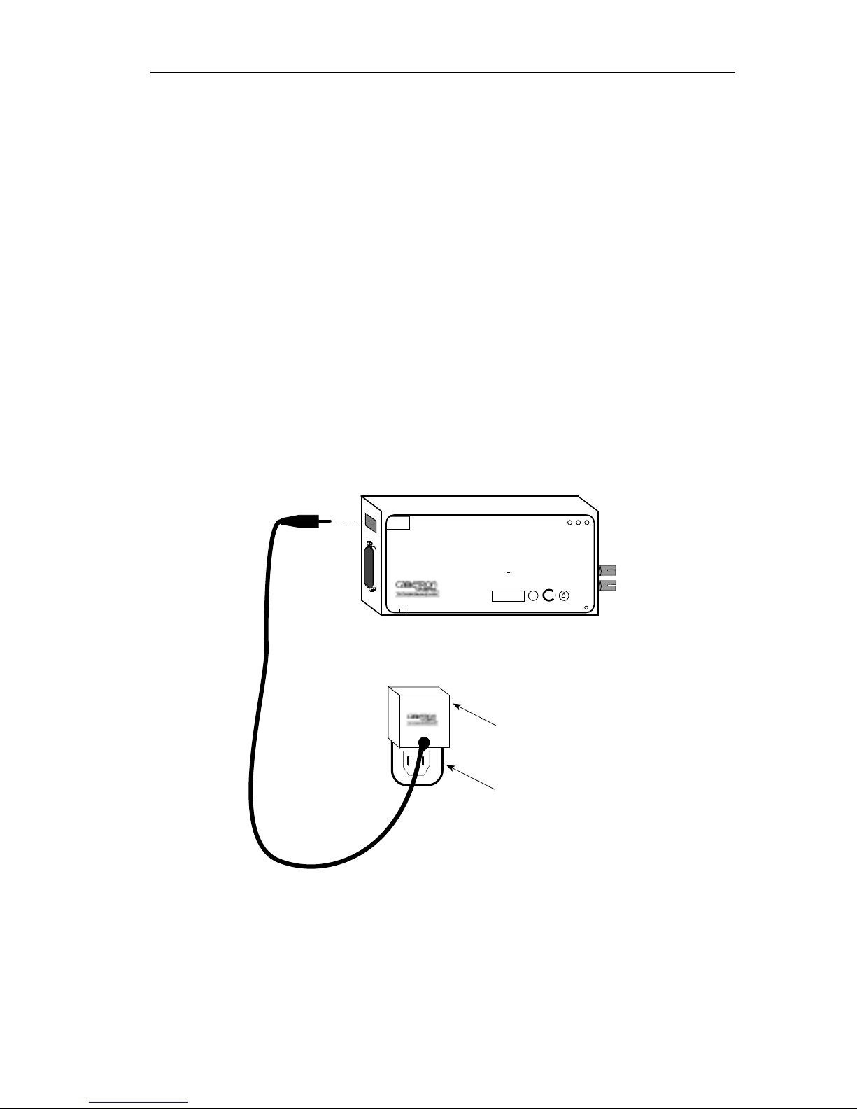
3.5 CONNECTING POWER
The TRFOT-3 is equipped with an external power supply. Plug the
power supply connector into the
Power Input
port on the TRFOT-3,
then plug the power supply into a standard wall outlet.
POWER
TRFOT-3
INPUT
802.5 TOKEN RING COPPER TO SINGLE MODE
FIBER OPTIC TRANSCEIVER
A B C D
®
WITH
LANVIEW
THIS DEVICE COMPLIES WITH PART 15 OF THE FCC RULES.
OPERATION IS SUBJECT TO THE FOLLOWING TWO CONDITIONS:
(1) THIS DEVICE MAY NOT CAUSE HARMFUL INTERFERENCE, AND
(2) THIS DEVICE MUST ACCEPT ANY INTERFERENCE RECEIVED,
INCLUDING INTERFERENCE THAT MAY CAUSE UNDESIRED OPERATION.
POWER REQUIRED: 9-12V ----,700mA MAX
DATA CAPABILITY: 4/16Mb/s AUTO SENSING
SN
U
L
C
P
F
U
W
O
R
LNK
TX
RX
SA
Figure 3-4. Attaching the Power Supply
Power Supply
Wall Outlet
Page 3-5
Page 15
INSTALLING THE TRFOT-3
3.6 MOUNTING THE TRFOT-3
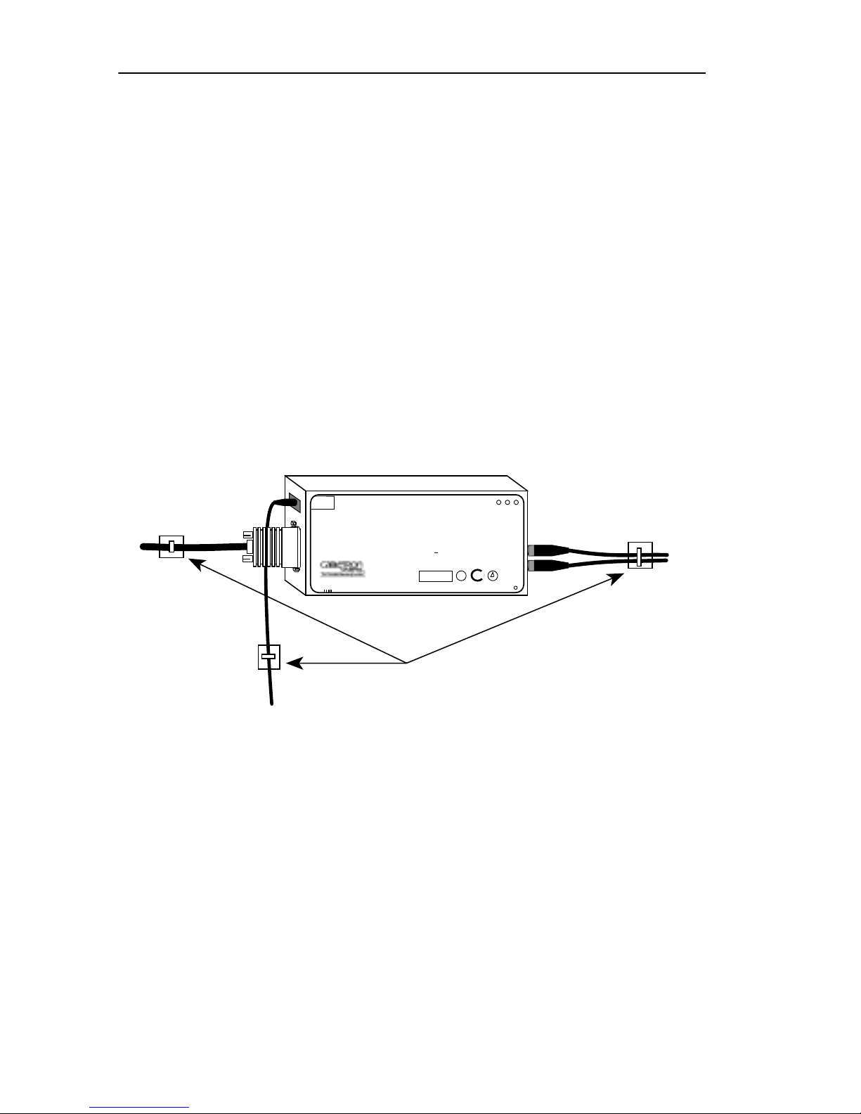
Use the cable mounts, Tie Wraps, and Velcro Strips included with the
TRFOT-3 to wall-mount the unit.
1. Remove the tape from the adhesive backing on the Velcro strips.
2. Place one Velcro half on the TRFOT-3 and the other half on the
mounting surface.
3. Press firmly on each Velcro strip, then press the TRFOT-3 onto the
mounting surface.
4. Secure the TRFOT-3’s cables to the wall using the adhesive backed
cable mounts and tie wraps as shown in Figure 3-5.
POWER
TRFOT-3
INPUT
802.5 TOKEN RING COPPER TO SINGLE MODE
FIBER OPTIC TRANSCEIVER
A B C D
®
WITH
LANVIEW
THIS DEVICE COMPLIES WITH PART 15 OF THE FCC RULES.
OPERATION IS SUBJECT TO THE FOLLOWING TWO CONDITIONS:
(1) THIS DEVICE MAY NOT CAUSE HARMFUL INTERFERENCE, AND
(2) THIS DEVICE MUST ACCEPT ANY INTERFERENCE RECEIVED,
INCLUDING INTERFERENCE THAT MAY CAUSE UNDESIRED OPERATION.
POWER REQUIRED: 9-12V ----,700mA MAX
DATA CAPABILITY: 4/16Mb/s AUTO SENSING
SN
U
L
C
P
F
U
W
O
R
LNK
TX
RX
SA
Cable Mounts and Tie Wraps
Figure 3-5. Mounting the TRFOT-3
Page 3-6
Page 16

INSTALLING THE TRFOT-3
3.7 USING LANVIEW LEDS
The front panel LEDs help you diagnose power and link problems
associated with the TRFOT-3. Table 3-2 explains each LED.
Table 3-2. LANVIEW LEDS
LED LED Color Definition
PWR
CU Green
Green
Off
Flashing Green
TRFOT-3 is receiving power.
TRFOT-3 is not receiving power.
Phantom detected/valid copper link.
Phantom detected/valid copper link, no
data present.
Red
FO Green
Phantom not detected/No Copper link.
Fiber optic link is correctly connected to
RX port and signal is present.
Red
Fiber optic link is not connected
correctly or signal is not present.
CU
If the
LED is red, follow these steps until it changes to green:
1. Verify that the proper adapter card software is loaded on the host
machine.
2. Check the
FO
as detailed in Section 3.4.
3. Check the copper cable connecting the TRFOT-3 to the device.
Verify that it is installed correctly, see Section 3.3.
4. Reset the TRFOT-3 by cycling power.
5. Reboot the PC containing the station adapter card and reload the
adapter card software.
LED. If it is not lit, check the fiber optic connections
Page 3-7
 Loading...