

Page 1
Title Page
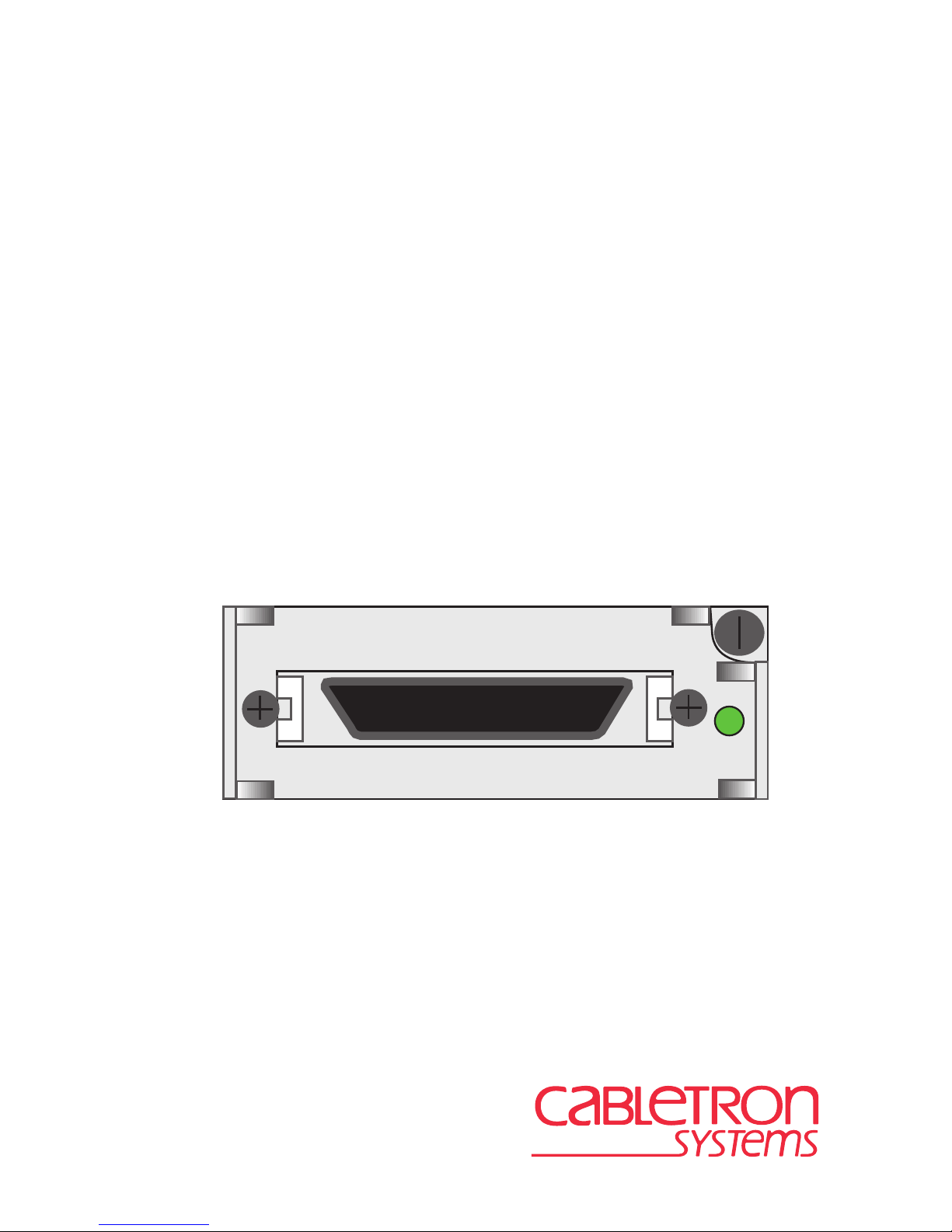
SWPIM-SY
Installation Guide
LNK
SWPIM-SY
9033001-02
Page 2

Page 3

Only qualified personnel should perform installation
procedures.
NOTICE
Cabletron Systems reserves the right to make changes in specifications and other information
contained in this document without prior notice. The reader should in all cases consult Cabletron
Systems to determine whether any such changes have been made.
The hardware, firmware, or software described in this manual is subject to change without notice.
IN NO EVENT SHALL CABLETRON SYSTEMS BE LIABLE FOR ANY INCIDENTAL,
INDIRECT, SPECIAL, OR CONSEQUENTIAL DAMAGES WHATSOEVER (INCLUDING BUT
NOT LIMITED TO LOST PROFITS) ARISING OUT OF OR RELATED TO THIS MANUAL OR
THE INFORMATION CONTAINED IN IT, EVEN IF CABLETRON SYSTEMS HAS BEEN
ADVISED OF, KNOWN, OR SHOULD HAVE KNOWN, THE POSSIBILITY OF SUCH
DAMAGES.
Cabletron Systems, Inc.
35 Industrial Way
Rochester, NH 03867
1999 by Cabletron Systems, Inc.
All Rights Reserved
Printed in the United States of America
Order Number: 9033001-02 October 1999
Cabletron Systems, SPECTRUM
trademark of Cabletron Systems, Inc.
All other product names mentioned in this manual may be trademarks or registered trademarks of
their respective companies.
, and
LANVIEW
are registered trademarks and
SmartSwitch
is a
FCC NOTICE
This device complies with Part 15 of the FCC rules. Operation is subject to the following two
conditions: (1) this device may not cause harmful interference, and (2) this device must accept any
interference received, including interference that may cause undesired operation.
NOTE:
device, pursuant to Part 15 of the FCC rules. These limits are designed to provide reasonable
protection against harmful interference when the equipment is operated in a commercial environment.
This equipment uses, generates, and can radiate radio frequency energy and if not installed in
accordance with the operator’s manual, may cause harmful interference to radio communications.
Operation of this equipment in a residential area is likely to cause interference in which case the user
will be required to correct the interference at his own expense.
WARNING:
party responsible for compliance could void the user’s authority to operate the equipment.
This equipment has been tested and found to comply with the limits for a Class A digital
Changes or modifications made to this device which are not expressly approv ed by the
SWPIM-SY Installation Guide i
Page 4

Notice
INDUSTRY CANADA NOTICE
This digital apparatus does not exceed the Class A limits for radio noise emissions from digital
apparatus set out in the Radio Interference Regulations of the Canadian Department of
Communications.
Le présent appareil numérique n’émet pas de bruits radioélectriques dépassant les limites applicables
aux appareils numériques de la class A prescrites dans le Règlement sur le brouillage radioélectrique
édicté par le ministère des Communications du Canada.
NOTICE:
equipment meets telecommunications network protective, operational and safety requirements as
prescribed in the appropriate Terminal Equipment Technical Requirements documents (s). The
department does not guarantee the equipment will operate to the user’s satisfaction.
Before installing this equipment, users should ensure that it is permissible to be connected to the
facilities of the local telecommunications company. The equipment must also be installed using an
acceptable method of connection. The customer should be aware that compliance with the above
conditions may not prevent degradation of service in some situations.
Repairs to certified equipment should be coordinated by a representative designated by the supplier.
Any repairs or alterations made by the user to this equipment, or equipment malfunctions, may give
the telecommunications company cause to request the user to disconnect the equipment.
Users should ensure for their own protection that the electrical ground connections of the power
utility , telephone lines and internal metallic water pipe system, if present, are connected together . This
precaution may be particularly important in rural areas.
such connections themselves, but should contact the appropriate electric inspection authority, or
electrician, as appropriate.
NOTICE:
indication of the maximum number of terminals allowed to be connected to a telephone interface. The
termination on an interface may consist of any combination of devices subject only to the requirement
that the sum of the ringer equivalence Numbers of all the devices does not exceed 5.
The Industry Canada label identifies certified equipment. This certification means that the
Caution:
The Ringer Equivalence Number (REN) assigned to each terminal device provides an
Users should not attempt to make
VCCI NOTICE
This is a Class A product based on the standard of the Voluntary Control Council for Interference by
Information Technology Equipment (VCCI). If this equipment is used in a domestic environment,
radio disturbance may arise. When such trouble occurs, the user may be required to take corrective
actions.
ii SWPIM-SY Installation Guide
Page 5

Notice
CABLETRON SYSTEMS, INC.
PROGRAM LICENSE AGREEMENT
IMPORTANT: THIS LICENSE APPLIES FOR USE OF PR ODUCT IN THE FOLLOWING
GEOGRAPHICAL REGIONS:
CANADA
MEXICO
CENTRAL AMERICA
SOUTH AMERICA
BEFORE OPENING OR UTILIZING THE ENCLOSED PRODUCT,
CAREFULLY READ THIS LICENSE AGREEMENT.
This document is an agreement (“Agreement”) between You, the end user, and Cabletron
Systems, Inc. (“Cabletron”) that sets forth your rights and obligations with respect to the Cabletron
software program (“Program”) in the package. The Program may be contained in firmware, chips or
other media. UTILIZING THE ENCLOSED PRODUCT, YOU ARE AGREEING TO BECOME
BOUND BY THE TERMS OF THIS AGREEMENT, WHICH INCLUDES THE LICENSE AND
THE LIMITATION OF WARRANTY AND DISCLAIMER OF LIABILITY. IF YOU DO NOT
AGREE TO THE TERMS OF THIS AGREEMENT, RETURN THE UNOPENED PRODUCT TO
CABLETRON OR YOUR DEALER, IF ANY, WITHIN TEN (10) DAYS FOLLO WING THE DATE
OF RECEIPT FOR A FULL REFUND.
IF YOU HAVE ANY QUESTIONS ABOUT THIS AGREEMENT, CONTACT CABLETRON
SYSTEMS +1-603-332-9400. Attn: Legal Department.
1. LICENSE.
package subject to the terms and conditions of this License Agreement.
You may not copy, reproduce or transmit any part of the Program except as permitted by the
Copyright Act of the United States or as authorized in writing by Cabletron.
2. OTHER RESTRICTIONS.
Program.
3. APPLICABLE LAW.
laws and in the state and federal courts of New Hampshire. You accept the personal jurisdiction and
venue of the New Hampshire courts.
4. EXPORT REQUIREMENTS.
regulation by agencies of the U.S. Government, including the U.S. Department of Commerce, which
prohibit export or diversion of certain technical products to certain countries, unless a license to export
the product is obtained from the U.S. Government or an exception from obtaining such license may be
relied upon by the exporting party.
If the Program is exported from the United States pursuant to the License Exception CIV under
the U.S. Export Administration Regulations, You agree that You are a civil end user of the Program
and agree that You will use the Program for civil end uses only and not for military purposes.
You have the right to use only the one (1) copy of the Program provided in this
You may not reverse engineer, decompile, or disassemble the
This License Agreement shall be interpreted and governed under the
You understand that Cabletron and its Affiliates are subject to
SWPIM-SY Installation Guide iii
Page 6

Notice
If the Program is exported from the United States pursuant to the License Exception TSR under
the U.S. Export Administration Regulations, in addition to the restriction on transfer set forth in
Sections 1 or 2 of this Agreement, You agree not to (i) reexport or release the Program, the source
code for the Program or technology to a national of a country in Country Groups D:1 or E:2 (Albania,
Armenia, Azerbaijan, Belarus, Bulgaria, Cambodia, Cuba, Estonia, Georgia, Iraq, Kazakhstan,
Kyrgyzstan, Laos, Latvia, Libya, Lithuania, Moldova, North Korea, the People’s Republic of China,
Romania, Russia, Rwanda, Tajikistan, Turkmenistan, Ukraine, Uzbekistan, Vietnam, or such other
countries as may be designated by the United States Government), (ii) export to Country Groups D:1
or E:2 (as defined herein) the direct product of the Program or the technology, if such foreign
produced direct product is subject to national security controls as identified on the U.S. Commerce
Control List, or (iii) if the direct product of the technology is a complete plant o r any major
component of a plant, export to Country Groups D:1 or E:2 the direct product of the plant or a major
component thereof, if such foreign produced direct product is subject to national security controls as
identified on the U.S. Commerce Control List or is subject to State Department controls under the
U.S. Munitions List.
5. UNITED STATES GOVERNMENT RESTRICTED RIGHTS.
was developed solely at private expense; (ii) contains “restricted computer software” submitted with
restricted rights in accordance with section 52.227-19 (a) through (d) of the Commercial Computer
Software-Restricted Rights Clause and its successors, and (iii) in all respects is proprietary data
belonging to Cabletron and/or its suppliers. For Department of Defense units, the Product is considered
commercial computer software in accordance with DFARS section 227.7202-3 and its successors, and
use, duplication, or disclosure by the Government is subject to restrictions set forth herein.
6. EXCLUSION OF WARRANTY.
writing, Cabletron makes no warranty, expressed or implied, concerning the Program (including its
documentation and media).
CABLETRON DISCLAIMS ALL WARRANTIES, OTHER THAN THOSE SUPPLIED TO
YOU BY CABLETRON IN WRITING, EITHER EXPRESS OR IMPLIED, INCLUDING BUT
NOT LIMITED TO IMPLIED WARRANTIES OF MERCHANTABILITY AND FITNESS FOR A
PARTICULAR PURPOSE, WITH RESPECT TO THE PROGRAM, THE ACCOMPANYING
WRITTEN MATERIALS, AND ANY A CCOMPANYING HARDWARE.
7. NO LIABILITY FOR CONSEQUENTIAL DAMAGES.
CABLETRON OR ITS SUPPLIERS BE LIABLE FOR ANY DAMAGES WHATSOEVER
(INCLUDING, WITHOUT LIMITATION, DAMAGES FOR LOSS OF BUSINESS, PROFITS,
BUSINESS INTERRUPTION, LOSS OF BUSINESS INFORMATION, SPECIAL, INCIDENTAL,
CONSEQUENTIAL, OR RELIANCE DAMAGES, OR OTHER LOSS) ARISING OUT OF THE
USE OR INABILITY TO USE THIS CABLETRON PRODUCT, EVEN IF CABLETRON HAS
BEEN ADVISED OF THE POSSIBILITY OF SUCH DAMAGES. BECAUSE SOME STATES DO
NOT ALLOW THE EXCLUSION OR LIMITATION OF LIABILITY FOR CONSEQUENTIAL OR
INCIDENTAL DAMAGES, OR IN THE DURATION OR LIMITATION OF IMPLIED
WARRANTIES IN SOME INSTANCES, THE ABOVE LIMITATION AND EXCLUSIONS MAY
NOT APPLY TO YOU.
Except as may be specifically provided by Cabletron in
IN NO EVENT SHALL
The enclosed Product (i)
iv SWPIM-SY Installation Guide
Page 7

Notice
CABLETRON SYSTEMS SALES AND SERVICE, INC.
PROGRAM LICENSE AGREEMENT
IMPORTANT: THIS LICENSE APPLIES FOR USE OF PRODUCT IN THE UNITED
STATES OF AMERICA AND BY UNITED STATES OF AMERICA
GOVERNMENT END USERS.
BEFORE OPENING OR UTILIZING THE ENCLOSED PRODUCT,
CAREFULLY READ THIS LICENSE AGREEMENT.
This document is an agreement (“Agreement”) between You, the end user, and Cabletron Systems
Sales and Service, Inc. (“Cabletron”) that sets forth your rights and obligations with respect to the
Cabletron software program (“Program”) in the package. The Program may be contained in firmware,
chips or other media. UTILIZING THE ENCLOSED PRODUCT, YOU ARE AGREEING TO
BECOME BOUND BY THE TERMS OF THIS AGREEMENT, WHICH INCLUDES THE
LICENSE AND THE LIMITATION OF WARRANTY AND DISCLAIMER OF LIABILITY. IF
YOU DO NOT AGREE TO THE TERMS OF THIS AGREEMENT, RETURN THE UNOPENED
PRODUCT TO CABLETRON OR YOUR DEALER, IF ANY, WITHIN TEN (10) DAYS
FOLLOWING THE DATE OF RECEIPT FOR A FULL REFUND.
IF YOU HAVE ANY QUESTIONS ABOUT THIS AGREEMENT, CONTACT CABLETRON
SYSTEMS +1-603-332-9400. Attn: Legal Department.
1. LICENSE.
package subject to the terms and conditions of this License Agreement.
You may not copy, reproduce or transmit any part of the Program except as permitted by the
Copyright Act of the United States or as authorized in writing by Cabletron.
2. OTHER RESTRICTIONS.
Program.
3. APPLICABLE LAW.
laws and in the state and federal courts of New Hampshire. You accept the personal jurisdiction and
venue of the New Hampshire courts.
4. EXPORT REQUIREMENTS.
regulation by agencies of the U.S. Government, including the U.S. Department of Commerce, which
prohibit export or diversion of certain technical products to certain countries, unless a license to export
the product is obtained from the U.S. Government or an exception from obtaining such license may be
relied upon by the exporting party.
If the Program is exported from the United States pursuant to the License Exception CIV under
the U.S. Export Administration Regulations, You agree that You are a civil end user of the Program
and agree that You will use the Program for civil end uses only and not for military purposes.
You have the right to use only the one (1) copy of the Program provided in this
You may not reverse engineer, decompile, or disassemble the
This License Agreement shall be interpreted and governed under the
You understand that Cabletron and its Affiliates are subject to
SWPIM-SY Installation Guide v
Page 8

Notice
If the Program is exported from the United States pursuant to the License Exception TSR under
the U.S. Export Administration Regulations, in addition to the restriction on transfer set forth in
Sections 1 or 2 of this Agreement, You agree not to (i) reexport or release the Program, the source
code for the Program or technology to a national of a country in Country Groups D:1 or E:2 (Albania,
Armenia, Azerbaijan, Belarus, Bulgaria, Cambodia, Cuba, Estonia, Georgia, Iraq, Kazakhstan,
Kyrgyzstan, Laos, Latvia, Libya, Lithuania, Moldova, North Korea, the People’s Republic of China,
Romania, Russia, Rwanda, Tajikistan, Turkmenistan, Ukraine, Uzbekistan, Vietnam, or such other
countries as may be designated by the United States Government), (ii) export to Country Groups D:1
or E:2 (as defined herein) the direct product of the Program or the technology, if such foreign
produced direct product is subject to national security controls as identified on the U.S. Commerce
Control List, or (iii) if the direct product of the technology is a complete plant o r any major
component of a plant, export to Country Groups D:1 or E:2 the direct product of the plant or a major
component thereof, if such foreign produced direct product is subject to national security controls as
identified on the U.S. Commerce Control List or is subject to State Department controls under the
U.S. Munitions List.
5. UNITED STATES GOVERNMENT RESTRICTED RIGHTS.
was developed solely at private expense; (ii) contains “restricted computer software” submitted with
restricted rights in accordance with section 52.227-19 (a) through (d) of the Commercial Computer
Software-Restricted Rights Clause and its successors, and (iii) in all respects is proprietary data
belonging to Cabletron and/or its suppliers. For Department of Defense units, the Product is considered
commercial computer software in accordance with DFARS section 227.7202-3 and its successors, and
use, duplication, or disclosure by the Government is subject to restrictions set forth herein.
6. EXCLUSION OF WARRANTY.
writing, Cabletron makes no warranty, expressed or implied, concerning the Program (including its
documentation and media).
CABLETRON DISCLAIMS ALL WARRANTIES, OTHER THAN THOSE SUPPLIED TO
YOU BY CABLETRON IN WRITING, EITHER EXPRESS OR IMPLIED, INCLUDING BUT
NOT LIMITED TO IMPLIED WARRANTIES OF MERCHANTABILITY AND FITNESS FOR A
PARTICULAR PURPOSE, WITH RESPECT TO THE PROGRAM, THE ACCOMPANYING
WRITTEN MATERIALS, AND ANY A CCOMPANYING HARDWARE.
7. NO LIABILITY FOR CONSEQUENTIAL DAMAGES.
CABLETRON OR ITS SUPPLIERS BE LIABLE FOR ANY DAMAGES WHATSOEVER
(INCLUDING, WITHOUT LIMITATION, DAMAGES FOR LOSS OF BUSINESS, PROFITS,
BUSINESS INTERRUPTION, LOSS OF BUSINESS INFORMATION, SPECIAL, INCIDENTAL,
CONSEQUENTIAL, OR RELIANCE DAMAGES, OR OTHER LOSS) ARISING OUT OF THE
USE OR INABILITY TO USE THIS CABLETRON PRODUCT, EVEN IF CABLETRON HAS
BEEN ADVISED OF THE POSSIBILITY OF SUCH DAMAGES. BECAUSE SOME STATES DO
NOT ALLOW THE EXCLUSION OR LIMITATION OF LIABILITY FOR CONSEQUENTIAL OR
INCIDENTAL DAMAGES, OR IN THE DURATION OR LIMITATION OF IMPLIED
WARRANTIES IN SOME INSTANCES, THE ABOVE LIMITATION AND EXCLUSIONS MAY
NOT APPLY TO YOU.
Except as may be specifically provided by Cabletron in
IN NO EVENT SHALL
The enclosed Product (i)
vi SWPIM-SY Installation Guide
Page 9

Notice
CABLETRON SYSTEMS LIMITED
PROGRAM LICENSE AGREEMENT
IMPORTANT: THIS LICENSE APPLIES FOR THE USE OF THE PRODUCT IN THE
FOLLOWING GEOGRAPHICAL REGIONS:
EUROPE
MIDDLE EAST
AFRICA
ASIA
AUSTRALIA
PACIFIC RIM
BEFORE OPENING OR UTILIZING THE ENCLOSED PRODUCT,
CAREFULLY READ THIS LICENSE AGREEMENT.
This document is an agreement (“Agreement”) between You, the end user, and Cabletron
Systems Limited (“Cabletron”) that sets forth your rights and obligations with respect to the
Cabletron software program (“Program”) in the package. The Program may be contained in firmware,
chips or other media. UTILIZING THE ENCLOSED PRODUCT, YOU ARE AGREEING TO
BECOME BOUND BY THE TERMS OF THIS AGREEMENT, WHICH INCLUDES THE
LICENSE AND THE LIMITATION OF WARRANTY AND DISCLAIMER OF LIABILITY. IF
YOU DO NOT AGREE TO THE TERMS OF THIS AGREEMENT, RETURN THE UNOPENED
PRODUCT TO CABLETRON OR YOUR DEALER, IF ANY, WITHIN TEN (10) DAYS
FOLLOWING THE DATE OF RECEIPT FOR A FULL REFUND.
IF YOU HAVE ANY QUESTIONS ABOUT THIS AGREEMENT, CONTACT CABLETRON
SYSTEMS +1-603-332-9400. Attn: Legal Department.
1. LICENSE.
package subject to the terms and conditions of this License Agreement.
You may not copy, reproduce or transmit any part of the Program except as permitted by the
Copyright Act of the United States or as authorized in writing by Cabletron.
2. OTHER RESTRICTIONS.
Program.
3. APPLICABLE LAW.
law. The English courts shall have exclusive jurisdiction in the event of any disputes.
4. EXPORT REQUIREMENTS.
regulation by agencies of the U.S. Government, including the U.S. Department of Commerce, which
prohibit export or diversion of certain technical products to certain countries, unless a license to export
the product is obtained from the U.S. Government or an exception from obtaining such license may be
relied upon by the exporting party.
If the Program is exported from the United States pursuant to the License Exception CIV under
the U.S. Export Administration Regulations, You agree that You are a civil end user of the Program
and agree that You will use the Program for civil end uses only and not for military purposes.
You have the right to use only the one (1) copy of the Program provided in this
You may not reverse engineer, decompile, or disassemble the
This License Agreement shall be governed in accordance with English
You understand that Cabletron and its Affiliates are subject to
SWPIM-SY Installation Guide vii
Page 10

Notice
If the Program is exported from the United States pursuant to the License Exception TSR under
the U.S. Export Administration Regulations, in addition to the restriction on transfer set forth in
Sections 1 or 2 of this Agreement, You agree not to (i) reexport or release the Program, the source
code for the Program or technology to a national of a country in Country Groups D:1 or E:2 (Albania,
Armenia, Azerbaijan, Belarus, Bulgaria, Cambodia, Cuba, Estonia, Georgia, Iraq, Kazakhstan,
Kyrgyzstan, Laos, Latvia, Libya, Lithuania, Moldova, North Korea, the People’s Republic of China,
Romania, Russia, Rwanda, Tajikistan, Turkmenistan, Ukraine, Uzbekistan, Vietnam, or such other
countries as may be designated by the United States Government), (ii) export to Country Groups D:1
or E:2 (as defined herein) the direct product of the Program or the technology, if such foreign
produced direct product is subject to national security controls as identified on the U.S. Commerce
Control List, or (iii) if the direct product of the technology is a complete plant o r any major
component of a plant, export to Country Groups D:1 or E:2 the direct product of the plant or a major
component thereof, if such foreign produced direct product is subject to national security controls as
identified on the U.S. Commerce Control List or is subject to State Department controls under the
U.S. Munitions List.
5. UNITED STATES GOVERNMENT RESTRICTED RIGHTS.
was developed solely at private expense; (ii) contains “restricted computer software” submitted with
restricted rights in accordance with section 52.227-19 (a) through (d) of the Commercial Computer
Software-Restricted Rights Clause and its successors, and (iii) in all respects is proprietary data
belonging to Cabletron and/or its suppliers. For Department of Defense units, the Product is considered
commercial computer software in accordance with DFARS section 227.7202-3 and its successors, and
use, duplication, or disclosure by the Government is subject to restrictions set forth herein.
6. EXCLUSION OF WARRANTY.
writing, Cabletron makes no warranty, expressed or implied, concerning the Program (including its
documentation and media).
CABLETRON DISCLAIMS ALL WARRANTIES, OTHER THAN THOSE SUPPLIED TO
YOU BY CABLETRON IN WRITING, EITHER EXPRESS OR IMPLIED, INCLUDING BUT
NOT LIMITED TO IMPLIED WARRANTIES OF MERCHANTABILITY AND FITNESS FOR A
PARTICULAR PURPOSE, WITH RESPECT TO THE PROGRAM, THE ACCOMPANYING
WRITTEN MATERIALS, AND ANY A CCOMPANYING HARDWARE.
7.
NO LIABILITY FOR CONSEQUENTIAL DAMAGES. IN NO EVENT SHALL
CABLETRON OR ITS SUPPLIERS BE LIABLE FOR ANY DAMAGES WHATSOEVER
(INCLUDING, WITHOUT LIMITATION, DAMAGES FOR LOSS OF BUSINESS, PROFITS,
BUSINESS INTERRUPTION, LOSS OF BUSINESS INFORMATION, SPECIAL, INCIDENTAL,
CONSEQUENTIAL, OR RELIANCE DAMAGES, OR OTHER LOSS) ARISING OUT OF THE
USE OR INABILITY TO USE THIS CABLETRON PRODUCT, EVEN IF CABLETRON HAS
BEEN ADVISED OF THE POSSIBILITY OF SUCH DAMAGES. BECAUSE SOME STATES DO
NOT ALLOW THE EXCLUSION OR LIMITATION OF LIABILITY FOR CONSEQUENTIAL OR
INCIDENTAL DAMAGES, OR IN THE DURATION OR LIMITATION OF IMPLIED
WARRANTIES IN SOME INSTANCES, THE ABOVE LIMITATION AND EXCLUSIONS MAY
NOT APPLY TO YOU.
Except as may be specifically provided by Cabletron in
The enclosed Product (i)
viii SWPIM-SY Installation Guide
Page 11

DECLARATION OF CONFORMITY
Notice
Application of Council Directive(s):
Manufacturer’s Name:
Manufacturer’ s Address:
European Representative Name:
European Representative Address:
Conformance to Directive(s)/Product Standards:
Equipment Type/Environment:
89/336/EEC
73/23/EEC
Cabletron Systems, Inc.
35 Industrial Way
PO Box 5005
Rochester, NH 03867
Mr. J. Solari
Cabletron Systems Limited
Nexus House, Newbury Business Park
London Road, Newbury
Berkshire RG14 2PZ, England
EC Directive 89/336/EEC
EC Directive 73/23/EEC
EN 55022
EN 50082-1
EN 60950
Networking Equipment, for use in a
Commercial or Light
Environment.
Industrial
We the undersigned, hereby declare, under our sole responsibility, that the equipment packaged
with this notice conforms to the above directives.
Manufacturer Legal Representative in Europe
Mr. Ronald Fotino Mr. J. Solari
___________________________________ ___________________________________
Full Name Full Name
Compliance Engineering Manager Managing Director - E.M.E.A.
___________________________________ ___________________________________
Title Title
Rochester, NH, USA Newbury, Berkshire, England
___________________________________ ___________________________________
Location Location
SWPIM-SY Installation Guide ix
Page 12

Notice
x SWPIM-SY Installation Guide
Page 13

CONTENTS
INTRODUCTION
Using This Guide..........................................................................xiii
Structure of This Guide.................................................................xiii
SWPIM-SY Features....................................................................xiv
Related Manuals............................................................................xv
Document Conventions................................................................xvi
Getting Help.................................................................................xvii
CHAPTER 1 INSTALLATION
1.1 Unpacking the SWPIM-SY .......................................................... 1-1
1.2 Installing the SWPIM-SY.............................................................1-2
1.3 LANVIEW LED Indications..........................................................1-4
1.4 Connecting to the Network..........................................................1-4
1.5 Completing the Installation..........................................................1-5
APPENDIX A SPECIFICATIONS
A.1 Physical Properties......................................................................A-1
A.2 Network Interface ........................................................................A-1
A.3 Environmental Requirements......................................................A-3
A.4 Regulatory Compliance...............................................................A-3
APPENDIX B CABLES AND PINOUTS
B.1 Interface Cable Part Numbers.....................................................B-1
B.2 RS449 / DTE Cable.....................................................................B-2
B.3 CCITT V.35 / DTE Cable.............................................................B-4
B.4 RS232 / DTE CABLE..................................................................B-6
B.5 CCITT X.21 / DTE Cable.............................................................B-7
B.6 EIA-530 / DTE Cable...................................................................B-8
B.7 EIA-530A / DTE Cable..............................................................B-10
B.8 RS449/DCE Cable.....................................................................B-12
B.9 CCITT V.35 / DCE Cable...........................................................B-14
B.10 RS232 / DCE Cable...................................................................B-16
B.11 CCITT X.21 / DCE Cable...........................................................B-17
B.12 EIA-530 / DCE Cable.................................................................B-18
B.13 EIA-530A / DCE Cable..............................................................B-20
SWPIM-SY Installation Guide xi
Page 14

Contents
xii SWPIM-SY Installation Guide
Page 15

INTRODUCTION
Only qualified personnel should perform installation
procedures.
Welcome to the Cabletron Systems SWPIM-SY Installation Guide
. This
manual provides an introduction to the SWPIM-SY, lists features and
capabilities, details the cabling pinouts, and explains how to install the
SWPIM-SY.
The SWPIM-SY (Sliding WAN Physical Interface Module) provides six
different synchronous/asynchronous serial interface protocol connections
to external communications equipment (e.g., a multiplexer or CSU/DSU)
for a host platform designed to receive the SWPIM architecture.
The term “host platform” may be used to indicate the device or
NOTE
interface module, such as the SSR-600 or the HSIM-SSR-600,
into which the SWPIM-SY is installed.
USING THIS GUIDE
Read through this guide completely to understand the features and
capabilities of the SWPIM-SY.
A general working knowledge of WAN and Ethernet and IEEE 802.3 data
communications networks and their physical layer components is helpful
before using the SWPIM-SY.
STRUCTURE OF THIS GUIDE
This guide is organized as follows:
This
Introduction
this manual, lists technology and user’s guides that may help the user to
set up and manage the SWPIM-SY, and gives an overview of the
SWPIM-SY and its features, and information on how to get help from
Cabletron Systems.
Chapter 1,
into a host platform, and gives the LED indications.
SWPIM-SY Installation Guide xiii
Installation
provides preliminary information that will aid in using
, provides instructions on how to install the device
Page 16

Introduction
Appendix A,
Specifications
, contains information on functionality and
operating specifications, connector pinouts for the SWPIM-SY,
environmental requirements, and physical properties.
Appendix B,
Cables and Pinouts
, provides Cabletron Systems part
numbers and detailed connector and pinout information for the different
interface cables used with the SWPIM-SY.
SWPIM-SY FEATURES
The SWPIM-SY can be installed into any Cabletron Systems product that
supports the SWPIM architecture, such as the SSR-600, or the
HSIM-SSR-600.
The SWPIM-SY uses a 36-pin AMP female connector supporting the
following electrical signal interfaces:
•
EIA- 232-D
•
EIA- 449
•
V.35
•
X.21
•
EIA-530
•
EIA-530A
Refer to Appendix B for the Cabletron Systems part numbers and pin
assignments for these cables.
The interface network cable types are software detectable. The
SWPIM-SY detects the type of cable attached and whether it is DTE or
DCE.
The SWPIM-SY is capable of receiving or transmitting clock in either
DTE or DCE mode.
Refer to the host platform software user’s manual for information on how
to configure the SWPIM-SY using software.
The SWPIM-SY has an LED to indicate link, traffic, and standby
conditions. Refer to Chapter 1 for more details.
For supported WAN protocols, refer to the host platform software user’s
manual.
xiv SWPIM-SY Installation Guide
Page 17

Introduction
RELATED MANUALS
The following Cabletron Systems manuals may help the user to set up and
manage the SWPIM-SY:
SSR-600 Installation Guide
HSIM-SSR-600 Installation Guide
6C105 SmartSwitch 6000 Overview and Setup Guide
Ethernet Technology Guide
Cabling Guide
The manuals referenced above can be obtained on the World Wide Web in
Adobe Acrobat Portable Document Format (PDF) at the following site:
http://www.cabletron.com/
Cabletron Systems applicable software manuals for the SSR-600 and the
HSIM-SSR-600 host platforms (Cabletron Routing Software Manuals):
Bridging Configuration Guide
Event Logging System Message Guide
Network Interface Operations Guide
Routing Protocols Reference Guide
Routing Protocols User’s Guide
System Software Guide
ClearVISN Routing Configurator User’s Guide
Systems Network Architecture Guide
Quick Reference Guide
DTF (Data Trace Facility) User Guide
SWPIM-SY Installation Guide xv
Page 18
Introduction
DOCUMENT CONVENTIONS
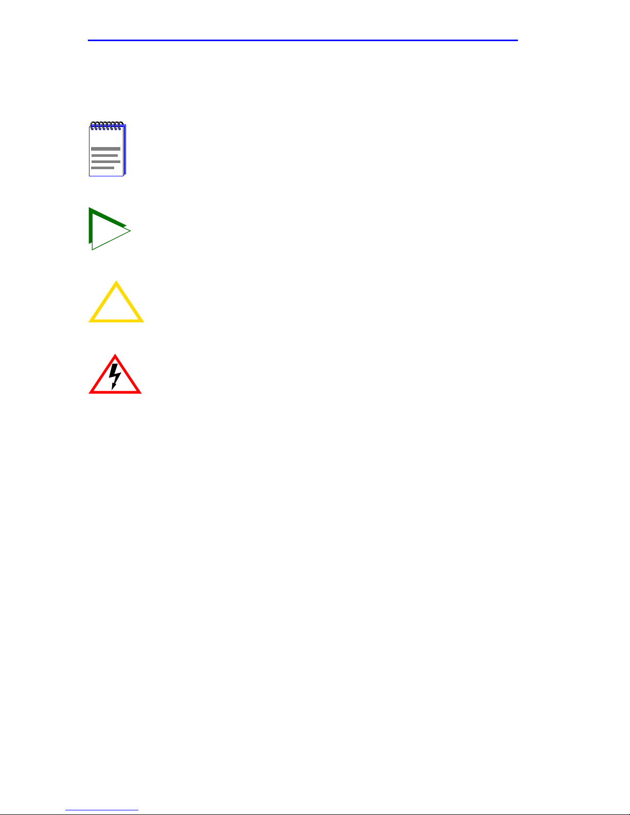
The following conventions may be used in this document:
Note
symbol. Calls the reader’s attention to any item of
NOTE
TIP
information that may be of special importance.
Tip
symbol. Conveys helpful hints concerning procedures or
actions.
!
CAUTION
Caution
damage to the equipment.
Electrical Hazard Warning
that could result in personal injury or death due to an electrical
hazard.
symbol. Contains information essential to avoid
symbol. Warns against an action
xvi SWPIM-SY Installation Guide
Page 19

Introduction
GETTING HELP
For additional support related to this device or document, contact
Cabletron Systems using one of the following methods:
World Wide Web http://www .cabletron.com/
Phone (603) 332-9400
Internet mail [email protected]
FTP ftp://ftp.cabletron.com/
Login
Password
To send comments or suggestions concerning this document, contact the
Cabletron Systems Technical Writing Department via the following
email address:
Make sure to include the document Part Number in the email message.
anonymous
your email address
Before calling Cabletron Systems, have the following information
ready:
•
Your Cabletron Systems service contract number
•
A description of the failure
•
A description of any action(s) already taken to resolve the problem
(e.g., changing mode switches, rebooting the unit, etc.)
•
The serial and revision numbers of all involved Cabletron Systems
products in the network
•
A description of your network environment (layout, cable type, etc.)
•
Network load and frame size at the time of trouble (if known)
•
The device history (i.e., have you returned the device before, is this a
recurring problem, etc.)
•
Any previous Return Material Authorization (RMA) numbers
SWPIM-SY Installation Guide xvii
Page 20

Introduction
xviii SWPIM-SY Installation Guide
Page 21

CHAPTER 1
INSTALLATION
Only qualified personnel should install the SWPIM-SY.
This chapter covers the following items:
•
Unpacking the SWPIM-SY (Section 1.1)
•
Installing the SWPIM-SY into the host platform (Section 1.2)
•
A description of the LANVIEW LED indications (Section 1.3)
•
Connecting the SWPIM-SY to the network (Section 1.4)
•
What to do once the SWPIM-SY is installed (Section 1.5)
1.1 UNPACKING THE SWPIM-SY
Use static electricity precautions when handling the SWPIM-SY.
1. Open the packing box and remove the SWPIM-SY.
2. Attach the antistatic strap (refer to the instructions in the antistatic
wrist strap package) before removing the SWPIM-SY from the
antistatic packaging.
Failure to observe static safety precautions could cause
!
CAUTION
3. Verify that the SWPIM-SY is undamaged. Refer to Getting Help if
there is any damage to the device. Do not attempt to install the
SWPIM-SY if it is damaged.
damage to the SWPIM-SY. Follow static safety handling rules
and wear the antistatic wrist strap shipped with the SWPIM-SY.
Do not cut the non-conductive bag to remove the device.
Damage could result from sharp objects contacting the device
or components.
SWPIM-SY Installation Guide 1-1
Page 22

Chapter 1: Installation
1.2 INSTALLING THE SWPIM-SY
The SWPIM-SY can be installed in any available open slot in the host
platform. To install the SWPIM-SY, proceed as follows:
1. You do not need to power down the host platform to install the
SWPIM-SY. The SWPIM-SY can be installed into the host platform
with the power on or off.
2. Remove the blank panel covering the slot in the host platform in which
the SWPIM-SY will be installed, by prying it off the faceplate.
3. Ensure that the antistatic wrist strap is attached and employed as
recommended.
Observe all precautions to prevent damage from Electrostatic
!
CAUTION
Discharge (ESD).
4. Remove the SWPIM-SY from the plastic bag. (Save the bag in the
event the device must be removed from the host platform).
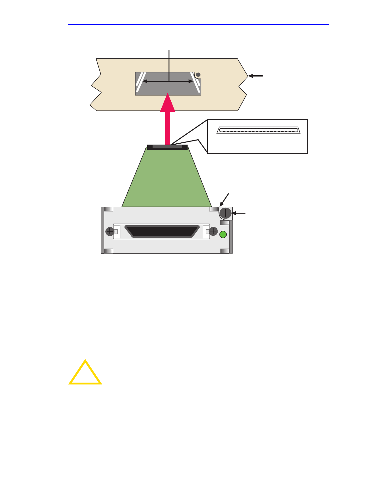
5. Hold the SWPIM-SY with the faceplate facing away (right side up)
from the host platform. The 40-pin connector should be facing towards
the empty slot, with the wide part of the connector oriented down. See
Figure 1-1.
6. Locate the rail guides inside the slot in which the SWPIM-SY will be
installed. See Figure 1-1.
7. Install the SWPIM-SY in the host platform by aligning the
SWPIM-SY with the rail guides in the host platform and sliding it in.
Take care that the SWPIM-SY slides in straight and properly engages
the backplane host connector. Do not force the device.
1-2 SWPIM-SY Installation Guide
Page 23
Rail Guides
Installing the SWPIM-SY
Host Platform
20
View of Host Connector End of
SWPIM-SY
SWPIM-SY
Network Connector End
2140
1
Thumbscrew
SWPIM-SY
LNK
3001
Figure 1-1 Installing the SWPIM-SY into the Host Platform
8. Fasten the SWPIM-SY with the thumbscrew.
9. Replace power to the host platform, if necessary. Check to see that the
host platform LED indicators go to their normal configuration. If they
do not, remove the SWPIM-SY from the host platform and contact
Cabletron Systems.
Do not connect any WAN cables until the SWPIM-SY has been
!
CAUTION
configured in software. The phone company can shut down a
line that has an unconfigured connection on it.
10. The SWPIM-SY must be configured before the WAN connection is
made. Once the SWPIM-SY has been configured, the host platform
must undergo a soft or hard restart in order for the SWPIM-SY to be
recognized and for traffic to pass. Refer to the appropriate software
manual to configure the SWPIM-SY.
SWPIM-SY Installation Guide 1-3
Page 24
Chapter 1: Installation
1.3 LANVIEW LED INDICATIONS
Refer to Table 1-1 for the link LED indications for the SWPIM-SY. The
link LED is multicolored and will display different colors and on/of f rates
to indicate different situations.
Table 1-1 Link LED
Color Indication
Off Disabled or not configured
Red No Link
Amber Transmit or Receive Traffic
Blinking Amber Loopback Test Mode
Green Port is Active
Blinking Green Port is in test mode
1.4 CONNECTING TO THE NETWORK
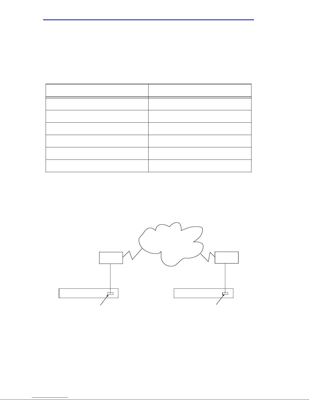
Figure 1-2 depicts a common configuration for the SWPIM-SY. It is
shown only as an example of a setup used for the SWPIM-SY.
WAN
CSU/DSU
SSR-600
CSU/DSU
Site 1
SSR-600
SWPIM-SY SWPIM-SY
Site 2
Figure 1-2 Common Configuration for the SWPIM-SY
1-4 SWPIM-SY Installation Guide
Page 25
Completing the Installation
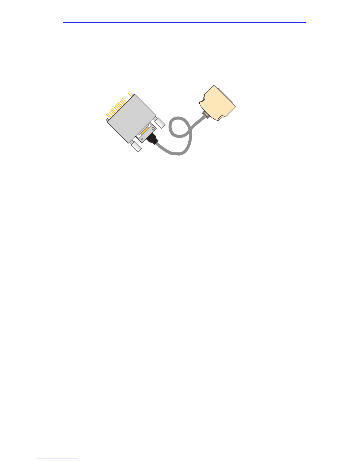
Figure 1-3 shows the V.35 cable typically used for connecting the
SWPIM-SY to the network. One end has thumbscrews to attach, and the
other uses a push-release mechanism whereby the connector is removed
by squeezing the release buttons.
Cabletron Part Number 9380413
Figure 1-3 V.35 Cable
1.5 COMPLETING THE INSTALLATION
After installing the SWPIM-SY, the SWPIM-SY will need to be
configured for the network. Refer to the host platform documentation in
order to set up and manage the SWPIM-SY using the software.
SWPIM-SY Installation Guide 1-5
Page 26

Chapter 1: Installation
1-6 SWPIM-SY Installation Guide
Page 27

APPENDIX A
SPECIFICATIONS
This section describes the environmental specifications, and safety and
approval requirements for the SWPIM-SY. Cabletron Systems reserves
the right to change these specifications at any time without notice.
A.1 PHYSICAL PROPERTIES
Dimensions: 1.98 H x 5.40 W x 19.35 D (cm)
0.78 H x 2.125 W x 7.62 D (in)
Weight (Unit): .068 kg (0.15 lb)
Nominal current draw on +5V
supply from host platform: 350 mA
MTBF (Predicted):
65,681,445 hours
A.2 NETWORK INTERFACE
The SWPIM-SY uses a 36-pin AMP female connector for the network
port that supports the electrical signal interfaces in T able A-1. T able A-1
also shows the minimum and maximum speeds of the
Synchronous/Asynchronous module:
Table A-1 Interface Performance
Interface Minimum Speed Maximum Speed
EIA- 232-D 1.2 Kbps 256 Kbps
EIA- 449 1.2 Kbps 8 Mbps
V.35 1.2 Kbps 8 Mbps
X.21 1.2 Kbps 8 Mbps
EIA-530 1.2 Kbps 8 Mbps
EIA-530A 1.2 Kbps 8 Mbps
SWPIM-SY Installation Guide A-1
Page 28

Appendix A: Specifications
The network interface pin assignments for the network connector are
listed in T able A-2. “Dir. To” indicates the direction of the signal.
Table A-2 Network Interface Connector Pin Assignment
Signal Dir . T o Pin Signal Dir. T o Pin
GND - 1 CID0 - 19
CID1_ - 2 CID2_ - 20
DCEDTE_ - 3 GND - 21
DSR_A DTE 4 DSR_B DTE 22
TXD_A DCE 5 TXD_B DCE 23
DCD_A DTE 6 DCD_B DTE 24
GND - 7 GND - 25
RTS_A DCE 8 RTS_B DCE 26
CTS_A DTE 9 CTS_B DTE 27
RXD_A DTE 10 RXD_B DTE 28
RI DTE 11 TM DTE 29
NC - 12 CID3_ - 30
RXC_A DTE 13 RXC_B DTE 31
DTR_A DCE 14 DTR_B DCE 32
SCTE_A DCE 15 SCTE_B DCE 33
GND - 16 GND - 34
TXC_A DTE 17 TXC_B DTE 35
LL DCE 18 RL DCE 36
SHIELD - M1 SHIELD - M2
Note:
CIDn = Cable Identity (n)
LL = Local Loopback
DCEDTE = DCE (High) or DTE (Low)
RL = Remote Loopback
TM = Test Mode
A-2 SWPIM-SY Installation Guide
Page 29

Environmental Requirements
A.3 ENVIRONMENTAL REQUIREMENTS
Operating Temperature: +5° to +40°C (41° to 104°F)
Non-operating Temperature: -30° to +90°C (-22° to 194°F)
Operating Humidity: 5% to 90% (Non-condensing)
A.4 REGULATORY COMPLIANCE
Safety
UL 1950 (without D3 deviations), CSA C22.2
No. 950, and EN 60950
EMI
FCC Part 15 Class A, EN 55022 Class A and
VCCI Class I
Electromagnetic
Compatibility (EMC)
EN 50082-1 including: IEC 801-2 (ESD), IEC
801-3 (Radiated Susceptibility), and IEC
801-4 (EFT/B)
NEBS TR-NWT-000063: Network Equipment
Building System (NEBS) Generic Equipment
Requirements
GR-1089-CORE: EMC and Electrical Safety
Generic Criteria for Network
Telecommunications Equipment
Telecom CTR-2 Compliant, listed under
TUV-Rheinland
SWPIM-SY Installation Guide A-3
Page 30

Appendix A: Specifications
A-4 SWPIM-SY Installation Guide
Page 31

APPENDIX B
CABLES AND PINOUTS
This appendix provides Cabletron Systems part numbers and connector
pinouts for the following interface cables:
• EIA-449
• CCITT V.35
• EIA-232
• CCITT X.21
• EIA-530
• EIA-530A
B.1 INTERFACE CABLE PART NUMBERS
Table B-1 lists the DTE interface cable part numbers and table numbers
for the SWPIM-SY. The standard length for all cables is 10 feet.
Table B-1 DTE Interface Cable Types and Cabletron Part Numbers
Interface T ype Maximum
Length (feet)
RS449 500 9380414 Table B-3
CCITT V.35 200 9380413 Table B-4
RS232 50 9380412 Table B-5
CCITT X.21 500 9380410 Table B-6
EIA-530 500 9380411 Table B-7
EIA-530A 500 9380420 Table B-8
Cabletron Part
Number
Table Number
SWPIM-SY Installation Guide B-1
Page 32
Appendix B: Cables and Pinouts
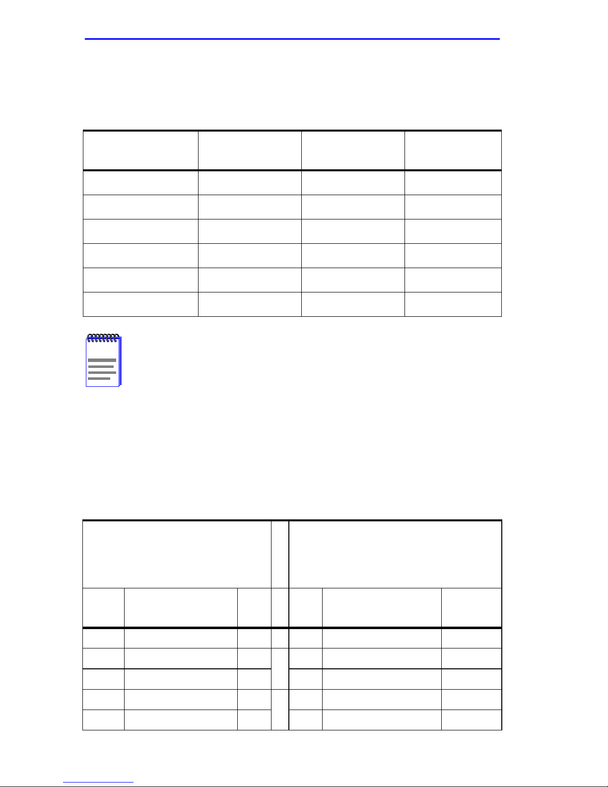
Table B-2 lists the DCE interface cable part numbers and table numbers
for the SWPIM-SY. The standard length for all cables is 10 feet.
Table B-2 DCE Interface Cable Types and Cabletron Part Numbers
Interface T ype Maxim um
Length (feet)
Cabletron Part
Number
Table Number
RS449 500 9380419 Table B-9
CCITT V.35 200 9380418 Table B-10
RS232 50 9380415 Table B-11
CCITT X.21 500 9380417 Table B-12
EIA-530 500 9380416 Table B-13
EIA-530A 500 9380421 Table B-14
For all the f ollowing tab les , “Dir To” indicates the direction of the
NOTE
signal.
Notes at the bottom of all the tables in this Appendix are
supplied as reference information for cable construction. They
can be ignored if the cable has been supplied by the vendor.
B.2 RS449 / DTE CABLE
Cable Part Number: 9380414
Table B-3 RS449 / DTE Cable
Connector # 1
(36 Pin Male Conn. w/Back Shell)
RS449 / DTE
Dir
To
DTE DSR-A DCE Ready 4
DTE DSR-B DCE Ready 22 29 DSR-B DCE Mode DM
DCE TXD-A Transmit Data 5
DCE TXD-B Tr ansmit Data 23 22 TXD-B T r ansmit Data SD
Signal Name Pin
#
Signal Common 25 20 Signal common RC
Connector # 2
P
(DB 37 Pin Male Conn. w/Back Shell)
A
I
RS449 / DCE
R
Pin #Signal Name Mne-
11 DSR-A DCE Mode DM
A
4 TXD-A Transmit Data SD
B
monic
B-2 SWPIM-SY Installation Guide
Page 33

RS449 / DTE Cable
Table B-3 RS449 / DTE Cable (Continued)
Connector # 1
(36 Pin Male Conn. w/Back Shell)
RS449 / DTE
Dir
To
DTE DCD-A Receiver Ready 6
DTE DCD-B Receiver Ready 24 31 DCD-B Receiver Ready RR
DCE RTS-A Req. to Send 8
DCE RTS-B Req. to Send 26 25 RTS-B Req. to Send RS
DTE CTS-A Clear to Send 9
DTE CTS-B Clear to Send 27 27 CTS-B Clear to Send CS
DTE RXD-A Receive Data 10
DTE RXD-B Receive Data 28 24 RXD-B Receive Data RD
DTE RI Ring Indicator 11 15 RI Incoming Call IC
Signal Name Pin
#
Connector # 2
P
(DB 37 Pin Male Conn. w/Back Shell)
A
I
RS449 / DCE
R
Pin #Signal Name Mne-
monic
13 DCD-A Receiver Ready RR
C
7 RTS-A Req. to Send RS
D
9 CTS-A Clear to Send CS
E
6 RXD-A Receive Data RD
F
DTE RXC-A Receive Timing 13
DTE RXC-B Receive Timing 31 26 RXC-B Receive Timing RT
DCE DTR-A Terminal Ready 14
DCE DTR-B Terminal Ready 32 30 DTR-B Terminal Ready TR
DCE SCTE-A Tr ansmit Timing 15
DCE SCTE-B Tr ansmit Timing 33 35 SCTE-B T erminal Timing TT
DTE TXC-A Transmit Timing 17
DTE TXC-B Transmit Timing 35 23 TXC-B Send Timing ST
DCE LL Local Loopback 18 10 LL Local Loopback LL
DTE TM Test Mode 29 18 TM Test Mode TM
DCE RL Remote Loopback 36 14 RL Remote Loopback RL
DTE DCEDTE_ *3/7
DTE CID1 Cable ID *2/21
Signal Common 16
8 RXC-A Receive Timing RT
G
12 DTR-A T erminal Ready TR
H
17 SCTE-A T erminal Timing TT
I
5 TXC-A Send Timing ST
J
19 37Signal Ground / Signal
common
SG / SC
Shield DRAIN 1
Note: * For DTE attach DCEDTE_ pin #3 to pin #7
* For Cable ID attach CID1 pin #2 to pin #21
SWPIM-SY Installation Guide B-3
Page 34

Appendix B: Cables and Pinouts
B.3 CCITT V.35 / DTE CABLE
Cable Part Number: 9380413
Table B-4 CCITT V.35 /DTE Cable
Connector # 1
(36 Pin Male Conn. w/Back
Shell)
CCITT V.35 / DTE
Connector # 2
P
(M Series 34 Pin Male Conn.
A
w/Back Shell)
I
R
CCITT V.35 / DCE
DirTo Signal Name Pin # Pin # Signal Name Mne-
monic
DCE TXD-A Transmit Data 5
DCE TXD-B Transmit Data 23 S TXD-B Transmit Data 103
DTE RXD-A Receive Data 10
DTE RXD-B Receive Data 28 T RXD-B Receive Data 104
DTE CTS Clear to Send 9 D CTS Clear to Send 106
DCE RTS Req. to Send 8 C RTS Req. to Send 105
DTE DCD Carrier Detect 6 F DCD Carrier Detect
DTE TXC-A T ransmit Timing 17
DTE TXC-B T ransmit Timing 35 AA TXC-B Transmit Timing 114
P TXD-A Transmit Data 103
A
R RXD-A Receive Data 104
B
Y TXC-A Transmit Timing 114
C
DTE RXC-A Receive Timing 13
DTE RXC-B Receive Timing 31 X RXC-B Receive Timing 115
DCE SCTE-A Transmit Timing 15
DCE SCTE-B Transmit Timing 33 W SCTE-B T ransmit Timing 113
DTE RI Ring Indicator 11 J RI Ring Indicator 125
DCE RL Remote Loopback 36 N RL Remote Loopback 140
DCE LL Local Loopback 18 L LL Local Loopback 141
DTE TM Test Mode 29 NN TM Test Mode 142
DTE DSR DCE Set Ready 4 E DSR Data Set Ready 107
DCE DTR DTE Term Ready 14 H DTR Data Term Ready 108
V RXC-A Receive Timing 115
D
U SCTE-A Transmit Timing 113
E
B-4 SWPIM-SY Installation Guide
Page 35
CCITT V.35 / DTE Cable
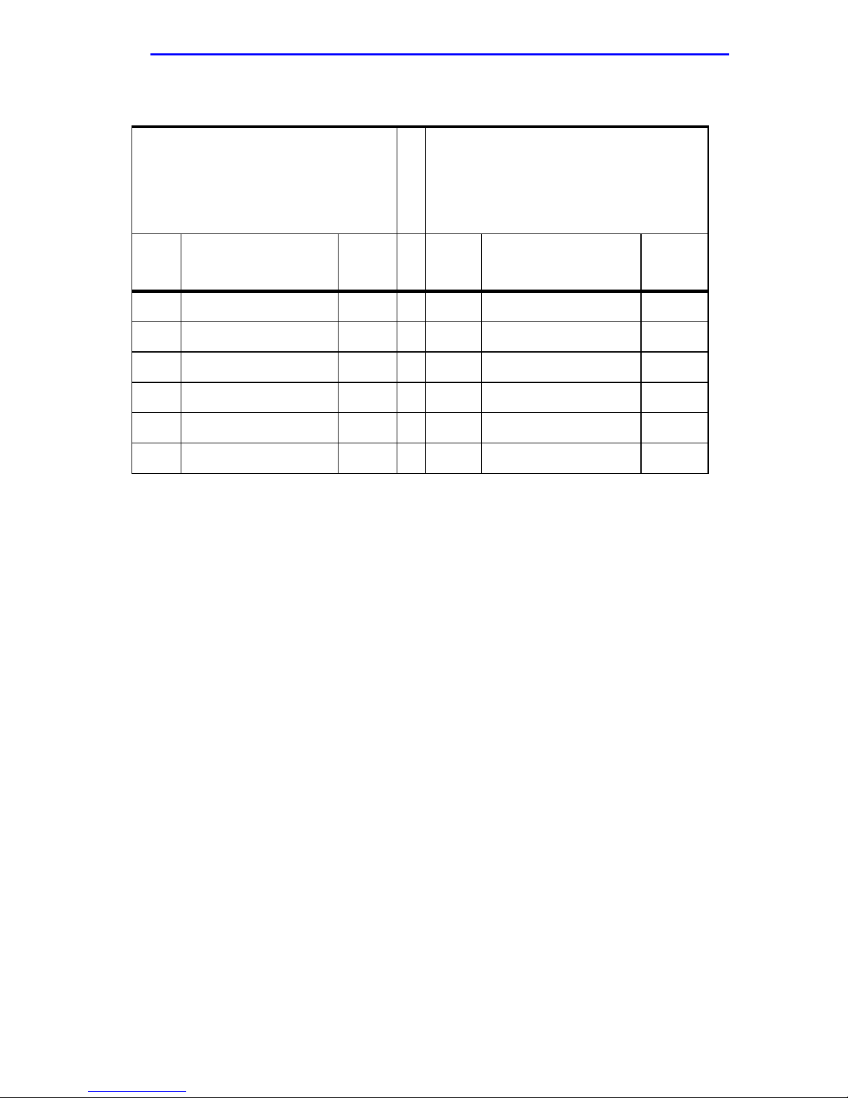
Table B-4 CCITT V.35 /DTE Cable (Continued)
Connector # 1
(36 Pin Male Conn. w/Back
Shell)
CCITT V.35 / DTE
Connector # 2
P
(M Series 34 Pin Male Conn.
A
w/Back Shell)
I
R
CCITT V.35 / DCE
DirTo Signal Name Pin # Pin # Signal Name Mne-
monic
DTE CID0 Cable ID *19/21
DTE CID1 Cable ID * 2/21
DTE DCEDTE_ * 3/7
Signal Ground 25 A Signal Ground
Signal common 16 B Signal Common 102
Shield DRAIN 1
Note: * For DTE attach DCEDTE_ pin #3 to pin #7
* For Cable ID attach CID0 pin #19 to pin #21
* For Cable ID attach CID1 pin #2 to pin #21
SWPIM-SY Installation Guide B-5
Page 36

Appendix B: Cables and Pinouts
B.4 RS232 / DTE CABLE
Cable Part Number: 9380412
Table B-5 RS232 / DTE Cable
Connector # 1
(36 Pin Male Conn. w/Back Shell)
RS232 / DTE
Connector # 2
P
(DB 25 Pin Male Conn. w/Back
A
Shell)
I
R
RS232 / DCE
DirTo Signal Name Pin # Pin #Signal Name Mne-
monic
DCE TXD Transmit Data 5 2 TXD Transmit Data BA
DTE RXD Receive Data 10 3 RXD Receive Data BB
DTE CTS Clear to Send 9 5 CTS Clear to Send CB
DCE RTS Req. to Send 8 4 RTS Req. to Send CA
DTE DCD Carrier Detect 6 8 DCD Carrier Detect
DTE TXC Tr ansmit Timing 17 15 TXC Transmit Timing DB
DTE RXC Receive Timing 13 17 RXC Receive Timing DD
DCE SCTE Transmit Timing 15 24 SCTE Transmit Timing DA
DTE RI Ring Indicator 11 22 RI Ring Indicator CE
DCE RL Remote Loopback 36 21 RL Remote Loopback RL
DCE LL Local Loopback 18 18 LL Local Loopback LL
DTE TM Test Mode 29 25 TM Test Mode TM
DTE DSR DCE Ready 4 6 DSR DCE Ready CC
DCE DTR DTE Ready 14 20 DTR DTE Ready CD
DTE CID0 Cable ID *19/21
DTE DCEDTE_ * 3/7
Signal Common 16 7 Signal Common AB
Shield DRAIN 1
Note: * For DTE attach DCEDTE_ pin #3 to pin #7
* For Cable ID attach CID0 pin #19 to pin #21
B-6 SWPIM-SY Installation Guide
Page 37
B.5 CCITT X.21 / DTE CABLE
Cable Part Number: 9380410
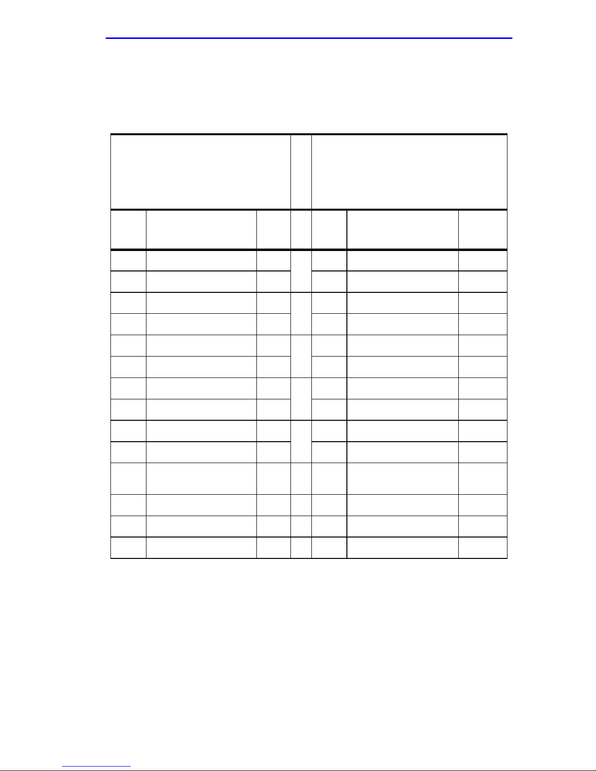
Table B-6 CCITT X.21 / DTE Cable
CCITT X.21 / DTE Cable
Connector # 1
(36 Pin Male Conn. w/Back
Shell)
CCITT X.21 / DTE
Dir
To
DCE TXD-A Transmit Data 5
DCE TXD-B Transmit Data 23 9 TXD-B Transmit Data T
DTE RXD-A Receive Data 10
DTE RXD-B Receive Data 28 11 RXD-B Receive Data R
DTE CTS-A Clear to Send 9
DTE CTS-B Clear to Send 27 12 CTS-B Clear to Send I
DCE RTS-A Req. to Send 8
DCE RTS-B Req. to Send 26 10 RTS-B Req. to Send C
Signal Name
Pin
#
Connector # 2
P
(DB 15 Pin Male Conn. w/Back
A
Shell)
I
R
CCITT X.21 / DCE
Pin
#
2 TXD-A Transmit Data T
A
4 RXD-A Receive Data R
B
5 CTS-A Clear to Send I
C
3 RTS-A Req. to Send C
D
Signal Name
Mnemonic
DTE RXC-A Receive Timing 13
DTE RXC-B receive Timing 31 13 RXC-B receive Timing S
DTE CID2 Cable ID
DTE DCEDTE_ *3/7
Signal Common 16 8 Signal Common G
Shield DRAIN 1
Note: * For DTE attach DCEDTE_ pin #3 to pin #7
* For Cable ID attach CID2 pin #20 to pin #21
*20/2
1
6 RXC-A Receive Timing S
E
SWPIM-SY Installation Guide B-7
Page 38
Appendix B: Cables and Pinouts
B.6 EIA-530 / DTE CABLE
Cable Part Number: 9380411
Table B-7 EIA-530 / DTE Cable
Connector # 1
(36 Pin Male Conn. w/Bac k Shell)
EIA-530 / DTE
Connector # 2
P
(DB 25 Pin Male Conn. w/Back
A
Shell)
I
R
EIA-530 / DCE
DirTo Signal Name Pin # Pin # Signal Name Mne-
monic
DCE TXD-A Trans. Data 5 A 2 TXD-A Trans. Data BA
DCE TXD-B Trans. Data 23 14 TXD-B Trans. Data BA
DTE RXD-A Rec. Data 10 B 3 RXD-A Rec. Data BB
DTE RXD-B Rec. Data 28 16 RXD-B Rec. Data BB
DTE CTS-A Clear to send 9 C 5 CTS-A Clear to send CB
DTE CTS-B Clear to send 27 13 CTS-B Clear to send CB
DCE RTS-A Req. to Send 8 D 4 RTS-A Req. to Send CA
DCE RTS-B Req. to Send 26 D 19 RTS-B Req. to Send CA
DTE DCD-A Carrier Detect 6 E 8 DCD-A Carrier Detect CF
DTE DCD-B Carrier Detect 24 10 DCD-B Carrier Detect CF
DTE TXC-A T rans. Timing 17 F 15 TXC-A Trans . Timing DB
DTE TXC-B T rans. Timing 35 12 TXC-B Trans. Timing DB
DTE RXC-A Rec. Timing 13 G 17 RXC-A Rec. Timing DD
DTE RXC-B Rec. Timing 31 9 RXC-B Rec. Timing DD
DCE SCTE-A Trans.Timing 15 H 24 SCTE-A Trans.Timing DA
DCE SCTE-B Trans.Timing 33 11 SCTE-B Trans.Timing DA
DCE RL Remote loopback 36 21 RL Remote loopback RL
DCE LL Local Loopback 18 18 LL Local Loopback LL
DTE TM Test Mode 29 25 TM Test Mode TM
B-8 SWPIM-SY Installation Guide
Page 39

EIA-530 / DTE Cable
Table B-7 EIA-530 / DTE Cable (Continued)
Connector # 1
(36 Pin Male Conn. w/Bac k Shell)
EIA-530 / DTE
Connector # 2
P
(DB 25 Pin Male Conn. w/Back
A
Shell)
I
R
EIA-530 / DCE
DirTo Signal Name Pin # Pin # Signal Name Mne-
monic
DTE DSR-A DCE Set Ready 4 I 6 DSR-A DCE Set Ready CC
DTE DSR-B DCE Set Ready 22 22 DSR-B DCE Set Ready CC
DCE DTR-A DTE Term Ready 14 J 20 DTR-A DTE Term Ready CD
DCE DTR-B DTE Term Ready 32 23 DTR-B DTE Term Ready CD
DTE CID1 Cable ID *2/21
DTE CID3 Cable ID *30/21
DTE DCEDTE_ *3/7
Signal Ground 25 1 Signal Ground
Signal Common 16 7 Signal Common AB
Signal DRAIN 1 7
Note: * For DTE attach DCEDTE_ pin #3 to pin #7
* For Cable ID attach CID1 pin #2 to pin #21
* For Cable ID attach CID3 pin #30 to pin #21
SWPIM-SY Installation Guide B-9
Page 40
Appendix B: Cables and Pinouts
B.7 EIA-530A / DTE CABLE
Cable Part Number: 9380420
Table B-8 EIA-530A / DTE
Connector # 1
(36 Pin Male Conn. w/Back Shell)
EIA-530A / DTE
Dir
Signal Name Pin # Pin # Signal Name Mne-
To
DCE TXD-A Trans. Data 5
DCE TXD-B Trans. Data 23 14 TXD-B Trans. Data BA
DTE RXD-A Rec. Data 10
DTE RXD-B Rec. Data 28 16 RXD-B Rec. Data BB
DTE CTS-A Clear to send 9
DTE CTS-B Clear to send 27 13 CTS-B Clear to send CB
DCE RTS-A Req. to Send 8 D 4 RTS-A Req. to Send CA
DCE RTS-B Req. to Send 26 D 19 RTS-B Req. to Send CA
Connector # 2
P
(DB 25 Pin Male Conn. w/Back
A
Shell)
I
R
EIA-530A / DCE
2 TXD-A Trans. Data BA
A
3 RXD-A Rec. Data BB
B
5 CTS-A Clear to send CB
C
monic
DTE DCD-A Carrier Detect 6
DTE DCD-B Carrier Detect 24 10 DCD-B Carrier Detect CF
DTE TXC-A T rans. Timing 17
DTE TXC-B T rans. Timing 35 12 TXC-B T rans. Timing DB
DTE RXC-A Rec. Timing 13
DTE RXC-B Rec. Timing 31 9 RXC-B Rec. Timing DD
DCE SCTE-A Trans .Timing 15
DCE SCTE-B Trans.Timing 33 11 SCTE-B Trans.Timing DA
DTE RI Ring Indicator 11 22 RI Ring Indicator RI
DCE RL Remote loopback 36 21 RL Remote loopback RL
DCE LL Local Loopback 18 18 LL Local Loopback LL
DTE TM Test Mode 29 25 TM Test Mode TM
8 DCD-A Carrier Detect CF
E
15 TXC-A Trans. Timing DB
F
17 RXC-A Rec. Timing DD
G
24 SCTE-A Trans.Timing DA
H
B-10 SWPIM-SY Installation Guide
Page 41

EIA-530A / DTE Cable
Table B-8 EIA-530A / DTE (Continued)
Connector # 1
(36 Pin Male Conn. w/Back Shell)
EIA-530A / DTE
Dir
Signal Name Pin # Pin # Signal Name Mne-
To
DTE DSR DCE Set Ready 4 I 6 DSR DCE Set Ready CC
DCE DTR DTE Term Ready 14 J 20 DTR DTE Term Ready CD
DTE CID2 Cable ID *20/21
DTE CID1 Cable ID *2/21
DTE DCEDTE_ *3/7
Signal Ground 25 1 Signal Ground
Signal Common 16 7 Signal Common AB
Signal Common 34 23 Signal Common AC
Connector # 2
P
(DB 25 Pin Male Conn. w/Back
A
Shell)
I
R
EIA-530A / DCE
monic
Signal DRAIN 1 7
Note: * For DTE attach DCEDTE_ pin #3 to pin #7
* For Cable ID attach CID2 pin #20 to pin #21
* For Cable ID attach CID1 pin #2 to pin #21
SWPIM-SY Installation Guide B-11
Page 42
Appendix B: Cables and Pinouts
B.8 RS449/DCE CABLE
Cable Part Number: 9380419
Table B-9 RS449 / DCE Cable
Connector # 1
(36 Pin Male Conn. w/Bac k Shell)
RS449 / DCE
Dir
To
DTE DSR-A DCE Ready 14
DTE DSR-B DCE Ready 32 29 DSR-B DCE Mode DM
DCE TXD-A Transmit Data 10
DCE TXD-B Transmit Data 28 22 TXD-B Transmit Data SD
DTE DCD-A Receiver Ready 6
DTE DCD-B Receiver Ready 24 31 DCD-B Receiver Ready RR
DCE RTS-A Req. to Send 9
DCE RTS-B Req. to Send 27 25 RTS-B Req. to Send RS
Signal Name Pin
#
Signal Common 25 20 Signal common RC
Connector # 2
P
(DB 37 Pin Female Conn. w/Bac k
A
Shell)
I
R
RS449 / DTE
Pin #Signal Name Mne-
11 DSR-A DCE Mode DM
A
4 TXD-A Transmit Data SD
B
13 DCD-A Receiver Ready RR
C
7 RTS-A Req. to Send RS
D
monic
DTE CTS-A Clear to Send 8
DTE CTS-B Clear to Send 26 27 CTS-B Clear to Send CS
DTE RXD-A Receive Data 5
DTE RXD-B Receive Data 23 24 RXD-B Receive Data RD
DTE RI Ring Indicator 18 15 RI Incoming Call IC
DTE RXC-A Receive Timing 15
DTE RXC-B Receive Timing 33 26 RXC-B Receive Timing RT
DCE DTR-A Terminal Ready 4
DCE DTR-B Terminal Ready 22 30 DTR-B Terminal Ready TR
DCE SCTE-A Transmit Timing 13
DCE SCTE-B Transmit Timing 31 35 SCTE-B Terminal Timing TT
9 CTS-A Clear to Send CS
E
6 RXD-A Receive Data RD
F
8 RXC-A Receive Timing RT
G
12 DTR-A Terminal Ready TR
H
17 SCTE-A Terminal Timing TT
I
B-12 SWPIM-SY Installation Guide
Page 43

RS449/DCE Cable
Table B-9 RS449 / DCE Cable (Continued)
Connector # 1
(36 Pin Male Conn. w/Bac k Shell)
RS449 / DCE
Dir
To
DTE TXC-A T ransmit Timing 17
DTE TXC-B T ransmit Timing 35 23 TXC-B Send Timing ST
DCE LL Local Loopback 11 10 LL Local Loopback LL
DTE TM Test Mode 36 18 TM Test Mode TM
DCE RL Remote Loopback 29 14 RL Remote Loopback RL
DTE CID1 Cable ID *2/21
Signal Name Pin
#
Signal Common 16
Shield DRAIN 1
Connector # 2
P
(DB 37 Pin Female Conn. w/Bac k
A
Shell)
I
R
RS449 / DTE
Pin #Signal Name Mne-
5 TXC-A Send Timing ST
J
19 37Signal Ground Signal
common
monic
SG
SC
Note: * For Cable ID attach CID1 pin #2 to pin #21
SWPIM-SY Installation Guide B-13
Page 44
Appendix B: Cables and Pinouts
B.9 CCITT V.35 / DCE CABLE
Cable Part Number: 9380418
Table B-10 CCITT V.35 / DCE Cable
Connector # 1
(36 Pin Male Conn. w/Bac k Shell)
CCITT V.35 / DCE
Dir
Signal Name Pin # Pin # Signal Name Mne-
To
DCE TXD-A Transmit Data 10
DCE TXD-B Transmit Data 28 S TXD-B Transmit Data 103
DTE RXD-A Receive Data 5
DTE RXD-B Receive Data 23 T RXD-B Receive Data 104
DTE CTS Clear to Send 8 D CTS Clear to Send 106
DCE RTS Req. to Send 9 C RTS Req. to Send 105
DTE DCD Carrier Detect 6 F DCD Carrier Detect
DTE TXC-A Transmit Timing 17
DTE TXC-B Transmit Timing 35 AA TXC-B Transmit Timing 114
Connector # 2
P
(M Series 34 Pin Female Conn.
A
w/Back Shell)
I
R
CCITT V.35 / DTE
P TXD-A Transmit Data 103
A
R RXD-A Receive Data 104
B
Y TXC-A T ransmit Timing 114
C
monic
DTE RXC-A Receive Timing 15
DTE RXC-B Receive Timing 33 X RXC-B Receive Timing 115
DCE SCTE-A T r ansmit Timing 13
DCE SCTE-B T r ansmit Timing 31 W SCTE-B T ransmit Timing 113
DTE RI Ring Indicator 18 J RI Ring Indicator 125
DCE RL Remote Loopback 29 N RL Remote Loopback 140
DCE LL Local Loopback 11 L LL Local Loopback 141
DTE TM Test Mode 36 NN TM Test Mode 142
DTE DSR DCE Set Ready 14 E DSR Data Set Ready 107
DCE DTR DTE Term Ready 4 H DTR Data Term Ready 108
DTE CID0 Cable ID *19/21
V RXC-A Receive Timing 115
D
U SCTE-A Transmit Timing 113
E
B-14 SWPIM-SY Installation Guide
Page 45

CCITT V.35 / DCE Cable
Table B-10 CCITT V.35 / DCE Cable (Continued)
Connector # 1
(36 Pin Male Conn. w/Bac k Shell)
CCITT V.35 / DCE
Dir
Signal Name Pin # Pin # Signal Name Mne-
Connector # 2
P
(M Series 34 Pin Female Conn.
A
w/Back Shell)
I
R
CCITT V.35 / DTE
To
DTE CID1 Cable ID * 2/21
Signal Ground 25 A Signal Ground
Signal common 16 B Signal Common 102
Shield DRAIN 1
Note: * For Cable ID attach CID0 pin #19 to pin #21
* For Cable ID attach CID1 pin #2 to pin #21
monic
SWPIM-SY Installation Guide B-15
Page 46

Appendix B: Cables and Pinouts
B.10 RS232 / DCE CABLE
Cable Part Number: 9380415
Table B-11 RS232 / DCE Cable
Connector # 1
(36 Pin Male Conn. w/Back
Shell)
RS232 / DCE
Dir
Signal Name Pin # Pin # Signal Name Mne-
To
DCE TXD Transmit Data 10 2 TXD Transmit Data BA
DTE RXD Receive Data 5 3 RXD Receive Data BB
DTE CTS Clear to Send 8 5 CTS Clear to Send CB
DCE RTS Req. to Send 9 4 RTS Req. to Send CA
DTE DCD Carrier Detect 6 8 DCD Carrier Detect
DTE TXC Transmit Timing 17 15 TXC T ransmit Timing DB
DTE RXC Receive Timing 15 17 RXC Receive Timing DD
DCE SCTE Transmit Timing 13 24 SCTE Transmit Timing DA
Connector # 2
P
(DB 25 Pin Female Conn. w/Back
A
Shell)
I
R
RS232 / DTE
monic
DTE RI Ring Indicator 18 22 RI Ring Indicator CE
DCE RL Remote Loopback 29 21 RL Remote Loopback RL
DCE LL Local Loopback 11 18 LL Local Loopback LL
DTE TM Test Mode 36 25 TM Test Mode TM
DTE DSR DCE Ready 14 6 DSR DCE Ready CC
DCE DTR DTE Ready 4 20 DTR DTE Ready CD
DTE CID0 Cable ID *19/21
Signal Common 16 7 Signal Common AB
Shield DRAIN 1
Note: * For Cable ID attach CID0 pin #19 to pin #2
B-16 SWPIM-SY Installation Guide
Page 47

B.11 CCITT X.21 / DCE CABLE
Cable Part Number: 9380417
Table B-12 CCITT X.21 / DCE Cable
CCITT X.21 / DCE Cable
Connector # 1
(36 Pin Male Conn. w/Back Shell)
CCITT X.21 / DCE
Dir
Signal Name Pin # Pin # Signal Name Mne-
Connector # 2
P
(DB 15 Pin Female Conn. w/Back
A
Shell)
I
R
CCITT X.21 / DTE
To
DCE TXD-A Transmit Data 10
DCE TXD-B Transmit Data 28 9 TXD-B Transmit Data T
DTE RXD-A Receive Data 5
DTE RXD-B Receive Data 23 11 RXD-B Receive Data R
DTE CTS-A Clear to Send 8
DTE CTS-B Clear to Send 26 12 CTS-B Clear to Send I
DCE RTS-A Req. to Send 9
DCE RTS-B Req. to Send 27 10 RTS-B Req. to Send C
2 TXD-A Transmit Data T
A
4 RXD-A Receive Data R
B
5 CTS-A Clear to Send I
C
3 RTS-A Req. to Send C
D
monic
DTE RXC-A Receive Timing 15
DTE RXC-B receive Timing 33 13 RXC-B receive Timing S
DTE CID2 Cable ID *20/21
Signal Common 16 8 Signal Common G
Shield DRAIN 1
Note: * For Cable ID attach CID2 pin #20 to pin #21
6 RXC-A Receive Timing S
E
SWPIM-SY Installation Guide B-17
Page 48
Appendix B: Cables and Pinouts
B.12 EIA-530 / DCE CABLE
Cable Part Number: 9380416
Table B-13 EIA-530 / DCE Cable
Connector # 1
(36 Pin Male Conn. w/Bac k Shell)
EIA-530 / DCE
Connector # 2
P
(DB 25 Pin Female Conn. w/Back
A
Shell)
I
R
EIA-530 / DTE
DirTo Signal Name Pin # Pin # Signal Name Mne-
monic
DCE TXD-A Trans. Data 10
DCE TXD-B Trans. Data 28 14 TXD-B Trans. Data BA
DTE RXD-A Rec. Data 5
DTE RXD-B Rec. Data 23 16 RXD-B Rec. Data BB
DTE CTS-A Clear to send 8
DTE CTS-B Clear to send 26 13 CTS-B Clear to send CB
DCE RTS-A Req. to Send 9 D 4 RTS-A Req. to Send CA
DCE RTS-B Req. to Send 27 D 19 RTS-B Req. to Send CA
2 TXD-A Trans. Data BA
A
3 RXD-A Rec. Data BB
B
5 CTS-A Clear to send CB
C
DTE DCD-A Carrier Detect 6
DTE DCD-B Carrier Detect 24 10 DCD-B Carrier Detect CF
DTE TXC-A Trans. Timing 17
DTE TXC-B Trans. Timing 35 12 TXC-B T rans . Timing DB
DTE RXC-A Rec. Timing 15
DTE RXC-B Rec. Timing 33 9 RXC-B Rec. Timing DD
DCE SCTE-A T rans.Timing 13
DCE SCTE-B Trans.Timing 31 11 SCTE-B Trans.Timing DA
DCE RL Remote loopback 29 21 RL Remote loopback RL
DCE LL Local Loopback 11 18 LL Local Loopback LL
DTE TM Test Mode 36 25 TM Test Mode TM
DTE DSR-A DCE Set Ready 14
DTE DSR-B DCE Set Ready 32 22 DSR-B DCE Set Ready CC
8 DCD-A Carrier Detect CF
E
15 TXC-A T rans. Timing DB
F
17 RXC-A Rec. Timing DD
G
24 SCTE-A Trans.Timing DA
H
6 DSR-A DCE Set Ready CC
I
B-18 SWPIM-SY Installation Guide
Page 49

EIA-530 / DCE Cable
Table B-13 EIA-530 / DCE Cable (Continued)
Connector # 1
(36 Pin Male Conn. w/Bac k Shell)
EIA-530 / DCE
Connector # 2
P
(DB 25 Pin Female Conn. w/Back
A
Shell)
I
R
EIA-530 / DTE
DirTo Signal Name Pin # Pin # Signal Name Mne-
monic
DCE DTR-A DTE Term Ready 4
DCE DTR-B DTE Term Ready 22 23 DTR-B DTE Term Ready CD
DTE CID1 Cable ID *2/21
DTE CID3 Cable ID *30/21
Signal Ground 25 1 Signal Ground
Signal Common 16 7 Signal Common AB
Signal DRAIN 1 7
Note: * For Cable ID attach CID1 pin #2 to pin #21
* For Cable ID attach CID3 pin #30 to pin #21
20 DTR-A DTE Term Ready CD
J
SWPIM-SY Installation Guide B-19
Page 50

Appendix B: Cables and Pinouts
B.13 EIA-530A / DCE CABLE
Cable Part Number: 9380421
Table B-14 EIA_530A / DCE Cable
Connector # 1
(36 Pin Male Conn. w/Back
Shell)
EIA-530A / DCE
Connector # 2
P
(DB 25 Pin Female Conn. w/Back
A
Shell)
I
R
EIA-530A / DTE
DirTo Signal Name Pin # Pin # Signal Name Mne-
monic
DCE TXD-A Trans. Data 10 A 2 TXD-A Trans. Data BA
DCE TXD-B Trans. Data 28 14 TXD-B Trans. Data BA
DTE RXD-A Rec. Data 5 B 3 RXD-A Rec. Data BB
DTE RXD-B Rec. Data 23 16 RXD-B Rec. Data BB
DTE CTS-A Clear to send 8 C 5 CTS-A Clear to send CB
DTE CTS-B Clear to send 26 13 CTS-B Clear to send CB
DCE RTS-A Req. to Send 9 D 4 RTS-A Req. to Send CA
DCE RTS-B Req. to Send 27 D 19 RTS-B Req. to Send CA
DTE DCD-A Carrier Detect 6 E 8 DCD-A Carrier Detect CF
DTE DCD-B Carrier Detect 24 10 DCD-B Carrier Detect CF
DTE TXC-A T rans . Timing 17 F 15 TXC-A T rans. Timing DB
DTE TXC-B T rans . Timing 35 12 TXC-B Tr ans. Timing DB
DTE RXC-A Rec. Timing 15 G 17 RXC-A Rec. Timing DD
DTE RXC-B Rec. Timing 33 9 RXC-B Rec. Timing DD
DCE SCTE-A Trans.Timing 13 H 24 SCTE-A Trans.Timing DA
DCE SCTE-B Trans.Timing 31 11 SCTE-B Trans.Timing DA
DTE RI Ring Indicator 18 22 RI Ring Indicator RI
DCE RL Remote loopback 29 21 RL Remote loopback RL
B-20 SWPIM-SY Installation Guide
Page 51

EIA-530A / DCE Cable
Table B-14 EIA_530A / DCE Cable (Continued)
Connector # 1
(36 Pin Male Conn. w/Back
Shell)
EIA-530A / DCE
Connector # 2
P
(DB 25 Pin Female Conn. w/Back
A
Shell)
I
R
EIA-530A / DTE
DirTo Signal Name Pin # Pin # Signal Name Mne-
monic
DCE LL Local Loopback 11 18 LL Local Loopback LL
DTE TM Test Mode 36 25 TM Test Mode TM
DTE DSR DCE Set Ready 14 I 6 DSR DCE Set Ready CC
DCE DTR DTE Term Ready 4 J 20 DTR DTE Term Ready CD
DTE CID2 Cable ID *20/21
DTE CID1 Cable ID *2/21
Signal Ground 25 1 Signal Ground
Signal Common 16 7 Signal Common AB
Signal Common 34 23 Signal Common AC
Signal DRAIN 1 7
Note: * For Cable ID attach CID2 pin #20 to pin #21
* For Cable ID attach CID1 pin #2 to pin #21
SWPIM-SY Installation Guide B-21
Page 52

Appendix B: Cables and Pinouts
B-22 SWPIM-SY Installation Guide
 Loading...