

Page 1
1 2 3
STS-5SU Internal Stacker Unit
Introduction
The SmartStack STS-5SU Internal Stacker Unit is a 4-port
interf ace modul e th a t is in stalled in to th e r ear slot of an y
SmartStack Token Ring Switch. When five SmartStack
switches are connected together through the SmartStack STS5SU module, the switches combine to form one logical switch.
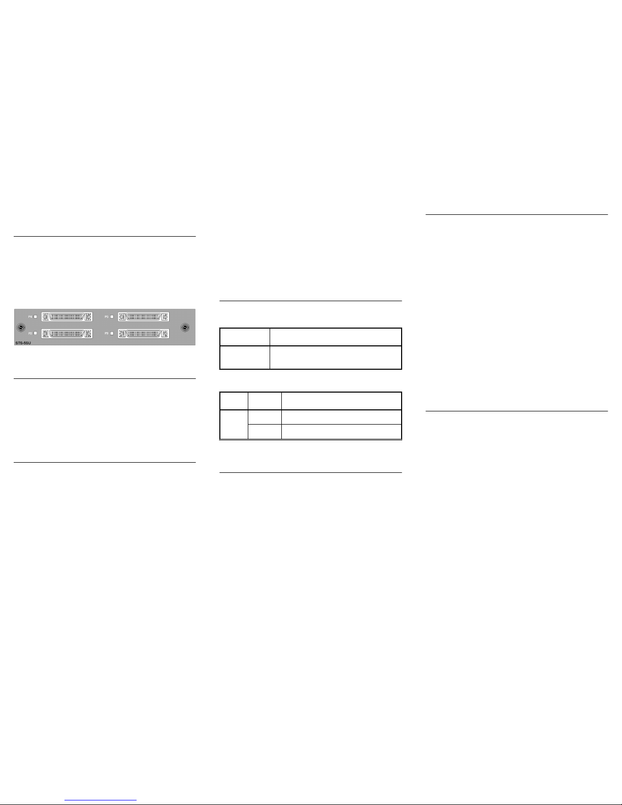
The SmartStack STS-5SU front panel is shown in Figure 1.
Figure 1. SmartStack STS-5SU Front Panel
SmartStack STS-5SU Package Contents
The SmartStack STS-5SU package contain s the following
items:
•
One SmartStack STS-5SU Internal Stacker Unit for the
Cabletron SmartStack Token Ring Switch
•
One SmartStack STS-5SU Ins tallation Guide (thi s
document)
Installation
Use the fo ll owing steps w h en in stalling the Sm ar t S ta ck S TS 5SU module in the SmartStack switch.
Note:
SmartStack STS-5 SU modules are
not
hot-swappable.
Always be sure that the power is off before installing or
removing a module. If the power is on, damage to the
equipment may result. Once the module is installed in the
switch, external cables may be connected or rem oved without
having to remove po wer from the switch.
1. Disconnect power to the switch.
2. If a blank cover is ove r the stacker slot on the back panel,
remove it by unscrewing the two attachm ent screws.
3. To pr e v ent p os sible st atic da mage t o t he module, hol d it by
its edges only. Be careful not to touch the top or bottom.
4. Slide the mod ule int o t he slot e ven ly, ta king ca re to line up
the edges with the guides.
5. Seat the module by pressing the front of the module with
your thumbs.
6. Secure the module to the chass is by tightening the thumb
(panel) screws a t the l eft and righ t e dges of the fr ont panel .
Do not overtighten the screws.
7. Return power to the switch.
SmartStack STS-5SU Connectors and LEDs
The foll owing ta bl es d escr i be th e co nn ec tors an d LEDs on t he
SmartStack STS-5SU front panel.
Connecting the Stacker Link Cable
A proprietary 50-pin cable must be use d to connect ports on
the SmartStack STS - 5SU module with up to four Smar tStack
STS-LM Link Modules in other SmartStack switches. Five
switches can be combined in this way to form a very costeffectiv e stack of switches.
Note:
The SmartStack STS-5SU Internal Stacker Unit must
only be connected to Smart Stack STS-LM Li nk Modules. You
cannot create a stack by connecting SmartStack STS-5SU
modules together.
When inserting the cable connector, keep the c onnector
straight to minimize the ris k of bent or damaged pins.
W orking With a Stack
When the SmartStack switch powers up, it runs through a
series of diagnostics. I mmedi ately after the diagnostics are
complete, the SmartStack switch enters the stack discovery
mode. The discovery mode is used to sense if the unit is cabled
to other units. If the SmartStack switch through a SmartStack
STS-5SU is connected to other units during the discovery
mode, the switches automatically combine to form a stack.
Each unit is assigned a box number. The swit ch with the lowe r
MAC address becomes Box 1, the swi tch with the higher
MAC address becomes Box 2 and so forth. When accessing
switch specific settings from a management consol e, you will
be prompted for a box number.
The switches in the stack combi ne certain configuration
parameters so that th e st ack as a u ni t uses one set of
parameters. These parameters are discussed below in “InterBox Parameters”.
The stack can now be managed as a single enti ty from a
management console or management application.
Inter-Box Parameters
The SmartStac k switches participating in the stack must
combine configuratio n information so that the s tack as a whole
uses common parameters. One of the participating switches
becomes the provider of inter-box parameters.
If the switches have the same configuration information, the
switch that becomes Box 1 becomes the provider. If the
configuration information is different, a split-stack will be
formed and a warning message will be displayed on the
console screen. You will be requested to briefly press the
SysReq button on the switch that is t o be the provider of interbox parameters. When you have sel ec ted the provider, the
other switch will replace its stack related configura tion
parameters with those of the provider.
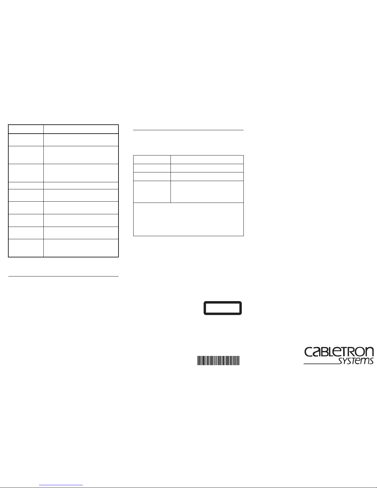
Table 3 lists the inter-b ox parameters.
Connector Description
P2–P5 50-pin SCSI-2 connector for proprietary
Stacker Link cable.
T able 1. SmartStack STS-5SU Network Connector
LED State Description
P2–P5 Off No connection has been esta blished.
On A connection has been established.
T able 2. SmartStack STS-5SU LINK LEDs
Page 2
4
Checking the Installation
The SmartStack Token Ring Switch performs a diagnostic
self-test during the power on cycle. From a management
console, check that the switch lists the SmartStack STS-5SU
port along with the switch ports and that there are no error
messages. The SmartStack STS-5SU port will be listed as port
29.
If, after installation, there is poor system performance or the
SmartStack STS-5SU modul e does not work a t all, r emove the
module and check for any damaged or bent connec tor pins.
You may need a bright light to see inside the stacker slot to
check for bent pins. Also, veri fy that the module is set firmly
in place.
❏
Getting in Touch With Te chnic al Suppor t
For additional su pport related to this device or document,
contact Cabletron Sys tems using one of the following
methods
:
Menu Parameter
IP Configuration IP Address, IP Gateway, IP Subnet, IP
State
Spanning Tree STP Enabling/Dis abling, STP Switch
Priority, STP Maximum Aging, STP
Hello Time, STP Forward Delay
Virtual LAN
Name
Configuration
Changing VLAN names
Password System password
Console
Configuration
Console Time-out
Telnet
Configuration
Number of Allowed Telnet Sessions,
Disallow New Telnet Sessions
TFTP Download TFTP Server Address, Download
Domain, Download Filename
Switch/Sta ck
Information
Stack Timeout, System Name, System
Contact, System Location
SNMP
Configuration
Send Authentication Traps, changing
the Trap table in any wa y, chang i ng th e
Community Name table in any wa y
Ta ble 3. Inter-Box Parameters
World Wide Web http://www.cabletron.com/
Phone (603) 332-9400
Internet mail [email protected]
FTP ftp://ftp.cabletron.com/
Login
anonymous
Password
your email address
To send comments or suggestions concerning this
document, contact the Cabletron Systems Technical
Writing Department via the following email
address: [email protected]
Make sure to include t he document Part Number in the
email message.
STS-5SU Internal Stacker Unit
for
SmartStack Token Ring Switch
Installation Guide
Trademarks
SmartStack is a trademark Cabletron Systems, Inc. All other brands or product names are trademarks or
registered trademarks of their respective holders.
Copyrights
Cabletron reserves the right to modify the information give n in this publication without p rior notice. The
warranty terms and conditions applicable for your purchase of this equipment are given at the time of
purchase. Please consult them for details.
All rights reserved
. No part of this publication may be reproduced, stored in a retrieval system, or
transmitted, in any form or by any means, electronic, mechanical, photocopying, recording or otherwise,
without the prior written permission of the publisher.
Publication: OC-7 058 v. 1.0, 710001 714
Part Number: 9032992
©
February 1 999 by Cabletron Systems, Inc.
FCC Compliance
This equipment has been tested and found to comply with th e limits for a C lass A d igital dev ice, pursuan t
to Part 15 of the FCC Rules. These limits are designed to provide reasonable protection against harmful
interference when the equipment is operated in a commercial environment. This equipment generates,
uses and can radiate radio frequency energy and, if not installed and used in accordance with the
instruction manual, may cause harmful interference to radio communications. Operation of this
equipment in a residential area is likely to cause harmful interference in which case the user will be
required to correct the interference at his own expense.
This device complies with part 15 of the FCC Rules. Operation is subject to the following two
conditions: (1) This device may not cause harmful interference, and (2) this device must accept any
interference received, including interference that may cause undesired operation.
CLASS 1 LASER PRODUCT
*710001714*
 Loading...