

Page 1

ST-500
ETHERNET/IEEE 802.3
TRANSCEIVER WITH LANVIEW
INSTALLATION GUIDE
CABLETRON SYSTEMS, P. O. Box 5005, Rochester, NH 03866-5005
Page 2

NOTICE
Cabletron Systems reserves the right to make changes in specifications
and other information contained in this document without prior notice.
The reader should in all cases consult Cabletron Systems to determine
whether any such changes have been made.
The hardware, firmware, or software described in this manual is subject
to change without notice.
IN NO EVENT SHALL CABLETRON SYSTEMS BE LIABLE FOR ANY
INCIDENTAL, INDIRECT, SPECIAL, OR CONSEQUENTIAL DAMAGES WHATSOEVER (INCLUDING BUT NOT LIMITED TO LOST PROFITS) ARISING OUT OF OR RELATED TO THIS MANUAL OR THE
INFORMATION CONTAINED IN IT, EVEN IF CABLETRON SYSTEMS
HAS BEEN ADVISED OF, KNOWN, OR SHOULD HAVE KNOWN, THE
POSSIBILITY OF SUCH DAMAGES.
© Copyright March 1995 by:
Cabletron Systems, Inc.,
P.O. Box 5005, Rochester, NH 03866-5005
All Rights Reserved
Printed in the United States of America
Part Number: 9030008-02 March 1995
LANVIEW
Ethernet
is a registered trademark of Cabletron Systems, Inc.
is a trademark of Xerox Corp.
ST-500 INSTALLATION GUIDE i
Page 3

FCC NOTICE
This device complies with Part 15 of the FCC rules. Operation is subject
to the following two conditions: (1) this device may not cause harmful interference, and (2) this device must accept any interference received, including interference that may cause undesired operation.
NOTE:
limits for a Class A digital device, pursuant to Part 15 of the FCC rules.
These limits are designed to provide reasonable protection against
harmful interference when the equipment is operated in a commercial
environment. This equipment uses, generates, and can radiate radio frequency energy and if not installed in accordance with the operator’s
manual, may cause harmful interference to radio communications. Operation of this equipment in a residential area is likely to cause interference in which case the user will be required to correct the interference
at his own expense.
WARNING:
expressly approved by the party responsible for compliance could void
the user’s authority to operate the equipment.
This equipment has been tested and found to comply with the
Changes or modifications made to this device which are not
DOC NOTICE
This digital apparatus does not exceed the Class A limits for radio noise
emissions from digital apparatus set out in the Radio Interference Regulations of the Canadian Department of Communications.
Le présent appareil numérique n’émet pas de bruits radioélectriques dépassant les limites applicables aux appareils numériques de la class A
prescrites dans le Règlement sur le brouillage radioélectrique édicté par
le ministère des Communications du Canada.
NOTICE:
To insure FCC and DOC compliance and proper operation of
the ST-500 transceiver, SHIELDED transceiver cables must be used.
ii ST-500 INSTALLATION GUIDE
Page 4
VCCI NOTICE
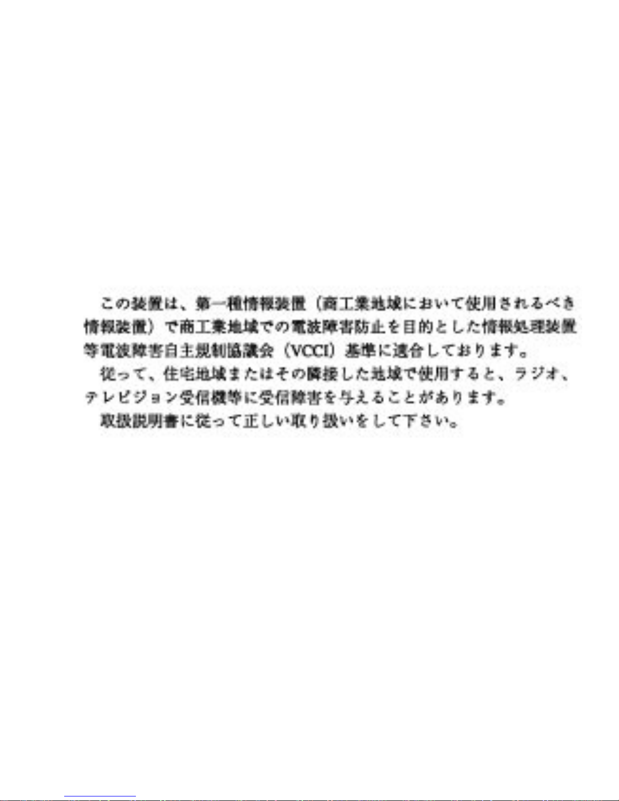
This equipment is in the 1st Class Category (information equipment to
be used in commercial and/or industrial areas) and conforms to the standards set by the Voluntary Control Council for Interference by Information Technology Equipment (VCCI) aimed at preventing radio
interference in commercial and/or industrial areas.
Consequently, when used in a residential area or in an adjacent area
thereto, radio interference may be caused to radios and TV receivers,
etc.
Read the instructions for correct handling
.
ST-500 INSTALLATION GUIDE iii
Page 5

TABLE OF CONTENTS
CHAPTER 1 INTRODUCTION
1.1 ST-500 Features............................................................................1-1
1.1.1 LANVIEW LEDs.............................................................1-3
1.1.2 Heartbeat (SQE) Test....................................................1-3
1.2 Getting Help...................................................................................1-4
CHAPTER 2 INSTALLATION
2.1 Unpacking the ST-500 Transceiver................................................2-1
2.2 Items Needed to Install the ST-500 Transceiver............................2-1
2.3 Installation Site...............................................................................2-2
2.4 Setting the SQE (Heartbeat Test ) Switch......................................2-2
2.5 Installing the Transceiver Tap........................................................2-3
2.5.1 Installing the ST-500-01 Transceiver Tap......................2-3
2.5.2 Installing the ST-500-02 or -03 Transceiver Tap ...........2-8
2.6 Connecting the Transceiver to the Host.......................................2-11
2.7 Checking the Installation..............................................................2-12
CHAPTER 3 TROUBLESHOOTING
3.1 LANVIEW LEDs.............................................................................3-1
3.2 Troubleshooting .............................................................................3-1
APPENDIX A ST-500 TRANSCEIVER SPECIFICATIONS
A.1 Receiver Specification............................................................... A-1
A.2 Transmitter Specification........................................................... A-1
A.3 Collision Detector Specification................................................. A-2
A.4 Power Specification................................................................... A-3
A.5 Interface Connector Pinout Identification.................................. A-4
A.6 Environmental Specifications.................................................... A-5
A.7 Service Specification................................................................. A-6
A.8 Physical Specification ............................................................... A-6
ST-500 INSTALLATION GUIDE v
Page 6

CHAPTER 1
INTRODUCTION
Welcome to the Cabletron Systems’ ST-500 Ethernet/IEEE 802.3
Transceiver with LANVIEW Installation Guide. This guide provides in-
stallers and service technicians with information required to install and,
if necessary, diagnose network problems.
Prior to installing and operating the ST-500 transceiver, read through
this manual completely to become familiar with its content and to gain an
understanding of the ST-500 features. A general working knowledge of
Ethernet/802.3 networks is helpful when installing the transceiver. Detailed specifications are contained in Appendix A.
1.1 ST-500 Features
Cabletron System’s ST-500 Ethernet/IEEE 802.3 Transceiver with LANVIEW provides a method of connecting to an Ethernet or IEEE 802.3
controller via a host compatible transceiver cable. The ST-500 transceiver is compatible with Ethernet Version 1.0 specifications (September
1980), Ethernet Version 2.0 specifications (November 1983), and IEEE
802.3 standard (1983) for a 10-Mbps Medium Access Unit (MAU).
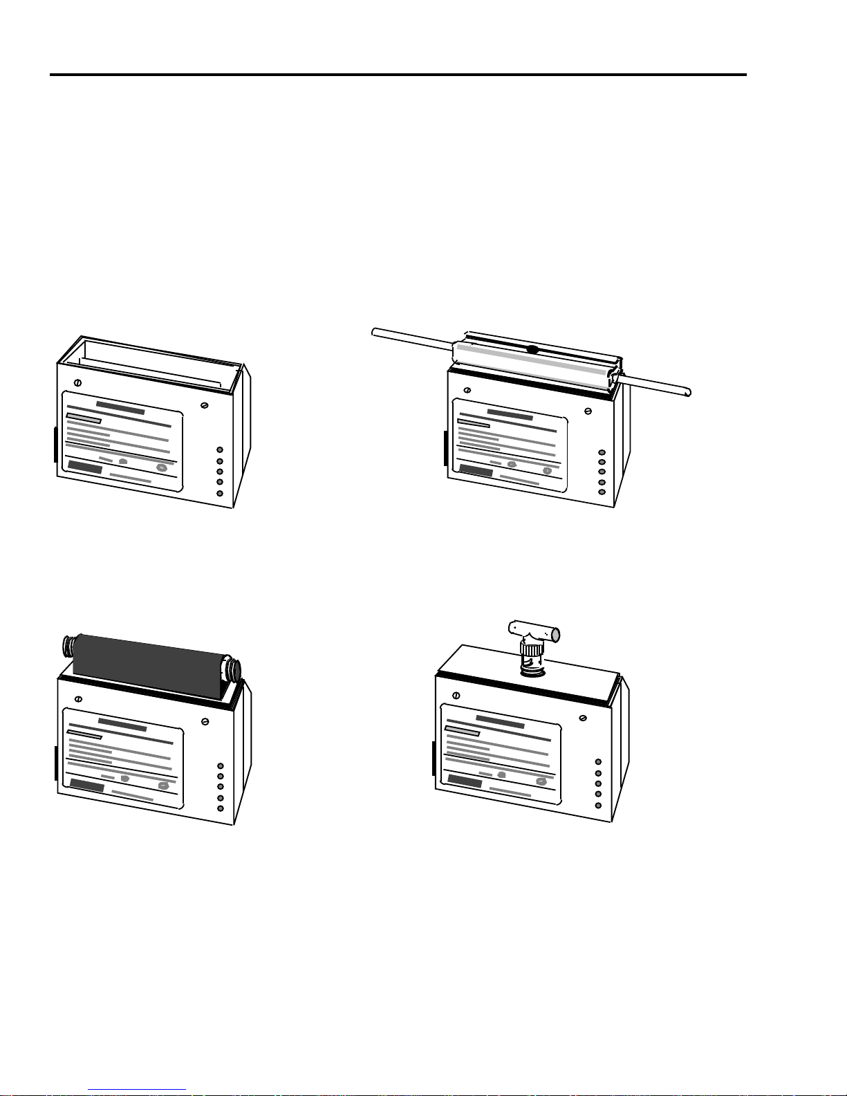
The ST-500 transceiver consists of two major components; a transceiver
body, and a tap. The type of media used in the network determines the
style of tap to install on the transceiver body (see Figure 1-1).
ST-500 INSTALLATION GUIDE Page 1-1
Page 7
CHAPTER 1:
INTRODUCTION
The type of tap provided with the transceiver body defines one of four
models of the ST-500 transceiver. The four models are:
•
•
•
•
ST-500-00
ST-500-01
ST-500-02
ST-500-03
PWR
SQE
XMT
RCV
CLN
- transceiver body only (no tap included)
- with non-intrusive (stinger style) Ethernet tap
- with N-Series (intrusive) Ethernet tap
- with BNC (Thin-net) tap
ST-500-00 TRANSCEIVER
WITHOUT TAP
PWR
SQE
XMT
RCV
CLN
ST-500-01 TRANSCEIVER WITH
NON-INTRUSIVE ETHERNET TAP
PWR
SQE
XMT
RCV
CLN
ST-500-02 TRANSCEIVER WITH N-SERIES
INTRUSIVE ETHERNET TAP
Figure 1-1. ST-500 Transceiver Models
Page 1-2 ST-500 INSTALLATION GUIDE
PWR
SQE
XMT
RCV
CLN
ST-500-03 TRANSCEIVER WITH
BNC THIN-NET TAP
Page 8

ST-500 Features
1.1.1 LANVIEW LEDs
The ST-500 transceiver has five LANVIEW LEDs that monitor network
activity (transmit, receive and collision present), power status, and heartbeat (SQE) test status. These LEDs are described in Table 1-1. They
serve as a useful tool to quickly diagnose physical layer problems.
Table 1-1. LANVIEW LEDs
LED DESCRIPTION
PWR Power - On when the transceiver is receiving power
from the attached node.
SQE Signal Quality Error Test - On if the Heartbeat (SQE)
test is enabled.
XMT Transmit - On during the transmission of packets from
the host.
RCV Receive - On to indicate traffic on the network.
CLN Collision Present - On when a collision is detected by
the transceiver.
1.1.2 Heartbeat (SQE) Test
The ST-500 transceiver supports the Heartbeat (SQE) test. An internal
switch is provided to enable or disable the heartbeat (SQE) test. The signal quality error (SQE) feature is used by some hosts to verify collision
signal path.
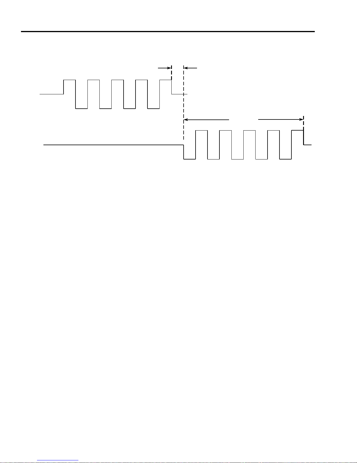
When the SQE test is enabled, the transceiver sends a 10-MHz burst on
the collision lead after transmissions. The burst must begin between 600
and 1600 ns after the end of the packet and must last for 500 to 1500 ns
(see Figure 1-2). The times are measured at the transceiver connector.
There is no collision test signal when just receiving.
ST-500 INSTALLATION GUIDE Page 1-3
Page 9
CHAPTER 1:
TRANSMIT
COLLISION
INTRODUCTION
600 ns TO
1600 ns
500 ns TO
1500 ns
Figure 1-2. Collision Test Signal Timing
1.2 Getting Help
If there is any additional support needed for the ST-500 transceiver or if
there are any questions, comments, or suggestions related to this manual, contact Cabletron Systems Technical Support:
By Phone: (603) 332-9400
Monday through Friday; 8 A.M. to 8 P.M. EST
By CompuServe: GO CTRON from any ! prompt
By Internet mail: [email protected]
Page 1-4 ST-500 INSTALLATION GUIDE
Page 10

CHAPTER 2
INSTALLATION
This chapter provides instructions for installing the three types of taps
supported by the ST-500 transceiver (see Figure 1-1). After unpacking
the transceiver and configuring the Heartbeat (SQE) test switch, perform
the tap installation procedure that is applicable to the transceiver model.
2.1 Unpacking the ST-500 Transceiver
Open the package containing the ST-500 transceiver and check its contents:
• 1 ST-500 transceiver body
• 2 Flat-head screws for attaching tap to transceiver
• 1 Cabletron Tap Kit (1K-TAP-01, 02, or 03)
• 1 Cabletron 1K-500 Installation Kit (for ST-500-01 only)
• 1 Installation guide
Inspect the ST-500 transceiver for damage. If it is damaged, contact
Cabletron Systems’ Customer Service. Save the shipping materials for
possible future shipment of the transceiver.
Note:
Taps may be installed and capped for future use. If extra taps are
required, the type of tap need only be called out. (Tap-01, Tap-02,
Tap-03)
2.2 Items Needed to Install the ST-500 Transceiver
To install the transceiver, the following items are needed:
• Cabletron Tap Kit
• Small flat-blade screw driver
• Cabletron 1K-500 Installation Kit (for ST-500-01 only, includes a
coring tool)
ST-500 INSTALLATION GUIDE Page 2-1
Page 11
CHAPTER 2:
INSTALLATION
2.3 Installation Site
To install the ST-500 transceiver, a minimum area of 17.8-cm (7-in) high
by 20.3-cm (8-in) wide by 10.2-cm (4-in) deep is recommended to provide enough space for the transceiver, tap, and Attachment Unit Interface (AUI) cable connections.
Ensure that the installation site meets the environmental conditions
specified in Appendix A.
2.4 Setting the SQE (Heartbeat Test ) Switch
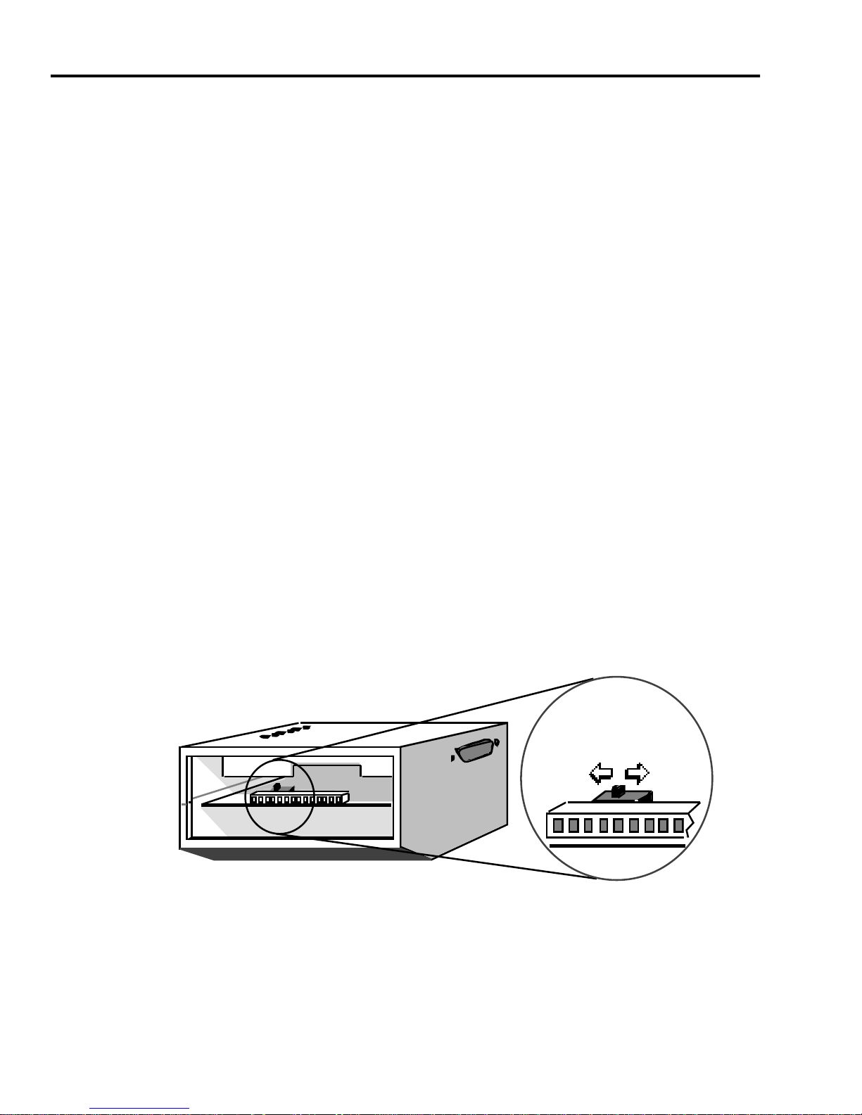
If the tap is already installed on the transceiver, remove the two flat-head
screws securing the tap to the transceiver case. Then remove the tap to
gain access to the SQE switch. Refer to Figure 2-1 for the location of the
SQE switch and how to set it to enable (ON) or disable (OFF) the heartbeat test feature.
Note:
The ST-500 transceiver is shipped with the SQE switch ON.
Ensure that the SQE switch is OFF whenever connecting the transceiver
to a repeater AUI. Otherwise, network problems (excess collisions) will
result.
SQE
SWITCH
ON
OFF
Figure 2-1. SQE Switch
Page 2-2 ST-500 INSTALLATION GUIDE
Page 12

Installing the Transceiver Tap
Once the power is on at the host system, the SQE LED will be lit on each
transceiver that has the heartbeat feature enabled. Conversely, the LED
is not lit on the transceivers with the heartbeat disabled.
Caution:
not
install a jumper to enable SQE. Damage can result if a jumper is
Earlier transceiver models used a jumper for this setting.
Do
installed in a transceiver equipped with an SQE switch.
2.5 Installing the Transceiver Tap
There are three types of taps that can be installed in the transceiver. To
install the transceiver tap, proceed to the appropriate transceiver tap installation instructions, as follows:
• For ST-500-01 transceivers, go to Section 2.5.1.
• For ST-500-02 and ST-500-03 transceivers, go to
Section 2.5.2.
2.5.1 Installing the ST-500-01 Transceiver Tap
To install the tap, proceed as follows:
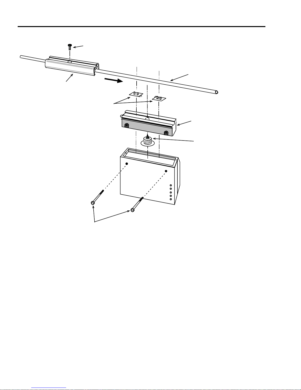
1. Open the 1K-TAP-01, Installation Kit (Figure 2-2) and check that it
contains the following:
• Cable Bed • Center Probe
• Clamp • Pressure Screw
• Braid picks (2) • Hex Wrench
ST-500 INSTALLATION GUIDE Page 2-3
Page 13
CHAPTER 2:
CLAMP SECTION
INSTALLATION
PRESSURE SCREW
BRAID
PICKS
ETHERNET
COAXIAL
CABLE
CABLE BED
SECTION
CENTER PROBE
PWR
SQE
XMT
RCV
CLN
FLAT-HEAD
SCREWS
Figure 2-2. Non-Intrusive Tap Kit
Page 2-4 ST-500 INSTALLATION GUIDE
Page 14
Installing the Transceiver Tap
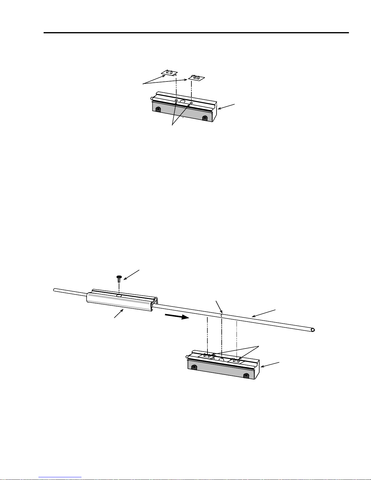
2. Insert the braid picks into the holes in the cable bed as shown in
Figure 2-3.
BRAID
PICKS
CABLE BED
SECTION
HOLES
Figure 2-3. Installing the Braid Picks
3. Determine the location for the tap on the coaxial cable. (Some
cables are marked at 2.5-meter (8.2-feet) intervals to indicate tap
locations.) Position the cable over the braid picks in the cable bed
section (see Figure 2-4). Slide the clamp into the guide slots on
the cable bed.
4. Thread the pressure screw into the top of the clamp and tighten it
using the hex wrench supplied in the tap kit.
PRESSURE SCREW
2.5-METER CABLE
MARKING
CLAMP SECTION
ETHERNET
COAXIAL
CABLE
BRAID
PICKS
CABLE BED
SECTION
Figure 2-4. Installing the Cable Clamp
ST-500 INSTALLATION GUIDE Page 2-5
Page 15
CHAPTER 2:
INSTALLATION
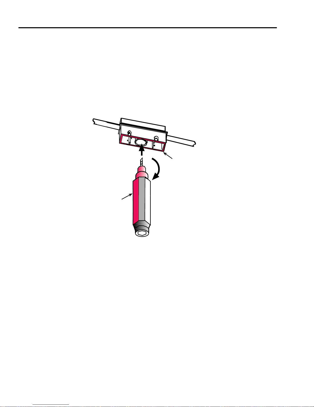
5. Drill a hole in the cable for the center probe. Insert the drill end of
the hand coring tool into the center hole and apply pressure while
twisting the coring tool clockwise (see Figure 2-5). When the
coring tool turns freely, remove the coring tool. (The coring tool
has a stop to prevent over-drilling.) Remove debris by holding the
tap with the cable bed facing down and tapping lightly on the side
of the tap. Do not blow into the hole to remove debris. Examine the
hole to be sure that it is free of debris.
CABLE
BED
CORING
TOOL
Figure 2-5. Drilling the Ethernet Cable
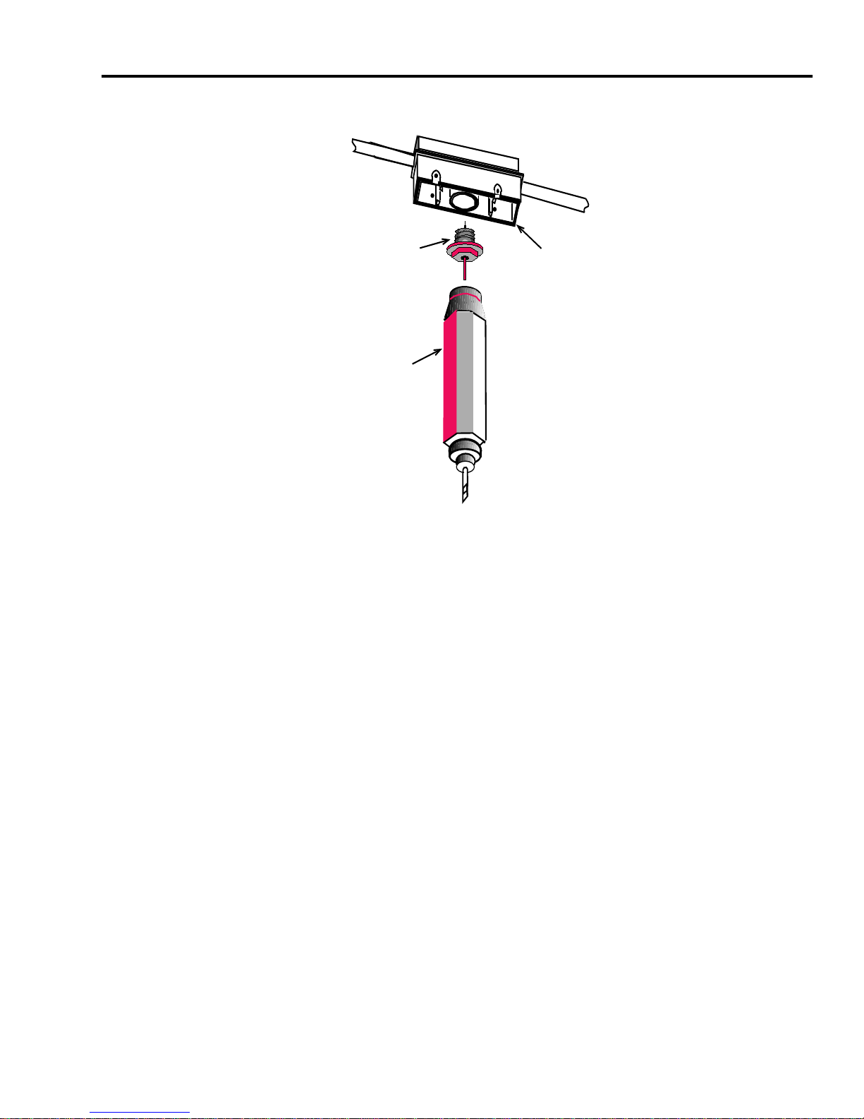
6. Install the center probe using the nut driver end of the coring tool
(see Figure 2-6). Insert the center probe into the hole in the
underside of the cable bed and tighten until snug.
Page 2-6 ST-500 INSTALLATION GUIDE
Page 16
CENTER
PROBE
CORING
TOOL
Installing the Transceiver Tap
CABLE
BED
Figure 2-6. Installing the Center Probe
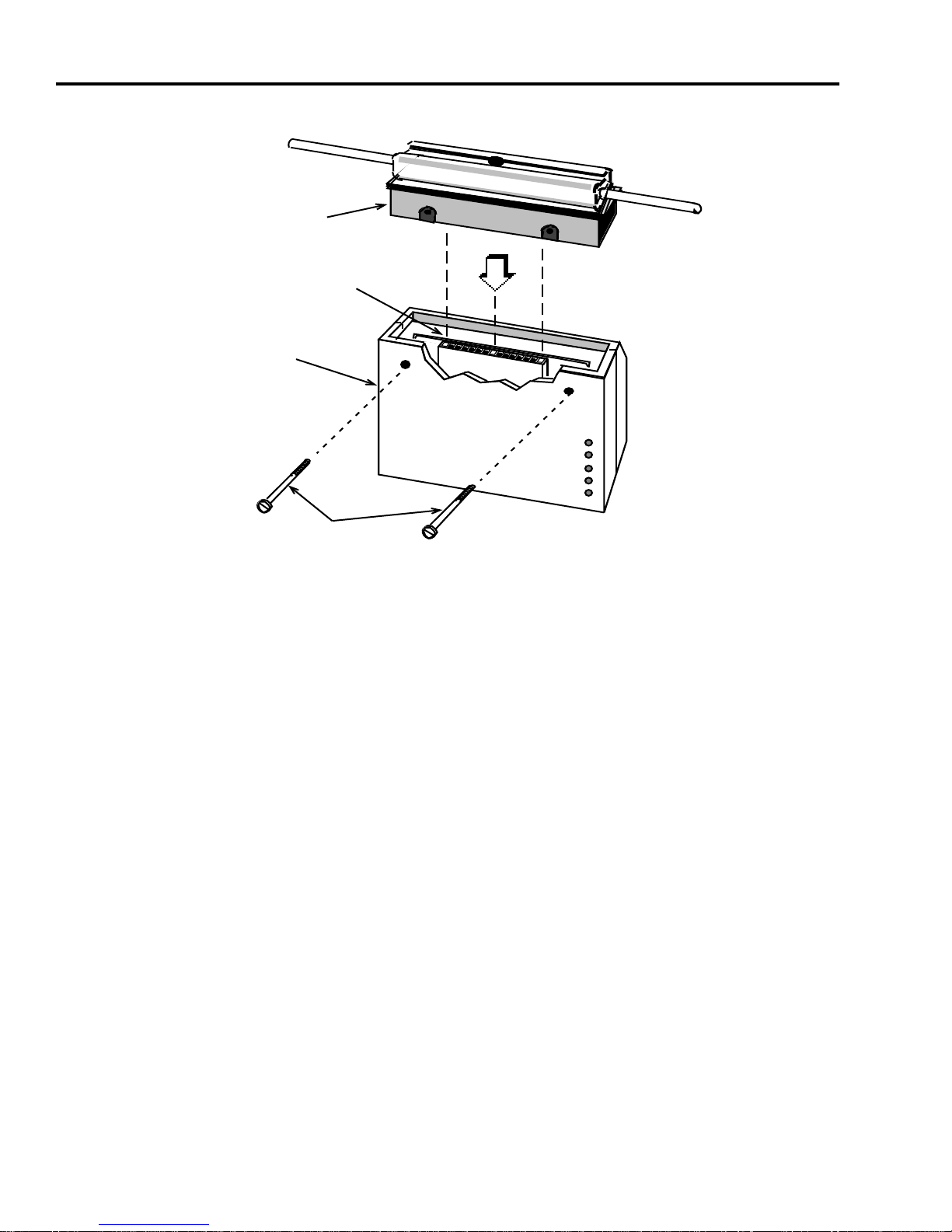
7. With the center probe installed, the transceiver case can be
attached to the tap. Remove the two flat-head screws from the
transceiver case and insert the tap into the rectangular opening in
the case. Make sure the tap pins are aligned with the connector
block on the transceiver circuit board.
Caution:
Avoid forcing the tap into the case. Very little force is needed.
If the tap does not seat easily, remove it to determine the cause of the
obstruction.
8. Insert and tighten the flat-head screws shown in Figure 2-7.
ST-500 INSTALLATION GUIDE Page 2-7
Page 17
CHAPTER 2:
INSTALLATION
TAP
ASSEMBL Y
CONNECTOR
BLOCK
TRANSCEIVER
CASE
PWR
SQE
XMT
RCV
CLN
FLA T-HEAD
SCREWS
Figure 2-7. Installing the Tap
9. Check the tap using an ohmmeter. The dc resistance between the
center probe and the braid should read approximately 25 ohms.
For more comprehensive testing of the transceiver and transceiver
tap, use a Cabletron Systems LAN-MD Transceiver and Cable
Tester.
10. The transceiver is now ready to be connected to the host system
cable. Proceed to Section 2.6.
2.5.2 Installing the ST-500-02 or -03 Transceiver Tap
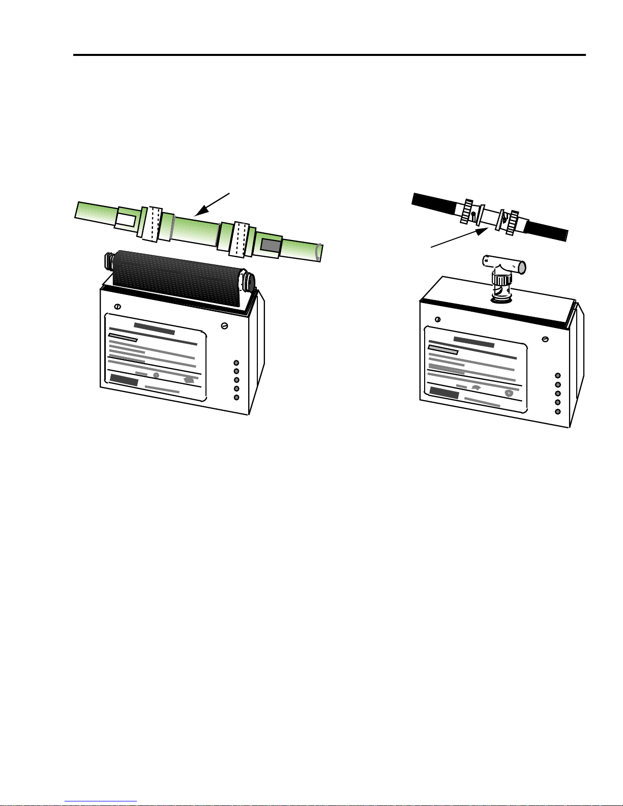
The ST-500-02 and ST-500-03 transceivers are installed in series with
the network cable. As shown in Figure 2-8, the ST-500-02 transceiver
has a tap with two male N-series connectors for network cable
connections, while the ST-500-03 has a tap with a BNC and T-connector
to make the cable connections. Both connections are intrusive taps that
Page 2-8 ST-500 INSTALLATION GUIDE
Page 18
Installing the Transceiver Tap
require cutting the network cable and installing male-mating connectors
to attach the transceiver. A barrel (female to female) connector is used
to provide network cable continuity when the transceiver is not installed.
.
N-SERIES FEMALE-TO-FEMALE
BARREL CONNECTOR
BNC FEMALE-TO-FEMALE
BARREL CONNECTOR
PWR
SQE
XMT
RCV
CLN
ST-500-2 TRANSCEIVER WITH N-SERIES
(INTRUSIVE) ETHERNET TAP
ST-500-3 TRANSCEIVER WITH
BNC THIN-NET TAP
PWR
SQE
XMT
RCV
CLN
Figure 2-8. N-Series and BNC Taps
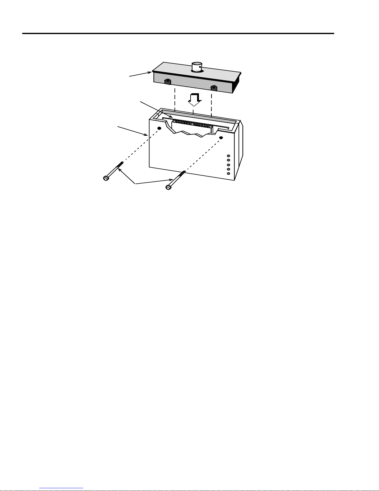
If the tap is already installed on the transceiver body, go to step 3. Otherwise, proceed as follows:
1. Remove the two flat-head screws from the transceiver case and
insert the tap into the rectangular opening in the case (see
Figure 2-9). Make sure the tap pins are aligned with the connector
block on the transceiver circuit board.
Caution:
Avoid forcing the tap into the case. Very little pressure is
needed. If the tap does not seat easily, remove the tap and examine the
tap and connector block for obstructions.
ST-500 INSTALLATION GUIDE Page 2-9
Page 19
CHAPTER 2:
INSTALLATION
TAP
ASSEMBLY
CONNECTOR
BLOCK
TRANSCEIVER
CASE
FLAT-HEAD
SCREWS
PWR
SQE
XMT
RCV
CLN
Figure 2-9. Installing the Tap
2. Insert and tighten the flat-head screws (see Figure 2-9).
3. Test the transceiver and transceiver tap using a Cabletron
Systems LAN-MD Transceiver and Cable Tester.
4. Select a location for the transceiver and note the following:
a. If a barrel connector is not installed at the location where the
transceiver will be attached, the cable must be cut and BNC
or N-series connectors, as applicable, must be installed by a
qualified technician.
b. If a barrel connector is installed at the location for the
transceiver, remove the barrel connector and install the
transceiver in its place.
Note:
If the transceiver is the last device on the network cable, connect
a terminator to the open end of the T-connector.
5. The transceiver is now ready to connect to the host system cable.
Proceed to Section 2.6.
Page 2-10 ST-500 INSTALLATION GUIDE
Page 20
Connecting the Transceiver to the Host
2.6 Connecting the Transceiver to the Host
The ST-500 Transceiver is designed to operate with Ethernet Version
1.0, Version 2.0, and IEEE 802.3 compliant systems. However, each
version requires different wiring for the transceiver cable. Since cable
grounding is accomplished at the host end of the cable, the correct cable
must be used according to the requirements of the host equipment.
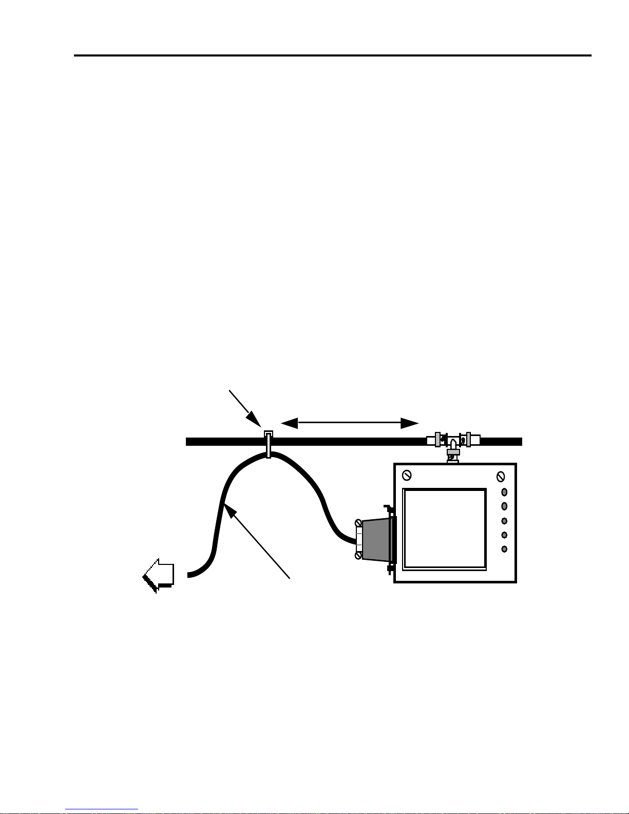
1. Plug the female end of the transceiver cable into the 15-pin
connector on the side of the transceiver and slide the connector
lock to secure the connector.
2. Use a tie-wrap to fasten the transceiver cable to the Ethernet
cable (see Figure 2-10). This provides a strain relief for the
transceiver cable connection.
3. Attach the male end of the cable to the 15-pin connector on the
host system.
TIE-WRAP
APPROXIMATELY
6 INCHES
TO HOST
AUI PORT
TRANSCEIVER
(AUI) CABLE
Figure 2-10. Attaching the Transceiver Cable
ST-500 INSTALLATION GUIDE Page 2-11
Page 21

CHAPTER 2:
INSTALLATION
2.7 Checking the Installation
Power up the host system. The LANVIEW LEDs on the transceiver indicate normal operation as described in Table 2-1.
Table 2-1. LANVIEW LEDs, Normal Operation
LANVIEW LED SQE Enabled SQE Disabled
Power LED
SQE
Transmit
Receive
Collision
On On
On Off
On during host
transmissions
Flashes to indicate
network traffic
On for collisions on
the network and
On during host
transmissions
Flashes to indicate
network traffic
On for collisions
on the network
host transmissions
If the LANVIEW LEDs do not indicate normal operation, refer to
Chapter 3 for troubleshooting information.
Page 2-12 ST-500 INSTALLATION GUIDE
Page 22

CHAPTER 3
TROUBLESHOOTING
This chapter provides troubleshooting information based on the condition of the LANVIEW LEDs on the transceiver. The troubleshooting information consists of some of the most common potential problems and
solutions. If a problem persists after performing the recommended corrective actions, contact Cabletron Systems Technical Support.
3.1 LANVIEW LEDs
The condition of the LANVIEW LEDs provides valuable troubleshooting
information about how the system is operating. Refer to Chapter 2,
Table 2-1, for the LANVIEW LED conditions that indicate normal operation. If the LANVIEW LEDs do not indicate normal operation, proceed to
the next section, Troubleshooting.
3.2 Troubleshooting
The conditions described in Table 3-1 apply only when a host system is
attached and transmitting data packets. Two Ethernet testers, such as
the Cabletron Systems LAN Specialist network monitoring device, can
be used to exchange data packets and provide more comprehensive
testing.
Observe the LANVIEW LEDs on more than one transceiver to determine
if the problem is with an individual node or if it is common to the network.
When similar indications appear at more than one station, the problem
is most likely a network problem. If the symptoms are observed at only
one station, chances are the problem is with that node.
Note:
SQE enabled and off with SQE disabled. If, after setting the SQE
configuration, the LED does not indicate the proper setting, the problem
is in the transceiver.
The SQE LED is not discussed here, since the SQE LED is on with
ST-500 INSTALLATION GUIDE Page 3-1
Page 23

CHAPTER 3:
TROUBLESHOOTING
Table 3-1 lists the more common error conditions displayed on the LANVIEW LEDs along with the probable cause and recommended corrective
action.
Table 3-1. Troubleshooting Guide
Probable Cause Corrective Action
Condition 1
1. Transceiver cable is discon-
- No LANVIEW LEDs lit
Connect the transceiver cable.
nected.
2. Host powered-off. Turn on power to the host.
Condition 2
-
PWR
on,
XMT
and
RCV
off, and
CLN
on steadily
1. Open tap. Ensure that the tap was
installed into the transceiver
body without bending the center
probe that plugs into the connector block on the transceiver
circuit board.
Ensure that the depth of the
center probe hole is correct (drill
Coaxial cable not terminated. Ensure that all coaxial cables
Page 3-2 ST-500 INSTALLATION GUIDE
the hole again if necessary).
are properly terminated.
Page 24

Troubleshooting
Table 3-1. Troubleshooting Guide (Cont’d)
Probable Cause Corrective Action
Condition 3
Note:
This is a normal condition if SQE is enabled and the host is
-
PWR
on,
XMT, RCV
transmitting.
1. Intermittent tap connection or
open coaxial cable.
2. Wrong transceiver cable
installed.
Condition 4
-
PWR
on,
XMT
flashing,
, and
CLN
on (simultaneously).
Check other stations for the
same condition.
Check the transceiver tap installation.
Check for improperly terminated
or cut cable.
Check cable wiring (V1.0, V2.0,
or IEEE 802.3).
RCV
and
CLN
off
1. Transceiver tap or coax
cable is shorted.
Condition 5
CLN
on steady.
-
PWR
on,
XMT
1. Collision path via transceiver cable is broken. Collision is not being recognized
by the controller.
flashing,
Check for and remove any
debris in the center probe hole.
RCV
on/flashing or off, and
Examine the transceiver cable
for damage. Replace it if necessary.
ST-500 INSTALLATION GUIDE Page 3-3
Page 25

APPENDIX A
ST -500 TRANSCEIVER SPECIFICA TIONS
This appendix provides the specifications for the ST-500 Transceiver.
A.1 Receiver Specification
Item T ypical Value Wor st Case
Leakage Current: 0 µA -0.5 to +0.5 µA
Input Impedance: >3.8 MΩ >1.9 MΩ
Coax Cable Tap Capacitance: 3.7 pF 3.9 pF
Delay Time (Input to Output):
Turn-On
Steady-State
DI Rise/Fall Time: 2.8 ns 4.0 ns
DI Output Voltage: +/- 855 mV +/- 810 to +/- 920 mV
180 ns
11.2 ns
300 ns
19.0 ns
A.2 Transmitter Specification
Item
Output Current:
AC Component
DC Component
Waveform Symmetry: - 0.5 ns - 1.1 to +0.4 ns
Typical
Value
+ /-38 mA
-40 mA
Worst Case
+/-39 to +/-40 mA
-39 to -42 mA
ST-500 INSTALLATION GUIDE Page A-1
Page 26

APPENDIX A: ST-500 TRANSCEIVER SPECIFICATIONS
Item
Delay Time (Input to Output):
Start-Up
Steady-State
Signal Spectrum Harmonic:
Second and Third
Fourth and Fifth
Sixth and Seventh
Higher
Input Impedance:
Differential
Common-mode
Frequency Range:
Common-mode
Typical
Value
150 ns
26.9 ns
-24.2 dB
-35.7 dB
-56.3 dB
-55.4 dB
80.3 Ω
> 20.0 Ω
2 to 30 MHz
Worst Case
175 ns
30.1 ns
-19.3 dB
-32.0 dB
-48.3 dB
-52.3 dB
79.4 to 81.0 Ω
2 to 30 MHz
Voltage Range
at Input
0 to 30 Volts
0 to 5 Volts
Differential Input
Voltage Required for
Operation: +/- 90 mV +/- 150 mV
A.3 Collision Detector Specification
Item
Turn-On Delay: 806 ns 691 to 864 ns
Output Frequency: 10.2 MHz 9.5 to10.8 MHz
Turn-Off Delay: 500 ns 2000 ns
Typical
Worst Case
Value
Page A-2 ST-500 INSTALLATION GUIDE
Page 27

Power Specification
Item
Worst Case
Value
Collision DC Threshold: -1566 mV -1510 to 1591 mV
Interframe Test Signal (optional):
Typical
Delay
Duration
800 ns
752 ns
731 to 864 ns
709 to 812 ns
Output Voltage: +/- 855 mV +/- 790 to
+/- 930 mV
Jabber Control:
Time-out
Reset Time
28.8 ms
400 ms
26.7 to 29.6 ms
400 to 600 ms
A.4 Power Specification
Item
Worst Case
Value
Input Voltage: 12 Vdc 9.5 to 15.75 Vdc
Current: 278 mA 448 mA
Typical
ST-500 INSTALLATION GUIDE Page A-3
Page 28

APPENDIX A: ST-500 TRANSCEIVER SPECIFICATIONS
A.5 Interface Connector Pinout Identification
Pin Description Pin Description
1 Logic Ref. 9 Collision –
2 Collision + 10 Transmit –
3 Transmit + 11 Logic Ref.
4 Logic Ref. 12 Receive –
5 Receive + 13 Power (+12 Vdc)
6 Power return 14 Logic Ref.
7 N/C 15 N/C
8 Logic Ref.
Note: The shell is connected to the cable shield and case.
The ST-500 transceiver is compliant with the IEEE 802.3 standard and
compatible with Ethernet versions 1.0 and 2.0. However, the AUI cable
used to connect a device to the ST-500 transceiver is dependent on the
Ethernet version of that device. The cable wiring configurations according to IEEE 802.3 and Ethernet versions 1.0 and 2.0 are as follows:
Ethernet V1.0
(3) 22 AWG pairs. (1) 20 AWG Inner & Outer shield common at the connector shell and Pin 1.
Ethernet V2.0
(4) 20 AWG pairs, Inner & Outer shield common at the connector shell
and Pin 1.
IEEE 802.3
(4) 20 AWG pairs, Inner & Outer shield isolated from each other. Outer
shield connected to the connector shell and Pin 1.
Page A-4 ST-500 INSTALLATION GUIDE
Page 29

Environmental Specifications
A.6 Environmental Specifications
Non-Operating Temperature: -20° C (-4° F) to
+90° C (194° F)
Operating Temperature: 5° C (40° F) to
40°C (104° F)
Operation Humidity: 5 to 95% non-condensing
Note: The ST-500 transceiver meets all federal, state, and city standards for use in air plenums.
Electromagnetic Susceptibility:
Operates properly in the following externally applied fields:
10 kHz to 30 MHz 2 Volts/meter
30 MHz to 1000 MHz 5 Volts/meter
Operates properly with a 1 V/ns slope transient applied from the
coax shield to the transceiver case.
Electromagnetic Radiation:
Meets FCC part 15, Class A and B limits.
Caution: It is the responsibility of the person who sells the system that
includes the ST-500 transceiver to ensure that the total system
complies with the allowable limits of conducted and radiated
emissions.
Isolation:
1000 Vac, 50/60 Hz applied between the shield of coaxial cable
and the shield of the transceiver cable or transceiver case.
ST-500 INSTALLATION GUIDE Page A-5
Page 30

APPENDIX A: ST-500 TRANSCEIVER SPECIFICATIONS
A.7 Service Specification
MTBF (MHBK-217D): 652,315 hrs. (calculated)
MTTR: <.25 hr.
A.8 Physical Specification
The following dimensions and weight are for the transceiver (ST-500-00)
without the optional tap.
Height: 7.0 cm (2.75 in)
Width: 8.8 cm (3.46 in)
Depth: 4.5 cm (1.77 in)
Weight: 280 g (10 oz)
Page A-6 ST-500 INSTALLATION GUIDE
 Loading...