

Cabletron Systems SSR-ATM29-02, SSR-GLX19-02, SSR-GLX70-01, SSR-GSX11-02, SSR-HFX11-08 User Manual
...Page 1

CoreWatch User’s Guide
9032564
Page 2

Page 3

Notice
Notice
Cabletron Systems reserves the right to make changes in specifications and other information contained
in this document without prior notice. The reader should in all cases consult Cabletron Systems to
determine whether any such changes have been made.
The hardware, firmware, or software described in this manual is subject to change without notice.
IN NO EVENT SHALL CABLETRON SYSTEMS BE LIABLE FOR ANY INCIDENTAL,
INDIRECT, SPECIAL, OR CONSEQUENTIAL DAMAGES WHATSOEVER (INCLUDING BUT
NOT LIMITED TO LOST PROFITS) ARISING OUT OF OR RELATED TO THIS MANUAL OR
THE INFORMATION CONTAINED IN IT, EVEN IF CABLETRON SYSTEMS HAS BEEN
ADVISED OF, KNOWN, OR SHOULD HAVE KNOWN, THE POSSIBILITY OF SUCH
DAMAGES.
© Copyright April 1998 by:
Cabletron Systems, Inc.
35 Industrial Way
Rochester, NH 03867-5005
All Rights Reserved
Printed in the United States of America
Order Number: 9032564
LANVIEW is a registered trademark, and SmartSwitch is a trademark of
Cabletron Systems, Inc.
CompuServe is a registered trademark of CompuServe, Inc.
i960 microprocessor is a registered trademark of Intel Corp.
Ethernet is a trademark of Xerox Corporation.
iii
Page 4

Notice
FCC Notice
This device complies with Part 15 of the FCC rules. Operation is subject to the following two
conditions: (1) this device may not cause harmful interference, and (2) this device must accept any
interference received, including interference that may cause undesired operation.
NOTE: This equipment has been tested and found to comply with the limits for a Class A digital
device, pursuant to P art 1 5 of the FCC r ules. These limits are design ed to provide reasonable protection
against harmful interference when the equipment is operated in a commercial environment. This
equipment uses, generates, and can radiate radio frequency energy and if not installed in accordance
with the operator’s manual, may cause harmful interference to radio communications. Operation of this
equipment in a residential area is likely to cause interference in which case the user will be required to
correct the interference at his own expense.
WARNING: Changes or modifications made to this device which are not expressly approved by the
party responsible for compliance could void the user’s authority to operate the equipment.
VCCI Notice
This is a Class A product based on the standard of the Voluntary Control Council for Interference by
Information Technology Equipment (VCCI). If this equipment is used in a domestic environment, radio
disturbance may arise. When such trouble occurs, the user may be required to take corrective actions.
DOC Notice
This digital apparatus does not exceed the Class A limits for radio noise emissions from digital
apparatus set out in the Radio Interference Regulations of the Canadian Department of
Communications.
Le présent appareil numérique n’émet pas de bruits radioélectriques dépassant les limites applicables
aux appareils numériques de la class A prescrites dans le Règlement sur le br ouillage radioélectrique
édicté par le ministère des Communicati o ns du Canada.
iv
Page 5

DECLARATION OF CONFORMITY
ADDENDUM
Application of Council Directive(s): 89/336/EEC
73/23/EEC
Manufacturer’s Name: Cabletron Systems, Inc.
Manufacturer’s Address: 35 Industrial Way
PO Box 5005
Rochester, NH 03867
European Representative Name: Mr. J. Solari
European Representative Address: Cabletron Systems Limited
Nexus House, Newbury
Business Park
London Road, Newbury
Berkshire RG13 2PZ, England
Notice
Conformance to Directive(s)/Product Standards:
EC Directive 89/336/EEC
EC Directive 73/23/EEC
EN 55022
EN 50082-1
EN 60950
Equipment Type/Environment: Networking Equipment, for
use in a Commercial or Light
Industrial Environment.
We the undersigned, hereby declare, under our sole responsibility, that the equipment
packaged with this notice conforms to the above directives.
Manufacturer Legal Representative in Europe
Mr. Ronald Fotino Mr. J. Solari
____________________________________________________ ____________________________________
Full Name Full Name
Principal Compliance Engineer Managing Director - E.M.E.A.
____________________________________________________ ____________________________________
Title Title
Rochester, NH, USA Newbury, Berkshire, England
____________________________________________________ ____________________________________
Location Location
v
Page 6

Notice
vi
Page 7

Contents
Preface..................................................................................................... 15
About This Guide...................................................................................................................15
Who Should Read This Manual? .........................................................................................15
How to Use This Guide.........................................................................................................15
Related Documentation.........................................................................................................17
Chapter 1: A Look at CoreWatch ........................................................... 19
What Are CoreWatch’s Features?........................................................................................19
System Requirements ............................................................................................................20
CoreWatch Capabilities.........................................................................................................20
A Look at the Modes of CoreWatch ....................................................................................21
Which MIBs Does the SSR Support? ...................................................................................21
Chapter 2: CoreWatch Installation ........................................................ 23
Installing CoreWatch.............................................................................................................23
Installing on a Solaris System........................................................................................23
Installing on a Windows NT or Windows 95 System................................................24
Chapter 3: Learning CoreWatch Basics.................................................. 25
Starting CoreWatch................................................................................................................25
Starting CoreWatch in Solaris.......................................................................................26
Starting CoreWatch in Windows NT or Windows 95...............................................26
Starting CoreWatch from within SPECTRUM Enterprise Manager .......................26
Starting CoreWatch from within HP OpenView 5.x .................................................27
A Look at the CoreWatch Interface .....................................................................................27
Front Panel View.............................................................................................................28
A Look at the Modules............................................................................................29
Schematic View ...............................................................................................................30
Opening the Schematic View.................................................................................30
Using the Schematic View......................................................................................31
CoreWatch Menus ..........................................................................................................31
CoreWatch Toolbar.........................................................................................................31
CoreWatch Passwords...........................................................................................................31
Changing the Login Password......................................................................................32
Changing the Privileged Password..............................................................................32
Accessing Help .......................................................................................................................33
Exiting CoreWatch.................................................................................................................34
CoreWatch Users Guide 7
Page 8

Contents
Chapter 4: Learning Configuration Expert Basics.................................35
What Is Configuration Expert?............................................................................................ 35
Starting Configuration Expert............................................................................................. 36
Opening Configuration Expert from the Front Panel View .................................... 36
Opening Configuration Expert from the Schematic View....................................... 37
A Look at the Configuration Expert Window................................................................... 38
Configuration Tree......................................................................................................... 39
Configuration Files ................................................................................................. 41
A Look at the Configuration Tree Icons .............................................................. 42
Wizards and Dialog Boxes............................................................................................ 42
Configuration Expert Toolbar...................................................................................... 43
Copying Objects..................................................................................................................... 43
Copying and Pasting an Object.................................................................................... 44
Dragging Objects to Copy Their Configuration Settings ......................................... 44
Finding Objects...................................................................................................................... 45
Deleting Objects..................................................................................................................... 45
Order of Configuration Tasks.............................................................................................. 45
Committing Your Configuration Changes........................................................................ 46
Discarding Your Configuration Settings ........................................................................... 48
Exiting Configuration Expert .............................................................................................. 48
Chapter 5: Changing System Settings ................................................... 49
Providing System Information............................................................................................ 49
Configuring Ports.................................................................................................................. 50
Configuring Global Settings on All Ports................................................................... 51
Configuring an Individual Port ................................................................................... 52
Configuring the SSR for a SYSLOG Server........................................................................ 56
Configuring for DNS ............................................................................................................ 58
Configuring the SSR for SNMP........................................................................................... 59
Setting Up a Target for SNMP Traps .......................................................................... 59
Establishing Community Strings................................................................................. 61
Chapter 6: Configuring SSR Bridging..................................................... 63
A Look at Bridging on the SSR............................................................................................ 63
Configuring the Bridging Mode of Ports........................................................................... 64
Configuring a Port for Flow-Based Bridging............................................................. 65
Configuring a Port for Address-Based Bridging....................................................... 66
Controlling the Aging State of SSR Bridging.................................................................... 68
Setting Up a Default Aging Timeout........................................................................... 68
Overriding the Default Timeout Interval on a Port.................................................. 69
Disabling Aging on a Port............................................................................................. 70
Enabling Aging on a Port.............................................................................................. 72
Setting Up STP on the SSR................................................................................................... 74
Defining STP Settings for SSR Bridging...................................................................... 75
Defining STP Attributes on an Individual Port......................................................... 76
Enabling STP on a Port.................................................................................................. 77
Disabling STP on a Port................................................................................................. 79
8 CoreWatch Users Guide
Page 9

Contents
Chapter 7: Configuring VLANs on the SSR............................................ 81
A Look at VLANs on the SSR...............................................................................................81
VLAN Configuration Tips....................................................................................................82
Defining Access Ports and Trunk Ports..............................................................................83
Creating a Protocol-Based VLAN........................................................................................85
Creating a Port-Based VLAN...............................................................................................90
Modifying VLANs .................................................................................................................94
Changing a Port-Based VLAN’s Name or ID.............................................................95
Changing a Protocol-Based VLAN’s Name, ID, or Protocol Binding.....................96
Replacing an Interface’s VLAN............................................................................................97
Changing Which Ports a VLAN Includes...........................................................................97
Dragging Ports to Add Them to a VLAN ...................................................................97
Adding and Removing a VLAN’s Ports Through a Dialog Box..............................98
Chapter 8: Configuring IP Interfaces for the SSR ............................... 101
What Is IP? ............................................................................................................................101
A Look at IP Addresses................................................................................................102
Creating IP Interfaces ..........................................................................................................103
Creating IP Interfaces Bound to a Single Port ..........................................................104
Creating IP Interfaces Bound to a VLAN..................................................................110
Modifying IP Interface Definitions....................................................................................115
What to Do Next...................................................................................................................118
Chapter 9: Configuring Unicast Routing on the SSR.......................... 119
Configuring Unicast Global Parameters and Static Entries...........................................119
Setting Global Parameters for Unicast Routing........................................................120
Defining Static ARP Entries.........................................................................................121
Defining Static Route Entries ......................................................................................123
A Look at RIP Routing in the IP Environment................................................................125
What Is Preference? ......................................................................................................126
Configuring the SSR for RIP...............................................................................................127
Setting RIP Global Parameters....................................................................................127
Defining IP RIP Interfaces............................................................................................129
Adding Trusted Gateways ..........................................................................................132
Adding Source Gateways ............................................................................................132
What to Do Next...................................................................................................................133
Chapter 10: Configuring Multicast Routing on the SSR..................... 135
What Is DVMRP? .................................................................................................................135
Configuring DVMRP Routing on the SSR........................................................................136
Setting DVMRP Global Parameters on the SSR........................................................137
Configuring DVMRP Interfaces..................................................................................138
Defining DVMRP Tunnels...........................................................................................139
Enabling or Disabling DVMRP on Tunnels..............................................................141
What Is IGMP?......................................................................................................................142
Configuring IGMP Interfaces on the SSR.........................................................................143
Setting IGMP Global Parameters................................................................................143
Enabling or Disabling IGMP on Interfaces ...............................................................144
What to Do Next...................................................................................................................146
CoreWatch Users Guide 9
Page 10

Contents
Chapter 11: Configuring the SSR for IPX Routes ................................ 147
What Is IPX?......................................................................................................................... 147
Creating IPX Interfaces....................................................................................................... 149
Creating IPX Interfaces Bound to a Single Port....................................................... 149
Creating IPX Interfaces Bound to a VLAN............................................................... 155
Modifying IPX Interface Definitions ................................................................................ 160
Configuring Static IPX SAP Entries.................................................................................. 163
What to Do Next.................................................................................................................. 166
Chapter 12: Configuring QoS on the SSR............................................ 167
What Is QoS?........................................................................................................................ 167
Establishing the SSR’s Queuing Policy ............................................................................ 168
Associating Precedences to Layer-3/Layer-4 Flows...................................................... 169
Assigning IP QoS Precedence............................................................................................ 169
Assigning IPX QoS Precedence.................................................................................. 171
Creating QoS Profiles.......................................................................................................... 172
Creating a QoS Profile for an IP Flow....................................................................... 173
Creating a QoS Profile for an IPX Flow .................................................................... 178
Creating a QoS Profile for a Layer-2 Flow................................................................ 183
Modifying QoS Profiles...................................................................................................... 187
Redefining an IP Flow ................................................................................................. 187
Redefining an IPX Flow Definition............................................................................ 188
Redefining a Layer-2 Flow Definition....................................................................... 189
Changing an IP or IPX Flow’s Interface List............................................................ 190
Adding or Deleting a Flow’s Interfaces through a Dialog Box...................... 191
Dragging an Interface to Apply a Flow to the Interface.................................. 192
Changing a Layer-2 Port List...................................................................................... 192
Chapter 13: Configuring Security on the SSR ..................................... 195
A Look at ACLs ................................................................................................................... 195
Setting IP Security ............................................................................................................... 196
Setting IPX Security............................................................................................................. 200
Configuring an IPX ACL............................................................................................. 200
Setting Up IPX RIP Filters........................................................................................... 205
Setting Up IPX SAP Filters.......................................................................................... 209
Applying ACLs to IP or IPX Interfaces............................................................................ 212
Copying an ACL to Apply It to an Interface............................................................ 213
Applying an ACL by Editing an Interface’s Definition.......................................... 214
Setting Layer-2 Security...................................................................................................... 216
Configuring Layer-2 Address Filters ........................................................................ 217
Configuring Layer-2 Port-to-Address Lock Filters................................................. 219
Configuring Layer-2 Static-Entry Filters .................................................................. 222
Configuring Layer-2 Secure Port Filters................................................................... 226
Modifying the SSR’s Security Settings ............................................................................. 229
Changing an ACL’s Name.......................................................................................... 230
Adding or Modifying ACL Rules.............................................................................. 231
Modifying Layer-2 Security Filters............................................................................ 231
Modifying a Filter’s Settings ............................................................................... 231
Modifying a Filter’s Port Bindings ..................................................................... 232
10 CoreWatch Users Guide
Page 11

Contents
Chapter 14: Configuring OSPF on the SSR.......................................... 235
Setting OSPF Global Parameters........................................................................................235
Configuring OSPF Area Tables...................................................................................236
Creating OSPF Area Tables..................................................................................237
Modifying Area Tables .........................................................................................253
Chapter 15: Checking System Status................................................... 255
Obtaining Chassis Information..........................................................................................255
Obtaining Port Information................................................................................................256
Chapter 16: Monitoring Real-Time Performance................................ 259
Monitoring System Performance.......................................................................................259
Setting the Scaling of Dials..........................................................................................261
Monitoring Port Utilization................................................................................................262
Obtaining Statistics About an Individual Port.................................................................264
Obtaining Packet Statistics ..........................................................................................265
Obtaining Port Byte Statistics......................................................................................266
Obtaining Port Error Statistics ....................................................................................267
Monitoring IP Interface Statistics.......................................................................................269
Obtaining IP Packet Statistics......................................................................................269
Obtaining IP Reassembly Statistics ............................................................................270
Obtaining IP Error Statistics........................................................................................272
Monitoring IPX Interface Statistics....................................................................................273
Obtaining IPX Packet Statistics...................................................................................274
Obtaining IPX Error Statistics ............................................................................................275
Using the Graph Toolbar ....................................................................................................277
Chapter 17: Checking the Status of Bridge Tables ............................. 279
Obtaining VLAN Information............................................................................................279
Obtaining STP Port Information........................................................................................280
Chapter 18: Checking the Status of Routing Tables........................... 283
Checking IP Routing Status................................................................................................283
Obtaining IP Interface Information............................................................................284
Obtaining IP Forwarding Information ......................................................................285
Checking IPX Routing Status .............................................................................................286
Obtaining IPX Interface Information .........................................................................287
Obtaining IPX Forwarding Information....................................................................289
Checking OSPF Routing Status..........................................................................................291
Obtaining OSPF Interface Information......................................................................291
Obtaining OSPF Area Information.............................................................................295
Obtaining OSPF Neighbor Information ....................................................................296
Obtaining OSPF Link-State Database Information ..................................................298
Obtaining OSPF Area Aggregate Information .........................................................300
Checking RIP Routing Status .............................................................................................302
Obtaining RIP Interface Information .........................................................................302
Obtaining RIP Peer Information.................................................................................303
Checking DVMRP Routing Status.....................................................................................305
CoreWatch Users Guide 11
Page 12

Contents
Obtaining DVMRP Interface Information................................................................ 305
Obtaining DVMRP Neighbor Information............................................................... 307
Obtaining DVMRP Routing Information ................................................................. 309
Checking IGMP Status........................................................................................................ 311
Obtaining IGMP Interface Information .................................................................... 312
Obtaining IGMP Cache Information......................................................................... 314
Chapter 19: Checking the Status of QoS Tables .................................317
Obtaining Layer-2 Priority Information........................................................................... 317
Obtaining Flow Priority Information............................................................................... 319
Obtaining Layer-2 Switching Information ...................................................................... 321
Obtaining Layer-3 and Layer-4 Switching Information ................................................ 322
Chapter 20: Monitoring Faults ............................................................. 325
Obtaining Boot Log Information....................................................................................... 325
Chapter 21: Obtaining Reports ............................................................327
Saving Multiple Tables or the Boot Log as a Report...................................................... 327
Saving a Single Table as a Report ..................................................................................... 329
Appendix A: Working with Tables....................................................... 331
Finding Text in a Table....................................................................................................... 331
Controlling the Contents of Tables................................................................................... 332
Refreshing a Table............................................................................................................... 333
Restoring Table Information.............................................................................................. 333
Obtaining Table Records.................................................................................................... 333
Saving a Single Table as a Report ..................................................................................... 333
Exporting Data from a Table ............................................................................................. 334
Sorting Table Information.................................................................................................. 334
Appendix B: CoreWatch Menus ........................................................... 335
File Menu.............................................................................................................................. 335
Monitor Menu...................................................................................................................... 336
Performance State Submenu....................................................................................... 336
System State Submenu ................................................................................................ 338
Bridging State Submenu.............................................................................................. 338
Routing State Submenu............................................................................................... 339
QoS State Submenu...................................................................................................... 341
Window Menu.....................................................................................................................342
Help Menu............................................................................................................................ 342
Appendix C: A Look at OSPF Routing on the SSR...............................345
Appendix D: Supported Regular Expressions .....................................347
12 CoreWatch Users Guide
Page 13

Contents
Appendix E: Error Messages................................................................ 351
Missing or Invalid Field Error Messages..........................................................................351
Duplicate Objects Error Messages.....................................................................................355
Already Exists or in Use Error Messages..........................................................................355
Unavailable Objects Error Messages.................................................................................356
Miscellaneous Error Messages ...........................................................................................357
Glossary................................................................................................. 363
Index...................................................................................................... 373
CoreWatch Users Guide 13
Page 14

Contents
14 CoreWatch Users Guide
Page 15

About This Guide
This guide provides a general overview of CoreWatch and provides procedures for using
that application to configure and monitor a SmartSwitch Router (SSR). For product
information not available in this guide, see the manuals listed in “Related
Documentation” on page 17.
Who Should Read This Manual?
Read this manual if you are responsible for configuring or monitori ng the SSR and you want to do
so using CoreWatch rather than using Command Line Interface (CLI) commands.
How to Use This Guide
Preface
If You Want To See
Get an overview of CoreWatch Chapter 1 on page 19
Start CoreWatch or familiarize yourself with other basic
tasks and the CoreWatch interface
Start Configuration Expert and familiarize yourself with
its interface
Change system information that is needed before an SSR
can be configured
Configure bridging on the SSR Chapter 6 on page 63
Configure virtual local area networks (VLANs) on the SSR Chapter 7 on page 81
Configure Internet Protocol (IP) interfaces that you want
to use for unicast or multicast routing
Configure the SSR for the Routing Information Protocol
(RIP)
CoreWatch Users Guide 15
Chapter 3 on page 25
Chapter 4 on page 35
Chapter 5 on page 49
Chapter 8 on page 101
Chapter 9 on page 119
Page 16

Preface
If You Want To See
Configure the SSR for the Distance Vector Multicast
Chapter 10 on page 135
Routing Protocol (DVMRP) and Internet Group
Management Protocol (IGMP), which IP uses to perform
multicast routing
Configure Internet Packet Exchange (IPX) routes on the
Chapter 11 on page 147
SSR
Configure Quality of Service (QoS) policies Chapter 12 on page 167
Configure security on the SSR Chapter 13 on page 195
Configure OSPF on the SSR Chapter 14 on page 235
Check the status of the SSR chassis and ports Chapter 15 on page 255
Monitor real-time performance on the SSR Chapter 16 on page 259
Display tables that contain bridge information and data
Chapter 17 on page 279
about the SSR’s VLANs
Display tables that contain information about the routing
Chapter 18 on page 283
protocols you are using on the SSR
Obtain information about Layer-2, Layer-3, and
Chapter 19 on page 317
Layer-4
Obtain boot log information to perform fault monitoring Chapter 20 on page 325
Obtain reports that include information CoreWatch
Chapter 21 on page 327
displays in its tables
Work in CoreWatch tables Appendix A on page 331
Learn about the commands available on each CoreWatch
Appendix B on page 335
menu
Read an overview of OSPF routing on the SSR Appendix C on page 345
Learn about the regular expressions CoreWatch supports Appendix D on page 347
Obtain information about CoreWatch error messages Appendix E on page 351
16 CoreWatch Users Guide
Page 17

Related Documentation
The Cabletron Systems documentation set includes the following items. Refer to these other documents to learn more about your product.
For Information About See the
Preface
The SmartSwitch Router (SSR) features and the
procedures for installing the SSR and setting it up
for management using CoreWatch software.
How to use Command Line Interface (CLI)
commands to configure and manage the SSR
The complete syntax for all CLI commands SmartSwitch Router Command
SYSLOG messages and SNMP traps SmartSwitch Router Error Message
SmartSwitch Router Getting
Started Guide
SmartSwitch Router User
Reference Manual
Line Interface Reference Manual
Reference Manual
CoreWatch Users Guide 17
Page 18

Preface
18 CoreWatch Users Guide
Page 19

Chapter 1
A Look at
CoreWatch
Cabletron Systems’ CoreWatch is a comprehensive, easy-to-use, device management and
configuration application for SmartSwitch Routers (SSRs). Based on Java Programming
Language, CoreWatch provides configuration, monitoring, and reporting capabilities with
the assistance of wizards, property sheets, and drag-and-drop operations.
CoreWatch provides access to Configuration Expert, a utility that makes tasks such as
configuring routers, virtual local area networks (VLANs), application-level Quality of
Service (QoS) policies, and security filters simple and easy.
You can run CoreWatch in the Solaris, Windows NT, or Windows 95 environments.
This chapter
• Summarizes the features of CoreWatch
• Describes the system requirements of CoreWatch
• Provides an overview of CoreWatch capabilities
• Discusses the different modes of CoreWatch
• Provides a list of the Management Information Bases (MIBs) CoreWatch supports
What Are CoreWatchs Features?
CoreWatch management features include the following:
• Java-based graphical user interface (GUI).
• Simplified bridging configuration.
CoreWatch Users Guide 19
Page 20

Chapter 1: A Look at CoreWatch
• Simplified routing configuration.
• Quality of Service (QoS) policy management.
QoS is a set of parameters that assign priorities to different types of traffic, define flows
for Internet Protocol (IP) and Internetwork Packet Exchange (IPX) packet fields, assign
a precedence to the fields of the flows you define, and establish queuing policies.
• Configuration of security filters and access control lists (ACLs). An ACL is a list the
SSR keeps to control access to or from various services.
• Drag-and-drop VLAN setup and administration.
• Detailed reporting in the hypertext markup language (HTML) format.
System Requirements
CoreWatch can run in the Solaris, Windows NT, and Windows 95 environments. As
shown in the following table, CoreWatch’s system requirements depend upon your
operating system. The table identifies which browser to use with each operating system
and gives the minimum hardware requirements for each environment.
T able 1. Cor eWatch System Requirements
Solaris 2.5.1 or 2.6) Windows NT 4.0x Windows 95
Browser
CPU
RAM
Disk
Netscape Navigator 3.0 or
above
Sparc20 or above Pentium 133 or above Pentium 133 or above
128 MB 64 MB 64 MB
40 MB Free 20 MB Free 20 MB Free
Netscape Navigator 3.0 or
above, or Microsoft Internet
Explorer 4.0 or above
CoreWatch Capabilities
CoreWatch lets you perform the following operations:
• Access Configuration Expert, which is a Cabletron Systems utility that you use to
configure your SSR as discussed later in this guide.
• Perform the following monitoring tasks on the SSR as discussed later in this guide:
– Monitor the status of an SSR’s ports, modules, power supplies, and other hardware
components.
Netscape Navigator 3.0 or
above, or Microsoft Internet
Explorer 4.0 or above
20 CoreWatch Users Guide
Page 21

– Check the status of each bridge table, routing table, and QoS table. These tables
contain information that CoreWatch obtains from MIBs it supports. (For a list of
these MIBS, see “Which MIBs Does the SSR Support?” on page 21.)
– Display messages stored in the SSR boot log.
– SNMP is a protocol that provides support for monitoring and controlling network
devices, collecting statistics, and managing configurations, performance, and
security. SNMP is mainly used by Transmission Control Protocol/Internet Protocol
(TCP/IP) networks. (TCP/IP is a suite of protocols that provide a relatively simple
way to connect computers and devices from different vendors on a worldwide
internetwork.)
CoreWatch displays most monitoring information in tables and reports, but there is some
data that is displayed in the form of graphs or dials.
A Look at the Modes of CoreWatch
CoreWatch can run in the following modes:
Chapter 1: A Look at CoreWatch
• User, which is the mode CoreWatch automatically begins operating in after you log in
to CoreWatch. Use this mode to monitor the activity on the SSR or to obtain reports.
• Configure, which is the mode you use to perform any of the following tasks:
– Change system information
– Configure bridging and VLANs
– Set QoS policies
– Set security filters
• Configure multiple configuration databases as discussed later in this guide
You switch to the configure mode by starting Configuration Expert. Access to
Configuration Expert is controlled by a password that your system administrator can set
as discussed in “Changing the Privileged Password” on page 32.
Which MIBs Does the SSR Support?
CoreWatch obtains information from MIBs when displaying the CoreWatch tables
discussed later in this guide. The SSR supports the following MIBs:
• IETF Standard MIBs:
MIB2/RFC 1213 (r/w to system group and to snmpEnableAuthTraps only)
• IETF Draft Standard MIBs:
– OSPF-MIB/RFC 1850
CoreWatch Users Guide 21
Page 22

Chapter 1: A Look at CoreWatch
– BGP4-MIB/RFC 1657
– RIPv2-MIB/RFC 1724
– EtherLike-MIB/RFC 1643
– BRIDGE-MIB/RFC 1493
• IETF Proposed Standard MIBS:
– IF-MIB/RFC 1573
– IP-Group IPCIDRTable-MIB/RFC 2096
• Experimental/Enterprise MIBs:
– DOT1Q-VLAN-MIB/draft-jeya-vlan-8021q-mib-00.txt
– IGMP/draft-ietf-idmr-igmp-mib-05.txt
– DVMRP/draft-thaler-dvmrp-mib-04.txt
– NOVELL RIP-SAP MIB
– NOVELL IPX MIB
–CTRON-YAGO-CONFIG
–CTRON-YAGO-HARDWARE
–CTRON-YAGO-L2
–CTRON-YAGO-L3
– CTRON-YAGO-SERVICE-STATUS
– CTRON-YAGO-TRAP
Note:
More information on these MIBs can be found at www.ietf.org and
www.cabletron.com.
22 CoreWatch Users Guide
Page 23
Installing CoreWatch
You can install CoreWatch on a Solaris 2.5.1, Solaris 2.6, Windows NT, or Windows 95
system. The method you use to install CoreWatch depends on your environment. Separate
discussions on installing CoreWatch in the Solaris or Windows environments follow.
Installing on a Solaris System
Chapter 2
CoreWatch
Installation
To install CoreWatch from a CD onto a Solaris 2.5.1 or 2.6 system:
1. If you plan to integrate CoreWatch with HP OpenView, be sure the HP OpenView
daemon is running. For details, see your HP OpenView documentation.
2. Insert the CoreWatch CD into your CD-ROM drive.
3. Log in as super user by entering the following command:
su - root
4. Ensure that you are in the appropriate subdirectory to access the CD-ROM by
entering the following command:
cd /cdrom/cdrom0
5. Run the CoreWatch installation script by entering the following command:
install.sh
<document title> (change for each manual) 23
Page 24

Chapter 2: CoreWatch Installation Installing on a Windows NT or Windows 95 System (for CLI manual only)
CoreWatch is installed in on your system in the /opt/CScw directory.
6. Add /opt/CScw/bin to your environment path.
For details on adding items to a path, see your Solaris documentation.
Installing on a Windows NT or Windows 95 System
Note:
To install CoreWatch on a Windows NT or Windows 95 system:
1. If you plan to integrate CoreWatch with HP OpenView on a Windows NT system, be
2. Insert the CoreWatch CD into your CD-ROM drive.
3. After the CoreWatch installation wizard appears, click Next.
4. After reviewing the license agreement, click Yes to accept it.
5. Enter your name and your company’s name in the appropriate text boxes. Then click
6. Specify the folder in which you want to install the software and click Next.
7. Set up the type of installation by doing one of the following:
You must have Admin privileges to install CoreWatch on a Windows NT system.
sure the HP OpenView daemon is running. For details, see your HP OpenView
documentation.
Next.
You can keep the default folder or click Browse and then browse to another folder.
– Choose Ty pi ca l to install the most common options.
– Choose Compact to install the minimum files needed to run CoreWatch.
– Choose Custom and click Next if you are an advanced user and want to specify
which files to install. Options with a check mark will be installed. Click to the left
of an item to select or clear its check box.
8. Click Next.
9. Specify a name for the CoreWatch program group, which is Cabletron CoreWatch by
default. Then click Next.
10. When the browser window reappears, close it.
11. Specify whether you want to view the CoreWatch readme file, then click Finish.
Options with a check mark will be performed. Click to the left of an item to select or
clear its check box.
24 <document title> (change for each manual)
Page 25
Chapter 3
Learning
CoreWatch Basics
Before using CoreWatch, you should be familiar with some basic CoreWatch tasks and be
familiar with the application’s interface. This chapter
• discusses starting CoreWatch.
• provides an overview of the CoreWatch interface.
• discusses changing CoreWatch passwords.
• discusses how to access the CoreWatch online help.
• explains how to exit CoreWatch.
For information on installing CoreWatch in Solaris and Windows environments, see
Chapter 2: “CoreWatch Installation” on page 23.
Starting CoreWatch
The method you use to start CoreWatch depends on whether you installed it in the Solaris
or Windows environment. If you choose to integrate CoreWatch with SPECTRUM or HP
OpenView during installation, you can start CoreWatch from within either system in both
Solaris and Windows NT/Windows 95.
Caution:
packet to the SSR and that the SSR is configured for SNMP. For details on configuring
SNMP on the SSR, see the SmartSwitch Router User Reference Manual.
Separate discussions on starting CoreWatch in the Solaris and Windows environments
and from within SPECTRUM or HP OpenView follow.
CoreWatch Users Guide 25
Before starting CoreWatch in any environment, be sure that you can send a ping
Page 26

Chapter 3: Learning CoreWatch Basics
Starting CoreWatch in Solaris
To start CoreWatch in the Solaris 2.5.1 or 2.6 environment:
1. Enter the following command at the Solaris prompt:
CoreWatch
The Login Dialog dialog box appears.
Note:
2. Type the name or IP address and community string for the SSR. If you do not know
this information, see your network administrator.
3. Click OK.
For details on the window that CoreWatch opens, see “A Look at the CoreWatch
Interface” on page 27.
If the CoreWatch command is not found, you can locate it in /opt/CScw/bin.
Starting CoreWatch in Windows NT or Windows 95
To start CoreWatch in the Windows NT or Windows 95 environment:
1. Choose the Start menu, select Programs, select Cabletron CoreWatch, and then select
CoreWatch. The Login Dialog dialog box appears.
Note:
2. Type the name or IP address and community string for the SSR. If you do not know
this information, see your network administrator.
3. Click OK.
If you installed the program in a startup folder other than Programs >
Cabletron CoreWatch, select that folder from the Start menu and then select
CoreWatch.
For details on the window that CoreWatch opens, see the “A Look at the CoreWatch
Interface” on page 27.
Starting CoreWatch from within SPECTRUM Enterprise Manager
SPECTRUM Enterprise Manager is Cabletron Systems’ flexible and scalable network
management platform based on leading-edge, object-oriented, artificial intelligence
technology. SPECTRUM, which is available on Solaris and Windows NT, provides a suite
of bundled applications as well as additional optional applications. The SSR is modeled in
SPECTRUM using the SmartSwRtr model type. The SSR can be Auto-Discovered or
manually created in a SPECTRUM Topology View and then copied to an Organization
and/or Location View.
26 CoreWatch Users Guide
Page 27

Chapter 3: Learning CoreWatch Basics
To Start CoreWatch from within SPECTRUM:
1. Start SPECTRUM.
2. If you know the topology location for your SmartSwRtr model, proceed to that
location. Otherwise, open the Find View by choosing the View menu, selecting New
View, and then selecting Find. Select Model-Type Name and enter the SmartSwRtr
command to display all the SmartSwRtr models or select Network Address to display
a particular model.
3. Bring up the menu for the SmartSwRtr model and select CoreWatch.
This starts CoreWatch using the SmartSwRtr model's network address and community
name. For details on the window that CoreWatch opens, see the “Front Panel View” on
page 28.
Starting CoreWatch from within HP OpenView 5.x
HP OpenView 5.x is network node management software for the Solaris and Windows NT
environments. If HP OpenView is integrated with CoreWatch, you may use HP OpenView
to start CoreWatch and recognize your SSRs. HP OpenView is automatically integrated
with CoreWatch when you install CoreWatch while the HP OpenView daemon is running.
To start CoreWatch from within HP OpenView:
1. Start HP OpenView.
2. Click a network node.
3. Select the Misc menu and then choose CoreWatch. The Login Dialog dialog box
appears.
4. Type the name or IP address and community string for the SSR. If you do not know
this information, see your network administrator
5. Click OK.
For details on the window that CoreWatch opens, see the “Front Panel View” on page
28.
A Look at the CoreWatch Interface
CoreWatch offers two views of the SSR and runs in different modes that you should be
familiar with before using CoreWatch. You may also find it helpful to know how to use the
CoreWatch Toolbar before using CoreWatch. Separate discussions on each CoreWatch
view, its modes, and the CoreWatch Toolbar follow.
CoreWatch Users Guide 27
Page 28
Chapter 3: Learning CoreWatch Basics
Front Panel View
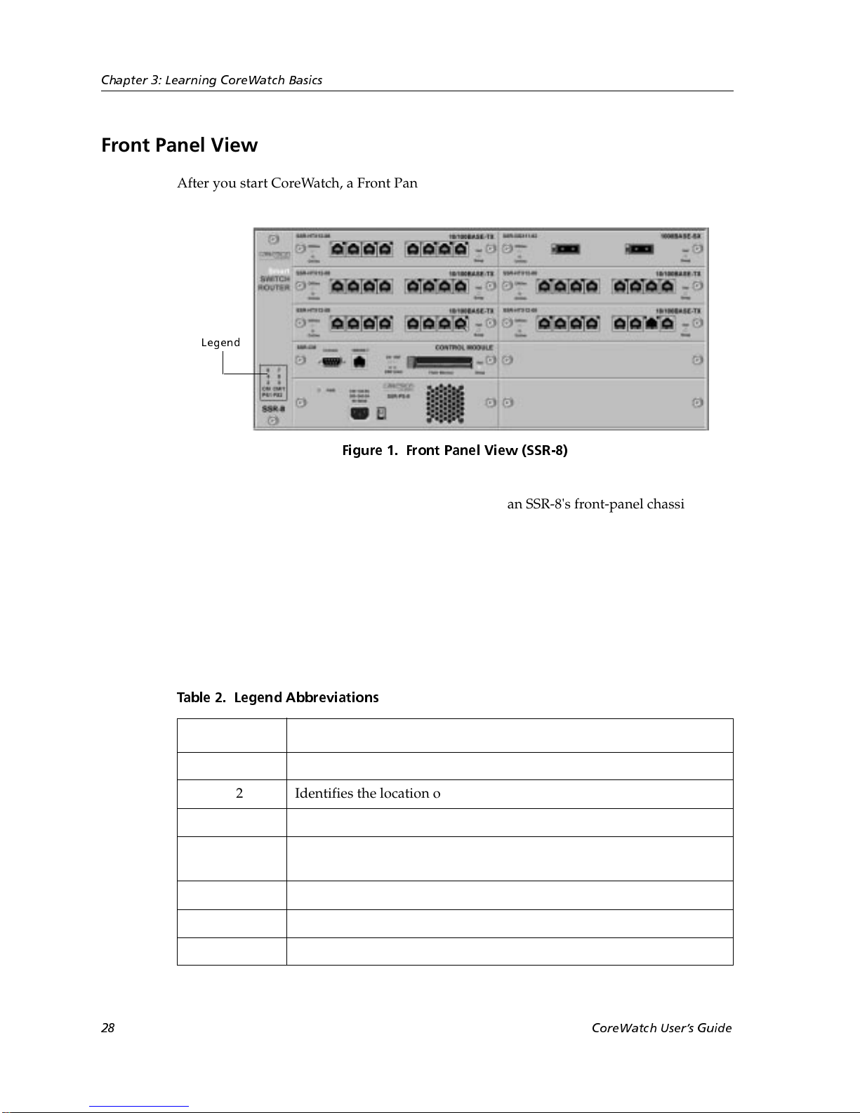
After you start CoreWatch, a Front Panel view similar to the following appears:
Legend
Figure 1. Front Pane l Vie w (SSR-8)
The Front Panel view is a graphical representation of an SSR-8's front-panel chassis. You
can use this view to do the following:
• Obtain port statistics
• Configure ports
• Check the status of ports
The legend identified in the previous figure includes the abbreviations described in the
following table:
Table 2. Legend Abbreviations
Abbreviation Description
PS1 Identifies the location of the SSR's main power supply.
PS2 Identifies the location of the SSR's redundant power supply.
CM Identifies the location of the SSR's Control Module.
CM/1 Indicates the location of slot 1 of the SSR chassis. Slot 1 can accept
either the SSR's Control Module or any module the SSR supports.
2 Indicates the location of slot 2 of the SSR chassis.
3 Indicates the location of slot 3 of the SSR chassis.
4 Indicates the location of slot 4 of the SSR chassis.
28 CoreWatch Users Guide
Page 29
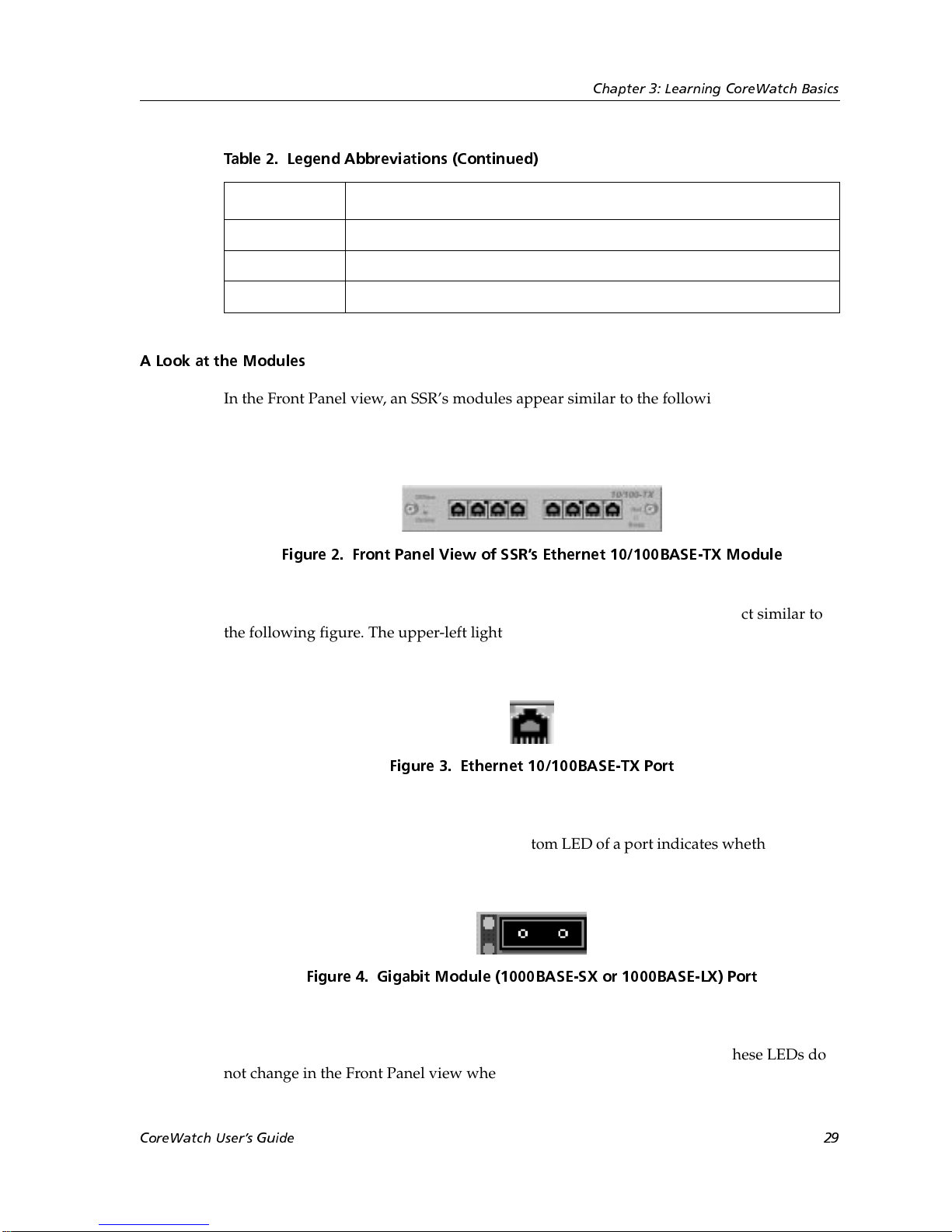
Table 2. Legend Abbreviations (Continued)
Abbreviation Description
5 Indicates the location of slot 5 of the SSR chassis.
6 Indicates the location of slot 6 of the SSR chassis.
7 Indicates the location of slot 7 of the SSR chassis.
A Look at the Modules
In the Front Panel view, an SSR’s modules appear similar to the following figure. This
figure is for an Ethernet 10/100BASE-TX module, but the information CoreWatch displays
to represent a module depends on that module’s type.
Chapter 3: Learning CoreWatch Basics
Figure 2. Front Panel View of SSRs Ethernet 10/100BASE-TX Module
Each port on an Ethernet 10/100BASE-TX module is represented by an object similar to
the following figure. The upper-left light-emitting diode (LED) and the center LED of a
port indicates whether the port is online.
Figure 3. Ethernet 10/100BASE-TX Port
Each port on a Gigabit module (1000BASE-SX or 1000BASE-LX) is represented by an
object similar to the following figure. The bottom LED of a port indicates whether the port
is online.
Figure 4. Gigabit Module (1000BASE-SX or 1000BASE-LX) Port
The Front Panel view also includes online and offline LEDs similar to those on the
physical chassis. Unlike their physical counterparts on the actual chassis, these LEDs do
not change in the Front Panel view whenever a module goes online or offline.
CoreWatch Users Guide 29
Page 30
Chapter 3: Learning CoreWatch Basics
Schematic View
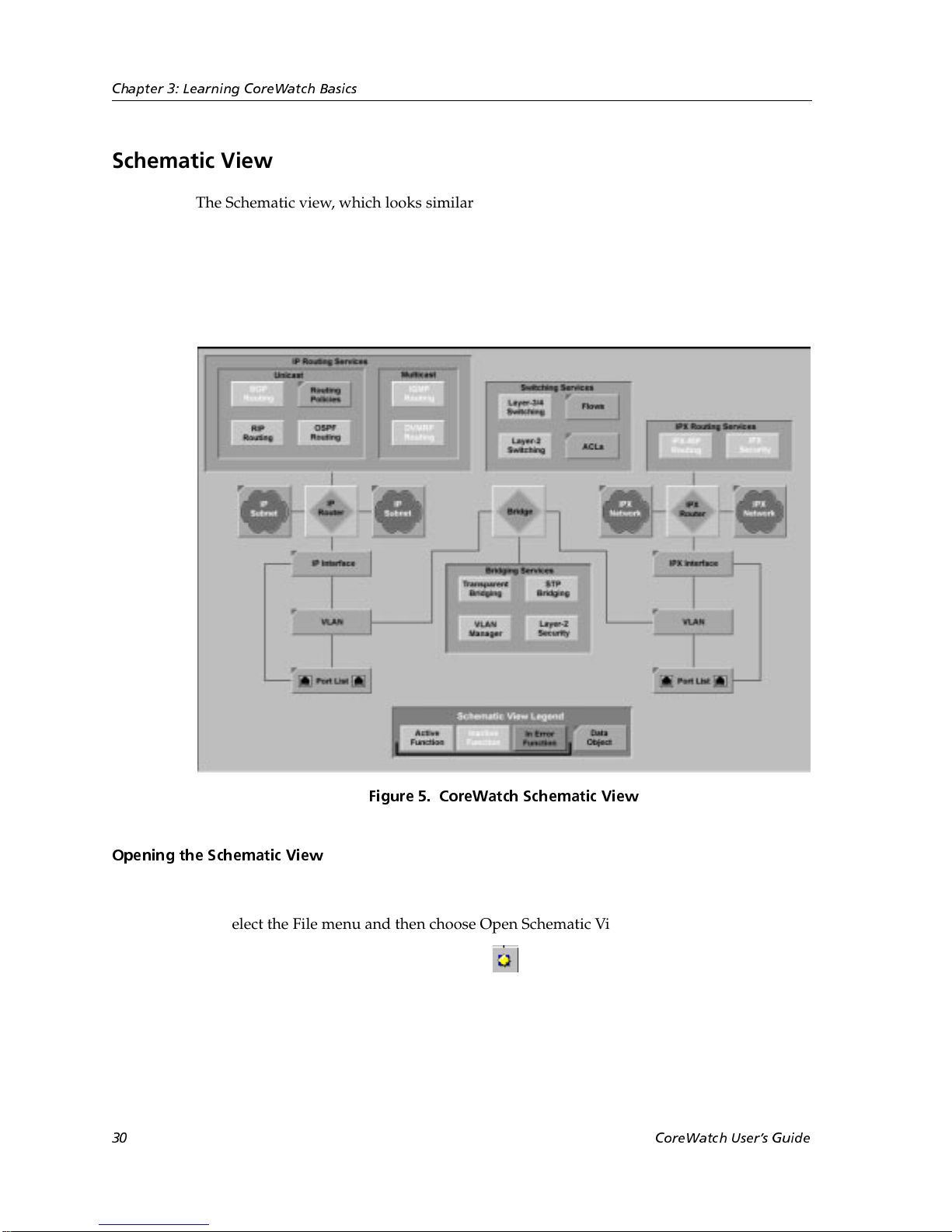
The Schematic view, which looks similar to the following figure, is a graphical
representation of an SSR's functions (such as bridging, switching, and routing services)
and data objects (such as QoS flows). It also indicates which functions are active, inactive,
or in error. The information in the Schematic view is updated every 30 seconds. The
legend that appears at the bottom of the Schematic view indicates the scheme used to
represent the various items displayed in that view.
Opening the Schematic View
To open the Schematic view, do one of the following:
• Select the File menu and then choose Open Schematic View.
• Click the Open Schematic View button on the CoreWatch Toolbar.
30 CoreWatch Users Guide
Figure 5. CoreWatch Schematic View
Page 31
Using the Schematic View
You can use the Schematic view to display the CoreWatch tables and dials discussed later
in this manual, and configure QoS flows and security filters. To do so, perform one of the
following operations:
• Move the cursor to an object, click the right-mouse button, and choose a command
from the menu that appears.
• Double-click a function or data object. CoreWatch then performs the default task for
that function or data object.
CoreWatch Menus
The CoreWatch menus are located at the top of the CoreWatch main window. Use the
commands available on these menus to perform tasks in CoreWatch. For a description of
each menu command, see the “CoreWatch Menus” appendix of this guide.
CoreWatch Toolbar
Chapter 3: Learning CoreWatch Basics
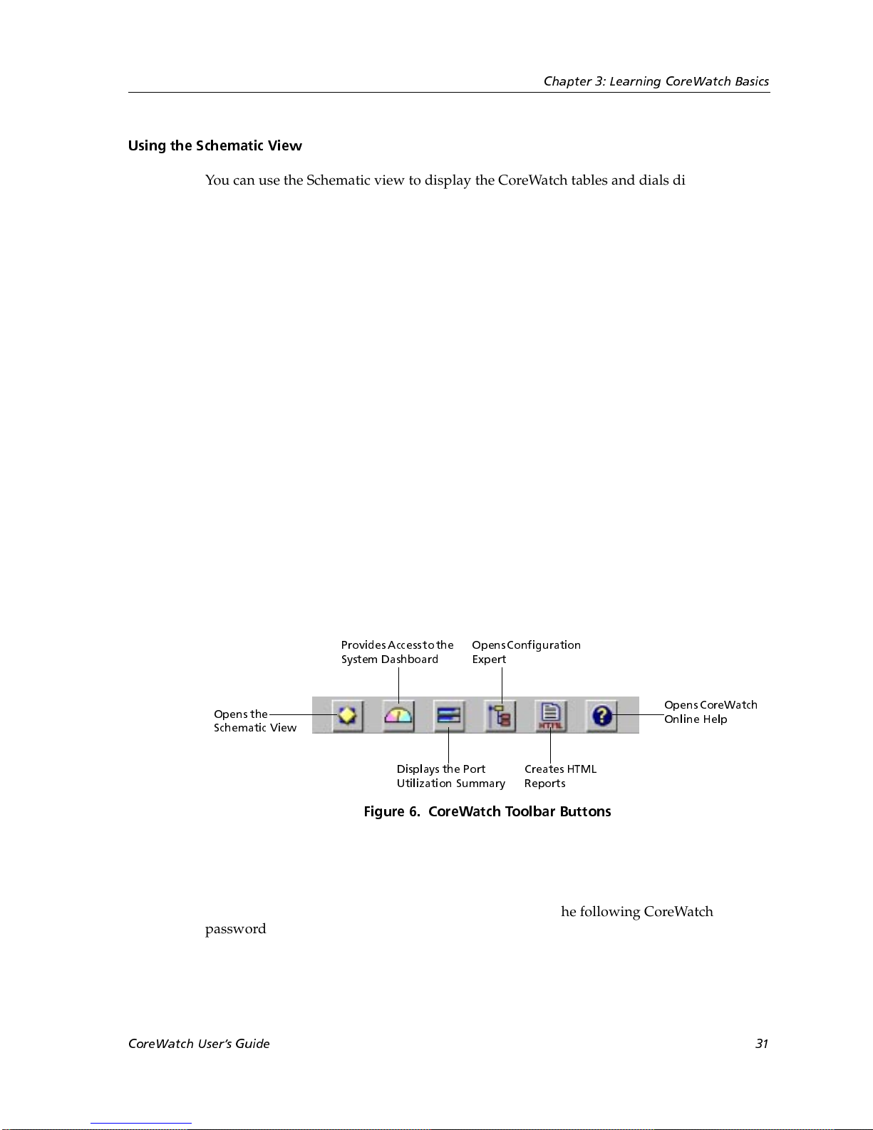
The CoreWatch toolbar is a set of buttons located at the top of the CoreWatch window.
Clicking buttons in this toolbar performs some CoreWatch tasks quickly. The following
figure identifies the function of each CoreWatch toolbar button. Details on the Schematic
View, System Dashboard, Configuration Expert, Port Utilization Summary, reports, and
online help are discussed later in this guide.
Provides Access to the
System Dashboard
Opens the
Schematic View
Figure 6. CoreWatch Toolbar Buttons
CoreWatch Passwords
If you can access Configuration Expert, you can change the following CoreWatch
passwords:
OpensConfiguration
Expert
Displays the Port
Utilization Summary
Opens CoreWatch
Online Help
Creates HTML
Reports
• Login Password, which is the password you are prompted for when you start
CoreWatch.
CoreWatch Users Guide 31
Page 32

Chapter 3: Learning CoreWatch Basics
• Privileged Password, which is the password you are prompted for when you start
Configuration Expert. This password logs you in to Configuration Expert so that you
can then use that utility to configure your SSR.
Changing the Login Password
If you can access Configuration Expert, you can change your CoreWatch Login password.
To change your Login password:
1. Select the Configure menu and choose Change Login Password.
2. If you are prompted for the Privileged password, enter it to start Configuration
Expert. Otherwise, skip to step 3.
You are prompted for the Privileged password if you are not running CoreWatch in
Configure mode.
3. After the Change Login Password form appears, enter your current Login password
in the Old Password text box.
4. Enter your new password in the New Password and Re-enter New Password text
boxes.
5. Click OK.
Changing the Privileged Password
If you can access Configuration Expert, you can change the Privileged password. To
change the Privileged password:
1. Select the Configure menu and choose Change Privileged Password.
2. If you are prompted for the Privileged password, enter it to start Configuration
Expert. Otherwise, skip to step 3.
You are prompted for the Privileged password if you are not running CoreWatch in
the configure mode.
3. After the Change Privileged Password form appears, enter your current Privileged
password in the Old Password text box.
4. Enter your new password in the New Password and Re-enter New Password text
boxes.
5. Click OK.
32 CoreWatch Users Guide
Page 33
Accessing Help
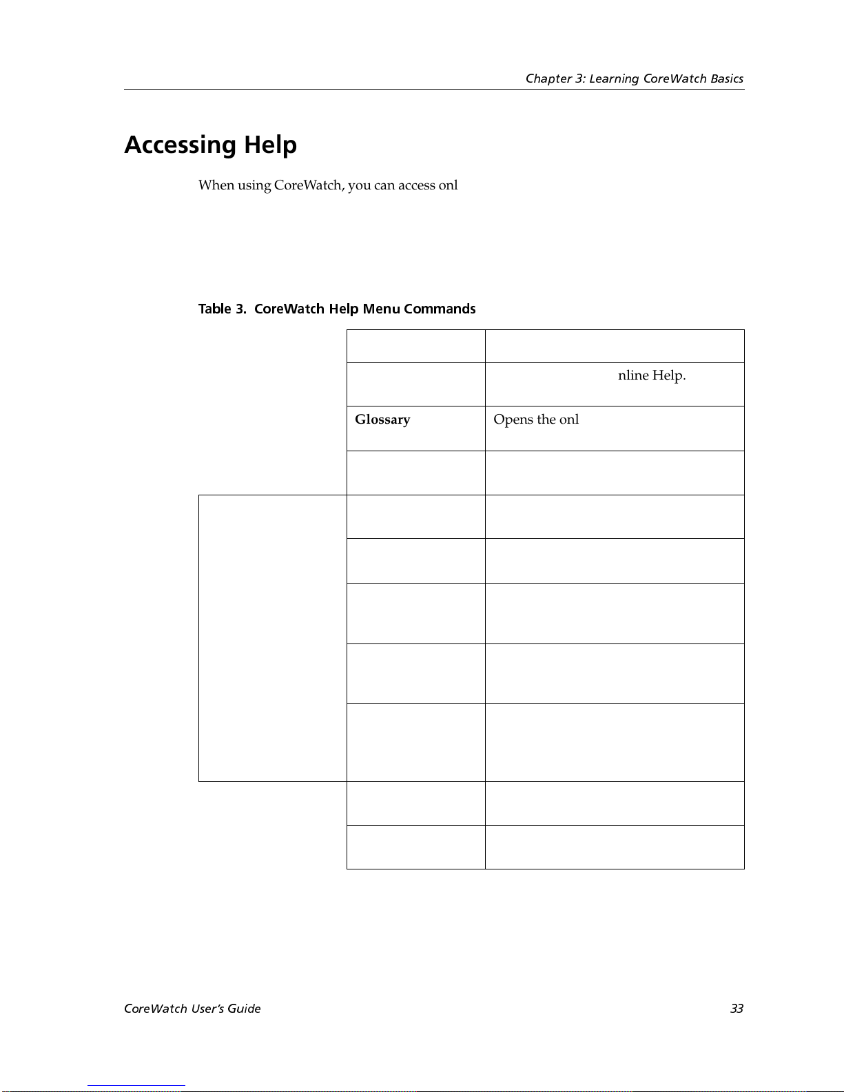
When using CoreWatch, you can access online help by choosing commands from the Help
menu or clicking the Help button. If you click the Help button, CoreWatch displays help
specific to the form, dialog box, or other item you are currently using. The following table
describes the commands you can choose from the Help menu. As the table indicates, you
can choose some commands directly from the Help menu and other commands from the
Cabletron Web Site submenu.
Table 3. CoreWatch Help Menu Commands
Chapter 3: Learning CoreWatch Basics
Command Description
Cabletron Web Site
submenu
Contents and
Index
Glossary Opens the online help glossary for
Release Note Displays the release note(s) for your
Product News Displays information about Cabletron
White Papers Provides access to technical discussions
Frequently Asked
Questions
Technical Support Displays information about how to
Send Feedback Displays a form that you may use to let
Opens CoreWatch Online Help.
CoreWatch.
version of CoreWatch.
Systems products.
of Cabletron Systems products.
Provides technical support for some
issues or concerns that you may have
while using CoreWatch.
contact Cabletron Systems technical
support.
Cabletron Systems know what you
think about its products. You can
complete and send this form online.
CoreWatch Users Guide 33
Cabletron Home
Page
About CoreWatch Displays information about which
Displays the Cabletron Systems home
page in your Web browser.
version of CoreWatch you are using.
Page 34

Chapter 3: Learning CoreWatch Basics
Exiting CoreWatch
To exit CoreWatch, select the File menu and choose Exit. CoreWatch prompts you to verify
that you want to exit. Click the Quit button.
34 CoreWatch Users Guide
Page 35

Chapter 4
Learning
Configuration
Expert Basics
Configuration Expert is a Cabletron Systems utility that lets you configure an SSR. This
chapter
• provides an overview of Configuration Expert.
• explains how to start Configuration Expert.
• discusses the Configuration Expert window.
• describes the different configuration files Configuration Expert uses.
• explains the purpose of Configuration Expert’s wizards and dialog boxes.
• discusses copying and deleting objects.
• explains how to save your changes.
• discusses exiting Configuration Expert.
If you prefer to configure your SSR using commands instead of Configuration Expert, see
the SSR Command Line Interface Reference Manual.
What Is Configuration Expert?
You can use Configuration Expert to perform the following tasks:
• Change system information
• Configure bridging polices
CoreWatch Users Manual 35
Page 36

Chapter 4: Learning Configuration Expert Basics
• Configure VLANs
• Configure IP and IPX routing
• Configure multicast routing
• Set QoS policies
• Set ACLs and security filters
• Configure multiple configuration files on the SSR
Like CoreWatch, Configuration Expert is a Java-based GUI. This GUI offers drag-anddrop setup and administration for VLANs and ACLs. It also supports comprehensive
configuration through wizards, dialog boxes, and drag-and-drop operations.
Starting Configuration Expert
You can start Configuration Expert from either the Front Panel view or the Schematic
view. Separate discussions on starting Configuration Expert from the different views
follow.
Opening Configuration Expert from the Front Panel View
To open Configuration Expert from the Front Panel view:
1. If you are not currently in the Front Panel view, switch to it by clicking the CoreWatch
main window.
2. Do one of the following:
– Select the Configure menu and choose Open Configuration Expert.
– Click the Configuration Expert button on the CoreWatch toolbar.
3. If the Configuration Expert login form appears, enter the Privileged password and
click OK.
The Configuration Expert window appears. For details on this window, see “A Look at the
Configuration Expert Window” on page 38.
36 CoreWatch Users Manual
Page 37
Chapter 4: Learning Configuration Expert Basics
Opening Configuration Expert from the Schematic View
To open Configuration Expert from the Schematic view:
1. If you are not currently in the Schematic view, switch to it by doing one of the
following:
– Select the File menu and then choose Open Schematic View.
– Click the Open Schematic View button on the CoreWatch toolbar.
2. Right click an object in the Schematic view and then choose the appropriate
configuration command from the pop-up menu that appears.
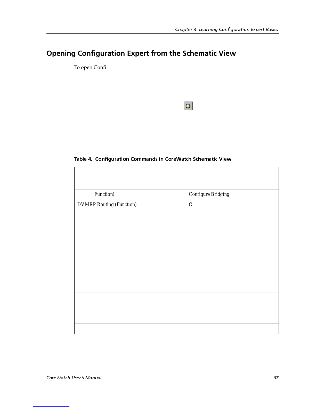
The following table indicates which configuration command to choose for the
Schematic view functions and data objects from which you can open Configuration
Expert.
Table 4. Configuration Commands in CoreWatch Schematic View
Schematic View Command
ACLs (Data Object) Configure Security
Bridge (Function) Configure Bridging
DVMRP Routing (Function) Configure DVMRP
Flows (Data Object) Configure QOS
IGMP Routing (Function) Configure IGMP
IP Interface (Data Object) Configure IP Interfaces
IP Router (Function) Configure Routing
IPX Router (Function) Configure Routing
IPX-RIP Routing (Function) Configure RIP
IPX Security (Function) Configure IPX Security
Layer-2 Switching (Function) Configure QoS Profiles
Layer-3/4 Switching (Function) Configure QoS Profiles
Layer-2 Security (Function) Configure L2 Security
Port List (Data Object for IP or IPX) Configure Chassis
RIP Routing (Function ) Configure RIP
CoreWatch Users Manual 37
Page 38
Chapter 4: Learning Configuration Expert Basics
Table 4. Configuration Commands in CoreWatch Schematic View (Continued)
Schematic View Command
STP Bridging (Function) Configure STP
Transp arent Bridging (Function) Configure Bridging
VLAN (Data Object for IP or IPX) Configure VLAN
3. If the Configuration Expert login form appears, enter the Privileged password and
click OK.
The Configuration Expert window appears. For details on this window, see “A Look at the
Configuration Expert Window” next.
A Look at the Configuration Expert Window
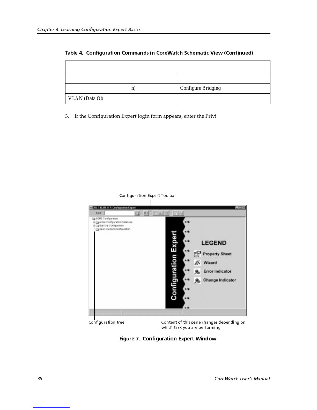
When you start Configuration Expert, a window similar to the following appears:
Configuration Expert Toolbar
Configuration tree Content of this pane changes depending on
which task you are performing
Figure 7. Configuration Expert Window
38 CoreWatch Users Manual
Page 39
The left pane of the Configuration Expert window includes the configuration tree, which
you use to navigate to the objects (modules, ports, system, bridging, routing, and so on)
you want to create, edit, or delete while configuring the SSR. For details on the
configuration tree, see “Configuration Tree” next.
The contents of the right pane changes depending on what task you are performing in
Configuration Expert. Initially the right pane contains the legend that describes some of
the Configuration Expert icons. As you configure the SSR, the right pane will contain the
wizard or dialog box necessary for the configuration task you are performing.
The Configuration Expert Toolbar at the top of the window is used to perform some
Configuration Expert tasks as discussed in “A Look at the Configuration Tree Icons” on
page 42.
Configuration Tree
The configuration tree is a graphical representation of the SSR’s configuration. The
configuration tree includes the configuration files discussed in “Configuration Files” on
page 41. When you are configuring the SSR, you can use the configuration tree to view the
contents of the configuration files so you can add, edit, or delete objects in those files.
Chapter 4: Learning Configuration Expert Basics
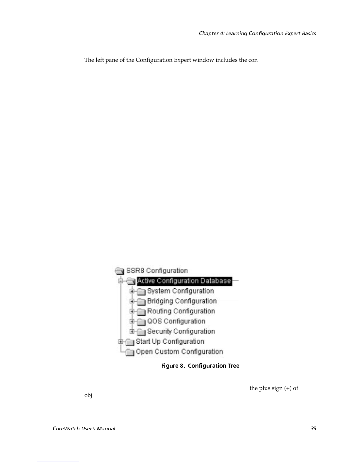
You can view the contents of a configuration file by double-clicking its name or icon in the
configuration tree. When you do so, Configuration Expert displays the file’s subtree. As
shown in the following figure, a configuration file’s subtree includes system, bridging,
routing, QoS, and security configuration objects. There are separate subtrees for each
configuration file.
Double-clicking a
configuration file
displays that file’s
subtree
Figure 8. Configuration Tree
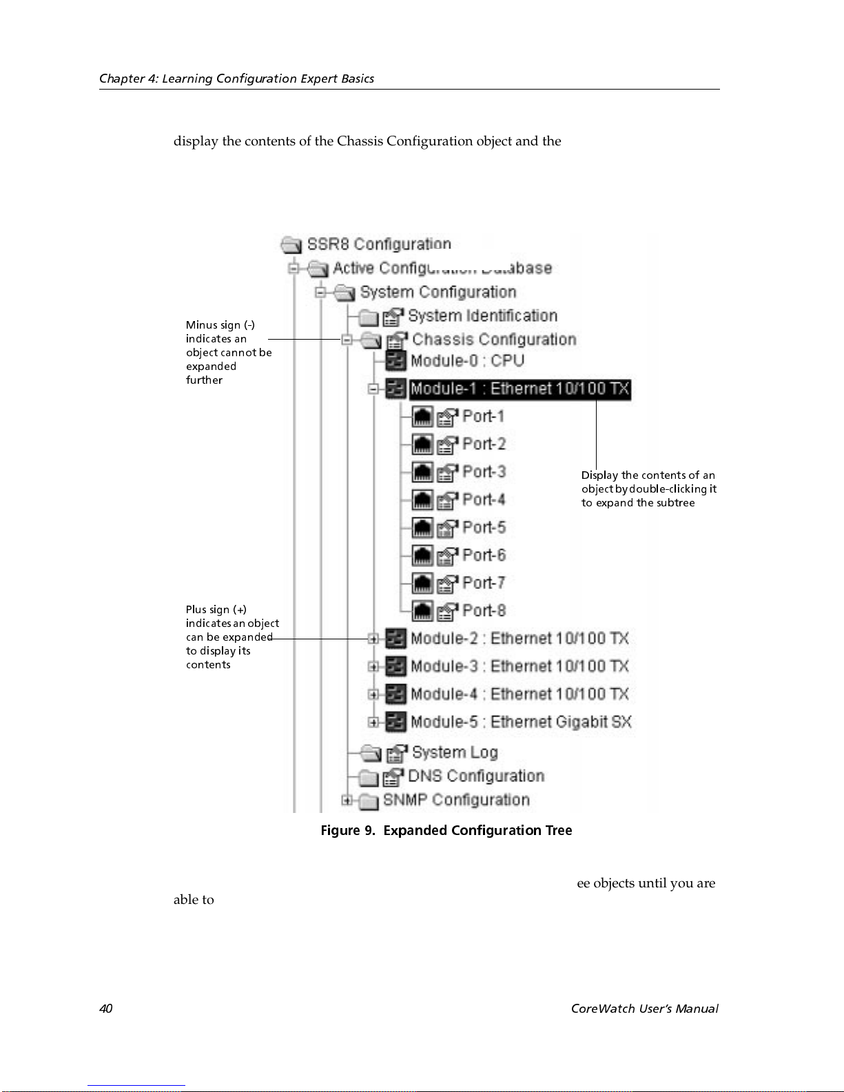
You navigate a subtree by double-clicking its objects or clicking the plus sign (+) of
objects. As you do so, Configuration Expert expands the subtree to display the object’s
contents. In the following figure, the System Configuration subtree has been expanded to
CoreWatch Users Manual 39
Page 40
Chapter 4: Learning Configuration Expert Basics
display the contents of the Chassis Configuration object and the Module-1 object. As the
figure shows, a plus sign (+) indicates an object can be expanded further and a minus sign
(-) indicates an object cannot be expanded. You can close an expanded object by doubleclicking it or clicking its minus sign (-).
Minus sign (-)
indicates an
object cannot be
expanded
further
Display the contents of an
objectby double-clicking it
to expand the subtree
Plus sign (+)
indicates an object
can be expanded
to display its
contents
Figure 9. Expanded Configuration Tree
While configuring the SSR, you can continue double-clicking subtree objects until you are
able to select the object you want to add, edit, or delete. After you select a configurable
object, the wizard or dialog box used to configure that object appears in the right pane of
the Configuration Expert window.
40 CoreWatch Users Manual
Page 41
Configuration Files
O
Configuration Expert stores SSR configuration information in the following configuration
files:
• Active Configuration—a file containing the configuration settings for the current SSR
session.
• Startup Configuration—a file containing the configuration settings used whenever the
SSR is started.
• Custom Configuration—a file in which you can save the settings of an Active
Configuration file. Custom Configuration files let you:
– Save changes when you have not finished making changes to an Active
– Quickly change the SSR’s configuration for different environments. Suppose you
Chapter 4: Learning Configuration Expert Basics
Configuration file or you are not ready to have such changes take effect at this time
or later when you restart the SSR.
are configuring the SSR to establish traffic priority for an accounting department.
You could create one Custom Configuration file for the handling of traffic at the
end-of-a-month, and create another Custom Configuration file for handling traffic
at the end of the fiscal year. You would then be able to quickly switch traffic
priority by configuring the SSR with the desired Custom Configuration file.
You can save configuration settings by committing those changes to a configuration file as
discussed in “Committing Your Configuration Changes” on page 46.
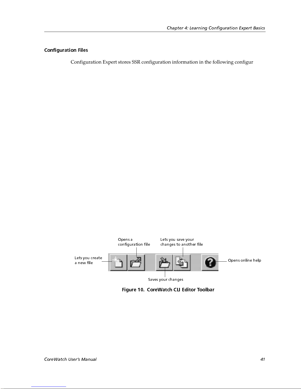
Configuration Expert includes a CLI editor that you can open by selecting the Configure
menu and choosing Open Config CLI Editor. Use this editor to type CLI commands into
a configuration file. The following figure summarizes the CLI Editor toolbar, which is
located at the top of the CLI Editor window:
pens a
configuration file
Lets you create
a new file
Lets you save your
changes to another file
Opens online help
Saves your changes
Figure 10. CoreWatch CLI Editor Toolbar
CoreWatch Users Manual 41
Page 42
Chapter 4: Learning Configuration Expert Basics
A Look at the Configuration Tree Icons
The configuration tree uses the icons described in the following table to represent
configuration tree objects, to indicate that there is a wizard or dialog box associated with
an object, and to identify configuration file changes and errors:
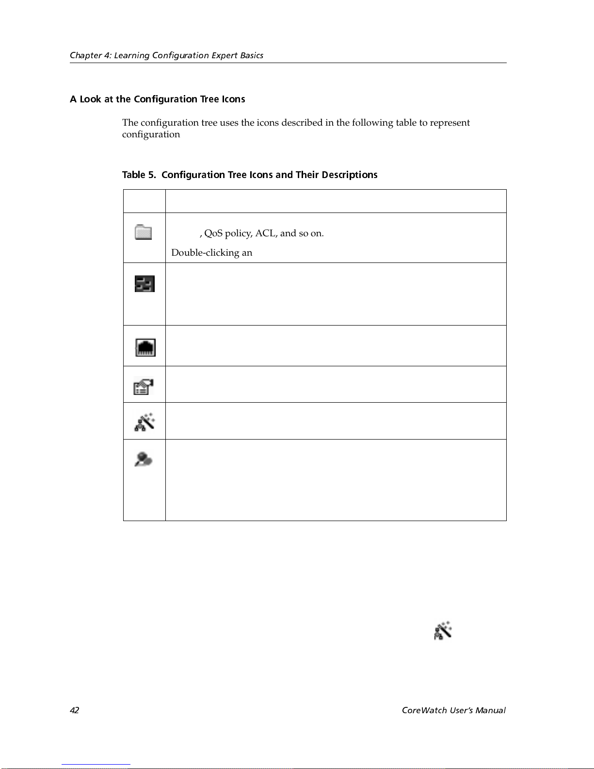
Table 5. Configuration Tree Icons and Their Descriptions
Icon Description
Represents a configuration file or configurable object, such as an interface,
VLAN, QoS policy, ACL, and so on.
Double-clicking an object’s folder icon displays the contents of that object.
Represents a chassis module.
Double-clicking a module icon displays that module’s ports. However, this is
not the case with the Control Module icon because there are no ports
associated with the Control Module.
Represents a port.
Indicates that a dialog box is associated with an object. You can configure the
object by using its dialog box.
Indicates that a wizard is associated with an object. You can configure the
object by using its wizard.
Identifies either configuration file changes or errors.
• Blue indicators identify new or modified objects.
• Red indicators identify those objects that are not configured properly.
These indicators appear only after you commit your changes to the Active
configuration file.
Wizards and Dialog Boxes
You can configure objects through wizards and dialog boxes, which are forms that prompt
you for the appropriate configuration information.
Wizards take you step-by-step through the process of adding objects that are complex to
configure. If you add an object using a wizard, there will be a wizard icon next to that
object.
42 CoreWatch Users Manual
Page 43
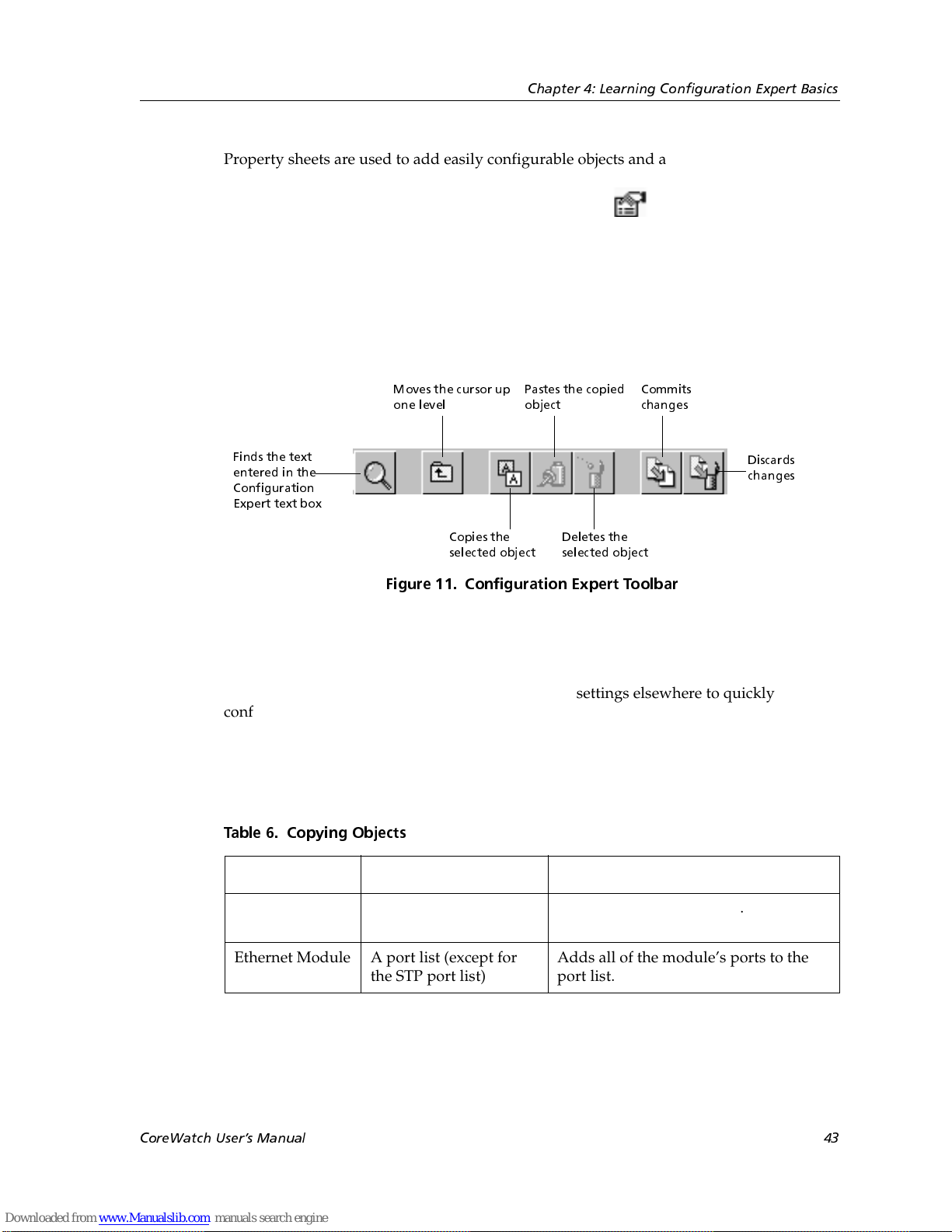
Property sheets are used to add easily configurable objects and also to modify the
configuration settings of objects once they have been added. If there is a dialog box
associated with an object, there will be a dialog box icon next to that object.
Configuration Expert Toolbar
The Configuration Expert toolbar is a set of buttons located at the top of the Configuration
Expert window. The following figure identifies the function of each Configuration Expert
Toolbar button:
Chapter 4: Learning Configuration Expert Basics
Finds the text
entered in the
Configuration
Expert text box
Copying Objects
You can copy objects and apply their configuration settings elsewhere to quickly
configure ports, ACLs, and QoS profiles as well as easily setup and administer VLANs.
The following table lists the objects from which you can copy configuration settings,
indicates the objects to which those settings can be applied, and describes the effect of
copying those objects. These objects must be located in the same configuration file.
Table 6. Copying Objects
Moves the cursor up
one level
Copies the
selected object
Pastes the copied
object
Deletes the
selected object
Commits
changes
Figure 11. Configuration Expert Toolbar
Discards
changes
Object Apply To Effect
Port Another port list (except
Ethernet Module A port list (except for
CoreWatch Users Manual 43
for the STP port list)
the STP port list)
Adds a port to the port list.
Adds all of the module’s ports to the
port list.
Page 44

Chapter 4: Learning Configuration Expert Basics
Table 6. Copying Objects (Continued)
Object Apply To Effect
ACL Interface Applies the security settings of an IP
VLAN Interface Adds a VLAN to an IP or IPX interface.
Interface QoS profile Adds an IP or IPX interface to the QoS
You can copy an object’s configuration settings by copying and pasting that object or by
dragging it to another object. Separate discussions on each method follow.
As the previous table states, you can copy a port or module to a port list (such as those
belonging to VLANs and static ARP entries). For an example of copying a port or module
from one port list to another, see “Dragging Ports to Add Them to a VLAN” on page 97.
ACL to an IP interface or an IPX, IPX
RIP, or IPX SAP ACL to an IPX
interface.
profile’s list of interfaces. The settings
of the QoS profile will then apply to the
interface.
Copying and Pasting an Object
To copy an object’s configuration settings by copying and pasting an object:
1. Select the object that you want to copy.
For details on which objects you can copy, see “Copying Objects” on page 43.
2. Click the Copy button in the Configuration Expert toolbar.
3. If necessary, double-click objects in the configuration tree until you locate the object to
which you want to apply the configuration settings of the copied object.
For details on the objects to which you can apply configuration settings, see “Copying
Objects” on page 43.
4. Select the object to which you want to apply the configuration settings.
5. Click the Paste button in the Configuration Expert toolbar.
Dragging Objects to Copy Their Configuration Settings
You can drag objects to copy their configuration settings. When using this method to copy
ACLs or QoS profiles, you should remember that you drag ACLs to interfaces, but you
drag interfaces to QoS profiles.
44 CoreWatch Users Manual
Page 45

Chapter 4: Learning Configuration Expert Basics
Note:
To drag objects to copy their configuration settings:
1. Double-click objects in the configuration tree until you locate the object from which
2. Double-click objects in the configuration tree until you locate the object to which you
3. Select the object you want to copy. Then drag that object to the object to which you
4. Release the mouse button to apply the configuration settings to the desired object.
Dragging an object from one location to another copies the object’s configuration
settings. It does not move the object.
you want to copy configuration settings.
For details on which objects you can copy, see “Copying Objects” on page 43.
want to apply the configuration settings.
For details on the objects to which you can apply configuration settings, see “Copying
Objects” on page 43.
want to apply the configuration settings.
Configuration Expert displays a folder icon while you are dragging an object. A green
check mark appears whenever the cursor is on an object to which the configuration
settings can be applied.
Finding Objects
You can search for an object in the configuration tree by entering all or part of the name of
an object you want to find. To do so, enter the name of the object you want to find in the
text box located next to the Configuration Expert toolbar and then click the Find button
in the Configuration Expert toolbar.
Deleting Objects
You can delete any object you add except for VLANs. To delete an object:
1. Select the object you want to delete and then click the Delete button in the
Configuration Expert toolbar.
2. Click OK when Configuration Expert prompts you to verify whether you want to
delete the object.
Order of Configuration Tasks
Perform configuration tasks in the following order:
1. Provide system information (such as the SSR’s name and location), define the SSR’s
ports, set up the SSR for a SYSLOG server and Domain Naming System (DNS)
CoreWatch Users Manual 45
Page 46

Chapter 4: Learning Configuration Expert Basics
servers, and configure the SSR for SNMP traps. For details on performing these tasks,
see Chapter 5: “Changing System Settings” on page 49.
2. Configure bridging on the SSR as discussed in Chapter 6: “Configuring SSR Bridging”
on page 63.
3. Group physical ports on the SSR by configuring VLANs as discussed in Chapter 7:
“Configuring VLANs on the SSR” on page 81.
4. If you are using the SSR in an IP environment, create IP interfaces and then configure
those interfaces for unicast or multicast routing.
For details on IP interfaces, see Chapter 8: “Configuring IP Interfaces for the SSR” on
page 101. For details on unicast routing, see Chapter 9: “Configuring Unicast Routing
on the SSR” on page 119. For details on multicast routing, see Chapter 10: “Configuring
Multicast Routing on the SSR” on page 135.
5. If you are using the SSR in an IPX environment, configure IPX interfaces as discussed
in Chapter 11: “Configuring the SSR for IPX Routes” on page 147.
6. If you want to control traffic on the SSR, configure the SSR’s QoS policies as discussed
in Chapter 12: “Configuring QoS on the SSR” on page 167.
7. If you want to set security on the SSR, define ACLs and Layer-2 security filters as
discussed in Chapter 13: “Configuring Security on the SSR” on page 195.
Committing Your Configuration Changes
When you finish working in a wizard or dialog box, Configuration Expert temporarily
saves the changes you have made. To apply your changes, however, you will need to
commit them to a configuration file. You can commit your changes to the Active
Configuration file, the Startup Configuration file, both of those files, or a Custom
Configuration file.
To commit your configuration changes:
1. Click the Commit button in the Configuration Expert toolbar.
A Commit Configuration form similar to the following appears. The configuration file
in which you made your changes is listed in the From Configuration list box.
46 CoreWatch Users Manual
Page 47
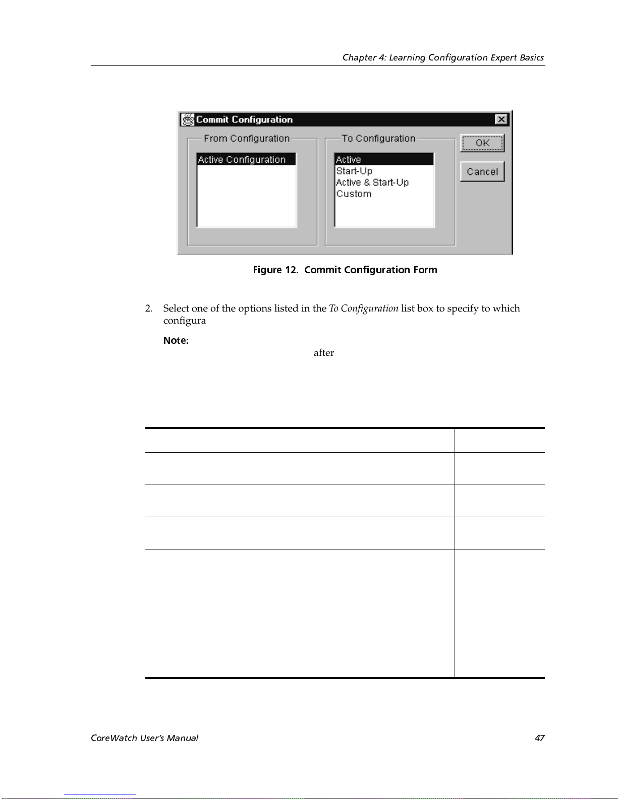
Chapter 4: Learning Configuration Expert Basics
Figure 12. Commit Configuration Form
2. Select one of the options listed in the To Confi gu ration list box to specify to which
configuration file or files you want to apply your changes.
Note:
You should commit changes made in the Active Configuration file to the
Active Configuration file after normal business hours or at another time that
would not disrupt the network. This helps prevent problems in case you have
not properly configured the SSR.
The following table discusses the effect of selecting the different options listed in the
To Configuration list box:
If you want to Select
Apply your changes to the current SSR session. The changes will
Active
not remain in effect if you restart the SSR.
Make your changes effective the next time the SSR is restarted and
Start-Up
for subsequent sessions.
Apply your changes to the current SSR session as well as
Active & Start-Up
subsequent sessions.
Save your changes to a Custom Configuration file. You typically
Custom
select this option for the following reasons:
• You are not finished making changes to an Active
Configuration file.
• You are not ready to have your changes take effect at this time
or whenever the SSR is started.
• You want to create a set of configuration files so that you will be
able to quickly change the environment of the SSR.
3. Click OK.
CoreWatch Users Manual 47
Page 48

Chapter 4: Learning Configuration Expert Basics
If you commit your changes to the Active Configuration file, the SSR checks the file for
configuration errors.
Note:
4. If you selected Custom, you will be prompted to enter the name of the Custom
Configuration file that you want to save your changes. Specify a filename and then
click OK.
Configuration Expert displays a red indicator next to any object that the SSR
determines is not configured properly.
Discarding Your Configuration Settings
If you make changes to a configuration file and then decide you want to discard all of
those changes, click the Discard button in the Configuration Expert Toolbar.
Exiting Configuration Expert
To exit Configuration Expert and return to CoreWatch, click the button in the upper
right of the Configuration Expert window.
If Configuration Expert prompts you to commit your changes because you have not
already done so, click Yes. Then commit your changes as discussed in “Committing Your
Configuration Changes” on page 46.
48 CoreWatch Users Manual
Page 49
Chapter 5
Changing System
Settings
You change system settings through the System Configuration object of a configuration
file. This chapter discusses using Configuration Expert to perform the following tasks:
• Providing system information to set the SSR’s name, identify who users should contact
regarding the SSR, and indicate the SSR’s location.
• Configuring an SSR’s ports.
• Configuring the SSR to send system messages to a SYSLOG server.
• Configuring the SSR for Domain Naming System (DNS) servers.
• Setting up targets for SNMP traps and establishing SNMP community strings for those
traps.
Providing System Information
Before setting up the SSR, you may want to set the SSR’s name, provide information about
who users should contact regarding the SSR, and indicate where the SSR is located. To
enter this system information:
1. Start Configuration Expert if you have not already done so.
2. Open the configuration file you want to modify and then double-click that file’s
System Configuration object.
3. Select the System Identification object.
CoreWatch Users Guide 49
Page 50
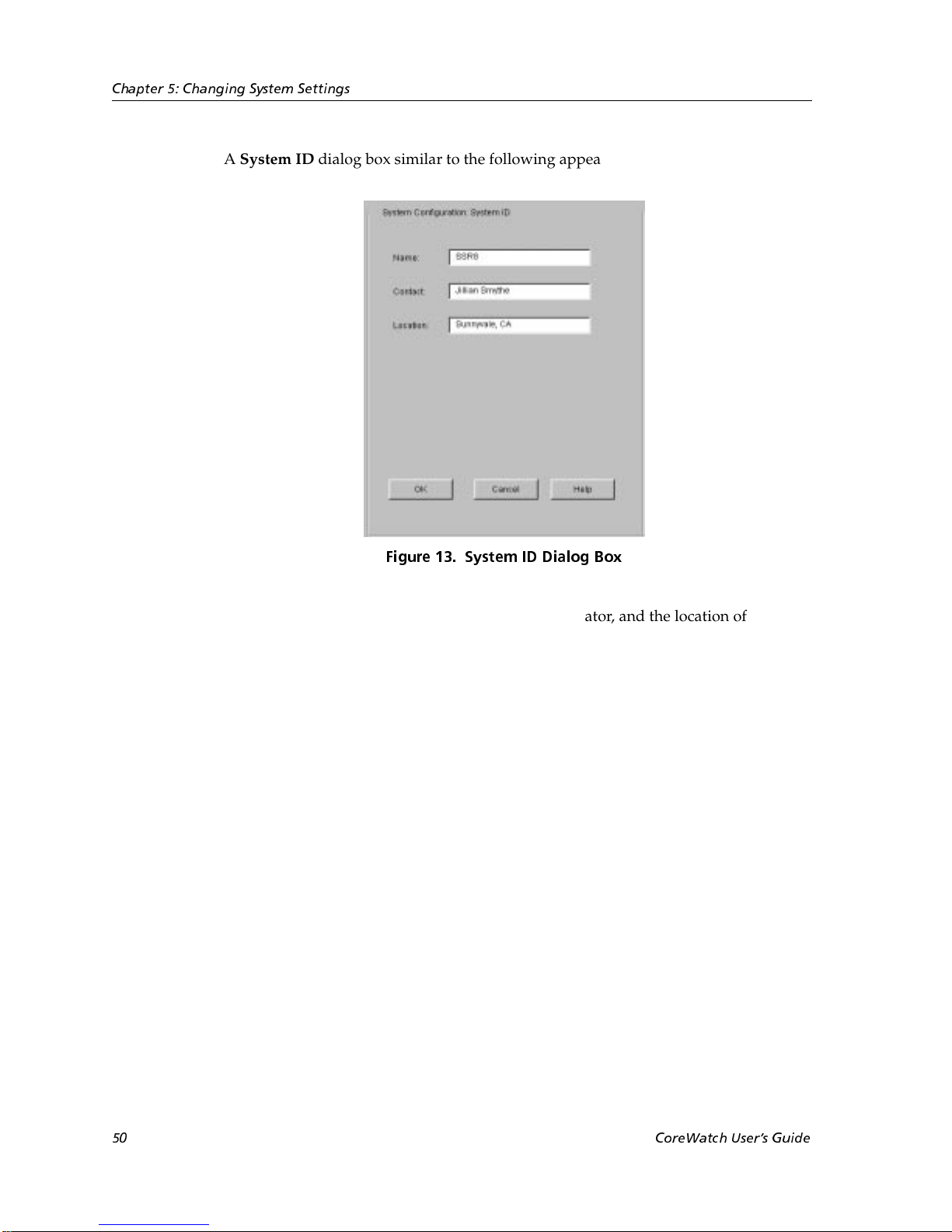
Chapter 5: Changing System Settings
A System ID dialog box similar to the following appears:
4. Enter the SSR’s name, the name of the SSR administrator, and the location of the SSR
in the appropriate text boxes.
5. Click OK.
Configuring Ports
Configuration Expert lets you enable and disable ports as well as configure the following
characteristics:
• Operating mode (half-duplex or full-duplex).
In half-duplex mode, a port can transmit data in only one direction at a time between
two stations.
In full-duplex mode, a port can simultaneously send and receive data.
• Port speed (10-Mbps or 100-Mbps). This parameter applies only to ports on the
10/100 modules.
• Auto negotiation (for Gigabit Ethernet ports)
Figure 13. System ID Dialog Box
• Hash mode, which controls the distribution of flow entries in Layer-2 and Layer-3
lookup tables. (For more information on hash modes, see “Configuring Global Settings
on All Ports” on page 51.)
50 CoreWatch Users Guide
Page 51
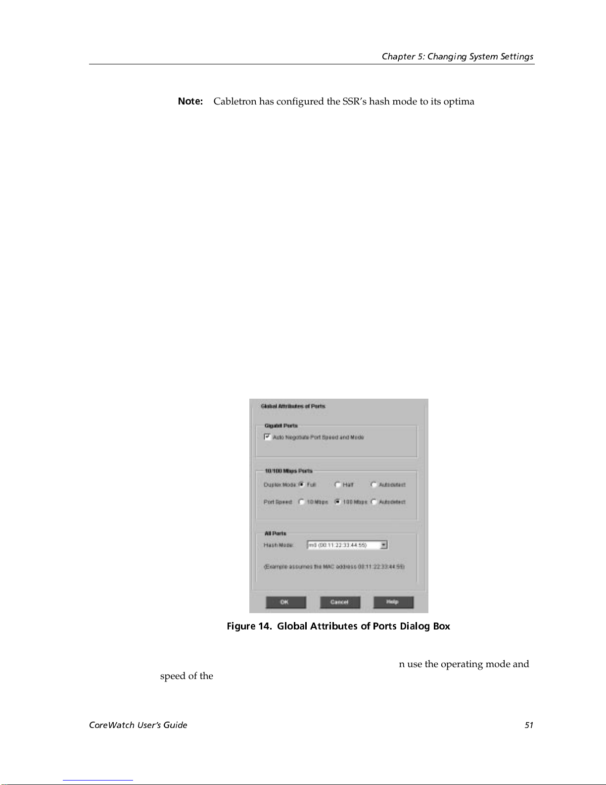
Chapter 5: Changing System Settings
Note:
You can configure global settings for all SSR ports as well as configure individual ports. If
most of an SSR’s ports are to be configured with the same or similar settings, you can first
apply global settings to all ports and then modify those settings on individual ports as
needed. Separate discussions on configuring default settings for all ports and configuring
an individual port follow.
Cabletron has configured the SSR’s hash mode to its optimal setting. It is
recommended you not change the hash mode unless advised to do so by
Cabletron Technical Support.
Configuring Global Settings on All Ports
To configure global settings on all of the SSR’s ports:
1. Start Configuration Expert if you have not already done so.
2. Open the configuration file you want to modify and then double-click that file’s
System Configuration object.
3. Double-click the Chassis Configuration object.
4. Click the Global Port Parameters object.
A Global Attributes of Ports dialog box similar to the following appears:
5. If you want all Gigabit Ethernet ports to detect and then use the operating mode and
speed of the network segment to which those ports are connected, select the Auto
CoreWatch Users Guide 51
Figure 14. Global Attributes of Ports Dialog Box
Page 52

Chapter 5: Changing System Settings
Negotiate Port Speed and Mode check box. Otherwise, clear the check box to disable auto
negotiation on all Gigabit Ethernet ports.
All Gigabit Ethernet ports use auto negotiation. If auto negotiation is not set on a
Gigabit Ethernet port, that port uses the full-duplex mode and operates at 1000 Mbps.
6. If you want to configure 10/100 Mbps Ethernet ports, do one of the following.
Otherwise, skip to step step 7.
– If you want all 10/100 Mbps Ethernet ports to detect and then use the operating
mode or speed of the network segment to which the port is connected, select the
appropriate Autodetect options.
– If you want to set all 10/100 Mbps Ethernet ports’ operating mode or speed to a
specific setting, select the appropriate buttons.
All 10/100 Mbps Ethernet ports use autodetection by default.
The 100 FX ports do not use auto-detection. They always use full-duplex mode and
operate at 100 Mbps.
Note:
7. Set the Layer 2 hash mode for all ports. The hash mode controls the distribution of
flow entries in Layer-2 and Layer-3 lookup tables. Assuming a MAC address of the
value 0011:2233:4455, the following list describes the various hash modes.
– M0 – 0011:2233:4455
– M1 – 0011:2233:5544
– M2 – 0011:3322:4455 (default hash mode)
– M3 – 1100:2233:4455
Note:
8. Click OK.
If you select an operating mode or speed, the setting disables autodetection
for that parameter on the port. For example, if you set the speed of a segment
to 10 Mbps, that segment no longer uses autodetection for the port speed and
will always attempt to operate at 10 Mbps.
Cabletron has configured the SSR’s hash mode to its optimal setting. It is
recommended you not change the hash mode unless advised to do so by
Cabletron Technical Support.
Configuring an Individual Port
Configure an individual port if you want to enable or disable that port or set the port’s
physical characteristics. To configure an individual port:
1. Start Configuration Expert if you have not already done so.
Note:
52 CoreWatch Users Guide
If you open Configuration Expert by clicking a port in the Front Panel view,
Configuration Expert assumes you want to modify that port in the Active
Page 53
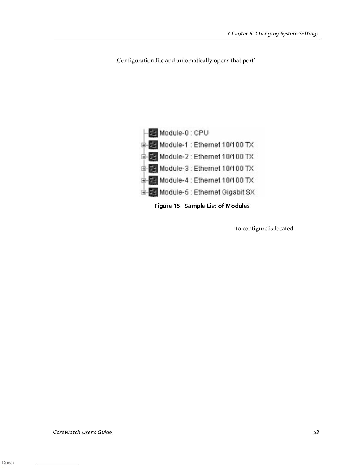
Chapter 5: Changing System Settings
Configuration file and automatically opens that port’s dialog box. If you are
modifying that port in the Active Configuration file, go to step step 6.
2. Open the configuration file you want to modify and then double-click that file’s
System Configuration object.
3. Double-click the Chassis Configuration object.
A list of modules similar to the following appears.
.
Figure 15. Sample List of Modules
4. Double-click the module on which the port you want to configure is located.
CoreWatch Users Guide 53
Page 54
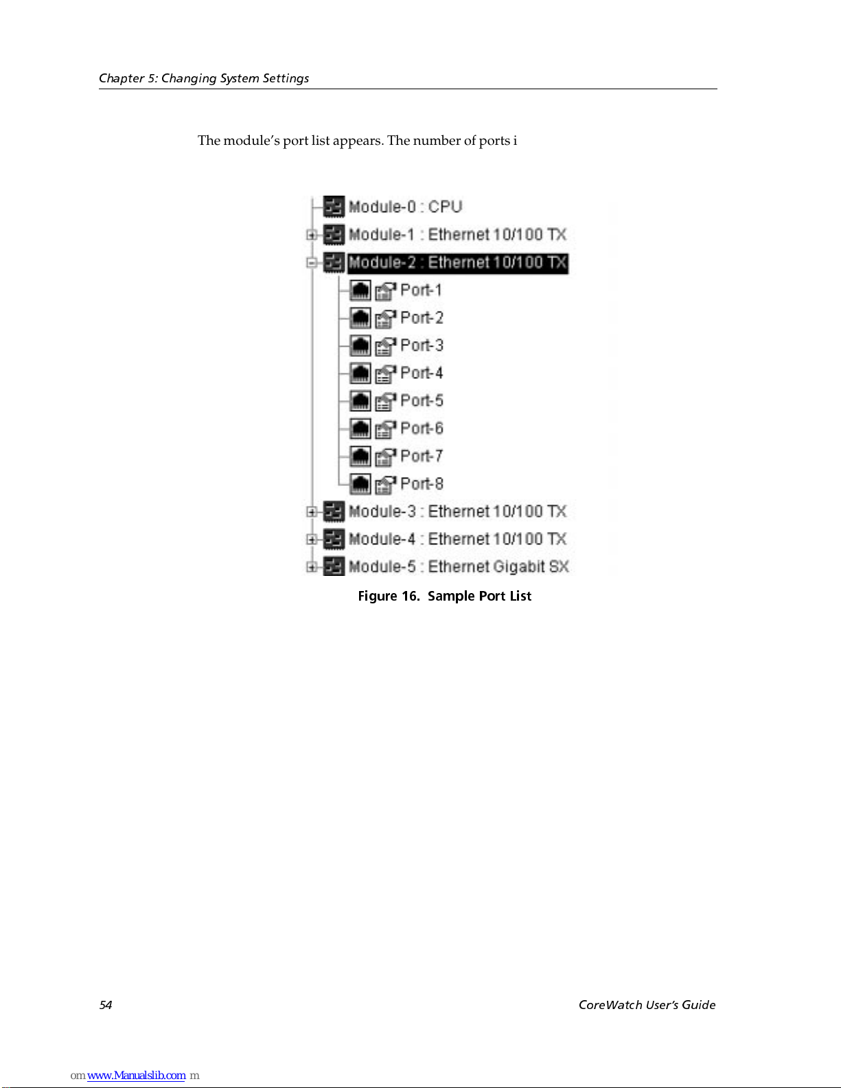
Chapter 5: Changing System Settings
The module’s port list appears. The number of ports in the list depends on the module
type.
Figure 16. Sample Port List
5. Select the port you want to configure.
54 CoreWatch Users Guide
Page 55
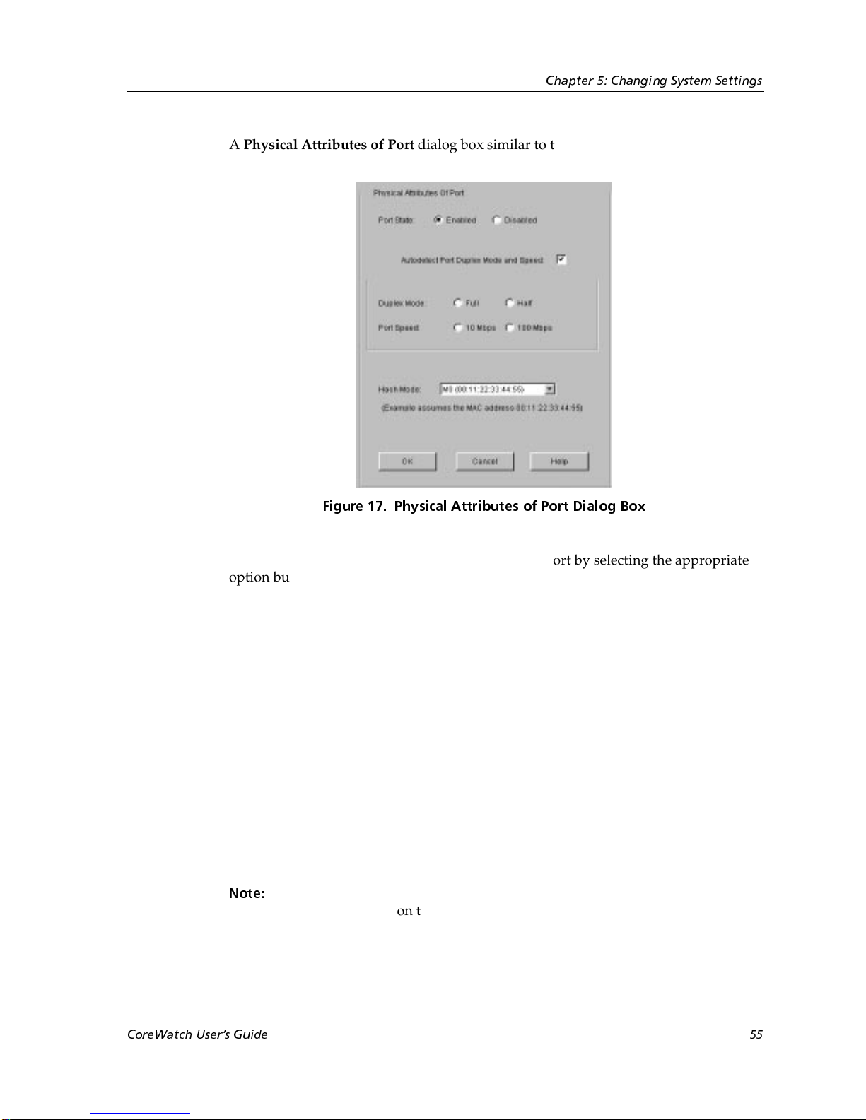
Chapter 5: Changing System Settings
A Physical Attributes of Port dialog box similar to the following appears:
Figure 17. Physical Attributes of Port Dialog Box
6. Specify whether you want to enable or disable the port by selecting the appropriate
option button.
Disabled ports do not send or receive any traffic. You might want to disable unused
ports to prevent network users from inadvertently or unscrupulously connecting to
unoccupied but enabled ports on the SSR.
7. Do one of the following:
– If you want the port to detect and then use the operating mode and speed of the
network segment to which the port is connected, select the Autodetect Port Duplex
Mode and Speed check box. Otherwise, clear the check box to disable autodetection
on the port.
All 10/100 Mbps Ethernet and Gigabit Ethernet ports use autodetection by default.
The 100 FX ports do not use auto-detection. They always use full-duplex mode and
operate at 100 Mbps.
– If you want to set the port’s operating mode or speed to a specific setting, select the
appropriate buttons.
Note:
If you select an operating mode or speed, the setting disables autodetection
for that parameter on the port. For example, if you set the speed of a segment
to 10-Mbps, that segment no longer uses autodetection for the port speed and
will always attempt to operate at 10-Mbps.
CoreWatch Users Guide 55
Page 56

Chapter 5: Changing System Settings
8. Set the Layer 2 hash mode for the port. The hash mode controls the distribution of
flow entries in Layer-2 and Layer-3 lookup tables. Assuming a MAC address of the
value 0011:2233:4455, the following list describes the various hash modes:
– M0 – 0011:2233:4455
– M1 – 0011:2233:5544
– M2 – 0011:3322:4455 (default hash mode)
– M3 – 1100:2233:4455
Note:
9. Click OK.
Cabletron has configured the SSR’s hash mode to its optimal setting. It is
recommended you not change the hash mode unless advised to do so by
Cabletron Technical Support.
Configuring the SSR for a SYSLOG Server
You can configure the SSR to send system messages to a SYSLOG server. To do so, identify
the server the SSR is to send messages to and also specify the type of messages that the
SSR is to send. On the SYSLOG server, you can decide whether to discard the messages,
write them to a file, or send them out to the console.
To configure the SSR for a SYSLOG server:
1. Start Configuration Expert if you have not already done so.
2. Open the configuration file you want to modify and then double-click that file’s
System Configuration object.
3. Select the System Log object.
56 CoreWatch Users Guide
Page 57
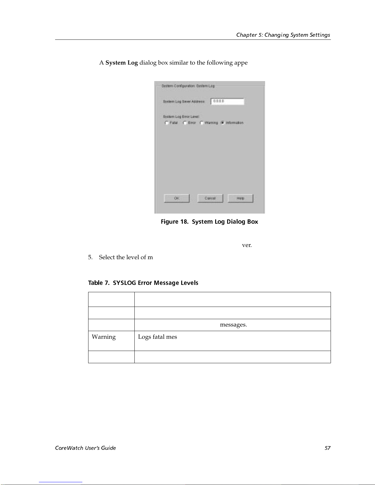
Chapter 5: Changing System Settings
A System Log dialog box similar to the following appears:
Figure 18. System Log Dialog Box
4. Enter the host name or IP address of the SYSLOG server.
5. Select the level of messages you want the SSR to log. You may select one of the levels
described in the following table:
Table 7. SYSLOG Error Message Levels
Level Description
Fatal Logs only fatal messages.
Error Logs fatal messages and error messages.
Warning Logs fatal messages, error messages, and warning messages. This is
the default.
Information Logs all messages, including informational messages.
6. Click OK.
CoreWatch Users Guide 57
Page 58
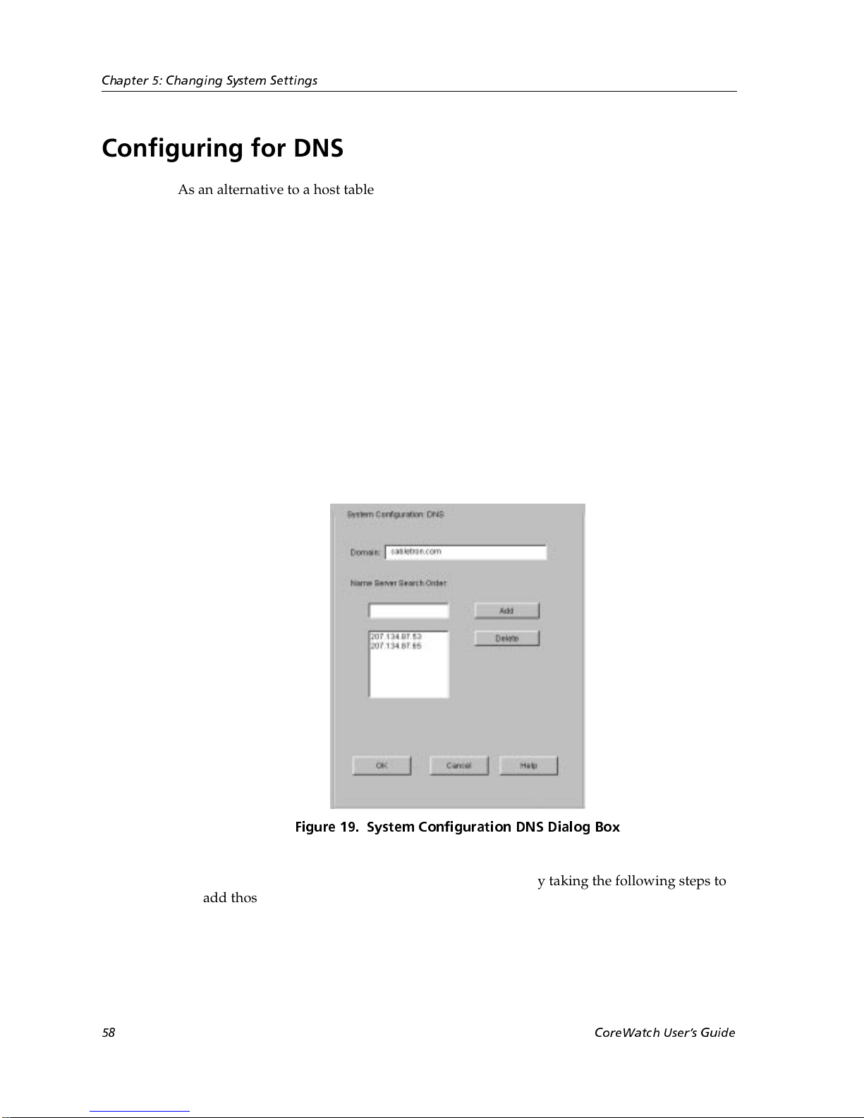
Chapter 5: Changing System Settings
Configuring for DNS
As an alternative to a host table on every system, some networks use a centralized
Domain Naming System (DNS) server to maintain name-to-IP-address mappings. You
may configure the SSR to reach up to three DNS servers. When doing so, you can also
specify the domain name the SSR uses for each DNS query and the order in which the SSR
searches for the specified DNS servers.
To configure the SSR for DNS servers:
1. Make sure there is a network connection to the DNS servers you want the SSR to use.
You can do so by sending a ping packet to those servers.
2. Start Configuration Expert if you have not already done so.
3. Open the configuration file you want to modify and then double-click that file’s
System Configuration object.
4. Select the DNS Configuration object.
A System Configuration DNS dialog Box similar to the following appears:
5. Specify which DNS servers you want the SSR to use by taking the following steps to
add those servers. When the SSR searches for DNS servers, it will do so using the
order in which those servers were added.
a. In the Domain text box, enter the name of the domain on which the DNS server
you want to add is an authority.
58 CoreWatch Users Guide
Figure 19. System Configuration DNS Dialog Box
Page 59

b. In the Name Server Search Order text box, enter the IP address of the DNS server
you want to add. Then click the Add button.
You can specify the address in dotted-decimal notation.
After you click the Add button, Configuration Expert adds the specified server to
the list.
c. If you want to configure the SSR for additional DNS servers, repeat step a and
step b until you add up to three DNS servers.
If you add a server and then later want to remove it, you may do so by selecting its
name in the list and then clicking the Delete button.
6. Click OK.
Configuring the SSR for SNMP
The Simple Network Management Protocol (SNMP) provides support for monitoring and
controlling network devices, collecting statistics, and managing configurations,
performance, and security. SNMP is mainly used by TCP/IP networks.
Chapter 5: Changing System Settings
You configure the SSR for SNMP by performing the following tasks:
• Setting up targets for SNMP traps. A target is a management station to which the SSR
sends SNMP traps, which are messages that describe an event (such as restarting the
SSR or a link going down).
• Establishing community strings that SNMP management stations must supply to
access the SSR.
Separate discussions on these SNMP tasks follow.
Setting Up a Target for SNMP Traps
Set up a target for SNMP traps to specify to which server you want the SSR to send SNMP
traps. To set up an SNMP trap target on the SSR:
1. Make sure there is a network connection to the server to which you want the SSR to
send SNMP traps. You can do so by sending a ping packet to the desired server.
2. Start Configuration Expert if you have not already done so.
3. Open the configuration file you want to modify and then double-click that file’s
System Configuration object.
4. Double-click the SNMP Configuration object.
5. Configuration Expert displays the SNMP Trap Target and SNMP Community String
objects.
CoreWatch Users Guide 59
Page 60
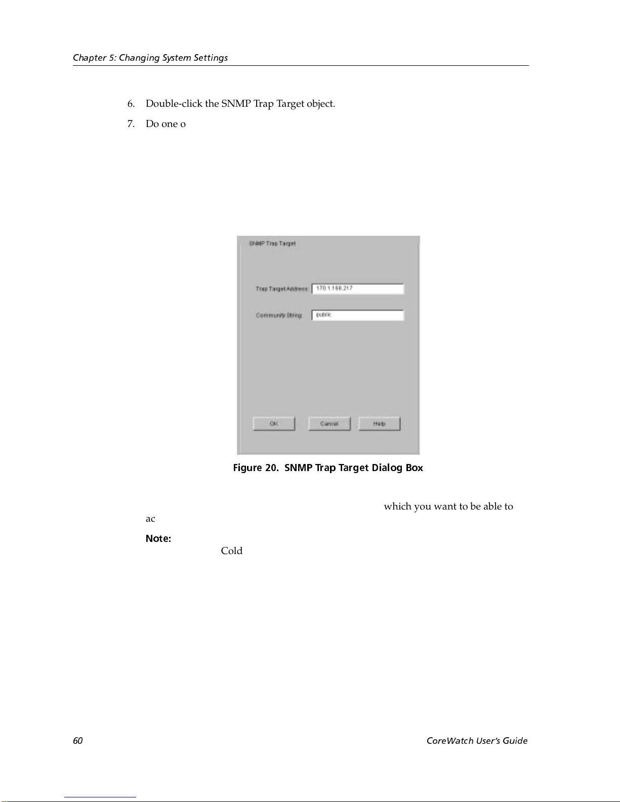
Chapter 5: Changing System Settings
6. Double-click the SNMP Trap Target object.
7. Do one of the following:
– If you are configuring a new trap target, select the Configure New Trap Target
object from the list of trap targets.
– If you are modifying an existing trap target, select it from the list that appeared
after you expanded the SNMP Trap Target object.
An SNMP Trap Target dialog box similar to the following appears:
Figure 20. SNMP Tr ap Target Dialog Box
8. Enter the IP address of the management station from which you want to be able to
access the traps.
Note:
The target IP address should be for a management station locally attached to
the SSR. Cold start traps might not reach their destination if the target
requires dynamic route table entries to be forwarded correctly. The system
will retry for four minutes.
9. In the Community String text box, enter the SNMP community for which you are
setting the trap target.
10. Click OK.
60 CoreWatch Users Guide
Page 61
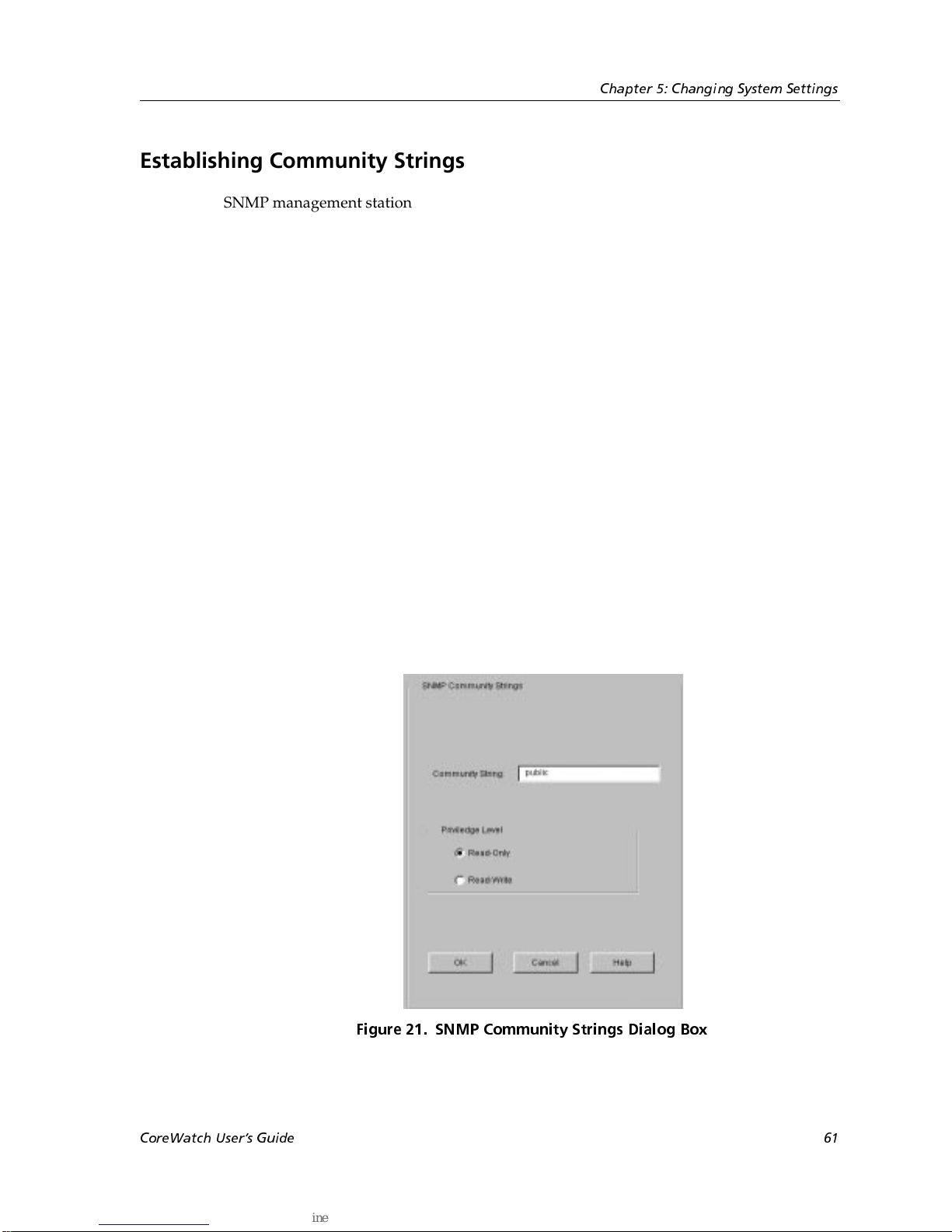
Establishing Community Strings
SNMP management stations that want to access the SSR must supply a community string
that you establish on the SSR. You can establish an SSR community string by specifying
the string’s name and selecting the access privileges for that string. To establish
community strings on the SSR:
1. Start Configuration Expert if you have not already done so.
2. Open the configuration file you want to modify and then double-click that file’s
System Configuration object.
3. Double-click the SNMP Configuration object.
Configuration Expert displays the SNMP Trap Target and SNMP Community String
objects.
4. Double-click the SNMP Community String object.
5. Do one of the following:
– If you are configuring a new community string, select the Configure New
Community String object.
Chapter 5: Changing System Settings
– If you are modifying an existing community string, select it from the list of
community strings that appeared after you expanded the SNMP Community
String object.
An SNMP Community Strings dialog box similar to the following appears:
CoreWatch Users Guide 61
Figure 21. SNMP Community Strings Dialog Box
Page 62
Chapter 5: Changing System Settings
6. In the Community String text box, enter a character string for the community string.
7. Set the level of access to the SSR by selecting one of the options described in the
following table:
Table 8. Level-of-Access Options
Option Description
Read-only Allows SNMP GETs but not SNMP SETs on the SNMP management
stations that access the SSR through the specified community string.
Read-write Allows both SNMP GETs and SNMP SETs on the SNMP management
stations that access the SSR through the specified community string.
8. Click OK.
62 CoreWatch Users Guide
Page 63
Chapter 6
Configuring SSR
Bridging
The SSR provides bridging functions. This chapter
• provides an overview of bridging on an SSR.
• discusses configuring the bridging mode of ports. A port’s bridging mode determines
the contents of that port’s Layer-2 lookup table.
• discusses controlling the aging state of SSR bridging. The SSR’s aging state determines
how long the SSR stores the MAC address information.
• explains setting up the SSR for the Spanning Tree Protocol (STP), which the SSR uses
to work around loops.
A Look at Bridging on the SSR
The SSR uses transparent bridging to link together different segments of an Ethernet
network.
In transparent bridging, the SSR operates as a learning bridge. As such, it monitors traffic
on subnetworks to learn about destination locations, down bridges, traffic congestion, and
other network information. This frees packets from having to carry routing information
and permits the SSR to forward packets based on current network conditions.
As a learning bridge, the SSR stores the source MAC address of each packet it receives.
This permits the SSR to forward future packets destined for a MAC address to be
forwarded to the port on which the source address was found. It does not forward those
packets to other ports, and thus reduces traffic on the network. If the SSR does not
recognize a packet’s MAC address, however, it forwards that packet to every port.
CoreWatch Users Guide 63
Page 64
Chapter 6: Configuring SSR Bridging
Configuring the Bridging Mode of Ports
You can configure ports to use either of the following bridging modes. Each port has a
Layer-2 lookup table where MAC address or flows are stored. A port’s bridging mode
determines the contents of each Layer-2 table entry. A port can use only one type of
bridging at a time.
• Flow-based bridging
If a port is configured for flow-based bridging, each Layer-2 table entry contains
entries consisting of a source MAC address, destination MAC address, and VLAN ID.
• Address-based bridging
If a port is configured for address-based bridging (the default), each Layer-2 table entry
contains a unique destination MAC address and VLAN ID.
Suppose that a port on the SSR is connected to a hub that is connected to three
workstations, A, B, and C. If each workstation is talking to one another and sending
broadcast traffic, the Layer-2 table on the SSR’s port would contain the following entries
for the workstations (assume that the VLAN ID is 1 for all entries):
Table 9. Bridging Modes
Port Configuration Entries
Flow-based bridging • MAC addresses A->B
• MAC addresses A->C
• MAC addresses B->A
• MAC addresses B->C
• MAC addresses C->A
• MAC addresses C->B
• MAC addresses A->broadcast
• MAC addresses B->broadcast
• MAC addresses C->broadcast
Address-based bridging • MAC address A
• MAC address B
• MAC address C
• MAC broadcast address
64 CoreWatch Users Guide
Page 65
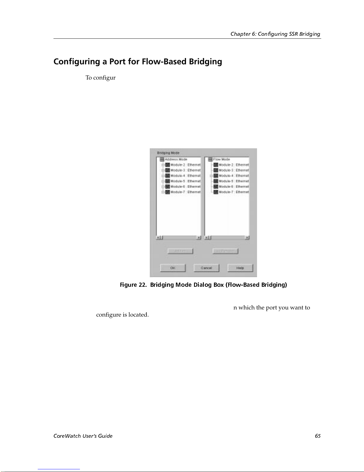
Configuring a Port for Flow-Based Bridging
To configure a port for flow-based bridging:
1. Start Configuration Expert if you have not already done so.
2. Open the configuration file you want to modify and then double-click that file’s
Bridging Configuration object.
3. Double-click the Bridging Mode object.
A Bridging Mode dialog box similar to the following appears:
Chapter 6: Configuring SSR Bridging
Figure 22. Bridging Mode Dialog Box (Flow-Based Bridging)
4. In the Address Mode list, double-click the module on which the port you want to
configure is located. Configuration Expert displays the module’s ports that are
currently using address-based bridging. From the list of ports that appears, select the
port that you want to configure.
CoreWatch Users Guide 65
Page 66
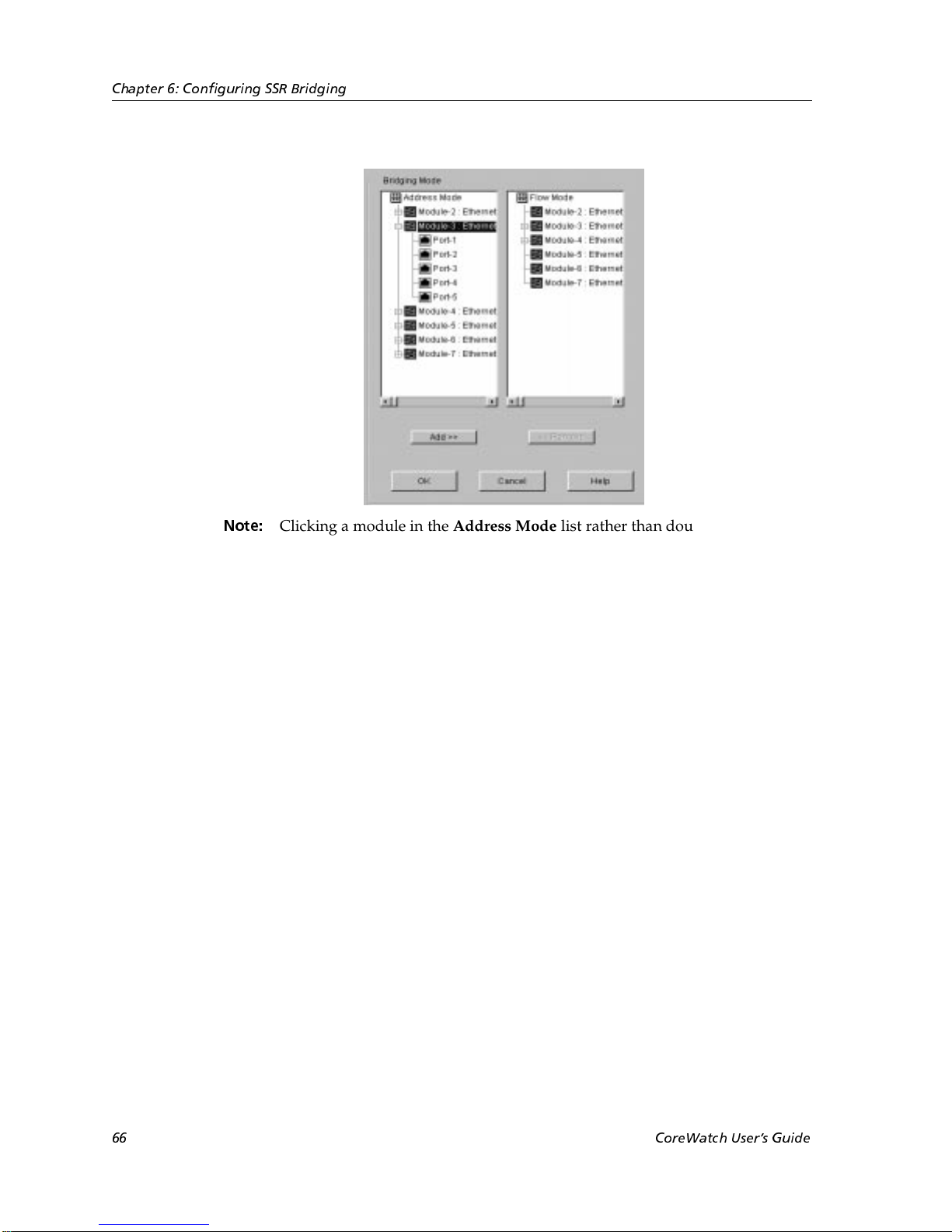
Chapter 6: Configuring SSR Bridging
Note:
5. Click the Add button.
Configuration Expert moves the selected port from the Address Mode list to the
corresponding module in the Flow Mode list.
6. Click OK.
Configuration Expert adds the port to those found in the Flow Mode Bridging object,
which is located in the Bridging Mode object.
Clicking a module in the Address Mode list rather than double-clicking it
selects all of the module’s ports that are currently using address-based
bridging. Use this method if you are configuring all the ports on a module to
use flow-based bridging.
Configuring a Port for Address-Based Bridging
Ports are configured to use address-based bridging by default. If you previously
configured a port for flow-based bridging and later decide you want that port to use
address-based bridging, you can change its bridging mode. To do so, take the following
steps:
1. Start Configuration Expert if you have not already done so.
2. Open the configuration file you want to modify and then double-click that file’s
Bridging Configuration object.
3. Double-click the Bridging Mode object.
A Bridging Mode dialog box similar to the following appears:
66 CoreWatch Users Guide
Page 67
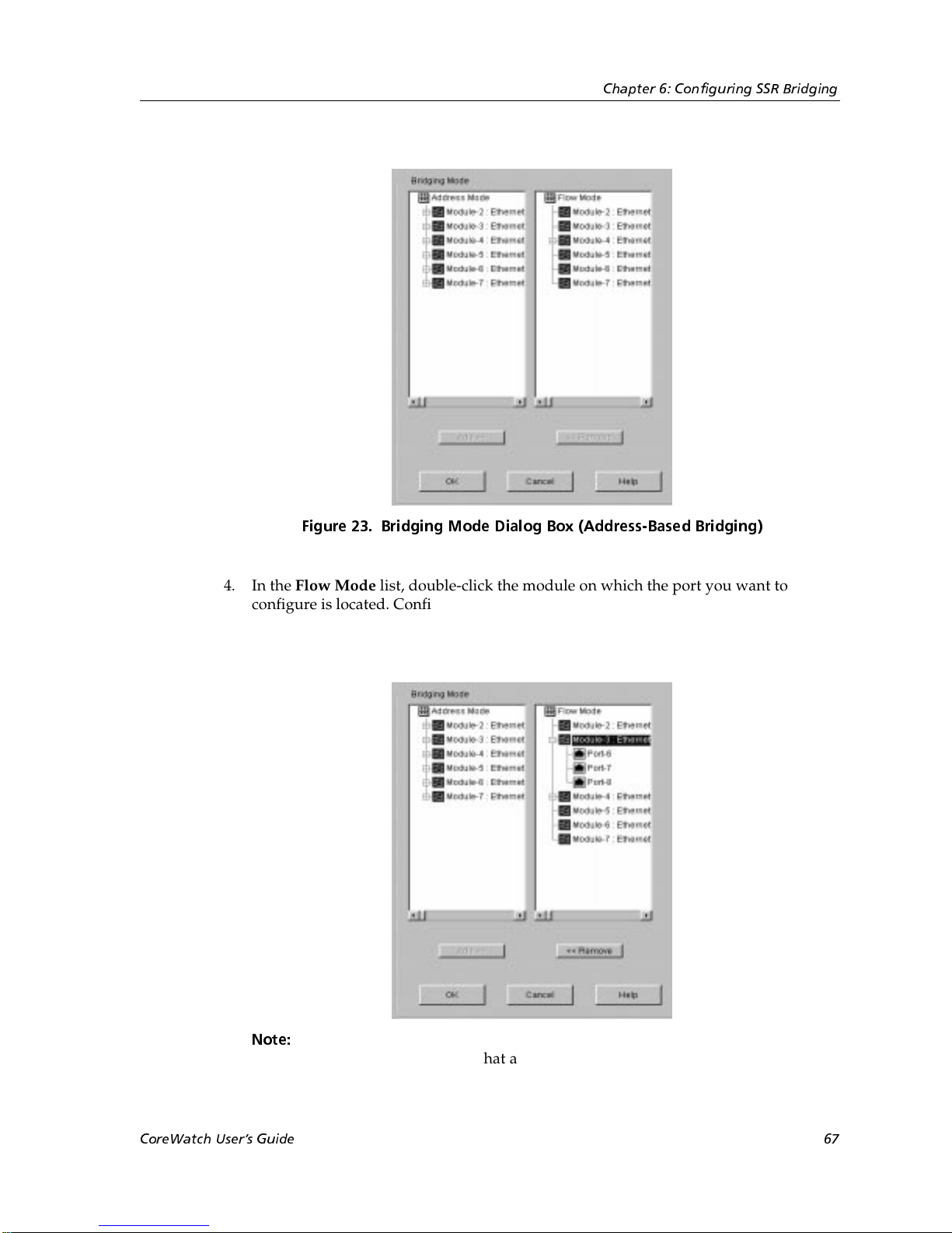
Chapter 6: Configuring SSR Bridging
Figure 23. Bridging Mode Dialog Box (Address-Based Bridging)
4. In the Flow Mode list, double-click the module on which the port you want to
configure is located. Configuration Expert displays the module’s ports that are
currently using flow-based bridging. From the list of ports that appears, select the
port that you want to configure.
Note:
Clicking a module in the Flow Mode list rather than double-clicking it selects
all of the module’s ports that are currently using flow-based bridging. Use
CoreWatch Users Guide 67
Page 68

Chapter 6: Configuring SSR Bridging
this method if you are configuring all the ports on a module to use addressbased bridging.
5. Click the Remove button.
Configuration Expert moves the selected port from the Flow Mode list to the
corresponding module in the Address Mode list box.
6. Click OK.
Configuration Expert adds the port to those found in the Address Mode Bridging
object, which is located in the Bridging Mode object.
Controlling the Aging State of SSR Bridging
The SSR ages learned MAC addresses in the Layer-2 lookup tables. Each port has its own
Layer-2 lookup table. When a learned MAC address entry ages out, the SSR removes that
entry from a port’s Layer-2 lookup tables unless you disable aging on that port.
You can control the aging of learned MAC address entries in the SSR’s Layer-2 lookup
tables. To do so, use Configuration Expert to perform the following tasks:
• Setting up an aging timeout that ports use by default. The SSR uses the aging timeout
to determine how long to keep learned MAC addresses. Aging is a regulation
mechanism the SSR uses to clean up MAC address entries that have not been used for
awhile.
• Overriding the default timeout interval. You do so by setting timeout intervals on any
ports that are to use an interval different from the default aging timeout.
• Disabling aging on a port if you do not want the SSR to remove MAC address entries
from that port’s Layer-2 lookup table.
Separate discussions on each task follow.
Setting Up a Default Aging Timeout
You can set an aging time for learned MAC address entries that all ports use by default.
When the aging time expires for a MAC address, the SSR removes the MAC address from
the port that uses the default timeout. To set up a default aging timeout for MAC address
entries:
1. Start Configuration Expert if you have not already done so.
2. Open the configuration file you want to modify and then double-click that file’s
Bridging Configuration object.
3. Double-click the Aging Configuration object.
4. In the list of aging objects that appears, select the Default Aging Timeout object.
68 CoreWatch Users Guide
Page 69

Chapter 6: Configuring SSR Bridging
A Default Aging Timeout dialog box similar to the following appears:
Figure 24. Default Aging Timeout Dialog Box
5. Enter the number of seconds that the SSR is to allow a learned MAC address to
remain in the Layer-2 lookup table.
You can specify from 15 to 1,000,000 seconds. The default is 300 seconds.
6. Click OK.
Overriding the Default Timeout Interval on a Port
As discussed in “Setting Up a Default Aging Timeout” on page 68, you can set an aging
timeout for learned MAC address entries that ports use by default. You may override this
default timeout if you want a port to use a different timeout interval. To override the
timeout interval on a port:
1. Start Configuration Expert if you have not already done so.
2. Open the configuration file you want to modify and then double-click that file’s
Bridging Configuration object.
3. Double-click the Aging Configuration object.
4. In the list of aging objects that appears, double-click the Aging Timeout Interval
object. Then select the Configure Aging Timeout on a New Port object that appears.
A Set Aging Timeout dialog box similar to the following appears:
CoreWatch Users Guide 69
Page 70
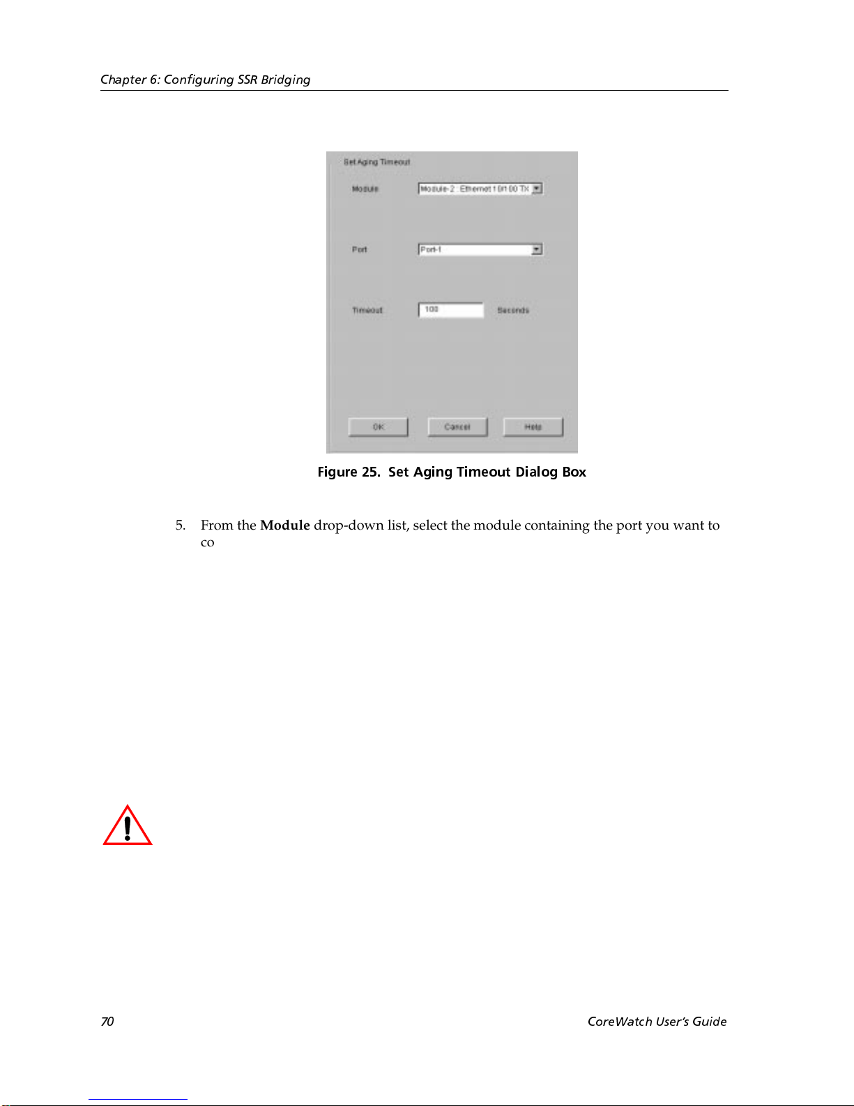
Chapter 6: Configuring SSR Bridging
Figure 25. Set Aging Timeout Dialog Box
5. From the Module drop-down list, select the module containing the port you want to
configure.
6. From the Port drop-down list, select the port you want to configure.
7. In the Tim eout box, enter the number of seconds that the SSR is to allow a learned
MAC address to remain in the Layer-2 lookup table for the specified port.
You can specify from 15 to 1,000,000 seconds. The default is 300 seconds.
8. Click OK.
Disabling Aging on a Port
Disable aging on a port if you do not want the SSR to age MAC address entries in the
port’s Layer-2 lookup tables.
Caution:
to become full because the SSR will not remove MAC addresses from those tables.
To disable aging on a port:
1. Start Configuration Expert if you have not already done so.
2. Open the configuration file you want to modify and then double-click that file’s
Disabling aging on a port may eventually cause the port’s Layer-2 lookup tables
Bridging Configuration object.
3. Double-click the Aging Configuration object.
70 CoreWatch Users Guide
Page 71
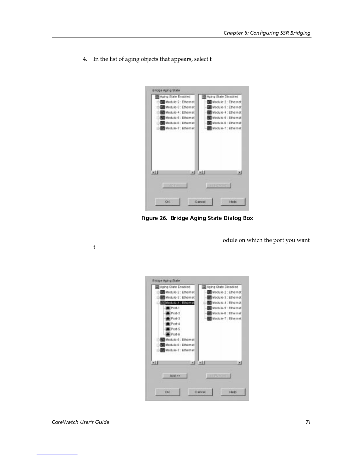
Chapter 6: Configuring SSR Bridging
4. In the list of aging objects that appears, select the Aging State object.
A Bridge Aging State dialog box similar to the following appears:
Figure 26. Bridge Aging State Dialog Box
5. In the Aging State Enabled list, double-click the module on which the port you want
to disable is located. Configuration Expert displays the module’s ports on which
aging is enabled. From the list of ports that appears, select the port on which you want
to disable aging.
CoreWatch Users Guide 71
Page 72

Chapter 6: Configuring SSR Bridging
Note:
6. Click the Add button.
Configuration Expert moves the selected port from the Aging State Enabled list to the
corresponding module in the Aging State Disabled list.
7. Click OK.
Configuration Expert adds the port to those found in the Aging Disabled Ports object,
which is located in the Aging State object.
Clicking a module in the Aging State Enabled list rather than double-clicking
it selects all of the module’s ports on which aging is currently enabled. Use
this method if you want to disable aging on all of those ports.
Enabling Aging on a Port
The SSR removes aged MAC address entries from a port’s Layer-2 lookup table if aging is
enabled on that port. Aging is enabled on all ports by default. Therefore, you do not need
to enable aging on a port unless you previously disabled it and then later decide you want
to enable it on that port again.
To enable aging on a port:
1. Start Configuration Expert if you have not already done so.
2. Open the configuration file you want to modify and then double-click that file’s
Bridging Configuration object.
3. Double-click the Aging Configuration object.
4. In the list of aging objects that appears, select the Aging State object.
A Bridge Aging State dialog box similar to the following appears:
72 CoreWatch Users Guide
Page 73
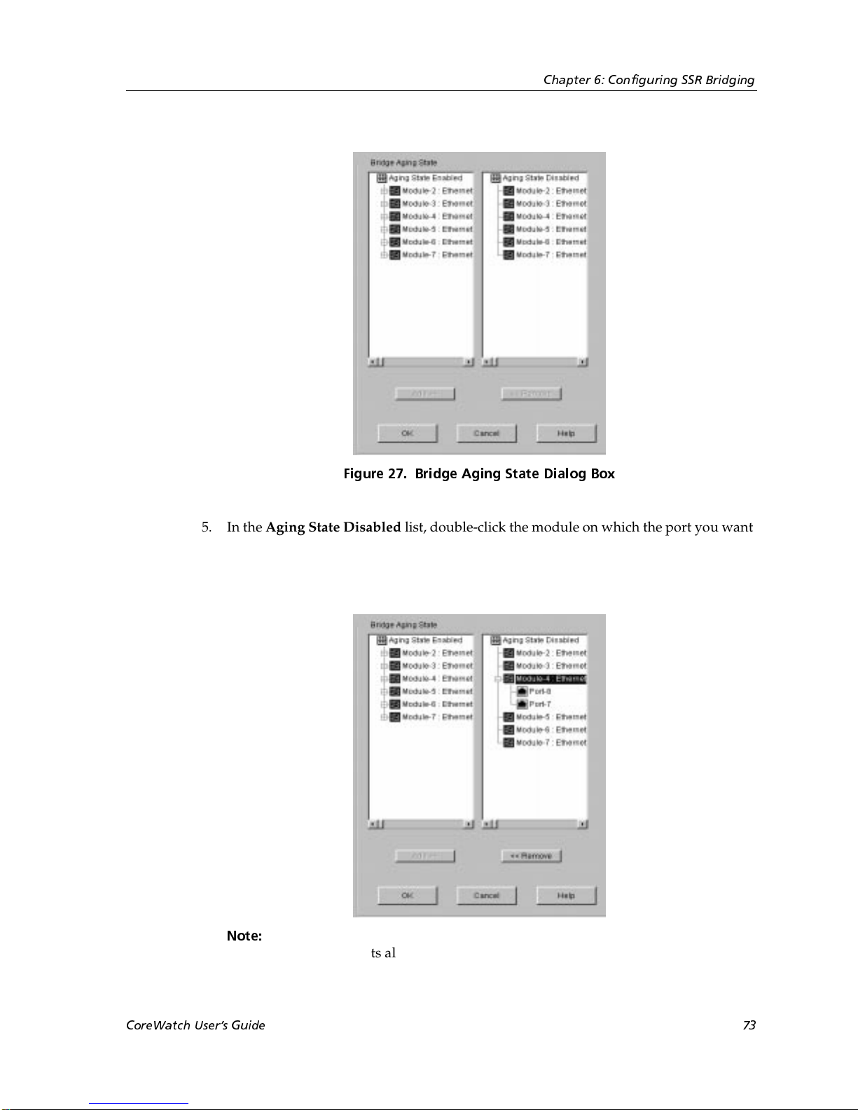
Chapter 6: Configuring SSR Bridging
Figure 27. Bridge Aging State Dialog Box
5. In the Aging State Disabled list, double-click the module on which the port you want
to enable is located. Configuration Expert displays the module’s ports on which aging
is disabled. From the list of ports that appears, select the port on which you want to
enable aging.
Note:
Clicking a module in the Aging State Disabled list rather than double-
clicking it selects all of the module’s ports on which aging is currently
disabled. Use this method if you want to enable aging on all of those ports.
CoreWatch Users Guide 73
Page 74

Chapter 6: Configuring SSR Bridging
6. Click the Remove button.
Configuration Expert moves the selected port from the Aging State Disabled list to the
corresponding module in the Aging State Enabled list.
7. Click OK.
Configuration Expert adds the port to those found in the Aging Enabled Ports object,
which is located in the Aging State object.
Setting Up STP on the SSR
The SSR uses the Spanning Tree Protocol (STP) to dynamically discover a loop-free
topology.
STP includes an algorithm that permits bridges to send Bridge Protocol Data Units
(BPDUs). Unless a bridge is a root bridge, it uses the information in a BPDU to perform
the following operations. (A root bridge is a bridge that uses STP to prevent loops by
periodically exchanging topology information with other bridges.)
1. Select a root bridge.
2. Calculate the shortest path from itself to the root bridge.
3. Select a designated bridge.
A designated bridge is the bridge responsible for forwarding frames to a LAN
segment.
4. Select a root port.
A root port is a port that provides the best path from the bridge to the root bridge.
5. Select which ports are included in a spanning tree.
On the SSR, you can enable STP per port. This approach offers flexibility. STP BPDUs that
arrive on ports on which STP is disabled are forwarded only to ports which are part of the
receiving port's VLAN.
You can set up STP on the SSR by performing the following tasks:
Note:
• Defining STP settings for an SSR bridge.
• Defining STP settings for individual ports.
STP is disabled on the SSR by default. If you want the SSR to use STP, you will
need to define the different settings and enable STP.
• Enabling and disabling STP on individual ports.
Separate discussions on these STP tasks follow.
74 CoreWatch Users Guide
Page 75
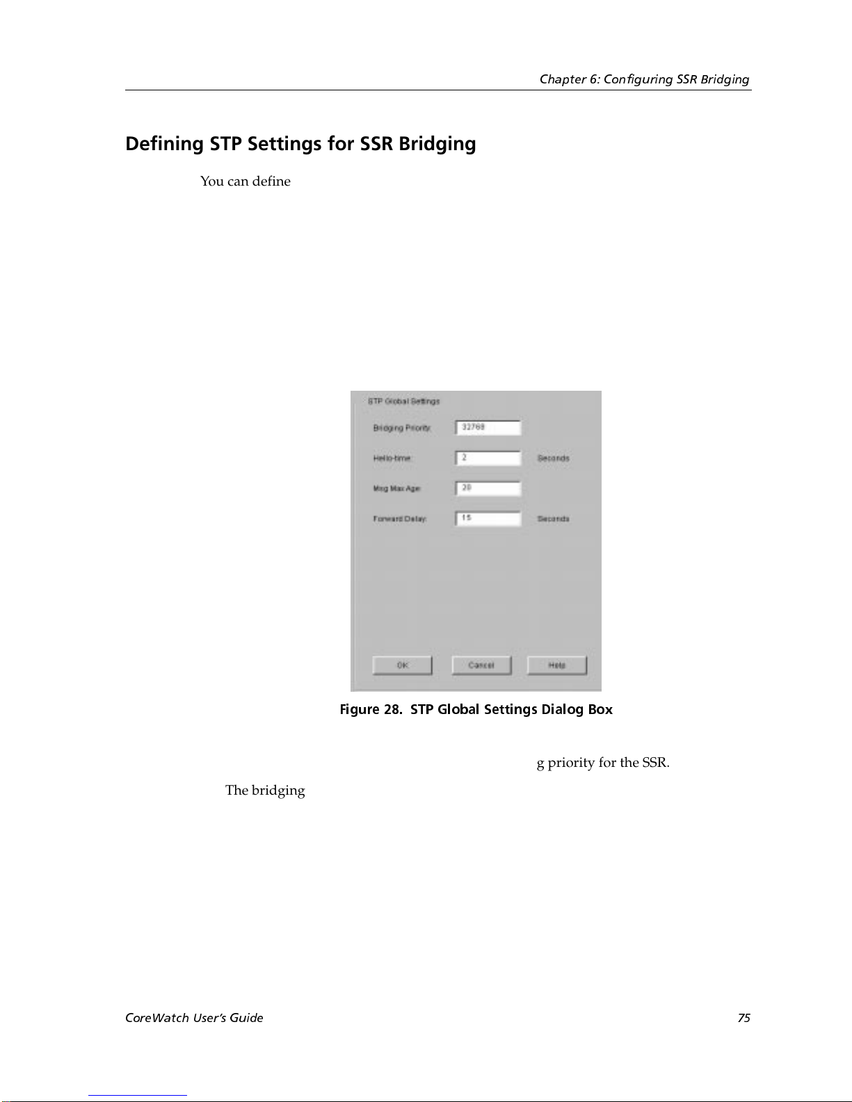
Defining STP Settings for SSR Bridging
You can define global STP settings that the SSR uses for bridging. To define global STP
settings:
1. Start Configuration Expert if you have not already done so.
2. Open the configuration file you want to modify and then double-click that file’s
Bridging Configuration object.
3. Double-click the Spanning Tree Protocol object.
4. In the list of STP objects that appears, select the Global STP Settings object.
An STP Global Settings dialog box similar to the following appears:
Chapter 6: Configuring SSR Bridging
5. In the Bridging Priority box, enter the STP bridging priority for the SSR.
The bridging priority determines which bridge functions as the root bridge. You can
specify a number from 0 to 65535. The bridge assigned the lowest value is the root
bridge. The default is 32768.
6. In the Hello-time box, enter the number of seconds that you want to elapse between
the BPDUs STP sends.
Specify a number from 1to 10. The default is 2.
7. In the Msg Max Age box, enter the number of seconds you want to specify for the
SSR’s maximum age.
CoreWatch Users Guide 75
Figure 28. STP Global Settings Dialog Box
Page 76

Chapter 6: Configuring SSR Bridging
The maximum age is the length of time the SSR keeps the STP-protocol information it
receives. You can specify a number from 6 to 40. The default is 20.
8. In the Forward Delay box, enter the number of seconds you want to elapse between
the transitions of the different STP states.
Specify a number from 4 to 30. The default is 15.
9. Click OK.
The SSR bridge will use the specified STP settings. However, individual ports also have
STP settings that you can configure as discussed in “Defining STP Attributes on an
Individual Port” on page 76.
Defining STP Attributes on an Individual Port
In addition to the global STP settings discussed in “Defining STP Settings for SSR
Bridging” on page 75, the SSR uses the following STP attributes that are set on individual
ports.
•Port priority
The STP algorithm uses the port priority to determine which port to use if a bridge has
two ports connected in a loop.
•Port cost
This attribute specifies how much a port contributes to the total cost of the path to the
root bridge when the port is the root.
A port uses the default settings for these attributes. You may, however, change these
default settings on individual ports. To change a port’s priority or cost:
1. Start Configuration Expert if you have not already done so.
2. Open the configuration file you want to modify and then double-click that file’s
Bridging Configuration object.
3. Double-click the Spanning Tree Protocol object.
4. In the list of STP objects that appears, double-click the Port Specific STP Settings
object.
Configuration Expert displays the Configure New Port object and objects for any
previously configured ports.
5. Do one of the following:
– If you are configuring a port’s STP attributes for the first time, select the Configure
STP Settings on a New Port object.
– If you are modifying existing STP settings of a port, select that port’s object from
the list that appeared after you expanded the Port Specific STP Settings object.
76 CoreWatch Users Guide
Page 77
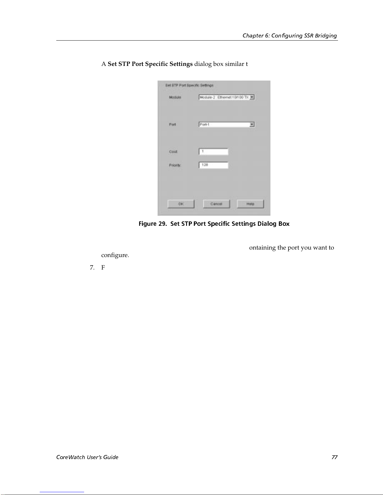
Chapter 6: Configuring SSR Bridging
A Set STP Port Specific Settings dialog box similar to the following appears:
Figure 29. Set STP Port Specific Settings Dialog Box
6. From the Module drop-down list, select the module containing the port you want to
configure.
7. From the Port drop-down list, select the port you want to configure.
8. In the Cost box, enter the STP cost you are assigning to the ports.
Specify a number from 1 to 65535. The default depends on the port speed: 1 for Gigabit
(100-Mbps) ports, 10 for 100-Mbps ports, and 100 for 10-Mbps ports.
9. In the Priority box, enter the priority you want to assign to the port.
Specify a number from 0 to 255. The default is 128.
10. Click OK.
Enabling STP on a Port
Enable STP on a port to eliminate the possibility of there being a loop on that port. To
enable STP on a port:
1. Start Configuration Expert if you have not already done so.
2. Open the configuration file you want to modify and then double-click that file’s
Bridging Configuration object.
3. Double-click the Spanning Tree Protocol object.
CoreWatch Users Guide 77
Page 78
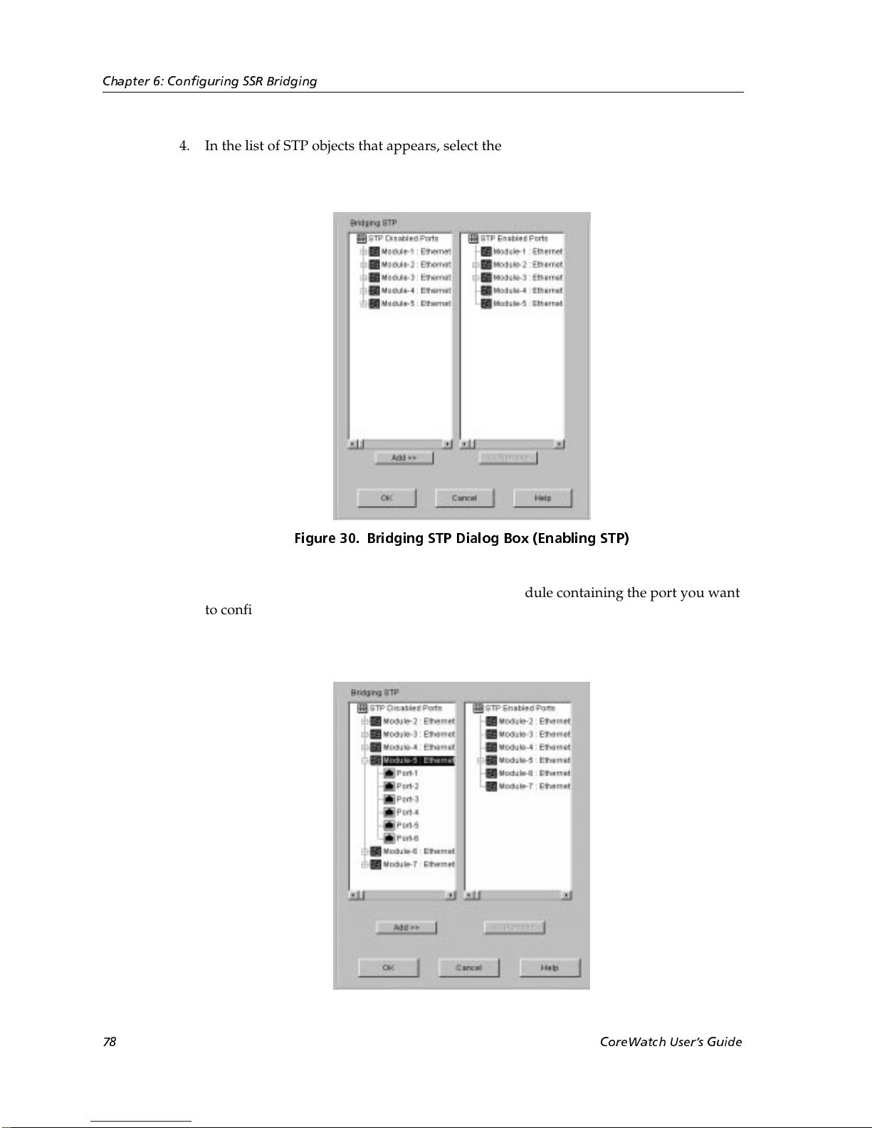
Chapter 6: Configuring SSR Bridging
4. In the list of STP objects that appears, select the STP Port State object.
A Bridging STP dialog box similar to the following appears:
Figure 30. Bridging STP Dialog Box (Enabling STP)
5. In the STP Disabled Ports list, double-click the module containing the port you want
to configure. Configuration Expert displays the module’s ports on which STP is
disabled. From the list of ports that appears, select the port on which you want to
enable STP.
78 CoreWatch Users Guide
Page 79
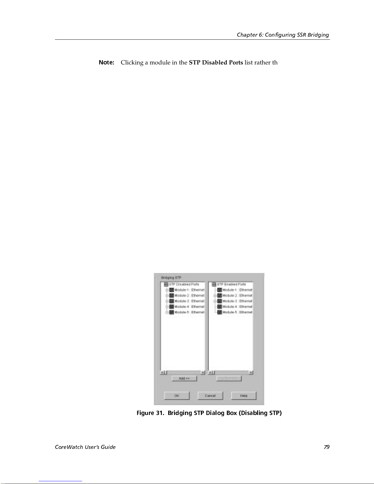
Chapter 6: Configuring SSR Bridging
Note:
6. Click the Add button.
Configuration Expert moves the selected port from the STP Disabled Ports list to the
corresponding module in the STP Enabled Ports list.
7. Click OK.
Configuration Expert adds the port to those found in the STP Enabled Ports object,
which is located in the STP Port State object.
Clicking a module in the STP Disabled Ports list rather than double-clicking
it selects all of the module’s ports on which STP is currently disabled. Use this
method if you want to enable STP on all of those ports.
Disabling STP on a Port
Disable STP on a port if the port does not need to participate in STP. To disable STP on a
port:
1. Start Configuration Expert if you have not already done so.
2. Open the configuration file you want to modify and then double-click that file’s
Bridging Configuration object.
3. Double-click the Spanning Tree Protocol object.
4. In the list of STP objects that appears, select the STP Port State object.
A Bridging STP dialog box similar to the following appears:
Figure 31. Bridging STP Dialog Box (Disabling STP)
CoreWatch Users Guide 79
Page 80
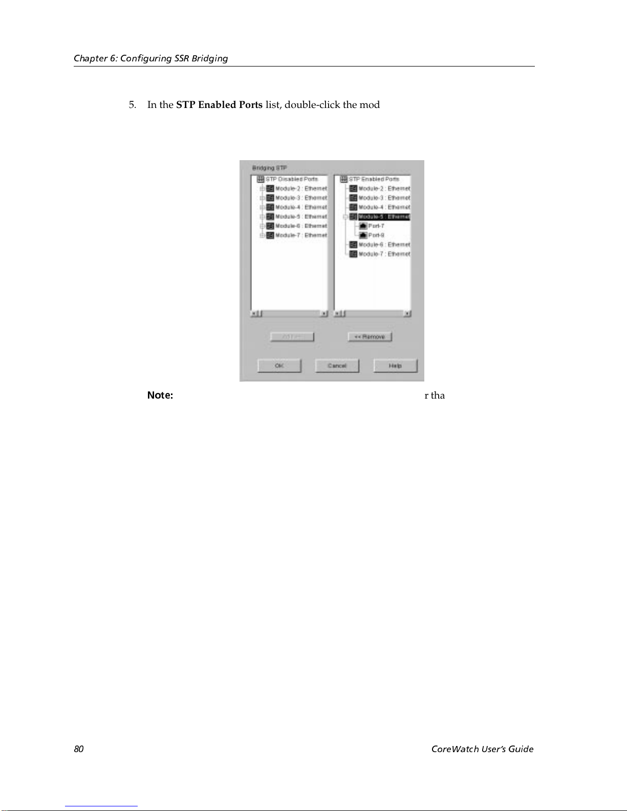
Chapter 6: Configuring SSR Bridging
5. In the STP Enabled Ports list, double-click the module containing the port you want
to configure. Configuration Expert displays the module’s ports on which STP is
enabled. From the list of ports that appears, select the port on which you want to
disable STP.
Note:
Clicking a module in the STP Enabled Ports list rather than double-clicking it
selects all of the module’s ports on which STP is currently enabled. Use this
method if you want to disable STP on all of those ports.
6. Click the Remove button.
Configuration Expert moves the selected port from the STP Enabled Ports list to the
corresponding module in the STP Disabled Ports list.
7. Click OK.
Configuration Expert adds the port to those found in the STP Disabled Ports object,
which is located in the STP Port State object.
80 CoreWatch Users Guide
Page 81
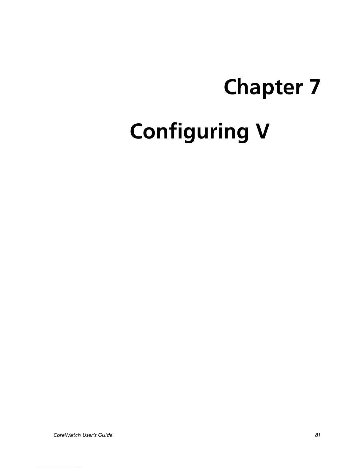
Chapter 7
Configuring VLANs
on the SSR
You configure VLANs to limit the scope of traffic on the SSR. This chapter
• provides an overview of VLANs on the SSR.
• lists tips that make VLAN configuration easy.
• discusses defining ports for VLANs.
• discusses creating the different VLANs the SSR supports.
• describes copying ports to add them to a VLAN.
• discusses modifying VLANs.
A Look at VLANs on the SSR
VLANs contain Layer-2 broadcast and multicast traffic. No traffic is allowed to cross
VLAN boundaries unless it passes through routers. Once connected by routers, VLANs
are equivalent to subnets.
VLANs are created by grouping a set of bridged ports together as part of one bridged
network. Broadcasts from one of the ports in a VLAN are received by other ports in the
group but not by any ports outside of the group. Similarly, unicast traffic is bridged only
between ports in a group but not to ports outside of the group. Thus, traffic is not allowed
to cross the group boundary. A bridge may have multiple VLANs defined thus appearing
as multiple virtual bridges on the SSR.
The SSR supports the following types of VLANs. The VLAN type determines the type of
traffic the SSR will forward on the VLAN.
CoreWatch Users Guide 81
Page 82

Chapter 7: Configuring VLANs on the SSR
• Protocol-based VLAN, which divides the physical network into logical VLANs based
on one or more of the following protocols:
– IP VLAN, which is a VLAN used for IP traffic.
– IPX VLAN, which is a VLAN used for IPX traffic.
– Bridged-protocol VLAN, which is a VLAN used for bridged protocols (such as
AppleTalk).
• Port-based VLAN, which is a VLAN that is independent of the traffic type. Port-based
VLANs treat IP, IPX, and bridged protocols alike.
The ports in a VLAN can be configured as one of the following:
• Access ports
Access ports can belong to only one VLAN per protocol (IP, IPX, or a bridged protocol).
This is the default for all ports.
On access ports, traffic is sent out without 802.1Q frame format.
• Trunk ports
Trunk ports can belong to any number of VLANs. Use trunk ports when you want to
connect SSR routers together and send traffic for multiple VLANs on a single network
segment connecting the routers.
On trunk ports, traffic is always sent out with 802.1Q frame format.
VLAN Configuration Tips
The following list includes tips that you should keep in mind while configuring VLANs
on an SSR as discussed later in this chapter:
• You can quickly add ports to a VLAN, by copying ports as discussed in “Dragging
Ports to Add Them to a VLAN” on page 97.
• When defining trunk ports, you can define all the ports on a module as trunk ports at
one time rather than defining them individually. To do so, click rather than doubleclick the module in the Access Port list box of the dialog box you use to define ports.
Then click the Add button.
• When defining access ports in a dialog box, you can define all the ports on a module as
access ports at one time rather than defining them individually. To do so, click rather
than double-click the module in the Trunk Port list box of the dialog box you use to
define ports. Then click the Remove button.
• When adding ports to a VLAN, you can add all of a module’s available ports at one
time rather than adding them individually. To do so, click rather than double-click the
module in the Available Port List box of the dialog box you use to add ports. Then click
the Add button.
82 CoreWatch Users Guide
Page 83

Chapter 7: Configuring VLANs on the SSR
• When removing ports from a VLAN, you can remove all of a module’s ports at one
time rather than removing them individually.To do so, click rather than double-clock
the module in the Selected Port List box of the dialog box you use to add ports. Then
click the Remove button.
Defining Access Ports and Trunk Ports
You can define ports as either access or trunk ports.
All ports are configured as access ports by default. Therefore, you need to define a port as
an access port only if you previously defined it as a trunk port and now want to use it as
an access port, instead. Access ports can be added to only one VLAN.
Define a port as a trunk port if you want to include that port in multiple VLANs. Trunk
ports are useful for connecting SSRs together and for sending traffic of multiple VLANs
on a single network segment connecting the routers. Suppose you have two
VLANs/subnetworks of IP users on separate SSRs and those VLANs need to belong to
the same layer broadcast domain. You could trunk two SSRs together as shown in the
following figure:
VLAN1 VLAN1
SSR1 SSR2
VLAN2 VLAN2
To define access ports and trunk ports:
1. Start Configuration Expert if you have not already done so.
Note:
2. Open the configuration file you want to modify and then double-click that file’s
Bridging Configuration object.
3. Click the Port Bridging Mode object.
A Bridging VLAN Mode dialog box similar to the following appears:
If you start Configuration Expert from the Schematic view choosing the
Configure VLAN command, Configuration Expert automatically expands
the Active Configuration file’s tree to the VLAN Configuration object. If you
are adding a VLAN to the Active Configuration file, go to step 3.
Trun k
Link
CoreWatch Users Guide 83
Page 84
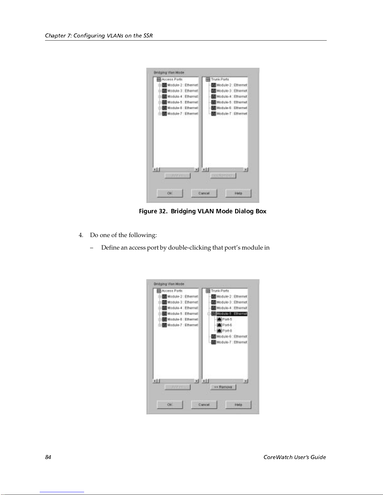
Chapter 7: Configuring VLANs on the SSR
Figure 32. Bridging VLAN Mode Dialog Box
4. Do one of the following:
– Define an access port by double-clicking that port’s module in the Trunk Ports list.
From the list of trunk ports that appears, select the port that you want to define as
an access port. Then click the Remove button.
After you click the Remove button, Configuration Expert moves the selected port from
the Trunk Ports list to the corresponding module in the Access Ports list.
84 CoreWatch Users Guide
Page 85
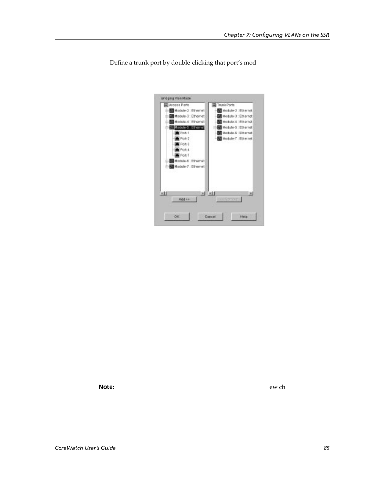
Chapter 7: Configuring VLANs on the SSR
– Define a trunk port by double-clicking that port’s module in the Access Ports list.
From the list of access ports that appears, select the port that you want to define as
a trunk port. Then click the Add button.
After you click the Add button, Configuration Expert moves the selected port from the
Access Ports list to the corresponding module in the Trunk Ports list.
5. Repeat step step 4 until you define all the access and trunk ports you will include in
your VLANs.
Clicking a module rather than double-clicking it in a list box selects all of the module’s
ports in that list box. This is a quick way to select all of module’s ports when you are
defining those ports as all the same type.
6. Click OK.
Configuration Expert adds the access ports and trunk ports to those listed in the Access
Ports and Trunk Ports objects, which are located in the Port Bridging Mode object.
Creating a Protocol-Based VLAN
To create a VLAN that the SSR will use for IP, IPX, or bridged-protocol traffic:
1. Start Configuration Expert if you have not already done so.
Note:
If you start Configuration Expert from the Schematic view choosing the
Configure VLAN command, Configuration Expert automatically expands
the Active Configuration file’s tree to the VLAN Configuration object. If you
are adding a VLAN to the Active Configuration file, go to step 3.
CoreWatch Users Guide 85
Page 86
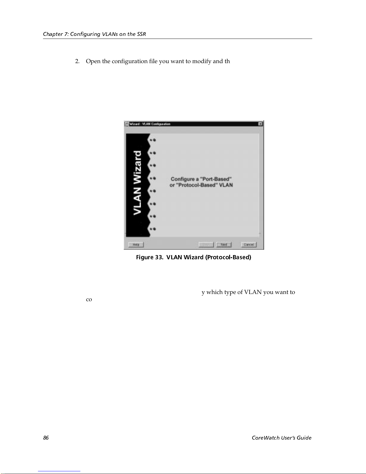
Chapter 7: Configuring VLANs on the SSR
2. Open the configuration file you want to modify and then double-click that file’s
Bridging Configuration object.
3. Double-click the VLAN Configuration object.
4. Click the Configure New VLAN object.
Configuration Expert opens the VLAN wizard.
Figure 33. VLAN Wizard (Protocol-Based)
5. Click Next.
Configuration Expert prompts you to specify which type of VLAN you want to
configure.
86 CoreWatch Users Guide
Page 87
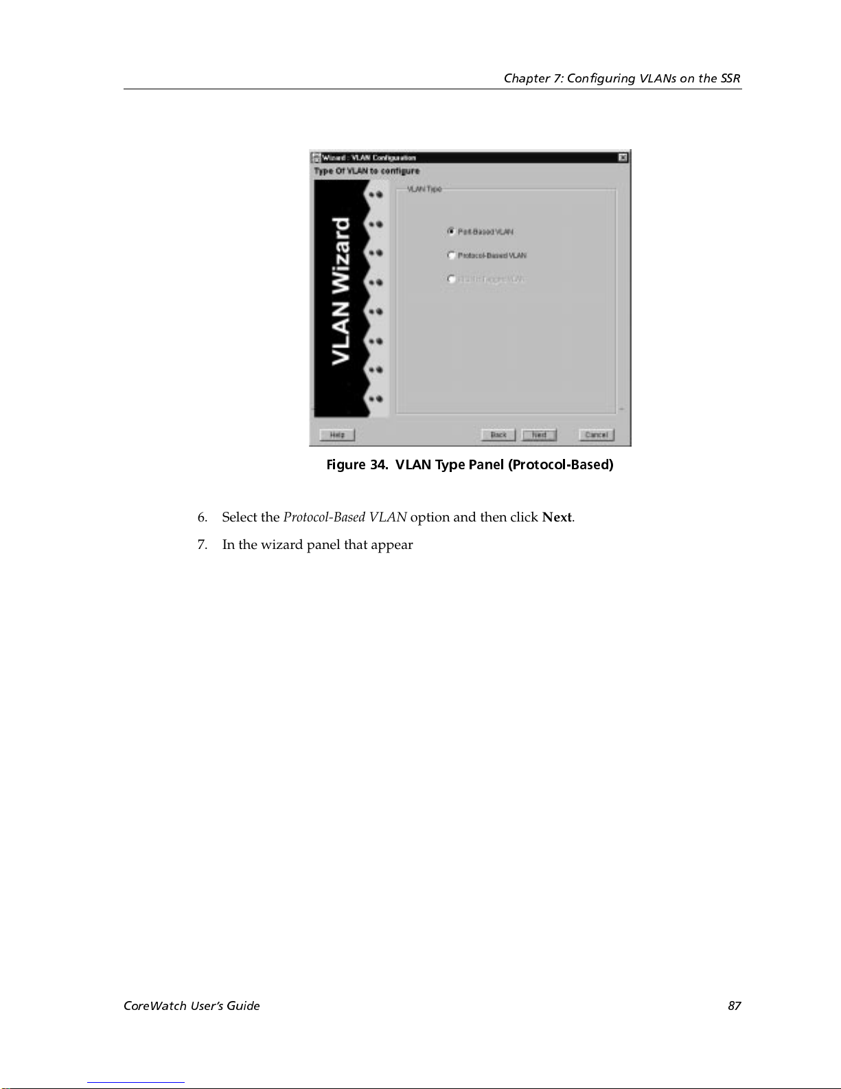
Chapter 7: Configuring VLANs on the SSR
Figure 34. VLAN Type Panel (Protocol-Based)
6. Select the Protocol-Based VLAN option and then click Next.
7. In the wizard panel that appears, define the VLAN by taking the following steps:
a. In the VLAN Name box, enter a name for the VLAN.
The VLAN name is a string up to 32 characters long. You cannot begin a VLAN
name with an underscore ( _ ) or the prefix “SYS_.'
b. In the VLAN ID box, enter an ID number from 2 to 4093 for the VLAN.
The ID you enter must be unique for the VLAN. If you are creating a VLAN that
will be used on two SSRs and you want to connect those SSRs together on the same
trunk port, be sure to use the same ID when creating the VLAN on each SSR. The
SSRs will use the ID to recognize that the same VLAN is configured across two
SSRs.
c. Specify which type of traffic you want to allow on the VLAN. To do so, select one
CoreWatch Users Guide 87
Page 88
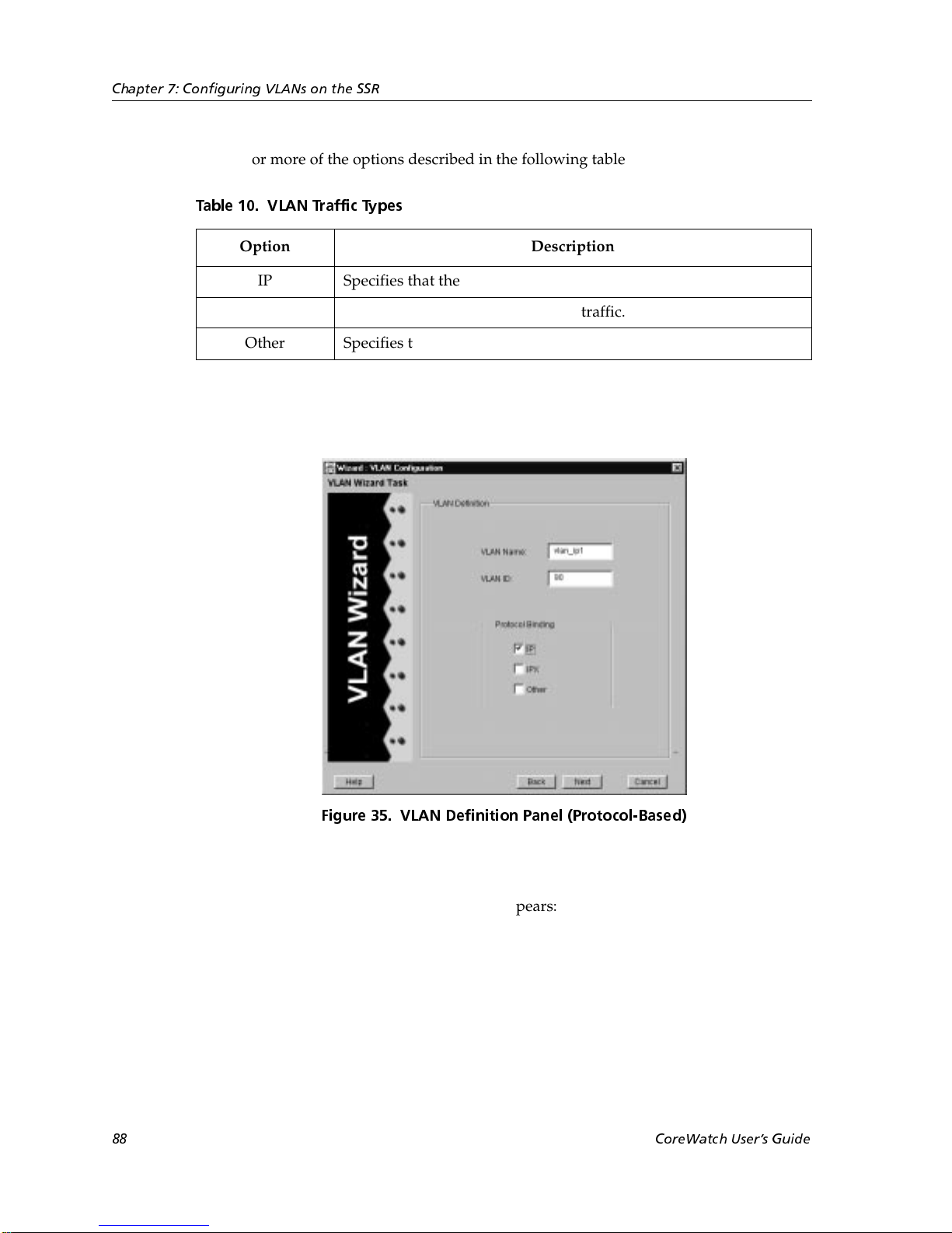
Chapter 7: Configuring VLANs on the SSR
or more of the options described in the following table:
Table 10. VLAN Traffic Types
Option Description
IP Specifies that the VLAN is for IP traffic.
IPX Specifies that the VLAN is for IPX traffic.
Other Specifies that the VLAN is for bridged protocols.
The following figure is an example of the information you enter to define a protocolbased VLAN:
8. Click Next.
A wizard panel similar to the following appears:
88 CoreWatch Users Guide
Figure 35. VLAN Definition Panel (Protocol-Based)
Page 89
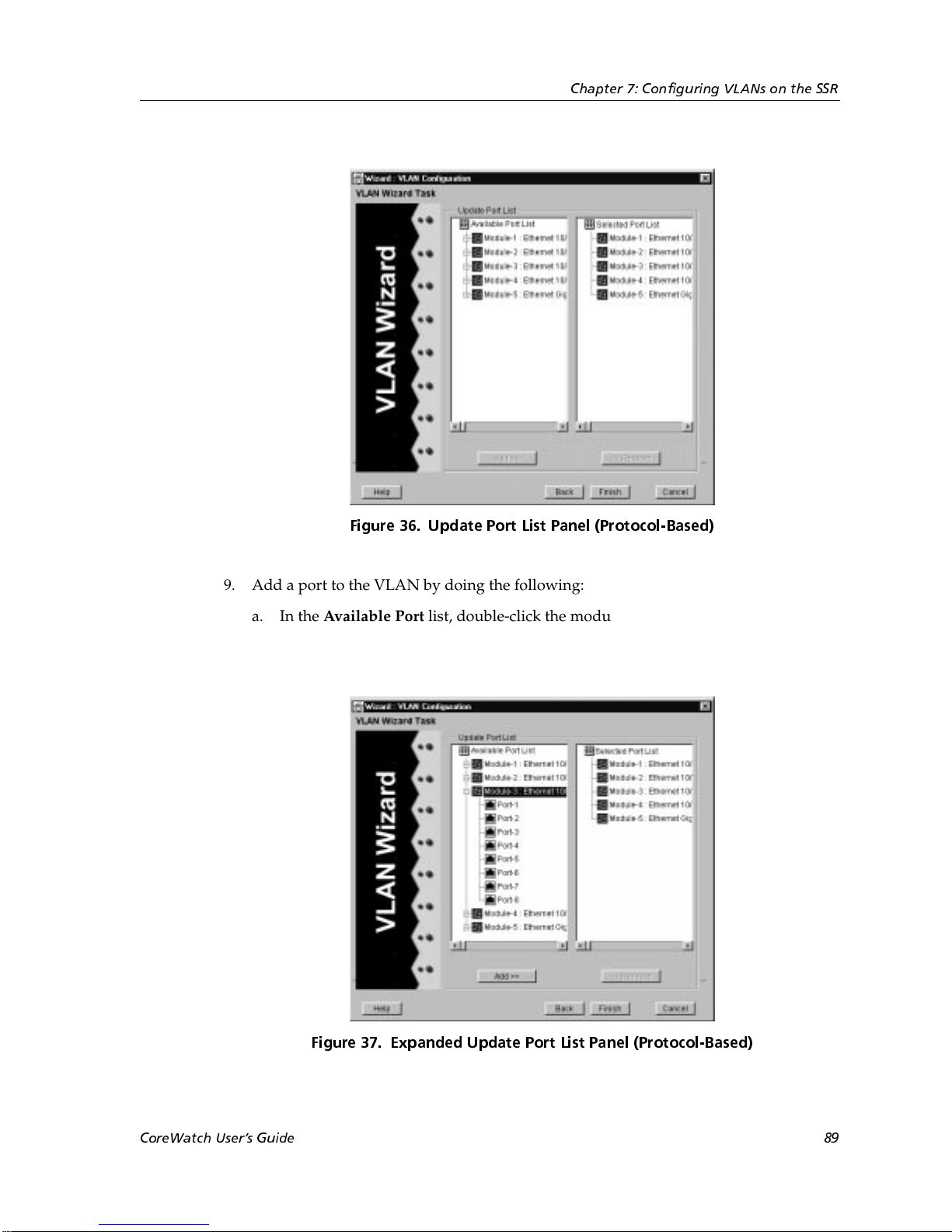
Chapter 7: Configuring VLANs on the SSR
Figure 36. Update Port List Panel (Protocol-Based)
9. Add a port to the VLAN by doing the following:
a. In the Available Port list, double-click the module on which the port you want to
add is located. From the list of available ports that appears, select the port that
you want to add.
Figure 37. Expanded Update Port List Panel (Protocol-Based)
CoreWatch Users Guide 89
Page 90

Chapter 7: Configuring VLANs on the SSR
b. Click the Add button.
Configuration Expert moves the selected port from the Available Port list to the
corresponding module in the Selected Port list.
If you accidentally add a port that you do not want to include in the VLAN, you
may remove it by double-clicking that port’s module in the Selected Port list. From
the list of ports that appears, select the port you do not want in the VLAN. Then
click the Remove button.
10. Continue selecting ports and clicking the Add button until you have added all the
ports you want the VLAN to include.
Clicking a module rather than double-clicking it in a list box selects all of the module’s
ports in that list box. This is a quick way to select all of a module’s ports if you want to
add or remove them all at the same time.
11. Click Finish.
Configuration Expert adds the new VLAN to the VLANs found in the Protocol Based
VLANs object.
Creating a Port-Based VLAN
To create a VLAN that the SSR will use for IP, IPX, and bridged-protocol traffic:
1. Start Configuration Expert if you have not already done so.
Note:
2. Open the configuration file you want to modify and then double-click that file’s
Bridging Configuration object.
3. Double-click the VLAN Configuration object.
4. Click the Configure New VLAN object.
Configuration Expert opens the VLAN wizard.
If you start Configuration Expert from the Schematic view choosing the
Configure VLAN command, Configuration Expert automatically expands
the Active Configuration file’s tree to the VLAN Configuration object. If you
are adding a VLAN to the Active Configuration file, go to step 3.
90 CoreWatch Users Guide
Page 91
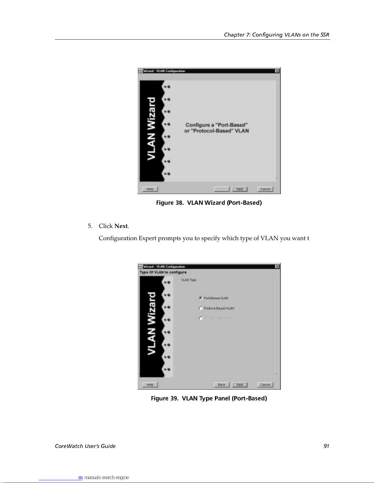
Chapter 7: Configuring VLANs on the SSR
Figure 38. VLAN Wizard (Port-Based)
5. Click Next.
Configuration Expert prompts you to specify which type of VLAN you want to
configure.
Figure 39. VLAN Type Panel (Port-Based)
6. Select the Port-Based VLAN option, then click Next.
CoreWatch Users Guide 91
Page 92
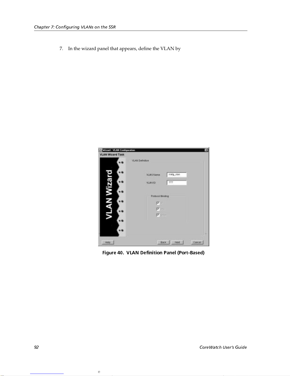
Chapter 7: Configuring VLANs on the SSR
7. In the wizard panel that appears, define the VLAN by taking the following steps:
a. In the VLAN Name box, enter a name for the VLAN.
The VLAN name is a string up to 32 characters long. You cannot begin a VLAN
name with an underscore ( _ ) or the prefix “SYS_.”
b. In the VLAN ID box, enter an ID number from 2 to 4093 for the VLAN.
The ID you enter must be unique for the VLAN. If you are creating a VLAN that
will be used on two SSRs and you want to connect those SSRs together on the same
trunk port, be sure to use the same ID when creating the VLAN on each SSR. The
SSRs will use the ID to recognize that the same VLAN is configured across two
SSRs.
The following figure is an example of the information you enter to define a portbased VLAN:
92 CoreWatch Users Guide
Figure 40. VLAN Definition Panel (Port-Based)
Page 93
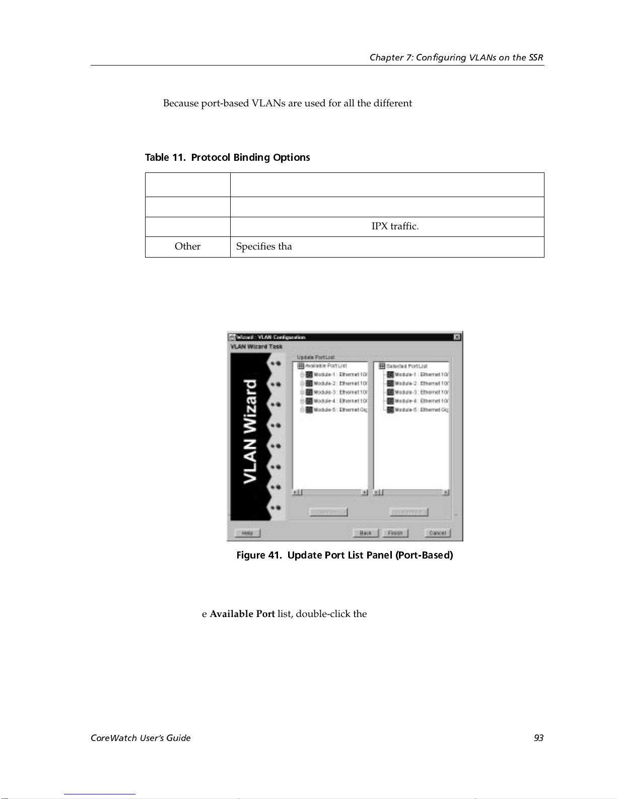
Chapter 7: Configuring VLANs on the SSR
Because port-based VLANs are used for all the different types of protocol traffic,
Configuration Expert automatically selects all the Protocol Binding options described
in the following table. You cannot change these selections.
Table 11. Protocol Binding Options
Option Description
IP Specifies that the VLAN is for IP traffic.
IPX Specifies that the VLAN is for IPX traffic.
Other Specifies that the VLAN is for bridged protocols.
8. Click Next.
A wizard panel similar to the following appears:
9. Add a port to the VLAN by doing the following:
a. In the Available Port list, double-click the module on which the port you want to
add is located. From the list of available ports that appears, select the port that
you want to add.
CoreWatch Users Guide 93
Figure 41. Update Port List Panel (Port-Based)
Page 94
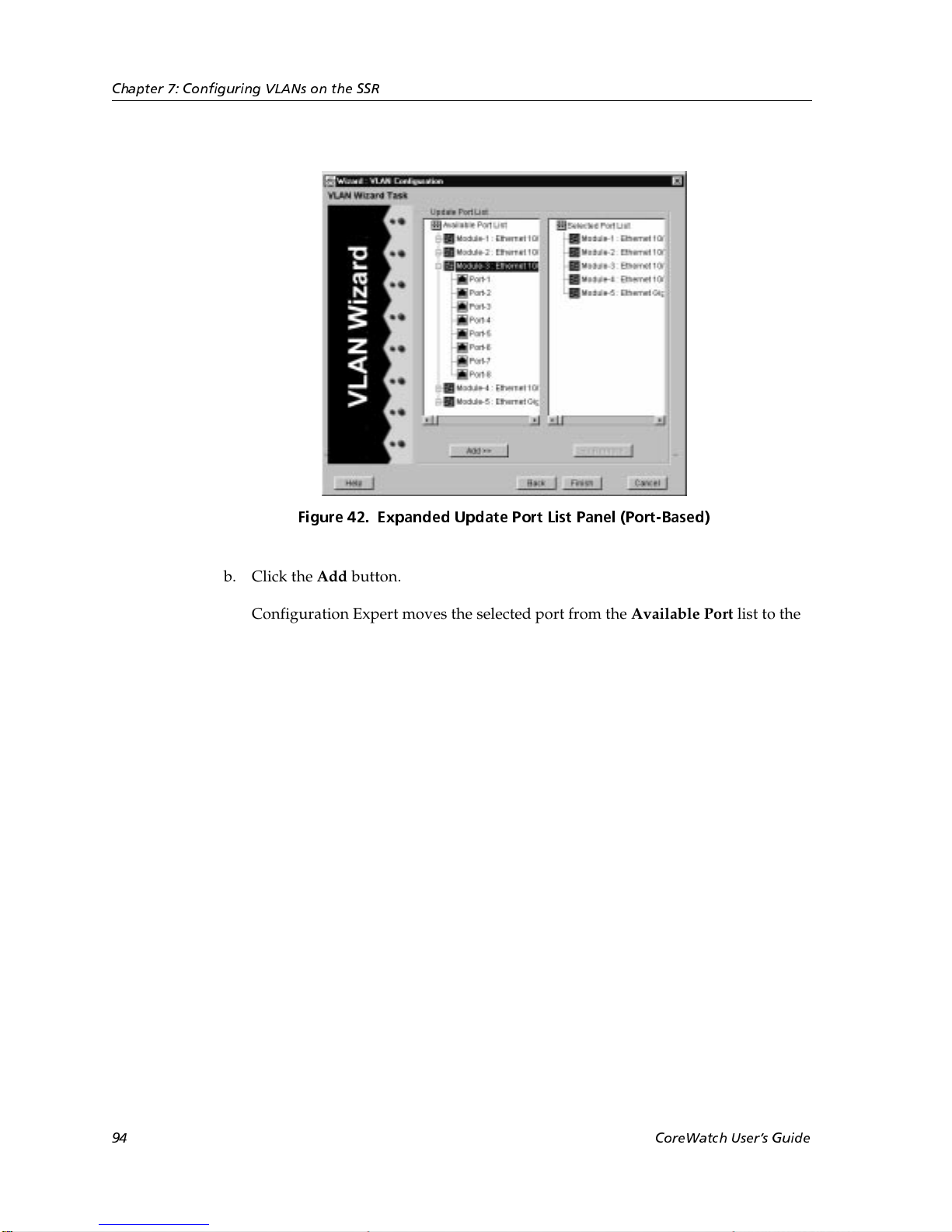
Chapter 7: Configuring VLANs on the SSR
Figure 42. Expanded Update Port List Panel (Port-Based)
b. Click the Add button.
Configuration Expert moves the selected port from the Available Port list to the
corresponding module in the Selected Port list.
If you accidentally add a port that you do not want to include in the VLAN, you
may remove it by double-clicking that port’s module in the Selected Port list. From
the list of ports that appears, select the port you do not want in the VLAN. Then
click the Remove button.
10. Continue selecting ports and clicking the Add button until you have added all the
ports you want the VLAN to include.
Clicking a module rather than double-clicking it in a list box selects all of the module’s
ports in that list box. This is a quick way to select all of a module’s ports if you want to
add or remove them all at the same time.
11. Click Finish.
Configuration Expert adds the new VLAN to the VLANs found in the Port Based
VLANs object.
Modifying VLANs
You can modify any VLAN’s name, ID, and the ports included in a VLAN. On a protocolbased VLAN you can also modify the protocols bound to that VLAN. Separate
94 CoreWatch Users Guide
Page 95
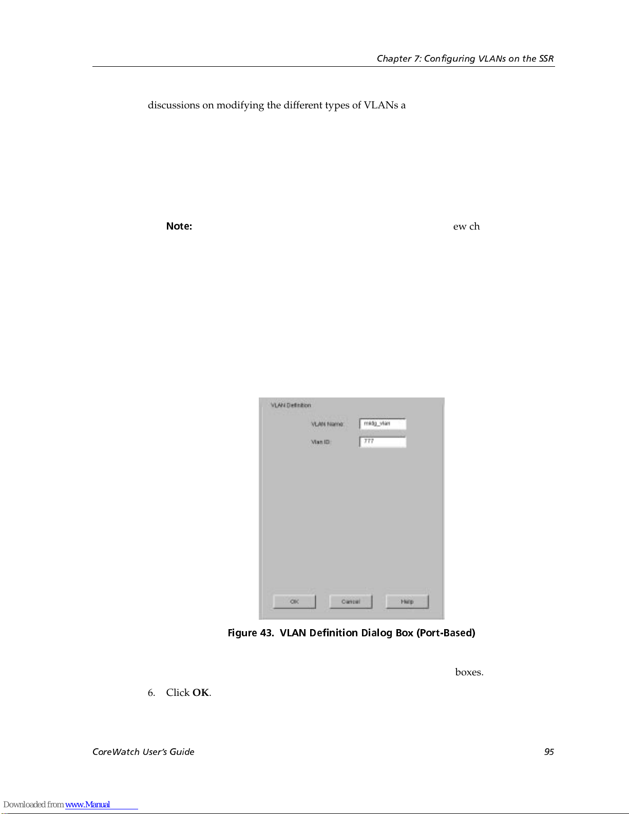
discussions on modifying the different types of VLANs and changing which ports are
included in a VLAN follow.
Changing a Port-Based VLANs Name or ID
To change the name of a port-based VLAN:
1. Start Configuration Expert if you have not already done so.
Chapter 7: Configuring VLANs on the SSR
Note:
2. Open the configuration file you want to modify and then double-click that file’s
Bridging Configuration object.
3. Double-click the VLAN Configuration object.
4. Double-click the Port-Based VLANs object. From the list of VLANs that appears, click
the VLAN you want to modify.
A VLAN Definition dialog box similar to the following appears:
If you start Configuration Expert from the Schematic view choosing the
Configure VLAN command, Configuration Expert automatically expands
the Active Configuration file’s tree to the VLAN Configuration object. If you
are adding a VLAN to the Active Configuration file, go to step 3.
5. Enter the new VLAN name or VLAN ID in the appropriate text boxes.
6. Click OK.
CoreWatch Users Guide 95
Figure 43. VLAN Definition Dialog Box (Port-Based)
Page 96
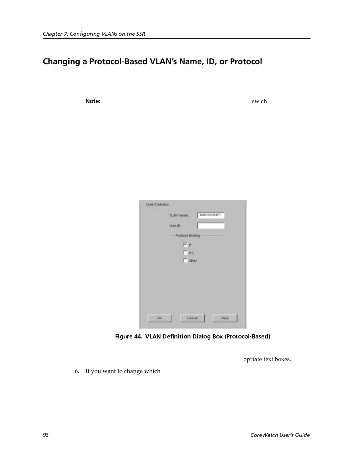
Chapter 7: Configuring VLANs on the SSR
Changing a Protocol-Based VLANs Name, ID, or Protocol Binding
To modify the name, ID, or protocol binding of a protocol-based VLAN:
1. Start Configuration Expert if you have not already done so.
Note:
2. Open the configuration file you want to modify and then double-click that file’s
Bridging Configuration object.
3. Double-click the VLAN Configuration object.
4. Double-click the Protocol-Based VLANs object. From the list of VLANs that appears,
click the VLAN you want to modify.
A VLAN Definition dialog box similar to the following appears:
If you start Configuration Expert from the Schematic view choosing the
Configure VLAN command, Configuration Expert automatically expands
the Active Configuration file’s tree to the VLAN Configuration object. If you
are adding a VLAN to the Active Configuration file, go to step 3.
Figure 44. VLAN Definition Dialog Box (Protocol-Based)
5. If you want to change the VLAN’s name or ID, edit the appropriate text boxes.
6. If you want to change which protocols the VLAN supports, select and clear the
appropriate check boxes.
7. Click OK.
96 CoreWatch Users Guide
Page 97
Replacing an Interfaces VLAN
You can quickly replace an interface’s VLAN with another VLAN. To do so, you either
drag an IP VLAN to an IP interface or an IPX VLAN to an IPX interface.
To replace an interface’s VLAN by dragging a VLAN to the interface:
1. Start Configuration Expert if you have not already done so.
2. Open the configuration file you want to modify and then double-click that file’s
Routing Configuration object.
3. Double-click the IP Routing Configuration object, then do one of the following:
– If you are replacing the VLAN of an IP interface, double-click the IP Interface
Configuration object and then double-click the IP interfaces bound to VLAN
object.
Configuration Expert displays a list of IP interfaces bound to VLANs.
– If you are replacing the VLAN of an IPX interface, double-click the IPX Interface
Configuration object and then double-click the IPX interfaces bound to VLAN
object.
Chapter 7: Configuring VLANs on the SSR
Configuration Expert displays a list of IPX interfaces bound to VLANs.
4. Double-click the Bridging Configuration object, double-click the VLAN Configuration
object and then double-click the Protocol Based VLANs object.
5. Select the VLAN that will be replacing the interface’s existing VLAN.
6. Drag the selected interface to the appropriate interface.
Note:
You can also replace a VLAN by copying it to the interface as discussed in “Copying and
Pasting an Object” on page 44.
You can drag only IP VLANs to IP interfaces, and you can drag only IPX
VLANs to IPX interfaces.
Changing Which Ports a VLAN Includes
Configuration Expert lets you change the ports of a VLAN. You can add ports by dragging
them to the VLAN. You can also add and remove ports using a dialog box. Separate
discussions on each operation follow.
Dragging Ports to Add Them to a VLAN
You can quickly add ports to a VLAN by copying those ports from a port list located
elsewhere in the configuration tree. To do so, take the following steps:
CoreWatch Users Guide 97
Page 98

Chapter 7: Configuring VLANs on the SSR
1. Start Configuration Expert if you have not already done so.
Note:
2. Open the configuration file you want to modify and then double-click that file’s
Bridging Configuration object.
3. Double-click the VLAN Configuration object.
4. Do one of the following:
– If you want to copy ports to a port-based VLAN, double-click the Port Based
– If you want to copy ports to a protocol-based VLAN, double-click the Protocol
5. From the list of VLANs that appears, double-click the VLAN you want to modify and
then double-click that VLAN’s Bound Port List object.
Configuration Expert displays the modules of the ports that are currently included in
the VLAN.
6. Expand the configuration tree until the ports you want to copy appear. You can copy
ports from any port list such as those found in the Chassis Configuration, STP
Enabled, STP Disabled, Access Ports, or Trunk Ports objects.
If you start Configuration Expert from the Schematic view using the
Configure VLAN command, Configuration Expert automatically expands
the Active Configuration file’s tree to the VLAN Configuration object. If you
are adding a VLAN to the Active Configuration file, go to step 3.
VLANs object.
Based VLANs object.
7. Click the port you want to copy. If you want to copy all of a module’s ports, click that
module.
8. Drag the port to the Bound Port List object of the VLAN you want to copy the port to
and release the mouse button when a green check mark appears.
You can also copy the port to the Bound Port List object by using the Copy and Paste
buttons as discussed in “Copying Objects” on page 43.
Adding and Removing a VLANs Ports Through a Dialog Box
To use a dialog box to add or remove ports of a port-based or protocol-based VLAN:
1. Start Configuration Expert if you have not already done so.
Note:
2. Open the configuration file you want to modify and then double-click that file’s
Bridging Configuration object.
3. Double-click the VLAN Configuration object.
If you start Configuration Expert from the Schematic view choosing the
Configure VLAN command, Configuration Expert automatically expands
the Active Configuration file’s tree to the VLAN Configuration object. If you
are adding a VLAN to the Active Configuration file, go to step 3.
98 CoreWatch Users Guide
Page 99

Chapter 7: Configuring VLANs on the SSR
4. Do one of the following:
– If you want to change the ports of a port-based VLAN, double-click the Port Based
VLANs object.
– If you want to change the ports of a protocol-based VLAN, double-click the
Protocol Based VLANs object.
5. From the list of VLANs that appears, double-click the VLAN you want to modify and
then click that VLAN’s Bound Port List object.
A Bound Port List dialog box similar to the following appears:
Figure 45. Bound Port List Dialog Box
6. Add and remove ports from the VLAN as necessary.
– To add a port, double-click that port’s module in the Available Port list. From the
list of ports that appears, select the port you want to add and click the Add button.
Configuration Expert moves the selected port from the Available Port list to the
corresponding module in the Selected Port list.
– To remove a port, double-click that port’s module in the Selected Port list box.
From the list of ports that appears, select the port you want to remove and click the
Remove button.
Configuration Expert moves the selected port from the Selected Port list to the
corresponding module in the Available Port list box.
CoreWatch Users Guide 99
Page 100

Chapter 7: Configuring VLANs on the SSR
Clicking a module rather than double-clicking it in a list box selects all of the
module’s ports in that list box. This is a quick way to select all of a module’s ports
if you want to add or remove them all at the same time.
7. After you add and remove the desired ports, click OK.
100 CoreWatch Users Guide
 Loading...