

Page 1

SmartTrunk
User’s Guide
9032267-04
Page 2

Page 3

Notice
Notice
Cabletron Systems reserves the right to make changes in specifications and other information
contained in this document without prior notice. The reader should in all cases consult Cabletron
Systems to determine whether any such changes have been made.
The hardware, firmware, or software described in this manual is subject to change without notice.
IN NO EVENT SHALL CABLETRON SYSTEMS BE LIABLE FOR ANY INCIDENTAL, INDIRECT,
SPECIAL, OR CONSEQUENTIAL DAMAGES WHATSOEVER (INCLUDING BUT NOT LIMITED
TO LOST PROFITS) ARISING OUT OF OR RELATED TO THIS MANUAL OR THE INFORMATION
CONTAINED IN IT, EVEN IF CABLETRON SYSTEMS HAS BEEN ADVISED OF, KNOWN, OR
SHOULD HAVE KNOWN, THE POSSIBILITY OF SUCH DAMAGES.
© December 1998 by:
Cabletron Systems, Inc.
P.O. Box 5005
Rochester, NH 03867-5005
All Rights Reserved
Printed in the United States of America
Order Number: 9032267-04
Cabletron Systems
SmartMIM-216
All other product names mentioned in this manual may be trademarks or registered trademarks of
their respective companies.
and
FNB
are registered trademarks and
are trademarks of Cabletron Systems, Inc.
SmartSwitch, SmartTrunk
, and
i
Page 4

Notice
FCC Notice
This device complies with Part 15 of the FCC rules. Operation is subject to the following two
conditions: (1) this device may not cause harmful interference, and (2) this device must accept any
interference received, including interference that may cause undesired operation.
NOTE:
device, pursuant to Part 15 of the FCC rules. These limits are designed to provide reasonable
protection against harmful interference when the equipment is operated in a commercial envir onment.
This equipment uses, generates, and can radiate radio frequency energy and if not installed in
accordance with the operator’s manual, may cause harmful interference to radio communications.
Operation of this equipment in a residential area is likely to cause interference in which case the user
will be required to correct the interference at his own expense.
WARNING:
party responsible for compliance could void the user’s authority to operate the equipment.
This equipment has been tested and found to comply with the limits for a Class A digital
Changes or modifications made to this device which are not expressly approved by the
VCCI Notice
This is a Class A product based on the standard of the Voluntary Control Council for Interference by
Information Technology Equipment (VCCI). If this equipment is used in a domestic environment,
radio disturbance may arise. When such trouble occurs, the user may be required to take corrective
actions.
Industry Canada Notice
This digital apparatus does not exceed the Class A limits for radio noise emissions from digital
apparatus set out in the Radio Interference Regulations of the Canadian Department of
Communications.
Le présent appareil numérique n'émet pas de bruits radioélectriques dépassant les limites applicables
aux appareils numériques de la class A prescrites dans le Règlement sur le brouillage radioélectrique
édicté par le ministère des Communications du Canada.
ii
Page 5

Notice
Declaration of Conformity
Addendum
Application of Council Directive(s):
Manufacturer’s Name:
Manufacturer’s Address:
European Representative Name:
European Representative Address:
Conformance to Directive(s)/Product Standards:
Equipment Type/Environment:
We the undersigned, hereby declare, under our sole responsibility, that the equipment packaged with
this notice conforms to the above directives.
89/336/EEC
73/23/EEC
Cabletron Systems, Inc.
35 Industrial Way
PO Box 5005
Rochester, NH 03867
Mr. J. Solari
Cabletron Systems Limited
Nexus House, Newbury Business Park
London Road, Newbury
Berkshire RG13 2PZ, England
EC Directive 89/336/EEC
EC Directive 73/23/EEC
EN 55022
EN 50082-1
EN 60950
Networking Equipment, for use in a
Commercial or Light
Industrial Environment.
Mr. Ronald Fotino Mr. J. Solari
____________________________________________________ ______________________________________________________
Full Name Full Name
Principal Compliance Engineer Managing Director - E.M.E.A.
____________________________________________________ ______________________________________________________
Title Title
Rochester, NH, USA Newbury, Berkshire, England
____________________________________________________ ______________________________________________________
Location Location
iii
Page 6

Notice
iv
Page 7

Chapter 1 Introduction
SmartTrunking............................................................................................................... 1-1
Packet Distribution .......................................................................................................1-2
Compatibility - DEC Hunt Groups and
Chassis with Multiple SmartTrunking Groups.........................................................1-3
SmartTrunk and Port Connections.............................................................................1-4
Getting Help .................................................................................................................. 1-7
Contents
SmartSwitch Router (SSR)....................................................................................1-3
Chapter 2 SmartTrunk Configuration
SmartTrunk Configuration Rules................................................................................2-1
SmartTrunking Configuration Screen........................................................................ 2-3
Exiting the SmartTrunking Configuration Screen............................................. 2-6
Appendix A Helpful Hints for Configuring SmartTrunk
Creating a Second Trunk Group ................................................................................ A-2
Removing an Entire Trunk Group.............................................................................A-3
Removing a Port from a Group..................................................................................A-3
Appendix B MIBII Logical Interface Behavior
Logical/Virtual Port.....................................................................................................B-1
v
Page 8

Contents
vi
Page 9

Introduction
Traditional 802.1D Spanning Tree Bridges only allow one active data path
between any two switches; all other parallel data paths are in Standby or Blocking
mode. If one interface or path should fail, then the other interface automatically
comes out of Blocking mode and forwards all of the traffic. This is fine for
redundancy purposes. However, it is not the most efficient use of resources.
Chapter 1
SmartTrunk, also referred to as SmartTrunking, is Cabletron Systems’
terminology for load balancing or load sharing. SmartTrunk provides the ability
to take full advantage of the network’s redundant bandwidth. SmartTrunk
divides network traffic across multiple ports in parallel to provide additional
throughput. The SmartTrunk application can be used with any of Cabletron
Systems’ switch modules (except ATM modules).
SmartTrunking
A physical port configured in a SmartTrunk Group must:
• Be connected in a point-to-point link (full-duplex is recommended)
• Be connected to a port that is also configured as part of a SmartTrunk Group
• Have Spanning Tree protocol enabled
Whenever a physical port is configured in a SmartTrunk Group, the port will send
proprietary protocol messages (see PLAP and LLAP information in the
Compatibility section). Once the two switches at opposite ends of the link agree
that the trunking state is enabled, the SmartTrunk Group is established. As
additional ports are identified as belonging to the same SmartTrunk Group, the
SmartTrunk Group is automatically reconfigured to take advantage of the
additional paths.
1-1
Page 10

Introduction
Packet Distribution
Packet distribution is based on hardware family type:
SmartSwitch 6000
Packet distribution among the ports in the group is accomplished by adding the
last two bytes of the
the modulus operator to the sum using the number of active ports in the group.
The remainder, which falls into the range of the number of ports in the group, will
dictate which port will be used by the address. This gives a random distribution
of the packet load, but insures that the same destination-source flow always goes
out the same port. This alleviates the possibility of out-of-order packets.
SmartSwitch 9000
Packet distribution is accomplished by applying the modulus operator to the last
four bytes of the
the group. The remainder, which falls into the range of the number of ports in the
group, will dictate which port will be used by the address.
destination and source MAC addresses and then applying
destination MAC addresses using the number of active ports in
Modulus Examples
Ports contained in the trunk are labeled from zer o (0) to one less than the number
of ports in the group. For example, if the physical ports in the group are
1 3 5 7 9, packet distribution would be based on the trunking port number
assigned. Trunking port numbers are 0 1 2 3 4.
The modulus operator divides the first number by the second number and yields
a whole number remainder:
(sum of addresses) modulus (number of trunk ports) = remainder
For example:
5 mod 4 = 1
4 mod 5 = 4 (Five goes into four no times with a remainder of four)
The remainder is the useful number that will fall between zero (0) and one less
than the number of trunk ports. This remainder will dictate which trunk port is
used to send the traffic by matching it to the trunking port number.
(Four goes into five once with a remainder of one)
1-2
Page 11

Compatibility - DEC Hunt Groups and
SmartSwitch Router (SSR)
SmartTrunking for the SmartSwitch 6000 and the SmartSwitch 9000 is based on,
and compatible with, DEC Hunt Groups. With the SSR adopting the DEC Hunt
Groups protocol, this will allow all Cabletron equipment to be trunked to each
other. (See firmware release notes for the compatibility of the individual image
selected.)
SmartTrunking and Hunt Groups are comprised of two protocols:
• Logical Link Aging Protocol (LLAP) - Assists in learning and aging.
• Physical Link Affinity Pr otocol (PLAP) - Monitors and maintains the tr unking
states.
Introduction
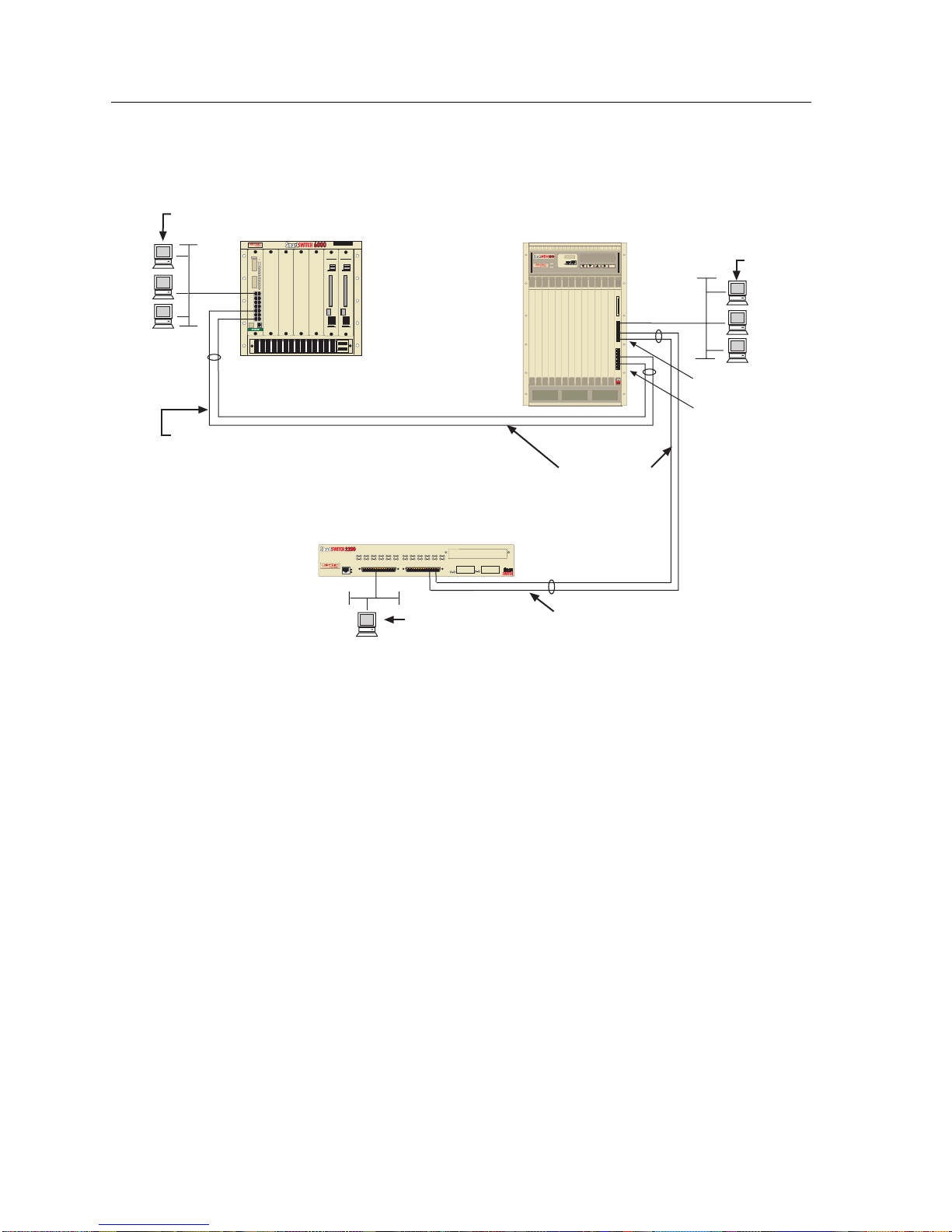
Chassis with Multiple SmartTrunking Groups
Figure 1-1 depicts a simple example of a network using Cabletron devices that
support SmartTrunk. In this example, a module supporting SmartTrunk in a
SmartSwitch 9000 chassis has multiple groups of ports using SmartTrunks. The
SmartSwitch 9000 module acknowledges both the SmartSwitch 6000 module and
the SmartSwitch 2200 chassis. Thus, the SmartSwitch 9000 module has “multiple
groups,” when viewing LM and NMS (Network Management Software) screens.
A group is defined as a trunk connection between a chassis and/or a standalone
switch. In Figure 1-1, the 2200 and 6000 each have one group of trunking with two
ports. The 9000 module has two groups with two ports in each instance.
SmartTrunk can be configured in a number of different ways. Links can be made
from multiple ports on a standalone SmartSwitch to one or more standalone or
individual chassis-based SmartSwitches. When trunking from a standalone
switch to a chassis-based switch, the trunk ports need to be connected to the same
board in the chassis.
1-3
Page 12
Introduction
Users
SmartSwitch 6000
Chassis
MIM
-216Smart
Group B on the
SmartSwitch 6000 Module
SmartSwitch 9000
9C106
Chassis
Users
9H422-12
Group A
Group B
Both Groups
on the
SmartSwitch 9000
SmartSwitch 2200
PWR
CPU
2E43-27
COM
Users
Group A on the
SmartSwitch 2200
Figure 1-1. Chassis with Multiple SmartTrunk Groups Enabled
SmartTrunk and Port Connections
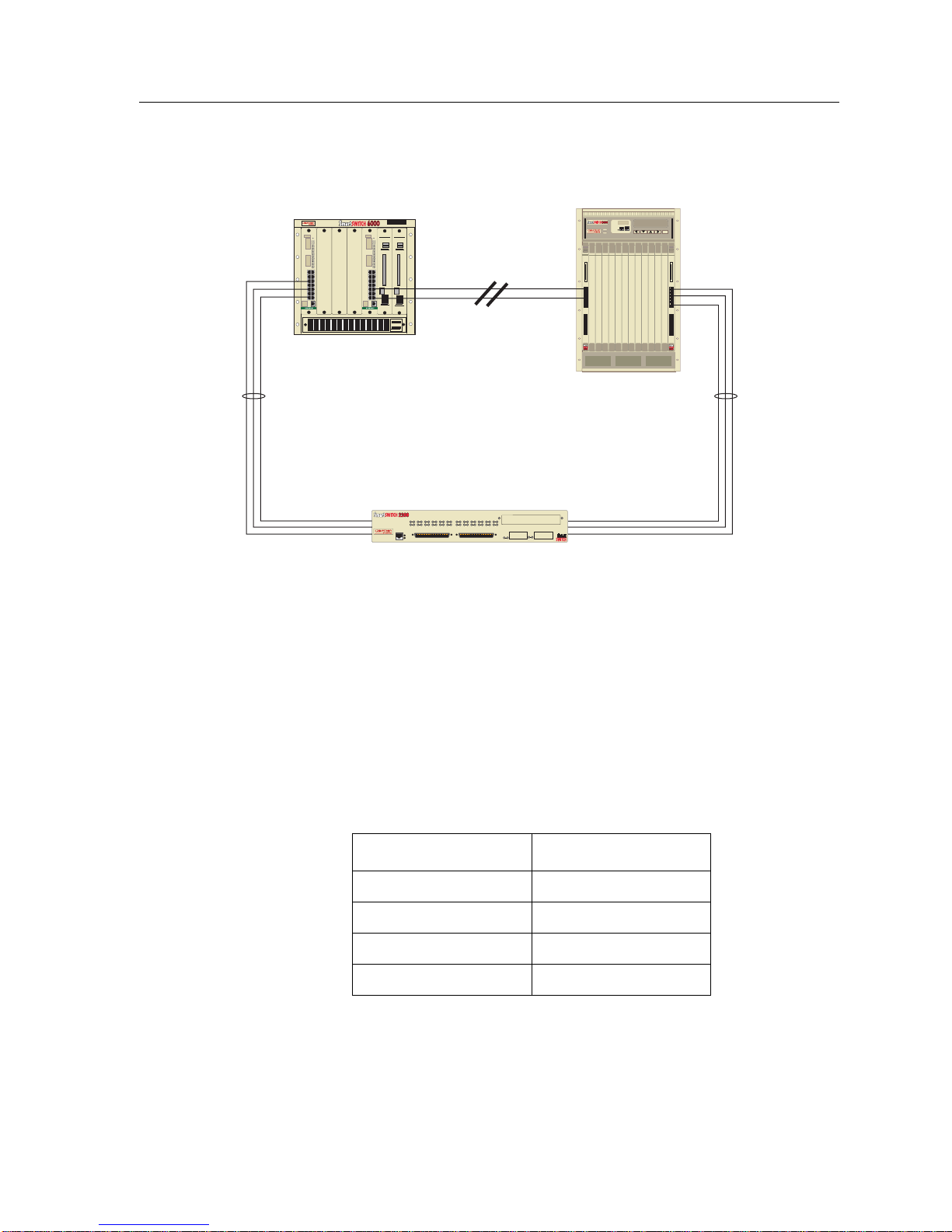
The SmartTrunk application dynamically determines network loops and is used
concurrently with the Spanning Tree protocol. The SmartTrunk application only
acknowledges its neighboring switches. If a user goes through several switch
hops, then loops back to the first switch hop (creating a loop), a common
connection between two switches (any two) will go into a Blocking state (see
Figure 1-2).
1-4
Page 13
Introduction
SmartSwitch 6000
Chassis
MIM
-216Smart
9C106
MIM
-216Smart
SmartSwitch 9000
Chassis
SmartTrunk
connections
blocked
SmartSwitch 2200
PWR
CPU
2E43-27
COM
Figure 1-2. SmartTrunk with a Network Loop
Path costs are considered by SmartTrunk when disabling a looped configuration.
SmartTrunk will place the higher path cost trunk group into a Blocking state.
Path cost will be calculated using the following equations:
Speed
The speed of the interface (typically in megabits). For example, 10, 100, or 1000
(see Table 1-1).
Table 1-1. Example Path Costs
Port Type Path Cost
10 Mb, Half Duplex 100
10 Mb, Full Duplex 50
100 Mb, Half Duplex 10
100 Mb, Full Duplex 5
1-5
Page 14
Introduction
Active T runk Links
The number of links participating in the trunking group.
If all the ports in the trunking group are the same speed and configured to the
same duplex mode, the equation is:
1000
------
Path Cost x # of ports
If the ports in the trunking group are different speeds, the equation is:
1000
------
Path Cost 1 + Path Cost 2 + Path Cost 3 + Path Cost n...
Trunking
(Active)
SmartSwitch 9000
Chassis
9H422-12 9H422-12
Blocked
2
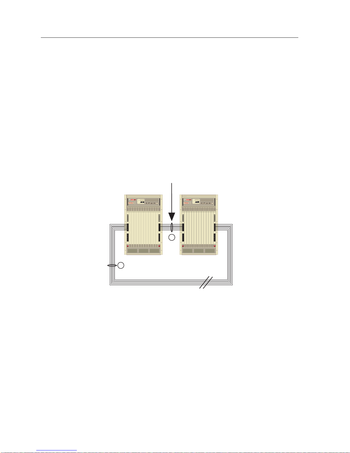
The active path is determined by
the lowest combined path cost.
The higher path cost ports will be blocked.
Figure 1-3. A Redundant Standby Path for Trunking
SmartSwitch 9000
Chassis
1
Multiple trunks can also be established between chassis-based switches, but only
one group of trunk ports will be active. The trunked ports do not necessarily need
to be on the same module. A Blocking state for all ports in the Group in Standby
will be reflected on the SmartTrunking Local Management screen. In some cases,
the INB backplane will block.
1-6
Page 15

NOTES
Introduction
When this configuration is used, only one module’s SmartTrunk Group will be
active. The second path will block and serve as a backup to the currently active
path. (The active trunking path will be determined by the module providing the
lowest path cost.)
Refer to the release notes for image-specific restrictions while using
SmartTrunking.
The only time path cost is calculated is when a port is added or removed from the
trunking group. While the trunking group is operational, losses of link or PLAP
on a port will not result in path cost recalculation. In order for a redundant gr oup
to become active, the entire primary group must become inactive or disabled.
Getting Help
For additional support related to this device or document, contact Cabletron
Systems using one of the following methods:
World Wide Web http://www.cabletron.com/
Phone (603) 332-9400
Internet mail [email protected]
FTP ftp://ftp.cabletron.com/
Login anonymous
Password your email address
To send comments or suggestions concerning this document, contact
the Cabletron Systems Technical Writing Department via the following
email address:
Make sure to include the document Part Number in the email message.
Before calling Cabletron Systems, have the following information ready:
• Your Cabletron Systems service contract number
• A description of the failure
• A description of any action(s) already taken to resolve the problem (e.g.,
changing mode switches, rebooting the unit, etc.)
• The serial and revision numbers of all involved Cabletron Systems products in
the network
• A description of your network environment (layout, cable type, etc.)
• Network load and frame size at the time of trouble (if known)
1-7
Page 16

Introduction
• The device history (i.e., have you returned the device before, is this a recurring
problem, etc.)
• Any previous Return Material Authorization (RMA) numbers
1-8
Page 17

SmartTrunk Configuration
Prior to entering information in the SmartTrunking Configuration Screen, you
should understand the concept of SmartTrunk (see Chapter 1) and the
SmartTrunk Configuration Rules.
Chapter 2
SmartTrunk Configuration Rules
The following rules apply when configuring ports for SmartTrunking.
NOTE
Failure to follow these rules will produce poor network performance.
1. There is a limit of six (6) SmartTrunk groups per switch. There are no port
number restrictions per group.
2. SmartTrunking ports should be configured to Full Duplex.
3. You cannot loop front panel ports back to the same module, to the same
chassis, or to different modules within that chassis.
4. You must enable Spanning Tree before you enable SmartTrunk If a network
loop exists and SmartTrunk becomes disabled, then as long as Spanning Tree
is enabled, the Spanning Tree algorithm will respond and block the necessary
ports.
5. If a network loop exists and SmartTrunk becomes disabled, and Spanning
Tree is also disabled, then an infinite packet loop may occur and adversely
affect the network.
6. If a SmartTrunking port becomes unusable, all traffic is redirected over the
remaining port(s) in the group.
2-1
Page 18
SmartTrunk Configuration
7. Backplane ports (INB, FNB, FTM, etc.) on chassis-based switches cannot be
configured as SmartTrunk ports and are not eligible to participate in trunking.
8. An end station plugged directly into a port configured for SmartTrunking will
not be allowed to communicate. No traffic will flow into the port.
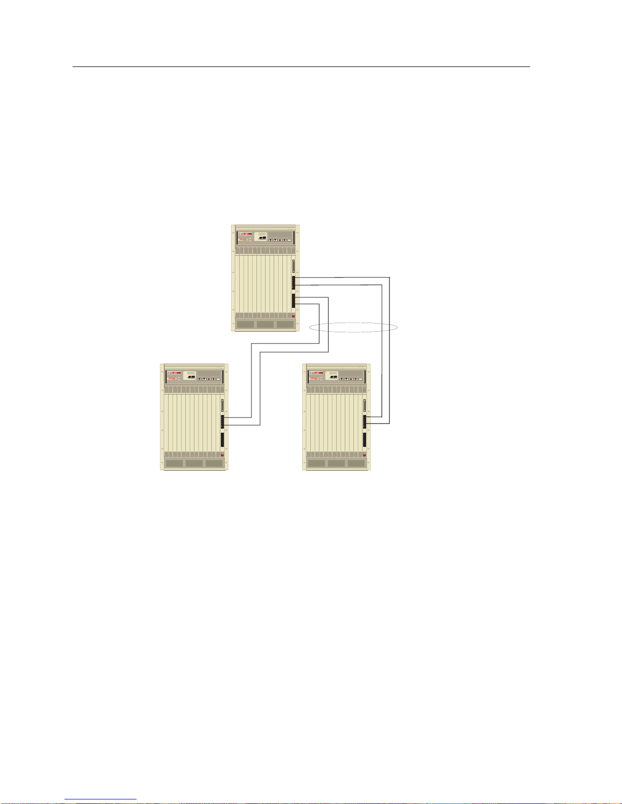
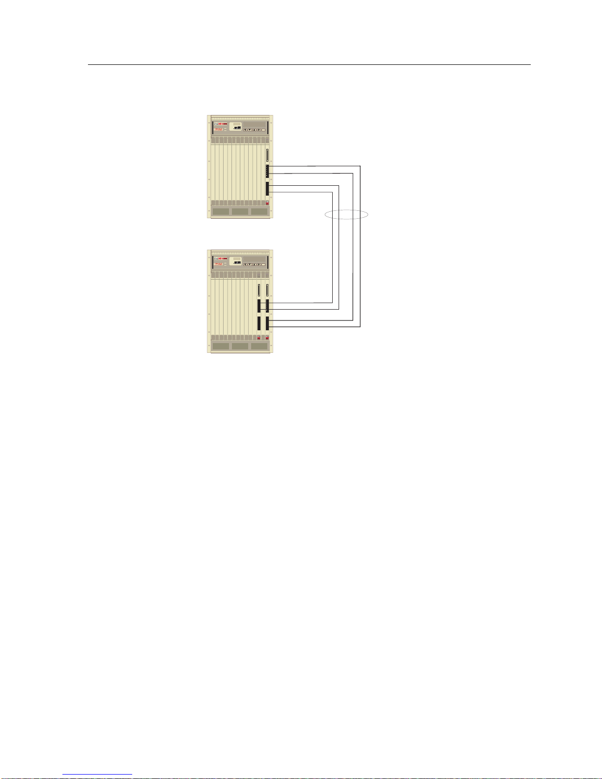
9. The same SmartTrunk group
Figures 2-1 and 2-2).
9H422-12
cannot be split onto two separate modules (see
Group A
9H422-129H422-12
2-2
Figure 2-1. ILLEGAL CONFIGURATION (Example 1)
Page 19
SmartTrunk Configuration
9H422-12
Group A
9H422-12
Figure 2-2. ILLEGAL CONFIGURATION (Example 2)
SmartTrunking Configuration Screen
To select the SmartTrunking Configuration Screen from the Module
Configuration Menu:
1. Use the arrow keys to highlight the SmartTrunking Configuration option.
2. Press the
displays.
ENTER key. The SmartTrunking Configuration Screen, Figure 2-3,
2-3
Page 20

SmartTrunk Configuration
Device Type: 2E42-27 Firmware Revision: XX.XX.XX
SmartTrunk Group:
SmartTrunk Logical Port:
Port State Port State Port State
---------------- ----------------- -----------------
2E42-27 LOCAL MANAGEMENT
SmartTrunking Configuration
BOOTPROM Revision: XX.XX.XX
SmartTrunk State: [ENABLED] Trunk Protocol: [ENABLED]
Add/Remove Group: Group: [ ADD ]
Display Group: Port: [REMOVE]
SAVE UPDATE EXIT RETURN
Figure 2-3. SmartTrunking Configuration Screen
The following section briefly explains each field on the SmartTrunking
Configuration Screen.
SmartTrunk Group
The title of the group that is active in the screen.
SmartTrunk Logical Port
SmartTrunk ports are a collection of physical ports. When the logical port is not
one of the physical ports contained in the group, a MIBII interface is created to
represent the Trunk group. These interfaces are added dynamically as each new
hunt group is created (see Appendix A for more information).
If the logical port is one of the physical ports, then it identifies the bridge port
number used by all members of the SmartTrunking group.
The interface gets its MAC address from the management port of the SmartTrunk
(usually the first port added). If this port is removed from the trunk, the next
port’s MAC address will be assigned to the interface.
2-4
Page 21

SmartTrunk Configuration
SmartTrunk State (Toggle)
Used to enable or disable SmartTrunking for all groups defined on the device.
• ENABLE - Select to change state to On
• ENABLED - Currently On
• DISABLE - Select to change state to Off
• DISABLED - Currently Off
Add/Remove Group
Is either of the following:
• ADD - Creates a SmartT r unk Group Name. The name field will become empty,
awaiting user input.
• DELETE - Removes the SmartTrunk Group Name. The name field will
automatically fill with SmartTrunk names found on the device. Users may
either type in the name to be deleted or use the SmartT runk Gr oup field to step
through the list of names found on the switch.
NOTE
Display Group
A list of the SmartTrunk groups available on this device. Selecting a group
updates the table in the center of the screen. The table displays the ports and
current state of the members included in the group. If no groups have been
created (Added), then this field will remain blank and the table will display no
data.
Trunk Protocol (Optional)
To trunk with third party products, the link integrity feature of SmartTrunk must
be disabled. The SmartTrunk protocol is proprietary, and not supported outside
Cabletron. Disabling Trunk Protocol allows a generic trunk to be set up. This
generic trunk may be attached to any device that also allows the creation of a
generic trunk group. Valid choices are:
• ENABLED (
default ) - Trunking with other Cabletron equipment
• DISABLED - Trunking with other vendors’ equipment
When Trunk Protocol is disabled, if a link goes down, traffic is not redirected onto
other links.
Group
A user-defined 32-character string describing the group of SmartTrunk ports.
2-5
Page 22

SmartTrunk Configuration
Port
When State is:
• ADD - Displays the ports available to add to the displayed group. Ports
assigned to other trunk groups will not show up in this list because they are not
available to add.
• REMOVE - Displays a list of ports currently assigned to the active SmartTrunk
group. They are the only ports available for deletion.
A SmartTrunk port in a disabled state will not allow any traffic to flow until the
NOTE
appropriate corresponding trunk group is connected. Inadvertently configuring a
user-attached port to a member of a SmartTrunking group will result in the user
losing network connectivity.
UPDATE (Command)
Refreshes the table currently displayed.
After making modifications, you must select the SAVE command to save your
changes.
The NEXT and PREVIOUS commands will be displayed when there are more
than 18 ports.
• To access ports on the device not seen on the primary screen, use the arrow
keys to highlight the
the
Return key.
NEXT command at the bottom of the screen, then press
• To view the previous screen of ports, use the arrow keys to highlight the
PREVIOUS command at the bottom of the screen, then press the Return key.
Exiting the SmartTrunking Configuration Screen
To exit the SmartTrunking Configuration Screen, use the arrow keys to highlight
RETURN and press the Return key.
2-6
Page 23

Appendix A
Helpful Hints for Configuring
SmartTrunk
NOTE
NOTE
This procedure must be completed on both switches participating in Trunking.
1. Navigate through Local Management to the SmartTrunking Configuration
Screen.
2. Using the arrow keys, move the cursor to the
3. Type the name of the SmartTrunk group you wish to create.
4. Highlight the SAVE command, and then press the Return key.
The group must be created and saved prior to adding ports to the group.
5. Using the arrow keys, move the cursor to the
6. Select the port that is to become part of the SmartTrunk Group just created.
Press the
Spacebar to change the port number.
Add/Remove Group field.
Port field.
7. Using the arrow keys, highlight the ADD field, and then press the Return key.
The port and state will be added to the table on the trunking page.
The port will no longer show in the list of ports that can be added.
8. Repeat steps 5 through 7 to select the next port to be added. If the ports to be
added to the group are sequential, start by selecting the lowest port value and
continue to press the
increment automatically as you press
Return key while on the ADD field. The ports will
Return
.
A-1
Page 24

Helpful Hints for Configuring SmartTrunk
NOTE
9. After all ports have been added, highlight the
the
Spacebar
to select
ENABLED
.
SmartTrunk State
field. Press
In order to minimize the interruption to network traffic while trunking is being
configured, it is recommended that a port between the switches remains outside
the group until the trunking links are active.
As soon as you enable a trunking group on one end of the trunk, all traffic will
stop until the other end of the trunk is enabled. Leaving one port out of the group
will allow traffic to flow between switches while trunking is configured and
initialized. After the trunk group is running, the single port will block and the
trunking path will become the active data path. At this point, the single port may
be added to the trunking group.
If this is not possible, it is recommended that the trunking groups be created, and
ports added on both ends of the trunk before trunking is enabled. Reducing the
time between enabling both ends of the group will reduce network interruptions.
10. Highlight the
SAVE
command, and then press the
Return
key.
11. Repeat this procedure on the device that is connected to the trunk ports just
configured.
12. Once both ends of the Trunk are configured, port states for the group will
change from Disabled to Enabled.
Creating a Second Trunk Group
To create a second trunk Group:
NOTE
1. Highlight the
to the right on the same line is configured to [ADD].
2. Type the name of the SmartTrunk group you wish to create. Highlight the
SAVE
field, and then press the
The group must be created and saved prior to adding ports to the group.
3. Continue to add ports to the group as described in the preceding section.
Add/Remove Group
Return
field. Make sure the [ADD/DELETE] field
key.
A-2
Page 25

Removing an Entire Trunk Group
To remove an entire trunk Group:
1. Using the arrow keys, highlight the Group: [ADD/DELETE] field (on the
same line as the Add/Remove Group field). Press the Spacebar to select
[DELETE].
2. If the name of the group to be deleted doesn’t appear on the Add/Remove
Group field, type the name of the SmartTrunk group you wish to delete.
It is also possible to use the Display Group field to toggle through existing
groups. This will automatically update Add/Remove Group field. Once the
proper name appears in the Add/Remove Group field, highlight the SAVE
command, and then press the Return key. The group will be removed.
All ports in the group will be released. It is not necessary to remove ports from a
NOTE
group before deleting the group.
Removing an Entire Trunk Group
Removing a Port from a Group
To remove a port from a Group:
1. Select the group to have a port removed. If the name of the group to be
deleted doesn’t appear on the Add/Remove Group field, type the name of the
SmartTrunk group you wish r econfigure. It is also possible to use the Display
Group field to toggle through existing groups. This will automatically update
the Add/Remove Group field. Once the proper name appears in the
Add/Remove Group field, proceed to step 2.
2. Highlight the [ADD/DELETE] field (to the right of the Port field). Press the
Spacebar to select [DELETE].
3. Move the cursor to the Port field. Select the port that is to be removed from the
SmartT r unk Group. Pr ess the Spacebar to change the port number. Only ports
that are currently members of the group will be displayed.
4. Once the port is selected, highlight the [DELETE] field.
5. To delete the port, press the Return key.
6. Continue to press the Return key and all ports will be deleted.
7. Highlight the SAVE command, and then press the Return key.
A-3
Page 26

Helpful Hints for Configuring SmartTrunk
A-4
Page 27

Appendix B
MIBII Logical Interface Behavior
Logical/Virtual Port
When a SmartSwitch creates a MIBII interface or logical port to represent the
SmartTrunk group, other SmartSwitch features will work with the logical port.
The only exception is RMON, which works on physical ports.
NOTE
Virtual and Logical refer to the same type of port.
Specifics:
• Virtual port numbers may not be contiguous.
• SmartTrunk virtual port numbers are persistent.
• Broadcast Suppression
Works only on the logical port. Sets to the physical port are accepted, but do
not take affect until after the port is removed from the trunk.
• RMON
Works on the physical port, but not on the logical port.
• REMAP (Port Mirroring)
Works on the logical port. Physical ports are not available for remapping.
• GARP/GVRP/GMRP
Works on the logical port. GARP on the physical ports of the trunk will stop
transmitting PDUs. GARP on the logical port will then start sending PDUs.
• Priority Queuing
Works on the logical port. Any information about physical ports is unchanged
when a port is added to a trunk.
B-1
Page 28

MIBII Logical Interface Behavior
• VLANs
When a port is added to a trunk, the new trunk does not assume any VLAN
information that was on any of the trunks physical port. The physical port’s
VLAN information will remain unchanged, but never referenced. The user will
need to add VLANs to the new logical port.
• MIBII
A new MIBII interface will be available under the new logical port number.
MIBII information will still be available for the physical ports. All the MIBII
information (byte counters, etc.) is still valid and available.
When a trunk is deleted entirely, and the virtual port is freed, the
dot1dBasePortIfIndex leaf for that port will be mapped to 0.
• ifDescr
This will contain the name of the trunk instance as it appears on the LM screen,
preceded with “SmartTrunk”. If the name of the group was “trunk 1479”, then
the description would be: “SmartTrunk trunk 1479”.
• ifType
propMultiLink (54)
• ifMtu
This will reflect the MTU of the link with the smallest MTU.
• ifSpeed
This is the speed, as calculated by spanning tree (the sum of all the individual
port speeds).
• ifPhysicalAddress
The address of the “Management” port of the trunk. This is the port used for
spanning tree and packet flooding.
• ifAdminStatus
Reflects whether the trunk is UP or DOWN. Setting this to DOWN disables the
trunk. If all of the trunk ports go down, this will not change, but the
ifOperStatus will report DOWN.
Setting the admin status to UP or DOWN on the physical port results in the
addition and removal of the individual port from the trunk (assuming the port
is a member of a trunk).
• ifOperStatus
Returns UP if the trunk is operational, (that is, at least 1 port in the trunk is
operational). Returns DOWN if the entire trunk is not operational.
• ifLastChange
Works as it does for the physical port.
B-2
Page 29

Logical/Virtual Port
• Counters ifInOctets,etc.
The counters for each port in the trunk are added together and returned.
• ifSpecific
This table includes an instance for the virtual port with an OID of:
1.3.6.1.4.1.52.3.11.13
• MIBII Extensions
ctifConnectionType
The virtual port will appear here with an OID of: 1.3.6.1.4.1.52.3.11.13
• Spanning Tree
Sets to the spanning tree virtual port affect the operation of the entire trunk.
This includes path cost, etc. Sets to individual ports in a trunk are allowed, but
will not have any affect on the port until it is removed from the trunk.
B-3
Page 30

MIBII Logical Interface Behavior
B-4
 Loading...