

Page 1

SBU128
User Manual
Fivemere Ltd. Cabletron Systems Ltd.
Fivemere House Network House
161 High Street Newbury Business Park
Aldershot London Road, Newbury
Hampshire, England Berkshire, England
GU11 1TT RG13 2PZ
Telephone: [44] (0)1635 580000
Fax: [44] (0)1635 44578
Page 2

SBU128
User Manual
80-10200000-01ii
Publication — 80-10200000-01
Publication Notice:
This manual has been compiled and checked for accuracy. However the
information contained in this manual does not constitute a warranty of
performance. Cabletron Systems Ltd. reserves the right to revise this
publication from time to time without notice. Cabletron Systems Ltd.
assumes no liability for losses incurred as a result of out of date or incorrect
information contained in this manual.
Proprietary Notice:
© 1998, Cabletron Systems Ltd., all rights reserved.
This document may not in whole or part be copi ed, phot ocopi ed, repr oduced,
translated, or reduced to any electronic medium or machine-readable f orm
without prior consent from Cabletron Systems Ltd.
Approval Notice:
This equipment is approved for connection to all United Kingdom
telecommunications services, including British Telecom PLC, Hull City
Council and Mercury Communications, and is subject to the conditions set
out in these instructions for use.
All users of this equipment in the UK and Europe must make themselves
familiar with the statutory instructions contained in Section 9.
Pan European Approval:
Wher e the Pan European Approv al CE Mark ‘168X’ is appli ed to t he product ;
this approval is for connection of the I SDN, X.21 and V.35 interf aces within
the European Community (EC).
Approv al in non EC count ries is subject to local regulat ions in force, please
contact your Technical Support for information.
EMC Directive:
This product has been designed for use in Com mercial and Li ght Industrial
environments and tested to relevant EMC Standards as listed in the
European O.J. All testing was carried out using screened interconnection
cables. Should the equipment be used in a dif ferent env ironment the user
may need to take additional EMC precautions.
Fivemere Ltd. is a subsidiary of Cabletron Systems Inc., USA.
Page 3

SBU128
User Manual
80-10200000-01 iii
History Sheet
80-10200000-01 V1.00 Software 31 July 1998
Page 4

SBU128
User Manual
80-10200000-01iv
TABLE OF CONTENTS
1 THIS IS THE SBU128 1–1
1.1 I
NTRODUCTION
1–1
1.2 F
EATURES
1–3
1.3 P
RODUCT OVERVIEW
1–4
1.3.1 N
ETWORK SECURITY
1–4
1.3.2 T
ELEPHONE NUMBER STORAGE
1–4
1.3.3 C
IRCUIT FAILURE
1–4
1.3.4 S
POOFING
1–5
1.3.5 T
ALKWIRE
1–5
1.3.6 P
OLLING
1–5
1.3.7 A
LARMS
1–6
2 THE HARDWARE 2–1
2.1 I
NTRODUCTION
2–1
2.2 DLC I
NTERFACE CHARACTERISTICS
2–2
2.3 I
NTERFACE PIN ASSIGNMENTS
2–3
2.3.1 U
SER AND LINK
2–3
2.3.2 C
OMMAND PORT
2–4
2.4 X21
AND
V35 I
NTERFACE LINKS
2–5
2.4.1 X21 USER/LINK P
IN
1 D
EFINITION
2–5
2.4.2 V35 USER/LINK P
IN
1 D
EFINITION
2–5
2.4.3 X21 R
ECEIVER TERMINATIONS
2–5
2.4.4 V35 R
ECEIVER TERMINATIONS
2–5
2.4.5 ISDN 2–6
2.5 C
OMMAND TERMINAL ACCESS
2–6
2.6 N
ON VOLATILE OPTIONS
2–6
2.6.1 P
RODUCT AND NETWORK VARIANTS
2–6
2.6.2 S-B
US POWER DETECTION
2–7
3 FRONT AND REAR PANEL DESCRIPTIONS 3–1
3.1 F
RONT PANEL DESCRIPTION
3–2
3.1.1 USER I
NDICATORS
3–3
3.1.2 BACKUP B
UTTON
, F
ACTORY DEFAULT
3–4
3.1.3 T
ALKWIRE AND
ALERT I
NDICATORS
3–4
3.1.4 ISDN I
NDICATORS
3–5
3.1.5 S
TATUS INDICATOR
3–5
3.1.6 P
OWER INDICATOR
3–5
3.2 R
EAR PANEL DESCRIPTION
3–6
Page 5

TABLE OF CONTENTS
80-10200000-01 v
3.2.1
COMMAND PORT
3–6
3.2.2 USER
AND
LINK P
ORTS
3–6
3.2.2.1 USER
AND
LINK P
IN ASSIGNMENTS
3–6
3.2.3 ISDN 3–6
3.2.3.1 B
ASIC RATE
S (E
UROPE
) I
NTERFACE
3–7
3.3 M
AINS INPUT AND WIRING
3–8
3.4 S
UPPLY RATINGS
3–9
4 CONFIGURATION COMMANDS 4–1
4.1 I
NTRODUCTION
4–1
4.2 M
ENU DESCRIPTION
4–1
4.3 T
OP LEVEL MENU
4–2
4.4 O
PERATION MENU
4–3
4.5 C
ONFIGURATION MENU
4–4
4.5.1 S
YSTEM MENU
4–5
4.5.2 C
OMMAND PORT MENU
4–5
4.5.3 A
LARM PORT MENU
4–7
4.5.4 A
LARMS MENU
4–8
4.5.5 U
SER PORT MENU
4–12
4.5.6 E
DIT STORE MENUS
4–12
4.5.6.1 I
NTERFACE MENU
4–13
4.5.6.2 C
ALL CONTROL MENU
4–17
4.5.6.3 L
EASED CIRCUIT FAILURES MENU
4–19
4.5.6.4 B
ACKUP MENU
4–20
4.5.6.5 R
ESTORE MENU
4–21
4.5.6.6 T
IME WINDOWS MENU
4–22
4.5.6.7 ISDNTEST
MENU
4–23
4.5.6.8 C
OPY STORE MENU
4–24
4.5.6.9 R
ESET STORE TO DEFAULTS MENU
4–25
4.6 N
UMBER STORE MENU
4–25
4.7 C
YCLIC DIALLING STORE
4–27
4.8 L
INE CONFIGURATION
4–28
4.9 ISDN M
ENU
4–28
4.10 N
ON VOLATILE OPTIONS
4–28
5 TALKWIRE OPERATION 5–1
5.1 I
NTRODUCTION
5–1
5.1.1 L
INE USAGE
5–1
5.2 E
NABLING/DISABLING THE TALKWIRE FACILITY
5–2
5.3 I
NITIATING A TALKWIRE CALL
5–2
Page 6

SBU128
User Manual
80-10200000-01vi
5.4
USING TALKWIRE FOR
DLC T
ESTING
5–3
5.5 LOCAL M
ODE
5–3
5.6 REMOTE M
ODE
5–4
5.7 U
SING TALKWIRE DURING A BACKUP
5–4
6 POLLED MANAGEMENT 6–1
6.1 I
NTRODUCTION
6–1
6.2 C
ONFIGURING THE
SBU128 P
OLLING ADDRESS
6–1
6.3 C
ONFIGURING THE POLLED COMMAND MODE
6–2
6.4 C
ONNECTING TO A SPECIFIC
SBU128 W
ITHIN A POLLED ENVIRONMENT
6–2
7 SBU128 SPECIFICATION 7–1
8 CABLE SPECIFICATIONS 8–1
8.1 X.21 U
SER AND LINK CABLES
8–2
8.2 V.35 U
SER CABLE
8–3
8.3 V.35 L
INK CABLE
8–3
8.4
COMMAND PORT CABLE
8–4
8.5 P
OLLED MANAGEMENT MODE
8–4
9 EUROPEAN APPROVALS INFORMATION 9–1
10 GLOSSARY OF TERMS 10–1
11 COMMAND MAPS 11–1
11.1 C
ONFIGURATION MENU
11–2
11.2 O
PERATION MENU
11–4
Page 7

This is the SBU128
80-10200000-01 1–1
1 This is the SBU128
1.1 Introduction
The SmartSW IT CH SBU128 Backup Unit provi des an eff ectiv e, easy to
impl em ent, autom at i c backup over the I SDN ( Int egrated Ser v i ces Digi t al
Network) for an X.21 or V.35 PTO Leased Digital Circuit (DLC).
The ISDN Basic Rate Interface (BRI) is provided by a public switched
digital network, enabling simultaneous multi-service connection over a
single pipe, c onsi sting of two 64kbi t/s data paths and one 16kbit/s control
channel.
The SBU128 is available as a single channel device, but using both
ISDN 64kbit/s ‘B’ channels providing backup on ISDN for the user at
128kbit/s.
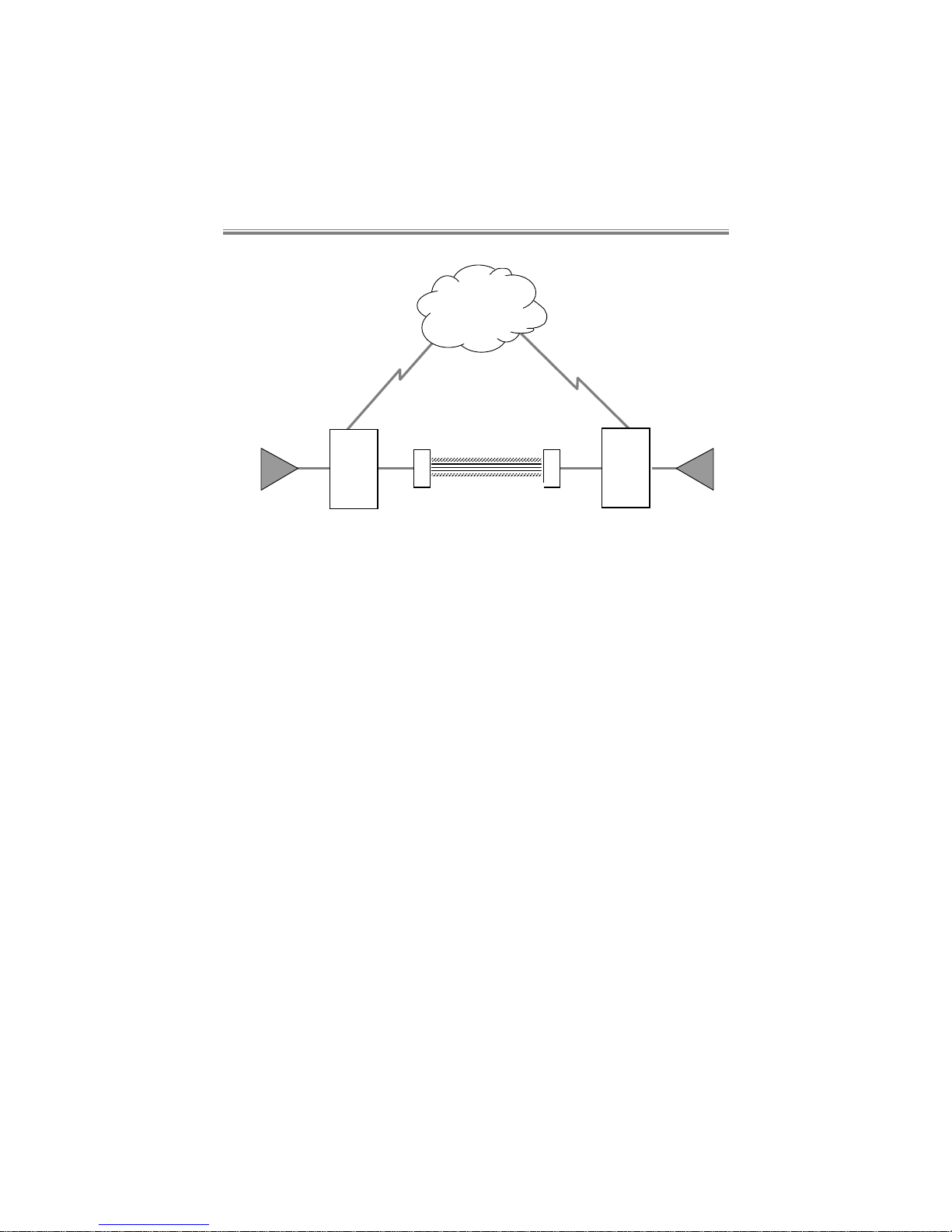
The SBU128 is designed to sit in the data path bet ween the PTO DLC
Network Termination Unit (NTU) and your user equipment, see Figure
1.1.
Page 8
SBU128
User Manual
80-10200000-011–2
ISDN
(Backup Circuit)
User
Equipment
User
Equipment
Digital Leased Circuit
N
T
U
N
T
U
(Main Circui t)
SBU128
SBU128
Figure 1.1 SBU128 sits in the data path
During norm al oper ati ng condi ti ons, user data passes ov er the DLC, with
the SBU128 remai ning transparent to t he system. If a fai lure occurs on
the DLC, this is detected by the SBU128. Af ter a user defined el apsed
tim e, the SBU128 dials a remot e SmartSW ITCH BACKUP unit v ia the
ISDN line. Upon verification of an acceptable connection the data is
then re-directed over this backup path.
The backup operation is user confi gured for eit her automatic or manual
initi ation. W hile the bac kup data circuit is in use the SBU128 m onitors
the fai led DLC line and upon detecti on of its recov ery clears t he ISDN
call, when data is returned to the DLC line (main leased circuit).
Note that the SmartSWITCH BACKUP product range was previously
known as the CyberBACKUP range, denoted by ‘CBU’ instead of ‘SBU’.
Page 9

This is the SBU128
80-10200000-01 1–3
1.2 Features
The main features include:
• Interference free operation of the DLC, with the SBU128 installed.
• Support for synchronous data rates of 600, 1k2, 2k4, 4k8, 9k6, 19k2,
38k4, 48k, 56k, 64k, 128kbit/s.
• Support for asynchronous data rates of 300, 600, 1k2, 2k4, 4k8,
9k6, 19k2, 38k4 bit/s.
• Asynchronous word lengths of 7, 8, 9, 10, 11 & 12 bits.
• Automatic fault detection on the DLC circuit.
• Fully automatic or manually initiated dialling and backup of the DLC.
• Local or remote control of the switch to the backup circuit.
• Fully automatic or manually initiated restoral to the main circuit.
• Automatic re-dial and alternate number dialling.
• Storage of 20 ISDN telephone numbers for the User port.
• 20 digit sub-address number.
• 20 digit Multiple Subscriber Number.
• User definable line failure detection modes.
• Remote Configuration and monitoring.
• Automatic Remote Alarm Reporting via ISDN ‘B’ channel.
• Structured operation and configuration menu system.
• Line integrity testing, both manual and automatic.
• ‘Alarm’ output port for event logging, printing.
• Security using Calling Line Identification.
• ‘Pass Through’ relays in the event of a power loss.
• Talkwire compatibility with other Cabletron SmartSWITCH BACKUP
products.
• Password protected command interface.
• Multiple Time Windows automatic back up operation.
• Remote backup spoofing to reduce the burden of central site call
costs.
• Local spoof of transmit data to prevent unwanted backup with host or
terminal failure.
Page 10

SBU128
User Manual
80-10200000-011–4
1.3 Product Overview
This user manual is arranged to take you through the basics of the
hardware, then to software set-up and on to the more special ised user
definable software facilities of your SBU128.
SBU128 software conf igurat ion i s generally not a compl ex operati on. In
many appli cati ons once you hav e correct ly conf igur ed the hardware and
installed your SBU128s, the default software configuration settings will
suffice to provide reliable backup operation.
In this section there is a brief ov erv iew of many of the m ore special ised,
software conf igur able, f eat ures of your SB U128. Eac h topi c i s dealt wit h
in detail later in this manual.
1.3.1 Network Security
Your SBU128 contai ns an integral security f acility, designed to protect it
from being accessed by unauthorised users via the ISDN.
If t he security opti on is enabled (ANSWER is set to CLID), the answering
SBU128 will only accept a call originating from an ISDN number
matching one of those stored in its file of telephone numbers.
1.3.2 Telephone Number Storage
The non vol ati l e m em ory will store up to 20 telephone numbers, allowing
you to select a backup telephone number for any particular circuit.
Alternative numbers can be dialled in the event of an unsuccessful call.
1.3.3 Circuit Failure
Your SBU128 can detect a circuit fai lure i f it det ects any of the f ollowing
conditions:
• No data is received from the DLC.
• No clock is detected on the link.
• The I/DSR signal from the DLC NTU goes to the OFF condition.
• The C/DTR signal from the User DTE equipment goes to the ON
condition.
User selectable time-outs can be independently set for all of the
detection facilities mentioned, except C/DTR from the DTE.
Page 11

This is the SBU128
80-10200000-01 1–5
1.3.4 Spoofing
There are two occurrences with automatic backup technology which
need to be provided for.
The fi rst is where a term inal or CPU stops transmi tti ng idl e data f rames.
In this instance the SBU128 would normally backup, which is
undesirable. Enabling the SBU128 Transmit Spoof causes a line
inversion to be sent once a second whenever no data is t r ansmitted from
the user DTE to the User port; this prevents data loss backup from
occurring.
The second is where a central sit e does not want to bear t he cost of all
backup calls. Enabling the Remote Backup Spoof ing causes transmit
data to the DLC to be clamped to a constant mark, thus causing the
remote SBU128 to detect dataloss, and then backup.
1.3.5 Talkwire
Talkwire is the facility which enables remote control and conf igurati on of
an SBU128 over the ISDN network when data is being routed ov er the
DLC.
As this feature allows you access to all SBU128s connect ed to the I SDN
(providing you have the correct telephone number), the SBU128
supports the Network provided Calling Line Identification facility for
enhanced security.
1.3.6 Polling
In a large network of SBU128s, all units can be interconnected and
controlled using a single terminal.
A “poll” number can be set for each unit within the group, allowing
indiv idual SBU128s to be accessed from the terminal by using the poll
numbering system.
Page 12

SBU128
User Manual
80-10200000-011–6
1.3.7 Alarms
Various alarm condit ions are av ail able t hat alert the user to the SBU128
alarm status. You can also define which of these EVENTs you want to
be output as an ALERT. T he ALERT message is defined as being an
alarm that is passed across a network of sev eral Cabl etr on backup uni ts.
An EVENT message occurs locally, and is seen only when the unit is
actively polled.
For example, incoming calls and DLC failure can be programmed to
cause ALERTs, Talkwire Active/Inactive and Ringing are only events.
An ALERT m essage can also be programmed to occur when password
access is denied.
Page 13

The Hardware
80-10200000-01 2–1
2 The Hardware
2.1 Introduction
All SBU128 configuration options are software controlled, and settings
can easily be altered after the unit is installed in the system.
However the physical interface characteristics of the USER and LINK
ports are defi ned at manufac ture by using separate pcb m odules which
are not changeable except at the premises of your equipment supplier
and maintainer. They must only be changed by your supplier or
installation engineer.
WARNING. Access to the intern al workings of your SBU128 is
strictly denied to all users, and may only be performed by
suitably qualified personnel. Any attempt to remove the ou ter
casing of your product will invalidate its approval.
Zone dangereuse! reservée au personnel autorisé. Ne pas
ouvrir. Tensions dangereuses.
Gefäh! Bereich. Nur für fachpersonal. Nicht öffnen
berührungsgefahr!
Pericole! Solo personale addestrato. Non aprire. Tensioni
pericolase all ‘interno.
Area peligrosa solo personal mantenimiento. No abrir.
Tension. Peligrosa.
Page 14

SBU128
User Manual
80-10200000-012–2
Area perigosa somente pessoal técnico treinado. Não abra.
Voltagens perigosas no interior.
Farligt omräde endast för utbildad personal. Öppna ej. Farlig
spanning inuti.
Farligt omräde. Kun adgang for teknisk uddannet personale.
Farlig spænding indeni. Luk ikke op.
Vaarallinen alue vain koulutetulle huoltohenkilöstölle.
Vaarallinen jännite. Alã avaa.
Fare - Må ikke åpnes. Farlige spenninger innenfor.
Gevaarlijk. Toogang alleen voor onderhoudspersoneel. Niet
openen. Gevaarlijke voltages.
2.2 DLC Interface Characteristics
X21 and X21bis Digital Leased Circuit types include V11 and V35 as
electrical interface options.
Your SBU128 has been designed for compatibility with V35 and X21
interfaces, through choice of pcb interface module at the time of
ordering.
A one to one cable is required on both the User and Link sides of the
SBU128. Cable speci fi cati ons are detai led i n secti on 10 and cables are
available from your SBU128 supplier.
Page 15

The Hardware
80-10200000-01 2–3
2.3 Interface Pin Assignments
2.3.1 User and Link
Pin assignments of the USER and LINK connectors will vary with the
interface module type.
The USER ports are configured as physical DCEs and the LINK ports are
configured as physical DTEs. Their pin assignments are:
V35 operation
Pin Circuit Signal
A 101 Protective Ground
B 102 Signal Ground/Common Return
C 105 Request to Send
D 106 Clear to Send
E 107 Data Set Ready
F 109 Data Channel Received Line Signal Detector
H 108 Data Terminal Ready
J 125 Calling Indicator
K - Unused
L 141 Local Loopback
M - Unused
N 140 Loopback/Maintenance Test
P 103(A) Transmitted Data A
R 104(A) Received Data A
S 103(B) Transmitted Data B
T 104(B) Received Data B
U - Unused
V 115(A) Receiver Signal Element Timing A
W - Unused
X 115(B) Receiver Signal Element Timing B
Y 114(A) Transmitter Signal Element Timing A
Z - Unused
AA 114(B) Transmitter Signal Element Timing B
BB - HH Unused
JJ Unused
KK Unused
LL Unused
MM - Unused
NN 142 Test Indicator
Page 16

SBU128
User Manual
80-10200000-012–4
See section 2.4.1 f or details of Pin 1 connection to Protectiv e Ground,
factory default setting assumes no links fitted.
X21 operation
Pin Circuit Signal
1 SHLD Protective Ground
2 T(A) Transmit
3 C(A) Control
4 R(A) Receive
5 I(A) Indication
6 S(A) Signal Element Timing
7 - Unused
8 G Signal Ground or Common Return
9 T(B) Transmit
10 C(B) Control
11 R(B) Receive
12 I(B) Indication
13 S(B) Signal Element Timing
14 - Unused
15 - Unused
See section 2.4.2 f or details of Pin 1 connection to Protectiv e Ground,
factory default setting assumes no links fitted.
2.3.2 Command Port
Pin assignments on the 25-way connector are:
Pin no. Circuit Circuit name Source
1 GND Protective Ground
2 103 Transmit Data DTE
3 104 Receive Data DCE
4 105 Request To Send DTE
5 106 Clear To Send DCE
6 107 Data Set Ready DCE
7 102 Signal Ground
8 109 Data Carrier Detect DCE
9 -19 Not used
20 108/2 Data Terminal Ready DTE
21-25 Not used
Page 17

The Hardware
80-10200000-01 2–5
2.4 X21 and V35 Interface Links
JP 1 connects Signal Ground (SG) to Protective Ground (PG) for the
SBU128.
All links are found on the interface pcb.
2.4.1 X21 USER/LINK Pin 1 Definition
Pin 1 on the 15-way X21 USER and LINK connect ors can be connected
to Protective Ground (PG) using pcb links.
Shorting Link Pin definition
JP1 SG - PG
JP7 User port pin 1 to PG
JP8 Link port pin 1 to PG
2.4.2 V35 USER/LINK Pin 1 Definition
Pin ‘A’ on the V35 USER and LINK connectors can be connected to
Protective Ground using pcb links.
Shorting Link Pin definition
JP1 SG - PG
JP2 User port pin 1 to PG
JP3 Link port pin 1 to PG
2.4.3 X21 Receiver Terminations
The fol lowing li nks when fitted, apply a 120 ohm t erminat ion to the V11
receivers as follows:-
Shorting Link Interface Circuit
JP2 User T
JP3 User C
JP4 Link R
JP5 Link I
JP6 Link S
2.4.4 V35 Receiver Terminations
Receiv er term ination resi stors are fit ted on these interf aces, and cannot
be deselected.
Page 18

SBU128
User Manual
80-10200000-012–6
2.4.5 ISDN
The following links when fitted to the ISDN pcb, apply a 100 ohm
termination to the ISDN transmit and receive pairs as follows:-
Shorting Link Pair
JP1 Receive
JP2 Transmit
These links m ay need to be inserted when a longer S-bus line l ength i s
used.
2.5 Command Terminal Access
Software conf iguration and contr ol of your SBU128 is achi eved vi a the
Command port on the rear panel, using a loc al term inal, m odem or PC.
The port is configured as a physical DCE, the terminal standard is
VT100, with data transfer at 9600 bit/ s, no parity , 8 data bi ts, 1 start and
1 or 2 stop bits. This data rate can be altered by software command. No
terminal emulation is used.
There is no hardware configuration to the Command port.
2.6 Non Volatile Options
These options are “non-v olati le” because they are not default ed when a
factory default is performed. However the first “A” option in each submenu is the pref erred setti ng that is natural ly set (by v irt ue of all “1”s in
the RAM locations) when the unit is built , unless specif ic ally changed for
the country of destination.
2.6.1 Product and Network Variants
Diff erent operational m odes can be selected with the Product Variants
menu. Different Network Variants can be selected allowing several
different count ri es and product variant s to use the same soft ware hel d in
FLASH memory.
Both these v ariant s can be changed v ia t he Non Volati le Opti ons m enu,
obtainable by typing the letter ‘K’ at the top level menu. The correct
variants are set for the destination country and application before
shipping.
Page 19

The Hardware
80-10200000-01 2–7
All Non Volatile Options are set during manufacture and must
not be changed, except by a competent engineer.
Network Variant 0 i s for most European networks, m ost other countr ies
with Euro-ISDN are likely to require Network Variant 0. Network
Variant 2 is the same as Variant 0 except that it does not have single
octet information elements present in the call setup message.
Please contact your Technical Support for further information.
NOTE: Network Variants 1 onw ards must not b e set in the UK,
otherwise the Approval of this product will be invalidated.
Changes to this setting must only be made by a competent
engineer.
2.6.2 S-Bus Power Detection
S-Bus Power Detection must be enabled for al l UK and European ISDN
applications, where ‘Power Source 1’ detection is a regulatory
requirem ent. Where ‘Power Source 1’ i s not provided (i . e. on som e PBX
internal ISDN extensions), S-Bus Power Detection should be disabled,
otherwise ISDN calls will not be possible.
Presence of ‘Power Source 1’ i s where 40V DC power is appl ied by the
network between the transmit and recei v e ‘S’ bus pairs. Enabl ing power
source detection m eans that l ine power m ust be present bef or e cal ls can
be made or received.
All Non Volatile Options will be set during manufacture and
must not be changed, except by a competent engineer.
It is possible that a designated “country” v ariant could be used i n another
country if approvals in that country permit it.
If an SBU128 i s upgraded with later software, pl ease contact your local
Technical Support organisation for further information.
Page 20
Front and Rear Panel Descriptions
80-10200000-01 3–1
3 Front and Rear Panel Descriptions
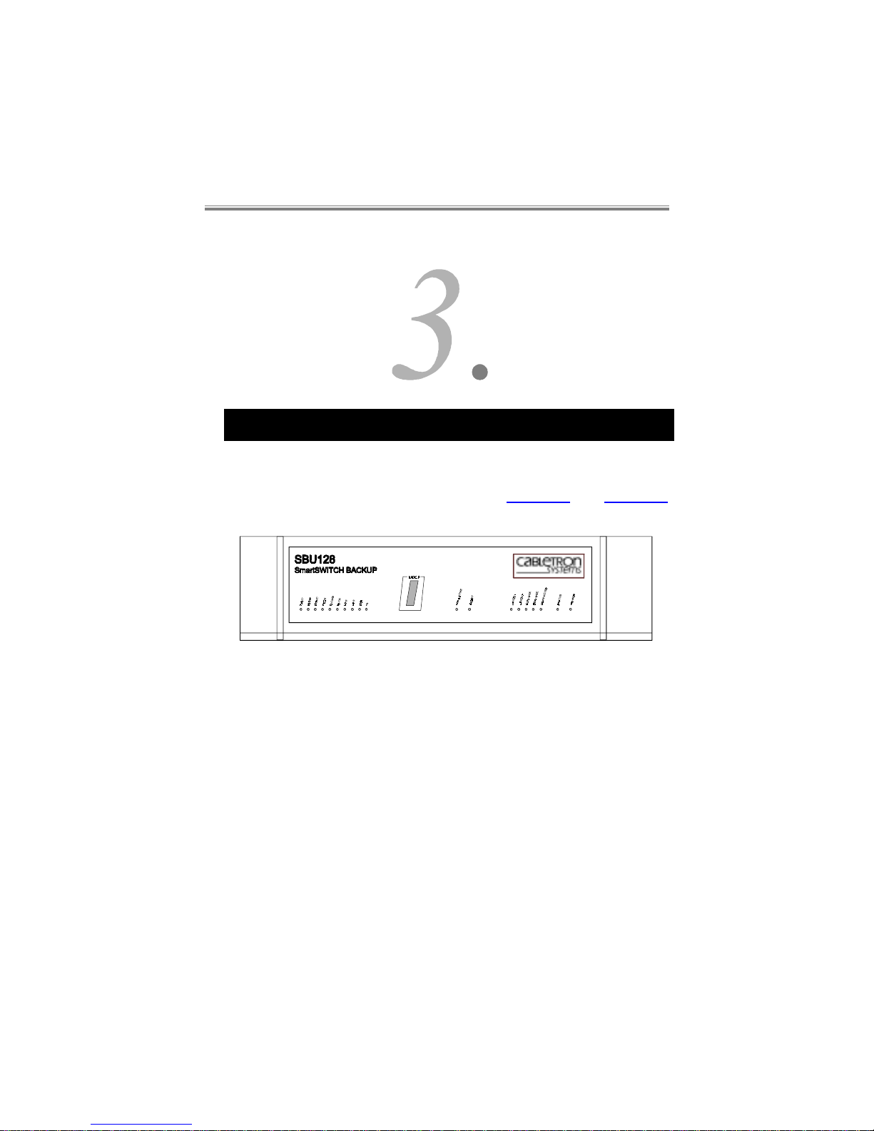
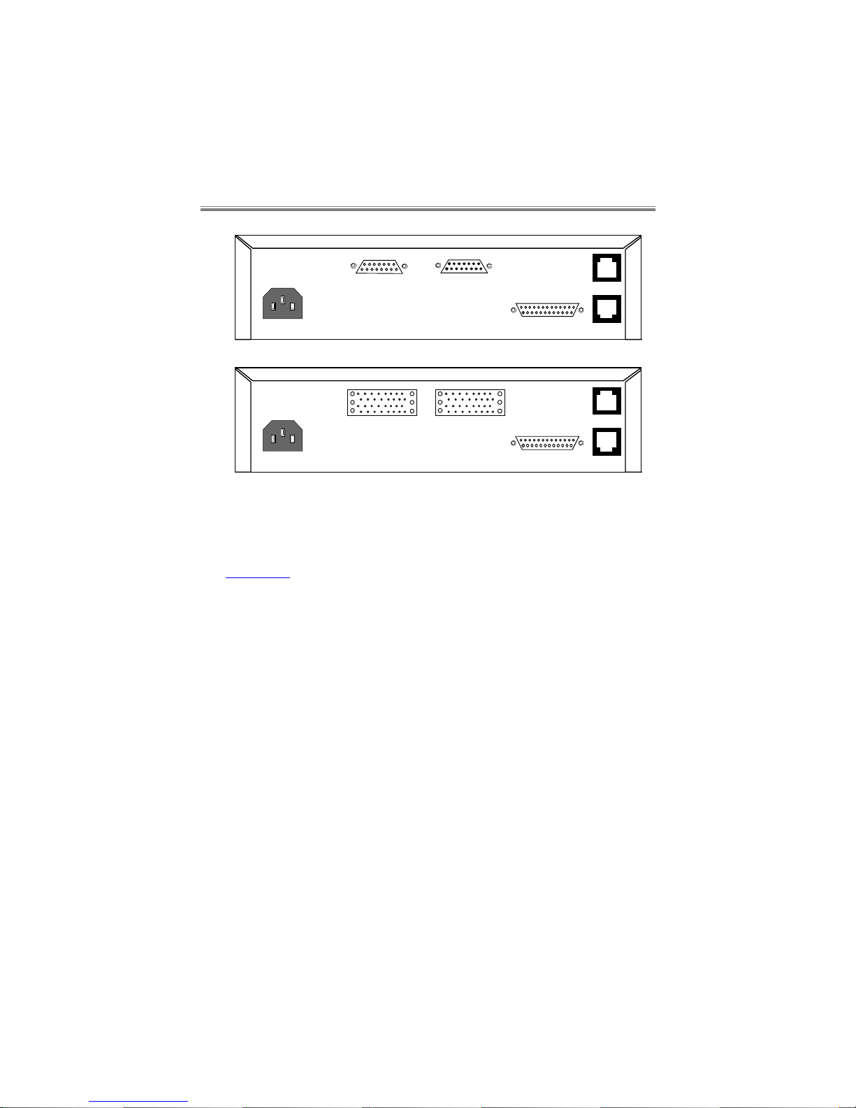
The SBU128 is a standalone uni t designed to si t on a desktop, or a shelf
in a standard communications cabinet. All physical connections are
made by connectors on the rear panel, see Figure 3.1 and Figure
3.2
below:-
Figure 3.1 SBU128 Front panel
Page 21
SBU128
User Manual
80-10200000-013–2
ISDN BRI
Command
(X.21)
LinkUser
User
(V.35)
Link
10 BASE-T
ISDN BRI
Command
10 BASE-T
Figure 3.2 SBU128 Rear panels
3.1 Front Panel Description
Figure 3.1 shows the front panel of your SBU128, which has the
following:-
•
signal LEDs for each of the User interface circuits
•
a non-latching, push-button switch for manual backup operation.
•
Talkwire and ALERT LEDs
•
status LEDs for the ISDN channels
•
a User port “Connected” LED
•
a unit status and power LEDs.
Page 22

Front and Rear Panel Descriptions
80-10200000-01 3–3
3.1.1 USER Indicators
The indic ators for USER 1 ref lect the signal activ ity on the X21 or V35
User connectors, depending which interface pcb is fitted.
TxD/T Lights to indicate the state of Transmit Data as being ON
(SPACE).
RxD/R Lights to indicate the state of Receive Data as being ON
(SPACE).
DTR/C Lights to indicate the state of Data Terminal Ready as
being ON (SPACE). Wi th the X21 interface this indicates
the state of the Control circuit.
DCD/I Lights to indicate the state of Data Carrier Detect as being
ON (SPACE). With the X21 interface this indicates the
state of the Indicate circuit.
TxCLK/S Lights to indicate the state of Transmit Clock as being ON
(SPACE). Wi th the X21 interface this indicates the state of
the Signal Element Timing circuit.
RxCLK Lights to indicate the state of Receiv e Clock as being ON
(SPACE). With the X21 interface this indicator is not used.
RTS Lights to indicate the state of Request To Send as being
ON (SPACE). Wi th the X21 interface this indicator is not
used.
CTS Lights to i ndicate the state of Clear To Send as being ON
(SPACE). With the X21 interface this indicator is not used.
DSR Lights to indic ate the state of Data S et Ready as being ON
(SPACE). With the X21 interface this indicator is not used.
RI Lights to indicate the state of Ring Indicate as being ON
(SPACE). With the X21 interface this indicator is not used.
Page 23

SBU128
User Manual
80-10200000-013–4
3.1.2 BACKUP Button, Factory Default
A non-latching switch is prov i ded f or m anual bac kup and restoral . When
pressed the SBU128 will attempt a backup call using the stored ISDN
number(s). I f pressed when a backup call i s i n pr ogr ess, the S B U128 will
restore the user onto the leased circuit, and release the ISDN call.
It is not adv isable t o use the backup button when the SBU128 i s set for
automatic backup or restoral as this causes operational conflict.
The backup button i s also used to f act ory default ( retur ning c onf i gurati on
settings to default values) the SBU128 on power up, by holding it
depressed for about 2 seconds until the Lay er 1 LED illuminates. At this
point it must be released to perfor m the default . If f or any reason t he
button is held in for more than 10 seconds, other LEDs will light
indicat ing that the unit has entered other servi ce states. The unit must
be power cycled again to exit this mode, and correctly factory defaulted.
3.1.3 Talkwire and ALERT Indicators
The Talkwire LED lights when a Talkwire session is active, and the
ALERT LED lights when an ALERT is being transmitted from the
Command Port
Page 24

Front and Rear Panel Descriptions
80-10200000-01 3–5
3.1.4 ISDN Indicators
These indicate the state of channels 1 and 2 on the ISDN and are:-
Indicator Channel state
LAYER 1 Alight when the ISDN at Layer 1 (physical layer) is
activ e. When not ali ght when dialling indi cates lack of
connection to the ISDN.
LAYER 2 Alight when the ISDN at Layer 2 (link layer, LAPD) is
activ e. This must be ali ght f or call s to be made. If not
alight check firstly the ISDN connection, then try
diall ing agai n. If still not alight check with your network
provider.
B1 IN USE Light s to indi cate B channel 1 on the ISDN i s in use (i s
carrying a call).
B2 IN USE Light s to indi cate B channel 2 on the ISDN i s in use (i s
carrying a call).
CONNECTED Lights to i ndicate t hat the User port is connected t o the
ISDN in backup, and data is passing ov er the ISDN B
channel.
3.1.5 Status Indicator
When powering up, the STATUS LED is on solid for several seconds
while the unit l oads its operat ional sof tware. When loaded, t he STA TUS
LED will flash slowly indicating unit operational status.
3.1.6 Power Indicator
This indi cates the presence of i nternal DC power. Thi s indicator should
always be lit when mains power is connected.
Note that if the SBU128 is not powered up, the internal pass through
relays will connect the USER port to the LINK port. This will allow
normal oper ati on of t he user’s equipm ent, alt hough the I SDN back up wil l
not function.
Page 25

SBU128
User Manual
80-10200000-013–6
3.2 Rear Panel Description
3.2.1 Command Port
A 25 pin female D-Type V24/V28 interface connector provides
connection to your local terminal, PC, or modem for software
configuration control.
The port is confi gured as a physical DCE oper ating at a fi xed rat e (9600
bit/s, no parity, 8 data bits, 1 start and 1 or 2 stop bi ts. P ort dat a rat e can
be altered by software command.
3.2.2 USER and LINK Ports
The SBU128 has been designed so as to permit the user to insert the
unit between the user equipment and the DLC. To maintain the
simpli city of this system, the USER port is defined as a physical DCE
and the LINK port as a physical DTE.
Wi th the unit switched off , or in t he event of a power fai lure, the USER
port is connected directl y to the LINK port via rel ay cont act s. When your
SBU128 is powered on, the relays are energised, causing the direct
connection to be broken, whilst the signals are routed through the
interface receivers and transmitters of your SBU128.
All operat ing parameters, such as speed, data, parity etc., are software
defined. Settings may be altered using a terminal connected to the
COMMAND port.
3.2.2.1 USER and LINK Pin Assignments
In section 2 of this manual is detailed the various electrical
characteristics supported by your SBU128.
Please see section 10 for details of the adaptor cables required for
connecting to these ports.
3.2.3 ISDN
A fixed lead and plug is supplied for connection to your ISDN outlet,
providing two 64kbit/s channels.
See Figure 3.3 below for details of the RJ45 pin numbering.
Page 26

Front and Rear Panel Descriptions
80-10200000-01 3–7
Cable Entry
point
Pin 8
Latch, at rear
Pin 1
Figure 3.3 RJ45 Connector showing pin connections
The pin assignment on the RJ45 is with pin 1 on the lef t, with the plug
pins facing you and the cable entry pointing downwards.
3.2.3.1 Basic Rate S (Europe) Interface
When the SBU128 is supplied in countries other than the USA, the
following pins are used in the RJ45 connector:
RJ45 Wire Colour Signal
pin 3 White Transmit
pin 4 Green Receive
pin 5 Blue Receive
pin 6 Red Transmit
Page 27

SBU128
User Manual
80-10200000-013–8
3.3 Mains Input and Wiring
On the rear of t he unit there is one IE C mains socket for connection to
an independent m ains supply. The pri mary earth connection is made via
this socket.
WARNING - this appliance must be earthed.
VORSICHT - Nur eine vorschriftsmäßig geerdete Steckdose
anschließen.
A single mains cable is supplied with the SBU128, 2 metres in length
with an appropriate approved plug for the country concerned. This
should be connected to a suit able mai ns supply. The m ains plug is the
primar y disconnect dev ice for the uni t. Ensure that the uni t is i nstalled
near to a socket outlet and that the outlet is easily accessible.
N.B. The use of adaptors is not recommended and may invalidate
approval of the product.
The wires in the supply cord are coloured in accordance with the
following code:-
Green and Yellow Earth
Blue Neutral
Brown Live
As these colours may not correspond with the termi nations in the plug
being used, it should be connected as follows:-
The green and yellow wire must be connected to the terminal marked
with the let ter E , or wit h the ear th sym bol , or c olour ed green, or col oured
green and yellow.
The blue wire must be connected t o the termi nal marked with t he letter
N, or coloured black, or coloured blue.
The brown wire must be connect ed to t he term i nal m arked wit h the l ett er
L, or coloured red, or coloured brown.
All dat a communicati ons links to the unit should be i n accordance with
the cable specifications given in this manual.
WARNING:
Page 28

Front and Rear Panel Descriptions
80-10200000-01 3–9
1. Only connect apparatus complying with the requirements of
SELV in accordance with clause 2-3 of E N 60 950 to t he ports
on the rear panel of your unit marked “User, Link, 10 Base- T
and Command”.
An die Anschluesse “User, Link, 10BaseT, und Command”
auf der Rueckseite des Geraetes duerfen nur Komponenten,
die fuer SELV bestimmt sind und der Vorschrift EN 60950/2-3
genuegen, angeschlossen werden.
2. Only connect apparatus complying with the requirements of
TNV 1 in accordance with clause 6 of EN 60 950 t o the port
on the rear panel of your unit marked “ISDN BRI”.
An den Anschluess “ISDN BRI” auf der Rueckseite des
Geraetes duerfen nur Komponenten, die fuer TNV-1
bestimmt sind und der Vorschrift EN 60950/6 genuegen,
angeschlossen werden.
3.4 Supply Ratings
WARNING:
1. The unit should be professionally installed by a competent
engineer. There are no operator serviceable parts inside
the unit and it should only be opened by a qualified service
engineer. The mains supply should be disconnected before
accessing the interior.
Gefäh! Bereich. Nur für fachpersonal. Nicht öffnen
berührungsgefahr!
The unit can be connected to supplies of the following voltage ranges:a)100 to 120VAC Nominal (Tolerance Range of 90 to 132VAC)
b)220 to 240VAC Nominal (Tolerance Range of 198 to 254VAC)
Supply frequencies, in all cases, can be in the range 48Hz to 62Hz.
Page 29

SBU128
User Manual
80-10200000-013–10
The maxi mum power consumption of the power supply uni t is 30 watts.
The current requirement for each of the voltage ranges is:-
a) 0.5A max.
b) 0.25A max.
Page 30

Configuration Commands
80-10200000-01 4–1
4 Configuration Commands
4.1 Introduction
There are three ways you can gain access to, and alter the software
configuration options on your SBU128;
• by direct VT100 terminal access (local connection t o the COMMAND
port of your SBU128)
• by Talkwire link (from a remote SmartSW IT CH BACKUP unit placing
a call to the SBU128, over the ISDN)
• by remote Telnet session over the LAN.
In this section we only refer to local terminal access, remote
configuration is covered in more detail later in this manual.
Terminal connection requi res that the SBU128 CO MMAND port i s set to
comm unicate at 9600 bit /s, no parity, 8 dat a bits, 1 start bi t and 1 stop
bit. Although the data rate of t he port may subsequently be alter ed by
software command.
The cable required between your VT 100 term i nal and SBU128 shoul d be
a ‘straight through’ V24 cable with D type connectors as described in
section 10.
4.2 Menu Description
The comm and structur e for t he SBU128 is a m enu driv en system with a
hierarchical type of structure, similar to that used by other
Page 31

SBU128
User Manual
80-10200000-014–2
SmartS WITCH B ACKUP products. See section 11 f or diagrams of t he
menu structure.
The foll owing comm ands have a special m eaning and are ex ecuted wit h
single keystrokes:-
1
Selects port 1.
M
Selects the Management port.
R
Selects the Remote Alarm port.
S
Displays the status information of the SBU128.
T
Returns to the top level menu.
X
Goes back (up) one level in the menu system.
4.3 Top Level Menu
Operation Menu See section 4.4
Configuration Menu See section 4.5
Logout Logs the user out of password entry.
Non Volatile Options See section 4.10.
Page 32

Configuration Commands
80-10200000-01 4–3
4.4 Operation menu
A) DIAL
Dials the first number in the
number store.
B) DIAL nnn
Prompts you for a number and
then dials it.
C) DIAL Nn
Prompts you for an address in the
number store and then dials the
number contained in it.
D) LIST ALL
NUMBERS
Lists all the numbers in the
number store.
E) ANSWER
Answers the incoming call.
F) HANGUP
Clears the call.
G) TALKWIRE
Provides Talkwire commands.
* ) CONNECT
Connects the user port
to the ISDN call.
B) LOCAL
Shows the command
menu of the local
device.
C) REMOTE
Shows the command
menu of the remote
device.
D) HANGUP
Clears the call.
H) LOCAL
LOOPBACK
A) ON
Data received by the SBU128
from the user interface RxD is
looped back to the user
Interface TxD.
B) OFF (F)
Terminates the loop.
Page 33

SBU128
User Manual
80-10200000-014–4
I) REMOTE
LOOPBACK
A) ON
Data received by the SBU128
from the ISDN is looped back
to the ISDN. A Talkwire
management call needs to be
in progress to control this loop.
B) OFF (F)
Terminates the loop.
J) DISPLAY ALERT
LOG
Displays the last 100
ALERTs generated.
4.5 Configuration menu
The
(F)
in the text represents the factory default setting.
Factory defaulting: The backup button is also used to factory default
(returning conf igurat ion settings to def aul t v alues) t he SBU128 on power
up, by holding it depressed for about 2 seconds until the Layer 1 LED
illuminates. At this point it must be released to perform the default. If
for any reason the button is held in for more than 10 seconds, other
LEDs will light indicating that the unit has entered other service states.
The unit must be power cycled again to exit this mode, and correctly
factory defaulted.
Any menu that is “starred” is unavailable on the terminal
screen. It is there just to provide menu similarity with other
SmartSWITCH BACKUP products.
Page 34

Configuration Commands
80-10200000-01 4–5
4.5.1 System Menu
A) SYSTEM
MENU
A) CHANGE
PASSWORD
Allows the user to change the
SBU128 password.
B) POLL
NUMBER
This command is only available
for standalone units.
C) SET TIME
Enable the user to set
theSBU128 real time clock.
D) SET DATE
Enables the user to set the date
of the real time clock.
E) PASSWORD
TIMER
A password entry time of 0 or
10-999 seconds can be entered.
(Default is 0)
4.5.2 Command Port Menu
This sub-menu configures the speed of the command port.
A) SPEED A) 1k2
B) 2k4
C) 4k8
D) 9k6 (F)
E) 19k2
F) 38k4
G) 57K6
H) 115K2
B) ECHO A) ENABLED (F)
B) DISABLED
Page 35

SBU128
User Manual
80-10200000-014–6
C) CONSOLE A) NORMAL (F)
Used when connected
directed to the management
console.
B) POLLED
Used when the Command
Port is connected to a
SBUGPS.
D) FLOW
CONTROL
A) RTS/CTS
RTS/CTS flow control is
effective.
B) XON/XOFF
DC1/DC3 inband flow control
is effective.
C) DISABLED (F)
No flow control is used on the
Command Port.
E) ALERTS A) SHORT
FORMAT (F)
No time and date provided
with ALERTs.
B) LONG
FORMAT
Time and date stamp
provided with all ALERTs.
C) DISABLED
No ALERTs presented.
F) EVENTS A) ENABLED (F)
Events are presented
B) DISABLED
Events are not presented
Page 36

Configuration Commands
80-10200000-01 4–7
4.5.3 Alarm Port Menu
*) SPEED
*) ECHO
No selection is possible.
C) MODE A) REMOTE A) LOW PRIORITY
(F)
If all ‘B’ channels are
busy, the alarm call is
made when a ‘B’
channel is free.
B) HIGH PRIORITY
Alarm call is made
before the ‘B’ channel
is used for backing up
the User port.
D) FLOW
CONTROL
A) RTS/CTS (F)
RTS/CTS flow control is
effective.
B) XON/XOFF
DC1/DC3 inband flow control
is effective.
C) DISABLED
No flow control is used on the
Command Port.
E) ALERTS A) SHORT
FORMAT
No time and date provided
with ALERTs.
B) LONG
FORMAT
Time and date stamp
provided with all ALERTs.
C) DISABLED (F)
No ALERTs presented.
F) QUEUE
LENGTH
This sets the length of the
queue required before an
alarm call is made.
G) FLUSH TIMER
This sets the time at which
stored ALERTs are deleted
H) CALL HOLD
TIME
This sets how long that the
ISDN call is maintained, after
transmitting the outstanding
ALERTS held in memory.
Page 37

SBU128
User Manual
80-10200000-014–8
4.5.4 Alarms menu
A) ALERT PASSWORD
A) ENABLED (F)
Sends an alert indicating when
whenever three successive incorrect
attempts have been made to log in
to the menu system:-
ALERT Unauthorised access
attempt
B) DISABLED
This ALERT is disabled.
B) ALERT CHANNEL STATUS
A) ENABLED (F)
Sends an alert indicating:-
ALERT Channel status 1
Port disconnected, no ‘B’ channels
in use.
ALERT Channel status 2
Port disconnected, one or more ‘B’
channels in use.
E.g
. a Talkwire
call.
ALERT Channel status 3
Port connected, one or more ‘B’
Channels in use.
B) DISABLED
This ALERT is disabled.
Page 38

Configuration Commands
80-10200000-01 4–9
C) ALERT DIAL
A) ENABLED (F)
Sends an alert indicating you are
dialling a number. The alert
message is:
ALERT Dialling nn..n or
ALERT Dialling nn..n/
mm..m
Where nn..n is the dial number and
mm..m is the sub-address.
B) DISABLED
This ALERT is disabled.
D) ALERT INCOMING CALL
A) ENABLED (F)
Sends an alert indicating an
incoming call. The alert message
is:
ALERT Incoming call or
ALERT Incoming call
(nn...n)
Where nn...n is the source of the
call.
B) DISABLED
This ALERT is disabled.
E) ALERT ISDN VERIFY
A) ENABLED (F)
Sends an ALERT for either pass or
fail of the daily ISDNTEST.
B) DISABLED
This ALERT is disabled.
F) ALERT LINE ACTIVITY
A) ENABLED (F)
Sends ALERTs for Line Active or
Inactive status.
B) DISABLED
This ALERT is disabled.
Page 39

SBU128
User Manual
80-10200000-014–10
G) ALERT BACKUP
A) ENABLED (F)
Sends Backup or Restore ALERTs.
B) DISABLED
This ALERT is disabled.
H) ALERT LAPD ACTIVITY
A) ENABLED (F)
Sends an ALERT indicating whether
ISDN LAPD (Link layer) is active or
inactive. It must be active for the
UNIT to be able to make or receive
calls. The ALERT message is:
ALERT LAPD active
or
ALERT LAPD inactive
B) DISABLED
This ALERT is disabled.
I) ALERT INSUFFICIENT B-CHANNELS
A) ENABLED (F)
Sends an alert indicating that a call
attempt failed due to an insufficient
number of ‘B’ Channels being
available. The alert message is:
ALERT Insufficient BChannels.
B) DISABLED
This ALERT is disabled.
Page 40

Configuration Commands
80-10200000-01 4–11
J) ALERT B-CHANNEL USAGE
A) ENABLED (F)
Sends an ALERT indicating how
many ‘B’ channel s are in use. The
ALERT message is:
ALERT B-Channel usage x,y
Wher e x and y are num erals in the
range 0 - 2 and :-
x is the number of channels in use
and y is the number of channels
remaining available.
x + y = 2.
B) DISABLED
This ALERT is disabled.
K) ALERT SYSTEM
A) ENABLED (F)
Sends an alert indicating that a call
attempt failed due to an insufficient
number of ‘B’-Channels being
available. The alert message is:
ALERT Insufficient BChannels
B) DISABLED
Sends an ALERT indicating system
states:
ALERT System 0 Bank A
When the unit has booted from
Bank A Flash.
ALERT System 0 Bank B
When the unit has booted from
Bank B Flash.
ALERT System 1
When the NVRAM has been
defaulted, due to the NVRAM being
corrupted, reset, or a request for it
to be restored.
Page 41

SBU128
User Manual
80-10200000-014–12
4.5.5 User Port menu
EDIT STORE
allows the user to edit the confi gur ation stores of the ports.
Selecti on of a port l eads you to a f urt her selec ti on of Menus, see secti on
4.5.6.
Many sub-menus are not avail able (because they are not needed) for the
Remote Management and Remote Alarm ports.
A) EDIT
STORE
A) USER PORT
Current store for the User port
held in non-volatile memory.
B) REMOTE
ALARM PORT
Current store for the Remote
Alarm port held in non-volatile
memory.
C) REMOTE
MANAGEMENT
PORT
Current store for Remote
Management port held in nonvolatile memory.
D) STORE 1
Factory default configuration
from this store is copied to the
User port when the unit is
factory defaulted.
E) STORE 2
Spare store.
F) DISPLAY INTERFACE STORES
G) DISPLAY BACKUP STORES
4.5.6 Edit Store Menus
A) INTERFACE
See section 4.5.6.1
B) CALL CONTROL
See section 4.5.6.2
C) LEASED CIRCUIT FAILURES
See section 4.5.6.3
D) BACKUP
See section 4.5.6.4
E) RESTORE
See section 4.5.6.5
F) TIME WINDOWS
See section 4.5.6.6
G) ISDNTEST
See section 4.5.6.7
Page 42

Configuration Commands
80-10200000-01 4–13
4.5.6.1 Interface menu
Interface signals DSR, CTS, RTS and LAL are only av ailable wit h the
V.35 interface.
A) COMMAND
MODE
Selects the type of call control for the user port.
A) DTR
ORIGINATE
DTR call control as
originating calls when C/DTR
goes ON.
B) DTR ANSWER
DTR call control as
answering calls with C/DTR
ON. This setting overrides
the ANSWER MAN/AUTO
setting.
C) BACKUP (F)
Automatic backup and
restoral control.
B) DATA
Selects data type for the user port.
A) SYNC (F)
Synchronous 8 bit operation.
B) ASYNC
Asynchronous operation.
A) DATA BITS
The number of data bits in
each asynchronous
character.
A) 5 BIT
B) 6 BIT
C) 7 BIT
D) 8 BIT (F)
Page 43

SBU128
User Manual
80-10200000-014–14
B) PARITY
Selections for the parity
checking of each character.
A) OFF (F)
B) EVEN
C) ODD
D) MARK
E) SPACE
C) STOP BITS
The number of stop bits in
each character.
A) 1 (F)
B) 2
C) SPEED
Selects desired speed for the user port.
A) 300
Asynchronous operation only
B) 600
C) 1K2
D) 2K4
E) 4K8
F) 9K6
G) 19K2
H) 38K4
I) 48K
Synchronous only.
J) 56K
Synchronous only.
K) 64K (F)
Synchronous only.
L) SWITCHED 56K
Synchronous only. This
must be set for calls to USA
where 7 bit structured 56k
networks are used.
M) 128K
Synchronous only
Page 44

Configuration Commands
80-10200000-01 4–15
D) USER RATE
NOTIFICATION
A) DISABLED (F)
User rate information not
sent.
B) ENABLED
Enables the transmission of
the user rate speed
information in the ISDN call
setup.
E) C/DTR
Selects what the DTR or C input should be.
A) NORMAL (F)
Input comes from the DTE.
B) FORCED ON
Input is forced on in
SBU128.
C) FORCED OFF
Input is forced off in
SBU128.
F) I/DCD
Selects what the DCD or I output should be.
A) NORMAL (F)
Output comes from the
SBU128.
B) FORCED ON
Output is forced on from the
SBU128.
C) FORCED OFF
Output is forced off from the
SBU128.
G) DSR
Selects the required DSR output.
A) NORMAL (F)
Output comes from the
SBU128.
B) FORCED ON
Output is forced on from the
SBU128.
C) FORCED OFF
Output is forced off from the
SBU128.
Page 45

SBU128
User Manual
80-10200000-014–16
H) CTS
Selects the required CTS output.
A) NORMAL (F)
Output comes from the
SBU128.
B) FORCED ON
Output is forced on from the
SBU128.
C) FORCED OFF
Output is forced off from the
SBU128.
D) FOLLOWS DCD
Output follows the state of
the DCD output.
I) RTS
Selects the required RTS input.
A) NORMAL (F)
Input comes from the DTE.
B) FORCED ON
Input is forced on in
SBU128.
C) FORCED OFF
Input is forced off in
SBU128.
J) LAL
CONTROL
Selects if the loop pin on the SBU128 is enabled
(pin L on The V.35 interface)
A) DISABLED (F)
Disables the loop pin input.
B) ENABLED
Enables the loop pin input.
Page 46

Configuration Commands
80-10200000-01 4–17
4.5.6.2 Call control menu
A) ANSWER
Determines how the SBU128 responds to an incoming
call.
A) AUTO (F)
Answers an incoming call
automatically.
B) CLID
Answers the call only if the
originating number matches
a number in the CLID store.
Otherwise the call is
rejected.
C) MANUAL
Awaits the user to command
the SBU128 to answer.
D) CALL BACK
1
The incoming call’s
originating number is
checked against the CLID
store, the call is then cleared,
then the originator is called
back also using the subaddress (if one is entered) in
the CLID store.
1
Wit h Call Back enabled, t he Delay After At tempt in the Cyc lic Dial m enu
must be set to at l east 5 seconds at the c all ing uni t , t o all ow f or the c all back
to occur.
Page 47

SBU128
User Manual
80-10200000-014–18
B) TALKWIRE
Sets Talkwire and the user port connection method.
A) T/W CONNECT (F)
Talkwire enabled, user ports
are connected to the ISDN
automatically upon a
successful Talkwire session,
and following expiry of the
Talkwire and Connect timers.
Connection is controlled by
the originating end only.
If the Talkwire timer expires
before a Talkwire session
has been gained, then the
call is disconnected at both
ends.
B) T/W & AUTO
CONNECT
As for T/W CONNECT but if
Talkwire is unsuccessful, the
user port is still connected
after expiry of the Talkwire
and Connect timers.
C) AUTO CONNECT
Talkwire is disabled, the user
port is automatically
connected to the ISDN after
expiry of the Connect timer.
C) TALKWIRE
TIMER
ENTER TALKWIRE
TIMEOUT VALUE:
(1-999s,
Default 5s)
The time delay that Talkwire
is allowed before releasing
the call (T/W CONNECT); or
connecting the user (T/W &
AUTO CONNECT)
D) CONNECT
TIMER
ENTER CONNECT
TIMEOUT VALUE:
(0-999s,
Default 0s)
The time delay after Online
or Talkwire Active, before
the user port is connected.
Page 48

Configuration Commands
80-10200000-01 4–19
4.5.6.3 Leased Circuit Failures menu
Determines which criteria are used for determining DLC failure.
A) DATA LOSS
A) ENABLED
Monitors DLC Received data for
activity.
B) DISABLED (F)
Not monitored.
C) DATA LOSS
TIMER
Time over which loss of data
needs to occur to sense DLC loss.
B) CLOCK LOSS
A) ENABLED
Monitors DLC clock for activity.
B) DISABLED (F)
Not monitored.
C) CLOCK LOSS
TIMER
Time over which there must be a
good clock for restoral purposes.
C) I/DSR LOSS
A) ENABLED
Monitors DLC I (X.21) or DSR
(V.35) for activity.
B) DISABLED (F)
Not monitored.
C) I/DSR LOSS
TIMER
Time over which loss of I or DSR
needs to occur to sense DLC loss.
Page 49

SBU128
User Manual
80-10200000-014–20
4.5.6.4 Backup menu
A) BACKUP DELAY TIMER
Time during which DLC loss must
be continuously detected before
automatic backup is initiated.
B) LEASED
CIRCUIT
A) ENABLED
Enables automatic backup.
B) DISABLED (F)
Disables automatic backup.
C) C/DTR A) ENABLED
C/DTR must be ON for auto
backup to occur, when DLC loss
is detected.
B) DISABLED (F)
Ignores the state of C/DTR for
auto backup.
D) TX
SPOOFING
A) ENABLED
In the absence of the DTE
sending data, the SBU128
transmits a line inversion at 1
second intervals to prevent the
remote unit from sensing line
loss and backing up
unnecessarily.
B) DISABLED (F)
This feature is disabled.
E) REMOTE
BACKUP
SPOOFING
A) ENABLED
If DLC loss is detected, the
SBU128 clamps transmit data to
a mark; the remote backup unit
then backs up. This causes the
call charges to be borne from
one site only.
B) DISABLED (F)
This feature is disabled.
Page 50

Configuration Commands
80-10200000-01 4–21
4.5.6.5 Restore menu
A) RESTORE DELAY TIMER
Time during which DLC must be
continuously detected as being
available for use before
automatic restoral is initiated.
B) LEASED CIRCUIT
A) DISABLED
Automatic restoral is disabled.
B) TALKWIRE (F)
Talkwire must be received over
the DLC for valid auto restoral.
C) LOOP
Received data from the DLC is
looped back to transmit data, for
detection by the host site. The
host site is responsible for the
restoral.
D) RXDATA
Receive data transitions must be
received for the duration of the
dataloss timer, for auto restoral to
occur.
E) L/CCT T/W
TIMER
The time that Talkwire must be
active for restoral to occur.
C) C/DTR A) ENABLED
C/DTR going OFF will cause
restoral irrespective of the
detected status of the DLC.
B) DISABLED (F)
C/DTR is ignored for restoral.
Page 51

SBU128
User Manual
80-10200000-014–22
4.5.6.6 Time Windows menu
A) MODE A) DISABLED (F)
Time Windows ineffective.
B) BACKUP
Effective in backup mode only.
C) BACKUP AND
RESTORE
Effective for both backup and
restoral.
B) DISPLAY WINDOWS
C) SET WINDOW
This sub-menu selects the day on
which you set up a window.
A) MONDAY*
B) TUESDAY*
C) WEDNESDAY*
D) THURSDAY*
E) FRIDAY*
F) SATURDAY*
G SUNDAY*
*Any of these sections cause a further menu to be presented as follows:-
A) SLOT 1
B) SLOT 2
C) SLOT 3
D) SLOT 4
Once the slot number has been selected you are prompted for the
Window start and end times:-
‘Please enter the Start and End Times (hh:mm hh:mm):’
This must be terminated by a <cr>.
Valid t im es are hh: m m where hh is 00 to 23 and m m i s 00 t o 59 wit h the
additional ‘end-of-the-day’ time of 24:00.
Page 52

Configuration Commands
80-10200000-01 4–23
Default values are shown below (the same for all days):-
Slot Time
Slot 1 Start time 00:00
End time 24:00
Slots 2, 3, & 4 Start time 00:00
End time 00:00
These defaults ensure that the default Window operation occurs the
same as for auto backup operation, until changes are made to the
window times.
4.5.6.7 ISDNTEST menu
A) ENABLED
B) DISABLED (F)
Enables the daily test call over the
ISDN to check the connection.
C) MANUAL
Effects a test call immediately
without affecting any daily set time.
D) SET TIME
You are prompted to set a daily
time for the test (see below).
When option ’D’ (Set Time) is chosen you prompted as follows:‘Enter Test Time (hh:mm):’
This must be terminated with a <cr>.
Valid ent r ies are in the range 00 ≤ hh ≤ 23 and 00 ≤ mm ≤ 59. Any ot her
value or incorrect input gives the following error message and the
original prompt is re-displayed.
Page 53

SBU128
User Manual
80-10200000-014–24
4.5.6.8 Copy Store Menu
B) COPY
STORE
Allows the user to copy any of the configuration
stores from one to another.
A) USER PORT
Current store for the User port
held in non-volatile memory.
*) REMOTE
ALARM PORT
Menu unavailable.
*) REMOTE
MANAGEMENT
PORT
Menu unavailable.
D) STORE 1
Factory default configuration
is copied to all ports on
factory start.
E) STORE 2
Spare store.
F) DISPLAY INTERFACE STORES
G) DISPLAY BACKUP STORES
Page 54

Configuration Commands
80-10200000-01 4–25
4.5.6.9 Reset Store to Defaults Menu
C) RESET STORE TO DEFAULTS
A) USER PORT
*) REMOTE ALARM PORT
*) REMOTE MANAGEMENT PORT
D) STORE 1
E) STORE 2
F) DISPLAY INTERFACE STORES
G) DISPLAY BACKUP STORES
D) DISPLAY INTERFACE STORES
E) DISPLAY BACKUP STORES
4.6 Number store menu
A) MSN
B) SUB ADDRESS
C) DIAL NUMBER A) STORE DIAL
NUMBER
Stores a dial number in
a location (0-99)
including sub-address
and comments. Format
is <number>/<subaddress>:<comment>.
B) DELETE DIAL
NUMBER
Deletes a dial number
from a specified
location.
C) LIST DIAL
NUMBER
Lists the dial number
specified by a location.
D) LIST ALL
NUMBERS
Lists the dial numbers
in all locations.
Page 55

SBU128
User Manual
80-10200000-014–26
D) CLID A) STORE CLID
NUMBER
Stores a CLID number
in a specified location
(0-99) including subaddress (the latter for
the call back feature
only), the same format
as for the DIAL
NUMBER store.
B) DELETE CLID
NUMBER
Deletes a CLID number
in a specified location.
C) LIST CLID
NUMBER
Lists a CLID number in
a specified location.
D) LIST ALL CLID
NUMBERS
Lists CLIDs in all
locations.
‘B’-CHANNEL
ROUTING
A) ‘B’-CHANNEL 1
In the absence of MSN
or sub-address from the
network, incoming calls
are routed to this port if
using ‘B’-channel 1.
B) ‘B’-CHANNEL 2
As above, but using
‘B’-channel 2.
C) ANY ‘B’-CHANNEL
(F)
Either ‘B’ channel is
used.
Page 56

Configuration Commands
80-10200000-01 4–27
4.7 Cyclic Dialling Store
A) ATTEMPTS
PER NUMBER
ENTER ATTEMPTS:
(1-999,
Default 1)
This is the number of
call attempts at each
number before moving
to the next number in
the dial store.
B) DELAY AFTER
ATTEMPT
ENTER DELAY
BETWEEN ATTEMPTS:
(3-999,
Default 3)
Delay (in seconds)
between each attempt.
C) CYCLES OF
LIST
ENTER NUMBER OF
CYCLES: (0-999,
Default 0)
How many cycles of the
whole list there will be.
‘0’ is an infinite number
of cycles.
D) DELAY
BEFORE LIST
RESTART
ENTER DELAY
BETWEEN CYCLES:
(3-999,
Default 3)
Delay between last
number in the list of
one cycle and the first
number in the list of a
successive cycle.
Page 57

SBU128
User Manual
80-10200000-014–28
4.8 Line Configuration
This is the number the SBU128’s ISDN line, which is used mainly f or
128kbit/s call s. A number must be entered f or both ISDN ‘B’ channel s.
If the line is MSN, then choose 2 diff erent numbers from t he range of
numbers that the line supports.
A unique number within t he exchange area m ust be entered, usually t he
last few unique digits. If i t is a city num ber, say 01234 123 4567, then
enter 1234567. If it is a non-ci ty num ber, say 01234 123456, then ent er
123456.
A) ISDN NO. 1
A prompt appears for the
B) ISDN NO. 2
number to be entered.
4.9 ISDN Menu
A) DISPLAY A) ENABLED
Displays information messages
from the ISDN network.
B) DISABLED (F)
Inhibits this display.
B) MULTIDROP A) ENABLED
Additional TE equipment can
be plugged into the BRI lines in
parallel with the SBU128.
B) DISABLED (F)
Multidrop operation is disabled.
4.10 Non Volatile Options
See section 2.6 for the description of these.
All Non Volatile Options are set during manufacture and must
not be changed, except by a competent engineer.
Network Variants 1 onwards must not be set in the UK,
otherwise the Approval of this product will be invalidated.
Changes to this setting must only be made by a competent
engineer.
Page 58

Configuration Commands
80-10200000-01 4–29
A) RESERVED
B) S-BUS POWER DETECTION
A) DETECTION
ENABLED (F)
Line power from the network is
detected; calls are not
possible without successfully
detecting line power.
B) DETECTION
DISABLED
Presence of line power is
ignored.
C) LOG
STORAGE
A) VOLATILE (F)
The last 100 ALERTs are
stored, but lost when the unit
is power cycled.
B) NON
VOLATILE
The last 100 ALERTs are
stored, but held in non volatile
memory during a power cycle.
D) NETWORK
VARIANT
A) VARIANT 0 -
ETSI
COMPLIANT (F)
This is the ETSI Euro-ISDN
variant, for UK and most of
Europe, also some other
countries use this variant.
*) VARIANT 1
Not available.
C) VARIANT 2 -
ETSI, NO SINGLE
OCTET (A)
Euro-ISDN ETSI, but
without single octet
information elements in the
call setup messages.
Set in France and Sweden.
E) PRODUCT
VARIANT
A) VARIANT A -
STANDARD (F)
This option allows for future
additional versions.
Page 59

Talkwire Operation
80-10200000-01 5–1
5 Talkwire Operation
5.1 Introduction
Talkwire is the name gi ven to the c om m unic ati on prot ocol which enabl es
remote cont rol and conf i gurat i on of a rem ot e SBU128 or ot her Cabl etron
SmartSWITCH BACKUP product from the command terminal of your
local SB U128. You can do thi s by placi ng a call ov er the I SDN net work
to the remote unit.
The three primary functions of Talkwire are:
1. To check that a restored DLC is correctly passing data.
2. Remote control of an SBU128 from your local SBU128.
3. During backup call to "handshake" with the called SBU128, before
connecting the user to the ISDN, when backing up at 64kbit/s or less.
5.1.1 Line Usage
When using Talk wire, there are thr ee rules of SBU128 operation whic h
you should remember, to help you to understand the logic behind
messages returned to your terminal screen;
1. TALKWIRE m ust be set t o enabled at both ends of the requi red l i nk -
this is the default setting.
2. Talkwire is mutually exclusive between the DLC and the ISDN.
Page 60

SBU128
User Manual
80-10200000-015–2
3. A Talkwire call (over the ISDN) can only be answered by a remote
SBU128 if the Configuration\User Port\Call Control\Answer menu of
the remote unit is set to AUTO. This is the default setting.
Alternatively, if the Answer parameter is set to CLID, the call will be
accepted if the CLID of the remote S BU128 matches the ISDN num ber
of the channel from which you are placing the call.
The Confi guration\User Port\Cal l Control\Tal kwire menu must be set to
T/W Management at the local S B U128, if y ou do not wish to re-dir ec t the
data path away from the DLC during a talkwire call.
5.2 Enabling/Disabling the Talkwire Facility
By default, the Talkwire facility is enabled. To enable or disable Talkwire
on a given channel, go to the Configuration\User Port\Call
Control\Talkwire menu.
Note: When Talkwir e is enabled, t he SBU128's STA TUS[CR] screen will
display TALKWIRE as either INACTIVE or ACTIVE.
INACTIVE indicates that the facility is enabled but a talkwire session is
not in progress (no data path).
ACTIVE indicates that the facility is in use (backup is in progress, or
remote diagnostics are initiated).
5.3 Initiating a T alkwire Call
To make a t alkwire m anagement call , the ori ginat ing end m ust hav e the
Configuration\User Port\Call Control\Talkwire menu is set to T/W
Management.
Talkwire Managem ent must also be set for the l ocal SBU128 and that
the User port is connected to the DLC (for data transmission).
At the SBU128 “M” prompt from which you wish to ini ti ate the cal l , select
the Operation menu and select Dial, and ty pe the number. You may also
need to add a sub-address depending on the line and how the remote
device is configured.
Providing that the link is successfully completed, the messages
displayed at the local terminal will read:
Page 61

Talkwire Operation
80-10200000-01 5–3
1: DIALLING xxxxxxx
1: RINGING
1: ONLINE
1: TALKWIRE ACTIVE (V2+)
During this dialling sequence, the terminal operator of the remote
SBU128 will be notified of the incoming call.
Note that the calling line ISDN number will only be presented if the
network is providing the CLI. An unsuccessful Talkwire call will be
identified by a screen message of:
1: TALKWIRE TIMEOUT
This is displayed after the ti me set within the T alkwire Delay T imer has
elapsed. Talkwire continues to be operative, trying to establish the
connection. If the li nk becomes useable at any ti me, f or any reason, a
Talkwire connection will be established at that time.
5.4 Using Talkwire for DLC Testing
The Talkwire facility may also be used to monitor the state of a DLC,
after the data path has backed up to the ISDN line.
Wi th Talkwire enabled at both ends of the link, when the backup call is
initi ated (either autom aticall y or manually ) a Talkwire li nk will be made.
You have al ready seen that a Talkwire l ink can only be operational on
the opposite path t o that used by the dat a traf fi c. W hen t he data is now
switched to the ISDN line, t he Talkwire connect ion switches to the DLC,
and continually transmits minimal data to try to establish a link to the
remote unit.
When t he DLC is repaired or restored, T alkwire is then able to make a
satisfactory connection, indicating that the data link is up and passing
data.
5.5 LOCAL Mode
An active Talkwire link has certain functions which enable you to
command the actions of a remote SBU128 or other SmartSWITCH
BACKUP product without hav ing f ull com mand of the remot e unit. T his
state is called Local Mode.
Page 62

SBU128
User Manual
80-10200000-015–4
5.6 REMOTE Mode
REMOTE is the Talkwire com mand which is used to gain access to the
remote SBU128, with which you have an active Talkwire link.
After dialling f rom the Operation menu, then select the Remote menu
from the Operati on\Talkwir e menu. You are then ac cessing the rem ote
unit.
All com m ands that you ent er at one of these comm and l i ne prom pt s, wil l
be actioned by the remote SBU128, just as if you were directly
connected to it's COMMAND port.
All configuration commands of the SBU128 are available to you.
Note: Take extreme care when using Talkwire to change the
configuration of a remote unit, it is possible to alter a
parameters which will result in locking yourself out of the unit,
making further Talkwire connections impossible until the unit is
re-configured from a local terminal!
5.7 Using Talkwire During a Backup
Talkwire is used over ISDN when backing up data rates at 64bit/s or less.
When the SBU128 initiates a backup call, Talkwire can be enabled or
disabled, with t he default of enabled. W hen Talkwir e is enabled and a
backup is initiated, the originating SBU128 calls the remote SBU128
over the I SDN line. W hen receivi ng the call the rem ote unit detects a
Talkwire sequence on the line, it then replies by sending a Talkwire
sequence back to the originating SBU128.
The originating unit, receiving a correct Talkwire sequence, after the
connect timer expires sends a Connect command to the remote unit,
which is acknowledged by the remote unit turning Talkwire OFF, and
switching data on the User port to the ISDN line.
The origi nating SBU128 seeing Talkwire t urned OFF, after the connect
tim er connects it s User port to the I SDN li ne, thus establi shing a backup
link. With the backup link established, Talkwire is inhibited over the
ISDN, and the SBU128 attempts a Talkwire connection via the DLC.
With Configuration\Call Control\Talkwire menu set to Auto Connect on
both units, the remote SBU128 will wait for the user defined Connect
Page 63

Talkwire Operation
80-10200000-01 5–5
timer time-out to expire and then initiate the switch without Talkwire
control.
With Configuration\Call Control\Talkwire menu set to T/W and Auto
Connect, the uni ts will try Talkwire first. If Talkwire succeeds within the
Talkwire timer period, then User port connection occurs as for the
“Talkwire” setting. If Talkwire does not succeed, then the units will
connect the User ports after Talkwire ti m eout . T his ti m eout is def i ned by
the Talkwire Timer. This setting is mainly used when the SBU128 is
required to di al up both Talkwire com patible and Talk wire incom patible
devices.
Page 64

Polled Management
80-10200000-01 6–1
6 Polled Management
6.1 Introduction
Polling provides you with the ability to access the COMMAND ports of a
number of SBU128s or other Sm artSW ITCH BACKUP products, from a
single command console.
Up to 7 SBU128s can be connected to the command console via a
Cabletron/Fivemere Generic Port Sharer SBUGPS. These can be
cascaded to provide support f or a total of 999 SBU128 devic es. Ref er to
your SBU Systems User manual for details of the required connections.
There are no hardware changes required for polled management.
6.2 Configuring the SBU128 Polling Address
So that the COMMAND port of each of the polled SBU128s can be
indiv idually addressed from the command console, each SBU128 must
be configured to have a unique polling address. This is set via the
Configur ation\ System\ Poll Number menu. A uni que number f rom 00001
to 99999 needs to be set.
This poll address should be noted, as the SBU128 cannot be cont acted
without issuing the poll address.
If you are configuring SBU128s that are already connected to the
SBUGPS (or the Manager Card in the rack), you must disable the
lockout switch r elev ant to the SBU128 you wish to ac cess. Once set to
polled the lockout switch can be enabled for that SBU128.
Page 65

SBU128
User Manual
80-10200000-016–2
6.3 Configuring the Polled Command Mode
Having configured the SBU128 to have a unique polling address, the
command mode of the unit must be altered from its default state
(normal) to reflect the new mode of operation.
This is done by setti ng the Configurat ion\Comm and Port\Console menu
to Polled.
6.4 Connecting to a Specific SBU128 Within a
Polled Environment
Having configured the CONSOLE parameter within your SBU128 to
POLL, access to the CO MMAND port can only be gai ned by specify ing
the polling address of the unit.
For example, from the command console, type:
1> POLL 00001[CR]
or, where leading zeros exist as above, just:
1> POLL 1[CR]
to connect you to the COMMAND port of the SBU128 whose polling
address is set as 00001. Only SBU12800001 will respond to the
command, which is reflected by the command line:
00001 1> _
To disconnect the console from this SBU128’s COMMAND port, type
any other poll number, or select the Logout top level menu.
Alternatively, you can switch to the COMMAND port of another polled
SBU128 by typing:
00001 1> POLL xxxxx[CR]
where
xxxxx
represents the polling address of the S B U128 or
other Smar tSWIT CH BACK UP product to whic h
you want to connect.
Page 66

SBU128 Specification
80-10200000-01 7–1
7 SBU128 Specification
Interfaces
One X21 or V35 User interface.
One X21 or V35 Link interface.
One V24 Command port,
operating at 9k6bit/s, 8-N-1.
One ISDN RJ45 connector for
connection to ISDN Basic Rate.
One LAN RJ45 interface for
connection to Ethernet.
Dimensions
277mm W; 70mm H; 253mm D
Mains Voltage
100-120Vac, -10%/+10%
220-240Vac, -10%/+10%
Consumption
30VA max.
Frequency
50/60Hz nominal
Environment
Ambient temperature:
Operating 0°C to 40°C
Storage -20°C to 70°C
Relative Humidity: 10% to
90% non-condensing
Page 67

Cable Specifications
80-10200000-01 8–1
8 Cable Specifications
The foll owing cable specifi cations are those recommended f or use with
the SBU128. These can be made according to the specifications
attached or alternatively they are available from your equipment
supplier.
Please see the SBU Systems manual for cables connecting the
Command port to the SBUGPS, in Polled Management mode of
operation.
Page 68

SBU128
User Manual
80-10200000-018–2
8.1 X.21 User and Link Cables
The cable requi red for connection t o both the User and Link ports wit h
the X.21 interf ace, should be a straight pi n to pin cable with 15 way ‘D’
connectors:
Female
D-Type
Male
D-Type
1
2
9
3
10
4
11
5
12
6
13
7
14
8
1
2
9
3
10
4
11
5
12
6
13
7
14
8
Cable SPEC0064 is available for the above.
Page 69

Cable Specifications
80-10200000-01 8–3
8.2 V.35 User Cable
The cable required for connection to the USER port with The V.35
interface, should be a straight pin to pin cable with 34 way MRAC
connectors:
Female
34 Way
MRAC
Male
34 Way
MRAC
A
B
P
S
R
T
C
D
E
H
F
Y
AA
V
X
A
B
P
S
R
T
C
D
E
H
F
Y
AA
V
X
Cable CAB0035 is available for the above.
8.3 V.35 Link Cable
This is CAB0036.
This cable has identical wiring to the User cable CAB0035, but both
MRAC connectors are Male.
Page 70

SBU128
User Manual
80-10200000-018–4
8.4 Command Port Cable
This cable is used for connection of the terminal/PC to the SBU128
Command por t, and also in pol led managem ent mode f or connecti on of
the terminal/PC to the SBUGPS.
Female
25 Way
‘D’
Male
25 Way
‘D’
1
2
3
4
5
7
8
6
20
1
2
3
4
5
7
8
6
20
Cable CAB017 is available for this application.
8.5 Polled Management Mode
For connecting the SBU128 to the SBUGPS in polled management
mode, pl ease see the SBU systems m anual f or det ail s of cabl es.
These
cables have different wiring configuration, necessary for this
application.
Page 71

European Approvals Information
80-10200000-01 9–1
9 European Approvals Information
The B.A.B.T. Pan European Approval numbers are as follows:
SBU128: AA608194
The SBU128 is approved for connection to DLC services provided by
British Telecom PLC, or any similar telecommunications operator.
Due to the power fail mode causing the User port to be hardwired
through relays to the Link port, only compatible Approved terminal
equipment may be connected to the User Port.
Only connect apparatus complying with the requirements of SELV in
accordance with clause 2.3 of EN 60 950 to the ports on the rear panel
of your unit marked User port.
Page 72

Glossary of Terms
80-10200000-01 10–1
10 Glossary of Terms
Here are some of the most used abbrev iations in thi s manual with thei r
descriptions:-
BRI Basic Rate Interface
SBUQHB Quad High Speed Backup Module
SBUQHS Quad High Speed Module
SBUQLB Quad Low Speed Backup Module
SBUQLS Quad Low Speed Module
CLID Calling Line Identity (the number of the caller
which is presented to the called party)
DLC Digital Leased Circuit
MSN Multiple Subscriber Number (an ISDN address
method of defining a specific user port for a call
destination)
NT Network Termination
NTU Network Termination Unit
NVRAM Non Volatile RAM (memory)
PRI Primary Rate Interface
PTO Public Telecommunications Operator (Telco)
SBUGPS Port Sharer. Allows up to 7 GSMCs or standalone
products to be managed from a single command
console
TA Terminal Adaptor
TE Terminal Equipment
Note that the SmartSWITCH BACKUP product range was previously
known as the CyberBACKUP range, denoted by ‘CBU’ instead of ‘SBU’.
Page 73

Command Maps
80-10200000-01 11–1
11 Command Maps
The diagram s in the section show the menu str ucture in graphical f orm
for ease of understanding.
There is a Configuration and an Operation menu block diagram. The
Configur ation diagrams show the configuration menu struct ur e. Although
there are several lev els to this, those on the right hand page are only
used in Edit Store, their use is self evident.
Page 74
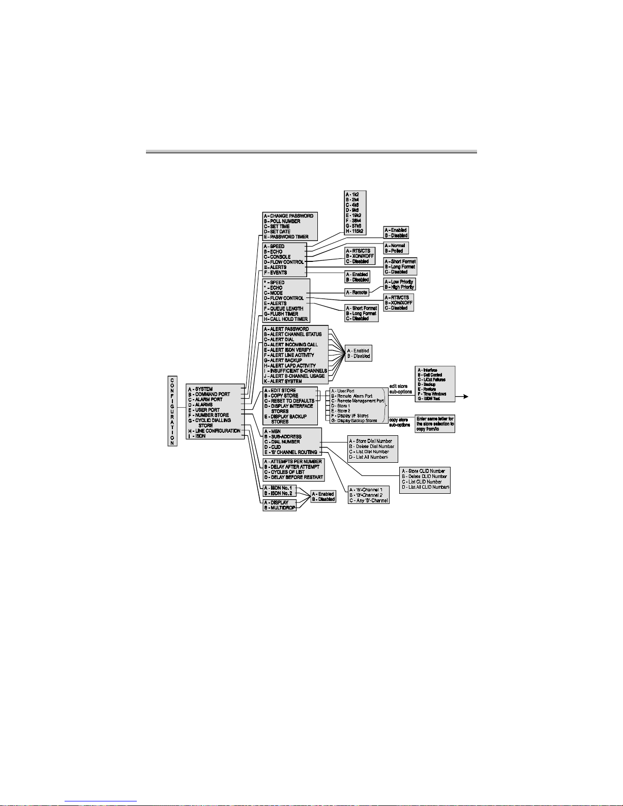
SBU128
User Manual
80-10200000-0111–2
11.1 Configuration Menu
Page 75
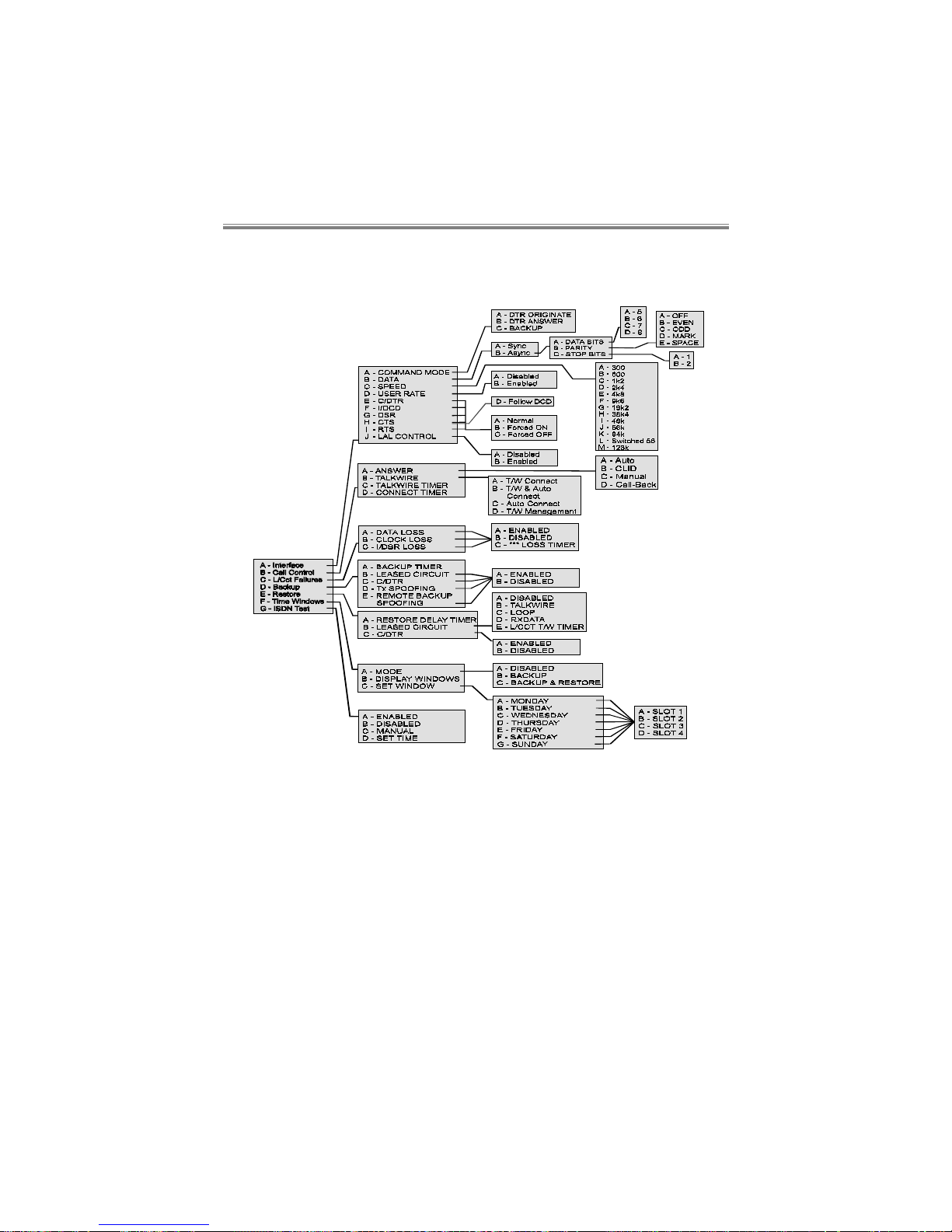
Command Maps
80-10200000-01 11–3
Page 76
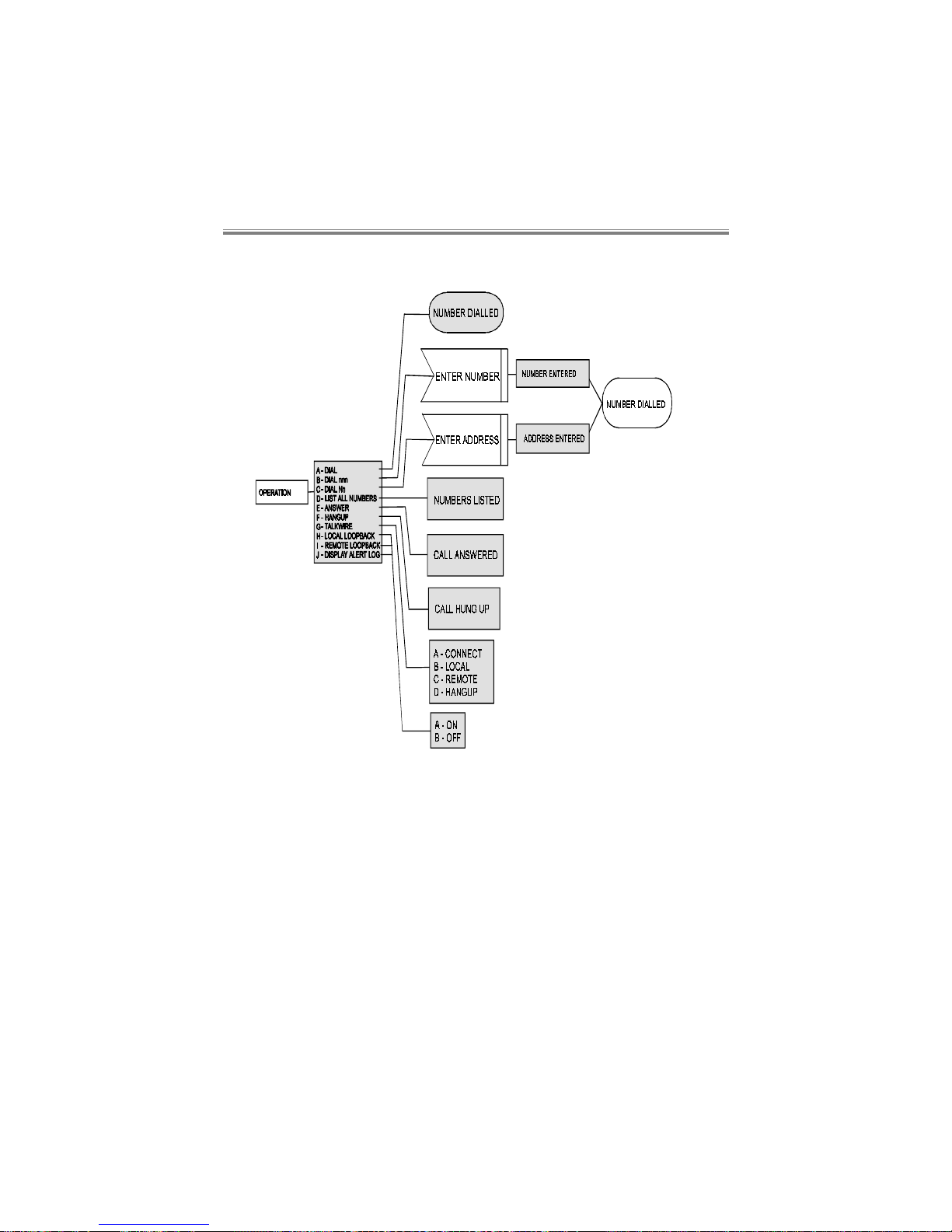
SBU128
User Manual
80-10200000-0111–4
11.2 Operation Menu
 Loading...