

Page 1

SmartSwitch™ Router 250
ADSL-DMT
Quick St art Guide
P/N 222-00526-01
Page 2

CONTENTS
INTRODUCTION.......................................................................................3
HARDWARE INSTALLATION .................................................................7
ACCESSING QUICK STAR T ....................................................................9
ROUTER CONFIGURATION ..................................................................14
APPENDIX A. INSTALLING AN ETHERNET ADAP TER AND
A TCP/IP PROTOCOL..............................................................................20
APPENDIX B. HARDWARE REFERENCE ...........................................23
APPENDIX C. FEDERAL
COMMUNICATIONS COMMISSION (FCC).........................................30
CONTACTING CABLETRON TECHNI CAL SUPPORT.......................32
1
Page 3

2
Page 4

INTRODUCTION
♦ The Sma rt Sw i tch ™ Router 250
The SmartSwitch™ Router 250 provides Internet an d Corporate
access for telecommuters, home and remote office workers, and
Int er net use rs at high-s pee d asymm etri ca l da ta rates of up to 640 Kb ps
upstream and 8.0 Mbps downstream .
The router takes full advantage of Asymmetric Digital Subscriber
Line (ADSL) technology and uses Asynchronous Transfer Mode
(ATM) to provide remote Ethernet LAN connectivity via a single
ADSL line. Bec ause AT M tec hnolog y s uppo rt s mult ipl e v irtu al circ ui t
connections, use rs connected t o an Ethernet LAN can access several
net w ork ser vices simu lta n eousl y.
♦ Cabletron Quick Start
The router features an easy-to-use W indows-based management
applicat ion. It also has several built-in features that let users connect
to a Network Service Provider (NSP) in minutes.
3
Page 5

♦ This Gu i de
This guide describes the configuration process involved in setting up
an ATM-based virtual circuit connection to a network service
provider. It shows you how to:
•
•
•
•
•
Connect the router’s cables
Confi gure your Windows 95 PC (or Windows 98 or
Windows NT 4.0)
Inst all the Cabletron DSL Tools
Configure t he router for yo ur Internet Ac count
Connect to your Network Service Provid er or Int ernet Service
Provi der
4
Page 6

♦ Before You Be g in.. .
System requirements fo r Ca bletro n Qu ic k Sta r t
•
•
•
•
•
Windows 95, 98, NT 4.0, or Windows for Workgroups 3.11
Ethernet ne tw ork interface card (NIC)
Microsoft TCP/IP sta ck installed and running on your PC
CD-ROM drive
Web Browser
Information to collect from your Network Service
Provider
Which link protoc ol should you use?
•
•
PPP
RFC 1483 (SNAP Encapsulation)
•
RFC 1483MER (M A C Encapsulated Routing)
5
Page 7

Which network options should you use?
♦
•
•
•
Bridging
IP Routing
Both Bridg ing and IP Rout ing
Contents of the Box
You should fi nd the f ollowing ite ms :
•
•
•
SmartSwitch™ Router CD and Quick Start guide
(thi s guide)
SmartSwitch™ Router 250
Cables:
One power ca ble
One Ethernet 10Base-T (crossover) cable
One ADSL/ISDN cable
6
Page 8

HARDWARE INSTALLATION
♦ Instructions to Install the SmartSwitch™ Router 250
Hardware:
1. Ensure that the Power Switch on the router is OFF. Connect the
router to the AC power source using the power cable.
2. Connect the rout er to the computer workstation’s Ethernet card
using the crossover cable lab eled "Ethern et 10Base-T ,
Crossover" (RJ-45 connect or). If you are connecting t o a hub,
use a standar d 10Base-T straight-thro ugh cable (not pr ovided).
3. Connect the ro uter to the ADSL line using the cable labeled
"ADSL or ISDN" (connect the RJ-45 connector to the router’s
ADSL R-DM T port and the other end of the cable to the
Telephone Jack).
4. Switch th e router Power Switc h ON
.
7
Page 9
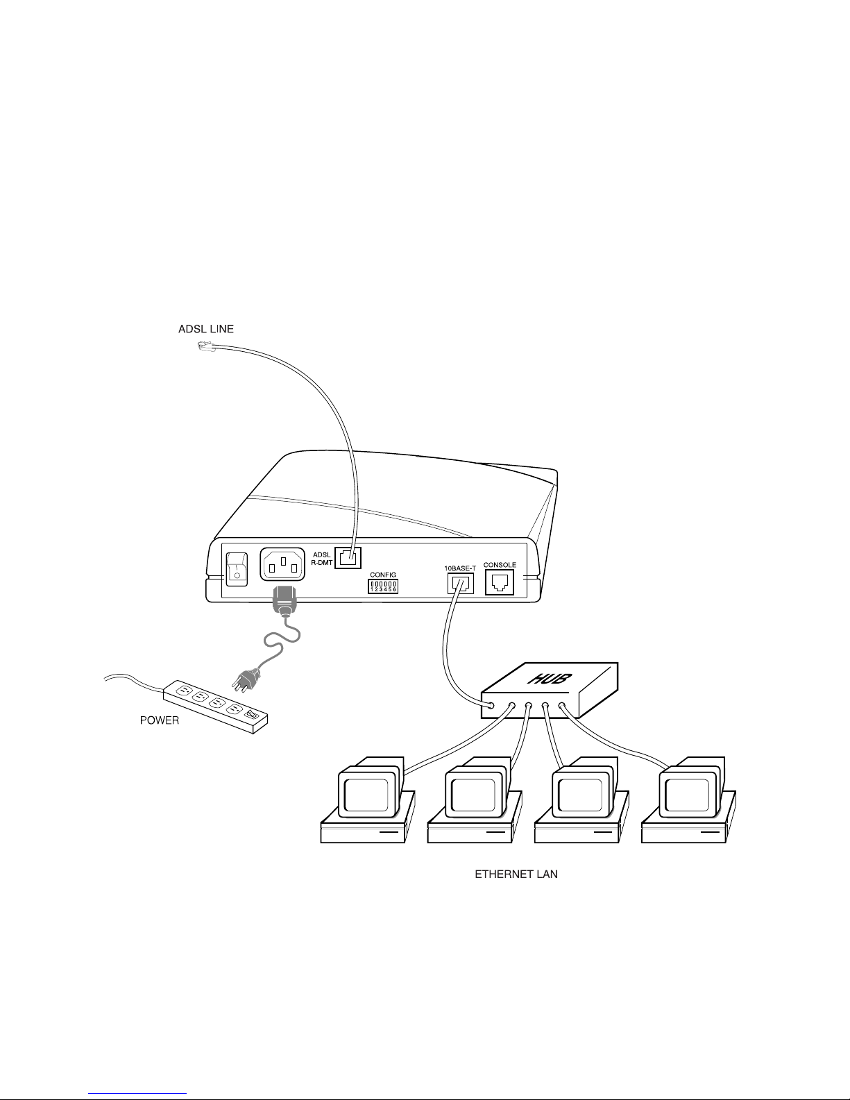
♦ SmartSwitch™ Router 250 Installation Diagram
The following diagram shows the back panel of the SmartSwitch™
Router 250 and the locati on of jac ks.
8
Page 10

ACCESSING QUICK START
To acces s Q uick Start, you will first configure your PC to obtain an IP
address aut omatically and then i nstall the Qui ck Start program . The
following ste p-by-step instructions will get you started quickly.
♦ Configure your Windows 95 PC for TCP/IP
This section assumes that you have already:
✔
connected the cables.
✔
pow e r e d the ro ut er on .
Note:
The following confi guration ins tructions also apply to
Windows 98 and NT 4.0.
9
Page 11
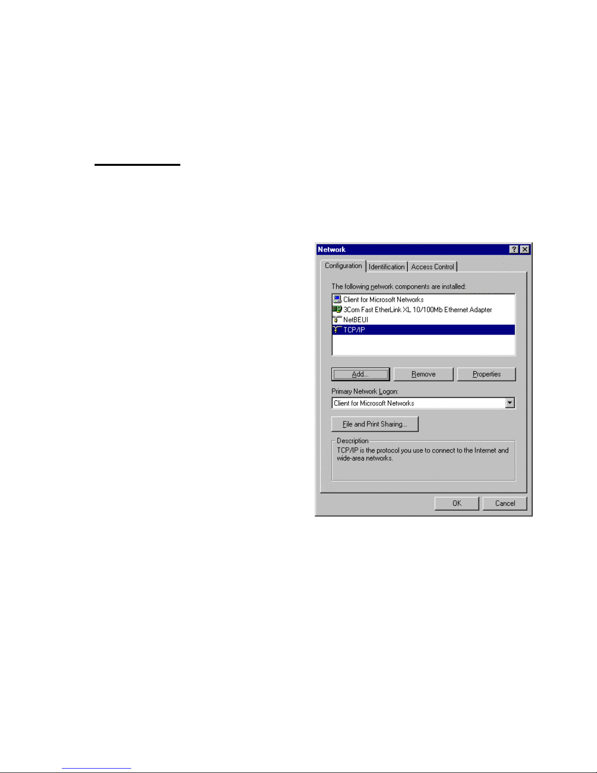
Instructions:
1. You should se e the
Network Neighborhood
desktop.
Note:
If you don’t see the
Network Neighborhood
icon on your desktop, you
need to in stall an Ethern et
adapter. Refer to
Appendix A
.
2. From the taskbar, click the
Star t
Sett ings,
➤
3. Y ou are now in the
button, select
➤
Control Panel,
Network
.
Network
window. In the
icon on your
Configuration
double-cl ick
configure your network
adapter).
4. In the
enable
TCP/IP Properties
Obta in an IP ad d res s a utom at ic a lly
button next to it.
10
tab pa ge,
TCP/IP
(to
window, in the
IP Address
tab page,
by clicking the
Page 12

5. Click
OK
.
♦
6. Answer
Yes
to "Do you want to restar t your computer?" Your
computer will reboot.
Note:
(
If your settings were already configured with these
att ributes, you will not be prompt ed to reboot and a reboot is not
necessary.)
Install Cabletron DSL Tools on your PC
This section assumes that you have already:
✔
connected the cables.
✔
pow e r e d the ro ut er on .
✔
set your PC to obtain an IP address automatically.
✔
rebooted your PC.
Instructions:
Insert the CD into your CD-ROM drive. If Auto-play is enabled, the
Cabletron Systems Installation CD
If you do not see the
Cablet ron Systems Ins tallation CD
window w ill be displayed.
window,
then follow these steps:
11
Page 13

Windows 95, Windows 98, Windows NT 4.0:
♦
1. From your PC’s desktop, double-click
My Computer
.
2. Double-click the Cabletron icon (your CD-ROM drive).
3. Double-click
index.htm
.
4. Follow the on-screen instructions .
Note:
The Cabletron DSL Tools are in stalled in the C:\ DSL
directory by defaul t. However, you may choose to install the Tools in
another dir ectory.
Access Quick Start
This section assumes that you have already:
✔
connected the cables.
✔
pow e r e d the ro ut er on .
✔
set your PC to obtain an IP address automatically.
✔
rebooted your PC.
✔
installed the Quick Start application software.
12
Page 14

Instructions:
1. From the taskbar, click the
Start
button (located on your PC
desktop).
2. Select
3. Select
DSL
Programs
Cab l etron D SL Tools
. A pop-up list of your programs will appear.
and then click
. Quick Start will automatically connec t to the router. If the
connection fail s, make sure that your cables are correctly
connected and that t he router is powe red on.
4. You will the n be asked to change the
your new password twice. (See ne xt page for inst ructions on
configuring your router.)
admin
Quick Start for
password. Enter
13
Page 15

ROUTER CONFIGURATION
After you have started the Quick Start applica tion and have ent ered your
password, you are ready to enter the following information in the Quick
Start configurator.
♦ Configuration Instructions
1. Network Options
Sel ec t either
IP Routing
2. Link Protocol
Sele ct one o f the foll owi ng th ree p rot oc ols ( che ck whi ch pro to col
is support ed by your Network Provider):
• PPP
If PPP is selected, you will need to enter a
Password
• RFC 1483
If you are using RFC 1483, do no t enter a
Password
, or
Bridging
for your Interne t connection.
for your Interne t connection.
, or both.
User Name
User Name
and
and
14
Page 16

If IP routing and NAT are enabled, you will be prompted to
enter a
Source WAN IP Address
inf ormati on from your ISP or your Network Administrator.
If NAT is OFF, you may still need to enter
Addr ess
information. Y ou will obtain this information from
your ISP or your Network Administrator.
• RFC 1483MER (MAC Encapsulated Routing)
If MER is selected, you will be prompted to ent er a
WAN IP Address
. You will obt ain this inf o rmation from
your ISP or your Network Administrator.
3. In ternet Ac co unt (PPP only )
Enter the follow ing information to config ure your rout er for
accessing the Internet:
•
User Name
. You will obtain this
Sour ce WAN IP
Sour ce
•
Password
4. DNS Information
Enter this info rm ation (ava ilable from your ISP) for accessi ng
the Internet.
15
Page 17

•
Domain Name
•
•
Serv er Address
Second Server
5. Options
The f oll owi ng opti on s ar e a lso av ail ab le for fu rt he r confi gu ra tion
of the router. Click Optio ns Menu to access them.
•
•
Select Router to Configure
This application will attempt to contact the default IP
address of t he router (192.168.254.25 4). You may also
reconnect to another router with a different IP address.
Change your LAN IP Settings
This field allows you to specify the LAN IP address of the
rout er t hat y ou are co nfi guri ng. This ad dre ss becom es a ct iv e
aft er you save your changes and reboot the router .
•
Change your WAN IP Settings
This allows you to specify the WAN port IP address of the
router that you are configuring and set Network Address
Translation (NAT). This address becomes active after you
save your changes and reboot the router.
16
Page 18

•
Ch oo s e a P V C
The Quick Start application defaults the VPI/ V CI numbers
to 0 and 38 respectively, unless they have been
preconfigured. Your Netw ork Service Pr ovider may have
decided on different values to use. If the value chosen by
your NSP is not the default value, then enter the VPI/VCI
that you have been give n.
•
6. Tools
The followi n g tools a re available to perfo rm advanced c onfigurations, fi le system manageme nt, software maintenance, and data
traffic monitoring.
•
SNMP Options
The Comm unity Name and UDP Port Num ber may be
changed for security reasons or to all ow SN M P mo nitoring
of a device located on the LA N w hile running NAT.
Consult with your Network Administrator to determine if
you need to change th e default settings.
Terminal Window
The Termi n al Window lets you acces s the Command Line
Int erface dire ctly from Quick St art with a cust om ized
terminal emulator.
17
Page 19

•
Execute Scri pt
The ro ut er copi es comman d fi l es cre at ed on the PC and th en
executes them on its first startup.
•
•
•
Backup/Upgrade
Upgrade / Backup allows you to backup the rout er’s
configuration files as well as easily upgrad e the router’ s
software (using a buil t-in TFTP utility).
Reboot from Network
This tool allo w s you to try a new version of s oftware before
committing to it by loading this new software from your PC
without writing it to the router’s file system. This tool is
als o used to update th e router’s bootstrap modul e.
Port Monitor
Port Monitor prov ides graphic feedback on the operating
sta tus and bandwidt h utilization of your rout er.
7. Exit Qui ck Start
Click
entered and rebo ots the router .
. This sav e s the configur ation infor m ation you just
Exit
18
Page 20

8. Restart your PC
After the router has successfully rebooted, you must restart your
PC if you have entered DNS information (see Step 4): the PC
will acquire t he DNS (Domain Name Server) information from
the r outer .
If you need additional help or information:
Use the Help File (H elp button on the screen or pre ss the F1 key
on your PC keyboard).
19
Page 21

APPENDIX A. INSTALLING AN
ETHERNET ADAPTER AND A TCP/IP
PROTOCOL
In most cas es, Plug and Play wi ll automatically detect your network
adapter and install any necessary dr ivers. However, if Plug and Pl ay fails,
the instr u ctions below will assist you in instal lation and set u p for the
adapter and prot ocol setti ngs in Windows 95.
♦ Windows 95 - Instructions to configure an Ethernet
adapter and protocols:
This secti on assumes that Windows 95 has already been successful ly
installed on your computer. For additional information about
20
completing any options in the Adap ters and Proto cols dialog
windows, use the Hel p button. Please ref er to your Microsoft
Windows 95 Installation Guide for additional information.
Page 22

Adapter Setup
1. From the taskbar, click the
corner o f your PC screen).
2. Po int to
Network
3. In the
Network
Settings
icon.
window, from the
, click
Control Panel
Add.
4. In the
Adapter
5. In the
Select N etwork Component Type
, and then click
Add
Select Network Adapters
adapter (manufacturer and adapter model) that matches your
har dw a re. Click
instructions. Click
Have Disk
OK
.
Protocol Setup
Start
button (located at the l ow er left
, and double-cl ick the
Configuration
tab page, click
window, click
.
window, select the network
and follow th e in st allati o n
1. From the taskbar, click the
corner o f your PC screen).
2. Po int to
Network
3. In the
Add
Settings
icon.
Network
.
, click
Start
Control Panel
button (located at the l ow er left
window, from the
, and double-cl ick the
Configuration
tab page, click
21
Page 23

4. From
Selec t Network Component
, click
Protocol
, and then
click
5. In the
Manufacturer
6. On the right hand side of the
select
OK
Add
.
Select Network Protocol
window, select
Microsoft
.
TCP/IP
as the
Select Network Protocol
Network Protocol
. Clic k
OK
window,
(and click
in the Network dialog window). Reboot your PC so tha t the
new settings will take effect.
You can now proceed with installing the software on your PC,
beginn ing on page 11.
as the
22
Page 24

APPENDIX B. HARDWARE REFERENCE
♦ SmartSwitch™ Router 250 Hardware Specificat ions
LAN Interfaces
WAN Interfaces
ADSL Modem
Specifications
ADSL Modulation
Technique
Analog Telephone
Line Support
Processor
One Et her net port, 10Base-T
(twisted pair RJ45)
LAN speed of 10 Mbps
One ADS L WAN interf ace (RJ45)
Up to 8 Mbps down s tr eam
Up to 640 Kb ps upstream
Discrete Multitone (DMT)
Co-operates with external splitter
Motorola® MPC860 operating at
25 MHz
Physic al
Specifications
1 MB Fla sh Memo ry , 2 MB DR A M
Dim e n s i o ns : 8. 4 W x 7.0 D x 1.7 H inc hes
21.3 W x 17.8 D x 4.3 H cm
Weight: 1.5 lbs. (. 68 Kg.)
23
Page 25

Operating
Environment
Temperatur e: 40°F to 105°F ( 5°C to 40°C)
Humidity: 20% -80%, non-condensing
Power
Requir ements
Agency Approvals
AC Voltage: 100 to 12 0 VAC, 220 to
240 VAC
Frequency: 50/60 H z
Power Consumpt ion: 15 W max imum
Buil t- in power supp ly
Safe ty: UL 1950, CSA 22.2, EN60950
Emissions: FCC Part 15 C lass B, EN55022/
CISPR22 Class B
Immunity: EN 50082-1
Certifications: Per relevant ADSL standards
24
Page 26

♦ Front Panel
The front panel displays the activi ty of the SmartSwitch™
Router 250.
LED States
INDICATOR DESCRIPTION
PWR
TEST
LINK
WAN
LANT
LANR
Green: Power is appl ied
Off: Power is not applied
Ambe r: Running router Powe r-On-Self Test (POST )
Green: Router POST test was successful
Of f: Router is non operational
Amber: Establishing ADSL modem link
Green: ADSL modem link suc ceeded
Off: ADSL lin k is no n oper atio nal
Green flashing: Transmit or receive on WAN only
Off: No WAN traffic
Green flashing: LAN transmit traffic indication
Off: No LAN transmit traffic
Green flashing: LAN receive traffic indication
Off: No LAN receive traffic
25
Page 27
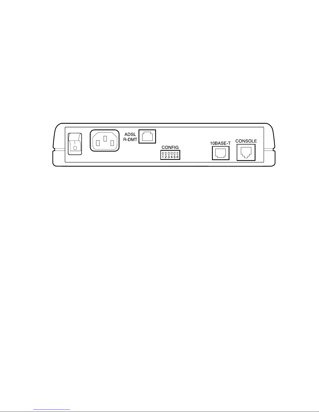
♦ Rear Panel
The rear panel contains all Ethernet, DSL, cons ole, and power
interfaces.
10BASE-T
The 10Base-T Ethernet LAN interface. The router is connecte d to the
Ethernet LAN with a twisted pair Ethernet cable at this interface.
CONSOLE
RS232 i nter fa ce u sed as a c ont ro l cons ol e co nnect ion th rou gh an RJ 45
connector. It supports a set of RS232 signals for connectio n to an
26
asynchronous port on a terminal, PC, o r other compute r in ter m inal
emulation mode.
CONFIG
Configurat ion switches wh ich control s oftware execut ion.
POWER
A standard AC power connector and O N /OF F switch labeled l/0.
Page 28

ADSL-DMT
Connection to the external telephone line interface.
♦
Connections
Ethernet LAN Connection
The uni t provides 10 Mbps Etherne t/IE EE 802.3 support. The
Ethe rnet LAN connection is th rough an 8-pin RJ45 10Base-T jack on
the r ear of the unit.
ADSL-DMT WAN Connection
The router provides one ADSL port. ADSL provides hig h-speed data
rat es. ADSL connectivity is through an 8-pin RJ45 jack on the rear of
the unit.
Console Connection
The console por t prov ides asynchronous RS232 communications
connectivity to a terminal, comput er, or modem. The console
connection is thr ough an 8-pin RJ45 jack at the rea r of the unit. The
console port is optionally used for configuration and management of
the r outer .
27
Page 29
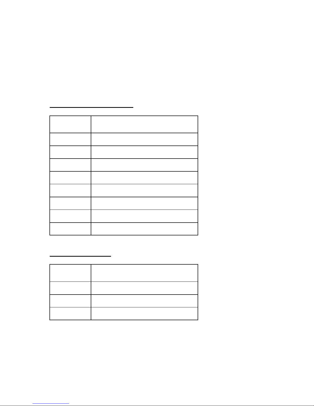
♦ Port Descriptions
Ethernet 10Base-T Port
Pin Signal Name
1 Twisted pair transmit +
2 Twisted pair transmit 3 Twisted pair receive +
4 Ground
5 Ground
6 Twisted pair receive 7 Ground
8 Ground
ADSL-DMT Port
Pin Signal Name
1 Not connected
2 Not connected or line B
3Line A
28
Page 30
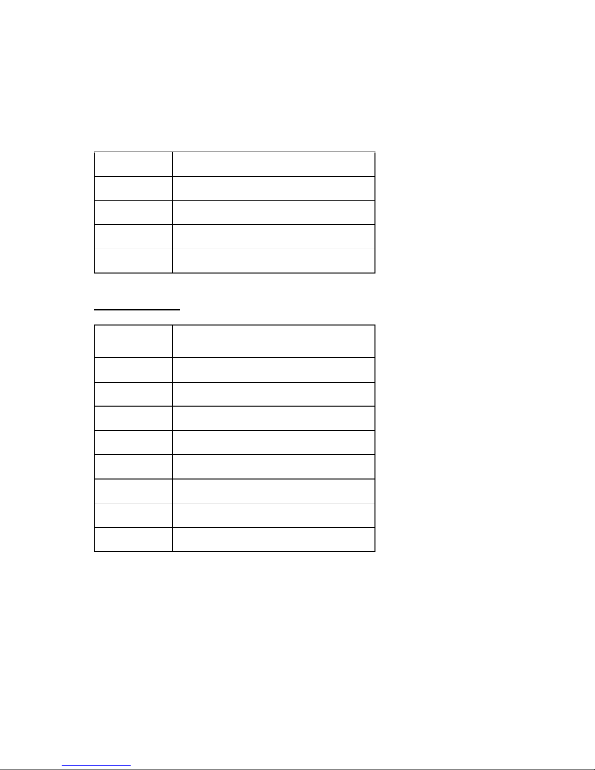
4 Tip or Line A
5 Ring or Line B
6 Not connected or Line B
7 Not connected
8 Not connected
Console Port
Pin Signal Name
1 Receive data
2 Request to send
3 Not used
4 Transmit data
5 Ground
6 Clear to send
7 Not used
8 Ring indica tor
29
Page 31
APPENDIX C. FEDERAL
COMMUNICATIONS COMMISSION (FCC)
Part 15 CLA S S B Statement
Section 15.105(b) of the Code of Federal R egulations
Note:
This equipment has been tested and found to comply with the limits
for a C la ss B digita l device, pu rsuan t of Part 15 of the FC C Ru l es. The se
limits are des igned to provide reasonable protection against har m ful interference in a res idential in stallati on. This equipment generates, uses, and
can radiat e radio freque ncy energy and, if not installed and use d in accordance with the instructions, may cause harmful interfere nce to radio communications. Ho w ever, t here is no guarante e that interf erence will not
occur in a particular installation. If this equipment does cause harmful
interfe rence to radio or television re ception, which can be determined by
turning the equipment off and o n, the user is en couraged to tr y to correct
the i nterferen ce by one or more of the f ollowing measures:
• Reorient or relocate the receiving antenna.
• Increase the separation between the equipment and receiver.
• Connect the equipment into an outlet on a cir cuit di fferent from that to which
the receiver is connected.
• Consult the dealer or an experienced radio/TV technician for help.
30
Page 32

CAUTION: Any changes or modifications not expressly approved by the party
responsible for thi s device could void the user’s authority to operate this equipment.
Canadian D.O.C. Noti ce
This product conforms with Canadian Class B emissions regulations.
Ce pr oduit se conforme aux réglements d’émission canadienne classe B.
Instructions for Trained Service Personn el Only
CAUTION: Danger of explosion if batt ery is incorrectly
placed. Replace only with the same or equivalent type
recommended by the manufacture r. Dispose of used
batteries according to the manufacturer’s instructions.
Approvals
Safe ty: EN60950, UL 1950, CUL to CSA 22.2 No. 950
Emissions : FCC Part 15 Class B, EN55022/ CISPR2 2 Class B
Immunit y: EN50082-1
Certifications: Per relevant ADSL standards
31
Page 33
CONTACTING CABLETRON
TECHNICAL SUPPORT
Before you cont ac t Tech ni cal Sup po r t, plea s e hav e the
following information ready:
•
•
•
•
•
Router model number
Router software versi on
Date of purchase
Type of Operating System (Windows 95, W indows 98,
Windows for Workgroups, or W indows NT 4.0)
Description of the problem
32
Page 34
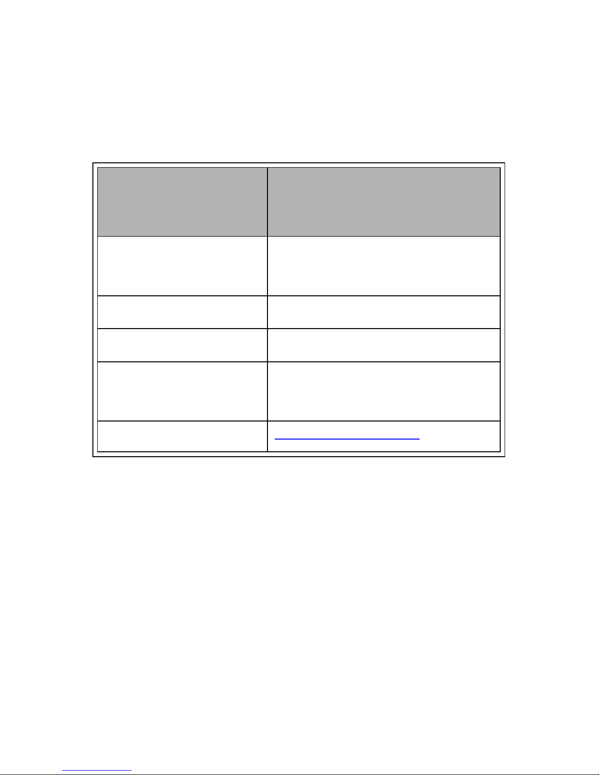
Ho w to con tact
Technical Support in
the U.S.
Addresses / Numbers
Telephone
E-Mail
Fax
Address
Web S ite
1-603-332-9400
Monday-Friday; 8 A.M. - 8 P.M.
Eastern Time
1-603-337-2211
Cabletron Systems
35 Industria l Wa y
Rochester, NH 03867
http:// ww w.cabletron .co m
33
 Loading...